inboard engine installation – template for engine bedsbateau2.com/free/inboard_tpl_notes.pdf ·...
TRANSCRIPT

Inboard engine installation – Template for engine beds
(This tutorial is excerpted from our shop manual “Plywood Cored Composite Boat Construction”. The manual covers the other parts of the inboard engine installation including the drive train, shaft, cutlass bearings, shaft seals, struts and much more.)
Inboard engines are mounted on engine beds aligned with the shaft.The engine beds can be solid wood girders, laminated wood or metal brackets bolted to stringers.This tutorial describes an easy and accurate method to build those engine beds.
To obtain the dimensions for the engine beds, we could hang the whole engine somewhere in the boat, move it around until if fits and line up then take dimensions for the engine beds.With a 1,000 lbs or heavier engine, this procedure is not practical.
A better method is to make a light plywood mock up of the engine, line up that "engine template” with the shaft and measure everything from there.
That template is easy build and much more practical.
Outline:
This is a typical plywood engine template:
The flat piece of plywood represents the engine with transmission in plan view (from above).

In the rear, the template is fitted with a round circle of plywood representing the shaft coupling, transmission side.On the front of the template, there is a small piece of wood similar to a gun sight. The line going from the sight to the middle of the coupling is the boat's shaft axis.We will pull a steel line (fishing line) from the front sight, through a hole in the middle of the coupling, all the way through the stern tube to align all drive train components, engine included.On each side of the plywood template, small blocks of wood represent the engine rubber mounts.For a small engine (less than 100 HP) we make the engine mounts 3.5" long, 2" wide and 1.5" high. That is the section of 2x4. Cut 4 slices 2" wide and you have your mounts.
Coupling and mounts must be accurately fastened to the plywood template: coupling exactly on the centerline and mounts at the correct width, length and height.
With the template lined up along the boat's shaft axis, we can take measurements to build the engine bed.
Later, we may use the template to align the other parts of the drive train: stern tube, strut, cutlass bearing and packing gland or shaft seal.
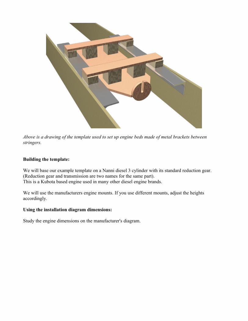
Above is a drawing of the template used to set up engine beds made of metal brackets between stringers.
Building the template:
We will base our example template on a Nanni diesel 3 cylinder with its standard reduction gear.(Reduction gear and transmission are two names for the same part).This is a Kubota based engine used in many other diesel engine brands.
We will use the manufacturers engine mounts. If you use different mounts, adjust the heights accordingly.
Using the installation diagram dimensions:
Study the engine dimensions on the manufacturer's diagram.

Note that the engine block shaft axis (crankshaft) and transmission shaft are different.Many engine dimensions are given relative to the crankshaft but our stern tube, prop shaft and engine beds must be lined up with the transmission axis. Because of the reduction gear, that axis is often offset a little below the engine block axis.
In this case, the output shaft (transmission shaft, prop shaft axis) is 2.66" below the crankshaft.( We will use engineering units in decimal inches, we show a conversion table further down).Unless the engine is fitted with a down angle transmission, the two axis are parallel.
The engine mount bases are 1.89" below the engine block axis.That means that the engine mounts will be a little above the output shaft axis: 2.66 - 1.89 = 0.77" above.
For the width, the engine mounts centers are 7.48" away from the center line.
Lengthwise, the rear mounts center is 7.07" in front of the coupling face.That gives us the 3 dimensions based on the shaft axis:0.77 above, 7.48 from center and 7.07 forward of the coupling.
The front mounts are at the same height and width than the rear ones(this is not always the case) but 12.68" forward.That means they are 12.68 + 7.07 = 19.75" forward of the coupling.
Now that all the dimensions are clear, let's build the template.
Assembling the template:
The main component is a piece of plywood that represents the engine.
Cut it roughly to the dimensions of the engine: about 27” long and 10” wide, tapered at one end to

represent the transmission. The exact shape does not matter. Draw a center line.
Fabricate the fake engine coupling.Almost all small engine couplings are 4" in diameter: cut a 4" circle out of 1/2" plywood.Drill the center to 1/2" diameter, the steel line used for alignment will go through that hole.If you do not want to thread the line through that hole, cut a slot in the flange.
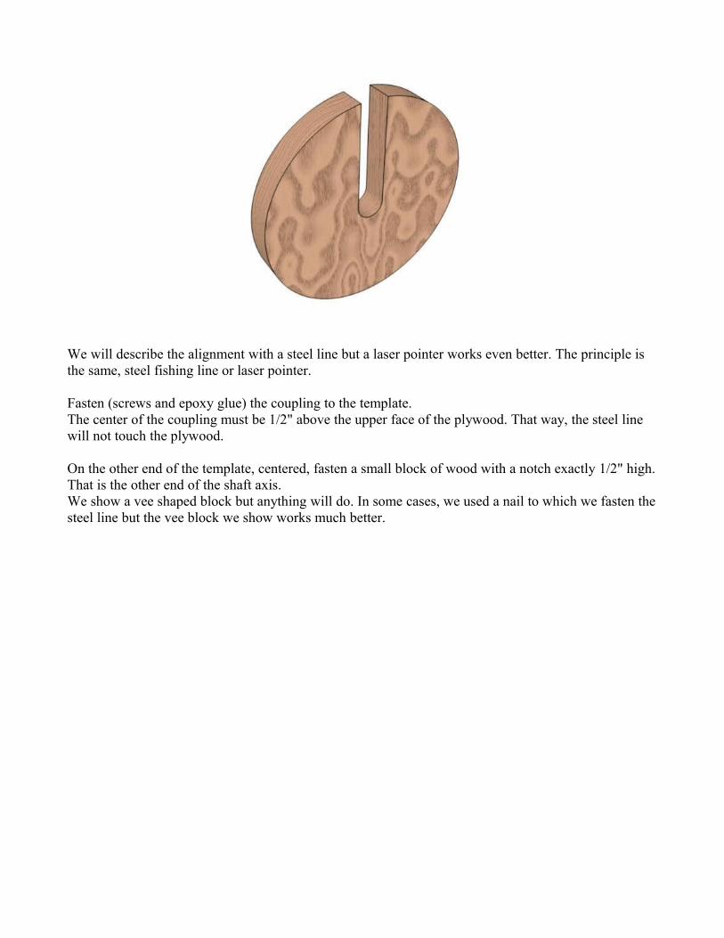
We will describe the alignment with a steel line but a laser pointer works even better. The principle is the same, steel fishing line or laser pointer.
Fasten (screws and epoxy glue) the coupling to the template.The center of the coupling must be 1/2" above the upper face of the plywood. That way, the steel line will not touch the plywood.
On the other end of the template, centered, fasten a small block of wood with a notch exactly 1/2" high.That is the other end of the shaft axis.We show a vee shaped block but anything will do. In some cases, we used a nail to which we fasten the steel line but the vee block we show works much better.
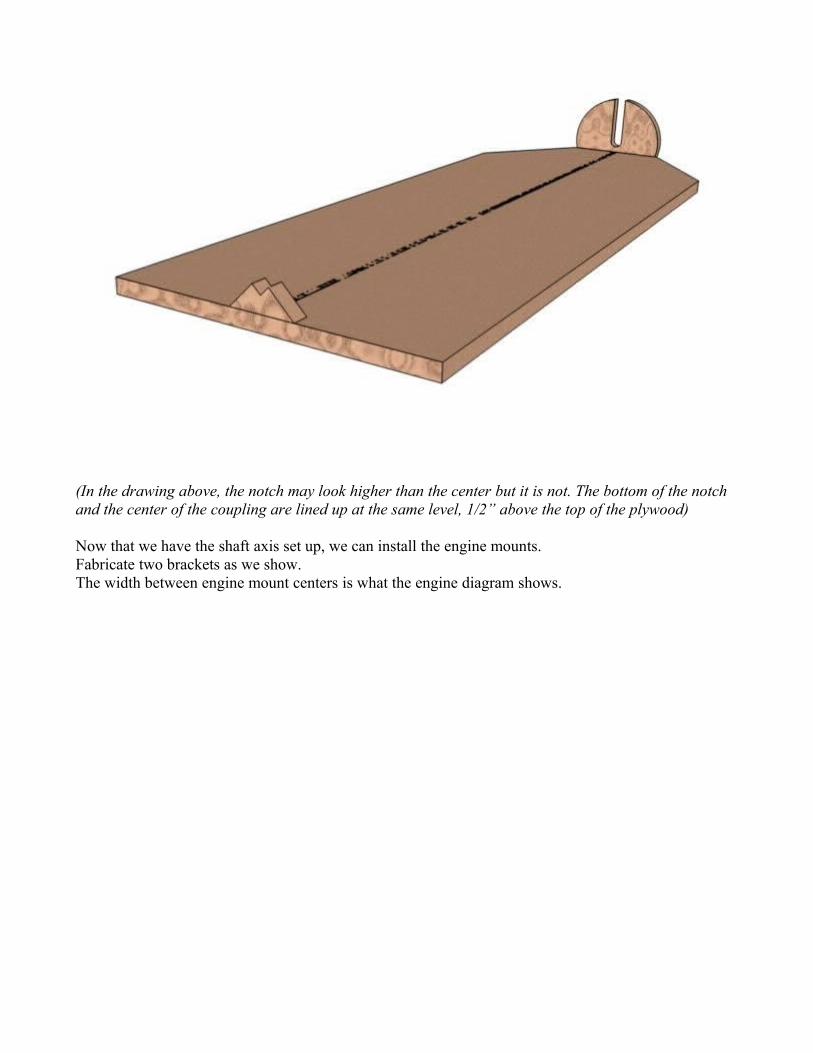
(In the drawing above, the notch may look higher than the center but it is not. The bottom of the notch and the center of the coupling are lined up at the same level, 1/2” above the top of the plywood)
Now that we have the shaft axis set up, we can install the engine mounts.Fabricate two brackets as we show.The width between engine mount centers is what the engine diagram shows.

On the template, draw two lines across the center line to represent the transverse axis of the 2 engine mount pairs.One at 7.07” from the rear face of the coupling for the rear mounts and one at 19.75”.Center your two pairs of engine mount brackets on those lines.Raise the mounts to the correct level with spacers.

The engine mounts height above the shaft axis is what we calculated earlier: the lower face of the mounts is 0.77” above the shaft axis.Keep in mind this is above the shaft axis, not the plywood face. Since the plywood face is 1/2” below that axis, we must add 1/2” to our previous calculations.
Fasten the whole thing together.
How to use the template.
In our example, the hull in which we will install the engine beds is at the building stage of inside fiberglassed with stringers installed.
Start by installing the shaft axis steel line in the boat.

In our plans, we show reference points. Usually we show a point where the shaft axis traverse a mold or a frame forward of the engine and another on the stern post.Sometimes the rear point is below the transom, in that case, clamp a batten to the transom and measure.Look at your plans, it should be clear.
Drill a hole through those points and install a very tight thin steel line.A good way of keeping the line tight is to fasten it to the mold or frame forward, run it through the stern post hole and attach a heavy weight on it behind the stern post.The weight will keep it tight while you move the template around.
With the shaft axis in place, put your template about where the engine will be installed.Align the template with the shaft axis line.The line must pass through the front slot and in the middle of the coupling.The opening in the center of the coupling is drilled oversize for a good reason, it is much easier to align the template when the steel line does not push against the edges.
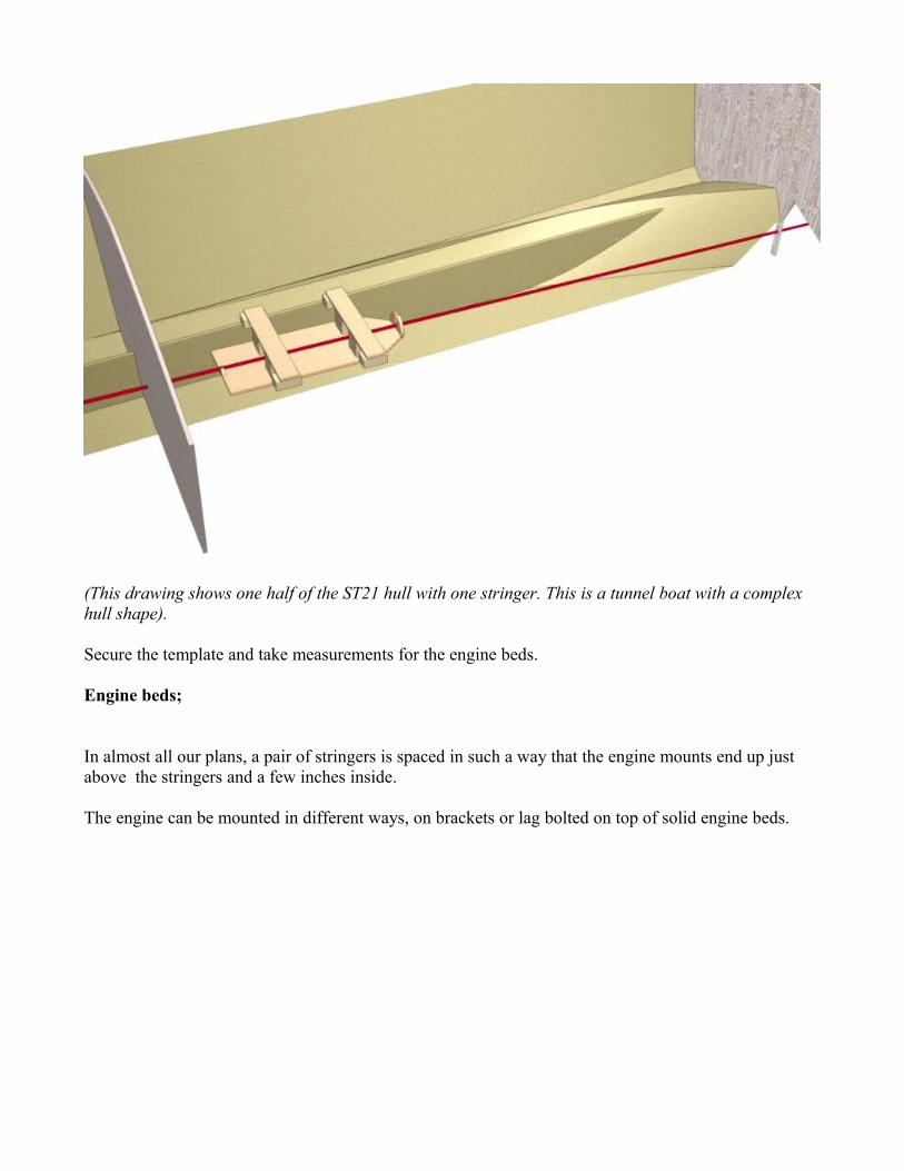
(This drawing shows one half of the ST21 hull with one stringer. This is a tunnel boat with a complex hull shape).
Secure the template and take measurements for the engine beds.
Engine beds;
In almost all our plans, a pair of stringers is spaced in such a way that the engine mounts end up just above the stringers and a few inches inside.
The engine can be mounted in different ways, on brackets or lag bolted on top of solid engine beds.

All our plans show the preferred arrangement and the width of our stringers takes in account the type of mounts or brackets.
The most common method is to bolt the engine mounts to metal brackets, steel or Al. Those brackets are through bolted to the stringers.The brackets can be full length or in two pieces: a separate one for the forward and rear mounts.
In most of our designs, the spacing of the stringers is calculated to receive the brackets on their inside face. The stringers are then reinforced by extra layers of wood on their outside face, the total thickness and length is shown on the plans. Those extra layers of wood extend all the way to the bottom of the hull and are fiberglassed the same way than the stringers. They become an integral part of the framing.

The drawing does not show the extra layers of wood used to reinforce the stringers but this is specified on your plans.
In some cases, for example if the builder installs an engine with narrower engine mounts, the stringers will be reinforced on their inside face. This becomes very clear when using the template.. The other engine mounting method uses mounts lag bolted on top of wider stringers/engine beds.
In our example, we use the hull of the ST21. The engine can be installed on brackets or on top of widened stringers.
Here is how to build the wide stringers/engine beds.
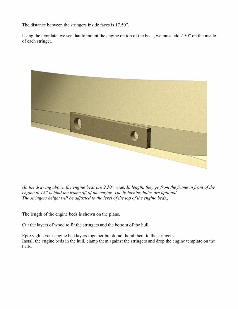
The distance between the stringers inside faces is 17.50”.
Using the template, we see that to mount the engine on top of the beds, we must add 2.50” on the inside of each stringer.
(In the drawing above, the engine beds are 2.50” wide. In length, they go from the frame in front of the engine to 12” behind the frame aft of the engine. The lightening holes are optional.The stringers height will be adjusted to the level of the top of the engine beds.)
The length of the engine beds is shown on the plans.
Cut the layers of wood to fit the stringers and the bottom of the hull.
Epoxy glue your engine bed layers together but do not bond them to the stringers.Install the engine beds in the hull, clamp them against the stringers and drop the engine template on the beds.

Do a final height adjustment and mark the outline of the beds on the stringers.Remove the template and epoxy weld the engine beds to the stringers then fiberglass.This done the same way than any other part of the framing: epoxy glued with fillets and taped seams.
With either method, you can later use the template and shaft axis to install the stern tube.
Laser:
The alignment can also be done with a laser beam.A laser pointer or a gun sight can be used, they cost very little.Using clamps, secure the laser beam in such a way that the beam passes through the alignment holes marked on the plans.In some case, this is easier with the laser behind the stern (when the hull is upside down) or with the laser inside in front of the last mold marked with a center (with hull right side up).
About dimensions:Metric is the easiest way to go. Get a metric ruler.If you want to use inches, you may have a problem with engineering dimensions. Few rulers are graduated in decimal inches.In that case, you must translate.Either make a table with all dimensions before hand or use the rules below.0.125" = 1/8.Half of that, 0.625" = 1/16.1/8 accuracy is sufficient for our template therefore, round up as follows:
.125 = 1/8
.250 = 1/4
.375 = 3/8
.500 = 1/2
.625 = 5/8
.750 = 3/4
.875 = 7/8
Metric is much easier.