inclined drift method for dispersed rock handling of...
TRANSCRIPT

SUST Studies, Vol. 12, No. 1, 2010; P:79-84
Inclined Drift Method for Dispersed Rock Handling of
Madhapara Hard Rock Mine, Bangladesh
A.K.M. Badrul Alam1, M Farhad Howladar
2, Choudhury Quamruzzaman
3 and Farid Ahmed
3
1 Department of Mining, Institute of Mining, Mineralogy and Metallurgy (IMMM), BCSIR, Joypurhat 2Dept. of Petroleum and Georesources Engineering, Shahjalal University of Science and Technology,
Sylhet 3114, Bangladesh. 3 Department of Geology and Mining, University of Rajshahi, Bangladesh.
Email: [email protected]
Abstract
Madhayapara Hard Rock Mine has the annual production target of 1.6 million ton. During the
loading and unloading of hard rock to bring it to the surface, certain amount of rock would be
dispersed and the dispersed rock should be handled for the economical as well as technical
point of view. The inclined drifting ranges between -270m and -334.8m, because -270m is the
production level and the arresting bean is situated in -334.8m level. The required width-height
ration for the inclined drift is 1.18. Considering the ratio, the stability of the inclined drift
method with respect to allowable compressive and tensile stress was examined and found that
the inclined drift would be stable within the stress field. It is found that the width and height
of the drift, height of the arch, side radius of the arch, center radius of the arch, vertical sided
portion of the drift and the finished area of the arch would be 3.5m, 2.96m, 1.16m, 0.96m,
2.42m, 1.18m and 9.48m2 respectively.
1. Introduction
Bangladesh lies between 22°34″and 26°38″N latitudes and 88°01″ and 92°41″E longitudes and as a
consequence falls in the northeastern part of south Asia. The location map of the study area is given in figure
1.1. Every mine has the loading and unloading facilities. The loading and unloading is done with in the skip
shaft shown in figure 1.2. A skip bucket is generally used to bring the rocks to the surface by loading and
unloading the bucket. After loading the skip bucket through the loading arrangement the rocks bring to the
surface through the skip bucket to the surface. During the loading and unloading process certain amount of rock
would be dispersed. The dispersed rock should be handled, in economical as well as technical point of view.
Thus the purpose of the research is to apply the inclined drift method to handle the dispersed rock properly in
the mining industry, Maddhapara Hard Rock Mine, Bangladesh.
80 A.K.M. Badrul Alam1, M Farhad Howladar2, Choudhury Quamruzzaman3 and Farid Ahmed3
Figure 1.1 Location map of the study area (Modified after Rahman, 1987).
Figure 1.2 Longitudinal section of skip shaft (KSSCC, 1996)
2. Width-Height Ration of the Inclined Drift
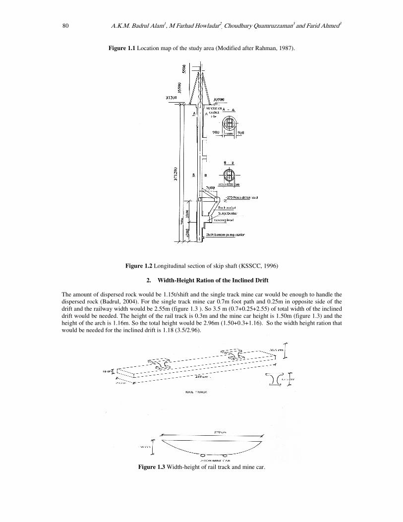
The amount of dispersed rock would be 1.15t/shift and the single track mine car would be enough to handle the
dispersed rock (Badrul, 2004). For the single track mine car 0.7m foot path and 0.25m in opposite side of the
drift and the railway width would be 2.55m (figure 1.3 ). So 3.5 m (0.7+0.25+2.55) of total width of the inclined
drift would be needed. The height of the rail track is 0.3m and the mine car height is 1.50m (figure 1.3) and the
height of the arch is 1.16m. So the total height would be 2.96m (1.50+0.3+1.16). So the width height ration that
would be needed for the inclined drift is 1.18 (3.5/2.96).
Figure 1.3 Width-height of rail track and mine car.

Inclined Drift for Dispersed Rock Handling for Maddhapara Hard Rock Mine, Bangladesh 81
3. Stability of the Inclined drift against stress field
The required width-height ration of the inclined drift is 1.18. The effect of compressive and tensile stress on the
roof and sidewall of the drift was examined considering different width height ratio. In this purpose the
following equations of Brady and Brown, 1985 were used. The equations are as follows-
δB = Tensile stress = Roof wall pressure = P(K-1+2K/q)……………………......……..(1)
δA = Compressive stress = Side wall pressure = P(1-K+2q) …………………………..(2)
P = vertical stress, K = ratio of horizontal – vertical pressure, q = ratio of width - height
3.1. Total vertical pressure The vertical pressure in the production level and in the level of arresting bean i.e., 334.8m was determined by
using the following equation-
P = Z × γ ……………………………………….......................................................… (3)
Z = Depth from surface, γ = Unit weight
i) The void ratio of the subsurface rock was determined by using the following equation-
ρd = GS × ρw / (1+e) ……………………..............................................................…… (4)
ρd = dry density, GS = specific gravity, e= void ratio, ρw = density of water
ii) The unit weight was determined by using the following equation-
γ = GS (1+W) × γw / (1+e) ………..................................................…………….…….(5)
ρd = dry density, GS = specific gravity, e= void ratio, ρw = density of water
After determination of the void ration and using the value in equation 5 the unit weight of the subsurface rock
was determined. After having the unit weight value the vertical pressure was calculated by using the equation 3.
The data of specific gravity, moister content and dry density are from KSSCC, 2001 for the subsurface
sedimentary rock which is up to 145.69m after this depth the hard rock started at the skip shaft position. So,
vertical pressure up to 145.69 was determined by using the equations 3, 4 and 5. The production level is in -
270m therefore the thickness of hard rock is 124.31m (270-145.69). Similarly the arresting bean is in 334.8m so
the hard rock thickness in -334.80m level is 189.11m (334.80-145.69). The unit weight of the hard rock is 21.26,
Kn/m3 (KSSCC, 1996). Thus the vertical pressure of the hard rock at -270m level is 2642.83 KPa and for -
334.80m level is 4020.47 KPa. The vertical pressure calculation results are shown in Table 1. For understanding
the Table-1, please check the appendix-1. The total vertical pressure for -270m level is 5696.71 KPa
(3053.88+2642.83) and for -334.80 m level is 7074.35 Kpa (3053.88+4020.83).
3.2. Compressive and Tensile stress
After putting the vertical pressure and the horizontal-vertical pressure ration (0.37, KSSCC, 1996) in the
equations 1and 2 the following equations for -270m and for -334.8m level were derived.
270m level Vertical pressure is 5696.71Kpa
δA = Compressive stress = P(1-K+2q)
= 5696.71 (1-0.37+2q) = 5696.71(0.63+2q) …………….(6)
δB = Tensile stress = P(K-1+2K/q)
=5696.71(0.37-1+2×0.37/q) = 5696.71(-0.63+.74/q) ………...(7)
334.80m level
Vertical pressure is 7074.35Kpa
δA = Compressive stress = P(1-K+2q)
= 7074.35 (1-0.37+2q) = 7074.35(0.63+2q) …………….(8)
δB = Tensile stress = P(K-1+2K/q)
= 7074.35(0.37-1+2×0.37/q) = 7074.35(-0.63+.74/q) ………...(9)
Using the equations (6), (7), (8) and (9) and taking different values for q corresponding Compressive and
Tensile Stress were determined. By using these data a graph has been prepare which is shown in figure 1.4.
3.3. Compressive and Tensile Strength
According to the the test result of core samples of KSSCC, 2001 report on geologic survey of borehole the
compressive strength is 92225.7 Kpa and the tensile strength is 9750 Kpa. Design compressive and tensile
strength is 73780.56 Kpa and 7800 Kpa respectively (KSSCC, 2001). The allowable compressive and tensile
stress is 24593.52 Kpa and 2600 Kpa respectively. The calculation is shown as follows-
σ allowable = σ design / FS = 73780.56 / 3 = 24593.52 Kpa
τ allowable = τ design / FS = 7800 / 3 = 2600 Kpa

82 A.K.M. Badrul Alam1, M Farhad Howladar2, Choudhury Quamruzzaman3 and Farid Ahmed3
3.4. Results and discussions By using the different values of compressive and tensile stresses with varying q value using the equations
6,7,8,9 and considering the allowable compressive and tensile stress the following figure has been prepared.
Figure 1.4 Width-height ratio and corresponding compressive and tensile stress.
From the figure 1.4 it is found that the required width height ratio is 1.18 which is within the allowable
compressive and tensile stress. So the width-height ratio 1.18 is applicable for the drift considering the stress
field.
4. Inclined Drift Opening
The following calculations for the inclined drift are done by following the empirical formulas of Juchie, 1998.
The Width of single track of the inclined drift that would be needed is 3.5m
B = m + n + a = 3.5m
B = width of drift; m = footpath = 0.7m; n = area in the left side = 0.25m; a = railway width = 2.76m
As we know that the width-height ratio that would be needed is 1.18 then the height of the drift would be
B/H=1.18; 3.5/H=1.18, H=3.5/1.18= 2.96 m
The essential calculation for the inclined drift following the empirical formulas of Juchie, 1998 is shown as
follows- ƒo =B/3 =3.5/3 =1.16 m
1) The height of the arch: h = H- ƒo = 2.96-1.16 = 1.8 m
2) The height of the vertical sided portion of the drift
3) Side radius of the arch
R= 0.262B= 0.262×3.5= 0.916 m
4) Center radius of the arch
R= 0.692B= 0.692×3.5= 2.422 m
S=3.5(1.8+0.91)= 9.48 m2
5) Finished area of the arch
6) Length of the perimeter of the drift
P = 2H + 2.33B = 2 × 2.96 + 2.33 ×3.5 = 5.92 +8.155 = 14.075 m

Inclined Drift for Dispersed Rock Handling for Maddhapara Hard Rock Mine, Bangladesh 83
Figure 1.5 Arch shaped inclined drift.
5. Conclusion
The inclined drift method can be implemented for dispersed rock handling in the mine. Considering the required
width height ratio 1.18 with respect to the allowable compressive and tensile stress and it is found that the
required width-height ratio 1.18 is applicable for the drift. It also found that the width and height of the drift,
height of the arch, side radius of the arch, center radius of the arch, vertical sided portion of the drift and the
finished area of the arch would be 3.5m, 2.96m, 1.16m, 0.96m, 2.42m, 1.18m and 9.48m2, respectively.
References
[1] Rahman, A., (1987) Geology of Madhayapara area, Dinajpur district, Bangladesh. Rec. Geo. Surv.
Bangladesh, V.5,n.2 P.1-61.
[2] Juche, 1998. Driving and mining, Kimcheck University of Technology, P.
[3] KSSCC (Korea South South Corporation, 2001). Geological Survey report of the Bore Logs, (Unpublished
report).
[4] KSSCC (Korea South South Corporation), (1996). Design Project Report on Development of Madhayapara
Hard Rock Mine in Bangladesh (Unpublished report).
[5] KSSCC (Korea South South Cooperation Corporation), (1998) Design Project Report Madhayapara Hard
Rock Mine in Bangladesh. (Unpublished report).
[6] Badrul Alam A.K.M. Feasibility of Different Methods of Dispersed Rock Handling of Madhayapara Granite
Mining Company, Dinajpur, Bangladesh. (Unpublished 4th year research project, University of Rajshahi,
Bangladesh).

84 A.K.M. Badrul Alam1, M Farhad Howladar2, Choudhury Quamruzzaman3 and Farid Ahmed3
Appendix-1
Table1.The calculated results of vertical pressure.
Submitted: 7th April, 2009; Accepted for Publication: 15th November, 2009
Form
ati
on
Dep
th
(m)
Thic
kn
e
ss
(m)
Sp
ecif
ic
gra
vit
y
Mo
istu
r
e
con
ten
t
Dry
den
sity
(gm
/cc)
Vo
id
rati
o
Un
it
wei
ght
Kn
/m3
Ver
tica
l
pre
ssure
Kp
a
D
U
P
I
T
I
L
A
0 0 0 0 0 0 0 0
9.44 9.44 2.65 26.4 1.65 0.60 20.43 192.94
12 2.56 2.68 26.1 1.61 0.66 19.89 50.93
15.84 3.84 2.63 17.9 1.62 0.62 18.71 71.87
28.34 12.5 2.69 15.2 1.60 0.68 18.06 225.79
39.62 11.28 2.62 14.7 1.91 0.37 21.46 242.17
49.07 9.45 2.62 19.8 1.81 0.44 21.25 200.81
52 2.93 2.62 13.1 2.00 0.30 22.16 64.95
57.3 5.3 2.68 18.7 1.71 0.56 19.89 105.42
61.87 4.57 2.62 18.5 1.67 0.56 19.89 88.62
65.83 3.96 2.63 18.5 2.21 0.19 25.66 101.63
69.79 3.96 2.64 18.5 1.96 0.34 22.76 90.13
73.76 3.97 2.66 16.9 2.03 0.31 23.25 92.32
79.24 5.48 2.63 15.1 2.37 0.10 26.73 146.49
86.25 7.01 2.62 21.2 1.86 0.40 22.09 154.86
93.87 7.62 2.65 13.2 1.89 0.40 20.096 159.76
103.02 9.15 2.62 18.3 1.77 0.48 20.52 187.76
107.89 4.87 2.62 16.8 1.82 0.43 20.83 101.45
114.3 6.41 2.65 26.2 1.89 0.40 23.37 149.83
387.046 2427.73
T
U
R
A
124.05 2.71 2.63 25.38 1.50 0.75 18.41 179.58
126.18 2.13 2.64 20.98 1.27 1.0 15.04 32.05
140.20 14.02 2.67 20.95 1.99 0.34 23.57 330.56
444.066 2969.92
BASE
MENT
142.03 1.83 2.65 23.10 1.34 0.97 16.16 29.58
145.69 3.66 2.66 30.73 1.16 1.29 14.85 54.38
475.076 3053.88