incubator2 dual dry block incubator · incubator2 dual dry block incubator hygiena usa...
TRANSCRIPT
Operation Manual
INCUBATOR2
Dual Dry Block Incubator
Hygiena USA [email protected]
805-388-8007 / 888-494-4362
Hygiena International [email protected]
+44 0 1923 818821

Foreword
Thank you for purchasing a digital dry bath incubator (INCUBATOR2). This
manual contains function and operation information for INCUBATOR2. In
order to use the instrument properly, please read this manual carefully
before use.
Opening Check
Please check the instrument and packing list when you first open the
instrument packing case. If you find there is something wrong with the
instrument, contact Hygiena.
Document Version:RevB March 2015
Safety Warnings and Guidelines
1. Important operation information:
Read this manual carefully before use of product.
2. Safety:
The operation, maintenance and repair of the instrument should comply
with the basic guidelines below. Failure to comply may have an effect on
the life of the instrument and the protection provided.
Read the guidelines and directions below.
This product is an indoor Instrument which conforms to Standard B
style- I type- GB9706.1.
Before using the device, read the Manual carefully. These units are
designed for use in laboratory environments. The device must be used
by skilled personnel with the appropriate training.
The operator should not open or repair the Instrument by himself, which
will result in loss of repair guarantee or may cause an accident. If there is
something wrong with the Instrument, contact Hygiena.
A.C. power grounding should be reliable to safeguard against an electric
shock. The 3-pin plug supplied with power cable is a safety device that
should be matched with a suitable grounded socket.
The instrument should be operated in an environment with low
temperature, little dust, no water and no sun or strong lamp. What’s more,
the location should have good airflow, no corrosive gas or strong
disturbing magnetic field, far away from central heating, camp stove and
other hot resource. The vent on the Instrument is designed for aeration. In
order to prevent overheating, don’t cover the vent. If you use the more than
one Instrument the same time, the distance between them should be more
than 100cm.
Before turning on, guarantee the voltage matches the requirements. If the
electric line is damaged, the user should replace it with the same type.
The user should assure there’s nothing on the electric line and the user
should not put the electric line in the ambulatory place.
Hold the jack when the user pull out the electric line, and don’t pull the
electric line.
3. Maintenance
The wells on the block should be regularly cleaned by a soft clean cloth
dampened with a little alcohol, to ensure the tubes fully contact with
wells, and has good thermal conductivity.
Power off when not in use. Pull off the connector plug and cover with a
cloth or plastic paper to prevent from dust during extended non-use.
Power off when cleaning the Instrument.
When cleaning wells, don’t drop cleaning liquid in the well.
Do not use corrosive cleaning liquid.
Pull the connector plug from the jack at once in the following cases, and
contact the vendor:
There is some liquid flowing into the instrument.
Fire damage.
Abnormal operation: such as abnormal sound or smell.
Dropped instrument or outer shell damaged.
Any other major functionality change.
Contents
CHAPTER 1 INTRODUCTION --------------------------------------------------------------------------------- 1
CHAPTER 2 SPECIFICATIONS ------------------------------------------------------------------------------- 2
1. NORMAL OPERATING CONDITION: ----------------------------------------------------------------- 2
2. BASIC PARAMETERS AND CHARACTERISTICS ------------------------------------------------ 2
3. OPTIONAL BLOCK ----------------------------------------------------------------------------------------- 3
CHAPTER 3 BASIC INSTRUCTIONS ----------------------------------------------------------------------- 4
1. STRUCTURE OVERVIEW -------------------------------------------------------------------------------- 4
2. KEYPADS ----------------------------------------------------------------------------------------------------- 5
3. DISPLAY ------------------------------------------------------------------------------------------------------- 5
CHAPTER 4 OPERATION GUIDE ---------------------------------------------------------------------------- 6
1. TEMPERATURE AND TIME SETTING ---------------------------------------------------------------- 6
2. RUNNING/STOP --------------------------------------------------------------------------------------------- 7
3. TEMPERATURE CALIBRATION------------------------------------------------------------------------ 7
4.TEMPERATURE CONTROL BY EXTERNAL SENSOR ------------------------------------------ 11
5.THE EXCHANGE OF METAL BLOCK ---------------------------------------------------------------- 12
CHAPTER 5 FAILURE ANALYSIS AND TROUBLESHOOTING ----------------------------------- 14
APPENDIX:WIRING DIAGRAM ---------------------------------------------------------------------------- 15
Operation manual for INCUBATOR2 Chapter 1 Introduction
─ 1 ─
Chapter 1 Introduction
Features of this product are as follows:
Digital temperature and time displayed in LED;
Interchangeable metal dry blocks;
Easy replacement, cleaning and disinfection of blocks;
Built-in overheating protection;
Calibrating temperature discrepancy;
Buzzer alarm at the end of temperature control duration.

Operation manual for INCUBATOR2 Chapter 2 Specifications
— 2 —
Chapter 2 Specifications
1. Normal operating conditions:
Ambient temperature:5C 35C
Relative humidity:≤70%
Power supply:AC100-120V~ 50-60Hz
2. Basic parameters and characteristics
Basic parameters:
Type Parameter INCUBATOR2
Temperature range RT+5C 105C
Timing time Max. 99h59min.
Temperature control accuracy
≤ 0.5 C
Display accuracy 0.1 C
Temperature uniformity ≤ 0.5 C
Heating time(20-105C) ≤20min
Block 2pcs (sold separately)
Power 240W
Fuse 250V 4A Ф5×20
Meas.(mm)(L×W×H) 365x210x150
Weight(kg) 4.5
Operation manual for INCUBATOR2 Chapter 2 Specifications
— 3 —
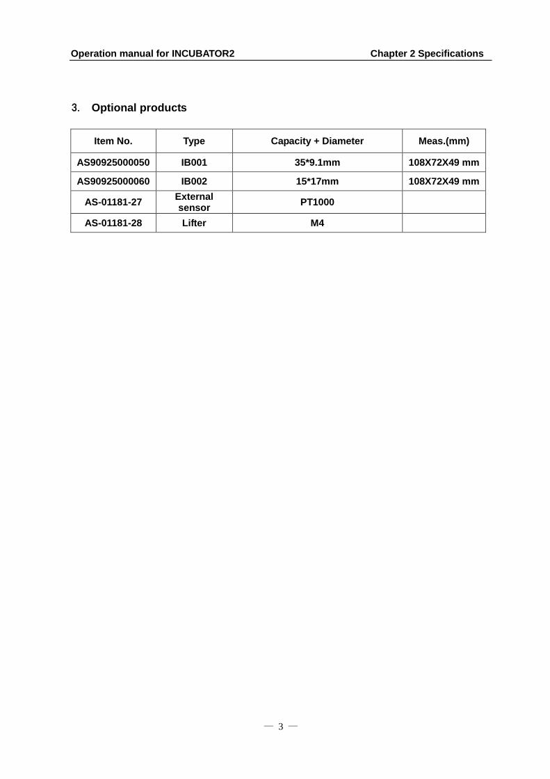
3. Optional products
Item No. Type Capacity + Diameter Meas.(mm)
AS90925000050 IB001 35*9.1mm 108X72X49 mm
AS90925000060 IB002 15*17mm 108X72X49 mm
AS-01181-27 External sensor
PT1000
AS-01181-28 Lifter M4
Operation manual for INCUBATOR2 Chapter 3 Basic Instructions
— 4 —
Chapter 3 Basic Instructions
This chapter focuses on the introductions of the structure, keypads and key-functions of
the instrument, as well as preparatory work before starting. Please read this chapter
before starting when using this instrument for the first time.
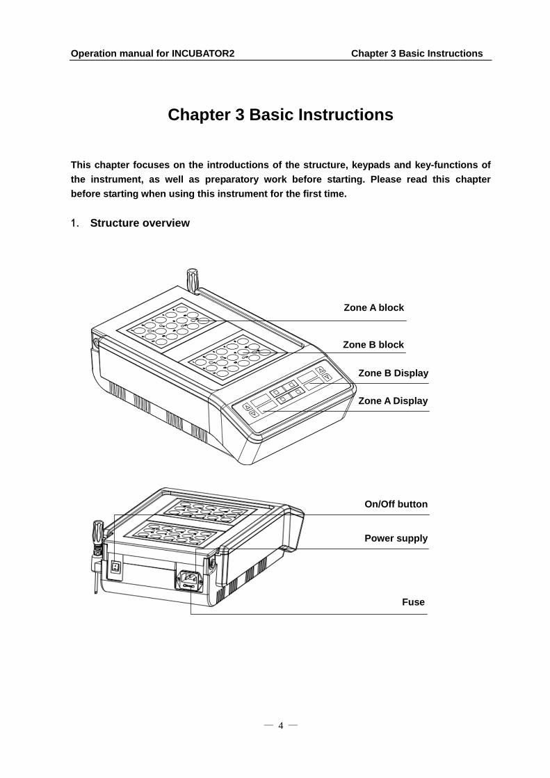
1. Structure overview
Zone A block
Power supply
plug
Fuse
On/Off button
Zone B block
Zone A Display
Zone B Display
Operation manual for INCUBATOR2 Chapter 3 Basic Instructions
— 5 —
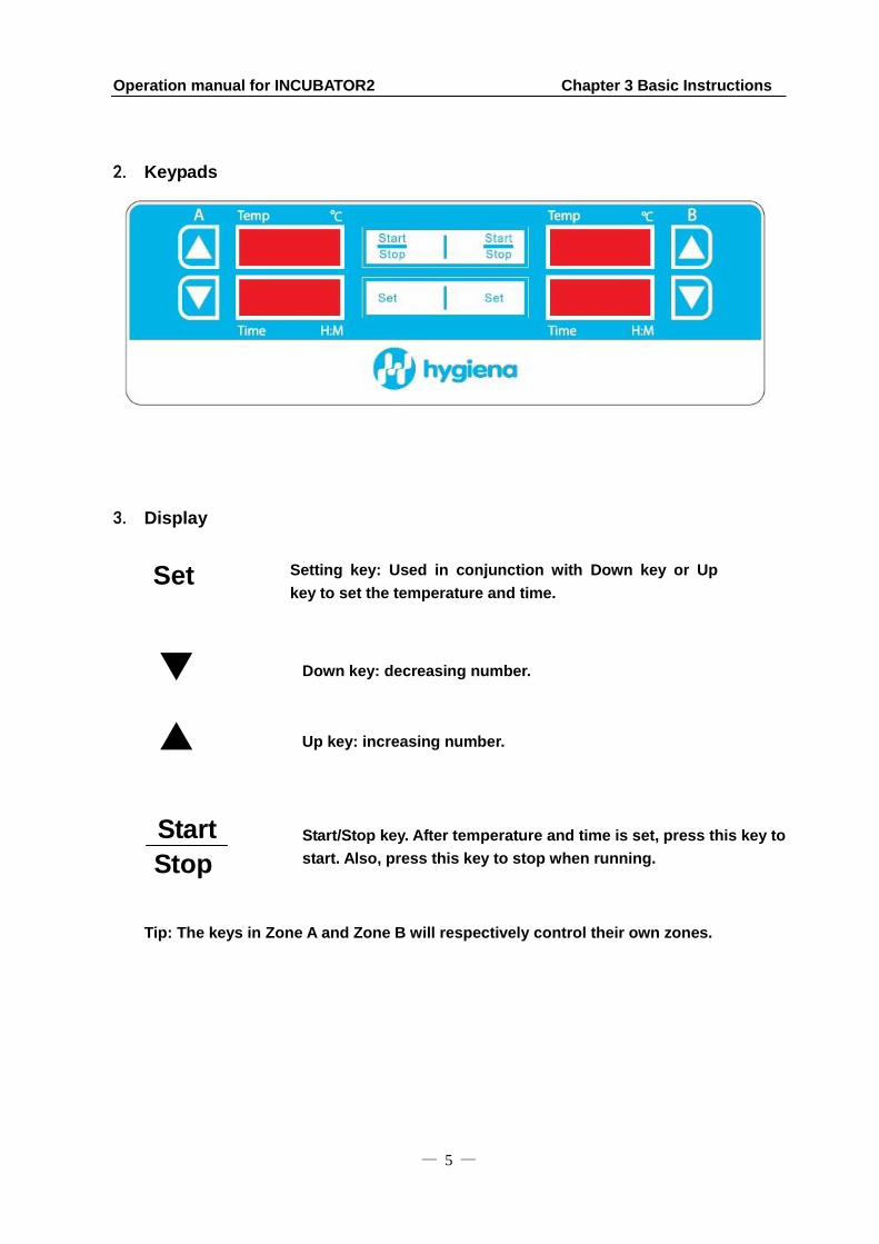
2. Keypads
3. Display
Set
Start
Tip: The keys in Zone A and Zone B will respectively control their own zones.
Down key: decreasing number.
Up key: increasing number.
Setting key: Used in conjunction with Down key or Up
key to set the temperature and time.
Start/Stop key. After temperature and time is set, press this key to
start. Also, press this key to stop when running. Stop

Operation manual for INCUBATOR2 Chapter 4 Operation Guide
— 6 —
Chapter 4 Operation Guide
1. Temperature and Time Setting
a) Press the On/Off button; the display flashes 3
times, the instrument goes into the initial
state with the sound of “beep”.
b) After about 3 seconds, the temperature
automatically goes up to the setting
temperature. For example, in the diagram to
the right: The 28.5 in display is the real-time
temperature of the block (It indicates that the
temperature now is 28.5°C). The 00:35 in
display is the running time set previously. (It
indicates that the running time is 35min).
c) Press “Set” key, then release immediately.
The displayed temperature is the value set at
last use. For example, in the diagrams to the
right: The flashing digit indicates that it can be
modified. Press or to modify the
temperature.
d) Press “Set” key again, then release
immediately. The displayed time is the value
set at last use. For example, in the diagram to
the right: 00:35(35min) decimal digits in
rightmost position flash. The digit flashing
indicates that it can be modified. Press or
to modify the time.
Operation manual for INCUBATOR2 Chapter 4 Operation Guide
— 7 —
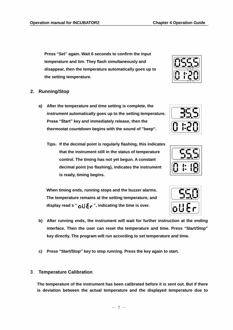
Press “Set” again. Wait 6 seconds to confirm the input
temperature and tim. They flash simultaneously and
disappear, then the temperature automatically goes up to
the setting temperature.
2. Running/Stop
a) After the temperature and time setting is complete, the
instrument automatically goes up to the setting temperature.
Press “Start” key and immediately release, then the
thermostat countdown begins with the sound of "beep".
Tips:If the decimal point is regularly flashing, this indicates
that the instrument still in the status of temperature
control. The timing has not yet begun. A constant
decimal point (no flashing), indicates the instrument
is ready, timing begins.
When timing ends, running stops and the buzzer alarms.
The temperature remains at the setting temperature, and
display read s “ ”, indicating the time is over.
b) After running ends, the instrument will wait for further instruction at the ending
interface. Then the user can reset the temperature and time. Press “Start/Stop”
key directly. The program will run according to set temperature and time.
c) Press “Start/Stop” key to stop running. Press the key again to start.
3. Temperature Calibration
The temperature of the instrument has been calibrated before it is sent out. But if there
is deviation between the actual temperature and the displayed temperature due to
Operation manual for INCUBATOR2 Chapter 4 Operation Guide
— 8 —
some reason, the user can do as follows to correct the error. There are 2 testing tools
for this instrument to do temperature calibration: 1. By thermostat, 2. By External
sensor. (External sensor is an optional part which needs to be ordered separately.)
Caution: the instrument uses double temperature adjustment to ensure its veracity.
This means that it is linearly adjusted on two points. The temperature veracity
will be within ±0.5 after the double temperatures adjustment. Both the
ambient temperature and the block temperature should be lower than 35.
3.1. Thermometer Calibration Instructions:
a) After the startup of the instrument, make sure the temperature in display is below 35
°C. If the temperature is higher than 35 °C, wait until the temperature is below 35°C.
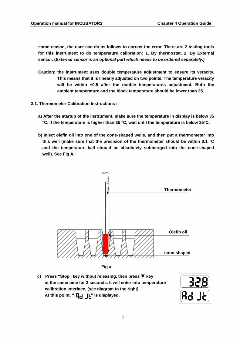
b) Inject olefin oil into one of the cone-shaped wells, and then put a thermometer into
this well (make sure that the precision of the thermometer should be within 0.1 °C
and the temperature ball should be absolutely submerged into the cone-shaped
well). See Fig A.
c) Press “Stop” key without releasing, then press key
at the same time for 3 seconds. It will enter into temperature
calibration interface, (see diagram to the right).
At this point, “ ” is displayed.
Fig a
Thermometer
Olefin oil
cone-shaped
well

Operation manual for INCUBATOR2 Chapter 4 Operation Guide
— 9 —
The temperature displayed is current temperature and begins to rise to 40.0°C
automatically.
When the temperature reaches 40.0°C constant
temperature, the decimal digit begins to flicker, waiting
for the calibrated value of 40.0°C. Read out the actual
value from the thermometer after 20 minutes.
Notes: Please read the actual value after 20 minutes’ constant
temperature to ensure the calibration accuracy.
For example: If the actual read out of thermometer is 39.6°C,
modify the temperature to 39.6 by pressing or . Then press
“Start/Stop” to confirm the input value.
d) Next the instrument will heat to 100°C automatically. Repeat above steps.
Notes: Please input the actual value after 20 minutes’ constant temperature to ensure
calibration accuracy.
For example: If the actual readout is 101.5°C, modify the temperature
in display to 101.5 by pressing or . Then press “Start/Stop” to
confirm the input value.
Use the same method to calibrate the temperature deviation both zones.
Notes: Pressing “Set” and “” simultaneously during the temperature calibration will
exit the temperature calibration program. The changed value will have no
effect.
3.2. External Sensor Calibration Instructions:
a) After the startup of the instrument, make sure the temperature in display is below
35°C. If the temperature is higher than 35°C, wait until the temperature is below 35°C.
b) Put External sensor into a block well. See Fig b.

Operation manual for INCUBATOR2 Chapter 4 Operation Guide
— 10 —
c) Press “Set” key without releasing, then press “Start/Stop” key
at the same time for 3 seconds. It will enter into temperature
calibration interface, (see diagram to the right.) At this point,
“ ” is displayed, which indicates it is in external
temperature calibration mode. The temperature displayed is
the external sensor’s current temperature and it begins to rise
to 40.0°C automatically.
It will automatically display “ ” six seconds later.
The upper displayed 32.0 is the current temperature of
the External sensor.
When the temperature reaches to 40°C constant temperature,
the decimal digit begins to flicker, waiting for the calibrated
value of 40°C. After incubating 20mins, the user can make
the calibration.
Notes: Please read the actual value after 20 minutes’
constant temperature to ensure the calibration accuracy.
Fig b
Operation manual for INCUBATOR2 Chapter 4 Operation Guide
— 11 —
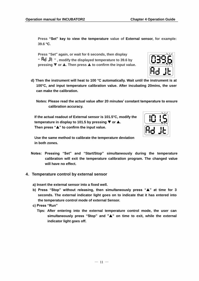
Press “Set” key to view the temperature value of External sensor, for example:
39.6 °C.
Press “Set” again, or wait for 6 seconds, then display
“
” , modify the displayed temperature to 39.6 by
pressing or . Then press to confirm the input value.
d) Then the instrument will heat to 100 °C automatically. Wait until the instrument is at
100°C, and input temperature calibration value. After incubating 20mins, the user
can make the calibration.
Notes: Please read the actual value after 20 minutes’ constant temperature to ensure
calibration accuracy.
If the actual readout of External sensor is 101.5°C, modify the
temperature in display to 101.5 by pressing or .
Then press “” to confirm the input value.
Use the same method to calibrate the temperature deviation
in both zones.
Notes: Pressing “Set” and “Start/Stop” simultaneously during the temperature
calibration will exit the temperature calibration program. The changed value
will have no effect.
4.Temperature control by external sensor
a) Insert the external sensor into a fixed well.
b) Press “Stop” without releasing, then simultaneously press “” at time for 3
seconds. The external indicator light goes on to indicate that it has entered into
the temperature control mode of external Sensor.
c) Press “Run”
Tips: After entering into the external temperature control mode, the user can
simultaneously press “Stop” and "" on time to exit, while the external
indicator light goes off.

Operation manual for INCUBATOR2 Chapter 4 Operation Guide
— 12 —
5.The exchange of metal block
a) Completely screw out the 2 screws which
secure the metal blocks by turning
wrench in an counterclockwise direction.
b) Fix the wrench in the center well of the block.
c) Pull out the wrench with the block.

Operation manual for INCUBATOR2 Chapter 4 Operation Guide
— 13 —
d) Screw the wrench out of the block, and fix it to another block. Then put it onto the
instrument. Remove the wrench from the block, then secure the block with 2
screws.
Operation manual for INCUBATOR2 Chapter 5 Failure Analysis and Troubleshooting
— 14 —
Chapter 5 Failure Analysis and Troubleshooting
Problems and actions
No. Common problem Possible cause Action(s)
1 No display on the screen
No power on the main power plug
Check power supply and plug for damage, proper installation
Faulty fuse Change fuse
On/Off button broken Change button
Others Contact the supplier
2 The actual and displayed temperatures are quite different
Broken sensor or loose contact of the block
Ensure block is secured with screws
Contact the supplier
3
“OPEn” displayed, alarming “beep”
Sensor disconnect
Contact the supplier “SHOr” displayed, alarming “beep”
Sensor short-circuit
“HHHH” displayed, alarming “beep”
Sensor broken, or block temperature is too high
4 No heating Sensor broken
Contact the supplier Heating tube broken
5 Keys don’t work Faulty key Contact the supplier
Operation manual for INCUBATOR2 Appendix
— 15 —
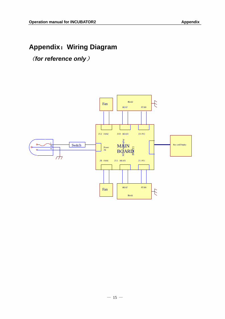
Appendix:Wiring Diagram
(for reference only)
KE
Y a
nd D
ispl
ay
PT1
Power
HEAT1
HEAT2 PT2
MAINBOARD
FAN2
FAN1
Key and DisplayL
PE
N
HEAT PT100
Block1
HEAT PT100
Block2
Fan
Fan
Switch
PO
RT
1J3J12
J1J8
J6
J10
J11

Memo