index gage block gage blocks - · pdf fileperfect wringing is possible using the center hole....
TRANSCRIPT
CERA/Steel Combination Gage Block Sets
Step Master
ZERO CERA BLOCK
Ceramic Straight Master
E-1
Small Tool Instruments and Data Management
Gage Block
Reference Gages
Granite Surface Plates & Bench Comparator
INDEXGage Blocks E-2-4Metric Rectangular Gage Block Set E-5,6Inch Rectangular Gage Block Set E-7Micrometer Inspection Gage Block Sets E-8Individual Metric Rectangular Gage Block E-9,10Individual Inch Rectangular Gage Block E-11Rectangular Gage Block with CTE E-12Rectangular Gage Block Accessories E-13-15Metric Square Gage Block Set E-16Inch Square Gage Block Set E-17Individual Metric Square Gage Block E-18Individual Inch Square Gage Block E-19Square Gage Block Accessories E-20,21Ceraston E-22Maintenance Kit for Gage Block E-22Step Master E-23Made-to-order Block & Reference E-23Gage Block Comparator GBCD-250 E-24Gage Block Comparator GBCD-100A E-24Height Masters E-25Digital Height Master E-26Riser Blocks E-27Auxiliary Block Kit E-27Universal Height Master E-28High Accuracy Check Master HMC-H E-29CERA Straight Master SM-C E-30Square Master E-31Reference GagesStandard Scales E-32Working Standard Scales E-32Steel Squares E-33High Precision Square E-33Knife Edge Straight Edge E-34Spring Dividers and Calipers E-34Combination Square Set E-35,36Double Square Set E-36Steel Rules E-37,38Semi-Flexible Rules E-39Hook Rules E-39Pocket Steel Rule E-39Thickness Gages E-40Precision Levels E-40Digital Universal Protractor E-41Universal Bevel Protractor E-42Protractor E-43Bevel Protractor E-43Depth Gage, Adjustable Angle E-44Zero-It E-44Zero-Setter E-44Angle Gages E-45Angle Blocks E-46Adjustable Parallels E-46Radius Gages E-47Pitch Gages E-47Radius Gages-Sets E-48Standard Gages E-49Tap and Drill Gage E-49Drill Point Gage E-49Thread Gage E-49Center Gage E-50
Tap Wrench E-50Scribers E-51Center Punches E-51Drive Pin Punches E-51Center Finder E-52Pin Vises E-52Wiggler E-52Optical Center Punch E-52Edge & Center Finders E-53Bench Center E-53Digital Protractor E-54Digital Hand Tachometers E-55Granite Surface PlateGranite Surface Plate Accessories E-56Black Granite Surface Plate E-57Steel Stands E-58Bench Center E-55Digital Protractor E-56Digital Hand Tachometers E-57Datatorq E-58
E
Height Master
US-1002
E-2
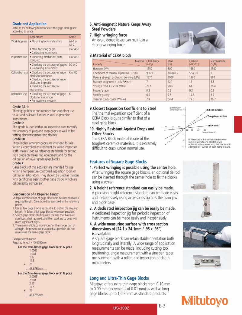
Resistance to wear Steel
Silicon nitride
Tungsten carbide
CERA Block
20000
0.2
0.4
(m)
4000 6000 8000
Abrasion loss
Amount of travel (m)
Gage BlockSERIES 516
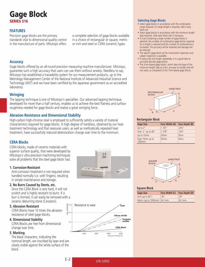
FEATURESPrecision gage blocks are the primary standards vital to dimensional quality control in the manufacture of parts. Mitutoyo offers
a complete selection of gage blocks available in a choice of rectangular or square, metric or inch and steel or CERA (ceramic) types.
CERA BlocksCERA blocks, made of ceramic materials with superior surface quality, that were developed by Mitutoyo’s ultra precision machining techniques solve all problems that the steel gage block had.
1. Corrosion-Resistant Anti-corrosion treatment is not required when
handled normally (i.e. with fingers), resulting in simple maintenance and storage.
2. No Burrs Caused by Dents, etc. Since the CERA Block is very hard, it will not
scratch and is highly resistant to burrs. If a burr is formed, it can easily be removed with a ceramic deburring stone (Ceraston).
3. Abrasion Resistant CERA Blocks have 10 times the abrasion
resistance of steel gage blocks.4. Dimensional Stability CERA Blocks are free from dimensional
change over time.5. Marking The black characters, indicating the
nominal length, are inscribed by laser and are clearly visible against the white surface of the block.
Selecting Gage Blocks• Selectgageblocksinaccordancewiththecombination
range required. If a large length is required, add a long block set.
• Selectgageblocksinaccordancewiththeminimumlengthstep required. Add wear block sets if necessary.
• Ifasetcontainingalargenumberofgageblocksisselected, the number of combination gage blocks required for a length is reduced and the number of combinations is increased. The accuracy will be retained and damage will be reduced.
• Thespecificgageblocksetformicrometerinspectionandcaliper inspection is available.
• Ifusingonlyonelengthrepeatedly,itisagoodideatopurchase discrete gage blocks.
• The2mm-basedgageblocks,whichtakethebaseoftheminimum length step as 2mm, are easy to handle and will not warp, as compared to the 1mm-based gage blocks.
AccuracyGage blocks offered by an all-round precision measuring machine manufacturer, Mitutoyo, guarantee such a high accuracy that users can use them without anxiety. Needless to say, Mitutoyo has established a traceability system for our measurement products, up to the Metrology Management Center of the National Institute of Advanced Industrial Science and Technology (AIST) and we have been certified by the Japanese government as an accredited laboratory.
WringingThe lapping technique is one of Mitutoyo’s specialties. Our advanced lapping technique, developed for more than a half century, enables us to achieve the best flatness and surface roughness needed for gage blocks and realize a great wringing force.
Abrasion Resistance and Dimensional StabilityHigh-carbon high-chrome steel is employed to sufficiently satisfy a variety of material characteristics required for gage blocks. A high degree of hardness, obtained by our heat treatment technology and that reassures users, as well as methodically repeated heat treatment, have successfully reduced deterioration change over time to the minimum.
Gage Size Face Width (A) Face Depth (B)Up to 2” 1.181” .355”Over .2” up to 40” 1.378” .355”Up to 10mm 30mm 9mmOver 10mm up to 1000mm
35mm 9mm
Gage Size Face Width (C) Face Depth (D)Inch (up to 40”) .95” .95”Metric (up to 1000mm) 24.1mm 24.1mm
Rectangular Block
Square Block
US-1002
E-3
3 Silicon nitride
Tungsten carbide
CERA Block
Differences in the dimension between some materials and steel that are obtained when measuring testpieces witha length of 100mm at each temperature.
2
1
19
20 21 22 23
1817
-1
-2
-3
Temperature (C)
Difference in dimension (m)
Grade and ApplicationRefer to the following table to select the gage block grade according to usage.
Grade AS-1: These gage blocks are intended for shop floor use to set and calibrate fixtures as well as precision instruments.Grade 0: This grade is used within an inspection area to verify the accuracy of plug and snap gages as well as for setting electronic measuring devices.Grade 00: These higher accuracy gages are intended for use within a controlled environment by skilled inspection staff. Mainly used as reference standards for setting high precision measuring equipment and for the calibration of lower grade gage blocks.Grade K: Gage blocks of this accuracy are intended for use within a temperature controlled inspection room or calibration laboratory. They should be used as masters with certificates against other gage blocks which are calibrated by comparison.
Combination of a Required LengthMultiple combinations of gage blocks can be used to make a
required length. Care should be exercised in the following points.
1. Use as few gage blocks as possible to obtain the required length. (= Select thick gage blocks whenever possible.)
2. Select gage blocks starting with the one that has least significant digit required, and then work up to ones with more significant digits.
3. There are multiple combinations for the integer part of a length. To prevent wear as much as possible, do not always use the same gage blocks.
Example combinationRequired length = 45.6785mm
For the 1mm-based gage block set (112 pcs.) 1.0005 1.008 1.17 17.5 + 25
45.6785mm
For the 2mm-based gage block set (112 pcs.) 2.0005 2.008 2.17 14.5 + 25
45.6785mm
8. Material of CERA blockMaterial
PropertyCERA Block(ZrO2)
Steel (Fe)
Carbide (WC-Co)
Silicon nitride (Si3N4)
Hardness (HV) 1350 800 1650 1500Coefficient of thermal expansion (10-6/K) 9.3±0.5 10.8±0.5 5.5±1.0 2Flexural strength by 3-point bending (MPa) 1270 1960 1960 580FracturetoughnessK1c(MPa•m1/2) 7 120 12 6.5Young’s modulus x104 (MPa) 20.6 20.6 61.8 28.4Poisson’s ratio 0.3 0.3 0.2 0.3Specific gravity 6.0 7.8 14.8 3.2Thermalconductivity(W/m•k) 2.9 54.4 79.5 16.7
Features of Square Gage Blocks1. Perfect wringing is possible using the center hole.
After wringing the square gage blocks, an optional tie rod can be inserted through the center hole to fix the blocks using a screw.
2. A height reference standard can easily be made. A precision height reference standard can be made easily and inexpensively using accessories such as the plain jaw and block base.
3. A dedicated inspection jig can be easily be made. A dedicated inspection jig for periodic inspection of instruments can be made easily and inexpensively.
4. A wide measuring surface with cross section dimensions of [24.1 x 24.1mm / .95 x .95”] is available. A square gage block can retain stable orientation both longitudinally and laterally. A wide range of application measurements can be made, including cutting tool positioning, angle measurement with a sine bar, taper measurement with a roller, and inspection of depth micrometers.
Long and Ultra-Thin Gage BlocksMitutoyo offers extra thin gage blocks from 0.10 mm to 0.99 mm (increments of 0.01 mm) as well as long gage blocks up to 1,000 mm as standard products.
Applications GradeWorkshop use •Mountingtoolsandcutters AS-1 or
AS-2•Manufacturinggages•Calibratinginstruments
0 or AS-1
Inspection use •Inspectingmechanicalparts,tools, etc.
0 or AS-1
•Checkingtheaccuracyofgages•Calibratinginstruments
00 or 0
Calibration use •Checkingtheaccuracyofgageblocks for workshop•Checkingtheaccuracyofgageblocks for inspection•Checkingtheaccuracyofinstruments
K or 00
Reference use •Checkingtheaccuracyofgageblocks for calibration•Foracademicresearch
K
9. Closest Expansion Coefficient to Steel The thermal expansion coefficient of a CERA Block is quite similar to that of a steel gage block.
10. Highly Resistant Against Drops and Other Shocks The CERA Block material is one of the toughest ceramics materials. It is extremely difficult to crack under normal use.
6. Anti-magnetic Nature Keeps Away Steel Powders
7. High wringing force An even, dense tissue can maintain a
strong wringing force.
US-1002
E-4
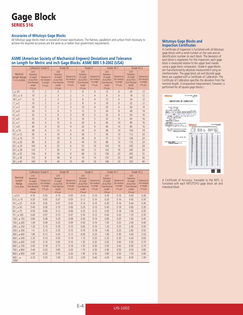
Mitutoyo Gage Blocks and Inspection CertificatesA Certificate of Inspection is furnished with all Mitutoyo gage blocks with a serial number on the case and an identification number on each block. The deviation of each block is registered. For this inspection, each gage block is measured relative to the upper level master using a gage block comparator. Grade K gage blocks are manufactured by absolute measurement using an interferometer. The gage block set and discrete gage block are supplied with a Certificate of Calibration. The Certificate of Calibration specifies the deviation from the nominal length. (Comparative measurement, however, is performed for all square gage blocks.)
Accuracies of Mitutoyo Gage BlocksAll Mitutoyo gage blocks meet or exceed all known specifications. The flatness, parallelism and surface finish necessary to achieve the required accuracies are the same as or better than government requirements.
ASME (American Society of Mechanical Engeers) Deviations and Tolerance on Length for Metric and inch Gage Blocks: ASME B89.1.9-2002 (USA)
Nominal Length Range l n in inches
Calibration Grade K Grade 00 Grade 0 Grade AS-1 Grade AS-2Limit
Deviations of Length
at any Point From Nominal
Length ± te µin.
Tolerance for the Variation
In Length ± tv µin.
Limit Deviations of Length
at any Point From Nominal
Length ± te µin.
Tolerance for the Variation
In Length ± tv µin.
Limit Deviations of Length
at any Point From Nominal
Length ± te µin.
Tolerance for the Variation
In Length ± tv µin.
Limit Deviations of Length
at any Point From Nominal
Length ± te µin.
Tolerance for the Variation
In Length ± tv µin.
Limit Deviations of Length
at any Point From Nominal
Length ± te µin.
Tolerance for the Variation
In Length ± tv µin.
ln ≤ .05 12 2 4 2 6 4 12 6 24 12
.05 ln ≤ .4 10 2 3 2 5 4 8 6 18 12
.45 ln ≤ 1 12 2 3 2 6 4 12 6 24 12
1 ln ≤ 2 16 2 4 2 8 4 16 6 32 12
2 ln ≤ 3 20 2 5 3 10 4 20 6 40 14
3 ln ≤ 4 24 3 6 3 12 5 24 8 48 14
4 ln ≤ 5 32 3 8 3 16 5 32 8 64 16
5 ln ≤ 6 32 3 8 3 16 5 32 8 64 16
6 ln ≤ 7 40 4 10 4 20 6 40 10 80 16
7 ln ≤ 8 40 4 10 4 20 6 40 10 80 16
8 ln ≤ 10 48 4 12 4 24 6 48 10 104 18
10 ln ≤ 12 56 4 14 4 28 7 56 10 112 20
12 ln ≤ 16 72 5 18 5 36 8 72 12 144 20
16 ln ≤ 20 88 6 20 6 44 10 88 14 176 24
20 ln ≤ 24 104 6 25 6 52 10 104 16 200 28
24 ln ≤ 28 120 7 30 7 60 12 120 18 240 28
28 ln ≤ 32 136 8 34 8 68 12 136 20 260 32
32 ln ≤ 36 152 8 38 8 76 14 152 20 300 36
36 ln ≤ 40 160 10 40 10 80 16 168 24 320 40
Gage BlockSERIES 516
Nominal Length Range
l n in mm
Calibration Grade K Grade 00 Grade 0 Grade AS-1 Grade AS-2Limit
Deviations of Length
at any Point From Nominal
Length ± te µm
Tolerance for the Variation
In Length ± tv µm
Limit Deviations of Length
at any Point From Nominal
Length ± te µm
Tolerance for the Variation
In Length ± tv µm
Limit Deviations of Length
at any Point From Nominal
Length ± te µm
Tolerance for the Variation
In Length ± tv µm
Limit Deviations of Length
at any Point From Nominal
Length ± te µm
Tolerance for the Variation
In Length ± tv µm
Limit Deviations of Length
at any Point From Nominal
Length ± te µm
Tolerance for the Variation
In Length ± tv µm
ln ≤ 0.5 0.30 0.05 0.10 0.05 0.14 0.10 0.30 0.16 0.60 0.30
0.5 ln ≤ 10 0.20 0.05 0.07 0.05 0.12 0.10 0.20 0.16 0.45 0.30
10 ln ≤ 25 0.30 0.05 0.07 0.05 0.14 0.10 0.30 0.16 0.60 0.30
25 ln ≤ 50 0.40 0.06 0.10 0.06 0.20 0.10 0.40 0.18 0.80 0.30
50 ln ≤ 75 0.50 0.06 0.12 0.06 0.25 0.12 0.50 0.18 1.00 0.35
75 ln ≤ 100 0.60 0.07 0.15 0.07 0.30 0.12 0.60 0.20 1.20 0.35
100 ln ≤ 150 0.80 0.08 0.20 0.08 0.40 0.14 0.80 0.20 1.60 0.40
150 ln ≤ 200 1.00 0.09 0.25 0.09 0.50 0.16 1.00 0.25 2.00 0.40
200 ln ≤ 250 1.20 0.10 0.30 0.10 0.60 0.16 1.20 0.25 2.40 0.45
250 ln ≤ 300 1.4 0.10 0.35 0.10 0.70 0.18 1.40 0.25 2.80 0.50
300 ln ≤ 400 1.80 0.12 0.45 0.12 0.90 0.20 1.80 0.30 3.60 0.50
400 ln ≤ 500 2.20 0.14 0.50 0.14 1.10 0.25 2.20 0.35 4.40 0.60
500 ln ≤ 600 2.60 0.16 0.65 0.16 1.30 0.25 2.60 0.40 5.00 0.70
600 ln ≤ 700 3.00 0.18 0.75 0.18 1.50 0.30 3.00 0.45 6.00 0.70
700 ln ≤ 800 3.40 0.20 0.85 0.20 1.70 0.30 3.40 0.50 6.50 0.80
800 ln ≤ 900 3.80 0.20 0.95 0.20 1.90 0.35 3.80 0.50 7.50 0.90
900 l n ≤
10004.20 0.25 1.00 0.25 2.00 0.40 4.20 0.60 8.00 1.00
A Certificate of Accuracy, traceable to the NIST, is furnished with each MITUTOYO gage block set and individual block
US-1002
E-5
Provided with Inspection Certificate
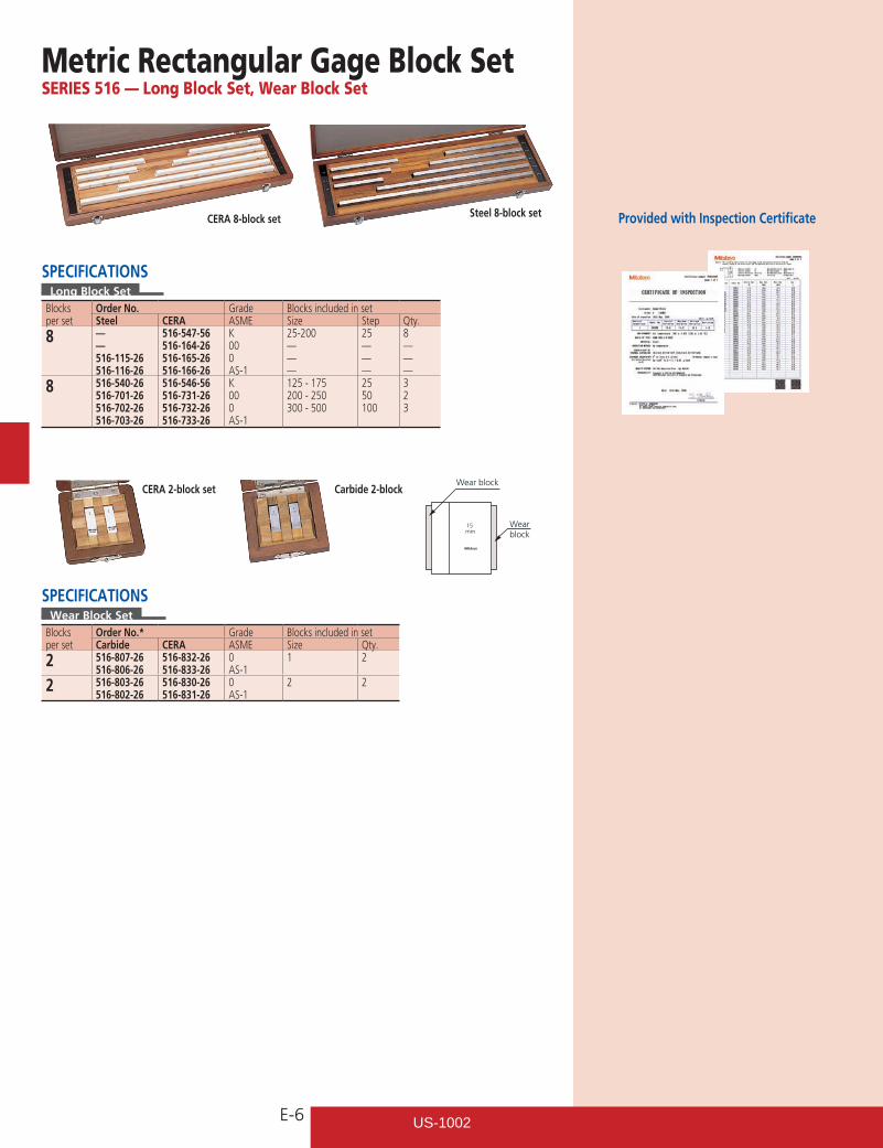
Metric Rectangular Gage Block SetSERIES 516 — 1mm Base Block Set
Steel 112-block set Steel 103-block set Steel 47-block set
CERA 112-block set CERA 56-block set
SPECIFICATIONS 1mm Base Bock Set
Blocks per set
Order No.Grade
Blocks included in setSteel CERA Size Step Qty.
112 516-531-56516-937-26516-938-26516-939-26516-940-26
516-541-56516-337-26516-338-26516-339-26516-340-26
K000AS-1AS-2
1.00051.001 - 1.0091.01 - 1.490.5 - 24.525 - 100
0.0010.010.525
1949494
103 516-533-56516-941-26516-942-26516-943-26516-944-26
516-542-56516-341-26516-342-26516-343-26516-344-26
K000AS-1AS- 2
1.0051.01 - 1.490.5 - 24.525 - 100
0.010.525
149494
87 516-535-56516-945-26516-946-26516-947-26516-948-26
515-543-56516-345-26516-346-26516-347-26516-348-26
K000AS-1AS- 2
1.001 - 1.0091.01 - 1.490.5 - 9.510 - 100
0.0010.010.510
9491910
56 516-536-56516-953-26516-954-26516-955-26516-956-26
516-544-56516-353-26516-354-26516-355-26516-356-26
K000AS-1AS-2
0.51.001 - 1.0091.01 - 1.091.1 - 1.91 - 2425 - 100
0.0010.010.1125
1999244
47 516-537-56516-957-26516-958-26516-959-26516-960-26
516-545-56516-357-26516-358-26516-359-26516-360-26
K000AS-1AS-2
1.0051.01 - 1.091.1 - 1.91 - 2425 - 100
0.010.1125
199244
CERA/Steel combination 47-block set
US-1002
E-6
Provided with Inspection Certificate
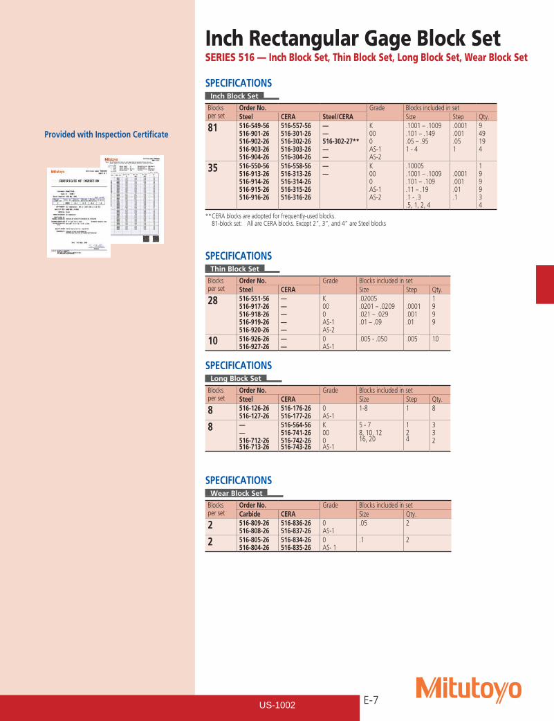
Wear block
Wearblock
15 mm
SPECIFICATIONSLong Block Set
Blocks per set
Order No. Grade Blocks included in setSteel CERA ASME Size Step Qty.
8 — — 516-115-26 516-116-26
516-547-56 516-164-26 516-165-26 516-166-26
K 00 0 AS-1
25-200 — — —
25 — — —
8 — — —
8 516-540-26516-701-26516-702-26516-703-26
516-546-56516-731-26516-732-26516-733-26
K000AS-1
125 - 175200 - 250300 - 500
2550100
323
SPECIFICATIONSWear Block Set
Blocks per set
Order No.* Grade Blocks included in setCarbide CERA ASME Size Qty.
2 516-807-26516-806-26
516-832-26516-833-26
0AS-1
1 2
2 516-803-26516-802-26
516-830-26516-831-26
0AS-1
2 2
Metric Rectangular Gage Block SetSERIES 516 — Long Block Set, Wear Block Set
Steel 8-block setCERA 8-block set
CERA 2-block set Carbide 2-block
US-1002
E-7
Provided with Inspection Certificate
Inch Rectangular Gage Block SetSERIES 516 — Inch Block Set, Thin Block Set, Long Block Set, Wear Block Set
SPECIFICATIONSInch Block Set
Blocks per set
Order No. Grade Blocks included in setSteel CERA Steel/CERA Size Step Qty.
81 516-549-56516-901-26516-902-26516-903-26516-904-26
516-557-56516-301-26516-302-26516-303-26516-304-26
——516-302-27**——
K000AS-1AS-2
.1001 – .1009
.101 – .149
.05 – .951 - 4
.0001
.001
.051
949194
35 516-550-56516-913-26516-914-26516-915-26516-916-26
516-558-56516-313-26516-314-26516-315-26516-316-26
——
K000AS-1AS-2
.10005
.1001 – .1009
.101 – .109
.11 – .19
.1 - .3
.5, 1, 2, 4
.0001
.001
.01
.1
199934
** CERA blocks are adopted for frequently-used blocks. 81-block set: All are CERA blocks. Except 2”, 3”, and 4” are Steel blocks
SPECIFICATIONSThin Block Set
Blocks per set
Order No. Grade Blocks included in setSteel CERA Size Step Qty.
28 516-551-56516-917-26516-918-26516-919-26516-920-26
—————
K000AS-1AS-2
.02005
.0201 – .0209
.021 – .029
.01 – .09
.0001
.001
.01
1999
10 516-926-26516-927-26
——
0AS-1
.005 - .050 .005 10
SPECIFICATIONSLong Block Set
Blocks per set
Order No. Grade Blocks included in setSteel CERA Size Step Qty.
8 516-126-26 516-127-26
516-176-26 516-177-26
0AS-1
1-8 1 8
8 ——516-712-26516-713-26
516-564-56516-741-26516-742-26516-743-26
K000AS-1
5 - 78, 10, 1216, 20
124
332
SPECIFICATIONSWear Block Set
Blocks per set
Order No. Grade Blocks included in setCarbide CERA Size Qty.
2 516-809-26516-808-26
516-836-26516-837-26
0AS-1
.05 2
2 516-805-26516-804-26
516-834-26516-835-26
0AS- 1
.1 2
US-1002
E-8
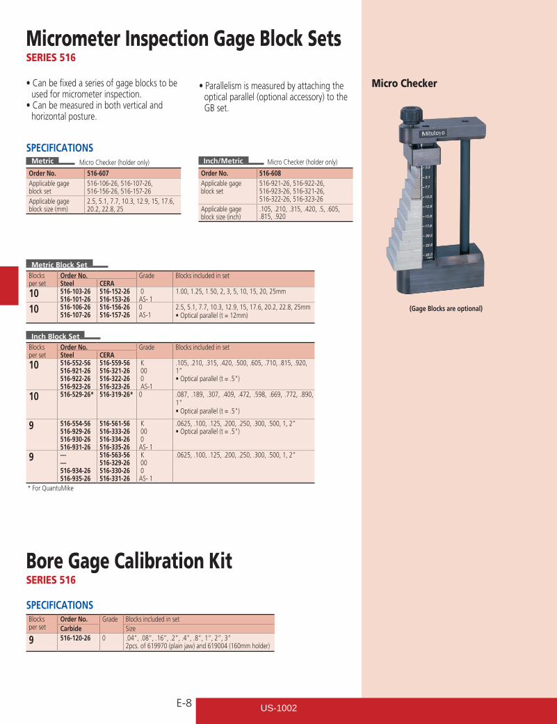
Micrometer Inspection Gage Block SetsSERIES 516
Micro Checker•Canbefixedaseriesofgageblockstobeused for micrometer inspection.•Canbemeasuredinbothverticaland
horizontal posture.
SPECIFICATIONSMetric
Order No. 516-607Applicable gage block set
516-106-26, 516-107-26, 516-156-26, 516-157-26
Applicable gage block size (mm)
2.5, 5.1, 7.7, 10.3, 12.9, 15, 17.6, 20.2, 22.8, 25
Inch/Metric
Order No. 516-608Applicable gage block set
516-921-26, 516-922-26, 516-923-26, 516-321-26, 516-322-26, 516-323-26
Applicable gage block size (inch)
.105, .210, .315, .420, .5, .605,
.815, .920
Metric Block SetBlocks per set
Order No. Grade Blocks included in setSteel CERA
10 516-103-26516-101-26
516-152-26516-153-26
0AS- 1
1.00, 1.25, 1.50, 2, 3, 5, 10, 15, 20, 25mm
10 516-106-26516-107-26
516-156-26516-157-26
0AS-1
2.5, 5.1, 7.7, 10.3, 12.9, 15, 17.6, 20.2, 22.8, 25mm•Opticalparallel(t=12mm)
(Gage Blocks are optional)
Inch Block SetBlocks per set
Order No. Grade Blocks included in setSteel CERA
10 516-552-56516-921-26516-922-26516-923-26
516-559-56516-321-26516-322-26516-323-26
K 00 0 AS-1
.105, .210, .315, .420, .500, .605, .710, .815, .920, 1”•Opticalparallel(t=.5")
10 516-529-26* 516-319-26* 0 .087, .189, .307, .409, .472, .598, .669, .772, .890, 1"•Opticalparallel(t=.5")
9 516-554-56516-929-26516-930-26516-931-26
516-561-56516-333-26516-334-26516-335-26
K 00 0AS- 1
.0625, .100, .125, .200, .250, .300, .500, 1, 2”•Opticalparallel(t=.5")
9 —— 516-934-26516-935-26
516-563-56516-329-26516-330-26516-331-26
K 00 0AS- 1
.0625, .100, .125, .200, .250, .300, .500, 1, 2”
SPECIFICATIONSBlocks per set
Order No. Grade Blocks included in setCarbide Size
9 516-120-26 0 .04”, .08”, .16”, .2”, .4”, .8”, 1”, 2”, 3” 2pcs. of 619970 (plain jaw) and 619004 (160mm holder)
Bore Gage Calibration KitSERIES 516
Micro Checker (holder only) Micro Checker (holder only)
•Parallelismismeasuredbyattachingtheoptical parallel (optional accessory) to the GB set.
* For QuantuMike
US-1002
E-9
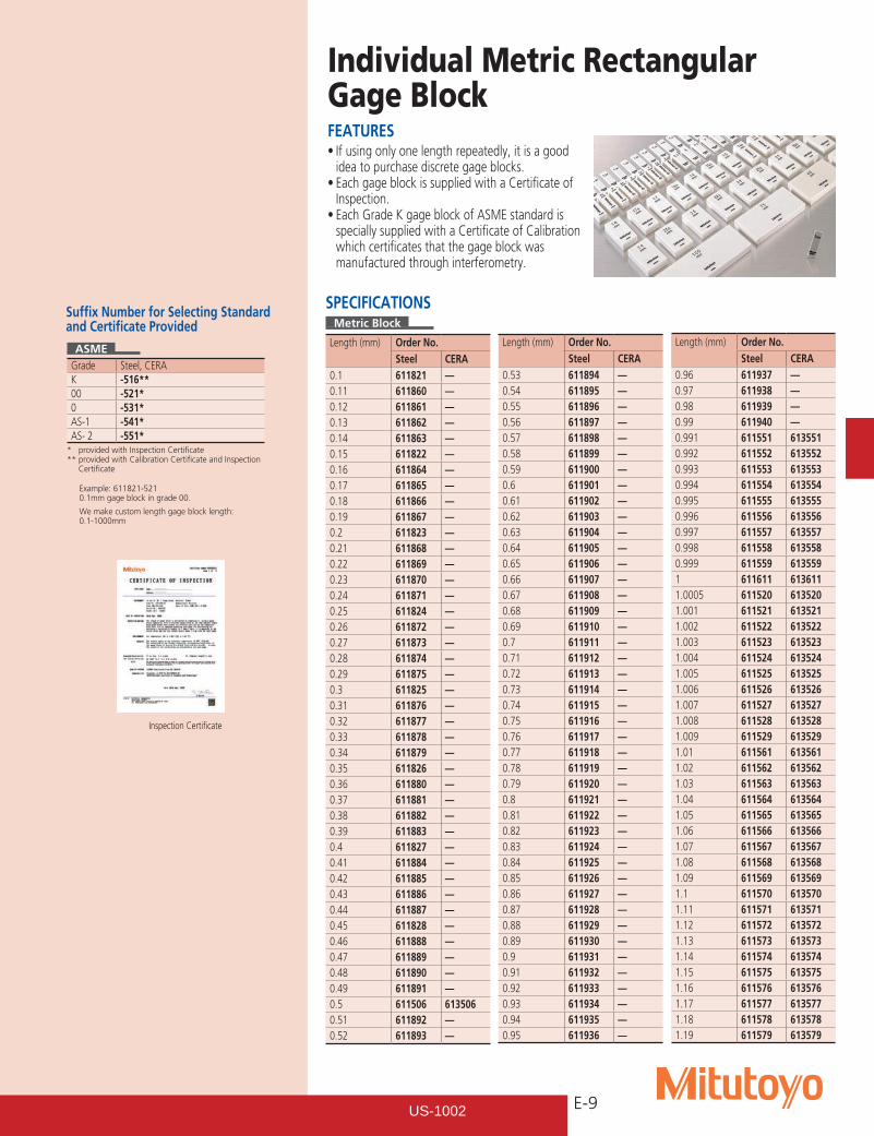
FEATURES•Ifusingonlyonelengthrepeatedly,itisagood
idea to purchase discrete gage blocks.•EachgageblockissuppliedwithaCertificateof
Inspection.•EachGradeKgageblockofASMEstandardis
specially supplied with a Certificate of Calibration which certificates that the gage block was manufactured through interferometry.
Individual Metric Rectangular Gage Block
SPECIFICATIONSMetric Block
Length (mm) Order No.Steel CERA
0.1 611821 —0.11 611860 —0.12 611861 —0.13 611862 —0.14 611863 —0.15 611822 —0.16 611864 —0.17 611865 —0.18 611866 —0.19 611867 —0.2 611823 —0.21 611868 —0.22 611869 —0.23 611870 —0.24 611871 —0.25 611824 —0.26 611872 —0.27 611873 —0.28 611874 —0.29 611875 —0.3 611825 —0.31 611876 —0.32 611877 —0.33 611878 —0.34 611879 —0.35 611826 —0.36 611880 —0.37 611881 —0.38 611882 —0.39 611883 —0.4 611827 —0.41 611884 —0.42 611885 —0.43 611886 —0.44 611887 —0.45 611828 —0.46 611888 —0.47 611889 —0.48 611890 —0.49 611891 —0.5 611506 6135060.51 611892 —0.52 611893 —
Length (mm) Order No.Steel CERA
0.53 611894 —0.54 611895 —0.55 611896 —0.56 611897 —0.57 611898 —0.58 611899 —0.59 611900 —0.6 611901 —0.61 611902 —0.62 611903 —0.63 611904 —0.64 611905 —0.65 611906 —0.66 611907 —0.67 611908 —0.68 611909 —0.69 611910 —0.7 611911 —0.71 611912 —0.72 611913 —0.73 611914 —0.74 611915 —0.75 611916 —0.76 611917 —0.77 611918 —0.78 611919 —0.79 611920 —0.8 611921 —0.81 611922 —0.82 611923 —0.83 611924 —0.84 611925 —0.85 611926 —0.86 611927 —0.87 611928 —0.88 611929 —0.89 611930 —0.9 611931 —0.91 611932 —0.92 611933 —0.93 611934 —0.94 611935 —0.95 611936 —
Length (mm) Order No.Steel CERA
0.96 611937 —0.97 611938 —0.98 611939 —0.99 611940 —0.991 611551 6135510.992 611552 6135520.993 611553 6135530.994 611554 6135540.995 611555 6135550.996 611556 6135560.997 611557 6135570.998 611558 6135580.999 611559 6135591 611611 6136111.0005 611520 6135201.001 611521 6135211.002 611522 6135221.003 611523 6135231.004 611524 6135241.005 611525 6135251.006 611526 6135261.007 611527 6135271.008 611528 6135281.009 611529 6135291.01 611561 6135611.02 611562 6135621.03 611563 6135631.04 611564 6135641.05 611565 6135651.06 611566 6135661.07 611567 6135671.08 611568 6135681.09 611569 6135691.1 611570 6135701.11 611571 6135711.12 611572 6135721.13 611573 6135731.14 611574 6135741.15 611575 6135751.16 611576 6135761.17 611577 6135771.18 611578 6135781.19 611579 613579
Suffix Number for Selecting Standard and Certificate Provided
ASMEGrade Steel, CERAK -516**00 -521*0 -531*AS-1 -541*AS- 2 -551*
* provided with Inspection Certificate** provided with Calibration Certificate and Inspection Certificate
Inspection Certificate
Example: 611821-5210.1mm gage block in grade 00.
We make custom length gage block length: 0.1-1000mm
US-1002
E-10
Length (mm) Order No.Steel CERA
1.2 611580 6135801.21 611581 6135811.22 611582 6135821.23 611583 6135831.24 611584 6135841.25 611585 6135851.26 611586 6135861.27 611587 6135871.28 611588 6135881.29 611589 6135891.3 611590 6135901.31 611591 6135911.32 611592 6135921.33 611593 6135931.34 611594 6135941.35 611595 6135951.36 611596 6135961.37 611597 6135971.38 611598 6135981.39 611599 6135991.4 611600 6136001.41 611601 6136011.42 611602 6136021.43 611603 6136031.44 611604 6136041.45 611605 6136051.46 611606 6136061.47 611607 6136071.48 611608 6136081.49 611609 6136091.5 611641 6136411.6 611516 6135161.7 611517 6135171.8 611518 6135181.9 611519 6135192 611612 6136122.0005 611690 —2.001 611691 —2.002 611692 —2.003 611693 —2.004 611694 —2.005 611695 —2.006 611696 —2.007 611697 —2.008 611698 —2.009 611699 —2.01 611701 —2.02 611702 —2.03 611703 —2.04 611704 —2.05 611705 —2.06 611706 —2.07 611707 —2.08 611708 —2.09 611709 —2.1 611710 —2.11 611711 —2.12 611712 —2.13 611713 —2.14 611714 —2.15 611715 —2.16 611716 —
Length (mm) Order No.Steel CERA
2.17 611717 —2.18 611718 —2.19 611719 —2.2 611720 —2.21 611721 —2.22 611722 —2.23 611723 —2.24 611724 —2.25 611725 —2.26 611726 —2.27 611727 —2.28 611728 —2.29 611729 —2.3 611730 —2.31 611731 —2.32 611732 —2.33 611733 —2.34 611734 —2.35 611735 —2.36 611736 —2.37 611737 —2.38 611738 —2.39 611739 —2.4 611740 —2.41 611741 —2.42 611742 —2.43 611743 —2.44 611744 —2.45 611745 —2.46 611746 —2.47 611747 —2.48 611748 —2.49 611749 —2.5 611642 6136422.6 611750 —2.7 611751 —2.8 611752 —2.9 611753 —3 611613 6136133.5 611643 6136434 611614 6136144.5 611644 6136445 611615 6136155.1 611850 6138505.5 611645 6136456 611616 6136166.5 611646 6136467 611617 6136177.5 611647 6136477.7 611851 6138518 611618 6136188.5 611648 6136489 611619 6136199.5 611649 61364910 611671 61367110.3 611852 61385210.5 611650 61365011 611621 61362111.5 611651 61365112 611622 61362212.5 611652 61365212.9 611853 613853
Length (mm) Order No.Steel CERA
13 611623 61362313.5 611653 61365314 611624 61362414.5 611654 61365415 611625 61362515.5 611655 61365516 611626 61362616.5 611656 61365617 611627 61362717.5 611657 61365717.6 611854 61385418 611628 61362818.5 611658 61365819 611629 61362919.5 611659 61365920 611672 61367220.2 611855 61385520.5 611660 61366021 611631 61363121.5 611661 61366122 611632 61363222.5 611662 61366222.8 611856 61385623 611633 61363323.5 611663 61366324 611634 61363424.5 611664 61366425 611635 61363525.25 611754 61375430 611673 61367335 611755 61375540 611674 61367441.3 611857 61385745 611756 61375650 611675 61367560 611676 61367670 611677 61367775 611801 61380180 611678 61367890 611679 613679100 611681 613681125 611802 613802131.4 611858 613858150 611803 613803175 611804 613804200 611682 613682250 611805 613805300 611683 613683400 611684 613684500 611685 613685600 611840 —700 611841 —750 611842 —800 611843 —900 611844 —1000 611845 —
Metric Wear Block
Length (mm) Order No.Tungsten carbide
1 6126112 612612
mm 125
92123
mm
92123
mm
92123
92123
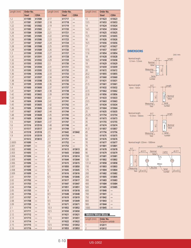
Length 9 -0.2 -0.05
9 -0.2 -0.05
9 -0.2 -0.05
Serial number
Nominal Value
Nominal Value
Nominal Value
Nominal Value
Serial number
Serial number
Measuring face
Measuring face
Measuring face
Measuring face
Serial number
9 -0.2 -0.05
35 -0.
3 0
35 -0.
3 0
30
-0.3
0
30 -0.
3 0
25 ± 0.525 ± 0.5
x0.211 x0.211
Length
Unit: mm
Length
Length
Airy line
2-Ø10
Nominal length 125mm - 1000mm
Nominal length: 10.3mm - 100mm
Nominal length: 6mm - 10mm
Nominal length: 0.1mm - 5.5mm
DIMENSIONS
US-1002
E-11
Individual Inch Rectangular Gage Block SPECIFICATIONS
Inch Block
Length (inch) Order No.Steel CERA
.004 611304 —
.005 611305 —
.006 611306 —
.007 611307 —
.008 611308 —
.009 611309 —
.01 611310 —
.011 611311 —
.012 611312 —
.013 611313 —
.014 611314 —
.015 611315 —
.016 611316 —
.017 611317 —
.018 611318 —
.019 611319 —
.02 611320 —
.02005 611240 —
.0201 611231 —
.0202 611232 —
.0203 611233 —
.0204 611234 —
.0205 611235 —
.0206 611236 —
.0207 611237 —
.0208 611238 —
.0209 611239 —
.021 611321 —
.022 611322 —
.023 611323 —
.024 611324 —
.025 611325 —
.026 611326 —
.027 611327 —
.028 611328 —
.029 611329 —
.03 611330 —
.031 611331 —
.03125 (1/32) 611101 613103
.032 611332 —
.033 611333 —
.034 611334 —
.035 611335 —
.036 611336 —
.037 611337 —
.038 611338 —
.039 611339 —
.04 611340 —
.041 611341 —
.042 611342 —
.043 611343 —
.044 611344 —
.045 611345 —
.046 611346 —
.046875 (3/64) 611102 613104
.047 611347 —
.048 611348 —
.049 611349 —
.05 611105 613105
Length (inch) Order No.Steel CERA
.06 611106 —
.0625 611303 613303
.07 611107 —
.078125 (5/64) 611103 613100
.08 611108 —
.09 611109 —
.09375 (3/32) 611104 613101
.1 611191 613191
.100025 611111 613110
.10005 611135 613135
.100075 611112 613111
.1001 611121 613121
.1002 611122 613122
.1003 611123 613123
.1004 611124 613124
.1005 611125 613125
.1006 611126 613126
.1007 611127 613127
.1008 611128 613128
.1009 611129 613129
.101 611141 613141
.102 611142 613142
.103 611143 613143
.104 611144 613144
.105 611145 613145
.106 611146 613146
.107 611147 613147
.108 611148 613148
.109 611149 613149
.109375 (7/64) 611110 613102
.11 611150 613150
.111 611151 613151
.112 611152 613152
.113 611153 613153
.114 611154 613154
.115 611155 613155
.116 611156 613156
.117 611157 613157
.118 611158 613158
.119 611159 613159
.12 611160 613160
.121 611161 613161
.122 611162 613162
.123 611163 613163
.124 611164 613164
.125 611165 613165
.126 611166 613166
.127 611167 613167
.128 611168 613168
.129 611169 613169
.13 611170 613170
.131 611171 613171
.132 611172 613172
.133 611173 613173
.134 611174 613174
.135 611175 613175
.136 611176 613176
.137 611177 613177
.138 611178 613178
Length (inch) Order No.Steel CERA
.139 611179 613179
.14 611180 613180
.141 611181 613181
.142 611182 613182
.143 611183 613183
.144 611184 613184
.145 611185 613185
.146 611186 613186
.147 611187 613187
.148 611188 613188
.149 611189 613189
.15 611115 613115
.16 611116 613116
.17 611117 613117
.18 611118 613118
.19 611119 613119
.2 611192 613192
.21 611221 613221
.25 611212 613212
.3 611193 613193
.315 611209 613209
.35 611213 613213
.375 (3/8) 611113 613112
.4 611194 613194
.420 611210 613210
.45 611214 613214
.5 611195 613195
.55 611215 613215
.6 611196 613196
.605 611211 613211
.65 611216 613216
.7 611197 613197
.710 611220 613220
.75 611217 613217
.8 611198 613198
.815 611226 613226
.85 611218 613218
.9 611199 613199
.920 611227 613227
.95 611219 6132191 611201 6132012 611202 6132023 611203 6132034 611204 6132045 611205 6132056 611206 6132067 611207 6132078 611208 61320810 611222 61322212 611223 61322316 611224 61322420 611225 613225
Inch Wear Block
Length (inch) Order No.Tungsten carbide
.05 612105
.1 612191
Suffix Number for Selecting Standard and Certificate Provided
ASMEGrade Steel, CERAK -516**00 -521*0 -531*AS-1 -541*AS-2 -551*
* provided with Inspection Certificate** provided with Calibration Certificate and Inspection Certificate
Inspection Certificate
5”
92123
mm
92123
mm
92123
92123
Length
Serial number
Nominal Value
Nominal Value
Nominal Value
Nominal Value
Serial number
Serial number
Measuring face
Measuring face
Measuring face
Measuring face
Serial number
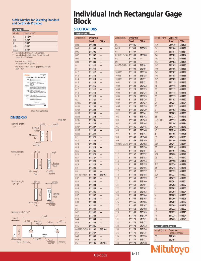
.354 -.008-.002
1.18
1 -.0
12 0
.984±.02.984±.02
x0.211 x0.211
Length
Unit: Inch
Length
Length
Airy line
2-Ø10
Nominal length 5 - 20”
Nominal length: .45 - 4”
Nominal length:.3 - 4”
Nominal length: .004 - .25”
.354 -.008-.002
.354 -.008-.002
.354 -.008-.002
1.18
1 -.0
12 0
1.37
8 -.0
12 0
1.37
8 -.0
12 0
DIMENSIONS
Example: 611310-521.1"gageblockingrade00.
We make custom length gage block length: .004-20"
US-1002
E-12
Rectangular Gage Block with CTEGage Blocks with Thermal Expansion Coefficient Data
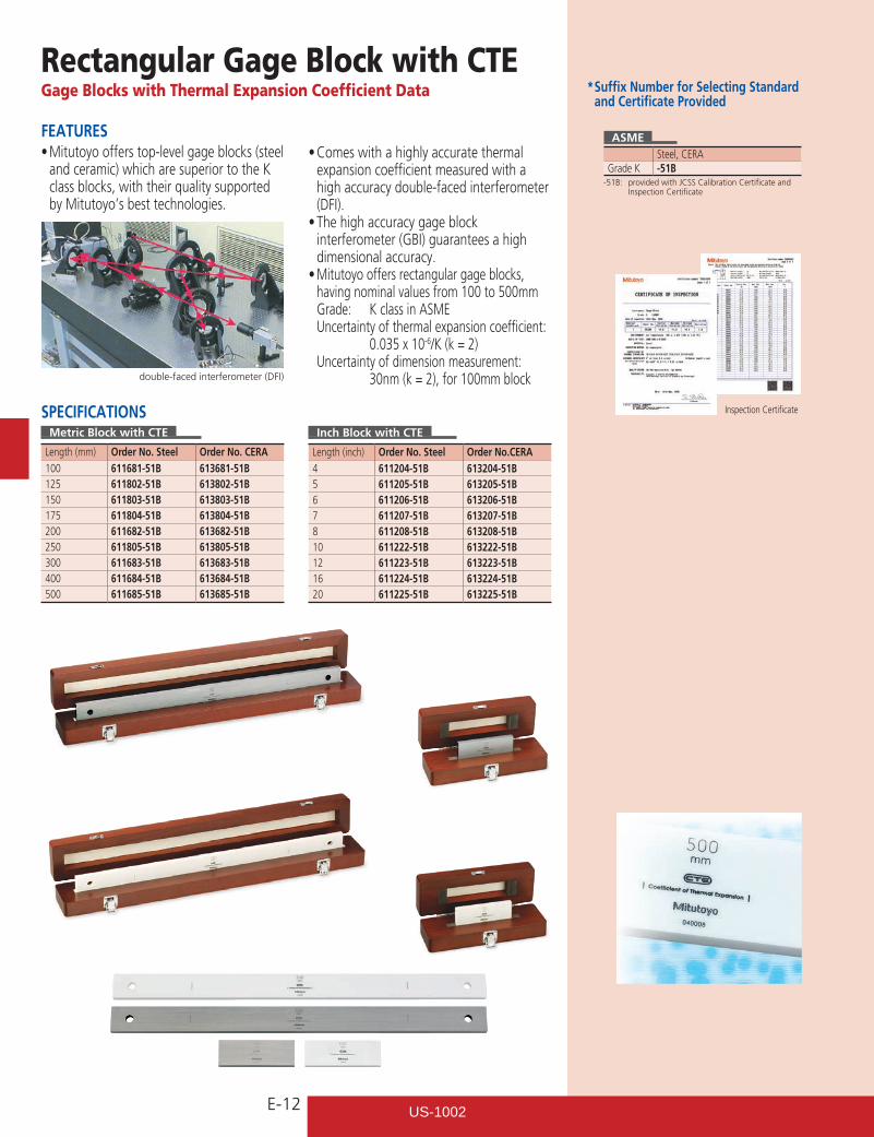
FEATURES•Mitutoyoofferstop-levelgageblocks(steel
and ceramic) which are superior to the K class blocks, with their quality supported by Mitutoyo’s best technologies.
SPECIFICATIONSMetric Block with CTE
Length (mm) Order No. Steel Order No. CERA100 611681-51B 613681-51B125 611802-51B 613802-51B150 611803-51B 613803-51B175 611804-51B 613804-51B200 611682-51B 613682-51B250 611805-51B 613805-51B300 611683-51B 613683-51B400 611684-51B 613684-51B500 611685-51B 613685-51B
* Suffix Number for Selecting Standard and Certificate Provided
Inspection Certificate
double-faced interferometer (DFI)
ASMESteel, CERA
Grade K -51B-51B: provided with JCSS Calibration Certificate and
Inspection Certificate
Inch Block with CTE
Length (inch) Order No. Steel Order No.CERA4 611204-51B 613204-51B5 611205-51B 613205-51B6 611206-51B 613206-51B7 611207-51B 613207-51B8 611208-51B 613208-51B10 611222-51B 613222-51B12 611223-51B 613223-51B16 611224-51B 613224-51B20 611225-51B 613225-51B
•Comeswithahighlyaccuratethermalexpansion coefficient measured with a high accuracy double-faced interferometer (DFI).•Thehighaccuracygageblock
interferometer (GBI) guarantees a high dimensional accuracy.•Mitutoyo offers rectangular gage blocks,
having nominal values from 100 to 500mm Grade: K class in ASME Uncertainty of thermal expansion coefficient: 0.035 x 10⁻⁶/K (k = 2) Uncertainty of dimension measurement: 30nm (k = 2), for 100mm block
US-1002
E-13
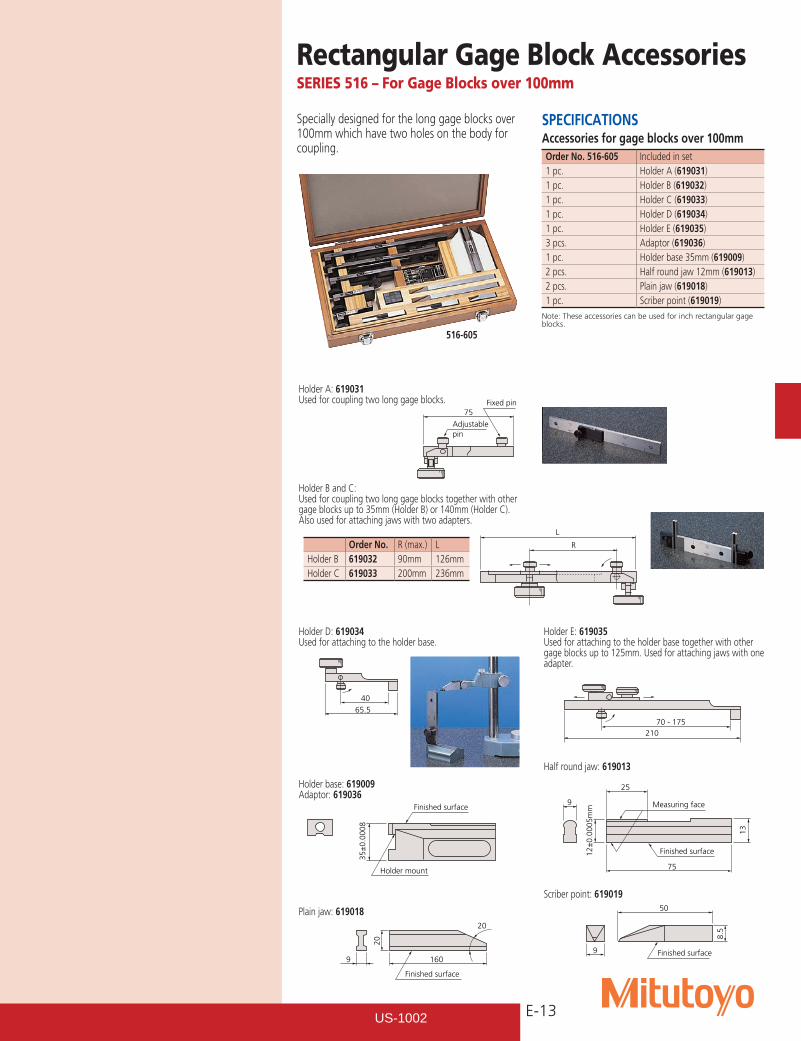
Specially designed for the long gage blocks over 100mm which have two holes on the body for coupling.
516-605
Holder B and C:Used for coupling two long gage blocks together with other gage blocks up to 35mm (Holder B) or 140mm (Holder C). Also used for attaching jaws with two adapters.
Holder base: 619009Adaptor: 619036
Half round jaw: 619013
Plain jaw: 619018
Scriber point: 619019
Holder A: 619031Used for coupling two long gage blocks.
Holder E: 619035Used for attaching to the holder base together with other gage blocks up to 125mm. Used for attaching jaws with one adapter.
Holder D: 619034Used for attaching to the holder base.
Order No. R (max.) LHolder B 619032 90mm 126mmHolder C 619033 200mm 236mm
SPECIFICATIONSAccessories for gage blocks over 100mmOrder No. 516-605 Included in set1 pc. Holder A (619031)1 pc. Holder B (619032)1 pc. Holder C (619033)1 pc. Holder D (619034)1 pc. Holder E (619035)3 pcs. Adaptor (619036)1 pc. Holder base 35mm (619009)2 pcs. Half round jaw 12mm (619013)2 pcs. Plain jaw (619018)1 pc. Scriber point (619019)
Note: These accessories can be used for inch rectangular gage blocks.
Finished surface
Holder mount
35±
0.00
08
Measuring face
Finished surface
75
25
13
12±
0.00
05m
m
9
160
20
Finished surface
9
20
Finished surface
50
9
8.5
Adjustablepin
75Fixed pin
L
R
40
65.5
21070 - 175
Rectangular Gage Block AccessoriesSERIES 516 – For Gage Blocks over 100mm
US-1002
E-14
Rectangular Gage Block AccessoriesSERIES 516
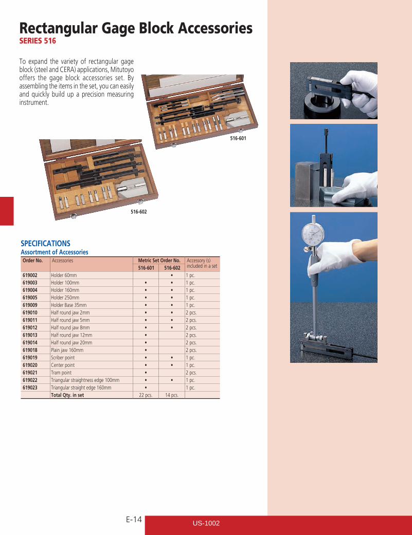
To expand the variety of rectangular gage block (steel and CERA) applications, Mitutoyo offers the gage block accessories set. By assembling the items in the set, you can easily and quickly build up a precision measuring instrument.
516-602
516-601
SPECIFICATIONS Assortment of Accessories Order No. Accessories Metric Set Order No. Accessory (s)
included in a set516-601 516-602619002 Holder 60mm • 1 pc.619003 Holder 100mm • • 1 pc.619004 Holder 160mm • • 1 pc.619005 Holder 250mm • • 1 pc.619009 Holder Base 35mm • • 1 pc.619010 Half round jaw 2mm • • 2 pcs.619011 Half round jaw 5mm • • 2 pcs.619012 Half round jaw 8mm • • 2 pcs.619013 Half round jaw 12mm • 2 pcs.619014 Half round jaw 20mm • 2 pcs.619018 Plain jaw 160mm • 2 pcs.619019 Scriber point • • 1 pc.619020 Center point • • 1 pc.619021 Tram point • 2 pcs.619022 Triangular straightness edge 100mm • • 1 pc.619023 Triangular straight edge 160mm • 1 pc.
Total Qty. in set 22 pcs. 14 pcs.
US-1002
E-15
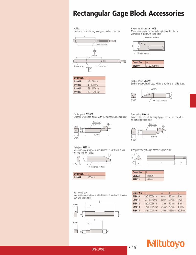
Holder:Used as a clamp if using plain jaws, scriber point, etc.
Holder base 35mm: 619009Measures a height on the surface plate and scribes a workpiece if used with the holder.
Plain jaw: 619018Measures an outside or inside diameter if used with a pair of jaws and the holder.
Scriber point: 619019Scribes a workpiece if used with the holder and holder base.
Center point: 619020Scribes a workpiece if used with the holder and holder base.
Tram point: 619021Inspects the scale of the height gage, etc., if used with the holder and holder base.
Triangular straight edge: Measures parallelism.
Finished surfaces
L
Adapter
Clamp
Finished surface Finished surface
L
Finished surface
Holder mount
A
L
20
Finished surface
9
20
Finished surface
50mm
9mm
8.5m
m
Finished surface
50mm
60
9mm
8.5
mm
Finished surface
50mm
30
9mm 8
.5m
m
L A
A
60 60
Half round jaw:Measures an outside or inside diameter if used with a pair of jaws and the holder.
Order No. H A B C619010 2±0.0005mm 6mm 40mm 8mm619011 5±0.0005mm 6mm 50mm 8mm619012 8±0.0005mm 12mm 60mm 8mm619013 12±0.0005mm 25mm 75mm 13mm619014 20±0.0005mm 25mm 125mm 20.5mm
9mm
H
A
C
B
B
C
A
H
9mm
Order No. A619009 35±0.005mm
Order No. L619018 160mm
Order No. L619022 100mm619023 160mm
Order No. L619002 15 - 61mm619003 4 - 106mm619004 62 - 165mm619005 153 - 256mm
Rectangular Gage Block Accessories
US-1002
E-16
Provided with Inspection Certificate
Metric Square Gage Block SetSERIES 516 — Metric Block Set, Long Block Set, Wear Block Set
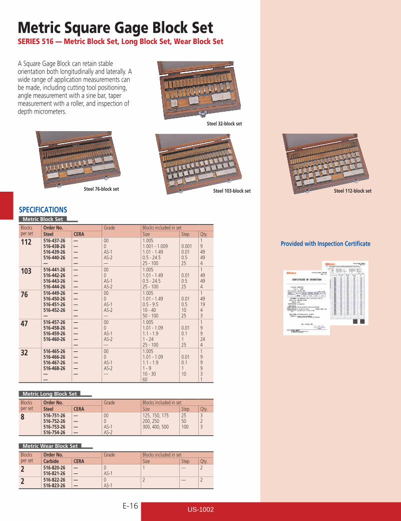
A Square Gage Block can retain stable orientation both longitudinally and laterally. A wide range of application measurements can be made, including cutting tool positioning, angle measurement with a sine bar, taper measurement with a roller, and inspection of depth micrometers.
SPECIFICATIONSMetric Block Set
Blocks per set
Order No. Grade Blocks included in setSteel CERA Size Step Qty.
112 516-437-26516-438-26516-439-26516-440-26—
—————
000AS-1AS-2—
1.0051.001 - 1.0091.01 - 1.490.5 - 24.525 - 100
0.0010.010.525
1949494
103 516-441-26516-442-26516-443-26516-444-26
————
000AS-1AS-2
1.0051.01 - 1.490.5 - 24.525 - 100
0.010.525
149494
76 516-449-26516-450-26516-451-26516-452-26—
—————
000AS-1AS-2—
1.0051.01 - 1.490.5 - 9.510 - 4050 - 100
0.010.51025
1491943
47 516-457-26516-458-26516-459-26516-460-26
—————
000AS-1AS-2—
1.0051.01 - 1.091.1 - 1.91 - 2425 - 100
0.010.1125
199244
32 516-465-26516-466-26516-467-26516-468-26——
—————
000AS-1AS-2—
1.0051.01 - 1.091.1 - 1.91 - 910 - 3060
0.010.1110
199931
Metric Long Block Set
Blocks per set
Order No. Grade Blocks included in setSteel CERA Size Step Qty.
8 516-751-26516-752-26516-753-26516-754-26
————
000AS-1AS-2
125, 150, 175200, 250300, 400, 500
2550100
323
Metric Wear Block Set
Blocks per set
Order No. Grade Blocks included in setCarbide CERA Size Step Qty.
2 516-820-26516-821-26
——
0AS-1
1 — 2
2 516-822-26516-823-26
——
0AS-1
2 — 2
Steel 112-block setSteel 103-block setSteel 76-block set
Steel 32-block set
US-1002
E-17
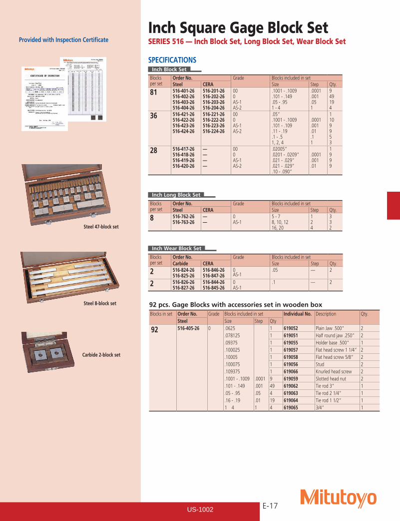
Provided with Inspection CertificateInch Square Gage Block SetSERIES 516 — Inch Block Set, Long Block Set, Wear Block Set
SPECIFICATIONSInch Block Set
Blocks per set
Order No. Grade Blocks included in setSteel CERA Size Step Qty.
81 516-401-26516-402-26516-403-26516-404-26
516-201-26516-202-26516-203-26516-204-26
000AS-1AS-2
.1001 - .1009
.101 - .149
.05 - .951 - 4
.0001
.001
.051
949194
36 516-421-26516-422-26516-423-26516-424-26
516-221-26516-222-26516-223-26516-224-26
000AS-1AS-2
.05”
.1001 - .1009
.101 - .109
.11 - .19
.1 - .51, 2, 4
.0001
.001
.01
.11
1109953
28 516-417-26516-418-26516-419-26516-420-26
————
000AS-1AS-2
.02005”
.0201 - .0209”
.021 - .029”
.021 - .029”
.10 - .090”
.0001
.001
.01
1999
Inch Long Block Set
Blocks per set
Order No. Grade Blocks included in setSteel CERA Size Step Qty.
8 516-762-26516-763-26
——
0AS-1
5 - 78, 10, 1216, 20
124
332
Inch Wear Block Set
Blocks per set
Order No. Grade Blocks included in setCarbide CERA Size Step Qty.
2 516-824-26516-825-26
516-846-26516-847-26
0AS-1
.05 — 2
2 516-826-26516-827-26
516-844-26516-845-26
0AS-1
.1 — 2
Steel 47-block set
Steel 8-block set
Carbide 2-block set
92 pcs. Gage Blocks with accessories set in wooden boxBlocks in set Order No. Grade Blocks included in set Individual No. Description Qty.
Steel Size Step Qty
92 516-405-26 0 .0625 1 619052 Plain Jaw .500” 2.078125 1 619051 Half round jaw .250” 2.09375 1 619055 Holder base .500” 1.100025 1 619057 Flat head screw 1 1/4” 2.10005 1 619058 Flat head screw 5/8” 2.100075 1 619056 Stud 2.109375 1 619066 Knurled head screw 2.1001 - .1009 .0001 9 619059 Slotted head nut 2.101 - .149 .001 49 619062 Tie rod 3” 1.05 - .95 .05 4 619063 Tie rod 2 1/4” 1.16 - .19 .01 19 619064 Tie rod 1 1/2” 11 4 1 4 619065 3/4” 1
US-1002
E-18
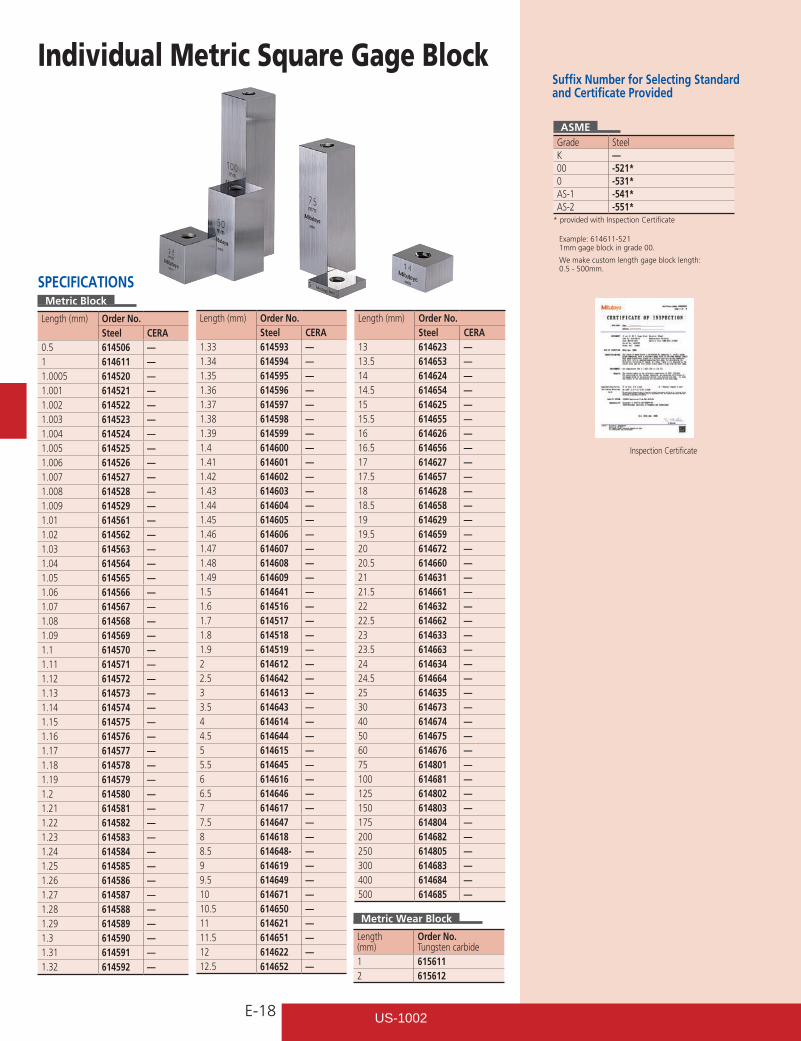
Suffix Number for Selecting Standard and Certificate Provided
ASMEGrade SteelK —00 -521*0 -531*AS-1 -541*AS-2 -551*
* provided with Inspection Certificate
Inspection Certificate
Example: 614611-5211mm gage block in grade 00.
We make custom length gage block length: 0.5 - 500mm.
Individual Metric Square Gage Block
Metric Wear Block
Length(mm)
Order No.Tungsten carbide
1 6156112 615612
SPECIFICATIONSMetric Block
Length (mm) Order No.Steel CERA
0.5 614506 —1 614611 —1.0005 614520 —1.001 614521 —1.002 614522 —1.003 614523 —1.004 614524 —1.005 614525 —1.006 614526 —1.007 614527 —1.008 614528 —1.009 614529 —1.01 614561 —1.02 614562 —1.03 614563 —1.04 614564 —1.05 614565 —1.06 614566 —1.07 614567 —1.08 614568 —1.09 614569 —1.1 614570 —1.11 614571 —1.12 614572 —1.13 614573 —1.14 614574 —1.15 614575 —1.16 614576 —1.17 614577 —1.18 614578 —1.19 614579 —1.2 614580 —1.21 614581 —1.22 614582 —1.23 614583 —1.24 614584 —1.25 614585 —1.26 614586 —1.27 614587 —1.28 614588 —1.29 614589 —1.3 614590 —1.31 614591 —1.32 614592 —
Length (mm) Order No.Steel CERA
1.33 614593 —1.34 614594 —1.35 614595 —1.36 614596 —1.37 614597 —1.38 614598 —1.39 614599 —1.4 614600 —1.41 614601 —1.42 614602 —1.43 614603 —1.44 614604 —1.45 614605 —1.46 614606 —1.47 614607 —1.48 614608 —1.49 614609 —1.5 614641 —1.6 614516 —1.7 614517 —1.8 614518 —1.9 614519 —2 614612 —2.5 614642 —3 614613 —3.5 614643 —4 614614 —4.5 614644 —5 614615 —5.5 614645 —6 614616 —6.5 614646 —7 614617 —7.5 614647 —8 614618 —8.5 614648- —9 614619 —9.5 614649 —10 614671 —10.5 614650 —11 614621 —11.5 614651 —12 614622 —12.5 614652 —
Length (mm) Order No.Steel CERA
13 614623 —13.5 614653 —14 614624 —14.5 614654 —15 614625 —15.5 614655 —16 614626 —16.5 614656 —17 614627 —17.5 614657 —18 614628 —18.5 614658 —19 614629 —19.5 614659 —20 614672 —20.5 614660 —21 614631 —21.5 614661 —22 614632 —22.5 614662 —23 614633 —23.5 614663 —24 614634 —24.5 614664 —25 614635 —30 614673 —40 614674 —50 614675 —60 614676 —75 614801 —100 614681 —125 614802 —150 614803 —175 614804 —200 614682 —250 614805 —300 614683 —400 614684 —500 614685 —
US-1002
E-19
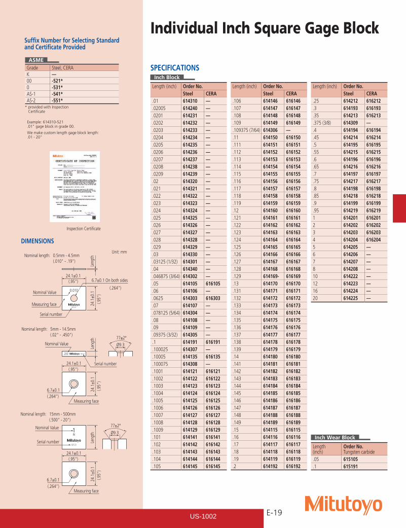
Inspection Certificate
Example: 614310-521.01"gageblockingrade00.
We make custom length gage block length: .01-20"
Individual Inch Square Gage Block
SPECIFICATIONSInch Block
Length (inch) Order No.Steel CERA
.01 614310 —
.02005 614240 —
.0201 614231 —
.0202 614232 —
.0203 614233 —
.0204 614234 —
.0205 614235 —
.0206 614236 —
.0207 614237 —
.0208 614238 —
.0209 614239 —
.02 614320 —
.021 614321 —
.022 614322 —
.023 614323 —
.024 614324 —
.025 614325 —
.026 614326 —
.027 614327 —
.028 614328 —
.029 614329 —
.03 614330 —
.03125 (1/32) 614301 —
.04 614340 —
.046875 (3/64) 614302 —
.05 614105 616105
.06 614106 —
.0625 614303 616303
.07 614107 —
.078125 (5/64) 614304 —
.08 614108 —
.09 614109 —
.09375 (3/32) 614305 —
.1 614191 616191
.100025 614307 —
.10005 614135 616135
.100075 614308 —
.1001 614121 616121
.1002 614122 616122
.1003 614123 616123
.1004 614124 616124
.1005 614125 616125
.1006 614126 616126
.1007 614127 616127
.1008 614128 616128
.1009 614129 616129
.101 614141 616141
.102 614142 616142
.103 614143 616143
.104 614144 616144
.105 614145 616145
Length (inch) Order No.Steel CERA
.106 614146 616146
.107 614147 616147
.108 614148 616148
.109 614149 616149
.109375 (7/64) 614306 —
.11 614150 616150
.111 614151 616151
.112 614152 616152
.113 614153 616153
.114 614154 616154
.115 614155 616155
.116 614156 616156
.117 614157 616157
.118 614158 616158
.119 614159 616159
.12 614160 616160
.121 614161 616161
.122 614162 616162
.123 614163 616163
.124 614164 616164
.125 614165 616165
.126 614166 616166
.127 614167 616167
.128 614168 616168
.129 614169- 616169
.13 614170 616170
.131 614171 616171
.132 614172 616172
.133 614173 616173
.134 614174 616174
.135 614175 616175
.136 614176 616176
.137 614177 616177
.138 614178 616178
.139 614179 616179
.14 614180 616180
.141 614181 616181
.142 614182 616182
.143 614183 616183
.144 614184 616184
.145 614185 616185
.146 614186 616186
.147 614187 616187
.148 614188 616188
.149 614189 616189
.15 614115 616115
.16 614116 616116
.17 614117 616117
.18 614118 616118
.19 614119 616119
.2 614192 616192
Length (inch) Order No.Steel CERA
.25 614212 616212
.3 614193 616193
.35 614213 616213
.375 (3/8) 614309 —
.4 614194 616194
.45 614214 616214
.5 614195 616195
.55 614215 616215
.6 614196 616196
.65 614216 616216
.7 614197 616197
.75 614217 616217
.8 614198 616198
.85 614218 616218
.9 614199 616199
.95 614219 6162191 614201 6162012 614202 6162023 614203 6162034 614204 6162045 614205 —6 614206 —7 614207 —8 614208 —10 614222 —12 614223 —16 614224 —20 614225 —
Inch Wear Block
Length(inch)
Order No.Tungsten carbide
.05 615105
.1 615191
Suffix Number for Selecting Standard and Certificate Provided
ASMEGrade Steel, CERAK —00 -521*0 -531*AS-1 -541*AS-2 -551*
* provided with Inspection Certificate
DIMENSIONS
IN
0.010
.200
1
92123
92123
92123
24.1±0.1 (.95”)
(.95”)
(.95”)
(.264”)
(.264”)
(.264”)
24.1±0.1
77±2°
Ø9.3
24.1
±0.1
(.9
5”)
(.95”
)(.9
5”)
Leng
th
Measuring face
24.1±0.1
77±2°
Ø9.3
24.1
±0.1
Le
ngth
Le
ngth
Nominal length: 5mm - 14.5mm (.02" - .450")
Nominal length: 15mm - 500mm (.500" - 20")
Nominal length: 0.5mm - 4.5mm (.010" - .19")
Serial number
Serial number
Serial number
6.7±0.1
Measuring face
24.1
±0.1
6.7±0.1
Nominal Value
Unit: mm
Measuring face
Nominal Value
Nominal Value
6.7±0.1 On both sides
US-1002
E-20
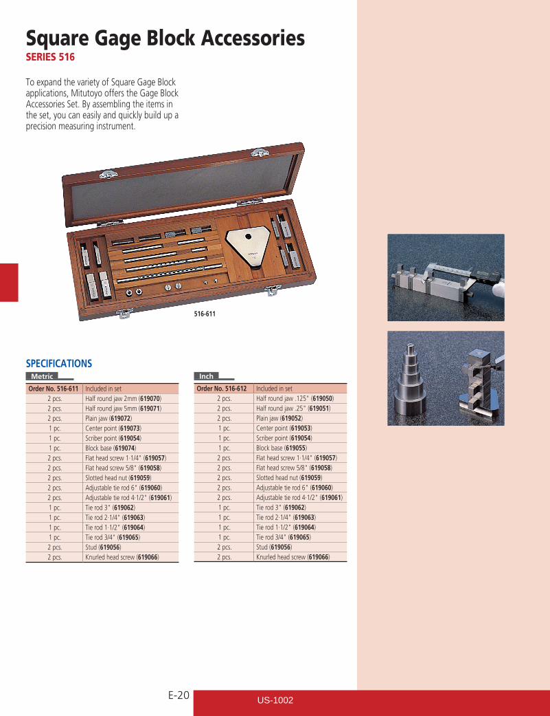
Square Gage Block AccessoriesSERIES 516
To expand the variety of Square Gage Block applications, Mitutoyo offers the Gage Block Accessories Set. By assembling the items in the set, you can easily and quickly build up a precision measuring instrument.
516-611
Inch
Order No. 516-612 Included in set2 pcs. Halfroundjaw.125"(619050)2 pcs. Halfroundjaw.25"(619051)2 pcs. Plain jaw (619052)1 pc. Center point (619053)1 pc. Scriber point (619054)1 pc. Block base (619055)2 pcs. Flatheadscrew1·1/4"(619057)2 pcs. Flatheadscrew5/8"(619058)2 pcs. Slotted head nut (619059)2 pcs. Adjustabletierod6"(619060)2 pcs. Adjustabletierod4·1/2"(619061)1 pc. Tierod3"(619062)1 pc. Tierod2·1/4"(619063)1 pc. Tierod1·1/2"(619064)1 pc. Tierod3/4"(619065)2 pcs. Stud (619056)2 pcs. Knurled head screw (619066)
SPECIFICATIONSMetric
Order No. 516-611 Included in set2 pcs. Half round jaw 2mm (619070)2 pcs. Half round jaw 5mm (619071)2 pcs. Plain jaw (619072)1 pc. Center point (619073)1 pc. Scriber point (619054)1 pc. Block base (619074)2 pcs. Flatheadscrew1·1/4"(619057)2 pcs. Flatheadscrew5/8"(619058)2 pcs. Slotted head nut (619059)2 pcs. Adjustabletierod6"(619060)2 pcs. Adjustabletierod4·1/2"(619061)1 pc. Tierod3"(619062)1 pc. Tierod2·1/4"(619063)1 pc. Tierod1·1/2"(619064)1 pc. Tierod3/4"(619065)2 pcs. Stud (619056)2 pcs. Knurled head screw (619066)
US-1002
E-21
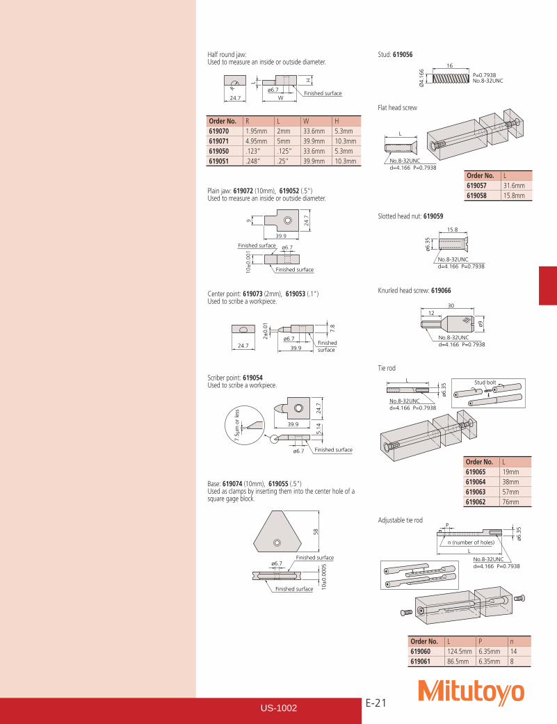
Half round jaw:Used to measure an inside or outside diameter.
Plain jaw: 619072 (10mm), 619052(.5")Used to measure an inside or outside diameter.
Center point: 619073 (2mm), 619053(.1")Used to scribe a workpiece.
Scriber point: 619054Used to scribe a workpiece.
Base: 619074 (10mm), 619055(.5")Used as clamps by inserting them into the center hole of a square gage block.
Order No. R L W H619070 1.95mm 2mm 33.6mm 5.3mm619071 4.95mm 5mm 39.9mm 10.3mm619050 .123” .125” 33.6mm 5.3mm619051 .248” .25” 39.9mm 10.3mm
Stud: 619056
Flat head screw
Order No. L619057 31.6mm619058 15.8mm
Order No. L619065 19mm619064 38mm619063 57mm619062 76mm
Slotted head nut: 619059
Knurled head screw: 619066
Tie rod
Adjustable tie rod
Order No. L P n619060 124.5mm 6.35mm 14619061 86.5mm 6.35mm 8
R
24.7 W
L H
ø6.7Finished surface
39.9
ø6.7Finished surface
Finished surface
910
±0.
001
24.7
2±0.
01
7.8
Finished surface
24.7 39.9
ø6.7
39.9
24.7
5.14
7.5µ
m o
r le
ss
ø6.7 Finished surface
58
10±
0.00
05
Finished surfaceø6.7
Finished surface
16
Ø4.166
P=0.7938No.8-32UNC
No.8-32UNC d=4.166 P=0.7938
L
15.8
No.8-32UNC d=4.166 P=0.7938
ø6.3
5
No.8-32UNC d=4.166 P=0.7938
3012
ø9
No.8-32UNCd=4.166 P=0.7938
ø6.3
5 Stud boltL
Pø6
.35
n (number of holes)
No.8-32UNCd=4.166 P=0.7938
L
US-1002
E-22
CERASTON(Arkansas stone)
Rubber
CERASTON(Arkansas stone)
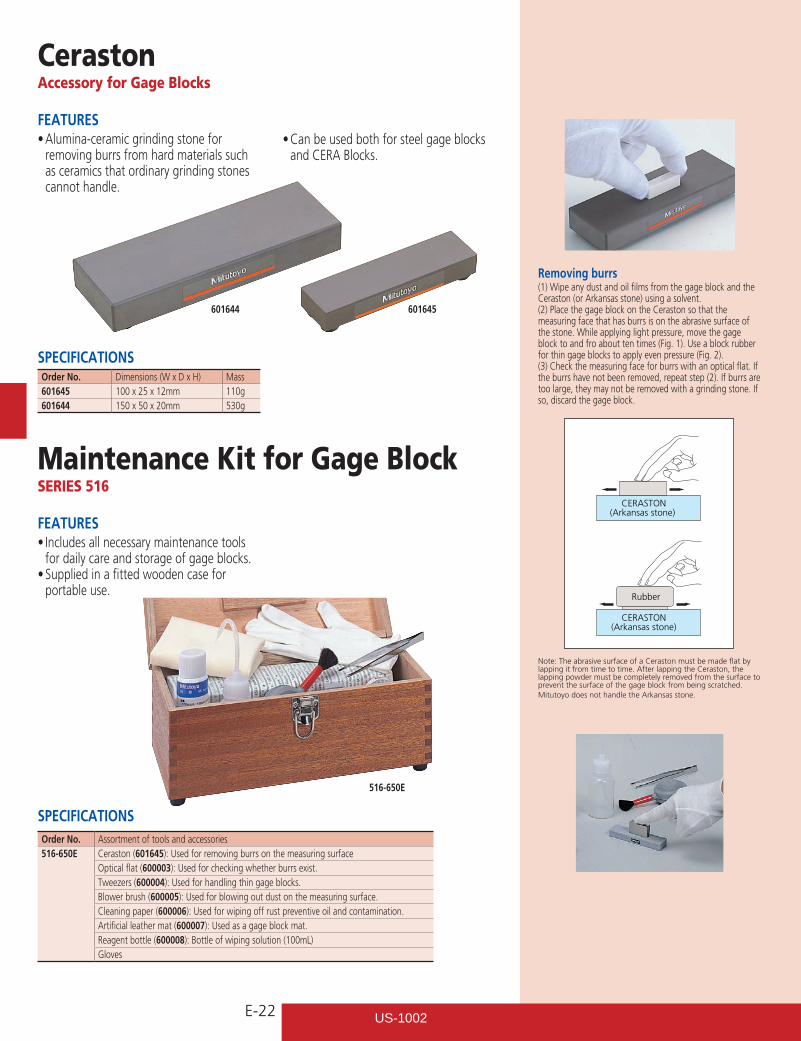
CerastonAccessory for Gage Blocks
Maintenance Kit for Gage BlockSERIES 516
FEATURES•Alumina-ceramicgrindingstonefor
removing burrs from hard materials such as ceramics that ordinary grinding stones cannot handle.
SPECIFICATIONSOrder No. Dimensions (W x D x H) Mass601645 100 x 25 x 12mm 110g601644 150 x 50 x 20mm 530g
FEATURES•Includesallnecessarymaintenancetools
for daily care and storage of gage blocks.•Suppliedinafittedwoodencasefor
portable use.
SPECIFICATIONSOrder No. Assortment of tools and accessories516-650E Ceraston (601645): Used for removing burrs on the measuring surface
Optical flat (600003): Used for checking whether burrs exist.Tweezers (600004): Used for handling thin gage blocks.Blower brush (600005): Used for blowing out dust on the measuring surface.Cleaning paper (600006): Used for wiping off rust preventive oil and contamination.Artificial leather mat (600007): Used as a gage block mat.Reagent bottle (600008): Bottle of wiping solution (100mL)Gloves
Removing burrs(1) Wipe any dust and oil films from the gage block and the Ceraston (or Arkansas stone) using a solvent.(2) Place the gage block on the Ceraston so that the measuring face that has burrs is on the abrasive surface of the stone. While applying light pressure, move the gage block to and fro about ten times (Fig. 1). Use a block rubber for thin gage blocks to apply even pressure (Fig. 2).(3) Check the measuring face for burrs with an optical flat. If the burrs have not been removed, repeat step (2). If burrs are too large, they may not be removed with a grinding stone. If so, discard the gage block.
Note: The abrasive surface of a Ceraston must be made flat by lapping it from time to time. After lapping the Ceraston, the lapping powder must be completely removed from the surface to prevent the surface of the gage block from being scratched.Mitutoyo does not handle the Arkansas stone.
•Canbeusedbothforsteelgageblocksand CERA Blocks.
516-650E
601644 601645
US-1002
E-23
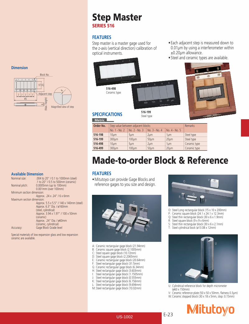
Step MasterSERIES 516
Made-to-order Block & ReferenceFEATURES•MitutoyocanprovideGageBlocksand
reference gages to you size and design.
Adjacent step
Magnified view of step
Block No.
45
15 25
R
7
300
1 2 3 4 5
100 50 20 µm
7 7 7 7
6(M
ax. h
eigh
t)
Dimension
FEATURESStep master is a master gage used for the z-axis (vertical direction) calibration of optical instruments.
•Eachadjacentstepismeasureddownto0.01µm by using a interferometer within
±0.20µm allowance.•Steelandceramictypesareavailable.
516-498Ceramic type
516-199Steel typeSPECIFICATIONS
Metric
Order No. Step value between adjacent blocks RemarksNo. 1 - No. 2 No. 2 - No. 3 No. 3 - No. 4 No. 4 - No. 5
516-198 10µm 5µm 2µm 1µm Steel type516-199 300µm 100µm 50µm 20µm Steel type516-498 10µm 5µm 2µm 1µm Ceramic type516-499 300µm 100µm 50µm 20µm Ceramic type
Available DimensionNominal size: .004 to 20” / 0.1 to 1000mm (steel) .1 to 20” / 0.5 to 500mm (ceramic)Nominal pitch: 0.0005mm (up to 100mm) 0.001mm (over 100mm)Minimum section dimension: Approx. .24 x .24” / 6 x 6mmMaximum section dimension: Approx. 5.5 x 5.5” / 140 x 140mm (steel) Approx. 6.3” Dia. / ø160mm (steel, cylindrical) Approx. 3.94 x 1.97” / 100 x 50mm (ceramic) Approx. .24” Dia. / ø60mm (ceramic, cylindrical)Accuracy: Gage Block Grade level
Special materials of low expansion glass and low expansion ceramic are available.
U: Cylindrical reference block for depth micrometer (ø60 x 150mm)
V: Ceramic reference plate (50 x 50 x 50mm, flatness 0.3µm)W: Ceramic stepped block (30 x 18 x 5mm, step: 0.15mm)
O: Steel Long rectangular block (15 x 10 x 200mm)P: Ceramic square block (24.1 x 24.1 x 12.3mm)Q: Steel thin rectangular block (30 x 6 x 1.9mm)R: Steel square block (9 x 9 x 6mm)S: Steel thin rectangular block (30 x 6 x 2.1mm)T: Steel cylindrical bock (ø13.08 x 12mm)
E
A: Ceramic rectangular gage block (21.94mm)B: Ceramic square gage block (2.1005mm)C: Steel square gage block (10.72mm)D: Steel square gage block (2.2065mm)E: Ceramic rectangular gage block (20.64mm)F: Steel rectangular gage block (31.5mm)G: Ceramic rectangular gage block (6.34mm)H: Steel rectangular gage block (3.603mm)I: Steel rectangular gage block (1.1505mm)J: Steel rectangular gage block (0.555mm)K: Steel rectangular gage block (6.156mm)L: Steel rectangular gage block (9.694mm)M: Steel rectangular gage block (10.02mm)
A F
B CD
G
H I J
KLM
VW
U
TS
R
O
Q
P
US-1002
E-24
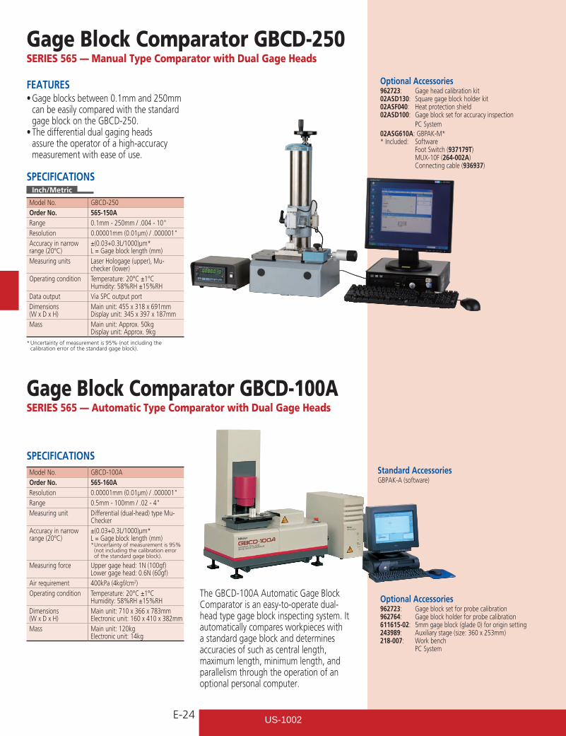
Gage Block Comparator GBCD-100ASERIES 565 — Automatic Type Comparator with Dual Gage Heads
The GBCD-100A Automatic Gage Block Comparator is an easy-to-operate dual-head type gage block inspecting system. It automatically compares workpieces with a standard gage block and determines accuracies of such as central length, maximum length, minimum length, and parallelism through the operation of an optional personal computer.
Optional Accessories962723: Gage block set for probe calibration962764: Gage block holder for probe calibration611615-02: 5mm gage block (glade 0) for origin setting243989: Auxiliary stage (size: 360 x 253mm)218-007: Work bench PC System
SPECIFICATIONSModel No. GBCD-100AOrder No. 565-160AResolution 0.00001mm(0.01µm)/.000001"Range 0.5mm-100mm/.02-4"Measuring unit Differential (dual-head) type Mu-
CheckerAccuracy in narrowrange (20°C)
±(0.03+0.3L/1000)µm* L = Gage block length (mm)* Uncertainty of measurement is 95% (not including the calibration error of the standard gage block).
Measuring force Upper gage head: 1N (100gf)Lower gage head: 0.6N (60gf)
Air requirement 400kPa (4kgf/cm2)Operating condition Temperature: 20°C ±1°C
Humidity: 58%RH ±15%RHDimensions(W x D x H)
Main unit: 710 x 366 x 783mmElectronic unit: 160 x 410 x 382mm
Mass Main unit: 120kgElectronic unit: 14kg
Gage Block Comparator GBCD-250SERIES 565 — Manual Type Comparator with Dual Gage Heads
FEATURES•Gageblocksbetween0.1mmand250mm
can be easily compared with the standard gage block on the GBCD-250.•Thedifferentialdualgagingheads
assure the operator of a high-accuracy measurement with ease of use.
SPECIFICATIONSInch/Metric
Model No. GBCD-250Order No. 565-150ARange 0.1mm-250mm/.004-10"Resolution 0.00001mm(0.01µm)/.000001"Accuracy in narrowrange (20°C)
±(0.03+0.3L/1000)µm* L = Gage block length (mm)
Measuring units Laser Hologage (upper), Mu-checker (lower)
Operating condition Temperature: 20°C ±1°C Humidity: 58%RH ±15%RH
Data output Via SPC output portDimensions (W x D x H)
Main unit: 455 x 318 x 691mm Display unit: 345 x 397 x 187mm
Mass Main unit: Approx. 50kg Display unit: Approx. 9kg
* Uncertainty of measurement is 95% (not including the calibration error of the standard gage block).
Optional Accessories962723: Gage head calibration kit02ASD130: Square gage block holder kit02ASF040: Heat protection shield02ASD100: Gage block set for accuracy inspection PC System02ASG610A: GBPAK-M** Included: Software Foot Switch (937179T) MUX-10F (264-002A) Connecting cable (936937)
Standard AccessoriesGBPAK-A (software)
US-1002
E-25
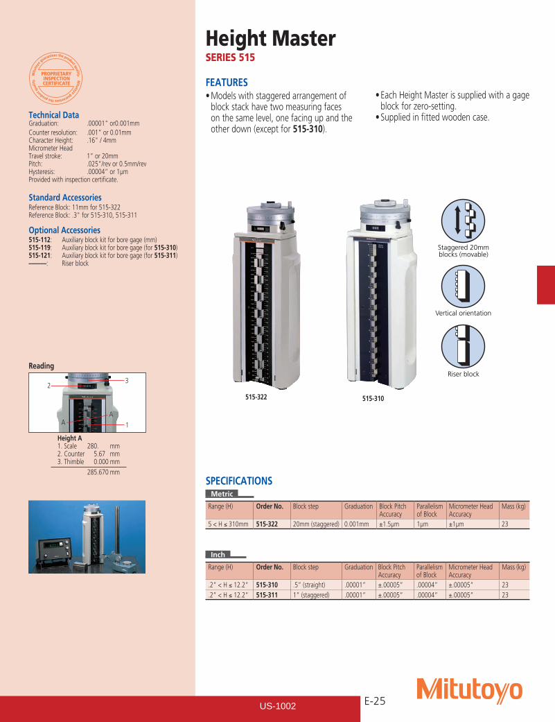
Height MasterSERIES 515
Technical Data Graduation: .00001"or0.001mmCounter resolution: .001” or 0.01mmCharacterHeight: .16"/4mmMicrometer HeadTravel stroke: 1” or 20mmPitch: .025”/rev or 0.5mm/revHysteresis: .00004” or 1µmProvided with inspection certificate.
Standard AccessoriesReference Block: 11mm for 515-322ReferenceBlock:.3"for515-310,515-311
Optional Accessories515-112: Auxiliary block kit for bore gage (mm)515-119: Auxiliary block kit for bore gage (for 515-310)515-121: Auxiliary block kit for bore gage (for 515-311)––––––: Riser block
FEATURES•Modelswithstaggeredarrangementof
block stack have two measuring faces on the same level, one facing up and the other down (except for 515-310).
•EachHeightMasterissuppliedwithagageblock for zero-setting.•Suppliedinfittedwoodencase.
Staggered 20mmblocks (movable)
Vertical orientation
Riser block
515-310
Inch
Range (H) Order No. Block step Graduation Block Pitch Accuracy
Parallelism of Block
Micrometer Head Accuracy
Mass (kg)
.2” < H ≤ 12.2” 515-310 .5” (straight) .00001” ±.00005” .00004” ±.00005” 23
.2” < H ≤ 12.2” 515-311 1” (staggered) .00001” ±.00005” .00004” ±.00005” 23
SPECIFICATIONSMetric
Range (H) Order No. Block step Graduation Block Pitch Accuracy
Parallelism of Block
Micrometer Head Accuracy
Mass (kg)
5 < H ≤ 310mm 515-322 20mm (staggered) 0.001mm ±1.5µm 1µm ±1µm 23
Height A1. Scale 280. mm2. Counter 5.67 mm3. Thimble 0.000 mm
285.670 mm
Reading
515-322
1
23
AA
US-1002
E-26
Staggered 20mmblocks (movable)
Vertical orientation
Riser block
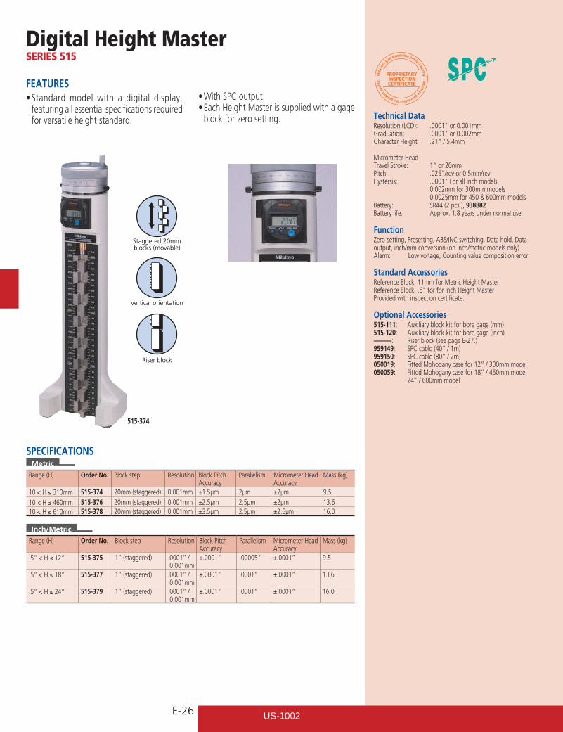
Digital Height MasterSERIES 515
FEATURES•Standardmodel with a digital display,
featuring all essential specifications required for versatile height standard.
•WithSPCoutput.•EachHeightMasterissuppliedwithagage
block for zero setting.
515-374
Inch/Metric
Range (H) Order No. Block step Resolution Block Pitch Accuracy
Parallelism Micrometer Head Accuracy
Mass (kg)
.5” < H ≤ 12” 515-375 1” (staggered) .0001” / 0.001mm
±.0001” .00005” ±.0001” 9.5
.5” < H ≤ 18” 515-377 1” (staggered) .0001” / 0.001mm
±.0001” .0001” ±.0001” 13.6
.5” < H ≤ 24” 515-379 1” (staggered) .0001” / 0.001mm
±.0001” .0001” ±.0001” 16.0
SPECIFICATIONSMetric
Range (H) Order No. Block step Resolution Block Pitch Accuracy
Parallelism Micrometer Head Accuracy
Mass (kg)
10 < H ≤ 310mm 515-374 20mm (staggered) 0.001mm ±1.5µm 2µm ±2µm 9.510 < H ≤ 460mm 515-376 20mm (staggered) 0.001mm ±2.5µm 2.5µm ±2µm 13.610 < H ≤ 610mm 515-378 20mm (staggered) 0.001mm ±3.5µm 2.5µm ±2.5µm 16.0
Technical DataResolution(LCD): .0001"or0.001mmGraduation: .0001"or0.002mmCharacterHeight .21"/5.4mm
Micrometer HeadTravelStroke: 1"or20mmPitch: .025"/revor0.5mm/revHystersis: .0001"Forallinchmodels 0.002mm for 300mm models 0.0025mm for 450 & 600mm modelsBattery: SR44 (2 pcs.), 938882Battery life: Approx. 1.8 years under normal use
FunctionZero-setting, Presetting, ABS/INC switching, Data hold, Data output, inch/mm conversion (on inch/metric models only)Alarm: Low voltage, Counting value composition error
Standard AccessoriesReference Block: 11mm for Metric Height MasterReferenceBlock:.6"forforInchHeightMasterProvided with inspection certificate.
Optional Accessories515-111: Auxiliary block kit for bore gage (mm)515-120: Auxiliary block kit for bore gage (inch)––––––: Riser block (see page E-27.)959149: SPC cable (40” / 1m)959150: SPC cable (80” / 2m)050019: Fitted Mohogany case for 12” / 300mm model050059: Fitted Mohogany case for 18” / 450mm model 24"/600mmmodel
US-1002
E-27
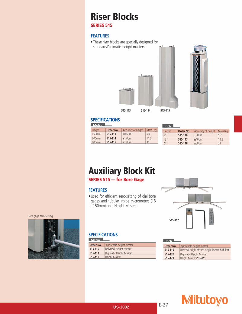
Riser BlocksSERIES 515
FEATURES•Theseriserblocksarespeciallydesignedfor
standard/Digimatic height masters.
SPECIFICATIONSMetric
Height Order No. Accuracy of height Mass (kg)150mm 515-113 ±0.6µm 5.7300mm 515-114 ±1.0µm 11.3600mm 515-115 ±2.0µm 31
Inch
Height Order No. Accuracy of height Mass (kg)6” 515-116 ±20µin 5.712” 515-117 ±40µin 11.324” 515-118 ±80µin 31
Auxiliary Block KitSERIES 515 — for Bore Gage
FEATURES•Usedforefficientzero-settingofdialbore
gages and tubular inside micrometers (18 - 150mm) on a Height Master.
SPECIFICATIONSMetric
Order No. Applicable height master515-110 Universal Height Master515-111 Digimatic Height Master515-112 Height Master
Inch
Order No. Applicable height master515-119 Universal Height Master, Height Master (515-310)515-120 Digimatic Height Master515-121 Height Master (515-311)
515-113 515-114 515-115
515-112Bore gage zero-setting
US-1002
E-28
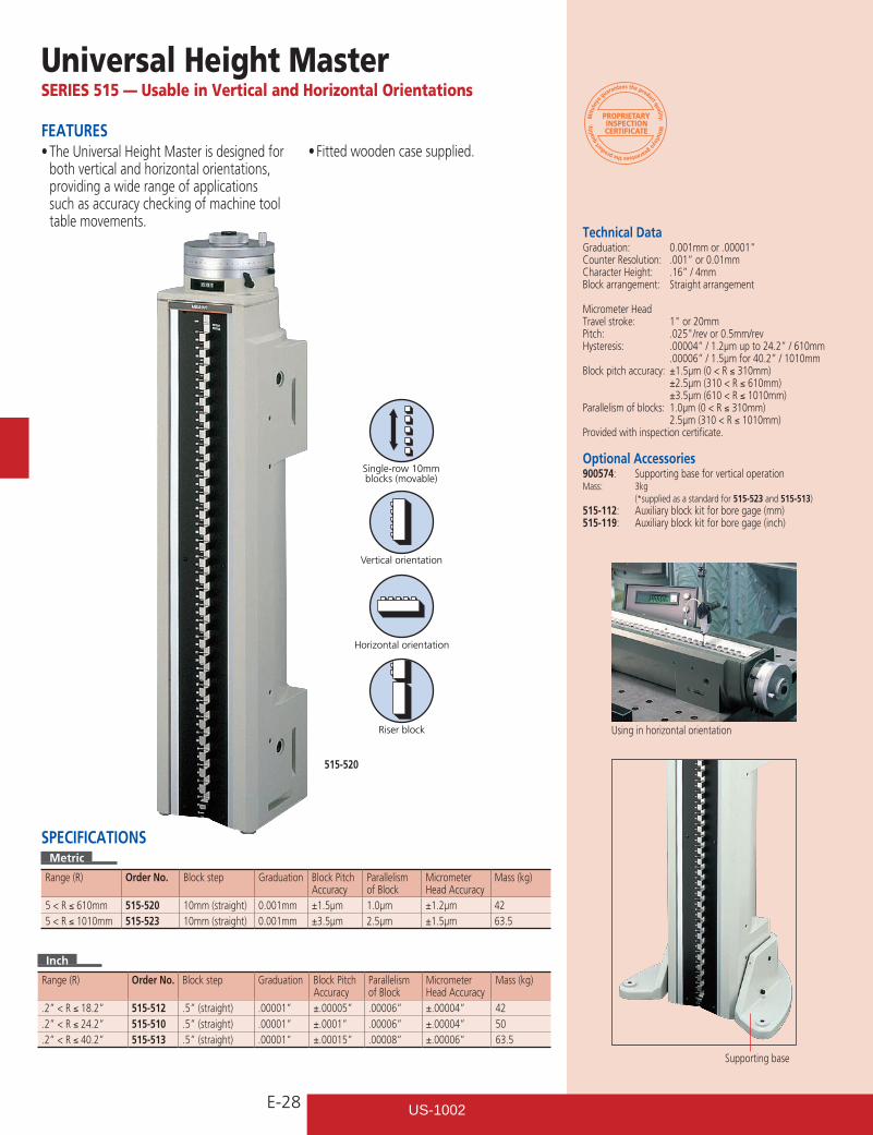
Single-row 10mmblocks (movable)
Vertical orientation
Horizontal orientation
Riser block
Universal Height MasterSERIES 515 — Usable in Vertical and Horizontal Orientations
Technical DataGraduation: 0.001mmor.00001"Counter Resolution: .001” or 0.01mmCharacter Height: .16” / 4mmBlock arrangement: Straight arrangement
Micrometer HeadTravel stroke: 1"or20mmPitch: .025"/revor0.5mm/revHysteresis: .00004” / 1.2µm up to 24.2” / 610mm .00006” / 1.5µm for 40.2” / 1010mmBlock pitch accuracy: ±1.5µm (0 < R ≤ 310mm) ±2.5µm (310 < R ≤ 610mm) ±3.5µm (610 < R ≤ 1010mm)Parallelism of blocks: 1.0µm (0 < R ≤ 310mm) 2.5µm (310 < R ≤ 1010mm)Provided with inspection certificate.
Optional Accessories900574: Supporting base for vertical operation Mass: 3kg (*supplied as a standard for 515-523 and 515-513)515-112: Auxiliary block kit for bore gage (mm)515-119: Auxiliary block kit for bore gage (inch)
FEATURES•TheUniversalHeightMasterisdesignedfor
both vertical and horizontal orientations, providing a wide range of applications such as accuracy checking of machine tool table movements.
•Fittedwoodencasesupplied.
515-520
Inch
Range (R) Order No. Block step Graduation Block Pitch Accuracy
Parallelism of Block
Micrometer Head Accuracy
Mass (kg)
.2” < R ≤ 18.2” 515-512 .5” (straight) .00001” ±.00005” .00006” ±.00004” 42
.2” < R ≤ 24.2” 515-510 .5” (straight) .00001” ±.0001” .00006” ±.00004” 50
.2” < R ≤ 40.2” 515-513 .5” (straight) .00001” ±.00015” .00008” ±.00006” 63.5
SPECIFICATIONSMetric
Range (R) Order No. Block step Graduation Block Pitch Accuracy
Parallelism of Block
Micrometer Head Accuracy
Mass (kg)
5 < R ≤ 610mm 515-520 10mm (straight) 0.001mm ±1.5µm 1.0µm ±1.2µm 425 < R ≤ 1010mm 515-523 10mm (straight) 0.001mm ±3.5µm 2.5µm ±1.5µm 63.5
Using in horizontal orientation
Supporting base
US-1002
E-29
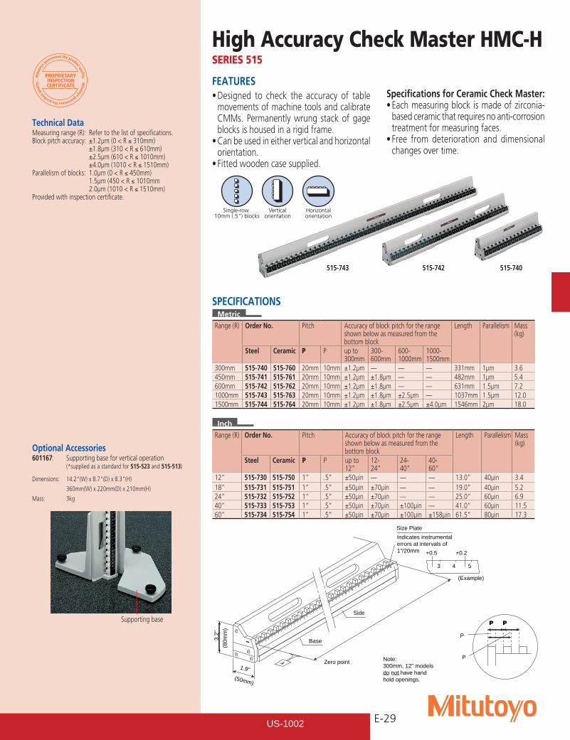
Single-row 10mm (.5") blocks
Verticalorientation
Horizontalorientation
FEATURES•Designed to check the accuracy of table
movements of machine tools and calibrate CMMs. Permanently wrung stack of gage blocks is housed in a rigid frame.•Canbeusedineitherverticalandhorizontal
orientation.•Fittedwoodencasesupplied.
Specifications for Ceramic Check Master: •Eachmeasuringblockismadeofzirconia-
based ceramic that requires no anti-corrosion treatment for measuring faces.•Free from deterioration and dimensional
changes over time.
High Accuracy Check Master HMC-HSERIES 515
Technical DataMeasuring range (R): Refer to the list of specifications. Block pitch accuracy: ±1.2µm (0 < R ≤ 310mm) ±1.8µm (310 < R ≤ 610mm) ±2.5µm (610 < R ≤ 1010mm) ±4.0µm (1010 < R ≤ 1510mm)Parallelism of blocks: 1.0µm (0 < R ≤ 450mm) 1.5µm (450 < R ≤ 1010mm 2.0µm (1010 < R ≤ 1510mm)Provided with inspection certificate.
Inch
Range (R) Order No. Pitch Accuracy of block pitch for the range shown below as measured from the bottom block
Length Parallelism Mass (kg)
Steel Ceramic P P up to 12”
12- 24”
24- 40”
40- 60”
12” 515-730 515-750 1” .5” ±50µin — — — 13.0” 40µin 3.418” 515-731 515-751 1” .5” ±50µin ±70µin — — 19.0” 40µin 5.224” 515-732 515-752 1” .5” ±50µin ±70µin — — 25.0” 60µin 6.940” 515-733 515-753 1” .5” ±50µin ±70µin ±100µin — 41.0” 60µin 11.560” 515-734 515-754 1” .5” ±50µin ±70µin ±100µin ±158µin 61.5” 80µin 17.3
SPECIFICATIONSMetric
Range (R) Order No. Pitch Accuracy of block pitch for the range shown below as measured from the bottom block
Length Parallelism Mass (kg)
Steel Ceramic P P up to 300mm
300- 600mm
600- 1000mm
1000- 1500mm
300mm 515-740 515-760 20mm 10mm ±1.2µm — — — 331mm 1µm 3.6450mm 515-741 515-761 20mm 10mm ±1.2µm ±1.8µm — — 482mm 1µm 5.4600mm 515-742 515-762 20mm 10mm ±1.2µm ±1.8µm — — 631mm 1.5µm 7.21000mm 515-743 515-763 20mm 10mm ±1.2µm ±1.8µm ±2.5µm — 1037mm 1.5µm 12.01500mm 515-744 515-764 20mm 10mm ±1.2µm ±1.8µm ±2.5µm ±4.0µm 1546mm 2µm 18.0
Supporting base
515-743 515-742 515-740
Optional Accessories601167: Supporting base for vertical operation (*supplied as a standard for 515-523 and 515-513)
Dimensions: 14.2"(W)x8.7"(D)x8.3"(H)
360mm(W) x 220mm(D) x 210mm(H)
Mass: 3kg
1.9"
(50mm)
3.2"
(80m
m)
+0.5 +0.2
3 4 5
(Example)
Base
Side
Zero point
Size Plate
Indicates instrumentalerrors at intervals of1"/20mm
Note:300mm, 12" modelsdo not have handhold openings.
P P
P
PA
US-1002
E-30
W
H
Lapped surface
Lapped surface
Graduation
W
22.5
H
22.5
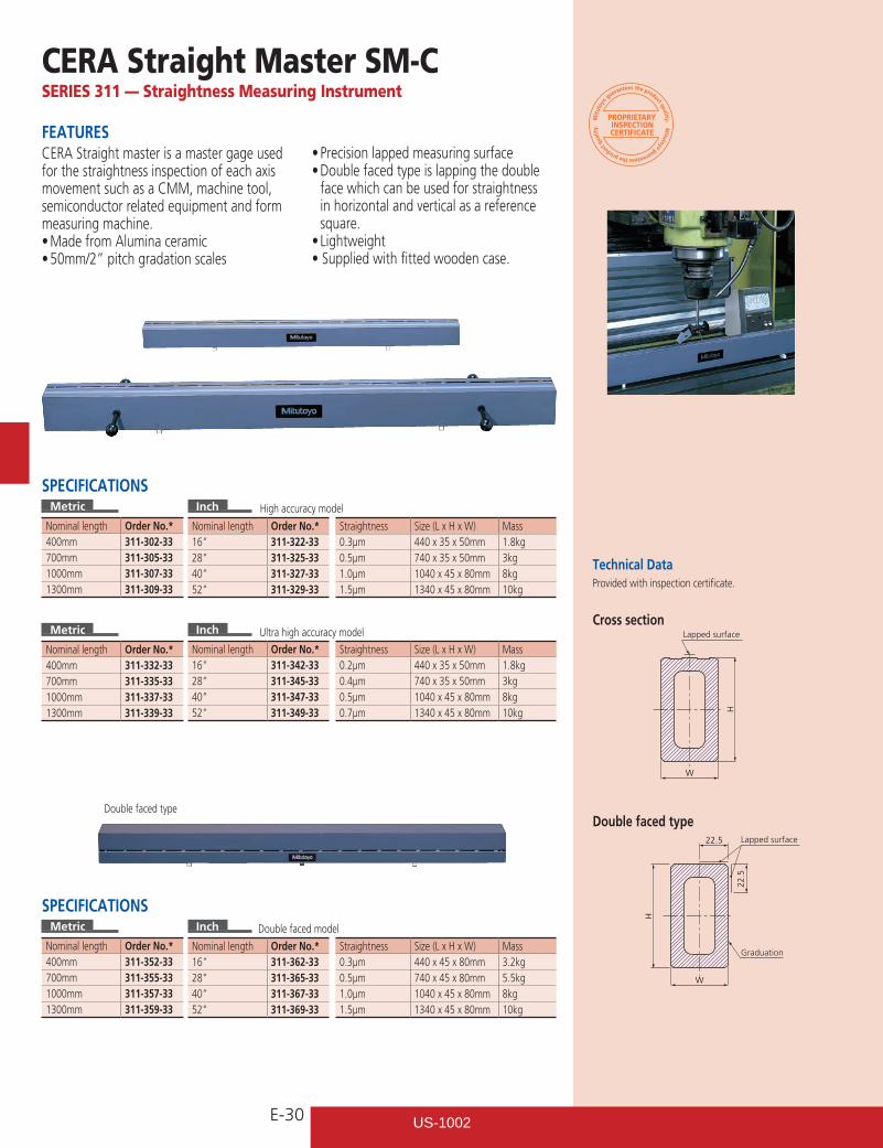
CERA Straight Master SM-CSERIES 311 — Straightness Measuring Instrument
FEATURESCERA Straight master is a master gage used for the straightness inspection of each axis movement such as a CMM, machine tool, semiconductor related equipment and form measuring machine.•MadefromAluminaceramic•50mm/2”pitchgradationscales
•Precisionlappedmeasuringsurface•Doublefacedtypeislappingthedouble
face which can be used for straightness in horizontal and vertical as a reference square.•Lightweight•Suppliedwithfittedwoodencase.
SPECIFICATIONSMetric
Nominal length Order No.*400mm 311-302-33700mm 311-305-331000mm 311-307-331300mm 311-309-33
Inch
Nominal length Order No.* Straightness Size (L x H x W) Mass16” 311-322-33 0.3µm 440 x 35 x 50mm 1.8kg28” 311-325-33 0.5µm 740 x 35 x 50mm 3kg40” 311-327-33 1.0µm 1040 x 45 x 80mm 8kg52” 311-329-33 1.5µm 1340 x 45 x 80mm 10kg
Metric
Nominal length Order No.*400mm 311-332-33700mm 311-335-331000mm 311-337-331300mm 311-339-33
Inch
Nominal length Order No.* Straightness Size (L x H x W) Mass16” 311-342-33 0.2µm 440 x 35 x 50mm 1.8kg28” 311-345-33 0.4µm 740 x 35 x 50mm 3kg40” 311-347-33 0.5µm 1040 x 45 x 80mm 8kg52” 311-349-33 0.7µm 1340 x 45 x 80mm 10kg
SPECIFICATIONSMetric
Nominal length Order No.*400mm 311-352-33700mm 311-355-331000mm 311-357-331300mm 311-359-33
Inch
Nominal length Order No.* Straightness Size (L x H x W) Mass16” 311-362-33 0.3µm 440 x 45 x 80mm 3.2kg28” 311-365-33 0.5µm 740 x 45 x 80mm 5.5kg40” 311-367-33 1.0µm 1040 x 45 x 80mm 8kg52” 311-369-33 1.5µm 1340 x 45 x 80mm 10kg
Provided with inspection certificate.
Cross section
Double faced typeDouble faced type
Ultra high accuracy model
Double faced model
High accuracy model
Technical Data
US-1002
E-31
122
657.
5
50
ø6
Unit: mm
ø6
200
Unit: mm
88Unit: mm
Testindicator
Feeler
6783
7216
5454
2
125
Indicator holder
Connector pin
Indicator holder
Connector pin
125
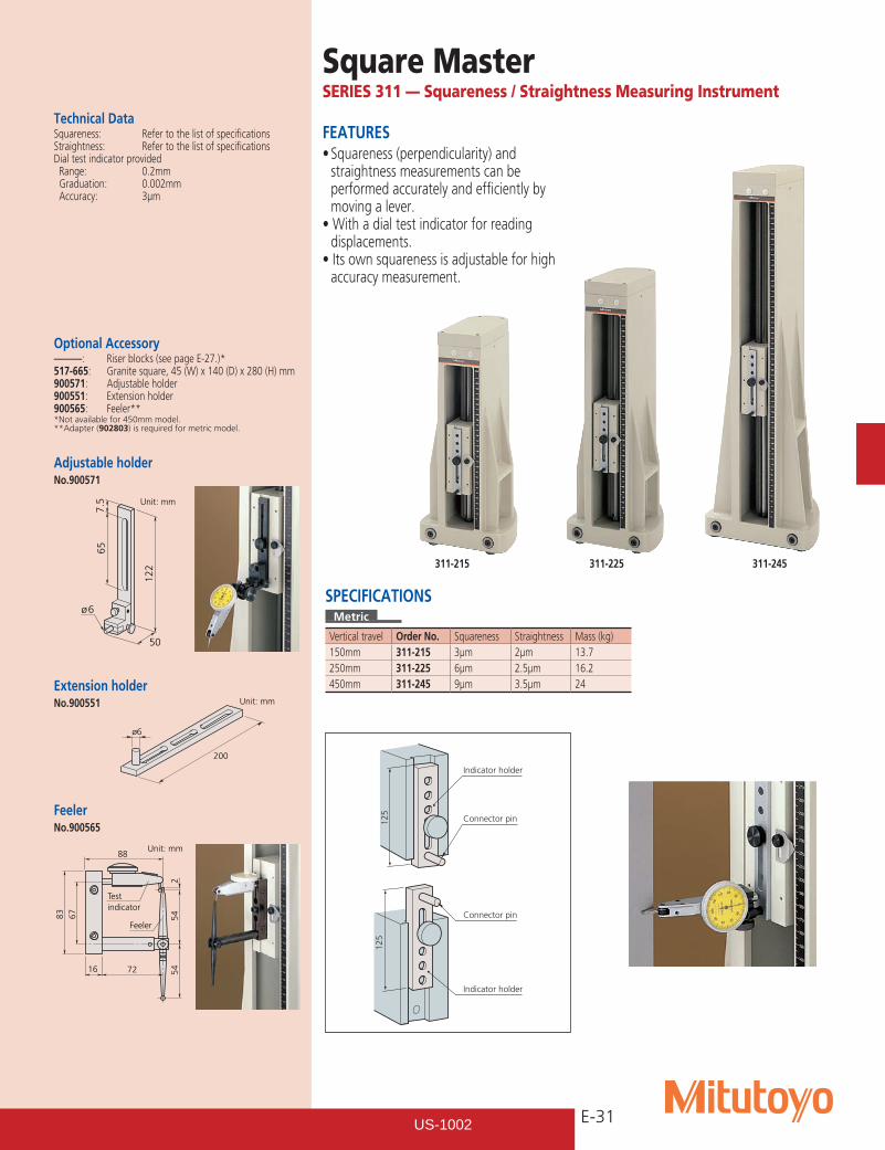
Square MasterSERIES 311 — Squareness / Straightness Measuring Instrument
FEATURES•Squareness(perpendicularity)and
straightness measurements can be performed accurately and efficiently by moving a lever.•Withadialtestindicatorforreading
displacements.•Itsownsquarenessisadjustableforhigh
accuracy measurement.
Optional Accessory––––––: Riser blocks (see page E-27.)*517-665: Granite square, 45 (W) x 140 (D) x 280 (H) mm900571: Adjustable holder900551: Extension holder900565: Feeler***Not available for 450mm model.**Adapter (902803) is required for metric model.
SPECIFICATIONSMetric
Vertical travel Order No. Squareness Straightness Mass (kg)150mm 311-215 3µm 2µm 13.7250mm 311-225 6µm 2.5µm 16.2450mm 311-245 9µm 3.5µm 24
Technical DataSquareness: Refer to the list of specificationsStraightness: Refer to the list of specificationsDial test indicator provided Range: 0.2mm Graduation: 0.002mm Accuracy: 3µm
FeelerNo.900565
Adjustable holderNo.900571
Extension holderNo.900551
311-215 311-225 311-245
US-1002
E-32
2.7
10L
Renge
LRenge
LRenge
Graduation0.1 graduation
0.1mm graduation
0.5mm graduation
1mm graduation
1
22
Graduation
Graduation
2.5
3.5
1.71
.55
4.7
1010.5
36
2.5
3.5
22
5
4.7
101
36
3.5
22
5
1
L
T
Graduation
W
Range
5Alignment mark thickness: 20µm
Graduation thickness: 4µm
42
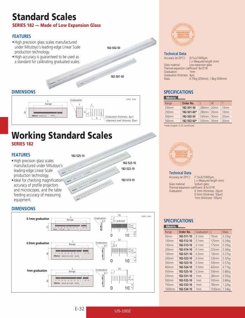
Standard ScalesSERIES 182 — Made of Low Expansion Glass
Technical DataAccuracy (at 20°C): (0.5+L/1000)µm, L = Measured length (mm)Glass material: Low expansion glassThermal expansion coefficient: 8x10⁻⁸/KGraduation: 1mmGraduation thickness: 4µmMass: 0.75kg (250mm), 1.8kg (500mm)
FEATURES•Highprecisionglassscalesmanufactured
under Mitutoyo’s leading-edge Linear Scale production technology.•Highaccuracyisguaranteedtobeusedas
a standard for calibrating graduated scales.
Working Standard ScalesSERIES 182
FEATURES•Highprecisionglassscales
manufactured under Mitutoyo’s leading-edge Linear Scale production technology.•Idealforcheckingmagnification
accuracy of profile projectors and microscopes, and the table feeding accuracy of measuring equipment.
SPECIFICATIONSMetric
Range Order No. L W T250mm 182-501-50 280mm 20mm 10mm250mm 182-501-60* 280mm 20mm 10mm500mm 182-502-50 530mm 30mm 20mm500mm 182-502-60* 530mm 30mm 20mm
*with English JCSS certificate.
Technical DataAccuracy (at 20°C): (1.5+2L/1000)µm, L = Measured length (mm)Glass material: Sodium glassThermal expansion coefficient: 8.5x10⁻⁸/KGraduation: 0.1mm (thickness: 20µm) 0.5mm (thickness: 50µm) 1mm (thickness: 100µm)
SPECIFICATIONSMetric
Range Order No. Graduation L Mass50mm 182-511-10 0.1mm 75mm 0.23kg100mm 182-512-10 0.1mm 125mm 0.24kg150mm 182-513-10 0.1mm 175mm 0.35kg200mm 182-514-10 0.1mm 225mm 0.36kg100mm 182-521-10 0.5mm 130mm 0.27kg200mm 182-522-10 0.5mm 230mm 0.32kg300mm 182-523-10 0.5mm 330mm 0.57kg400mm 182-524-10 0.5mm 430mm 0.71kg500mm 182-525-10 0.5mm 530mm 0.86kg250mm 182-531-10 1mm 280mm 0.55kg500mm 182-532-10 1mm 530mm 0.86kg750mm 182-533-10 1mm 780mm 1.22kg1000mm 182-534-10 1mm 1030mm 1.54kg
DIMENSIONS Unit: mm
DIMENSIONS Unit: mm
182-502-50
182-501-50
182-525-10
182-523-10
182-522-10
182-513-10
US-1002
E-33
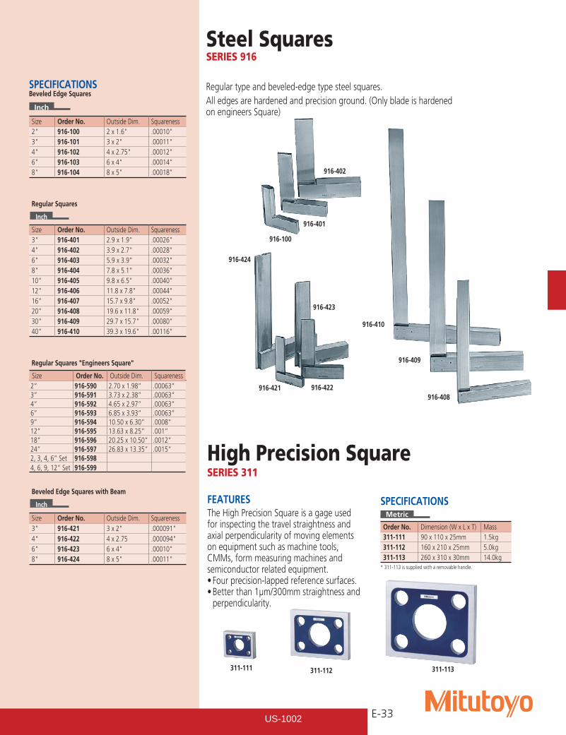
SPECIFICATIONS Beveled Edge Squares
Inch
Size Order No. Outside Dim. Squareness2" 916-100 2x1.6" .00010"3" 916-101 3x2" .00011"4" 916-102 4x2.75" .00012"6" 916-103 6x4" .00014"8" 916-104 8x5" .00018"
Regular Squares
Inch
Size Order No. Outside Dim. Squareness3" 916-401 2.9x1.9" .00026"4" 916-402 3.9x2.7" .00028"6" 916-403 5.9x3.9" .00032"8" 916-404 7.8x5.1" .00036"10" 916-405 9.8x6.5" .00040"12" 916-406 11.8x7.8" .00044"16" 916-407 15.7x9.8" .00052"20" 916-408 19.6x11.8" .00059"30" 916-409 29.7x15.7" .00080"40" 916-410 39.3x19.6" .00116"
Regular Squares "Engineers Square"
Inch
Beveled Edge Squares with Beam
Inch
Size Order No. Outside Dim. Squareness3" 916-421 3x2" .000091"4" 916-422 4 x 2.75 .000094"6" 916-423 6x4" .00010"8" 916-424 8x5" .00011"
Steel SquaresSERIES 916
Regular type and beveled-edge type steel squares.All edges are hardened and precision ground. (Only blade is hardened on engineers Square)
916-100
916-401
916-402
916-424
916-421 916-422
916-423
916-410
916-409
916-408
Size Order No. Outside Dim. Squareness2” 916-590 2.70 x 1.98” .00063”3” 916-591 3.73 x 2.38” .00063”4” 916-592 4.65 x 2.97” .00063”6” 916-593 6.85 x 3.93” .00063”9” 916-594 10.50 x 6.30” .0008”12” 916-595 13.63 x 8.25” .001”18” 916-596 20.25 x 10.50” .0012”24” 916-597 26.83 x 13.35” .0015”2, 3, 4, 6” Set 916-5984, 6, 9, 12” Set 916-599
High Precision SquareSERIES 311
311-111 311-112 311-113
FEATURESThe High Precision Square is a gage used for inspecting the travel straightness and axial perpendicularity of moving elements on equipment such as machine tools, CMMs, form measuring machines and semiconductor related equipment.•Fourprecision-lappedreferencesurfaces.•Betterthan1µm/300mmstraightnessand
perpendicularity.
SPECIFICATIONSMetric
Order No. Dimension (W x L x T) Mass311-111 90 x 110 x 25mm 1.5kg311-112 160 x 210 x 25mm 5.0kg311-113 260 x 310 x 30mm 14.0kg
* 311-113 is supplied with a removable handle.
US-1002
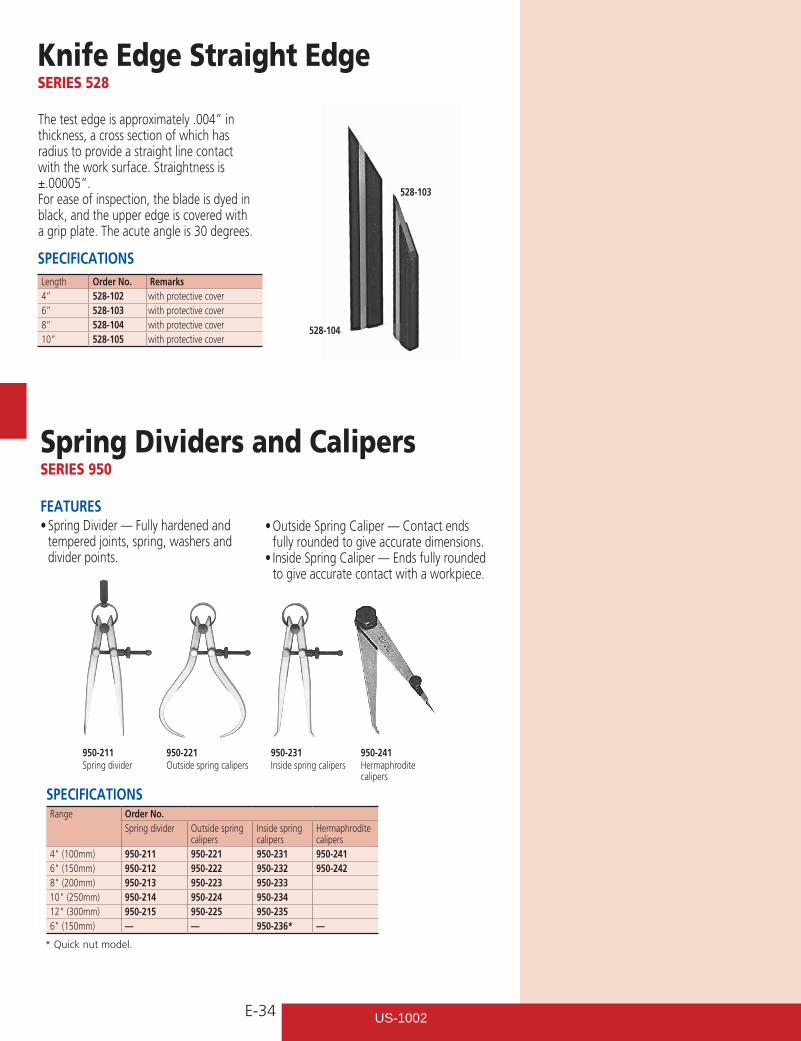
E-34
Knife Edge Straight EdgeSERIES 528
Spring Dividers and CalipersSERIES 950
The test edge is approximately .004” in thickness, a cross section of which has radius to provide a straight line contact with the work surface. Straightness is ±.00005”.
For ease of inspection, the blade is dyed in black, and the upper edge is covered with a grip plate. The acute angle is 30 degrees.
SPECIFICATIONSLength Order No. Remarks4” 528-102 with protective cover6” 528-103 with protective cover8” 528-104 with protective cover10” 528-105 with protective cover
FEATURES•SpringDivider—Fullyhardenedand
tempered joints, spring, washers and divider points.
SPECIFICATIONSRange Order No.
Spring divider Outside spring calipers
Inside spring calipers
Hermaphrodite calipers
4"(100mm) 950-211 950-221 950-231 950-2416"(150mm) 950-212 950-222 950-232 950-2428"(200mm) 950-213 950-223 950-23310"(250mm) 950-214 950-224 950-23412"(300mm) 950-215 950-225 950-2356"(150mm) — — 950-236* —
950-211Spring divider
950-221Outside spring calipers
950-231Inside spring calipers
528-104
528-103
950-241Hermaphrodite calipers
* Quick nut model.
•OutsideSpringCaliper—Contactendsfully rounded to give accurate dimensions.•InsideSpringCaliper—Endsfullyrounded
to give accurate contact with a workpiece.
US-1002
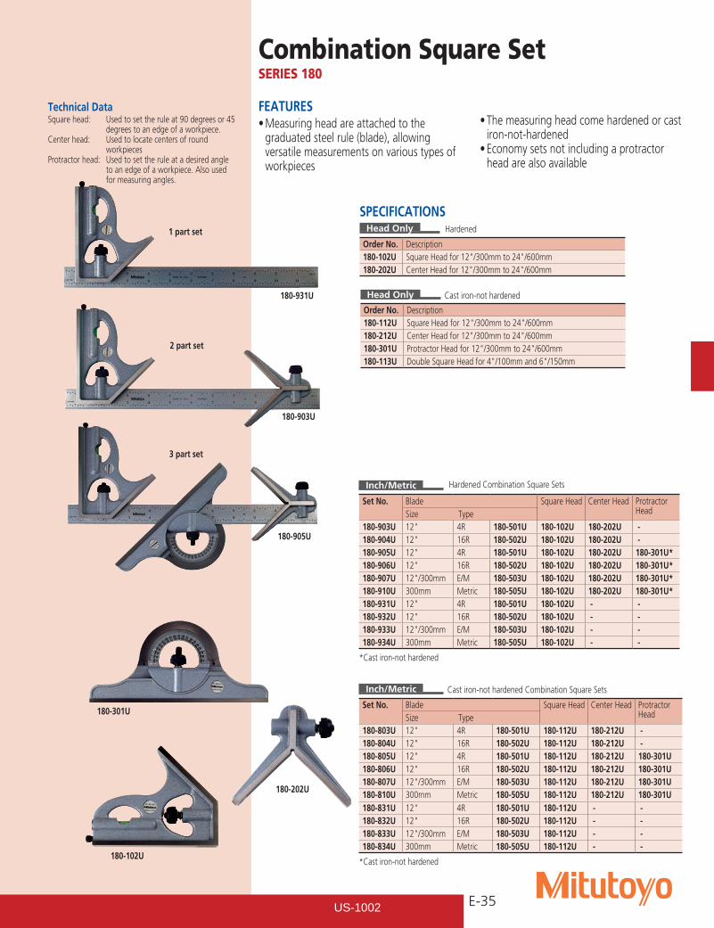
E-35
Combination Square SetSERIES 180
Technical DataSquare head: Used to set the rule at 90 degrees or 45
degrees to an edge of a workpiece.Center head: Used to locate centers of round
workpiecesProtractor head: Used to set the rule at a desired angle
to an edge of a workpiece. Also used for measuring angles.
SPECIFICATIONSHead Only
Order No. Description180-102U SquareHeadfor12"/300mmto24"/600mm180-202U CenterHeadfor12"/300mmto24"/600mm
Inch/Metric
Set No. Blade Square Head Center Head Protractor HeadSize Type
180-903U 12" 4R 180-501U 180-102U 180-202U -180-904U 12" 16R 180-502U 180-102U 180-202U -180-905U 12" 4R 180-501U 180-102U 180-202U 180-301U*180-906U 12" 16R 180-502U 180-102U 180-202U 180-301U*180-907U 12"/300mm E/M 180-503U 180-102U 180-202U 180-301U*180-910U 300mm Metric 180-505U 180-102U 180-202U 180-301U*180-931U 12" 4R 180-501U 180-102U - -180-932U 12" 16R 180-502U 180-102U - -180-933U 12"/300mm E/M 180-503U 180-102U - -180-934U 300mm Metric 180-505U 180-102U - -
*Cast iron-not hardened
Inch/Metric
Set No. Blade Square Head Center Head Protractor HeadSize Type
180-803U 12" 4R 180-501U 180-112U 180-212U -180-804U 12" 16R 180-502U 180-112U 180-212U -180-805U 12" 4R 180-501U 180-112U 180-212U 180-301U180-806U 12" 16R 180-502U 180-112U 180-212U 180-301U180-807U 12"/300mm E/M 180-503U 180-112U 180-212U 180-301U180-810U 300mm Metric 180-505U 180-112U 180-212U 180-301U180-831U 12" 4R 180-501U 180-112U - -180-832U 12" 16R 180-502U 180-112U - -180-833U 12"/300mm E/M 180-503U 180-112U - -180-834U 300mm Metric 180-505U 180-112U - -
*Cast iron-not hardened
FEATURES•Measuringheadareattachedtothe
graduated steel rule (blade), allowing versatile measurements on various types of workpieces
Hardened
Hardened Combination Square Sets
•Themeasuringheadcomehardenedorcastiron-not-hardened•Economysetsnotincludingaprotractor
head are also available
Cast iron-not hardened Combination Square Sets
Cast iron-not hardened
Order No. Description180-112U SquareHeadfor12"/300mmto24"/600mm180-212U CenterHeadfor12"/300mmto24"/600mm180-301U ProtractorHeadfor12"/300mmto24"/600mm180-113U DoubleSquareHeadfor4"/100mmand6"/150mm
Head Only
180-903U
180-905U
180-931U
180-301U
180-102U
180-202U
1 part set
2 part set
3 part set
US-1002
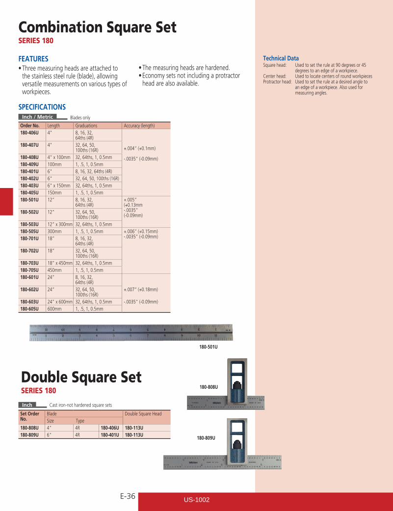
E-36
Combination Square SetSERIES 180
FEATURES•Threemeasuringheadsareattachedto
the stainless steel rule (blade), allowing versatile measurements on various types of workpieces.
Inch / Metric
Order No. Length Graduations Accuracy (length)180-406U 4” 8, 16, 32,
64ths (4R)
+.004” (+0.1mm)
-.0035” (-0.09mm)
180-407U 4” 32, 64, 50, 100ths (16R)
180-408U 4” x 100mm 32, 64ths, 1, 0.5mm180-409U 100mm 1, .5, 1, 0.5mm180-401U 6" 8, 16, 32, 64ths (4R)180-402U 6" 32, 64, 50, 100ths (16R)180-403U 6"x150mm 32, 64ths, 1, 0.5mm180-405U 150mm 1, .5, 1, 0.5mm180-501U 12” 8, 16, 32,
64ths (4R)+.005”(+0.13mm-.0035” (-0.09mm)
180-502U 12” 32, 64, 50, 100ths (16R)
180-503U 12” x 300mm 32, 64ths, 1, 0.5mm180-505U 300mm 1, .5, 1, 0.5mm +.006” (+0.15mm)
-.0035” (-0.09mm)180-701U 18” 8, 16, 32, 64ths (4R)
180-702U 18” 32, 64, 50, 100ths (16R)
180-703U 18” x 450mm 32, 64ths, 1, 0.5mm180-705U 450mm 1, .5, 1, 0.5mm180-601U 24” 8, 16, 32,
64ths (4R)180-602U 24” 32, 64, 50,
100ths (16R)+.007” (+0.18mm)
180-603U 24” x 600mm 32, 64ths, 1, 0.5mm -.0035” (-0.09mm)180-605U 600mm 1, .5, 1, 0.5mm
•Themeasuringheadsarehardened.•Economysetsnotincludingaprotractor
head are also available.
Technical DataSquare head: Used to set the rule at 90 degrees or 45
degrees to an edge of a workpiece.Center head: Used to locate centers of round workpiecesProtractor head: Used to set the rule at a desired angle to
an edge of a workpiece. Also used for measuring angles.
SPECIFICATIONS
Inch
Set Order No.
Blade Double Square HeadSize Type
180-808U 4" 4R 180-406U 180-113U180-809U 6" 4R 180-401U 180-113U
Double Square SetSERIES 180
Cast iron-not hardened square sets
Blades only
180-809U
180-808U
180-501U
US-1002
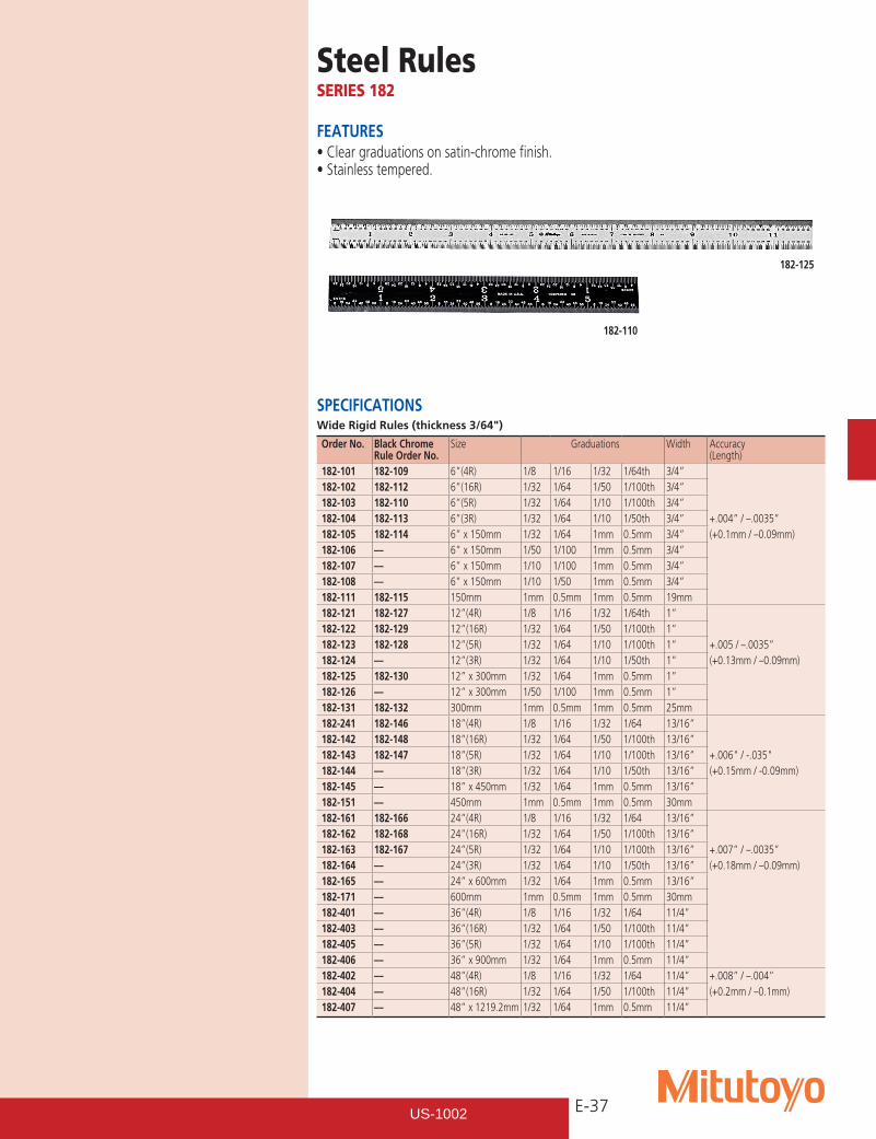
E-37
Steel RulesSERIES 182
FEATURES•Cleargraduationsonsatin-chromefinish.•Stainlesstempered.
182-125
182-110
SPECIFICATIONSWide Rigid Rules (thickness 3/64")
Order No. Black Chrome Rule Order No.
Size Graduations Width Accuracy (Length)
182-101 182-109 6”(4R) 1/8 1/16 1/32 1/64th 3/4” 182-102 182-112 6”(16R) 1/32 1/64 1/50 1/100th 3/4” 182-103 182-110 6”(5R) 1/32 1/64 1/10 1/100th 3/4” 182-104 182-113 6”(3R) 1/32 1/64 1/10 1/50th 3/4” +.004” / –.0035” 182-105 182-114 6” x 150mm 1/32 1/64 1mm 0.5mm 3/4” (+0.1mm / –0.09mm) 182-106 –– 6” x 150mm 1/50 1/100 1mm 0.5mm 3/4” 182-107 –– 6” x 150mm 1/10 1/100 1mm 0.5mm 3/4” 182-108 –– 6” x 150mm 1/10 1/50 1mm 0.5mm 3/4” 182-111 182-115 150mm 1mm 0.5mm 1mm 0.5mm 19mm 182-121 182-127 12”(4R) 1/8 1/16 1/32 1/64th 1” 182-122 182-129 12”(16R) 1/32 1/64 1/50 1/100th 1” 182-123 182-128 12”(5R) 1/32 1/64 1/10 1/100th 1” +.005 / –.0035” 182-124 –– 12”(3R) 1/32 1/64 1/10 1/50th 1” (+0.13mm / –0.09mm) 182-125 182-130 12” x 300mm 1/32 1/64 1mm 0.5mm 1” 182-126 –– 12” x 300mm 1/50 1/100 1mm 0.5mm 1” 182-131 182-132 300mm 1mm 0.5mm 1mm 0.5mm 25mm 182-241 182-146 18”(4R) 1/8 1/16 1/32 1/64 13/16” 182-142 182-148 18”(16R) 1/32 1/64 1/50 1/100th 13/16” 182-143 182-147 18”(5R) 1/32 1/64 1/10 1/100th 13/16” +.006"/-.035" 182-144 –– 18”(3R) 1/32 1/64 1/10 1/50th 13/16” (+0.15mm / -0.09mm) 182-145 –– 18” x 450mm 1/32 1/64 1mm 0.5mm 13/16” 182-151 –– 450mm 1mm 0.5mm 1mm 0.5mm 30mm 182-161 182-166 24”(4R) 1/8 1/16 1/32 1/64 13/16” 182-162 182-168 24”(16R) 1/32 1/64 1/50 1/100th 13/16” 182-163 182-167 24”(5R) 1/32 1/64 1/10 1/100th 13/16” +.007” / –.0035” 182-164 –– 24”(3R) 1/32 1/64 1/10 1/50th 13/16” (+0.18mm / –0.09mm) 182-165 –– 24” x 600mm 1/32 1/64 1mm 0.5mm 13/16” 182-171 –– 600mm 1mm 0.5mm 1mm 0.5mm 30mm 182-401 –– 36”(4R) 1/8 1/16 1/32 1/64 11/4” 182-403 –– 36”(16R) 1/32 1/64 1/50 1/100th 11/4” 182-405 –– 36”(5R) 1/32 1/64 1/10 1/100th 11/4” 182-406 –– 36” x 900mm 1/32 1/64 1mm 0.5mm 11/4” 182-402 –– 48”(4R) 1/8 1/16 1/32 1/64 11/4” +.008” / –.004” 182-404 –– 48”(16R) 1/32 1/64 1/50 1/100th 11/4” (+0.2mm / –0.1mm) 182-407 –– 48” x 1219.2mm 1/32 1/64 1mm 0.5mm 11/4”
US-1002
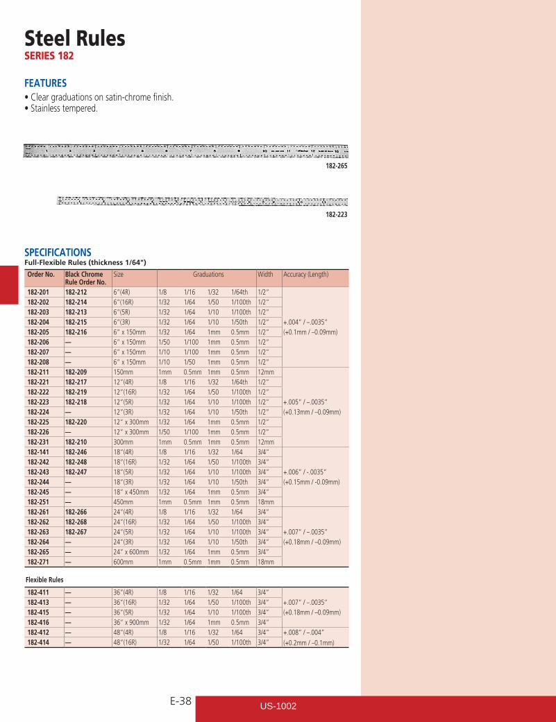
E-38
Steel RulesSERIES 182
FEATURES•Cleargraduationsonsatin-chromefinish.•Stainlesstempered.
SPECIFICATIONSFull-Flexible Rules (thickness 1/64")
Order No. Black Chrome Rule Order No.
Size Graduations Width Accuracy (Length)
182-201 182-212 6”(4R) 1/8 1/16 1/32 1/64th 1/2” 182-202 182-214 6”(16R) 1/32 1/64 1/50 1/100th 1/2” 182-203 182-213 6”(5R) 1/32 1/64 1/10 1/100th 1/2” 182-204 182-215 6”(3R) 1/32 1/64 1/10 1/50th 1/2” +.004” / –.0035” 182-205 182-216 6” x 150mm 1/32 1/64 1mm 0.5mm 1/2” (+0.1mm / –0.09mm) 182-206 –– 6” x 150mm 1/50 1/100 1mm 0.5mm 1/2” 182-207 –– 6” x 150mm 1/10 1/100 1mm 0.5mm 1/2” 182-208 –– 6” x 150mm 1/10 1/50 1mm 0.5mm 1/2” 182-211 182-209 150mm 1mm 0.5mm 1mm 0.5mm 12mm 182-221 182-217 12”(4R) 1/8 1/16 1/32 1/64th 1/2” 182-222 182-219 12”(16R) 1/32 1/64 1/50 1/100th 1/2” 182-223 182-218 12”(5R) 1/32 1/64 1/10 1/100th 1/2” +.005” / –.0035” 182-224 –– 12”(3R) 1/32 1/64 1/10 1/50th 1/2” (+0.13mm / –0.09mm) 182-225 182-220 12” x 300mm 1/32 1/64 1mm 0.5mm 1/2” 182-226 –– 12” x 300mm 1/50 1/100 1mm 0.5mm 1/2” 182-231 182-210 300mm 1mm 0.5mm 1mm 0.5mm 12mm 182-141 182-246 18”(4R) 1/8 1/16 1/32 1/64 3/4” 182-242 182-248 18”(16R) 1/32 1/64 1/50 1/100th 3/4” 182-243 182-247 18”(5R) 1/32 1/64 1/10 1/100th 3/4” +.006” / -.0035” 182-244 –– 18”(3R) 1/32 1/64 1/10 1/50th 3/4” (+0.15mm / -0.09mm) 182-245 –– 18” x 450mm 1/32 1/64 1mm 0.5mm 3/4” 182-251 –– 450mm 1mm 0.5mm 1mm 0.5mm 18mm 182-261 182-266 24”(4R) 1/8 1/16 1/32 1/64 3/4” 182-262 182-268 24”(16R) 1/32 1/64 1/50 1/100th 3/4” 182-263 182-267 24”(5R) 1/32 1/64 1/10 1/100th 3/4” +.007” / –.0035” 182-264 –– 24”(3R) 1/32 1/64 1/10 1/50th 3/4” (+0.18mm / –0.09mm) 182-265 –– 24” x 600mm 1/32 1/64 1mm 0.5mm 3/4” 182-271 –– 600mm 1mm 0.5mm 1mm 0.5mm 18mm Flexible Rules
182-411 –– 36”(4R) 1/8 1/16 1/32 1/64 3/4” 182-413 –– 36”(16R) 1/32 1/64 1/50 1/100th 3/4” +.007” / –.0035” 182-415 –– 36”(5R) 1/32 1/64 1/10 1/100th 3/4” (+0.18mm / –0.09mm) 182-416 –– 36” x 900mm 1/32 1/64 1mm 0.5mm 3/4” 182-412 –– 48”(4R) 1/8 1/16 1/32 1/64 3/4” +.008” / –.004”
(+0.2mm / –0.1mm) 182-414 –– 48”(16R) 1/32 1/64 1/50 1/100th 3/4”
182-265
182-223
US-1002
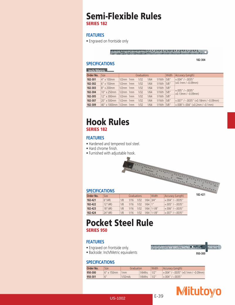
E-39
Semi-Flexible RulesSERIES 182
FEATURES•Engravedonfrontsideonly
SPECIFICATIONSInch/Metric
Order No. Size Graduations Width Accuracy (Length)182-301 4” x 100mm 1/2mm 1mm 1/32 1/64 1/16th 5/8” +.004” / –.0035”
(+0.1mm / –0.09mm)182-302 6” x 150mm 1/2mm 1mm 1/32 1/64 1/16th 5/8”182-303 8” x 200mm 1/2mm 1mm 1/32 1/64 1/16th 5/8”
+.005” / –.0035” +0.13mm / –0.09mm)182-304 10” x 250mm 1/2mm 1mm 1/32 1/64 1/16th 5/8”
182-305 12” x 300mm 1/2mm 1mm 1/32 1/64 1/16th 5/8”182-307 20” x 500mm 1/2mm 1mm 1/32 1/64 1/16th 5/8” +.007” / –.0035” (+0.18mm / –0.09mm)182-309 40” x 1000mm 1/2mm 1mm 1/32 1/64 1/16th 5/8” +.008”/–.004” (+0.2mm / –0.1mm)
182-304
Hook RulesSERIES 182
FEATURES•Hardenedandtemperedtoolsteel.•Hardchromefinish.•Furnishedwithadjustablehook.
SPECIFICATIONSOrder No. Size Graduations Width Accuracy (Length)182-421 6”(4R) 1/8 1/16 1/32 1/64 3/4” +.004” / –.0035”182-422 12”(4R) 1/8 1/16 1/32 1/64 1” +.005” / –.0035”182-423 18”(4R) 1/8 1/16 1/32 1/64 1-1/8” +.006” / –.0035”182-424 24”(4R) 1/8 1/16 1/32 1/64 1-1/8” +.007” / –.0035”
182-421
Pocket Steel RuleSERIES 950
FEATURES•Engravedonfrontsideonly.•Backside:Inch/Metricequivalents
SPECIFICATIONSOrder No. Size Graduation Width Accuracy (Length)950-300 6” x 150mm 1mm 1/64ths 1/2” +.004” / –.0035” (+0.1mm / –0.09mm)950-301 6” 1/32mds 1/64ths 1/2” +.004” / –.0035”
950-300
US-1002
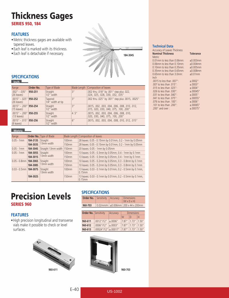
E-40
Thickness GagesSERIES 950, 184
FEATURES•Metricthicknessgagesareavailablewith
tapered leaves.•Eachleafismarkedwithitsthickness.•Eachleafisdetachableifnecessary. 184-304S
Precision LevelsSERIES 960
FEATURES•Highprecisionlongitudinalandtransverse
vials make it possible to check or level surfaces.
SPECIFICATIONSOrder No. Sensitivity Accuracy Dimensions
(W x D x H)960-703 0.02mm/m ±0.006mm 200 x 44 x 200mm
Technical DataAccuracy of Leaves ThicknessNominal Thickness ToleranceMetric0.01mm to less than 0.06mm: ±0.003mm0.06mm to less than 0.10mm: ±0.004mm0.10mm to less than 0.35mm: ±0.005mm0.35mm to less than 0.65mm: ±0.008mm0.65mm to less than 3.0mm: ±0.01mmInch.0015tolessthan.007": ±.0002".007tolessthan.015": ±.0003".015tolessthan.025": ±.0004".026tolessthan.030": ±.00045".031tolessthan.040": ±.0005".041tolessthan.075": ±.00055".076tolessthan.100": ±.0006".101tolessthan.200": ±.00065".200"andover: ±.00075"
960-611 960-703
Order No. Sensitivity Accuracy DimensionsW D H
960-611 .0012”/12” ±.0006” 7.87” 1.73” 1.50”960-612 .0006”/12” ±.0003” 7.87” 1.73” 1.50”960-613 .00024”/12” ±.00017” 7.87” 1.73” 1.50”
SPECIFICATIONSInch
Range Order No. Type of Blade Blade Length Composition of leaves.002” - .035” (26 leaves)
950-251 Straight 1/2” width
3” .002 thru .018” by .001” step plus .022, .024, .025, .028, .030, .032, .035”
.0015” - .025” (26 leaves)
950-252 Tapered 1/4” width at tip
3” .002 thru .025” by .001” step plus .0015, .0025”
.0015” - .200” (15 leaves)
950-254 Straight 1/2” width
3” .0015, .002, .003, .004, .006, .008, .010, .012, .015, .020, .030, .040, .075, .100, .200”
.0015” - .200” (13 leaves)
950-255 Straight 1/2” width
4 .5” .0015, .002, .003, .004, .006, .008, .010, .020, .030, .040, .075, .100, .200”
.0015” - .015” (8 leaves)
950-256 Straight 1/2” width
6” .0015, .002, .003, .004, .008, .010, .012, .015”
Metric
Range Order No. Type of Blade Blade Length Composition of leaves0.05 - 1mm 184-313S Straight
13mm width100mm 28 leaves: 0.05 - 0.15mm by 0.01mm, 0.2 - 1mm by 0.05mm
184-303S 150mm 28 leaves: 0.05 - 0.15mm by 0.01mm, 0.2 - 1mm by 0.05mm0.05 - 1mm 184-304S Straight 13mm width 150mm 20 leaves: 0.05 - 1mm by 0.05mm0.05 - 1mm 184-305S Straight
13mm width100mm 13 leaves: 0.05 - 0.3mm by 0.05mm, 0.4 - 1mm by 0.1mm
184-301S 150mm 13 leaves: 0.05 - 0.3mm by 0.05mm, 0.4 - 1mm by 0.1mm0.05 - 0.8mm 184-306S Straight
13mm width100mm 10 leaves: 0.05 - 0.2mm by 0.05mm, 0.3 - 0.8mm by 0.1mm
184-308S 150mm 10 leaves: 0.05 - 0.2mm by 0.05mm, 0.3 - 0.8mm by 0.1mm0.03 - 0.5mm 184-307S Straight
13mm width100mm 13 leaves: 0.03 - 0.1mm by 0.01mm, 0.2 - 0.5mm by 0.1mm,
0.15mm184-302S 150mm 13 leaves: 0.03 - 0.1mm by 0.01mm, 0.2 - 0.5mm by 0.1mm,
0.15mm
US-1002
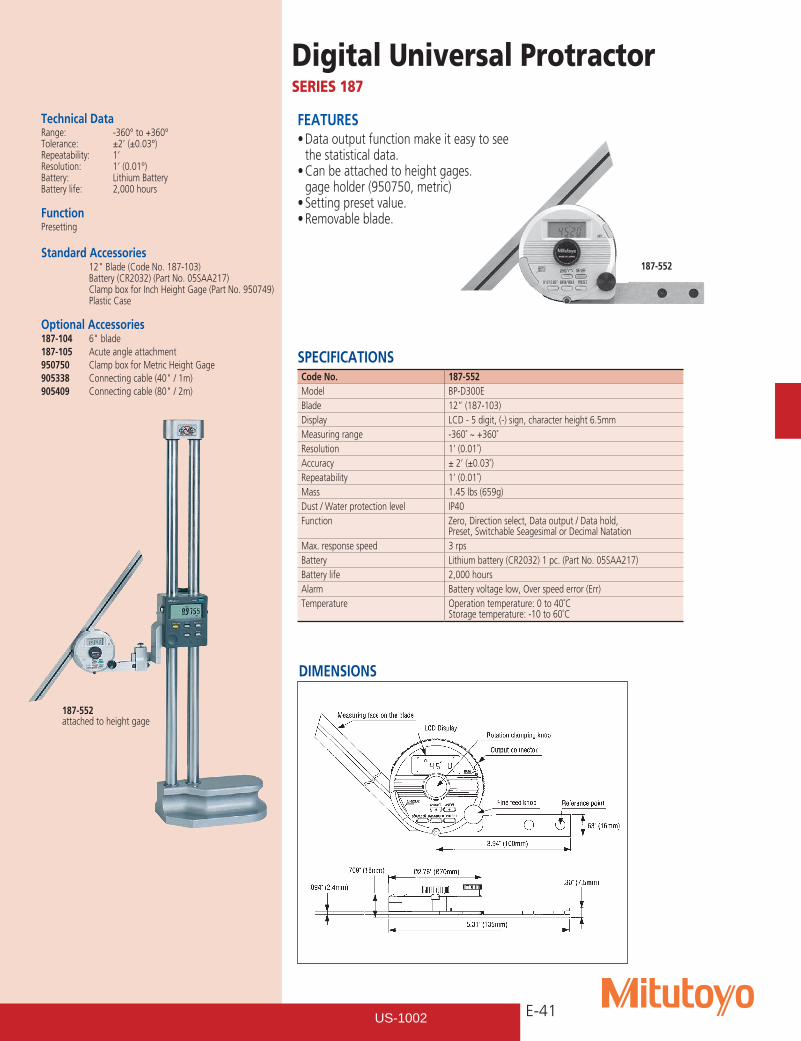
E-41
Digital Universal ProtractorSERIES 187
FEATURES•Dataoutputfunctionmakeiteasytosee
the statistical data.•Canbeattachedtoheightgages.
gage holder (950750, metric)•Settingpresetvalue.•Removableblade.
Technical DataRange: -360° to +360°Tolerance: ±2’ (±0.03°)Repeatability: 1’Resolution: 1’ (0.01°)Battery: Lithium BatteryBattery life: 2,000 hours
FunctionPresetting
Standard Accessories 12"Blade(CodeNo.187-103) Battery (CR2032) (Part No. 05SAA217) Clamp box for Inch Height Gage (Part No. 950749) Plastic Case
Optional Accessories187-104 6"blade187-105 Acute angle attachment950750 Clamp box for Metric Height Gage905338 Connectingcable(40"/1m)905409 Connectingcable(80"/2m)
187-552 attached to height gage
SPECIFICATIONSCode No. 187-552Model BP-D300EBlade 12” (187-103)Display LCD - 5 digit, (-) sign, character height 6.5mmMeasuring range -360˚ ~ +360˚Resolution 1’ (0.01˚)Accuracy ± 2’ (±0.03˚)Repeatability 1’ (0.01˚)Mass 1.45 lbs (659g)Dust / Water protection level IP40Function Zero, Direction select, Data output / Data hold,
Preset, Switchable Seagesimal or Decimal NatationMax. response speed 3 rpsBattery Lithium battery (CR2032) 1 pc. (Part No. 05SAA217)Battery life 2,000 hoursAlarm Battery voltage low, Over speed error (Err)Temperature Operation temperature: 0 to 40˚C
Storage temperature: -10 to 60˚C
187-552
DIMENSIONS
US-1002
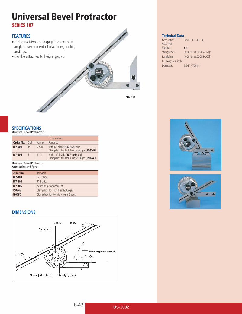
E-42
Universal Bevel ProtractorSERIES 187
FEATURES•High-precisionanglegageforaccurate
angle measurement of machines, molds, and jigs.•Canbeattachedtoheightgages.
Technical DataGraduation: 5min. (0˚ - 90˚ - 0˚) Accuracy Vernier ±5’
Straightness [.00016"+(.00005xL/2)]"
Parallelism [.00016"+(.00005xL/2)]"
L = Length in inch
Diameter: 2.56"/70mm
187-904
SPECIFICATIONSUniversal Bevel Protractors
Graduation Order No. Dial Vernier Remarks187-904 1° 5 min with 6” blade (187-104) and
Clamp box for Inch Height Gages (950749)187-906 1° 5min with 12” blade (187-103) and
Clamp box for Inch Height Gages (950749)
Universal Bevel Protractor Accessories and Parts
Order No. Remarks187-103 12” Blade.187-104 6” Blade.187-105 Acute angle attachment950749 Clamp box for Inch Height Gages950750 Clamp box for Metric Height Gages
DIMENSIONS
US-1002

E-43
SPECIFICATIONS Rectangular Base Protractor
Order No. Graduation Remarks968-201 1° Protractor Graduation: 0°–90°,90°–180°,
180°–90°, 90°–0°968-202 1° Semi-Circle: 0°-180°, 180°-0°968-203* Rectangle: 0°-180°, 180°-0°
*6” Arm with graduation rule.
.05"
2.36
"
.55"
R45
3.70"
6.18"8.03"
MADE IN JAPAN
00000000
00
00
00
00
0000
00 0000
00
00
00
00
ProtractorSERIES 968
Basegular Base Protractor’s scale plate and indicator blade are made entirely of stainless steel. (968-201) (968-202 and 986-203 Satin chrome finish). With 6” arm.
968-201
968-202
968-203
DIMENSIONS
Bevel ProtractorSERIES 187
FEATURES•Consists of three sheetsof stainless steel,
the middle one of which is made for angle measurements.
SPECIFICATIONSOrder No. Graduation Remarks187-201 1˚ / 5 min Center black knob locks
the blade positionProtractor Graduation: 0°–90°, 90°–0°
Technical DataGraduation: 5 min. (0° - 90° - 0°)Blade edge angle: 30° and 60°Diameter: 2.56” / 70mm
187-201
US-1002
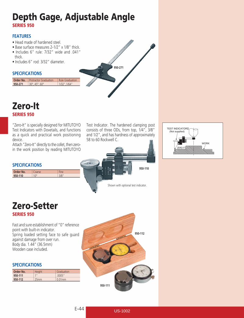
E-44
Depth Gage, Adjustable AngleSERIES 950
SPECIFICATIONS
FEATURES•Headmadeofhardenedsteel.•Basesurfacemeasures2-1/2”x1/8”thick.• Includes 6” rule: 7/32”wide and .041”
thick.•Includes6”rod:3/32”diameter.
950-271
Order No. Protractor Graduation Rule Graduation950-271 30°, 45°, 60° 1/32”,1/64”
Zero-ItSERIES 950
SPECIFICATIONS
”Zero-It” is specially designed for MITUTOYO Test Indicators with Dovetails, and functions as a quick and practical work positioning device.Attach"Zero-It"directlytothecollet,thenzero-in the work position by reading MITUTOYO
Test Indicator. The hardened clamping post consists of three ODs, from top, 1/4”, 3/8” and 1/2”, and has hardness of approximately 58 to 60 Rockwell C.
950-110Order No. Coarse Fine950-110 10° 3/8”
Zero-SetterSERIES 950
SPECIFICATIONS
Fast and sure establishment of “0” reference point with built-in indicator.Spring loaded setting face to safe guard against damage from over run.Body dia. 1.44” (36.5mm) Wooden case included.
950-112
Order No. Height Graduation950-111 1" .0005"950-112 25mm 0.01mm
950-111
WORK
TEST INDICATOR�(Not supplied)
ZERO IT
Shown with optional test indicator.
US-1002
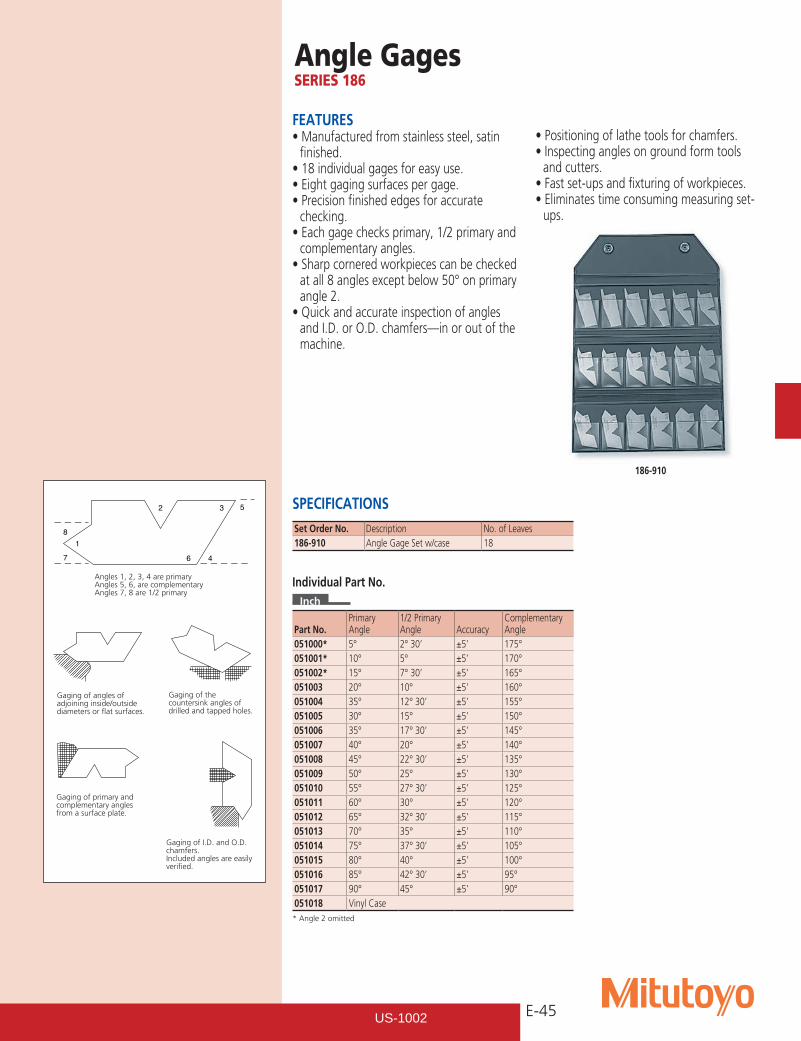
E-45
Angle GagesSERIES 186
FEATURES•Manufacturedfromstainlesssteel,satin
finished.•18individualgagesforeasyuse.•Eightgagingsurfacespergage.•Precisionfinishededgesforaccurate
checking.•Eachgagechecksprimary,1/2primaryand
complementary angles.•Sharpcorneredworkpiecescanbechecked
at all 8 angles except below 50° on primary angle 2.•Quickandaccurateinspectionofangles
and I.D. or O.D. chamfers—in or out of the machine.
•Positioningoflathetoolsforchamfers.•Inspectinganglesongroundformtools
and cutters.•Fastset-upsandfixturingofworkpieces.•Eliminatestimeconsumingmeasuringset-
ups.
SPECIFICATIONS
186-910
* Angle 2 omitted
Part No.PrimaryAngle
1/2 PrimaryAngle Accuracy
ComplementaryAngle
051000* 5° 2° 30’ ±5’ 175°051001* 10° 5° ±5’ 170°051002* 15° 7° 30’ ±5’ 165°051003 20° 10° ±5’ 160°051004 35° 12° 30’ ±5’ 155°051005 30° 15° ±5’ 150°051006 35° 17° 30’ ±5’ 145°051007 40° 20° ±5’ 140°051008 45° 22° 30’ ±5’ 135°051009 50° 25° ±5’ 130°051010 55° 27° 30’ ±5’ 125°051011 60° 30° ±5’ 120°051012 65° 32° 30’ ±5’ 115°051013 70° 35° ±5’ 110°051014 75° 37° 30’ ±5’ 105°051015 80° 40° ±5’ 100°051016 85° 42° 30’ ±5’ 95°051017 90° 45° ±5’ 90°051018 Vinyl Case
8
7
1
2 3 5
6 4
Angles 1, 2, 3, 4 are primaryAngles 5, 6, are complementaryAngles 7, 8 are 1/2 primary
Gaging of angles of adjoining inside/outside diameters or flat surfaces.
Gaging of the countersink angles of drilled and tapped holes.
Gaging of primary and complementary angles from a surface plate.
Gaging of I.D. and O.D. chamfers.Included angles are easily verified.
Set Order No. Description No. of Leaves186-910 Angle Gage Set w/case 18
Individual Part No.Inch
US-1002
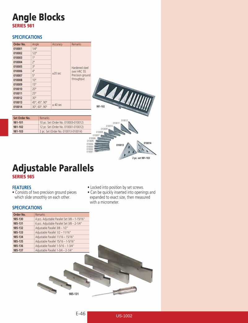
E-46
Angle BlocksSERIES 981
SPECIFICATIONSOrder No. Angle Accuracy Remarks010001 1/4°
±20 sec
Hardened steel over HRC 55 Precision ground throughput
010002 1/2°010003 1°010004 2°010005 3°010006 4°010007 5°010008 10°010009 15°010010 20°010011 25°010012 30°010013 45°, 45°, 90°
± 40 sec010014 30°, 60°, 90°
Set Order No. Remarks981-101 10 pc. Set (Order No. 010003-010012)981-102 12 pc. Set (Order No. 010001-010012)981-103 2 pc. Set (Order No. 010013-010014)
Adjustable ParallelsSERIES 985
SPECIFICATIONS
FEATURES•Consistsoftwoprecisiongroundpieces
which slide smoothly on each other.
•Lockedintopositionbysetscrews.•Canbequicklyinsertedintoopeningsand
expanded to exact size, then measured with a micrometer.
Order No. Remarks985-130 4 pcs. Adjustable Parallel Set 3/8 – 1-15/16”985-131 6 pcs. Adjustable Parallel Set 3/8 – 2-1/4”985-132 Adjustable Parallel 3/8 – 1/2”985-133 Adjustable Parallel 1/2 – 11/16”985-134 Adjustable Parallel 11/16 – 15/16”985-135 Adjustable Parallel 15/16 – 1-5/16”985-136 Adjustable Parallel 1-5/16 – 1-3/4”985-137 Adjustable Parallel 1-3/4 – 2-1/4”
985-131
981-102
010013010014
010012010011
010010010009
010008010007
010006010005010004010003010002010001
2 pc. set 981-103
US-1002
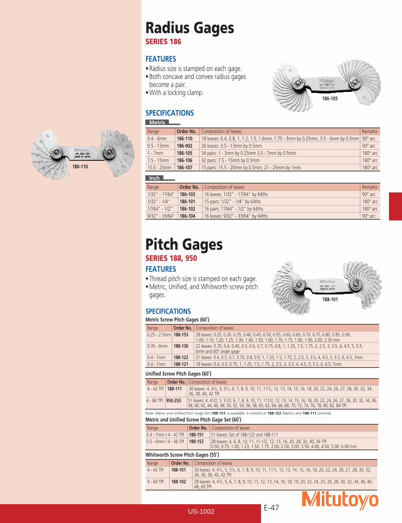
E-47
Radius GagesSERIES 186
Pitch GagesSERIES 188, 950
FEATURES•Radiussizeisstampedoneachgage.•Bothconcaveandconvexradiusgages
become a pair.•Withalockingclamp.
FEATURES•Threadpitchsizeisstampedoneachgage.•Metric,Unified,andWhitworthscrewpitch
gages.
SPECIFICATIONSMetric
Range Order No. Composition of leaves Remarks0.4 - 6mm 186-110 18 leaves: 0.4, 0.8, 1, 1.2, 1.5, 1.6mm, 1.75 - 3mm by 0.25mm, 3.5 - 6mm by 0.5mm 90° arc0.5 - 13mm 186-902 26 leaves: 0.5 - 13mm by 0.5mm 90° arc1 - 7mm 186-105 34 pairs: 1 - 3mm by 0.25mm 3.5 - 7mm by 0.5mm 180° arc7.5 - 15mm 186-106 32 pairs: 7.5 - 15mm by 0.5mm 180° arc15.5 - 25mm 186-107 15 pairs: 15.5 - 20mm by 0.5mm, 21 - 25mm by 1mm 180° arc
Inch
Range Order No. Composition of leaves Remarks1/32"-17/64" 186-103 16leaves:1/32"-17/64"by64ths 90° arc1/32"-1/4" 186-101 15pairs:1/32"-1/4"by64ths 180° arc17/64"-1/2" 186-102 16pairs:17/64"-1/2"by64ths 180° arc9/32"-33/64" 186-104 16leaves:9/32"-33/64"by64ths 90° arc
186-105
186-110
188-101
SPECIFICATIONSMetric Screw Pitch Gages (60˚)Range Order No. Composition of leaves0.25 - 2.5mm 188-153 28 leaves: 0.25, 0.30. 0.35, 0.40, 0.45, 0.50, 0.55, 0.60, 0.65, 0.70, 0.75, 0.80, 0.85, 0.90,
1.00, 1.10, 1.20, 1.25, 1.30, 1.40, 1.50, 1.60, 1.70, 1.75, 1.80, 1.90, 2.00. 2.50 mm 0.35 - 6mm 188-130 22 leaves: 0.35, 0.4, 0.45, 0.5, 0.6, 0.7, 0.75, 0.8, 1, 1.25, 1.5, 1.75, 2, 2.5, 3, 3.5, 4, 4.5, 5, 5.5,
6mm and 60° angle gage 0.4 - 7mm 188-122 21 leaves: 0.4, 0.5, 0.7, 0.75, 0.8, 0.9, 1, 1.25, 1.5, 1.75, 2, 2.5, 3, 3.5, 4, 4.5, 5, 5.5, 6, 6.5, 7mm 0.4 - 7mm 188-121 18 leaves: 0.4, 0.5, 0.75, 1, 1.25, 1.5, 1.75, 2, 2.5, 3, 3.5, 4, 4.5, 5, 5.5, 6, 6.5, 7mm
Unified Screw Pitch Gages (60˚)Range Order No. Composition of leaves4 - 42 TPI 188-111 30 leaves: 4, 41/2, 5, 51/2, 6, 7, 8, 9, 10, 11, 111/2, 12, 13, 14, 15, 16, 18, 20, 22, 24, 26, 27, 28, 30, 32, 34,
36, 38, 40, 42 TPI 4 - 84 TPI 950-253 51 leaves: 4, 41/2, 5, 51/2, 6, 7, 8, 9, 10, 11, 111/2, 12, 13, 14, 15, 16, 18, 20, 22, 24, 26, 27, 28, 30, 32, 34, 36,
38, 40, 42, 44, 46, 48, 50, 52, 54, 56, 58, 60, 62, 64, 66, 68, 70, 72, 74, 76, 78, 80, 82, 84 TPI
Note: Metric and Unified Pitch Gage Set (188-151) is available. It consists of 188-122 (Metric) and 188-111 (Unified).
Whitworth Screw Pitch Gages (55˚)Range Order No. Composition of leaves4 - 42 TPI 188-101 30 leaves: 4, 41/2, 5, 51/2, 6, 7, 8, 9, 10, 11, 111/2, 12, 13, 14, 15, 16, 18, 20, 22, 24, 26, 27, 28, 30, 32,
34, 36, 38, 40, 42 TPI 4 - 60 TPI 188-102 28 leaves: 4, 41/2, 5, 6, 7, 8, 9, 10, 11, 12, 13, 14, 16, 18, 19, 20, 22, 24, 25, 26, 28, 30, 32, 34, 36, 40,
48, 60 TPI
Metric and Unified Screw Pitch Gage Set (60˚)Range Order No. Composition of leaves0.4 - 7mm / 4 - 42 TPI 188-151 51 leaves: Set of 188-122 and 188-111 0.5 - 6mm / 4 - 56 TPI 188-152 28 leaves: 4, 6, 8, 10, 11, 11-1/2, 12, 13, 16, 20, 28, 32, 40, 56 TPI
0.50, 0.75, 1.00, 1.23, 1.50, 1.75, 2.00, 2.50, 3.00, 3.50, 4.00, 4.50, 5.00. 6.00 mm
US-1002
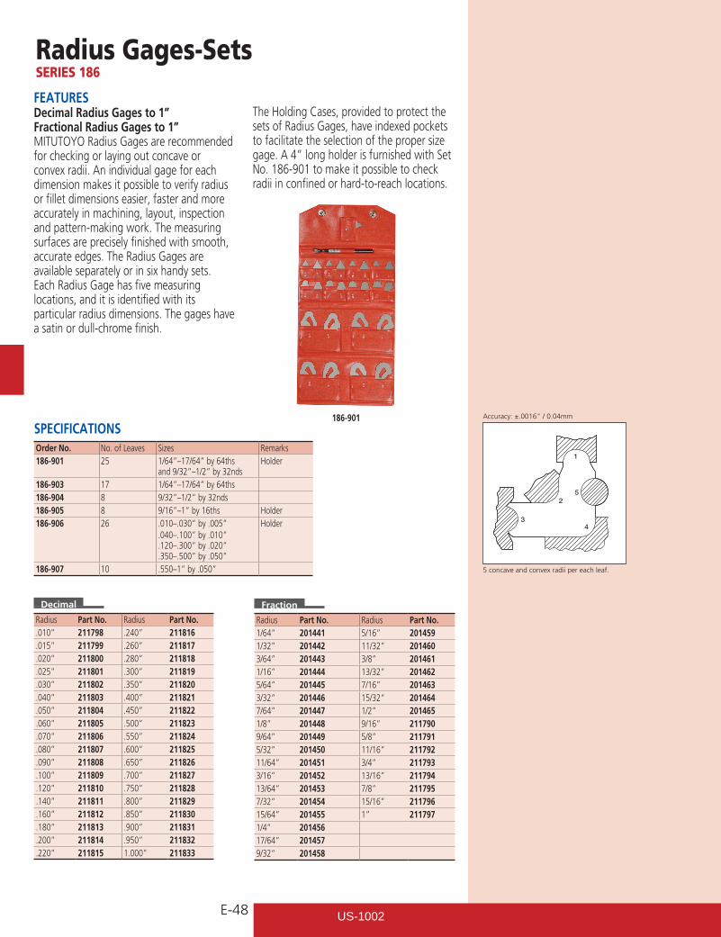
E-48
Radius Gages-SetsSERIES 186
FEATURESDecimal Radius Gages to 1”Fractional Radius Gages to 1”MITUTOYO Radius Gages are recommended for checking or laying out concave or convex radii. An individual gage for each dimension makes it possible to verify radius or fillet dimensions easier, faster and more accurately in machining, layout, inspection and pattern-making work. The measuring surfaces are precisely finished with smooth, accurate edges. The Radius Gages are available separately or in six handy sets.Each Radius Gage has five measuring locations, and it is identified with its particular radius dimensions. The gages have a satin or dull-chrome finish.
The Holding Cases, provided to protect the sets of Radius Gages, have indexed pockets to facilitate the selection of the proper size gage. A 4” long holder is furnished with Set No. 186-901 to make it possible to check radii in confined or hard-to-reach locations.
SPECIFICATIONS186-901
5 concave and convex radii per each leaf.
1
52
43
Order No. No. of Leaves Sizes Remarks186-901 25 1/64”–17/64” by 64ths
and 9/32”–1/2” by 32ndsHolder
186-903 17 1/64”–17/64” by 64ths186-904 8 9/32”–1/2” by 32nds186-905 8 9/16”–1” by 16ths Holder186-906 26 .010–.030” by .005”
.040–.100” by .010”
.120–.300” by .020”
.350–.500” by .050”
Holder
186-907 10 .550–1” by .050”
Radius Part No. Radius Part No..010” 211798 .240” 211816.015” 211799 .260” 211817.020” 211800 .280” 211818.025” 211801 .300” 211819.030” 211802 .350” 211820.040” 211803 .400” 211821.050” 211804 .450” 211822.060” 211805 .500” 211823.070” 211806 .550” 211824.080” 211807 .600” 211825.090” 211808 .650” 211826.100” 211809 .700” 211827.120” 211810 .750” 211828.140” 211811 .800” 211829.160” 211812 .850” 211830.180” 211813 .900” 211831.200” 211814 .950” 211832.220” 211815 1.000” 211833
Radius Part No. Radius Part No.1/64” 201441 5/16” 2014591/32” 201442 11/32” 2014603/64” 201443 3/8” 2014611/16” 201444 13/32” 2014625/64” 201445 7/16” 2014633/32” 201446 15/32” 2014647/64” 201447 1/2” 2014651/8” 201448 9/16” 2117909/64” 201449 5/8” 2117915/32” 201450 11/16” 21179211/64” 201451 3/4” 2117933/16” 201452 13/16” 21179413/64” 201453 7/8” 2117957/32” 201454 15/16” 21179615/64” 201455 1” 2117971/4” 20145617/64” 2014579/32” 201458
Accuracy:±.0016"/0.04mm
Decimal Fraction
US-1002
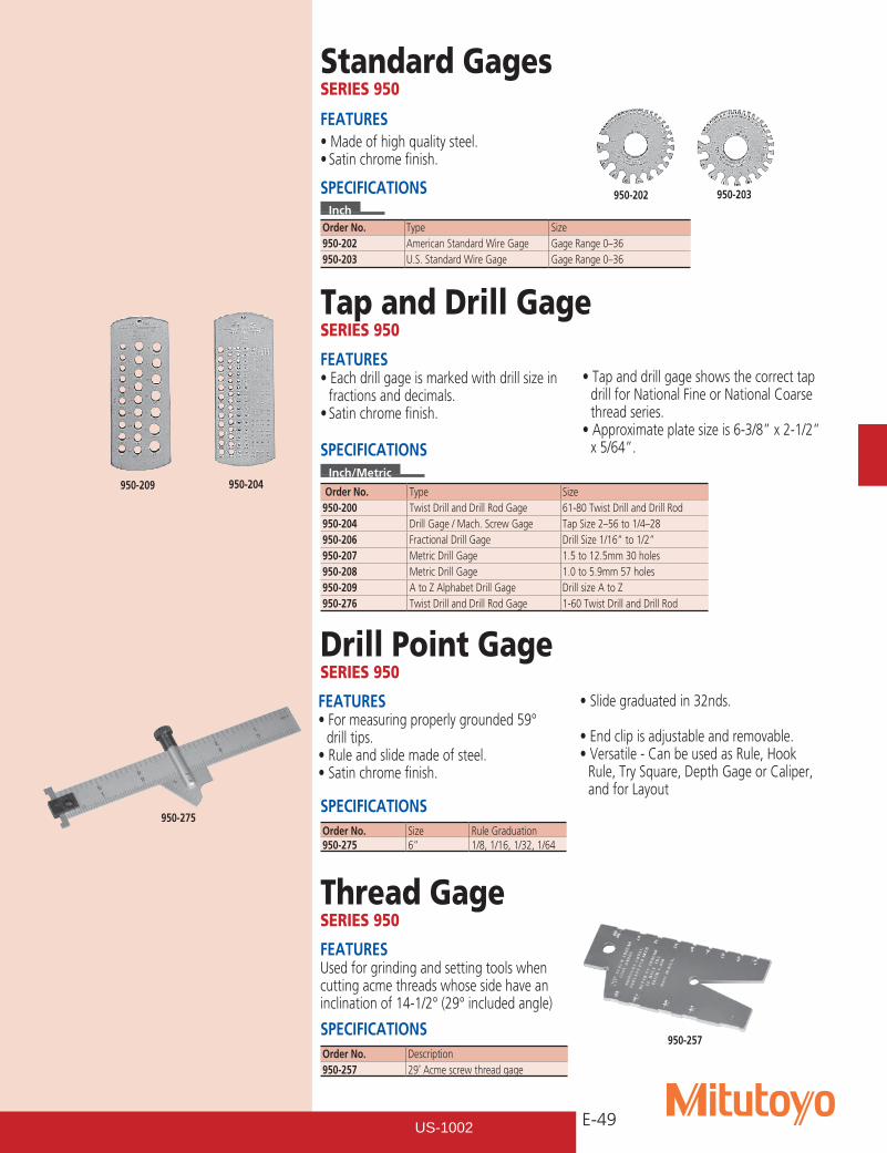
E-49
Standard GagesSERIES 950
FEATURES•Eachdrillgageismarkedwithdrillsizein
fractions and decimals.•Satinchromefinish.
•Tapanddrillgageshowsthecorrecttapdrill for National Fine or National Coarse thread series.•Approximateplatesizeis6-3/8”x2-1/2”
x 5/64”.
SPECIFICATIONS
950-257
950-275
950-209
950-202
Order No. Type Size950-202 American Standard Wire Gage Gage Range 0–36950-203 U.S. Standard Wire Gage Gage Range 0–36
SPECIFICATIONSInch
950-203
Tap and Drill GageSERIES 950
SPECIFICATIONSInch/Metric
Order No. Type Size950-200 Twist Drill and Drill Rod Gage 61-80 Twist Drill and Drill Rod950-204 Drill Gage / Mach. Screw Gage Tap Size 2–56 to 1/4–28950-206 Fractional Drill Gage Drill Size 1/16” to 1/2”950-207 Metric Drill Gage 1.5 to 12.5mm 30 holes950-208 Metric Drill Gage 1.0 to 5.9mm 57 holes950-209 A to Z Alphabet Drill Gage Drill size A to Z950-276 Twist Drill and Drill Rod Gage 1-60 Twist Drill and Drill Rod
950-204
FEATURES•Formeasuringproperlygrounded59°
drill tips.•Ruleandslidemadeofsteel.•Satinchromefinish.
•Slidegraduatedin32nds.
•Endclipisadjustableandremovable.•Versatile-CanbeusedasRule,Hook
Rule, Try Square, Depth Gage or Caliper, and for Layout
Drill Point GageSERIES 950
FEATURESUsed for grinding and setting tools when cutting acme threads whose side have an inclination of 14-1/2° (29° included angle)
Thread GageSERIES 950
SPECIFICATIONS
Order No. Size Rule Graduation950-275 6” 1/8, 1/16, 1/32, 1/64
Order No. Description950-257 29˚ Acme screw thread gage
FEATURES•Madeofhighqualitysteel.•Satinchromefinish.
US-1002
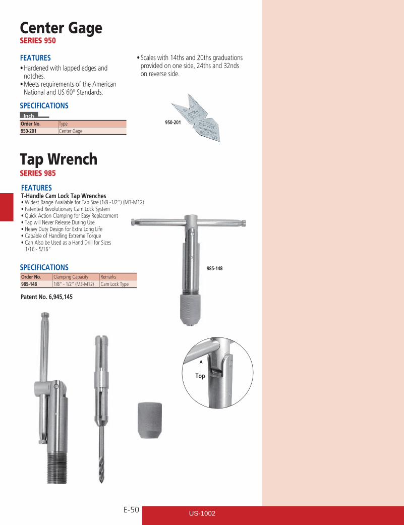
E-50
Center GageSERIES 950
Order No. Type950-201 Center Gage
SPECIFICATIONSInch
FEATURES•Hardenedwithlappededgesand
notches.•MeetsrequirementsoftheAmerican
National and US 60° Standards.
•Scaleswith14thsand20thsgraduationsprovided on one side, 24ths and 32nds on reverse side.
950-201
Tap WrenchSERIES 985
SPECIFICATIONS
FEATUREST-Handle Cam Lock Tap Wrenches•WidestRangeAvailableforTapSize(1/8-1/2”)(M3-M12)•PatentedRevolutionaryCamLockSystem•QuickActionClampingforEasyReplacement•TapwillNeverReleaseDuringUse•HeavyDutyDesignforExtraLongLife•CapableofHandlingExtremeTorque•CanAlsobeUsedasaHandDrillforSizes 1/16 - 5/16”
985-148
Order No. Clamping Capacity Remarks985-148 1/8” - 1/2” (M3-M12) Cam Lock Type
Patent No. 6,945,145
Top
US-1002
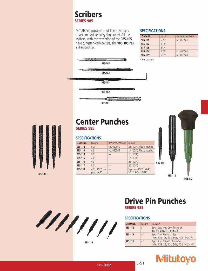
E-51
ScribersSERIES 985
SPECIFICATIONSMITUTOYO provides a full line of scribers to accommodate every shop need. All the scribers, with the exception of the 985-105, have tungsten-carbide tips. The 985-105 has a diamond tip.
Order No. Length Replacement Point985-101 6.75” No. 050561985-102 6.12” —985-103 8.87” —985-104* 5.75” No. 050562985-105* 5.12” No. 050563
985-105
985-104
985-103
985-102
985-101
Center PunchesSERIES 985
SPECIFICATIONSOrder No. Length Replacement Point Remarks985-112 5.25” No. 050565 .68” (DIA), Plastic housing985-113 6.0” No. 050566 1.0” (DIA), Plastic housing985-114 3.0” — .31” (DIA)985-115 4.0” — .39” (DIA)985-116 4.3” — .59” (DIA)985-117 5.0” — .67” (DIA)885-138 4.0”, 1/16” dia.
punch is 3”— 5 pcs set 1/16”. 5/64”,
3/32”, 9/64”, 5/32”
985-114
985-112985-113
Drive Pin PunchesSERIES 985
SPECIFICATIONS
985-119
Order No. Length Remarks985-118 8” 5pcs. Extra long Drive Pin Punch
Set 1/8, 3/16, 1/4, 5/16, 3/8”985-119 4” 8pcs. Drive Pin Punch Set
1/16, 3/32, 1/8, 5/32, 3/16, 7/32, 1/4, 5/16”985-120 4” 8pcs. Brass Drive Pin Punch Set
1/16, 3/32, 1/8, 5/32, 3/16, 7/32, 1/4, 5/16”
* Retractable
985-138
US-1002
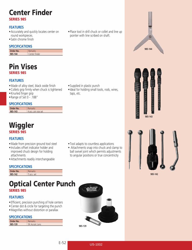
E-52
•Madefromprecisiongroundtoolsteel•Includesoffsetindicatorholderand
improved chuck design for holding attachments•Attachmentsreadilyinterchangeable
•Tooladaptstocountlessapplications•Attachmentssnapintochuckandclampto
ball swivel joint which permits adjustments to angular positions or true concentricity
Center FinderSERIES 985
•Accuratelyandquicklylocatescenteronround workpieces.•Satinchromefinish
•Placetoolindrillchuckorcolletandlineuppointer with line scribed on shaft.
985-144
Pin VisesSERIES 985
SPECIFICATIONSOrder No. Remarks985-144 Center finder
985-143
FEATURES
•Madeofalloysteel,blackoxidefinish•Colletsgripfirmlywhenchuckistightened•Knurledfingergrip•RangeofSet0-.188”
•Suppliedinplasticpunch•Idealforholdingsmalltools,rods,wires,
taps, etc.
FEATURES
WigglerSERIES 985
SPECIFICATIONSOrder No. Remarks985-142 5 pcs. set 985-142
FEATURES
•Efficient,precisionpunchingofholecenters•Centerdot&circlefortargetingthepunch•Magnifieswithoutdistortionorparallax
Optical Center PunchSERIES 985
SPECIFICATIONSOrder No. Remarks985-139 9X Acrylic Lens
985-139
FEATURES
SPECIFICATIONSOrder No. Remarks985-143 4 pcs. pin vise set
US-1002
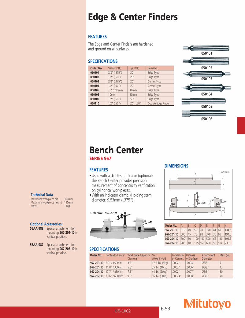
E-53
A
B
C
H
ø25 (25)
DF
G
E
Bench CenterSERIES 967
FEATURES•Usedwithadialtestindicator(optional),
the Bench Center provides precision measurement of concentricity verification on cylindrical workpieces.•Withanindicatorclamp.(Holdingstem
diameter: 9.53mm / .375”)
DIMENSIONS Unit: mm
Order No.: 967-201M
Technical DataMaximum workpiece dia.: 300mmMaximum workpiece height: 150mmMass: 13kg
Order No. A B C D E F G H967-203-10 310 40 50 70 178 41 60 134.5967-201-10 500 45 75 80 370 36 60 194.5967-204-10 700 80 100 140 500 65 110 194.5967-202-10 900 100 125 160 600 50 104 230
SPECIFICATIONSOrder No. Center-to-Center Workpiece Capacity
DiameterMax. Weight Hold
Parallelism of Centers
Flatness of Surface
Attachment Diameter
Mass (kg)
967-203-10 5.9” / 150mm 3.8” 17.5 lbs. (8kg) .0002” .0004” Ø3/8” 7967-201-10 11.8” / 300mm 5.8” 35 lbs. (16kg) .0002” .0006” Ø3/8” 13967-204-10 17.7” / 450mm 7.8” 44 lbs. (20kg) .0002” .0007” Ø3/8” 60967-202-10 23.6” / 600mm 9.8” 66 lbs. (30kg) .00024” .0008” Ø3/8” 70
Optional Accessories:56AAJ988 Special attachment for mounting 967-201-10 in vertical position.
56AAJ987 Special attachment for mounting 967-203-10 in vertical position.
Edge & Center Finders
SPECIFICATIONS
The Edge and Center Finders are hardened and ground on all surfaces.
FEATURES
Order No. Shank (DIA) Tip (DIA) Remarks050101 3/8” (.375”) .20” Edge Type050102 1/2” (.50”) .20” Edge Type050103 3/8” (.375”) .20” Center Type050104 1/2” (.50”) .20” Center Type050105 .375”/10mm 10mm Edge Type050106 10mm 10mm Edge Type050109 1/2” (.50”) .50” Edge Type050110 1/2” (.50”) .20”, .50” Double Edge Finder
050101
050102
050103
050104
050105
050106
US-1002
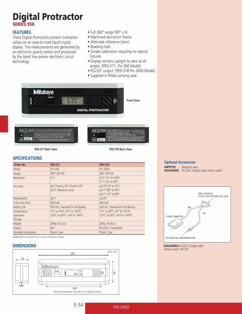
E-54
FEATURESThese Digital Protractors present inclination values on an easy-to-read liquid crystal display. The measurements are generated by an electronic gravity sensor and processed by the latest low-power electronic circuit technology.
•Full360°range(90°x4).•Machinedaluminumframe.•Alternatereference(zero).•Readinghold.•Simplecalibrationrequiringnospecial
fixtures.•Displayremainsuprighttoviewatall
angles. (950-317, Pro 360 Model).•RS232Coutput.(950-318Pro3600Model).•Suppliedinfittedcarryingcase.
Optional Accessories64PPP795 Magnetic base50AAA983A RS-232C Output cable w/foot switch
ON
/OFF HOLD HOLD
ALTZERO
ALT
ZER
O
153
31
140°105
490.0°
Digital ProtractorSERIES 950
SPECIFICATIONS
DIMENSIONSUnit: mm
Front View
Order No. 950-317 950-318Model Pro 360 Pro 3600Range 360° (90°x4) 360° (90°x4)Resolution 0.1° 0.01° (0° to 9.99°)
0.1° (10° to 90°)Accuracy ±0.1°Level ±10°, Plumb ±10°
±0.2° Maximum error±0.05° (0° to 10°)±0.1° (80° to 90°)±0.2° (10° to 80°)
Repeatability ±0.1° ±0.05°Cross Axis Error Minimal MinimalBattery Life 500 Hrs. Standard 9-Volt Battery 500 Hrs. Standard 9-Volt BatteryTemperatureOperationStorage
-5°C to 50°C (23° to 122°F)-20°C to 65°C (-4°F to 149°F)
-5°C to 50°C (23° to 122°F)-20°C to 65°C (-4°F to 149°F)
Weight 289g (10.2oz.) 295g (10.4oz.)Output N/A RS-232C CompatibleStandard Accessories Plastic Case Plastic Case±Represents clockwise or counter-clockwise slope.
DB9, FEMALETO PC OR INTERFACE UNIT
TO DIGITAL PROTRACTOR
FOOT SWITCH
2m
2m
50AAA983A RS-232C Output cable w/foot switch 10P-25P
(Distance between two M3 x 0.5 tapped holes)
950-317 Back View 950-318 Back View
US-1002
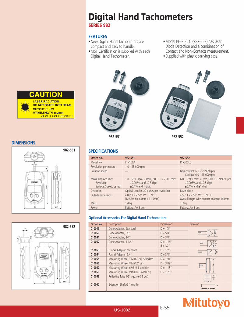
E-55
Digital Hand TachometersSERIES 982
SPECIFICATIONSOrder No. 982-551 982-552Model No. PH-100A PH-200LCRevolution per minute 1.0 – 25,000 rpm —Rotation speed — Non-contact: 6.0 – 99,999 rpm;
Contact: 6.0 – 25,000 rpmMeasuring accuracy
Revolution Surface, Speed, Length
1.0 – 599.9rpm: ±1rpm, 600.0 – 25,000 rpm: ±0.006% and ±0.5 digit ±0.4% and 1 digit
6.0 – 599.9 rpm: ±1rpm, 600.0 – 99,999 rpm ±0.006% and ±0.5 digit ±0.4% and ±1 digit
Detection Optical coupler, 20 pulses per revolution Laser diodeOutside dimensions 4.83” L x 2.52” W x 1.24” H
(122.5mm x 64mm x 31.5mm) 4.55” L x 2.52” W x 1.24” H Overall length with contact adapter: 149mm
Mass 170 g 160 gPower Battery: AA 3 pcs. Battery: AA 3 pcs.
Optional Accessories For Digital Hand Tachometers
Order No. Description Dimension Drawing010049 Cone Adapter, Standard D = 1/2”010050 Cone Adapter, 5/8” D = 5/8”010051 Cone Adapter, 3/4” D = 3/4”010052 Cone Adapter, 1-1/4” D = 1-1/4”
d = 1/2”010053 Funnel Adapter, Standard D = 1/2”010054 Funnel Adapter, 3/4” D = 3/4”010055 Measuring Wheel FPM (6” cir), Standard D = 1.91”010056 Measuring Wheel FPM (12” cir) D = 3.82”010057 Measuring Wheel YPM (0.1 yard cir) D = 1.15”010058 Measuring Wheel MPM (0.1 meter cir) D = 1.25”010059 Reflective Tabs 1/2” square (35 pcs)
010060 Extension Shaft (3” length)
982-551 982-552
FEATURES•NewDigitalHandTachometersare
compact and easy to handle.•NISTCertificationissuppliedwitheach
Digital Hand Tachometer.
•ModelPH-200LC(982-552)haslaserDiode Detection and a combination of Contact and Non-Contacts measurement.•Suppliedwithplasticcarryingcase.
DIMENSIONS982-551
982-552
US-1002
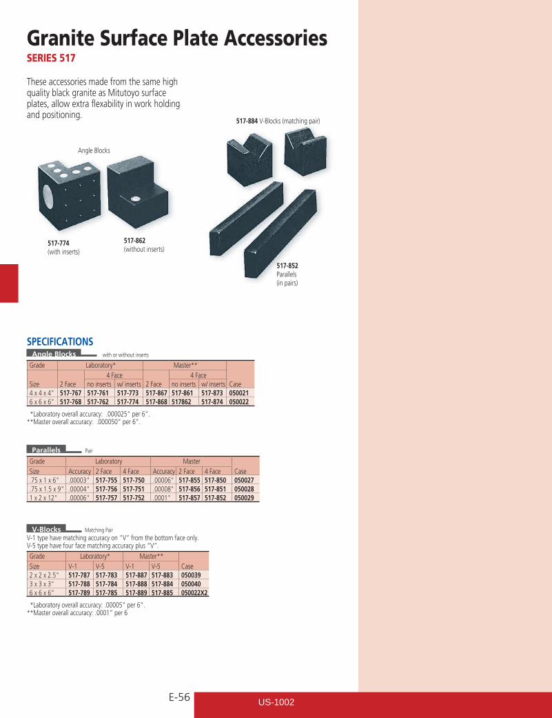
E-56
Granite Surface Plate AccessoriesSERIES 517
SPECIFICATIONSAngle Blocks
Grade Laboratory* Master**4 Face 4 Face
Size 2 Face no inserts w/ inserts 2 Face no inserts w/ inserts Case4x4x4" 517-767 517-761 517-773 517-867 517-861 517-873 0500216x6x6" 517-768 517-762 517-774 517-868 517862 517-874 050022
*Laboratory overall accuracy: .000025” per 6”.**Master overall accuracy: .000050” per 6”.
517-774(with inserts)
517-862(without inserts)
517-852Parallels(in pairs)
517-884 V-Blocks (matching pair)
Angle Blocks
These accessories made from the same high quality black granite as Mitutoyo surface plates, allow extra flexability in work holding and positioning.
Parallels
Grade Laboratory MasterSize Accuracy 2 Face 4 Face Accuracy 2 Face 4 Face Case.75x1x6" .00003" 517-755 517-750 .00006" 517-855 517-850 050027.75x1.5x9" .00004" 517-756 517-751 .00008" 517-856 517-851 0500281x2x12" .00006" 517-757 517-752 .0001" 517-857 517-852 050029
V-BlocksV-1 type have matching accuracy on “V” from the bottom face only.V-5 type have four face matching accuracy plus “V”.
Grade Laboratory* Master**Size V-1 V-5 V-1 V-5 Case2x2x2.5" 517-787 517-783 517-887 517-883 0500393x3x3" 517-788 517-784 517-888 517-884 0500406x6x6" 517-789 517-785 517-889 517-885 050022X2
*Laboratory overall accuracy: .00005” per 6”.**Master overall accuracy: .0001” per 6
Matching Pair
Pair
with or without inserts
US-1002
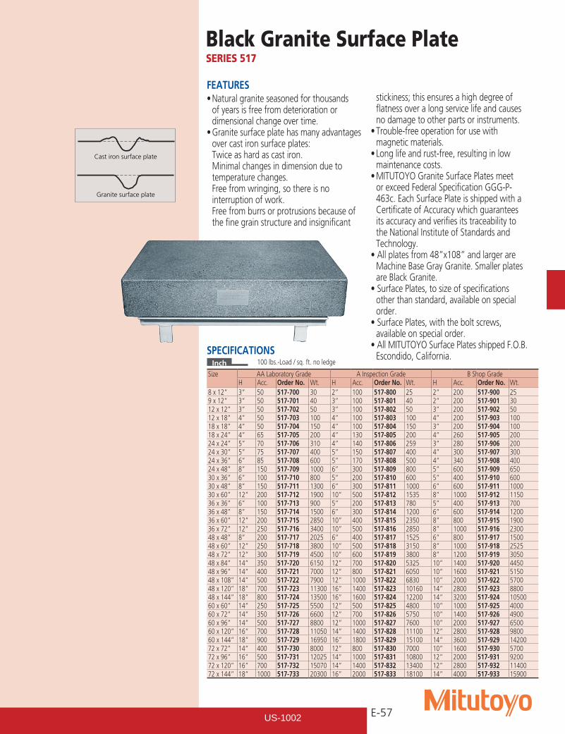
E-57
Cast iron surface plate
Granite surface plate
Black Granite Surface PlateSERIES 517
FEATURES•Naturalgraniteseasonedforthousands
of years is free from deterioration or dimensional change over time.•Granitesurfaceplatehasmanyadvantages
over cast iron surface plates: Twice as hard as cast iron. Minimal changes in dimension due to
temperature changes. Free from wringing, so there is no
interruption of work. Free from burrs or protrusions because of
the fine grain structure and insignificant
stickiness; this ensures a high degree of flatness over a long service life and causes no damage to other parts or instruments.•Trouble-freeoperationforusewith
magnetic materials.•Longlifeandrust-free,resultinginlow
maintenance costs.•MITUTOYOGraniteSurfacePlatesmeet
or exceed Federal Specification GGG-P-463c. Each Surface Plate is shipped with a Certificate of Accuracy which guarantees its accuracy and verifies its traceability to the National Institute of Standards and Technology.•Allplatesfrom48”x108”andlargerare
Machine Base Gray Granite. Smaller plates are Black Granite.•SurfacePlates,tosizeofspecifications
other than standard, available on special order.•SurfacePlates,withtheboltscrews,
available on special order.•AllMITUTOYOSurfacePlatesshippedF.O.B.
Escondido, California.SPECIFICATIONSInch
Size AA Laboratory Grade A Inspection Grade B Shop GradeH Acc. Order No. Wt. H Acc. Order No. Wt. H Acc. Order No. Wt.
8 x 12” 3” 50 517-700 30 2” 100 517-800 25 2” 200 517-900 259 x 12” 3” 50 517-701 40 3” 100 517-801 40 2” 200 517-901 3012 x 12” 3” 50 517-702 50 3” 100 517-802 50 3” 200 517-902 5012 x 18” 4” 50 517-703 100 4” 100 517-803 100 4” 200 517-903 10018 x 18” 4” 50 517-704 150 4” 100 517-804 150 3” 200 517-904 10018 x 24” 4” 65 517-705 200 4” 130 517-805 200 4” 260 517-905 20024 x 24” 5” 70 517-706 310 4” 140 517-806 259 3” 280 517-906 20024 x 30” 5” 75 517-707 400 5” 150 517-807 400 4” 300 517-907 30024 x 36” 6” 85 517-708 600 5” 170 517-808 500 4” 340 517-908 40024 x 48” 8” 150 517-709 1000 6” 300 517-809 800 5” 600 517-909 65030 x 36” 6” 100 517-710 800 5” 200 517-810 600 5” 400 517-910 60030 x 48” 8” 150 517-711 1300 6” 300 517-811 1000 6” 600 517-911 100030 x 60” 12” 200 517-712 1900 10” 500 517-812 1535 8” 1000 517-912 115036 x 36” 6” 100 517-713 900 5” 200 517-813 780 5” 400 517-913 70036 x 48” 8” 150 517-714 1500 6” 300 517-814 1200 6” 600 517-914 120036 x 60” 12” 200 517-715 2850 10” 400 517-815 2350 8” 800 517-915 190036 x 72” 12” 250 517-716 3400 10” 500 517-816 2850 8” 1000 517-916 230048 x 48” 8” 200 517-717 2025 6” 400 517-817 1525 6” 800 517-917 150048 x 60” 12” 250 517-718 3800 10” 500 517-818 3150 8” 1000 517-918 252548 x 72” 12” 300 517-719 4500 10” 600 517-819 3800 8” 1200 517-919 305048 x 84” 14” 350 517-720 6150 12” 700 517-820 5325 10” 1400 517-920 445048 x 96” 14” 400 517-721 7000 12” 800 517-821 6050 10” 1600 517-921 515048 x 108” 14” 500 517-722 7900 12” 1000 517-822 6830 10” 2000 517-922 570048 x 120” 18” 700 517-723 11300 16” 1400 517-823 10160 14” 2800 517-923 880048 x 144” 18” 800 517-724 13500 16” 1600 517-824 12200 14” 3200 517-924 1050060 x 60” 14” 250 517-725 5500 12” 500 517-825 4800 10” 1000 517-925 400060 x 72” 14” 350 517-726 6600 12” 700 517-826 5750 10” 1400 517-926 490060 x 96” 14” 500 517-727 8800 12” 1000 517-827 7600 10” 2000 517-927 650060 x 120” 16” 700 517-728 11050 14” 1400 517-828 11100 12” 2800 517-928 980060 x 144” 18” 900 517-729 16950 16” 1800 517-829 15100 14” 3600 517-929 1420072 x 72” 14” 400 517-730 8000 12” 800 517-830 7000 10” 1600 517-930 570072 x 96” 16” 500 517-731 12025 14” 1000 517-831 10800 12” 2000 517-931 920072 x 120” 16” 700 517-732 15070 14” 1400 517-832 13400 12” 2800 517-932 1140072 x 144” 18” 1000 517-733 20300 16” 2000 517-833 18100 14” 4000 517-933 15900
100 lbs.-Load / sq. ft. no ledge
US-1002
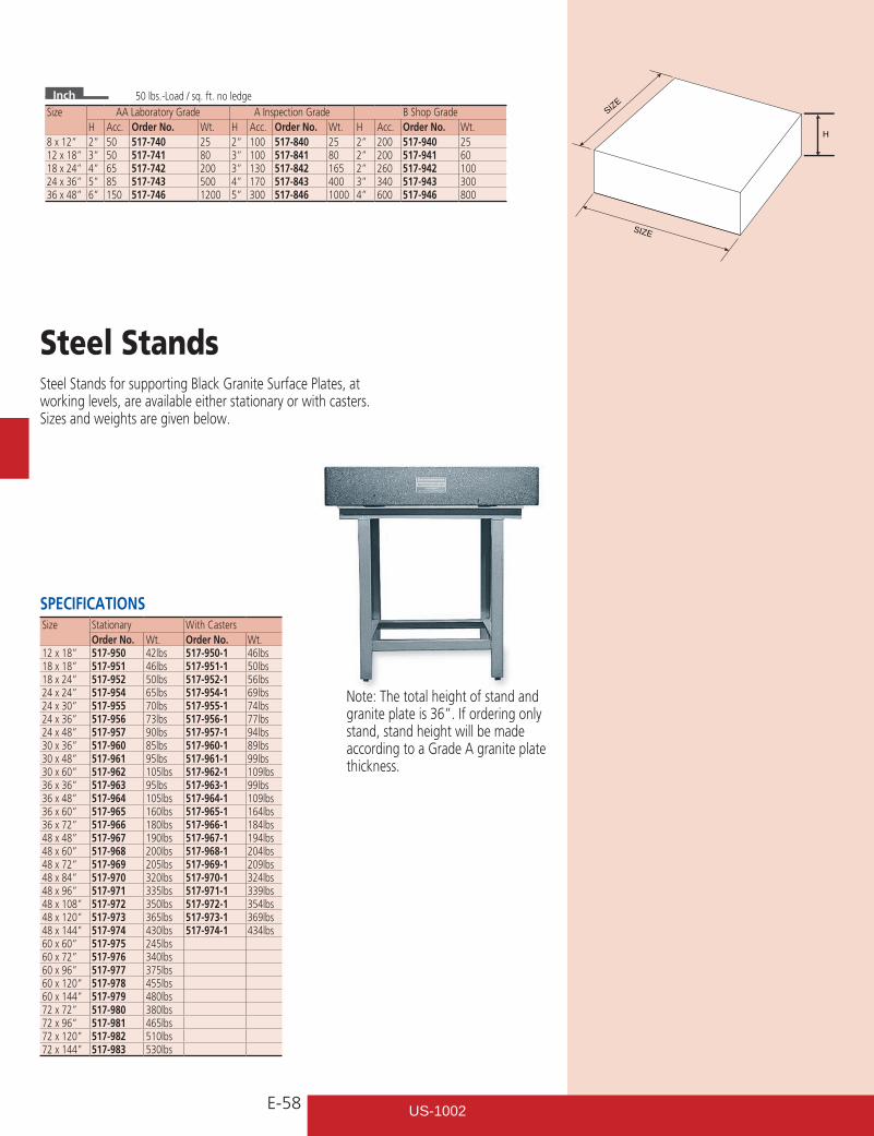
E-58
SIZE
SIZE
H
Note: The total height of stand and granite plate is 36”. If ordering only stand, stand height will be made according to a Grade A granite plate thickness.
Steel Stands for supporting Black Granite Surface Plates, at working levels, are available either stationary or with casters. Sizes and weights are given below.
Inch
Size AA Laboratory Grade A Inspection Grade B Shop GradeH Acc. Order No. Wt. H Acc. Order No. Wt. H Acc. Order No. Wt.
8 x 12” 2” 50 517-740 25 2” 100 517-840 25 2” 200 517-940 2512 x 18” 3” 50 517-741 80 3” 100 517-841 80 2” 200 517-941 6018 x 24” 4” 65 517-742 200 3” 130 517-842 165 2” 260 517-942 10024 x 36” 5” 85 517-743 500 4” 170 517-843 400 3” 340 517-943 30036 x 48” 6” 150 517-746 1200 5” 300 517-846 1000 4” 600 517-946 800
50 lbs.-Load / sq. ft. no ledge
Size Stationary With CastersOrder No. Wt. Order No. Wt.
12 x 18” 517-950 42lbs 517-950-1 46lbs18 x 18” 517-951 46lbs 517-951-1 50lbs18 x 24” 517-952 50lbs 517-952-1 56lbs24 x 24” 517-954 65lbs 517-954-1 69lbs24 x 30” 517-955 70lbs 517-955-1 74lbs24 x 36” 517-956 73lbs 517-956-1 77lbs24 x 48” 517-957 90lbs 517-957-1 94lbs30 x 36” 517-960 85lbs 517-960-1 89lbs30 x 48” 517-961 95lbs 517-961-1 99lbs30 x 60” 517-962 105lbs 517-962-1 109lbs36 x 36” 517-963 95lbs 517-963-1 99lbs36 x 48” 517-964 105lbs 517-964-1 109lbs36 x 60” 517-965 160lbs 517-965-1 164lbs36 x 72” 517-966 180lbs 517-966-1 184lbs48 x 48” 517-967 190lbs 517-967-1 194lbs48 x 60” 517-968 200lbs 517-968-1 204lbs48 x 72” 517-969 205lbs 517-969-1 209lbs 48 x 84” 517-970 320lbs 517-970-1 324lbs48 x 96” 517-971 335lbs 517-971-1 339lbs48 x 108” 517-972 350lbs 517-972-1 354lbs48 x 120” 517-973 365lbs 517-973-1 369lbs48 x 144” 517-974 430lbs 517-974-1 434lbs60 x 60” 517-975 245lbs60 x 72” 517-976 340lbs60 x 96” 517-977 375lbs60 x 120” 517-978 455lbs60 x 144” 517-979 480lbs 72 x 72” 517-980 380lbs72 x 96” 517-981 465lbs72 x 120” 517-982 510lbs72 x 144” 517-983 530lbs
Steel Stands
SPECIFICATIONS
US-1002