index of contents - insevis · index of contents general instructions ... (alarms and events) ......
TRANSCRIPT

Index of contentsGeneral instructions .......................................................................................................................................................................... 7About INSEVIS ................................................................................................................................................................................. 8Product family Software .................................................................................................................................................................... 9Configuration with the Software „ConfigStage“ ............................................................................................................................... 11
Basic settings ............................................................................................................................................................................ 11Assign the IP-address ......................................................................................................................................................... 12Change target device .......................................................................................................................................................... 12
Addressing of the onboard periphery ........................................................................................................................................ 12Standard addressing ind the INSEVIS- PLCs ..................................................................................................................... 12Different addressing in PLCs and addressing of decentral periphery ................................................................................. 12
CPU settings ............................................................................................................................................................................. 13Communication settings ............................................................................................................................................................ 15
RS232 and RS485 .............................................................................................................................................................. 15Ethernet ............................................................................................................................................................................... 15
CAN configuration ..................................................................................................................................................................... 17Decentral INSEVIS periphery .............................................................................................................................................. 17Configure decentral external periphery manually ................................................................................................................ 18Create library elements of your CAN-slaves ....................................................................................................................... 19Configure decentral external peripherie by EDS-file ........................................................................................................... 20Decentral external periphery / motion controller pre defined .............................................................................................. 21Samples for external CANopen devices ............................................................................................................................. 22
Visualization with the software „VisuStage“ .................................................................................................................................... 24Download and licensing ............................................................................................................................................................ 24System functions ....................................................................................................................................................................... 24Communication between PLC and external Panel-HMI ........................................................................................................... 24General settings of the program shell ....................................................................................................................................... 25
General functionality ........................................................................................................................................................... 26Recommended procedures ................................................................................................................................................. 26Save your resources .......................................................................................................................................................... 26Keep the overview ............................................................................................................................................................... 26Transfer your work to other projects .................................................................................................................................... 26
Project settings ......................................................................................................................................................................... 27Version counter ................................................................................................................................................................... 27Assign the target IP-address ............................................................................................................................................... 27File formats ......................................................................................................................................................................... 27Data protection at binary upload ......................................................................................................................................... 27VNC-Server (CPU-T devices only) ...................................................................................................................................... 27Configure a VNC-Viewer/-Client .......................................................................................................................................... 28Change screen orientation or resolution ............................................................................................................................. 29
Create and administrate resources ........................................................................................................................................... 29Resource languages ........................................................................................................................................................... 29Resource variables ............................................................................................................................................................. 30
Multiplex-variables ......................................................................................................................................................... 35Resources Texts and Text lists ............................................................................................................................................ 36Resources Images and Image lists ..................................................................................................................................... 38Resource Messages (Alarms and Events) .......................................................................................................................... 40Resource User administration ............................................................................................................................................. 41
Change user level by SFC215 "LOGIN" ........................................................................................................................ 42Resource Partner-PLC (for HMI only) ................................................................................................................................. 43
Partner-PLC Synchronization (for HMI only) ................................................................................................................. 43Resource Dialogs ................................................................................................................................................................ 44Resource Screen templates ................................................................................................................................................ 44Resources Trends ............................................................................................................................................................... 45
Starting the trend sampling with SFC 202 "TRENDSRT" .............................................................................................. 46Stopping the trend sampling with SFC 203 "TRENDSTP" ............................................................................................ 48Continue the trend sampling with SFC 204 "TRENDCNT" ............................................................................................ 49Query the trend status with SFC 205 "TRENDSTA" ..................................................................................................... 50
Resource recipe administration and recipe viewer ............................................................................................................. 52Recipe handling with SFC 206 "RECIPE" .................................................................................................................... 54
Basic functions .................................................................................................................................................................... 56Screens ............................................................................................................................................................................... 56
Query the current the screen ID number with SFC 200 "SCR_GET" ............................................................................ 59Changing the screen with SFC 201 "SCR_SET" ........................................................................................................... 60
Creating a visualization screen ................................................................................................................................................. 61Static objects ....................................................................................................................................................................... 61
Lines, rectangles, texts, images .................................................................................................................................... 61Images ........................................................................................................................................................................... 61
2 INSEVIS Gesellschaft für industrielle Systemelektronik und Visualisierung mbH • Am Weichselgarten 7 • D-91058 ErlangenManual Software, Rev. 02 / 2018

Dynamic objects .................................................................................................................................................................. 62Date/Time fields ............................................................................................................................................................. 62I/O fields ........................................................................................................................................................................ 63PIN input fields .............................................................................................................................................................. 64Diverse kinds of buttons ................................................................................................................................................ 65Touch areas – invisible buttons ..................................................................................................................................... 67State areas ................................................................................................................................................................... 68Radio boxes and Check boxes ...................................................................................................................................... 69Progress bars ................................................................................................................................................................ 70Sliders ............................................................................................................................................................................ 71System data (IP-address field, languages, etc.) ............................................................................................................ 72Gauges .......................................................................................................................................................................... 73
Viewers ................................................................................................................................................................................ 75Image and text lists ........................................................................................................................................................ 75Message viewing and archiving ..................................................................................................................................... 76Trend viewer and trend archive viewer .......................................................................................................................... 78Recipe viewer ................................................................................................................................................................ 80Function graph ............................................................................................................................................................... 83
Working with library elements ................................................................................................................................................... 85Creating libraries and ~ elements ....................................................................................................................................... 85Using library elements ......................................................................................................................................................... 85
Simulation and download .......................................................................................................................................................... 86Error treatment .................................................................................................................................................................... 86Simulation and download .................................................................................................................................................... 87
Remote access with the software „RemoteStage“ ......................................................................................................................... 89General ..................................................................................................................................................................................... 89
Selection of the remote-device ............................................................................................................................................ 89Using and setting up the remote screen ............................................................................................................................ 90Storing the remote (on the PC) archived data ..................................................................................................................... 90Converting archive data into csv-files ................................................................................................................................. 90Recipe import, display, converting, editing and export ........................................................................................................ 92Data (DB) archive upload, display, storing and download ................................................................................................... 93
Command line of RemoteStage (Viewing mode) ...................................................................................................................... 94Automatic connecting to remote panel after starting PC ..................................................................................................... 94Automatic full screen after starting PC ................................................................................................................................ 94Set up TCP port number for S7-communication ................................................................................................................. 94
Command line of RemoteStage (Archive mode) ...................................................................................................................... 95Read in (upload) message- and trend archives from remote device .................................................................................. 95Read in (upload) recipe archive from remote device .......................................................................................................... 96Write back (download) recipe archive into remote device ................................................................................................... 97Read in (upload) data (DB-) archive from remote device .................................................................................................... 98Write back (download) data (DB-) archive into remote device ............................................................................................ 98Return codes ....................................................................................................................................................................... 99
Working with the software „ServiceStage“ .................................................................................................................................... 100Function overview ................................................................................................................................................................... 100
General information ........................................................................................................................................................... 100Operating mode ................................................................................................................................................................ 100Date and time .................................................................................................................................................................... 100Memory ............................................................................................................................................................................. 101Diagnostic buffer ............................................................................................................................................................... 101Know-how-protection ........................................................................................................................................................ 101Block Update ..................................................................................................................................................................... 102Online Backup ................................................................................................................................................................... 103
INSEVIS Gesellschaft für industrielle Systemelektronik und Visualisierung mbH • Am Weichselgarten 7 • D-91058 Erlangen 3Manual Software, Rev. 02 / 2018

Changes to older versions of the manual
Rev. 02 / 2012:new: chapter Recipe administration and recipe viewer in VisuStage
chapter Remote acces with software „RemoteStage“chapter Screens with backlightcontrol, clean screen, etc in VisuStage
Rev. 03 / 2012:changed: chapters „ConfigStage“, „RemoteStage“ and „VisuStage“ completely rebuilt and referred to demo visu 2012_04
Rev. 04 / 2012:changed: chapters „VisuStage“ new functionls like color/text switching buttons, limited I/O-fields, etc.,
from VisuStage 2.0.2.4 referred to demo visu 2012_04_1
Rev. 05 / 2012:changed: ConfigStage:explenation of cycling time added (CPU settings), RemoteStage with „Read-In-by-Ethernet“-
functionality, VisuStage: improvements at receipt administration and objects placing(from VisuStage 2.0.1.5 referred to demo visu 2012_04_2, from PLC-OS 2.0.33)
Rev. 01 / 2013:new: Assigning an IP-adress with ConfigStage 1.0.14.5 and PLC-firmware (operating system/OS) 2.0.35
Rev. 02 / 2013:new: ServiceStage added
Rev. 03 / 2013:new: VisuStage V2.0.2.0 described, buzzer added, chapter VisuStage completely reworked
(now referred to new demo visu 2013_01, from PLC-OS 2.0.37)
Rev. 04 / 2013:new: VisuStage V2.0.2.2 and RemoteStage 1.0.3.3 new features (with PLC-OS 2.0.38, HMI-OS 1.0.5), text buttons
and watchdog added, now referred to new demo visu 2013_02
Rev. 05 / 2013:new: New description for VisuStage 2.0.2.3 / RemoteStage 1.0.3.4 (PLC-OS 2.0.39, HMI-OS 1.0.7) with
colour change at Texts, confirmation messages at receipes, sorting at message archive, adjustable font sizesand scales in progress bars and trend archives, new download mechanism, I/O-fields with integer-input withcomma, now referred to new demo visu 2013_04
Rev. 06 / 2013:new: New description for ConfigStage: PDO-/ SDO-Mapping, address overview list (from ConfigStage 1.0.14.7)
description for VisuStage: Use of SFC201-5 from PLC with seperated Panel-HMI(with PLS-OS 2.0.40 and HMI-OS 1.0.9)
Rev. 07 / 2013:new: New remote-functions; recipe records: read out/ store, (DB-) archiving: read out/ store
Read in visualization binary over Ethernet directly from Panel (with RemoteStage V1.0.3.7)New PLC-function: SFC206: read/ write recipe record into PLC with S7, SFC207: archiving DBs(with PLC-OS 2.0.41 and HMI-OS 1.0.11)
Rev. 08 / 2013:new: Service Stage 1.0.1.1: Know-how-protection availabe, ConfigStage 1.14.9 with EDS-Import,
(with PLC-firmware 2.1.0 and S7-Lib 2_1_0 and with HMI-firmware 1.1.0)
Rev. 09 / 2013:new: VisuStage 2.0.3.1: library management, group/ungroup function, RemoteStage 1.0.4.0: PIN-code request at
visualization-binary import valid from PLC-firmware 2.1.1 and HMI-Firmware 1.1.1
Rev. 10 / 2013:new: VisuStage 2.0.3.4 / RemoteStage 1.0.4.2: Rotation of screens possible, Filtering of variables,
Additional display of trigger-and acknowledgement variables at alarm/event ressorces, from PLC-firmware 2.1.3 and HMI-firmware 1.1.3
Rev. 11 / 2013:new: VisuStage 2.0.3.5: „Cross Reference“-function and display of list resources at image/text lists.
ConfigStage 1.0.14.10 „Change device“ function added
Rev. 01 / 2014:new: VisuStage 2.0.3.6 and RemoteStage 1.0.4.3 : Grid/Snap, Screen template/Master foil, function „Screen change
with PIN-input“, I/O-Fields: Input in calculator-style (with „comma“-key) insertedfrom PLC-firmware 2.1.4, HMI-firmware 1.1.4
Rev. 02 / 2014:new: VisuStage 2.0.3.9 and RemoteStage 1.0.4.5 : new: Function graph, added: buttondesign @ virtual keyboards
from PLC-firmware 2.1.5 and HMI-firmware 1.1.5changed: Structure in chapter VisuStage improved
4 INSEVIS Gesellschaft für industrielle Systemelektronik und Visualisierung mbH • Am Weichselgarten 7 • D-91058 ErlangenManual Software, Rev. 02 / 2018
Changes to older versions of the manual
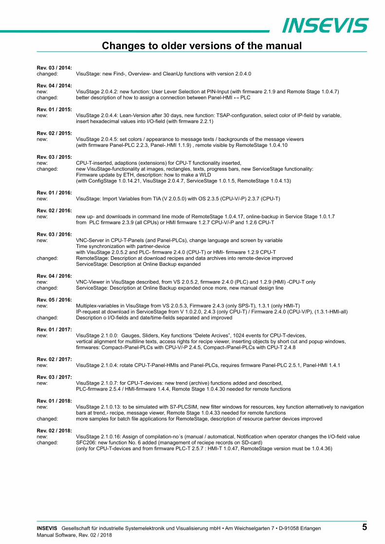
Rev. 03 / 2014:changed: VisuStage: new Find-, Overview- and CleanUp functions with version 2.0.4.0
Rev. 04 / 2014:new: VisuStage 2.0.4.2: new function: User Lever Selection at PIN-Input (with firmware 2.1.9 and Remote Stage 1.0.4.7)changed: better description of how to assign a connection between Panel-HMI ↔ PLC
Rev. 01 / 2015:new: VisuStage 2.0.4.4: Lean-Version after 30 days, new function: TSAP-configuration, select color of IP-field by variable,
insert hexadecimal values into I/O-field (with firmware 2.2.1)
Rev. 02 / 2015:new: VisuStage 2.0.4.5: set colors / appearance to message texts / backgrounds of the message viewers
(with firmware Panel-PLC 2.2.3, Panel-.HMI 1.1.9) , remote visible by RemoteStage 1.0.4.10
Rev. 03 / 2015:new: CPU-T-inserted, adaptions (extensions) for CPU-T functionality inserted, changed: new VisuStage-functionality at images, rectangles, texts, progress bars, new ServiceStage functionality:
Firmware update by ETH, description: how to make a WLD(with ConfigStage 1.0.14.21, VisuStage 2.0.4.7, ServiceStage 1.0.1.5, RemoteStage 1.0.4.13)
Rev. 01 / 2016:new: VisuStage: Import Variables from TIA (V 2.0.5.0) with OS 2.3.5 (CPU-V/-P) 2.3.7 (CPU-T)
Rev. 02 / 2016:new: new up- and downloads in command line mode of RemoteStage 1.0.4.17, online-backup in Service Stage 1.0.1.7
from PLC firmware 2.3.9 (all CPUs) or HMI firmware 1.2.7 CPU-V/-P and 1.2.6 CPU-T
Rev. 03 / 2016:new: VNC-Server in CPU-T-Panels (and Panel-PLCs), change language and screen by variable
Time synchronization with partner-devicewith VisuStage 2.0.5.2 and PLC- firmware 2.4.0 (CPU-T) or HMI- firmware 1.2.9 CPU-T
changed: RemoteStage: Description at download recipes and data archives into remote-device improvedServiceStage: Description at Online Backup expanded
Rev. 04 / 2016:new: VNC-Viewer in VisuStage described, from VS 2.0.5.2, firmware 2.4.0 (PLC) and 1.2.9 (HMI) -CPU-T onlychanged: ServiceStage: Description at Online Backup expanded once more, new manual design line
Rev. 05 / 2016:new: Multiplex-variables in VisuStage from VS 2.0.5.3, Firmware 2.4.3 (only SPS-T), 1.3.1 (only HMI-T)
IP-request at download in ServiceStage from V 1.0.2.0, 2.4.3 (only CPU-T) / Firmware 2.4.0 (CPU-V/P), (1.3.1-HMI-all)changed: Description o I/O-fields and date/time-fields separated and improved
Rev. 01 / 2017:new: VisuStage 2.1.0.0: Gauges, Sliders, Key functions “Delete Arcives”, 1024 events for CPU-T-devices,
vertical alignment for multiline texts, access rights for recipe viewer, inserting objects by short cut and popup windows,firmwares: Compact-/Panel-PLCs with CPU-V/-P 2.4.5, Compact-/Panel-PLCs with CPU-T 2.4.8
Rev. 02 / 2017:new: VisuStage 2.1.0.4: rotate CPU-T-Panel-HMIs and Panel-PLCs, requires firmware Panel-PLC 2.5.1, Panel-HMI 1.4.1
Rev. 03 / 2017:new: VisuStage 2.1.0.7: for CPU-T-devices: new trend (archive) functions added and described,
PLC-firmware 2.5.4 / HMI-firmware 1.4.4, Remote Stage 1.0.4.30 needed for remote functions
Rev. 01 / 2018:new: VisuStage 2.1.0.13: to be simulated with S7-PLCSIM, new filter windows for resources, key function alternatively to navigation
bars at trend,- recipe, message viewer, Remote Stage 1.0.4.33 needed for remote functionschanged: more samples for batch file applications for RemoteStage, description of resource partner devices improved
Rev. 02 / 2018:new: VisuStage 2.1.0.16: Assign of compilation-no´s (manual / automatical, Notification when operator changes the I/O-field valuechanged: SFC206: new function No. 6 added (management of reciepe records on SD-card)
(only for CPU-T-devices and from firmware PLC-T 2.5.7 : HMI-T 1.0.47, RemoteStage version must be 1.0.4.36)
INSEVIS Gesellschaft für industrielle Systemelektronik und Visualisierung mbH • Am Weichselgarten 7 • D-91058 Erlangen 5Manual Software, Rev. 02 / 2018
Hint for better understanding by application videos
In the English YouTube-channel INSEV IS En we supply different playlists with handling videos for single details referring to functions, describedin this manual. This will help you to get familiar with INSVEIS much faster – PLEASE use it beside this manual!
6 INSEVIS Gesellschaft für industrielle Systemelektronik und Visualisierung mbH • Am Weichselgarten 7 • D-91058 ErlangenManual Software, Rev. 02 / 2018

General instructions
Safety instructionsThis manual contains instructions to avoid material damage and must be carefully attended for your own safety.These instructions are identified with a warning triangle with a note of exclamination inside and a signal word (Signalwort) below.
Danger Death, heavy bodily harm or material damage will appear, if appropriated precautions are not taken over.
Warning Death, heavy bodily harm or material damage will appear, if appropriated precautions are not taken over.
Caution Bodily harm or material damage will appear, if appropriated precautions are not taken over.
Attention means, that a unwished results or states can occur, if the appropriated instruction is not noticed.
Important means the commitment to a special behavior or operation for the safe treatment of the controller / machine.
Qualified personnelAll devices described in this manual may only be used, built up and operated together with this documentation. Installation, initiation and operation of these devices might only be done by instructed personnel with certified skills, who can prove their ability to install and initiate electrical and mechanical devices, systems and current circuits in a generally accepted and admitted standard.
Operation according to regulationsThis device might be only used for this operation written in this manual and only in combination with othercertified external devices. For a correct operation a proper transportation, storage, initiation and maintenance isnecessary. All valid safety instructions and regulations for the prevent of industrial accidents are to be attended carefully.The power supply must be connected to a central ground potential in a starlikely wiring.
MaintenanceModifications / repairs of an INSEVIS device might be done only by special educated and trained personnel ofINSEVIS in an ESD-safe area. Every unauthorized opening might cause damages and will terminate allwarranty claims.
Data securityEach customer is responsible by himself for protecting his IT-environment against illegal external attacks. INSEVIS shall not be held liable for any direct, indirect or consequential damages respect to any claims arising from the possible illegal external access to their PLCs or HMIs by Ethernet. If you are not sure, how to protect your environment ask for help at professional legalIT-companies.
CopyrightThis and all other documentation and software, supplied or hosted on INSEVIS web sites to download are copyrighted. Any duplicating of these data in any way without express approval by INSEVIS GmbH is not permitted. All property and copy rights of theses documentation and software and every copy of it are reserved to INSEVIS GmbH.
Trade MarksINSEVIS refers that all trade marks of particular companies used in own documentation as e.g.- STEP®, SIMATIC® and other as reserved trade mark of Siemens AG.- CANopen® and other as reserved trade mark of CAN in Automation eGand more reserved trade marks are property of the particular owners and are subjected to common protection of trade marks.
DisclaimerAll technical details in this documentation were created by INSEVIS with highest diligence. Anyhow mistakes could not be excluded, so no responsibility is taken by INSEVIS for the complete correctness of this information. This documentation will reviewed regulary and necessary corrections will be done in next version.
With publication of this manual all other versions are no longer valid.
Essential knowledge and experiencesTo understand this documentation basic knowledge and experiences of the automation technology in general and the programming with STEP®7 are essential.
INSEVIS Gesellschaft für industrielle Systemelektronik und Visualisierung mbH • Am Weichselgarten 7 • D-91058 Erlangen 7Manual Software, Rev. 02 / 2018

About INSEVIS
S7-system components for industrial automation technologyThe range of INSEVIS- product families enables an integrated solution and easy to handle for small and medium automation application with latest technology, very high quality level and with additional interfaces like CANopen® and Modbus, to be configured easily.
The easy integration of INSEVIS-products into the S7-world meanwhile is famous and exemplary. Complex communication settings will be assigned easily and intuitively, so that these properties expand the common S7-world by far. A large and multilingual visualization in a modern design is done by a few clicks and the work flow is known by every WinCCflex user. It can be simulated on the visualization PC and is accessible remote.
The S7-CPUs -V and -P are the base of the successfully INSEVIS product families with Profibus DP Master/Slave. With the new S7-CPU-T Panel-PLCs and Compact-PLCs are available with Profinet IO Controller.
Step®7-ProgramabilityINSEVIS-S7-CPUs are programmable by STEP 7® - AWL, KOP, FUP, S7-SCL, S7-Graph from Siemens and in general command-compatible to Siemens-CPU S7-315-2PNDP. Some special INSEVIS-blocks expand the functionality and allow outstanding solutions. The S7-programming will be done by good known tools SIMATIC®-Manager or by TIA-Portal® from Siemens always.
IndependenceINSEVIS-products does not base on Windows or Linux, they have an own firmware. Thereby the hard- and software can be exactly designed fora perfect co-ordination with this firmware and a low power consumption. Booting times of less than 4 seconds and completely no software licenses and a current drain of <100mA @ 24V are the result of these facts.
Get your software rid of licensesINSEVIS stands for a clear and honest license policy, what gives the customer sustainable cost benefits. Because of the ownership of BIOS, firmware and PC-software for visualization, configuration and remote access INSEVIS can offer its products completely without licenses.
Made in GermanyDevelopment, PCB-design and -production, test and mounting of all INSEVIS-products - all this is made in Germany. So every product is a proof for the combination of German engineering and economy and is available with a certification of German origin.
INSEVIS operates a yearly certified quality management system ref. to DIN EN ISO 9001.
All suppliers of INSEVIS obligate to this quality management and contribute to the high quality level of INSEVIS-products.
Already during planning these families one goal was indicated as most important: to design highest quality and ergonomics into all products.
These products were put into comprehensive validation tests before they were produced in selected and certified production lines.
INSEVIS - Made in Germany
8 INSEVIS Gesellschaft für industrielle Systemelektronik und Visualisierung mbH • Am Weichselgarten 7 • D-91058 ErlangenManual Software, Rev. 02 / 2018

Product family Software
Communication tp PLC / HMIINSEVIS-software communicates to the INSEVIS PLC and Panel-HMI by TCP/IP. The software finds network partner automaticelly and can indicate it by a blink test.
External memory cardIf new functions in the S7-program or visualization need an firmware update of PLC/HMI, this can be done by an Micro-SD-card in the standard FAT32-format. Also this card is needed for archiving or updating only, not to run the S7-program. Use this card only for archiving of message data, of data from DBs, of trend data as well as of data of therecipe management and for backup/restore. While updating the PLC-firmware by this card, the S7-data will keptuntouched - as they were before.
Most important properties at a glance
Data archiving Backup & RestoreSave and archive process data to the Micro-SD-card
and read it back to the PLC after updating S7-program.Completely without programming device - by using INSEVIS-SFCs
and SFBs. To satisfy the customers for lots of years.
Save all data easily; user program, process data, visualization and archives - protected by password
as a binary file for using in an equal equipped device, what will proceed with all data from the old PLC
Unlimited languages Free remote accountINSEVIS supports all languages, what are installed on the PC, where the visualization is designed. No limitation of the number
of used languages in the visualization-run-time. Always Unicode16-able. Always be at home in every language of the world.
Use your PC-screen as 2nd panel to display and control yourapplication remote. Import and save archive and recipe data as txt-or csv- files. Do it in a multi-instanceable way in your PC, like in a
master display of a control room.
Trend management Multistructured recipes4 time based trends with 16 channels each can be started,
stopped and continued manually or by variables.Display and archive it as you want it to do.
Or display x;y-value couples from DBs in function graphs
Create up to 64 recipes with up to 256 different variables(elements), what result up to 256 data records per recipe.
Export and import recipes, records and elements via the Micro-SD-card.
Fault indicating system User managementDisplay, indicate and archive up to 1024 alarms and 128 events
in all your project languages, as blinking text line or symbol, as single- or multi-line message viewer and -archive.
Export this data automatically as csv-file to any network drive.
Manage up to 9 user levers by run-time editable PINs. Define user based target screens and
change screens depending on user level. Allow or deny access to „hot keys“ as you want to.
Integrated simulation Import & export functionalityCompile your new visualization, get the detailed, linked failure report
to debug it fast. Simulate your visualization immediately and stimulate variables, alarms and events.
Make your screen shots in jpg-format for your documentation.
Import S7-variables including symbols from your SIMATIC®-Manager.
Export your texts for an external translation as csv-file and read itback into the project.
INSEVIS Gesellschaft für industrielle Systemelektronik und Visualisierung mbH • Am Weichselgarten 7 • D-91058 Erlangen 9Manual Software, Rev. 02 / 2018

Product family Software
Configuration
With the free configuration tool „ConfigStage“ you can config the additional functions of the INSEVIS-CPUsand download it into the PLC. The onboard- or decentral INSEVIS-periphery will be added easily by drag´n dropto the periphery slots. Parameters and address areas will be assigned in a box right below. Also you may assign S7-CPU-parameters like in your programming tools from Siemens (like startup, diagnostic, cycle and clock, retententive memory, etc.). A webserver can be configured at CPU-T-PLCs.With the „ConfigStage“-software can be assigned these interfaces :
• RS232 with free ASCII,• RS485 with free ASCII and Modbus RTU,• Ethernet-connections (active S7-connection-RFC1006, TCP, UDP, Modbus-TCP, INSEVIS-Panel-HMI),• CAN (CANopen® by pre-defined parameters or by imported and mapped EDS-files),
Visualization
Creating modern visualizations by the ergonomic software tool „VisuStage“ is a child´s play now. It imports symbolic variables from SimaticManager or TIA-projects, it exports texts to be translated easily. Exacts error messages help you to debug your project until it can be simulated and downloaded. IN the simulation variables values and messages can be stimulated and simulated visu-images can be copied for documentation. Like a “master foil” there can be created drafts for each application and kept as library items for other projects.
• Program language German or English as well,• Unlimited number of project languages available in full version,
(in free lean version only 1 language)• Alarm- and event messaging system and -archive up to 1024 alarms,• Trend data sampling, displaying and archiving for 4 trends with 16 channels each,• Recipe management system with up to 64 recipes with 256 elements in 256 records,• User management system with 9 layers and password protection,• Screen saver, backlight switch-off function, clean screen and buzzer,• Library with 2D- and 3D-symbols, integrated simulation.• VNC-server for CPU-T-Panel-PLCs
Remote access
With the free-of-charge software „RemoteStage“ there can be made a remote visualization from the binary of a VisuStage-visualization created before. This program is a portable solution but with lots of functions. It communicates via TCP/IP with the Panel-PLC or Panel-HMI and can import the necessary binary from there as well. By using this binary format no one can read back the source code of your visualization.These archive data can be read in from the Micro-SD-card via Ethernet into the PC and stored there.
• 1024 alarm archives and 128 Eventchives (Panel-PLC and Panel-HMI), • 4 trends with up to 16 channels (Panel-PLC and Panel-HMI),• 256 recipe records with up to 256 elements (Panel-PLC and Panel-HMI),• Data (DB) -archives (Panel-PLC and Compact-PLC)This procedure is also possible as command line in any batch process. Multiple RemoteStages can be operated in one PC to get a kind of master display with multiple remote screens.
Service tool
The „ServiceStage“ is made to have easy service access to the PLCs. It allows to identify a S7-CPU by its IP-address and to analyze it by diagnostic buffer, to update the user-programs and to set the protection levels.This software is free of licenses, offers lots of service functions easily to be found even if you are not workingevery day with this software tool. Installed in a minute, useful service functions, absolutely easy to understand and to use. These functions can be solved with the „ServiceStage“
• Device specific data like (ser.-no., firmware version, IP-address (editable), MAC-address, etc.),• Update firmware (CPU-T only),• Changing of the operation mode RUN ↔ STOP, • Set and synchronize date and time,• Memory diagnostic and comprimation,• Read out, show and store CPU-diagnostic buffer,• Download of S7-program, visualization- and configurations binary,• create backups of visualization and S7-program• Assign the know-how-protection levels
10 INSEVIS Gesellschaft für industrielle Systemelektronik und Visualisierung mbH • Am Weichselgarten 7 • D-91058 ErlangenManual Software, Rev. 02 / 2018

Configuration with the Software „ConfigStage“
It is very easy to configure and parametrize all INSEVIS- PLCs and internal or external CAN-Periphery with the software tool „ConfigStage“.
First you select your device from the list of offered devices. After having selected your device there opens up a window with some areas.
Basic settings
Middle PLC you selected (from rear side) without any periphery
Left self constructing project tree with the configurable functions of the CPU, free slots and the periphery already configured
Right catalog area with all periphery modules and decentral CAN-peripheries available- periphery modules will be moved by drag`n drop to the preferred slot- CAN-head stations will be also moved by drag´n drop to the green area in the CPUs image or to the CAN-pins in the connectors image
Bottom Configuration area, where the properties wil be configured
Bottom right Information area of the selected module
.
Hint: The Profibus- and CPU-configuration (without INSEVIS-specific settings for Ethernet, serial and CAN) can be made in the Simatic® Manager. The download of the Simatic® Manager overwrites all SDBs completely. Please do config Profibus and CPU FIRST and download it into the PLC. Than configure all the other configurations (CPU with Ethernet, RS232/485, Modbus, CAN and (de-)central periphery and) with the ConfigStage and download it LATER. This download does overwrite only the configured SDBs and keeps the Profibus- and CPU-settings oft the Simatic®- Manager.
INSEVIS Gesellschaft für industrielle Systemelektronik und Visualisierung mbH • Am Weichselgarten 7 • D-91058 Erlangen 11Manual Software, Rev. 02 / 2018

Configuration with the Software „ConfigStage“
Assign the IP-addressWith ConfigStage 1.0.14.5 this software can CHANGE the IP-address of the target device.• Click on „Ethernet“ in the project tree• Enter the IP-address, netmask and
router-address (if checked)(This needs the operating system 2.0.35 or higher in the INSEVIS-PLCs).
The IP-address of the target-device will be entered in the download-dialog box (F12).
In this sample a new IP-address was choosen inthe new configuration (192.168.80.147, see below).
This new configuration must be downloaded to theold IP-adress 192.168.80.148 once before it isactive.This target-IP-address is to be• entered manually
or• selected from a list of accessible devices
(press „Refresh“)
For the download the PLC will be switched to STOP mode and restarts later.After the download the device got its newconfiguration and is available with the new IP-address 192.168.80.147.
Change target deviceIf an existing configuration should be transferred to another INSEVIS-S7-PLC, it can be done at the „Project“-menu.It helps saving time and prevents errors.
Addressing of the onboard periphery
Standard addressing ind the INSEVIS- PLCs
Without using software tool „ConfigStage“ the following address area will be set up in a standard way:bytedigital module: 4 byte inputs, 4 byte outputsanalog module: 16 byte inputs, 16 byte outputs
start address \ slot slot 1 slot 2 slot 3 slot n
digital inputs byte 0 byte 4 byte 8 byte (n-1)x4
digitale outputs byte 0 byte 4 byte 8 byte (n-1)x4
analog inputs byte 128 byte 144 byte 160 byte (n-1)x16 +128
analog outputs byte 128 byte 144 byte 160 byte (n-1)x16 +128
.
If a functional module FM DIO8-Z is placed, all following digital address areas will be moved for 8 byte more.
Different addressing in PLCs and addressing of decentral peripheryIf decentral periphery is used and/or other should be used other address areas in the PLCs, these will be configured with the software tool „ConfigStage“ and the set up date will be stored in the system data blocks (SDBs).
12 INSEVIS Gesellschaft für industrielle Systemelektronik und Visualisierung mbH • Am Weichselgarten 7 • D-91058 ErlangenManual Software, Rev. 02 / 2018

Configuration with the Software „ConfigStage“
From version 1.0.14.7 the used periphery addressarea can be displayed comfortable in an own window.
The pull down muenu „View“ → „Address overview“creates this window with all periphery addresses used.
When addresses will be assigned there is anplausibility check already and only if you skip thewarning an address conflict is possible.
This conflict is shown in the address overview in red.
CPU settings
The CPU settings are compatible to the Siemens-CPU S7-315-2PNDP in the Simatic®- Manager. Either via project tree or by clicking directly on the image all different CPU properties can be set up easily in the ConfigStage.
StartupBox checked: CPU shall start, if the presentconfiguration mismatches to actual configurationTimeout: multiply this value with 100 milliseconds, the maximal value is limited to 1000 seconds
DiagnosticBox checked: Reports the cause for STOP-condition tothe connected devices (PG, host system,...)This report will always be entered in diagnostic buffer too.
Know-how protectionThe write or read/write protection.Password protection from Simatic®- Manager is notaffected of it and to activate there.
CommunicationINSEVIS-CPUs contain as well as the Siemens CPU315-2PN/DP system internal 16 passive S7-connections. 1
Additionally there can be parameterized up to 16 activeS7-connections by the ConfigStage and numbered by an own ID-number.
More at Information about TSAPs
INSEVIS Gesellschaft für industrielle Systemelektronik und Visualisierung mbH • Am Weichselgarten 7 • D-91058 Erlangen 13Manual Software, Rev. 02 / 2018

Configuration with the Software „ConfigStage“
CycleCycle monitoring time: (Insert it in ms, max. 6000ms = 6 seconds):
Cycle load from communication(cycle time extension, min. 10% , max. 50%)for communication (Ethernet, field bus, PG), visuali-zation, file system of Micro-SD-card)
The declaration of the cycle time in the PG is carried outfrom control point to control point. This contains communication and visualization. Independent from the S7-program an unsteady cycle time can occur.
For that case it is possible to declare a limit value in relation to the cycle monitoring time, what is used for filling out the „free time“ with time for communication (or visualization, etc).
In this sample the cycle time can be extended max. by 30% of 350ms (= 105ms). If this time is not needed for communication (visualization, etc), it is available for other tasks.
Clockcheck memory byte and insert its number from value 0
Retentive memoryMerkerbytes:total 2.048 (thereof 0..15 preset)Timer and counter:total 256 (no preset)
Time-Of-Day interruptBox checked: Time-Of-Day interrupt activatedInsert interval areas, starting date and starting time
Cyclic interruptCPUs -V/P support the OB35 onlyValue in milliseconds (ms), maximal value is 1 minute (60,000 ms)
CPU -T supports the OB32...OB34 tooValue in milliseconds (ms), maximal value is 1 minute (60,000 ms)
14 INSEVIS Gesellschaft für industrielle Systemelektronik und Visualisierung mbH • Am Weichselgarten 7 • D-91058 ErlangenManual Software, Rev. 02 / 2018

Configuration with the Software „ConfigStage“
Communication settings
RS232 and RS485The assign of RS232 and RS485 is self-explanatory. If you select at the RS485 the protocol „Modbus-RTU“, you will be asked toassign the node-ID as well as to map your S7-operands to input-bits and -words and to output-bits and -words.If „Modbus Server is deactivated, Modbus RTU-telegrams will be received and sended by SFB60/61
EthernetIf you want to use the Ethernet-interface, there are to assign up to 16 connections, to select the communicaton protocol and to parameterize it. Each Ethernet-connection gets a connection-ID to be assigned in the S7-program
CPU-V/-P: There is ONE Ethernet-interface available (RJ45)
CPU-T: There are TWO Ethernet-interfaces available (RJ45), what can be used either - as switch with common IP-address (left image) or - as seperated Ports with differen IP- (and MAC-) addresses and net masks. (right image).
Both ports can be used Port 2 can not more communicate by S7-commu-nication (protection)
INSEVIS Gesellschaft für industrielle Systemelektronik und Visualisierung mbH • Am Weichselgarten 7 • D-91058 Erlangen 15Manual Software, Rev. 02 / 2018

Configuration with the Software „ConfigStage“
. Hint:
To prevent unauthorized access by the „classic“ S7-communication, the ConfigStage allows to switch off this communication at one port. This prevents an unauthorized manipulation of PLC-data.
Every connection gets a connection-ID to assign it to the S7-program. Referring to the connection type the selected connection will be parameterized in separate boxes with these parameters:
parameters at S7-connection (Active)• Local TSAP* • Partner-TSAP*, • Partner-IP-address
parameters at INSEVIS-Panel-HMI• Local TSAP*
parameters at TCP Send/Receive• Local port, • Partner-port, • Partner-IP-address
parameters at UDP Send/Receive• Local port
parameters at Modbus-TCP (Server)Assign of S7-operand areas for Modbus-
• Input bits• Input words• Output bits• Output words
(As sample again the „Mapping“ at Modbus-Server, but here as Modbus TCP)
16 INSEVIS Gesellschaft für industrielle Systemelektronik und Visualisierung mbH • Am Weichselgarten 7 • D-91058 ErlangenManual Software, Rev. 02 / 2018

Configuration with the Software „ConfigStage“
Communication / Information about TSAPs
INSEVIS-CPUs contain as well as the Siemens CPU 315-2PN/DP system internal 16 passive S7-connections. Their local TSAPs are defined by Siemens-definition xx.yy as follows:
• for PG= 01.02, • for OP= 02.02, • for WinCC etc.= 03.01• xx=01 (for PG), • xx=02 (for OP) and • xx=03 (for WINCC etc.) • yy for all 02 (= Slot2 for CPU)
Additionally there can be parameterized up to 16active or passive S7-connections by theConfigStage and numbered by an own ID-number.Here the Siemens-definition is not valid but it is necessary
1. to keep the TSAPs unique and 2. to not even use the TSAPs from the
system internal passive connections.
CAN configuration
Decentral INSEVIS periphery
There is no need to have CAN-knowledge to include decentral INSEVIS- periphery to the INSEVIS-S7-CPUs.
After having placed your INSEVIShead station on the CPU, thismodule appears in the project treeand in the display.
Now you can insert general startaddresses for the head station forin-/outputs (no more possible atthe single modules).
The periphery modules will beadded per drag´n drop from aspecial sub area of the catalogtree below the CAN-title.
You type in the node-ID-numberyou have set up before at theINSEVIS- head stations hardwarewith the hexadecimal turn-switches.
Also you insert the guarding timeyou want. Than all i/os will beused in Step®7 like onboard I/Osof an INSEVIS-PLC.
INSEVIS Gesellschaft für industrielle Systemelektronik und Visualisierung mbH • Am Weichselgarten 7 • D-91058 Erlangen 17Manual Software, Rev. 02 / 2018

Configuration with the Software „ConfigStage“
Configure decentral external periphery manually
Instead of an INSEVIS- head station you drag´n drop a neutral CAN-node onto your CPU. Then all common settings of for the node-ID and the guarding parameters will be done.
If the field "NMT Control" is activated, the node will be started and stopped together with the PLC. Therefore the NMT-messages "goto OPERATIONAL" with change to RUN (after OB100, before first OB1) and "goto PREOPERATIONAL" with change to STOP will be sent to the node.
Is the node not ready while PLC starts, the "goto OPERATIONAL"-message will be ignored. The must be considered in the user program with a state request. Eventually the NMT-commands need to be programmed in the S7-program.
With the check box „NMT-Download“ will be assigned, if the communication parameters „Guarding-Time“ / „Lifetime“ / Heartbeat-Time“ should be downloaded to the node during the start up or not. This is useful only, if these parameters are not implemented in the node itself or assigned by other tools
For the process data are available each 32 Tx- and Rx-PDOs. If more as 4 PDOs of it will be used, PDO-identifiers of other node-IDs will be used for it. These node-IDs should not be assigned again. (Only CiA-conform TxPDO-identifier are valid.) Received Tx-PDOs will be buffered and transferred synchronous to the control point to the process image, RxPDOs will be sendevent- and time-controlled in the control point always.An 8-byte-data field on a selectable S7-operand is to assign to every PDO.
The Tx-PDO communication parameters define the sending behavior of the node, the Rx-PDO define the sending behavior of the master.
18 INSEVIS Gesellschaft für industrielle Systemelektronik und Visualisierung mbH • Am Weichselgarten 7 • D-91058 ErlangenManual Software, Rev. 02 / 2018
Configuration with the Software „ConfigStage“
The inhibit-time prevents a to excessive sending, when data are changing permanently; the event-time forces the sending, evenif there is no data change.
Entering of single CAN-objects (Index, Subindex) in the mapping field is optional, as long the download of the mapping is not activated. Always assign the data type to define the telegrams length and to allow a real byte swapping. With activated download of complete mapping-parameter the PLC configures the content of the PDS during start up.
To assign more configurations in the start up, SDOs can be defined (e.g. for operational modi or metering ranges, etc.).
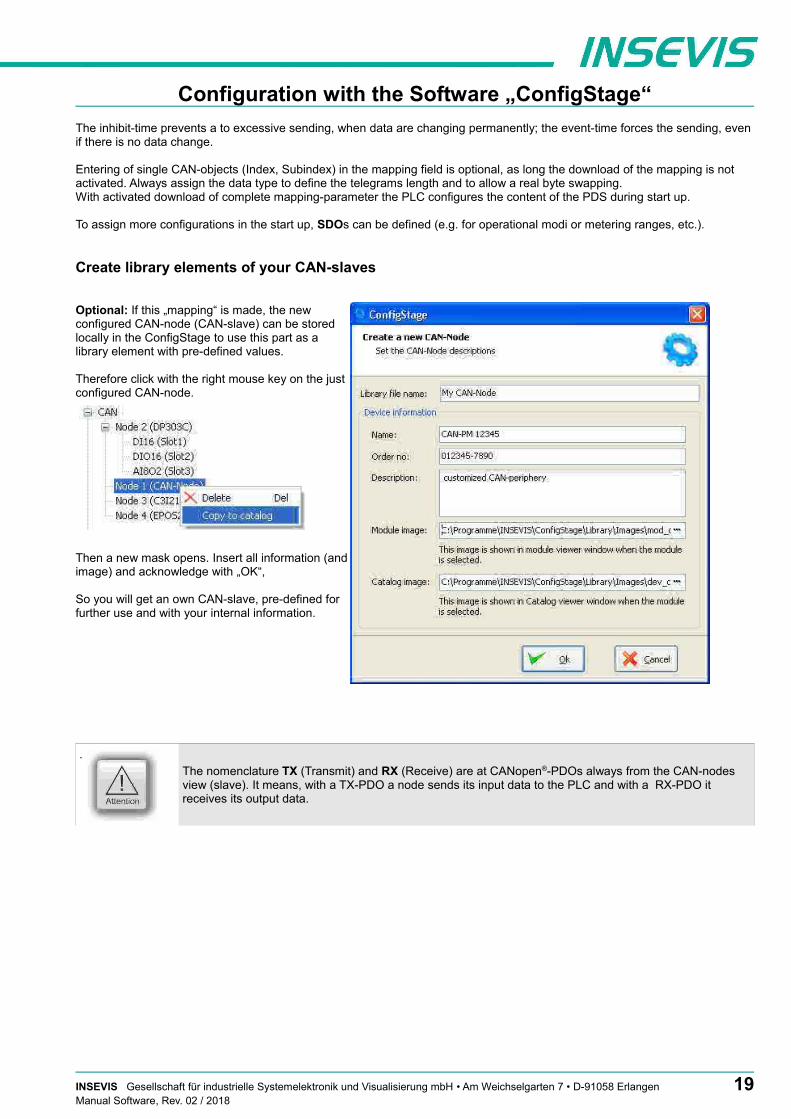
Create library elements of your CAN-slaves
Optional: If this „mapping“ is made, the newconfigured CAN-node (CAN-slave) can be storedlocally in the ConfigStage to use this part as alibrary element with pre-defined values.
Therefore click with the right mouse key on the justconfigured CAN-node.
Then a new mask opens. Insert all information (andimage) and acknowledge with „OK“,
So you will get an own CAN-slave, pre-defined forfurther use and with your internal information.
.
The nomenclature TX (Transmit) and RX (Receive) are at CANopen®-PDOs always from the CAN-nodes view (slave). It means, with a TX-PDO a node sends its input data to the PLC and with a RX-PDO it receives its output data.
INSEVIS Gesellschaft für industrielle Systemelektronik und Visualisierung mbH • Am Weichselgarten 7 • D-91058 Erlangen 19Manual Software, Rev. 02 / 2018

Configuration with the Software „ConfigStage“
Configure decentral external peripherie by EDS-file
You need a EDS-file of the externalCAN-slave you want to configure.Import it like shown here:
Than a new window opens like described above (Create library elements of your CAN-slave). After having assigned texts, order information and images there is an „empty“ library element, what must be configured like described in following items.
PDO configuration
By „Show CAN objects“ an object browser opens up with all CAN-objects available. These were filtered from the EDS-file automatically. Move single or multiple CAN-objects by Drag´n Drop into your configuration.
20 INSEVIS Gesellschaft für industrielle Systemelektronik und Visualisierung mbH • Am Weichselgarten 7 • D-91058 ErlangenManual Software, Rev. 02 / 2018
Configuration with the Software „ConfigStage“
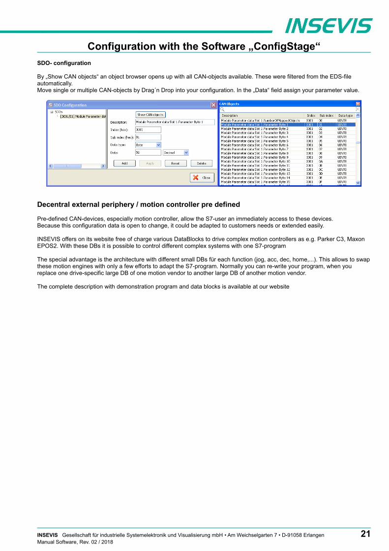
SDO- configuration
By „Show CAN objects“ an object browser opens up with all CAN-objects available. These were filtered from the EDS-file automatically. Move single or multiple CAN-objects by Drag´n Drop into your configuration. In the „Data“ field assign your parameter value.
Decentral external periphery / motion controller pre defined
Pre-defined CAN-devices, especially motion controller, allow the S7-user an immediately access to these devices. Because this configuration data is open to change, it could be adapted to customers needs or extended easily.
INSEVIS offers on its website free of charge various DataBlocks to drive complex motion controllers as e.g. Parker C3, Maxon EPOS2. With these DBs it is possible to control different complex systems with one S7-program
The special advantage is the architecture with different small DBs für each function (jog, acc, dec, home,...). This allows to swapthese motion engines with only a few efforts to adapt the S7-program. Normally you can re-write your program, when you replace one drive-specific large DB of one motion vendor to another large DB of another motion vendor.
The complete description with demonstration program and data blocks is available at our website
INSEVIS Gesellschaft für industrielle Systemelektronik und Visualisierung mbH • Am Weichselgarten 7 • D-91058 Erlangen 21Manual Software, Rev. 02 / 2018

Configuration with the Software „ConfigStage“
Samples for external CANopen devices
Sample for decentral CANopen periphery ref. to DS401If a device with digital and analog In- and outputs is used referring to CANopen-Profile DS401, the in/outs are
- digital inputs in TxPDO1, e.g. 32 bit - digital outputs in RxPDO1, e.g. 16 bit
- analog inputs in TxPDO2 to 4 - analog outputs in RxPDO2 to 4
Therewith the in- and outputs can be used on the configured S7-address (in this sample from EB0, AB0) as usually.
.
The PDO-number 1 is reserved for digital I/Os only. The analog I/Os can be mapped starting from PDO-number 2
22 INSEVIS Gesellschaft für industrielle Systemelektronik und Visualisierung mbH • Am Weichselgarten 7 • D-91058 ErlangenManual Software, Rev. 02 / 2018

Configuration with the Software „ConfigStage“
To transfer parameters (e.g. Metering ranges for analogmodules), SDOs need to be configured specific referring tothe vendor.
Sample configuration CANopen-drive controller ref. to DS402If a CANopen-drive controller ref. to profile DS402 is used, at least the controller-internal state machine must be managed by - a 16-bit control word and - 16-bit status word
Assign these both words to S7-operands by the PDO-mapping and than the controller can be driven by the S7-program.
INSEVIS Gesellschaft für industrielle Systemelektronik und Visualisierung mbH • Am Weichselgarten 7 • D-91058 Erlangen 23Manual Software, Rev. 02 / 2018

Visualization with the software „VisuStage“
Download and licensingThe actual version of VisuStage is free to download at INSEVIS websites in the download area.
At the first installation VisuStage asks for the license file. If not typed in, the software runs for 30 days with all functions as demo version and asks later again for that file. At the folders “Help” → “Info” can be added the path to a license file always ti upgrade a lean version into a full version.
This company license can be multiple times used within one company for multiple installations. (Open visustage.exe once as administrator in Windows 7 and Windows Vista. So you have to enter the license path only once).
System functionsThe S7 Operating system provides the system functions (SFC) to control the visualization by your S7 program. These SFCs aredescribed in the referring PLC-manual (Compact or Panel-PLC) at the chapter “System functions”
To use these SFCs you need the S7-Library from INSEVIS. It can be downloaded at download-area of INSEVIS websites for free. (e.g. Insevis_S7-library_from_2_0_17.zip - works from OS-version 2.0.17 and higher).
Communication between PLC and external Panel-HMIIn a Panel-PLC these SFCs will be used from one CPU for PLC- and panel function as well. If you use PLCs with external Panel please note, that
• Only single SFC-jobs can be processed. If the parameter "BUSY" of the corresponding SFC returns the value FALSE, the job is finished and a new SFC can be processed,
• The configuration of connection parameters of INSEVIS-Panel to INSEVIS-PLC or external PLC isexplained at the chapter “Resource Partner-PLC-device” in this manual
Use these data in the S7-program (e.g. LADDR := W#16#1 for the panel-connection with ID-No. 1)
Here the PLC can change the screens in an CALL „SFC 201external panel (e.g. with the connection-ID-No. 1 LADDR := W#16#1
SCREEN := MW1006RET VAL := MW1008BUSY := #busy
24 INSEVIS Gesellschaft für industrielle Systemelektronik und Visualisierung mbH • Am Weichselgarten 7 • D-91058 ErlangenManual Software, Rev. 02 / 2018

Visualization with the software „VisuStage“
General settings of the program shell
Top: Standard functions bar (self explaining or explained by tool-tips)
Alignment functions (2 and more objects)FIRST mark the Master-element, THAN mark the others, what shall be aligned to the masterthan choose the alignment property you want (left, horizontal centered, right, top, bottom centered, bottom)
Size functionsFIRST mark the Master-element, THAN mark the others, what shall be aligned to the masterthan choose the size item (width, height)or assign multiple dimension properties to different selected objects (right)with key-combination of CTRL+arrow-keys size of marked objects can be changed pixelwise
Alignment functions (1 or 3 and more objects)FIRST mark the Master-element, THAN mark the others, what shall be aligned to the masterFINALLY the element, what should mark the outer border of the gridthan choose the alignment property you want (same horizontal distance, center a single object, samevertical distance)
Grid-/ Snap functions (self explaining)At Extra / Settings assign grid size(de-) activate grid and snap by mouse click
General settings (without figure, self explaining)It is recommended to hide the panels bezel to save window-space on your VisuStage-PC.Grid and snap functions make it easier to design new screens
Top: General functions and drop down menus,
Left: Project browser with Resource settings, here theresources will be set up andparametrizedScreens (menus, view is selfconstructing,first screen is shown after boot-up)
Left Window of the projected Menue middle:
Right Display of the objects parametersmiddle: of the the selected object
Right: Tool bar with Project language (inthis language the project will bedisplayed)Function catalog with all objectswhat are availableLibrary catalog (to be assigned by one self)
Bottom: Message window (for messages, references, queries and filter results), to be switched on/off by F6-key
Demonstration projectThe following descriptions refer to the actual sample project what is available at the download area at INSEVIS websites. It requires the newest VisuStage-version and the newest operating systems at the devices.
It is hardly recommended to use this project together with this documentation to understand it better.
INSEVIS Gesellschaft für industrielle Systemelektronik und Visualisierung mbH • Am Weichselgarten 7 • D-91058 Erlangen 25Manual Software, Rev. 02 / 2018

Visualization with the software „VisuStage“
General functionalityVisuStage uses PLC-variables in different visualization objects in different screens. The source implements with images and texts (with the fonts from the VisuStage-PC) and will be compiled into a binary, what will be transferred to the Panel-HMI / PLC by Ethernet. The firmware in the Panel-HMI/-PLC creates the images and touch fields at the touch display there. No source datecan be read back from the Panel-HMI/-PLC. There is possible to get a remote on a PC-screen by RemoteStage, what requires the visualization binary (from the PC ord read back from the Panel-HMI/PLC - if you allow this).
Recommended proceduresA systematic working procedure reduces errors and decreases the programming effords
• Import your S7-variables from the S7-symbol table or directly from your S7-DBs• Assign objects for multiple screen use in different template screens, what you can use in every single
screen.• If you have finished entering all texts in your project language, you may export them into a *.csv-file and forward it to a
translator into any other language you need. It is only necessary to keep the *.csv structure then you can re-import this file again - and you have your next language texts.
• Collect all special pictures for your visualization theme before you start. (We strongly recommend the file format "png", because it works with a lossless compression and it allows definition of transparency by an alpha-channel. This is very important, if you want to see your background color on rounded corners and not any image colors.)
Save your resources It is very importand to have an eye on the memory size, required by the visualization. In general it is better totune your visualization with some easy hints, before you decrease the PLC performance with an unsuitablevisualization.
• Multiple use of buttons(if you use exactly the same buttons (resolution, image) you save lots of memory size because they will stored only one time as 1 object. It dies not matter, if symbols or texts belonging to this items or not.)
• Do not overlap dynamic objects(This function is not allowed by program cycle. You better navigate your images by dialog boxes with coords.)
• Better to have less screens with more common objects than to have lots of nearly empty screens.(Every new screen is stored as bmp and requires memory space.
Keep the overviewYou need to know, what resources are „active“ and what are „blind passengers“.
• Filters reduce the number of displayed resources to get a bettor overview.• With „cross reference“-function (right mouse button in the resource-menu) the use of variables, texts,
images, text lists, image lists and trends can be displayed. Delete resources you do not use.• Delete unused resources with the „CleanUp“-function at the rider „Edit“
Transfer your work to other projectsWhen you invested much time to create a very special head- or bottom line or navigation:Use the library function to export often used groups to you PC for a further use in other projects.
26 INSEVIS Gesellschaft für industrielle Systemelektronik und Visualisierung mbH • Am Weichselgarten 7 • D-91058 ErlangenManual Software, Rev. 02 / 2018

Visualization with the software „VisuStage“
Project settingsAt the menu „Project“ basic settings will be made.
Version counter• Manual assignment of a compile-no. or
automatic counter (can be displayed by textfield)
Assign the target IP-address• The connection between the PLC and the PC
with visualization software „VisuStage“isdone by Ethernet TCP/IP. That´s why it isnecessary to enter the IP-address of thetarget Panel-PLC/HMI to identify the devicewhereto the visualization should be send.
• (here you do not change the IP-addressdata of the Panel-PLC / HMI !)
• Double click on „Project“• Enter the data• Acknowledge
File formatsVisuStage creates 3 file formats:• *.vsproj contains the source code
of the visualization• *.res contains the resources
of the visualization• *.bin contains the compiled
binaries to be downloadedinto the panel
Data protection at binary upload• Request a PIN-code, when RemoteStage
shall be able to upload the binary of your visualization.
• Requested from RemoteStage beforeuploading visualization binary
• Must be activated when using “Onlinebackup” function in ServiceStage
VNC-Server (CPU-T devices only)• Select to start the VNC-Server always or
controlled by variable• Static / dynamic port number
(default port 5900 recommended!)• Password settings
(Needed in VNC-Client/Viewer)• Content in VNC-Client/Viewer
- passive (1:1 display only)- active (controls the HMI)- changeable by variable (e.g. key switch)
Using a VNC-Client/-Viewer as app makes possible a mobile application. The settings of operational and security functions depend on each app. Every user is responsible for data security by itself! Do not use VNC-Server without authentification and care for access of identified and known devices by yourself
INSEVIS Gesellschaft für industrielle Systemelektronik und Visualisierung mbH • Am Weichselgarten 7 • D-91058 Erlangen 27Manual Software, Rev. 02 / 2018
Visualization with the software „VisuStage“
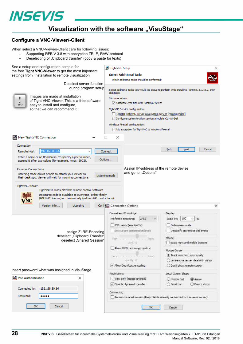
Configure a VNC-Viewer/-Client
When select a VNC-Viewer/-Client care for following issues:– Supporting RFB V 3.8 with encryption ZRLE, RAW-protocol– Deselecting of „Clipboard transfer“ (copy & paste for texts)
See a setup and configuration sample for the free Tight VNC-Viewer to get the most importantsettings from installation to remote visualization
Deselect server function during program setup
Images are made at installationof Tight VNC-Viewer. This is a free softwareeasy to install and configure,so that we can recommend it.
Assign IP-address of the remote devise and go to „Options“
assign ZLRE-Encodingdeselect „Clipboard Transfer“
deselect „Shared Session“
Insert password what was assigned in VisuStage
28 INSEVIS Gesellschaft für industrielle Systemelektronik und Visualisierung mbH • Am Weichselgarten 7 • D-91058 ErlangenManual Software, Rev. 02 / 2018
Visualization with the software „VisuStage“
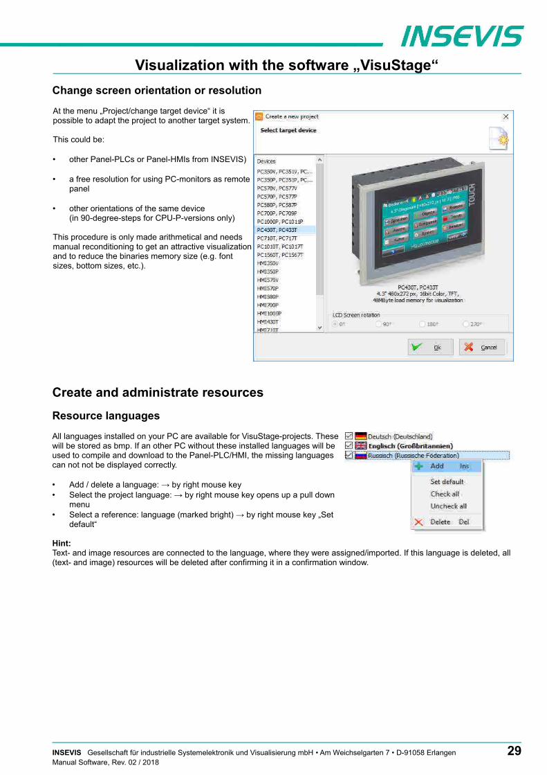
Change screen orientation or resolution
At the menu „Project/change target device“ it ispossible to adapt the project to another target system.
This could be:
• other Panel-PLCs or Panel-HMIs from INSEVIS)
• a free resolution for using PC-monitors as remotepanel
• other orientations of the same device (in 90-degree-steps for CPU-P-versions only)
This procedure is only made arithmetical and needsmanual reconditioning to get an attractive visualizationand to reduce the binaries memory size (e.g. fontsizes, bottom sizes, etc.).
Create and administrate resources
Resource languages
All languages installed on your PC are available for VisuStage-projects. Thesewill be stored as bmp. If an other PC without these installed languages will beused to compile and download to the Panel-PLC/HMI, the missing languagescan not not be displayed correctly.
• Add / delete a language: → by right mouse key• Select the project language: → by right mouse key opens up a pull down
menu• Select a reference: language (marked bright) → by right mouse key „Set
default“
Hint:Text- and image resources are connected to the language, where they were assigned/imported. If this language is deleted, all (text- and image) resources will be deleted after confirming it in a confirmation window.
INSEVIS Gesellschaft für industrielle Systemelektronik und Visualisierung mbH • Am Weichselgarten 7 • D-91058 Erlangen 29Manual Software, Rev. 02 / 2018
Visualization with the software „VisuStage“
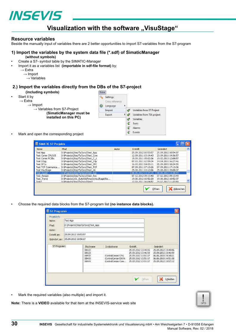
Resource variablesBeside the manually input of variables there are 2 better opportunities to import S7-variables from the S7-program
1) Import the variables by the system data file (*.sdf) of SimaticManager(without symbols)
• Create a S7- symbol table by the SIMATIC-Manager• Import it as a variables list (importable in sdf-file format) by:
→ Extra → Import → Variables
2.) Import the variables directly from the DBs of the S7-project(including symbols)
• Start it by → Extra
→ Import → Variables from S7-Project
(SimaticManager must be installed on this PC)
• Mark and open the corresponding project
• Choose the required data blocks from the S7-program list (no instance data blocks).
• Mark the required variables (also multiple) and import it.
Note: There is a VIDEO available for that item at the INSEVIS-service web site
30 INSEVIS Gesellschaft für industrielle Systemelektronik und Visualisierung mbH • Am Weichselgarten 7 • D-91058 ErlangenManual Software, Rev. 02 / 2018
Visualization with the software „VisuStage“
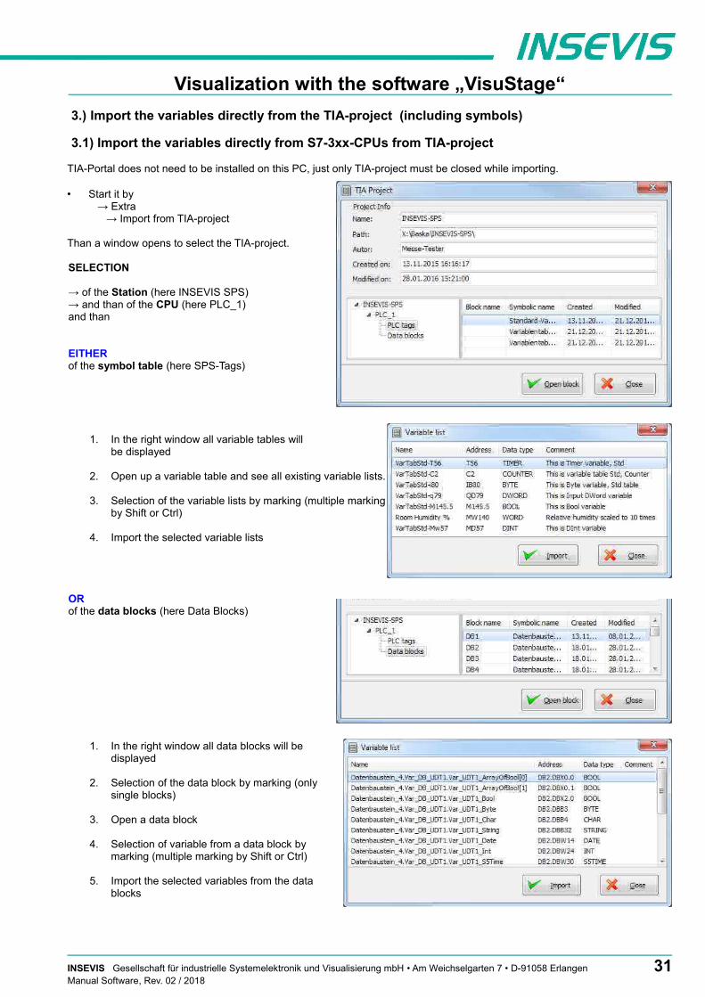
3.) Import the variables directly from the TIA-project (including symbols)
3.1) Import the variables directly from S7-3xx-CPUs from TIA-project
TIA-Portal does not need to be installed on this PC, just only TIA-project must be closed while importing.
• Start it by → Extra → Import from TIA-project
Than a window opens to select the TIA-project.
SELECTION
→ of the Station (here INSEVIS SPS)→ and than of the CPU (here PLC_1)and than
EITHERof the symbol table (here SPS-Tags)
1. In the right window all variable tables will be displayed
2. Open up a variable table and see all existing variable lists.
3. Selection of the variable lists by marking (multiple markingby Shift or Ctrl)
4. Import the selected variable lists
ORof the data blocks (here Data Blocks)
1. In the right window all data blocks will bedisplayed
2. Selection of the data block by marking (onlysingle blocks)
3. Open a data block
4. Selection of variable from a data block bymarking (multiple marking by Shift or Ctrl)
5. Import the selected variables from the datablocks
INSEVIS Gesellschaft für industrielle Systemelektronik und Visualisierung mbH • Am Weichselgarten 7 • D-91058 Erlangen 31Manual Software, Rev. 02 / 2018

Visualization with the software „VisuStage“
3.2) Import the variables directly from S7-12xx and 15xx CPUs from TIA-project
To import variables from projects which are based on CPUs from the 1200 and 1500 series they have to be stored inside a data block.
To achive this execute the following steps in your TIA project:
1. Select your CPU -> Program blocks -> Add new block
2. Select in the opened menue the type "Data block" and enter a name.Press OK to create the data block
3. In this new data block you can now create variables with name, data type and offset which can later be imported into the VisuStage.
32 INSEVIS Gesellschaft für industrielle Systemelektronik und Visualisierung mbH • Am Weichselgarten 7 • D-91058 ErlangenManual Software, Rev. 02 / 2018

Visualization with the software „VisuStage“
To ensure a flawless communication between RemoteStage and S7-CPUs 12xx / 15xx, the block access must not be optimized.(only for S7-12xx and 15xx)
To achive this execute the following steps in your TIA project:
1. Select your CPU -> Program blocks
2. Do a right click on the concerningblock and select "Properties..."
Execute the following steps in the opened window:
1. Select "Attributes"
2. Deactivate the option "Optimizedblock access"
INSEVIS Gesellschaft für industrielle Systemelektronik und Visualisierung mbH • Am Weichselgarten 7 • D-91058 Erlangen 33Manual Software, Rev. 02 / 2018

Visualization with the software „VisuStage“
In following cases VisuStage wants a confirmation before it starts a variable import:• A variable with the same name exists already, but with another address or data type• A variable with the same address exists already, but with another name or data type• A variable with the same name and address exists already, but with another data type
Caution: When VisuStage overwrites the variables, the connections between variables and its objects will be kept.When deleting the variables manually these connections will be deleted as well.
The Export of the variables is done in the same formats as well:• sdf- file format (System data format, variables only), or in• sym- file format (Symbol table format with variables and data blocks)
Set filter or find variables
Variables can be filtered for:• Name• Address- and• Data type
In the sample all variables are filtered, what • contain „Var“ in the name,• are defined as „Merker“ and• with data type „BYTE“
Cross references for variablesTo keep the overview about the variables used in the project, there is a function „Cross reference“ (mark a variable and use rightmouse button). All variables will be displayed referring to their usage in resources or in menu objects.
By a double click on an item you get automatically into the menu, where it is used. Close/open the message window by key „F6“.
34 INSEVIS Gesellschaft für industrielle Systemelektronik und Visualisierung mbH • Am Weichselgarten 7 • D-91058 ErlangenManual Software, Rev. 02 / 2018

Visualization with the software „VisuStage“
Find variables by text phrases Clean up unused variablesFind resources with the „Find“-function <CTRL+F> Delete unused resources with the „CleanUp“-functionat the rider „Edit“ to keep an overview. at the rider „Edit“ and keep your project small and simple.
The result is shown in the message window (show/hide with key „F6“)
Multiplex-variables
From V 2.0.5.3 it is possible to create multiplex variables.
At the resource “Variable”, at the rider “Multiplex variables” a listof variables can be created (see sample right beside).
Only whole-number variables will be accepted as indexvariable, the variables in the variable list are free (STRNG-typesare not to mix with other types).
It also can be DBs, Merkers, inputs or outputs.
With multiplex variables e.g. I/O-fields can be multiple used.Depending on the value of the index-variable pre-assignedmultiplex-variables are displayed at runtime.
INSEVIS Gesellschaft für industrielle Systemelektronik und Visualisierung mbH • Am Weichselgarten 7 • D-91058 Erlangen 35Manual Software, Rev. 02 / 2018
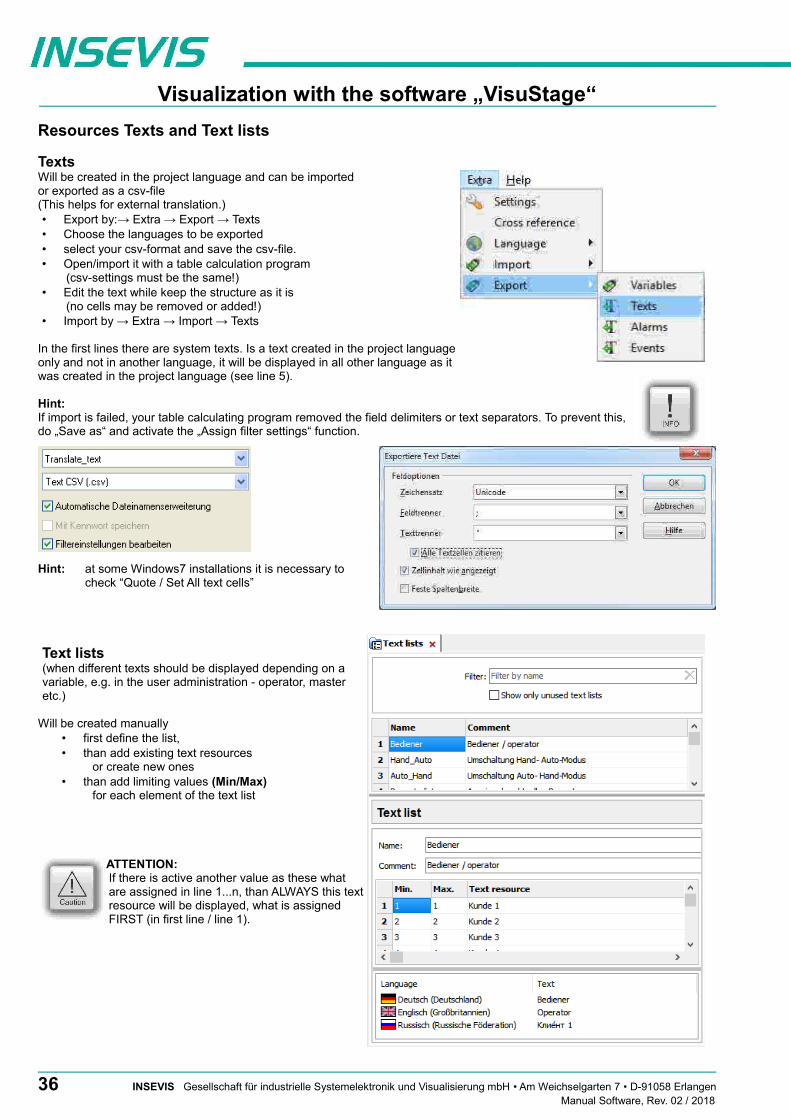
Visualization with the software „VisuStage“
Resources Texts and Text lists
Texts Will be created in the project language and can be imported or exported as a csv-file (This helps for external translation.)• Export by:→ Extra → Export → Texts• Choose the languages to be exported• select your csv-format and save the csv-file.• Open/import it with a table calculation program
(csv-settings must be the same!)• Edit the text while keep the structure as it is
(no cells may be removed or added!)• Import by → Extra → Import → Texts
In the first lines there are system texts. Is a text created in the project languageonly and not in another language, it will be displayed in all other language as itwas created in the project language (see line 5).
Hint:If import is failed, your table calculating program removed the field delimiters or text separators. To prevent this,do „Save as“ and activate the „Assign filter settings“ function.
Hint: at some Windows7 installations it is necessary tocheck “Quote / Set All text cells”
Text lists(when different texts should be displayed depending on avariable, e.g. in the user administration - operator, masteretc.)
Will be created manually• first define the list,• than add existing text resources
or create new ones• than add limiting values (Min/Max)
for each element of the text list
ATTENTION: If there is active another value as these what are assigned in line 1...n, than ALWAYS this textresource will be displayed, what is assignedFIRST (in first line / line 1).
36 INSEVIS Gesellschaft für industrielle Systemelektronik und Visualisierung mbH • Am Weichselgarten 7 • D-91058 ErlangenManual Software, Rev. 02 / 2018

Visualization with the software „VisuStage“
Cross references for texts / text listsTo keep the overview about the texts/ text lists used in the project, there is a function „Cross reference“ in the resource pool. (Go to resources Text/ text list, mark a text/ text list and use right mouse button). All texts / text lists will be displayed referring to their usage in resources or in menu objects.
By a double click on an item you get automatically into the menu, where it is used. Close/open the message window by „F6“.
Find texts / text lists by text phrases Clean up unused texts / text listsFind resources with the „Find“-function <CTRL+F> Delete unused resources with the „CleanUp“-functionat the rider „Edit“ to keep an overview. at the rider „Edit“ and keep your project small and simple.
The result is shown in the message window (show/hide with key „F6“)
INSEVIS Gesellschaft für industrielle Systemelektronik und Visualisierung mbH • Am Weichselgarten 7 • D-91058 Erlangen 37Manual Software, Rev. 02 / 2018

Visualization with the software „VisuStage“
Resources Images and Image lists
ImagesINSEVIS delivers some sample images with the VisuStage. Creating own images is a child´s play by any free software. We did use „PhotoFiltre“ for that.
• Recommended file format: PNG because of the transparent alpha-channel. Substitute a color by transparency and save the image as PNG (Interlaced / Automatic recommended).
• Images of the project-language will be used for all other languages as well→ shown half transparency
• It is possible to use other images in other languages instead the image of the project language→ by right mouse key assign a new one and it will be shown with full color
Image lists(the best tool for color changes or screen changes caused by changing variable values)
Will be created manually• right mouse key in the field Name,
(add the new name of the image list )
• Add limiting values for each element of the image list
• Assign an existing image resource, (or add a new one in this field directly)
From V2.0.3.5 the image resources used in the image listswill be displayed below to keep a better overview
ATTENTION: If there is active another value as these what are assigned in line 1...n, than ALWAYS thisimage resource will be displayed, what is assigned FIRST (in first line / line 1).
38 INSEVIS Gesellschaft für industrielle Systemelektronik und Visualisierung mbH • Am Weichselgarten 7 • D-91058 ErlangenManual Software, Rev. 02 / 2018

Visualization with the software „VisuStage“
Cross references for images / image listsTo keep the overview about the images / image lists used in the project, there is a function „Cross reference“ (mark a image / image list and use right mouse button). All images / image lists will be displayed referring to their usage in resources or in menu objects.
By a double click on an item you get automatically into the menu, where it is used. Close/open the message window by key „F6“.
Find images/image lists by text phrases Clean up unused images/image listsFind resources with the „Find“-function <CTRL+F> Delete unused resources with the „CleanUp“-functionat the rider „Edit“ to keep an overview. at the rider „Edit“ and keep your project small and simple.
The result is shown in the message window (show/hide with key „F6“)
INSEVIS Gesellschaft für industrielle Systemelektronik und Visualisierung mbH • Am Weichselgarten 7 • D-91058 Erlangen 39Manual Software, Rev. 02 / 2018
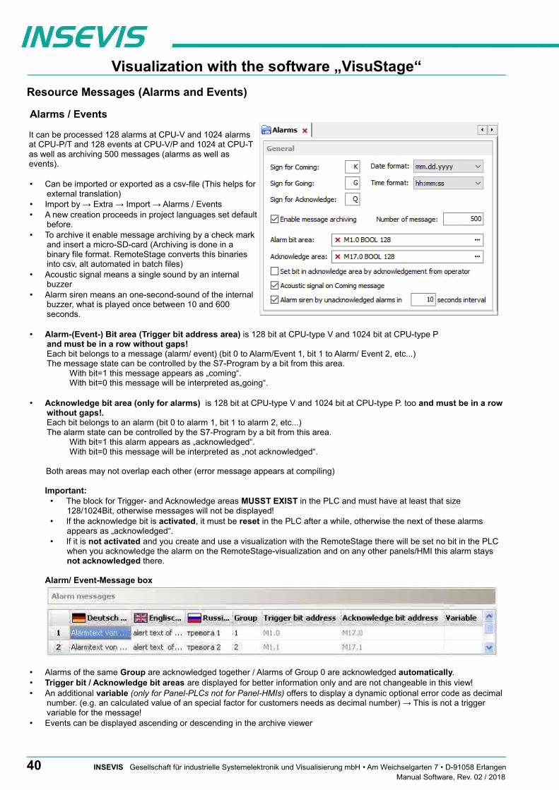
Visualization with the software „VisuStage“
Resource Messages (Alarms and Events)
Alarms / Events
It can be processed 128 alarms at CPU-V and 1024 alarmsat CPU-P/T and 128 events at CPU-V/P and 1024 at CPU-Tas well as archiving 500 messages (alarms as well asevents).
• Can be imported or exported as a csv-file (This helps forexternal translation)
• Import by → Extra → Import → Alarms / Events• A new creation proceeds in project languages set default
before.• To archive it enable message archiving by a check mark
and insert a micro-SD-card (Archiving is done in abinary file format. RemoteStage converts this binariesinto csv, alt automated in batch files)
• Acoustic signal means a single sound by an internalbuzzer
• Alarm siren means an one-second-sound of the internalbuzzer, what is played once between 10 and 600seconds.
• Alarm-(Event-) Bit area (Trigger bit address area) is 128 bit at CPU-type V and 1024 bit at CPU-type P and must be in a row without gaps!Each bit belongs to a message (alarm/ event) (bit 0 to Alarm/Event 1, bit 1 to Alarm/ Event 2, etc...)The message state can be controlled by the S7-Program by a bit from this area.
With bit=1 this message appears as „coming“. With bit=0 this message will be interpreted as„going“.
• Acknowledge bit area (only for alarms) is 128 bit at CPU-type V and 1024 bit at CPU-type P. too and must be in a row without gaps!. Each bit belongs to an alarm (bit 0 to alarm 1, bit 1 to alarm 2, etc...)The alarm state can be controlled by the S7-Program by a bit from this area.
With bit=1 this alarm appears as „acknowledged“. With bit=0 this message will be interpreted as „not acknowledged“.
Both areas may not overlap each other (error message appears at compiling)
Important: • The block for Trigger- and Acknowledge areas MUSST EXIST in the PLC and must have at least that size
128/1024Bit, otherwise messages will not be displayed!• If the acknowledge bit is activated, it must be reset in the PLC after a while, otherwise the next of these alarms
appears as „acknowledged“.• If it is not activated and you create and use a visualization with the RemoteStage there will be set no bit in the PLC
when you acknowledge the alarm on the RemoteStage-visualization and on any other panels/HMI this alarm stays not acknowledged there.
Alarm/ Event-Message box
• Alarms of the same Group are acknowledged together / Alarms of Group 0 are acknowledged automatically.• Trigger bit / Acknowledge bit areas are displayed for better information only and are not changeable in this view!• An additional variable (only for Panel-PLCs not for Panel-HMIs) offers to display a dynamic optional error code as decimal
number. (e.g. an calculated value of an special factor for customers needs as decimal number) → This is not a trigger variable for the message!
• Events can be displayed ascending or descending in the archive viewer
40 INSEVIS Gesellschaft für industrielle Systemelektronik und Visualisierung mbH • Am Weichselgarten 7 • D-91058 ErlangenManual Software, Rev. 02 / 2018

Visualization with the software „VisuStage“
Resource User administration
There can administrated be up to 9 users with passwords by 8 digit - PIN-codes. Users with level 9 have all access rights, thosewith level 1 have least access rights.
In the upper mask can be assigned
• the target screens, whereto the project should changeafter login/ logout or
if there shall be called the PIN-input dialog directly aftertouching a button with access rights.
and
• an automatic logout time (in minutes). (With logout time 0 is assigned no automatic logout.)
and
• a variable, what informs the PLC, what user level isactive yet
and
• an additional query to identify the user level before PIN input
In the lower mask can be assigned
• the user names and PIN-codes of each levels (1...9).
• A new user will be added by entering its name and PIN-code
“Query user level by PIN input”
Just before entering PIN code it ispossible to activate a identificationmask, where the user enters his level.
Hint: • The target menu screen after successfully log in will be assigned at the dynamic object „PIN-input field“• With the PIN-Change dialog- function a PIN can be changed by the operator (his level stays the same).
If this PIN is forgotten, a new upload of the visualization binary can set it back to delivery state.• For a user-level-referring screen change use the function „Change screen with PIN input“ on a button.
INSEVIS Gesellschaft für industrielle Systemelektronik und Visualisierung mbH • Am Weichselgarten 7 • D-91058 Erlangen 41Manual Software, Rev. 02 / 2018

Visualization with the software „VisuStage“
Change user level by SFC215 "LOGIN"
The SFC215 "LOGIN" enables the user level change by S7-User program at Runtime.
Parameter Declaration Data type Description
LADDR INPUT WORD Logical base address = 0 (for all Panel-PLC)Logical base address = 1..16 (Connection ID number to Panel-HMI)
LEVEL INPUT BYTE User level (1..9)0 = Logout current user level
RET_VAL OUTPUT WORD Error codeW#16#0000 – No errorW#16#8002 – VisuStage is not runningW#16#8005 – Level is invalid or not configuredW#16#8xyy – General error codes (compatible to STEP 7)
only for Panel-HMI:W#16#7000 – Job is in processW#16#7001 – Invalid connection state e.g not connectedW#16#7002 – Job is not accepted, because another job is proceeded actuallyW#16#7003 – Connection resource occupied (temporarily locked)W#16#8001 – Invalid connection ID number or connection is not configured
BUSY OUTPUT BOOL TRUE: Job is in processing
S7-User program example to change user level 7
Target: Change to user level 7
UN M 1502.4 // if change request is not set, then BEB // end the function
CALL SFC 215 LADDR :=MW2000 // VisuStage connection ID number. // In Panel-PLC (e.g PC710T) must be W#16#0. LEVEL :=B#16#7 // User level, could be 0..9
// 0= Logout current user level RET_VAL:=MW1000 // Return / result code BUSY :=M1702.3 // TRUE = Reading is in process
U M 1702.3 // Job is in process BEB R M 1502.4 // reset request signal
L MW 1000 // return / result code L 0 // no error ==I // If no error, then BEB // end the function
L MW 1000 // error occurred // error evaluation // ...
BEA // end of function
42 INSEVIS Gesellschaft für industrielle Systemelektronik und Visualisierung mbH • Am Weichselgarten 7 • D-91058 ErlangenManual Software, Rev. 02 / 2018

Visualization with the software „VisuStage“
Resource Partner-PLC (for HMI only)
INSEVIS HMIs run with data types of S7-300-family only. They use Ethernet S7-communication (Put/Get) to communicate The HMI communicates with its partner device by via Ethernet S7-communication. IN that communication INSEVIS-HMIs are the ACTIVE part. The referring partner-device will be identified by IP-address and TSAP (made of rack-no. / slot-no. of CPU / ID-no.of this connection resource). One HMI can only communicate with ONE partner-device (CPU).
Connection setting in the HMI• Either assign it in the BIOS of the Panel-HMIs (put out the Ethernet-cable, wait for the logo in the screen and than
press left/right/left side of the screen) or• in VisuStage-project at the resource partner device
Connection settings in the Partner-device• If the PLC do not shall change screens or languages in the HMI, no connection must be assigned there.
The PLC is using connection resource with ID-no 02 (reserved for OP-communication).• If the PLC shall change screens and languages at the INSEVIS-HMI, an Ethernet connection with connection resource
ID >03 must be assigned (e.g. in ConfigStage or in Siemens-programmiing tool)
below: assignment of connection parameter below: assignment of connection parameterat HMI´s view in the VisuStage at PLC´s view in the ConfigStage
For INSEVIS-Panels and Siemens-CPUs1. Assign the IP-address of the partner-PLC into the field „Partner-PLC“ in VisuStage-project or in HMI-BIOS2. Configure the TSAP by assigning rack-no / CPU-slot- no/ ID-no of the connection resource
for Siemens-CPUs 300/ 400 it is 0, 2, 02, for Siemens-CPUs 1200/1500 it is 0, 1, 02 → allow “Put/Get” communication
→ do not use optimized DBs
Partner-PLC Synchronization (for HMI only)
When assigning partner device a time synchronization between panel and PLC is recommended. → Please see above screenshot
1st check box: The HMI will be synchronized to the PLC-time2nd check box: The PLC-time can be changed by the panel at runtime
Attention:
If you do not synchronize panel and PLC the difference between both devices may lead to unexpected program behavior.
INSEVIS Gesellschaft für industrielle Systemelektronik und Visualisierung mbH • Am Weichselgarten 7 • D-91058 Erlangen 43Manual Software, Rev. 02 / 2018
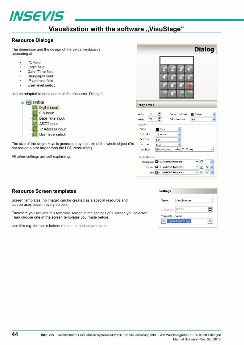
Visualization with the software „VisuStage“
Resource Dialogs
The dimension and the design of the virtual keyboards appearing at
• I/O-field, • Login field, • Date-/Time field• Stringinput field• IP-address field• User level select
can be adapted to ones needs in the resource „Dialogs“.
The size of the single keys is generated by the size of the whole object (Donot assign a size larger than the LCD-resolution!)
All other settings are self explaining.
Resource Screen templates
Screen templates (no image) can be created as a special resource and can be uses once in every screen.
Therefore you activate this template screen in the settings of a screen you selected.Than choose one of the screen templates you made before.
Use this e.g. for top or bottom menus, headlines and so on..
44 INSEVIS Gesellschaft für industrielle Systemelektronik und Visualisierung mbH • Am Weichselgarten 7 • D-91058 ErlangenManual Software, Rev. 02 / 2018

Visualization with the software „VisuStage“
Resources Trends
There can be processed 4 trends with 16 channels each.This represent values by time, smallest time base is 1sec. All 16 channels of one trend need to have the samedata format.
Trends will get a name - here “Druck” (pressure), whatwill be used for displaying and storing at RemoteStageas file name.
Samples: here you enter the number of samples in thecircular buffer in runtime (100...200)
Start behavior: Beside S7-SFCs there are 3 additionalways to start a trending
• manually / by demand by assigning a function“Trend Start” to a button→ Configuration at the function (limitedarchiving functionality to stay compatible to oldversions)
• with each system start→ Configuration at the trend resource settings
• depending on a variable→ Configuration at the trend resource settings
If Archive was activated, you can• enter the number of samples you want to
archive in the Circular archive (max. 65635samples per each trend channel) or
• combine up to 10 circular archives on the Micro-SD-card to an Segmented circular archive to656.350 samples per each trend channel todisplay it in the trend archive viewer.
When number of samples exceed these limits, they willbe overwritten in the FIFO system.
To configure the trend channel values, assign min/maxvalues, decimal point, color, style (interpolated – shortestconnection between 2 sample values, bars (vertically), stepped) and design of the sample point markers (diverse).
Archives will be archived to the external Micro-SD-card only. Each trend will be saved as own file. This binary will be converted by the software „RemoteStage“ on the PC into a csv- format either manually or in “Planned Tasks” of your Windows-PC. These archives can be deleted from Micro-SD-card by an special SFC, assigned as function to a button.
Cross references for trendsTo keep the overview about the trends started, stopped, continued or displayed) in the project, there is a function „Cross reference“ (mark a trend and use right mouse button). All trend handling will be displayed referring to their usage in resources orin menu objects. By a double click on an item you get automatically into the menu, where it is used. Close/open the message window by key „F6“.
INSEVIS Gesellschaft für industrielle Systemelektronik und Visualisierung mbH • Am Weichselgarten 7 • D-91058 Erlangen 45Manual Software, Rev. 02 / 2018

Visualization with the software „VisuStage“
Starting the trend sampling with SFC 202 "TRENDSRT"
To start the configured Trend use SFC202 "TRENDSRT". The sampling interval and number of samples are assigned to the trend. After starting, operating system samples the configured operand values in given interval and stores to Micro-SD card if „ARCHIVE“ parameter set to „TRUE“. If „CYCLIC“ parameter is „FALSE“, the „COUNT“ samples are one time sampled and trend automatically changes to „STOP“ state.
Trends are written to „trend_xxx.bin“ whereas xxx is Trend ID number. This archive file is based on „Ring-Buffer“ mechanism with „COUNT“ samples.
(Trend data can be get out of the PLC by SD-card only. In future versions a download by Ethernet will be possible.
Parameter Declaration Data type Description
LADDR INPUT WORD Logical base address = 0 (for all Panel-PLCs)Logical base address = 1...16 (connection-ID-No. to the Panel-HMI)
TREND INPUT INT Trend ID number, (from VisuStage configured @ resources)
INTERVAL INPUT WORD Sampling interval in seconds. 1..65535 second are allowed.
COUNT INPUT WORD Number of samples to sample / to archive. 1..65535 are valid.
CYCLIC INPUT BOOL TRUE: It cyclically samples the COUNT samples.FALSE: One time samples the COUNT samples, then stops the sampling
ARCHIVE INPUT BOOL TRUE: Sampled values are stored in microSD cardFALSE: No archive
RET_VAL OUTPUT WORD Error codeW#16#0000 – No errorW#16#8002 – VisuStage is not running/configuredW#16#8003 – Invalid „TREND“ ID numberW#16#8004 – Invalid state / Already started.W#16#8005 – Invalid „INTERVAL“ valueW#16#8006 – Invalid „COUNT“ valueW#16#8xyy – General error codes (compatible to STEP®7)only for Panel-HMI: W#16#7000 – Job is in processW#16#7001 – Invalid connection state, e.g not connectedW#16#7002 – Job not accepted, because another job is proceeded actuallyW#16#7003 – Connection resource occupied (temporarily locked)W#16#8001 – Invalid connection ID number or connection is not configured
BUSY OUTPUT BOOL Busy flag, TRUE Job is in processing
If a trend is started once and the PLC has got a power OFF, the trend starts after power ON by itselfe automatically.
→ Here you will find more for parameterizing of the objects Trend viewer and trend archive viewer
46 INSEVIS Gesellschaft für industrielle Systemelektronik und Visualisierung mbH • Am Weichselgarten 7 • D-91058 ErlangenManual Software, Rev. 02 / 2018

Visualization with the software „VisuStage“
S7-program sample for using the SFC202
Purpose: Start trend (ID number =6163) with configuration: • 1s interval, • cyclically, • with archiving, • ring buffer size 65535 samples (set of values)
UN M 1500.2 // if request is not set, then BEB // end the function
CALL SFC 202 LADDR :=W#16#0 // VisuStage connection ID number. // In Panel-PLC (e.g PC700P) must be W#16#0. TREND :=6163 // ID number of trend, which is configured in VisuStage INTERVAL:=W#16#1 // every 1s samples the values COUNT :=W#16#FFFF // max. no. of samples (set of values) 65535 (dez) => FFFF (hex) CYCLIC :=TRUE // cyclically samples as ring buffer. // Buffer size is given in COUNT parameter ARCHIVE :=TRUE // enables the archiving in micro SD card RET_VAL :=MW1000 // Result / return code BUSY :=M1700.2 // TRUE = Request is in process
U M 1700.2 // If Start the trend is in process, then BEB // end this function R M 1500.2 // reset request signal
L MW 1000 // return / result code L 0 // no error ==I // If no error, then BEB // end the function
L MW 1000 // error occurred // error evaluation // ...
BEA // end of function
INSEVIS Gesellschaft für industrielle Systemelektronik und Visualisierung mbH • Am Weichselgarten 7 • D-91058 Erlangen 47Manual Software, Rev. 02 / 2018

Visualization with the software „VisuStage“
Stopping the trend sampling with SFC 203 "TRENDSTP"
The trend sampling can be stopped by SFC 204 “TRENDSTP“ function call.
Parameter Declaration Data type Description
LADDR INPUT WORD Logical base address = 0 (for all Panel-PLCs)Logical base address = 1...16 (connection-ID-No. to the Panel-HMI)
TREND INPUT INT Trend ID number, (from VisuStage configured @ resources)
RET_VAL OUTPUT WORD Error codeW#16#0000 – No errorW#16#8002 – VisuStage is not running/configuredW#16#8003 – Invalid „TREND“ ID numberW#16#8xyy – General error codes (compatible to STEP®7)only for Panel-HMI: W#16#7000 – Job is in processW#16#7001 – Invalid connection state, e.g not connectedW#16#7002 – Job not accepted, because another job is proceeded actuallyW#16#7003 – Connection resource occupied (temporarily locked)W#16#8001 – Invalid connection ID number or connection is not configured
BUSY OUTPUT BOOL Busy flag, TRUE Job is in processing
S7-program sample for using the SFC202
Purpose: Stop the trend with ID number 6163
UN M 1500.3 // if request is not set, then BEB // end the function
CALL SFC 203 LADDR :=W#16#0 // VisuStage connection ID number. // In Panel-PLC (e.g PC700P) must be W#16#0. TREND :=6163 // ID number of trend, which is configured in VisuStage RET_VAL:=MW1000 // Result / return code BUSY :=M1700.3 // TRUE = Request is in process
U M 1700.3 // If top the trend is in process, then BEB // end this function R M 1500.3 // reset request signal
L MW 1000 // return / result code L 0 // no error ==I // If no error, then BEB // end the function
L MW 1000 // error occurred // error evaluation // ...
BEA // end of function
48 INSEVIS Gesellschaft für industrielle Systemelektronik und Visualisierung mbH • Am Weichselgarten 7 • D-91058 ErlangenManual Software, Rev. 02 / 2018

Visualization with the software „VisuStage“
Continue the trend sampling with SFC 204 "TRENDCNT"
The previously stopped trend sampling could be continued by calling SFC 204 “TRENDCNT“.
The sampling interval must be new assigned. The number of samples and sampling mode (cyclical overwriting, archiving) are kept as last assigned.
Parameter Declaration Data type Description
LADDR INPUT WORD Logical base address = 0 (for all Panel-PLCs)Logical base address = 1...16 (connection-ID-No. to the Panel-HMI)
TREND INPUT INT Trend ID number, (from VisuStage configured @ resources)
INTERVAL INPUT WORD Sampling interval in seconds. 1..65535 second are allowed.
RET_VAL OUTPUT WORD Error codeW#16#0000 – No errorW#16#8002 – VisuStage is not running/configuredW#16#8003 – Invalid „TREND“ ID numberW#16#8004 – Trend was not started or Sampling count reached to zero.W#16#8xyy – General error codes (compatible to STEP®7)only for Panel-HMI: W#16#7000 – Job is in processW#16#7001 – Invalid connection state, e.g not connectedW#16#7002 – Job not accepted, because another job is proceeded actuallyW#16#7003 – Connection resource occupied (temporarily locked)W#16#8001 – Invalid connection ID number or connection is not configured
BUSY OUTPUT BOOL Busy flag, TRUE Job is in processing
→ Here you will find more for parameterizing of the objects Trend viewer and trend archive viewer
S7-program sample for using the SFC204
Purpose: Continue / resume the trend with ID number 6163
UN M 1500.4 // if request is not set, then BEB // end the function
CALL SFC 204 LADDR :=W#16#0 // VisuStage connection ID number. // In Panel-PLC (e.g PC700P) must be W#16#0. TREND :=6163 // ID number of trend, which is configured in VisuStage INTERVAL:=W#16#1 // every 1s samples the values RET_VAL :=MW1000 // Result / return code BUSY :=M1700.4 // TRUE = Request is in process
U M 1700.4 // If Resume the trend is in process, then BEB // end this function R M 1500.4 // reset request signal
L MW 1000 // return / result code L 0 // no error ==I // If no error, then BEB // end the function
L MW 1000 // error occurred // error evaluation // ...
BEA // end of function
INSEVIS Gesellschaft für industrielle Systemelektronik und Visualisierung mbH • Am Weichselgarten 7 • D-91058 Erlangen 49Manual Software, Rev. 02 / 2018
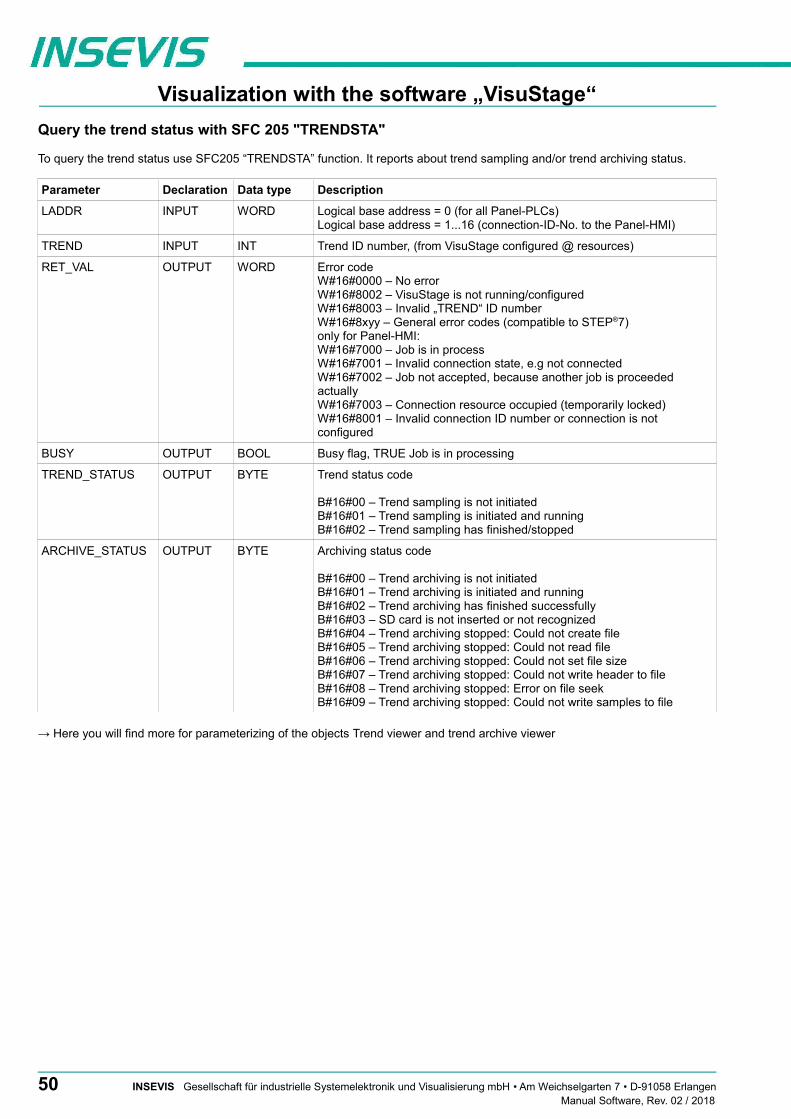
Visualization with the software „VisuStage“
Query the trend status with SFC 205 "TRENDSTA"
To query the trend status use SFC205 “TRENDSTA” function. It reports about trend sampling and/or trend archiving status.
Parameter Declaration Data type Description
LADDR INPUT WORD Logical base address = 0 (for all Panel-PLCs)Logical base address = 1...16 (connection-ID-No. to the Panel-HMI)
TREND INPUT INT Trend ID number, (from VisuStage configured @ resources)
RET_VAL OUTPUT WORD Error codeW#16#0000 – No errorW#16#8002 – VisuStage is not running/configuredW#16#8003 – Invalid „TREND“ ID numberW#16#8xyy – General error codes (compatible to STEP®7)only for Panel-HMI: W#16#7000 – Job is in processW#16#7001 – Invalid connection state, e.g not connectedW#16#7002 – Job not accepted, because another job is proceeded actuallyW#16#7003 – Connection resource occupied (temporarily locked)W#16#8001 – Invalid connection ID number or connection is not configured
BUSY OUTPUT BOOL Busy flag, TRUE Job is in processing
TREND_STATUS OUTPUT BYTE Trend status code
B#16#00 – Trend sampling is not initiatedB#16#01 – Trend sampling is initiated and runningB#16#02 – Trend sampling has finished/stopped
ARCHIVE_STATUS OUTPUT BYTE Archiving status code
B#16#00 – Trend archiving is not initiatedB#16#01 – Trend archiving is initiated and runningB#16#02 – Trend archiving has finished successfullyB#16#03 – SD card is not inserted or not recognizedB#16#04 – Trend archiving stopped: Could not create fileB#16#05 – Trend archiving stopped: Could not read fileB#16#06 – Trend archiving stopped: Could not set file sizeB#16#07 – Trend archiving stopped: Could not write header to fileB#16#08 – Trend archiving stopped: Error on file seekB#16#09 – Trend archiving stopped: Could not write samples to file
→ Here you will find more for parameterizing of the objects Trend viewer and trend archive viewer
50 INSEVIS Gesellschaft für industrielle Systemelektronik und Visualisierung mbH • Am Weichselgarten 7 • D-91058 ErlangenManual Software, Rev. 02 / 2018

Visualization with the software „VisuStage“
S7-program sample for using the SFC205
Purpose: Check the status of trend with ID number 6163
UN M 1500.5 // if request is not set, then BEB // end the function
CALL SFC 205 LADDR :=W#16#0 // VisuStage connection ID number. // In Panel-PLC (e.g PC700P) must be W#16#0. TREND :=6163 // ID number of DRUCK trend, which is configured in VisuStage RET_VAL :=MW1000 // Result / return code BUSY :=M1700.5 // TRUE = Request is in process TREND_STATUS :=MB2008 // Trend status code ARCHIVE_STATUS:=MB2009 // Trend archiving status code
U M 1700.5 // If Start the trend is in process, then BEB // end this function R M 1500.5 // reset request signal
L MW 1000 // return / result code L 0 // no error ==I // If no error, then BEB // end the function
L MW 1000 // error occurred // error evaluation // ...
BEA // end of function
INSEVIS Gesellschaft für industrielle Systemelektronik und Visualisierung mbH • Am Weichselgarten 7 • D-91058 Erlangen 51Manual Software, Rev. 02 / 2018

Visualization with the software „VisuStage“
Resource recipe administration and recipe viewer
INSEVIS-Panels/HMIs and Panel-PLCs may administrate - with CPU type V up to 64 recipes with each up to 128 records with each up to 128 elements and- with CPU type P up to 64 recipes with each up to 256 records with each up to 256 elements.
Structure of a randomized sample for color mixing
The different kinds of color shades (red shade, blue shade, green shade) are recipes.
Each recipe contains of always the same elements (e.g. red shades contains of water, white, yellow, red, blue, black).
Depending on the relation of the elements several records of the recipe red shades are generated (e.g. the colors rose, orange, violet).
The user selects a recipe from the recipe list first.(in this sample the recipe red shade)There can not be created new recipes at runtime, because newelements are needed for that. But for those elements some newmachine parts must be integrated and wired (e.g. hatches, scalesand so on...) first.
The record list shows existing records. A record can be added,selected for further operation, saved as or deleted here. (in the sample te records (colors) rose, orange, violet)If you create a recipe in the VisuStage, you assign a value for eachelement and so the first record is created automatically, buit notnamed and stored. Save it with a new name and so create yourrecords.
Select a record to change its elements in the element list. Thevalues of all elements (assigned to this recipe in the VisuStage) canbe changed and stored here(in the sample the elements water, white, yellow, red, blue, black)
INSEVIS-specific hints for recipe administration1. INSEVIS- Panel-PLCs store the records in the Micro-SD-Card.2. There is only one recipe viewer allowed and useful in a screen window.3. If the visualization is changed and download again, the recipe structure wil overwritten by itself. But the record data on the
Micro-SD-Card will be kept. So all stored records of the recipes can be kept while you update your visualization.4. Because of the data storage on the Micro-SD-card (external memory) there no simulation of the recipe administration with
SimuStage is possible.5. The access administration is made by a button with own access rights, who changes the screen into the menu of the recipe
viewer.6. With SFC206 you can combine e.g. a bar code reader input with a special recipe record. The reference table (what bar code
uses what recipe record) is to program in S7.7. Export of recipe records is available with RemoteStage 1.0.3.7
52 INSEVIS Gesellschaft für industrielle Systemelektronik und Visualisierung mbH • Am Weichselgarten 7 • D-91058 ErlangenManual Software, Rev. 02 / 2018

Visualization with the software „VisuStage“
Development of recipes in a randomized sample for color mixing
Choose „Add a new recipe“, parameterize it in a new window as written below:
General settingsRecipe name: internal name of the recipe (independ of project language)View name: displayed name of the recipe (depends of project language)Comment: Insert your additional comments here(Number) automatic increased internal number of the recipe (not changeable)
Recipe structure
Element internal name of the element (independ of project language)View name: displayed name of the element (depends of project language),
Here the physical user unit can be displayed too (e.g. kg, sec., cm, etc.)Variable Assigning of a variable to this element (if you show user units, than scale this variable to fit with the
displayed unit. So the operator can work very comfortable)Min. Input of the minimal value of the element (If the operator inserts a lower value, it will replaced by the
the minimum value automatically)Value Input of the element value (thereby the elements of the first record will be pre-assigned and kept in
the memory until the record is first time saved as...)Max. Input of the maximal value of the element (If the operator inserts a higher value, it will replaced by the
the maximum value automatically)Decimal point: Insert the number of decimal places of the value
Hint:The FAT16/32 file system of the Micro-SD-card does not accept some characters in the file- or folder names
These are: \ / : * ? " < > | This characters will be ignored.
INSEVIS Gesellschaft für industrielle Systemelektronik und Visualisierung mbH • Am Weichselgarten 7 • D-91058 Erlangen 53Manual Software, Rev. 02 / 2018

Visualization with the software „VisuStage“
Recipe handling with SFC 206 "RECIPE"
With the SFC206 “RECIPE” recipe records can be • read in from Micro-SD-card and written to the PLC and• written from the PLC to the Micro-SD-card.
It means, you can combine e.g. a bar code reader input with a special recipe record. The reference table (what bar code uses what recipe record) is to program in S7.
Parameter Declaration Data type Description
REQ INPUT BOOL TRUE assign and start job
LADDR INPUT WORD Logical address0 Panel-SPS (intern VisuStage RT)1..16 HMI- Connection ID number
RECIPE INPUT INT Recipe ID number (from VisuStage configured @ resources)
REC_NAME INPUT STRING Recipe record name
FUNCTION INPUT BYTE Function number1 Read record from SD and write to PLC (SD → PLC)2 Read record from PLC and write to SD (PLC → SD)3 Read record from PLC and overwrite to SD (PLC → SD)4 Delete record from SD5 Check record existence in SD6 Get number of records in SD(Output parameter „RETVAL“ returnes number of available records)
RETVAL OUTPUT WORD Status code of job
BUSY OUTPUT BOOL TRUE= Job is in process
DONE OUTPUT BOOL TRUE= Job is done successful
ERROR OUTPUT BOOL TRUE= Job is failed, error code in RETVAL
Status code meaning
RETVAL BUSY DONE ERROR Description
W#16#0000 0 1 0 Job is successfully done
W#16#7000 1 0 0 Job is process
W#16#7001 0 0 1 Connection is in invalid state (e.g. not connected)
W#16#7002 0 0 1 Job is not accepted, due to previous job is still in process
W#16#7003 0 0 1 Connection resource is temporary locked
W#16#7004 0 0 0 REQ Parameter is FALSE
W#16#8001 0 0 1 Invalid connection ID number
W#16#8002 0 0 1 Visualization is not running (on Panel-HMI) or recipe not configured
W#16#8003 0 0 1 Invalid RECIPE ID number
W#16#8004 0 0 1 File system is not ready (eg. SD card is not inserted)
W#16#8005 0 0 1 Could not access to record file in SD card
W#16#8006 0 0 1 Invalid file content
W#16#8007 0 0 1 Record file exists in SD card
W#16#8008 0 0 1 Recipe path not found in SD card
W#16#842A 0 0 1 Invalid format in REC_NAME parameter
W#16#852B 0 0 1 Invalid function ID number in FUNCTION parameter
W#16#8xyy 0 0 1 General error code (S7 compatible)
54 INSEVIS Gesellschaft für industrielle Systemelektronik und Visualisierung mbH • Am Weichselgarten 7 • D-91058 ErlangenManual Software, Rev. 02 / 2018

Visualization with the software „VisuStage“
S7-program sample for using the SFC206
Purpose: Create (overwrite if record file exists) a new recipe record file in micro SD card.
CALL SFC 206 REQ :=M1500.6 // TRUE = Request to create a new recipe record LADDR :=W#16#0 // VisuStage connection ID number. // In Panel-PLC (e.g PC700P) must be W#16#0. RECIPE :=1 // Recipe number, in VisuStage configured REC_NAME:=DB205.RECORD_NAME // Recipe record name FUNCT :=B#16#3 // Write Record to SD card, // if record exists, overwrite it RET_VAL :=MW1000 // Result / return code BUSY :=M1700.6 // TRUE = Request is in process DONE :=M1002.0 // TRUE = Successful created ERROR :=M1002.1 // TRUE = Error occurred
U M 1700.6 // If Recipe record is in process, then BEB // end this function R M 1500.6 // reset request signal
U M 1002.0 // If successful done, then BEB // end the function
UN M 1002.1 // if no error occurred, then BEB // end the function
L MW 1000 // error occurred // error evaluation // ...
BEA // end of function
Hint:
The FAT16/32 file system of the Micro-SD-card does not accept some characters in file- or directory names These
are: \ / : * ? " < > | and will be ignored.
Hint to function 6The input parameter „REC_NAME“ can carry wildcards as:
* → any ASCII character(s)? → only one ASCII character<ASCII character> → specific ASCII character
For sample:• REC_NAME = “ab*“ returns the number of all records, what start with ab
(no matter what and how much character follow)• REC_NAME = “a?b“ returns the number of all records with 3 characters
(what start with a and end with b and contain on character in the middle (no matter what))• REC_NAME = “*“ or an empty S7-String return the number of all records
INSEVIS Gesellschaft für industrielle Systemelektronik und Visualisierung mbH • Am Weichselgarten 7 • D-91058 Erlangen 55Manual Software, Rev. 02 / 2018
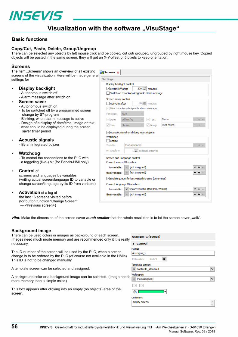
Visualization with the software „VisuStage“
Basic functions
Copy/Cut, Paste, Delete, Group/UngroupThere can be selected any objects by left mouse click and be copied/ cut out/ grouped/ ungrouped by right mouse key. Copied objects will be pasted in the same screen, they will get an X-Y-offset of 5 pixels to keep orientation.
ScreensThe item „Screens“ shows an overview of all existingscreens of the visualization. Here will be made generalsettings for
• Display backlight- Autonomous switch off - Alarm message after switch on
• Screen saver- Autonomous switch on- To be switched off by a programmed screen change by S7-program- Blinking, when alarm message is active- Design of a display of date/time, image or text, what should be displayed during the screen saver timer period
• Acoustic signals- By an integrated buzzer
• Watchdog - To control the connections to the PLC with a toggeling (live-) bit (for Panels-HMI only)
• Control of screens and languages by variables(writing actual screen/language ID to variable orchange screen/language by its ID from variable)
• Activation of a log of the last 16 screens visited before (for button function “Change Screen” → <Previous screen>)
Hint: Make the dimension of the screen saver much smaller that the whole resolution is to let the screen saver „walk“.
Background image There can be used colors or images as background of each screen.Images need much mode memory and are recommended only it it is reallynecessary.
The ID-number of the screen will be used by the PLC, when a screenchange is to be ordered by the PLC (of course not available in the HMIs)This ID is not to be changed manually.
A template screen can be selected and assigned.
A background color or a background image can be selected. (Image needsmore memory than a simple color.)
This box appears after clicking into an empty (no objects) area of thescreen.
56 INSEVIS Gesellschaft für industrielle Systemelektronik und Visualisierung mbH • Am Weichselgarten 7 • D-91058 ErlangenManual Software, Rev. 02 / 2018
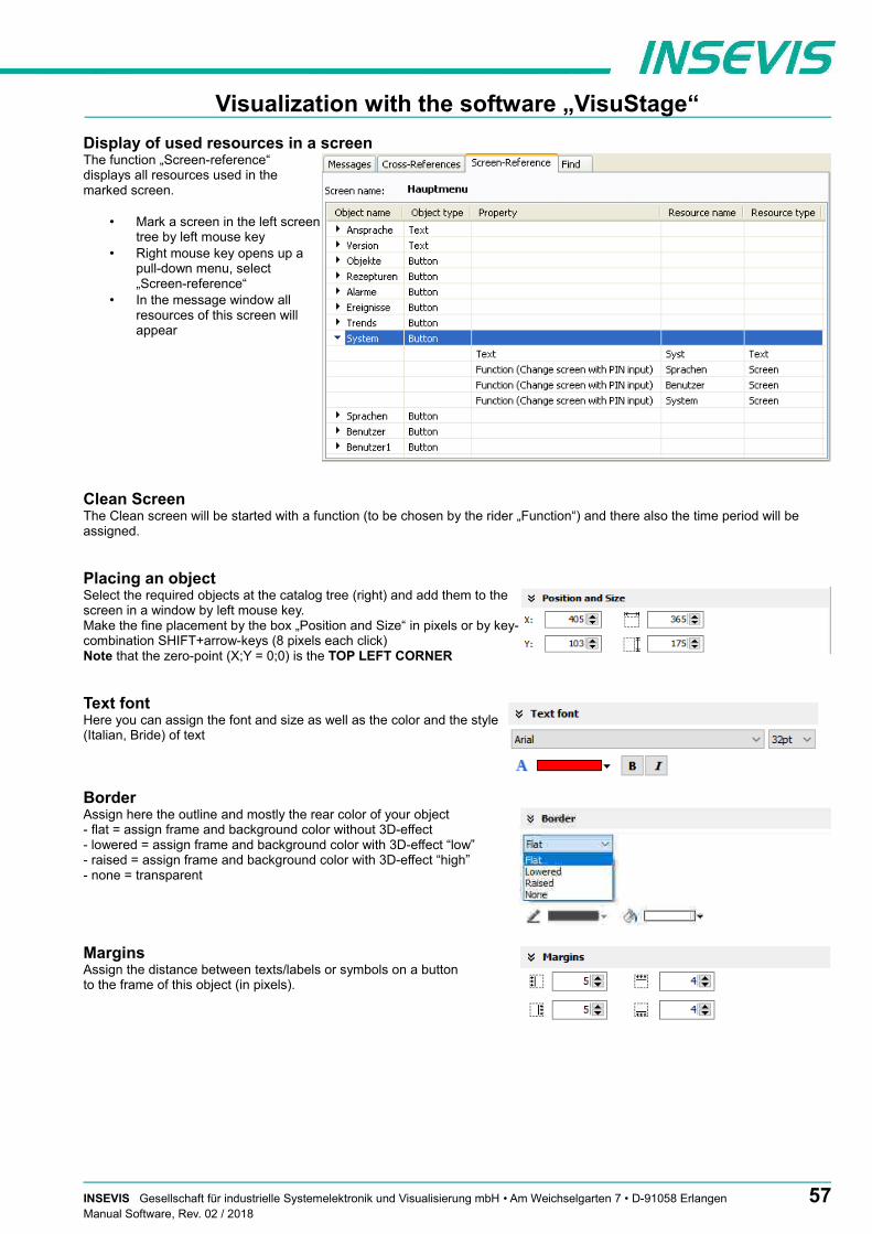
Visualization with the software „VisuStage“
Display of used resources in a screenThe function „Screen-reference“displays all resources used in themarked screen.
• Mark a screen in the left screentree by left mouse key
• Right mouse key opens up apull-down menu, select„Screen-reference“
• In the message window allresources of this screen willappear
Clean ScreenThe Clean screen will be started with a function (to be chosen by the rider „Function“) and there also the time period will be assigned.
Placing an objectSelect the required objects at the catalog tree (right) and add them to thescreen in a window by left mouse key. Make the fine placement by the box „Position and Size“ in pixels or by key-combination SHIFT+arrow-keys (8 pixels each click)Note that the zero-point (X;Y = 0;0) is the TOP LEFT CORNER
Text fontHere you can assign the font and size as well as the color and the style(Italian, Bride) of text
BorderAssign here the outline and mostly the rear color of your object- flat = assign frame and background color without 3D-effect- lowered = assign frame and background color with 3D-effect “low”- raised = assign frame and background color with 3D-effect “high”- none = transparent
MarginsAssign the distance between texts/labels or symbols on a button to the frame of this object (in pixels).
INSEVIS Gesellschaft für industrielle Systemelektronik und Visualisierung mbH • Am Weichselgarten 7 • D-91058 Erlangen 57Manual Software, Rev. 02 / 2018

Visualization with the software „VisuStage“
VisibilityThe visibility of objects can be controlled by a variable and is to be assigned easily
In this sample an object is hidden, In this sample an object is hidden, when the 4th bit (counting from right) when the variables value is between 4 and 6, will have the binary value 1, in all other cases it is visiblein all other cases it is visible
Hint: Depending on type of variables, some inputs can stay empty (e.g. the masking, if a boolean variable was selected).
Access rightsThese rights are to be assigned either by user level or by a variable.
In this sample an object is accessible, In this sample an object is accessible,for every user below the level 2 (Master) when the variables value is 1
Insert objectsObjects can be inserted by
• selecting in the right catalog window and clicking withleft mouse key in the menue window
• a key combination without mouse in the menue window (to see right beside the objectin the catalog-window)
• by right mouse key in the menue window by a popup window (see image right)
Group / Ungroup objectsGroup objects is necessary to fix multiple objects in an pre assigned position by the right mouse key.It makes sense e.g. to create library elements.
58 INSEVIS Gesellschaft für industrielle Systemelektronik und Visualisierung mbH • Am Weichselgarten 7 • D-91058 ErlangenManual Software, Rev. 02 / 2018

Visualization with the software „VisuStage“
The PLC can request what screen menu is active ad can force the VisuStage to change into another screen.
Query the current the screen ID number with SFC 200 "SCR_GET"
The currently shown screen ID number can be retrieved by using SFC 200 “SCR_GET“
Parameter Declaration Data type Description
LADDR INPUT WORD Logical base address = 0 (for all Panel-PLCs)Logical base address = 1...16 (connection-ID-No. to the Panel-HMI)
RET_VAL OUTPUT WORD Error codeW#16#0000 – No errorW#16#8002 – VisuStage is not running/configuredW#16#8xyy – General error codes (compatible to STEP®7)only for Panel-HMI: W#16#7000 – Job is in processW#16#7001 – Invalid connection state, e.g not connectedW#16#7002 – Job not accepted, because another job is proceeded actuallyW#16#7003 – Connection resource occupied (temporarily locked)W#16#8001 – Invalid connection ID number or connection is not configured
BUSY OUTPUT BOOL Busy flag, TRUE Job is in processing
SCREEN OUTPUT INT Currently shown screen ID number, (from VisuStage configured @ resources)
LANG OUTPUT INT Currently selected language ID number (referring to int´l. codes - you can find it in the csv-file, when using the text export)
S7-program sample for using the SFC200
Purpose: Query the actual screen
UN M 1500.0 // if read request is not set, then BEB // end the function
CALL SFC 200 LADDR :=W#16#0 // VisuStage connection ID number. // In Panel-PLC (e.g PC700P) must be W#16#0. RET_VAL:=MW1000 // Result / return code BUSY :=M1700.0 // TRUE = Reading is in process SCREEN :=MW2002 // Current screen ID number LANG :=MW2004 // Current language ID number
U M 1700.0 // Reading is in process BEB R M 1500.0 // reset request signal
L MW 1000 // return / result code L 0 // no error ==I // If no error, then BEB // end the function
L MW 1000 // error occurred // error evaluation // ...
BEA // end of function
INSEVIS Gesellschaft für industrielle Systemelektronik und Visualisierung mbH • Am Weichselgarten 7 • D-91058 Erlangen 59Manual Software, Rev. 02 / 2018

Visualization with the software „VisuStage“
Changing the screen with SFC 201 "SCR_SET"
Screen can be changed by using SFC 201 “SCR_SET“.
Parameter Declaration Data type Description
LADDR INPUT WORD Logical base address = 0 (for all Panel-PLCs)Logical base address = 1...16 (connection-ID-No. to the Panel-HMI)
SCREEN INPUT INT Screen ID number, (from VisuStage configured @ resources)
RET_VAL OUTPUT WORD Error codeW#16#0000 – No errorW#16#8002 – VisuStage is not running/configuredW#16#8003 – Invalid Screen ID numberW#16#8xyy – General error codes (compatible to STEP®7)
only for Panel-HMI: W#16#7000 – Job is in processW#16#7001 – Invalid connection state, e.g not connectedW#16#7002 – Job not accepted, because another job is proceeded actuallyW#16#7003 – Connection resource occupied (temporarily locked)W#16#8001 – Invalid connection ID number or connection is not configured
BUSY OUTPUT BOOL Busy flag, TRUE Job is in processing
S7-program sample for using the SFC201
Purpose: Change to screen with ID number 16917
UN M 1500.1 // if request is not set, then BEB // end the function
CALL SFC 201 LADDR :=W#16#0 // VisuStage connection ID number. // In Panel-PLC (e.g PC700P) must be W#16#0. SCREEN :=16917 // Screen ID number to change RET_VAL:=MW1000 // Return / result code BUSY :=M1700.1 // TRUE = Request is in process
U M 1700.1 // request is in process BEB R M 1500.1 // reset request signal
L MW 1000 // return / result code L 0 // no error ==I // if no error, then BEB // end the function
L MW 1000 // error occurred // error evaluation // ...
BEA // end of function
60 INSEVIS Gesellschaft für industrielle Systemelektronik und Visualisierung mbH • Am Weichselgarten 7 • D-91058 ErlangenManual Software, Rev. 02 / 2018

Visualization with the software „VisuStage“
Creating a visualization screen
Static objects
Lines, rectangles, texts, images
Images
Place an object: (see basic funtions)Assign visibility: (see basic funtions)Parameterize the object: (register “General”)• use an existing resource or create a new one directly here• in the „Stretch“-box choose „Fit to size“ to see your image in the objects rectangle
you did draw• assign horizontal/vertical orientation if object is not stretched• rotate and mirror object as you want to
Rectangles
Place an object: (see basic funtions)Assign visibility: (see basic funtions)Parameterize the object: (register “General”)• this sample shows a rectangle without border,
with a horizontal color gradient from red to green • all other properties are self explaining
Lines Place an object: (see basic funtions)Assign visibility: (see basic funtions)Parameterize the object: (register “General”)• this sample shows a 3px wide line.• When changing target screens a miss calculation of width can happen
what causes overlapping failure (reported in message window)
Texts
Place an object: (see basic funtions)Assign visibility: (see basic funtions)Assign text fonts: (see basic funtions)Parameterize the object: (register “General”)• Use an existing text resource or create a new one directly here OR
use the Internal system text to display compile-no and -date• Assign font, bride and italic style• Assign horizontal/vertical alignment• Check “Wrap words” if this is a multiline text
Color the object: (register „Appearance“):• Configure color changes by variables
- First field is the color of the text font- Second field is the background
Hint:
To change the background color, assign a FLAT BORDER for the text object.. Ifyou assign „NONE“, the background will be transparent and this can not becolored
General hints• static objecte may overlap each other• use PNG graphic format with a transparent Alpha-channel to let the background shine through the
transparent areas of the image (e.g. on rounded corners)
INSEVIS Gesellschaft für industrielle Systemelektronik und Visualisierung mbH • Am Weichselgarten 7 • D-91058 Erlangen 61Manual Software, Rev. 02 / 2018

Visualization with the software „VisuStage“
Dynamic objects
Date/Time fields
Date/Time fields are used to display (and, when „Editable“ is checked) to edit time and date by an automatic displayed virtual keyboard to type in the values.
Place an object: (see basic funtions)Assign visibility: (see basic funtions)Assign margins: (see basic funtions)Assign border: (see basic funtions)Assign font: (see basic funtions)Assign access rights: (see basic funtions)
Parameterize the object: (register “General”)• Assign the format of Date/Time field:
- Time format - Date format
• Assign horizontal and vertical alignment• By checking „Editable“ the object´s value is changeable
by the operator on the touch panel
General hints• If a DateTime field is to narrow, than characters, what can not be displayed completely will not displayed at all• dynamic objects shall not overlap each other (Exception: touch area may).• simulation with „ ► “ creates an error report, click on error and you come directly to the wrong object.• At TOD (TimeOfDay) the time will be displayed in hh:mm:ss format. Use TOD for longer times.• At TIME, S5TIME and TIMER time is displayed in ms Milliseconds).• At DATE the date will be displayed in days (since 01.01.1990).
62 INSEVIS Gesellschaft für industrielle Systemelektronik und Visualisierung mbH • Am Weichselgarten 7 • D-91058 ErlangenManual Software, Rev. 02 / 2018

Visualization with the software „VisuStage“
I/O fields
I/O fields are used to display (and, when „Editable“ is checked) to edit values with anautomatic displayed virtual keyboard to type in the values.
Place an object: (see basic funtions)Assign visibility: (see basic funtions)Assign margins: (see basic funtions)Assign border: (see basic funtions)Assign font: (see basic funtions)Assign access rights: (see basic funtions)
Parameterize the object: (register “General”)
• Assign the vertical and horizontal alignment
• Assign a (or create a new one) variable to be displayed in this field
• Assign the format of I/O-field - leading zero, „+“-sign, digits, decimal point- display format (if comma-key shall be used in keyboard dialog)- or use the format of the assigned variable (shown here)
• By checking „Editable“ the object´s value is changeable by the operator on the touchpanel
• Limit the max/min values (always depending on the variables type)
Notification of modificationAssign a bit to get informed, when the operator changes the value of the I/O-field at runtime.
Color the object: (register „Appearance“):
Assign a variable-based color change by entering• the required colors for
foreground (text color) andbackground (button color)
• the variable, what controls these color changes
General hints• At STRNG notice the S7-definitions (length-values in the first 2 bytes)! At INSEVIS the maximal length of the STRNG is 60 bytes BUT the referring DB MUST BE at least 60+2 bytes large!• Scaling: by S7-program with the Siemens-FC105 SCALE (Result: REAL-value, what is not allowed in VisuStage to color the appearance of this fields), • If this coloring/ appearance is needed, than us S7-commands Rounding (RND) or Cutting (TRUNC) to reach a valid value for this function• dynamic objects shall not overlap each other (Exception: touch area may).• simulation with „ ► “ creates an error report, click on error and you come directly to the wrong object.
INSEVIS Gesellschaft für industrielle Systemelektronik und Visualisierung mbH • Am Weichselgarten 7 • D-91058 Erlangen 63Manual Software, Rev. 02 / 2018

Visualization with the software „VisuStage“
PIN input fieldsIn the user administration can be assigned up to 9 levels with an up to 8-digit PIN- number to administrate the access rights.
A login-keyboard appears automatically after touching the PIN input field by the operator. „INPUT“ is to enter your PIN to get into your access rights.„CHANGE“ means, that PIN can be changed by authorized personally. After changing the new PIN is valid.
There are 3 ways to call this dialog:
1.) PIN-INPUT / CHANGE field (object)The benefit of this way is, that the target screens, whereto it will be changed aftersuccessfully login/ logout are defined in the resource „User“
And here can be assigned a special screen change too.
2a.) Invoke PIN-INPUT / CHANGE dialog (function)The benefit of this way is, that the login dialog can be assigned to any button or touch fieldas well.
The disadvantage is, that the screen is not automatically changeable with this function.
2b.) Change screen with PIN-input (function)This is the right way to assign a different screen to change for every single user level.
With assigning this function you need to design the target screens for every user level.
General hints• dynamic objects shall not overlap each other (Exception: A touch area may overlap other dynamic
objects).• Simulation with „ ► “ creates an error report, click on error and yo will be lead directly to the wrong
object.
64 INSEVIS Gesellschaft für industrielle Systemelektronik und Visualisierung mbH • Am Weichselgarten 7 • D-91058 ErlangenManual Software, Rev. 02 / 2018

Visualization with the software „VisuStage“
Diverse kinds of buttons
VisuStage contains standard, dynamic and text buttons. • Standard-buttons are available as templates and contain 65000 colors. • Dynamic buttons will be created in the VisuStage, contain 256 colors only but offer symbol change (by image list), multi
lingual text change (by text list) and color change functions. • Text buttons can proceed text changes with very large text lists
All buttons contain the dead-man´s function (executing the function too, when leave the button sidewards).
IMPORTANT HINT: If you execute a function wen PRESSING and LEAVING the button, it is hardly recommended to checkthis box! Otherwise it may happen, that the operator leaves the button sideways without executing theassigned function for leaving the button and e.g. an drive does go on instead of stopping.
Standard buttons
Place an object: (see basic funtions)Assign visibility: (see basic funtions)Assign margins: (see basic funtions)Assign font: (see basic funtions)Assign access rights: (see basic funtions)
Parameterize the object: (register “General”)• Check / uncheck the execution when leaving the button sideways
• Select a Label (Text) from your resources or import it directly here to place it on thebutton
• Select a Symbol from your resources or import it directly here to place it on thebutton
• Assign the place, where the image/symbol is displayed referring to the text
• Assign the size of the symbols image
Use of selfmade buttons• Copy your 3 buttons (all with the same name) each in one of those 3 directories
-\inactiv, -\pressed and -\unpressedof the main directory C:\Programs\INSEVIS\ VisuStage\Buttons.
• Choose the same color for the are in the middle, where your text and/or symbol will appear.
• Note: If you forward the source code of this VisuStage project (vsproj + vsbin) you need to add the 3 self made buttons and copy it in the same path like VisuStage Is installed there. Otherwise these buttons will not be displayed (and compiled to the binary).
INSEVIS Gesellschaft für industrielle Systemelektronik und Visualisierung mbH • Am Weichselgarten 7 • D-91058 Erlangen 65Manual Software, Rev. 02 / 2018

Visualization with the software „VisuStage“
Assign a function: (register “Function”)
It is possible to assign multiple functions to one action (press or release).
• Decide, WHEN the function will be proceeded:- at PUSHING or- at RELEASING the button
• After choosing a function (by double click) opens up another window to enter the required data for the selected function
• There can be assigned multiple functions to one object as well
• There can be assigned functions for pushing and releasing the button as well
Use of Soft-Key function• It is used to create own navigation buttons for viewer object and works in the same
screen as the viewer object is.
66 INSEVIS Gesellschaft für industrielle Systemelektronik und Visualisierung mbH • Am Weichselgarten 7 • D-91058 ErlangenManual Software, Rev. 02 / 2018

Visualization with the software „VisuStage“
Dynamic buttons
Place an object: (see basic funtions)Assign visibility: (see basic funtions)Assign margins: (see basic funtions)Assign font: (see basic funtions)Assign access rights: (see basic funtions)
Parameterize the object: (register “General”)
• Assign a variable, to control symbol- and text changes
• Text changes: (in the sample description / state of the buttons)choose (or create a new) atext list, what shell be shown on the dynamic button
• Symbol changes: (in the sample manually/automatic mode sign) choose (or create a new) an image list, what shell be shown on the dynamic button
Color the object: (register „Appearance“):
• Color changesfor foreground (text color) and background (for button color)
• Assign a variable to control color changes
ATTENTION: If there is active another value as these what are assigned in line 1...n, than ALWAYS this appearance will be displayed, what is assigned FIRST (in first line / line 1).
Use of self-made buttons• Dynamic buttons are to be created in the VisuStage software. • There is not possible to add additional (own) button designs.
Text buttons
These objects are used like a dynamic button without symbol change, but can be used to proceed very large text lists.
Touch areas – invisible buttons
These objects will be placed above an other object to add a special function by pressing it (like an invisible button).
Place an object: (see basic funtions)Assign access right: (see basic funtions)Assign a function: (register “Function”)
like at the simple buttons.
General hints• this dynamic object may overlap other dynamic objects• simulation with „ ► “ creates an error report, click on error and yo will be lead directly to the wrong object.
INSEVIS Gesellschaft für industrielle Systemelektronik und Visualisierung mbH • Am Weichselgarten 7 • D-91058 Erlangen 67Manual Software, Rev. 02 / 2018

Visualization with the software „VisuStage“
State areas
Place an object: (see basic funtions)Assign access rights: (see basic funtions)Assign visibility: (see basic funtions)
Parameterize the object: (register “General”)
• If you depend the state area on variables → use an existing resource or create a new one directly here
• If you use a system setting → select one of the system settings of the drop down menue
• In the „Stretch“-box choose - „Fit to size“ to see your image in the objects rectangle you did draw- “Proportional” to keep the images proportion (rest of the object stays empty)
• Assign an image resource or create a new one to be shown in ON-state and in OFF-state
General hints• dynamic objects shall not overlap each other (xeption: touch area).• use PNG graphic format with a transparent Alpha-channel to let the background shine through the
transparent areas of the image (e.g. on rounded corners).• using of similar graphic objects and less languages saves memory resources.• simulation with „ ► “ creates an error report, click on error and yo will be lead directly to the wrong
object.
68 INSEVIS Gesellschaft für industrielle Systemelektronik und Visualisierung mbH • Am Weichselgarten 7 • D-91058 ErlangenManual Software, Rev. 02 / 2018
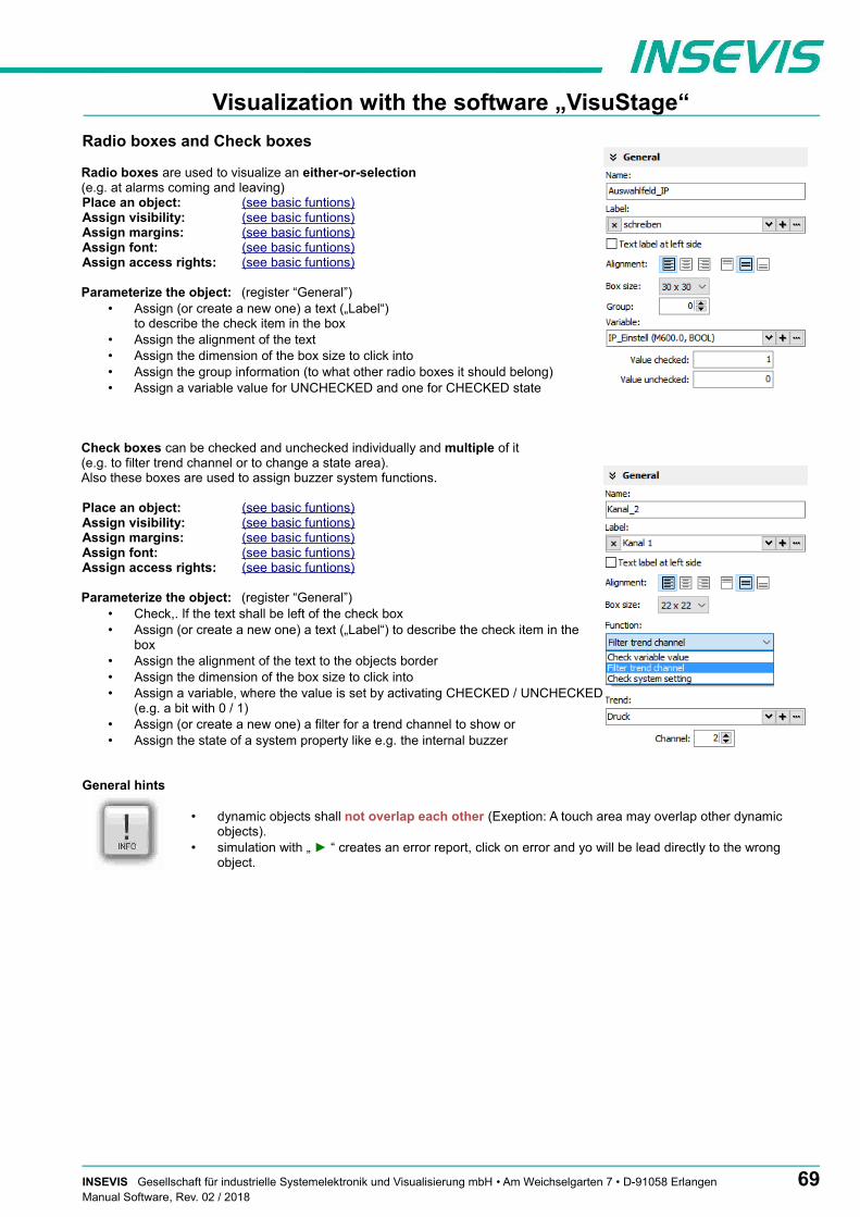
Visualization with the software „VisuStage“
Radio boxes and Check boxes
Radio boxes are used to visualize an either-or-selection(e.g. at alarms coming and leaving) Place an object: (see basic funtions)Assign visibility: (see basic funtions)Assign margins: (see basic funtions)Assign font: (see basic funtions)Assign access rights: (see basic funtions)
Parameterize the object: (register “General”)• Assign (or create a new one) a text („Label“)
to describe the check item in the box • Assign the alignment of the text• Assign the dimension of the box size to click into• Assign the group information (to what other radio boxes it should belong)• Assign a variable value for UNCHECKED and one for CHECKED state
Check boxes can be checked and unchecked individually and multiple of it (e.g. to filter trend channel or to change a state area). Also these boxes are used to assign buzzer system functions.
Place an object: (see basic funtions)Assign visibility: (see basic funtions)Assign margins: (see basic funtions)Assign font: (see basic funtions)Assign access rights: (see basic funtions)
Parameterize the object: (register “General”)• Check,. If the text shall be left of the check box• Assign (or create a new one) a text („Label“) to describe the check item in the
box • Assign the alignment of the text to the objects border• Assign the dimension of the box size to click into• Assign a variable, where the value is set by activating CHECKED / UNCHECKED
(e.g. a bit with 0 / 1)• Assign (or create a new one) a filter for a trend channel to show or• Assign the state of a system property like e.g. the internal buzzer
General hints
• dynamic objects shall not overlap each other (Exeption: A touch area may overlap other dynamic objects).
• simulation with „ ► “ creates an error report, click on error and yo will be lead directly to the wrong object.
INSEVIS Gesellschaft für industrielle Systemelektronik und Visualisierung mbH • Am Weichselgarten 7 • D-91058 Erlangen 69Manual Software, Rev. 02 / 2018

Visualization with the software „VisuStage“
Progress bars
This item is uses to display analog values like dimensions, time, etc.,where different colors depend on different limits assigned before.The progress bar right was designed with these settings below:
Place an object: (see basic funtions)Assign visibility: (see basic funtions)Assign margins: (see basic funtions)Assign font: (see basic funtions)Assign access rights: (see basic funtions)
Parameterize the object: (register “General”)• Assign a variable (or create a new one)
• Assign the format (minimal value, maximal value, decimal point)At INTEGER values type in the value w/o decimal point (here: 10000 = 1000.0)
• Assign a variable or a fixed value for Maxlimit and for Minlimit of the progress bar.
• If you want to color 3 parts of the progress bar, enable limit areas- by a fixed value or. By a variable
Color the object: (register „Appearance“)
• Choose a bar style (horizontal, vertical, 2D, 3D, color of background and fill color
• Decide, if the bar is always having ONE actual color (“Solid”) or 3 segments with a single color each (“Area”)
• If “Area” was selected: Assign direction of the colors in the bar
• Assign colors and of the 3 segments defined by the limits in “General”
• Design the ruler (position, color, divisions, capture height)→ at unfavourable divisions rounding errors are possible!
General hints
• dynamic objects shall not overlap each other (Exception: A touch area may overlap other dynamic objects)
• Simulation with „ ► “ creates an error report, click on error and yo will be lead directly to the wrong object
70 INSEVIS Gesellschaft für industrielle Systemelektronik und Visualisierung mbH • Am Weichselgarten 7 • D-91058 ErlangenManual Software, Rev. 02 / 2018

Visualization with the software „VisuStage“
Sliders
This object is a good solution to display a variables value along a staight line or (if editable is activated) to set up a value roughlyby hand.
Place an object: (see basic funtions)Assign visibility: (see basic funtions)Assign access rights: (see basic funtions)
Parameterize the object: (register “General”) • Assign a Variable vor the value you want to display/edit
• If “Changeable” is activated the slider point is movable and changes the variables value
• It is possible to assign the sliding rail by VisuStage or to import an existing image as Background image
• It is possible to assign the sliding point by VisuStage or to import an existing image as Slider point image
Parameterize the scale: (register “Ruler”) • Insert fixed values for the Minimum / Maximum of the rulers range
• Activate the display of the Ruler
• Select the rulers position referring the slider
• Assign the increments (values between the visible values on the ruler)
• Position = The rulers distance between the ruler and the sliding rail.
• Size = Width (at vertical) e.g. height (at horizontal) of the ruler
• Activate Scale sub marks (between the main marks = rulers increments)(it is better if these sub marks are a devisor of the main mark, e.g. 5 or 10, when therulers increment is 20)
• Activate Scale label (self explaining)
General hint:
By the dimension of the objects when putting into the menue by mouse it will be set automatically, if it is a • vertical (height > width) or an • horizontal (height > width)
slider.
INSEVIS Gesellschaft für industrielle Systemelektronik und Visualisierung mbH • Am Weichselgarten 7 • D-91058 Erlangen 71Manual Software, Rev. 02 / 2018

Visualization with the software „VisuStage“
System data (IP-address field, languages, etc.)
While languages, brightness or screen savers are functions what can be assigned to buttons or touch areas, the IP-address-field is an own object.
Place an object: (see basic funtions)Assign visibility: (see basic funtions)Assign margins: (see basic funtions)Assign font: (see basic funtions)Assign access rights: (see basic funtions)
Parameterize the object: (register “General”)
• Assign a (or create a new one) variable to control the system property
• By checking „Editable“ the object´s value is changable by the operator on the touchpanel
• Assign the alignment of the box
Color the object: (register „Appearance“)
• If the field and text colors should change by variables value (e.g. „Disabled-Look“ and „Enabled-Look“)
General hints:
• this function needs a S7-program with a SFC to run.• dynamic objects shall not overlap each other (Exception: A touch area may overlap other dynamic
objects).• simulation with „ ► “ creates an error report, click on error and yo will be lead directly to the wrong
object.
72 INSEVIS Gesellschaft für industrielle Systemelektronik und Visualisierung mbH • Am Weichselgarten 7 • D-91058 ErlangenManual Software, Rev. 02 / 2018

Visualization with the software „VisuStage“
Gauges
With this object a value can displayed in a gauge form with a pointer like in older meters.
Place an object: (see basic funtions)Assign visibility: (see basic funtions)
Parameterize the object: (register “General”)• Assign a variable to display their value• Activate a background image
(If you do not want do create your gauge by VisuStage)
Parameterize the dial: (register “Dial”)When round dial is activated, a circle is created by the smaller value ox X and Y• When “Show dial” is activated this can be colored
- Assign the background color of the dial- Assign the border color and thickness of the dial
• When “Round dial” is dectivated, you can set:- Radius of the circle segment (angle below „Scale“)- X-Position of the pointer rotation points (from the left object border)- Y-Position of the pointer rotation points (from the upper object border)
Scale configuration: (register “Scale”)• Insert Minimum / Maximum of the scale value to be dislayed
• Insert the Angle of the circle segment for the scale area- Start at Min, end at Max, - Pointer always runs clockwise- Information angle position: -270° = „6 o´clock“ / -180° = „9 o´clock“ -90° = „12 o´clock“ / 0° = „3 o´clock“ / 90° = „6 o´clock“ 180° = „9 o´clock“ / 270° = „12 o´clock“
• Activate Scale marks (marks and sub marks)- Increments between main marks- Color, thickness, position (~Radius form pointer rotation point), size (~length)
• Activate Scal sub marks- Increments between sub marks- Color, thickness, position (~Radius of the pointer rotation point), size (~length)
• Activate Scale label- Font, size, color, style (bride/italian)- Position (~ assign radius of the pointer rotation point
Pointer configuration: (register “Pointer”)• Assign a color for the pointer• Assign the length of the pointer (distance between pointer root to top))• Assign the width of the pointer • Design the shape of the pointers tip (0,01~ flat, >0,01 more and more narrow)• Assign the distance between pointer root to the rotation point (tail)• Color the circle at the pointers rotation point
(The rotation circle always does have a 1 pixel-frame outside in the pointers color) )• Adjust the size (diameter) of the rotations points circle
INSEVIS Gesellschaft für industrielle Systemelektronik und Visualisierung mbH • Am Weichselgarten 7 • D-91058 Erlangen 73Manual Software, Rev. 02 / 2018

Visualization with the software „VisuStage“
Configure the color ring: (register „Range“)Limits and areas can be colored by a ring inside/outside the scale.
• Activate Scale range- Assign the position (~ radius of this circle segment)- Assign the thickness of this ring
• Coloring- The color area do not have an upper limit.- The next color are starts at the lower limit of the next color. - the last color limit is the maximum limit of the scale
General hints:
• this function needs a S7-program with a SFC to run.• dynamic objects shall not overlap each other (Exception: A touch area may overlap other dynamic
objects).• simulation with „ ► “ creates an error report, click on error and yo will be lead directly to the wrong
object.
74 INSEVIS Gesellschaft für industrielle Systemelektronik und Visualisierung mbH • Am Weichselgarten 7 • D-91058 ErlangenManual Software, Rev. 02 / 2018

Visualization with the software „VisuStage“
Viewers
Image and text lists
Image list sample with color change of the pipes. The pipes will be separated into segments. For these segments all colors are available as single images with the requested colors. In the resource „image list“ values will be assigned to these single images. In the object image list these values will be controlled by a variable (what itself is controlled by arrow buttons, what increase/decrease its value by „1“. This value is also shown in a I/O-field).
Place an object: (see basic funtions)Assign visibility: (see basic funtions)
Parameterize the object: (register “General”)• Ín the „Stretch“-box choose „Fit to size“ to see your image in the objects rectangle
you did draw• Assign horizontal/vertical orientation if object is not stretched• Rotate and mirror object as you want to assign an image list resource
(must be existing - created at the image lists item) • Assign a variable, what controls the image lists value
Text list sample with displaying the actual logged-in user. There were assigned 3 user (user 1, .._2, .._3).
Place an object: (see basic funtions)Assign visibility: (see basic funtions)
Parameterize the object: (register “General”)• In the „Stretch“-box choose „Fit to size“ to see your image in the objects rectangle
you did draw• Assign horizontal/vertical orientation if object is not stretched• Rotate and mirror object as you want to assign an image list resource
(must be existing - created at the image lists item) • Assign a variable, what controls the image lists value
Color the object: (register „Appearance“):
Additional functions at text lists• If there is a multiline text list, it is possible to assign
navigation buttons for scrolling up-/down
Assign the color: (register “Appearance”)
• Color changesfor foreground (text color) and background (for button color)
• Assign a variable to control color changes
General hints:
• this function needs a S7-program with a SFC to run.• dynamic objects shall not overlap each other (Exception: A touch area may overlap other dynamic
objects).• simulation with „ ► “ creates an error report, click on error and yo will be lead directly to the wrong
object.
INSEVIS Gesellschaft für industrielle Systemelektronik und Visualisierung mbH • Am Weichselgarten 7 • D-91058 Erlangen 75Manual Software, Rev. 02 / 2018

Visualization with the software „VisuStage“
Message viewing and archiving
There are different objects to display messages:• blinking symbols (Message indicator)• blinking text lines (Message indicator - text)• oldest/youngest message only (Message viewer - line)• viewer box for all actual messages (Message viewer - multi line)• viewer for all archived messages (Message archive viewer)
Message indicator symbol and textThis dynamic objects are used to inform the operator about an actual existing message (alarms/events) either with a blinking symbol or a blinking text line.
Indicator at alarms: Blinking if alarm has come and is not acknowledgedDisplay (without blinking) if alarm is acknowledge but still thereDisappears if alarm is acknowledged and no more there
Indicator at events: Blinking if event is thereDisappears if event is no more there
Placing as like at all other objects too, Parameterization is self explaining only Assign an event type - alarm or message.
Message viewer - lineThis message line is made to show only the most actual message to be implemented as an information line only, with no opportunity to acknowledge or scroll.
Place an object: (see basic funtions)Assign visibility: (see basic funtions)
Parameterize the object: (register “General”)
• Select “events” or ”alarms” to display• Adjust, if oldest or newest message will be displayed• Activate word wrapping
Formatting the object (register “Message format”)• date• time• state• ID-no. (Group)• message text
Color the object (register „Appearance“)All messages in the message viewers all single messages can be changed in colorreferring to their stat (Coming, Going, Acknowledged).
76 INSEVIS Gesellschaft für industrielle Systemelektronik und Visualisierung mbH • Am Weichselgarten 7 • D-91058 ErlangenManual Software, Rev. 02 / 2018

Visualization with the software „VisuStage“
Message viewer multiline
This message viewer is made to show all active messages. It contains navigation functions (line scroll) and (for alarms) an acknowledgment function.
Place an object: (see basic funtions)Assign visibility: (see basic funtions)Formatting the object: (register “Message format” at the single line message viewer)Color the object: (register „Appearance“ at the single line message viewer)
Parameterize the object: (register “General”)
• Select “events” or ”alarms” to display• Adjust, if oldest or newest message will be displayed• Activate word wrapping
Formatting navigation bar: (register “Navigation bar”)• Activate the bar• Color the background• Design the placement of the buttons • Configure the size of the icons in the buttons• Select a button template• Design the button size width by height• Adjust the distance between the buttons
Designing navigation buttons: (register “Navigation buttons”)• Select a button template• Activate to insert a icon (Up/Down/Acknowledge)• Select one of the icons from the list
Message archive viewer
This message viewer is made to show all archived messages. It contains navigation functions (line and page scroll).
Place an object: (see basic funtions)Assign visibility: (see basic funtions)Formatting the object: (register “Message format” at the single line message viewer)Color the object (register „Appearance“ at the single line message viewer)Formatting navigation bar: (register “Navigation bar” at the multiline message viewer)
Designing navigation buttons: (register “Navigation buttons”)It is also like at the multiline viewer, but there are other buttons.
• No ACKnowledgement (because this is an archive)• But GoTo START/END to reach the first/last archive value.
INSEVIS Gesellschaft für industrielle Systemelektronik und Visualisierung mbH • Am Weichselgarten 7 • D-91058 Erlangen 77Manual Software, Rev. 02 / 2018
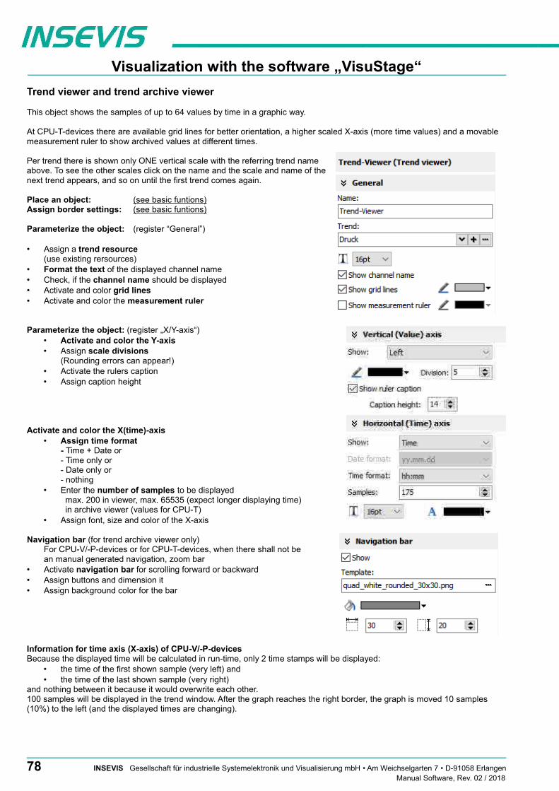
Visualization with the software „VisuStage“
Trend viewer and trend archive viewer
This object shows the samples of up to 64 values by time in a graphic way.
At CPU-T-devices there are available grid lines for better orientation, a higher scaled X-axis (more time values) and a movable measurement ruler to show archived values at different times.
Per trend there is shown only ONE vertical scale with the referring trend nameabove. To see the other scales click on the name and the scale and name of thenext trend appears, and so on until the first trend comes again.
Place an object: (see basic funtions)Assign border settings: (see basic funtions)
Parameterize the object: (register “General”)
• Assign a trend resource(use existing rersources)
• Format the text of the displayed channel name• Check, if the channel name should be displayed• Activate and color grid lines• Activate and color the measurement ruler
Parameterize the object: (register „X/Y-axis“)• Activate and color the Y-axis• Assign scale divisions
(Rounding errors can appear!)• Activate the rulers caption• Assign caption height
Activate and color the X(time)-axis• Assign time format
- Time + Date or- Time only or- Date only or- nothing
• Enter the number of samples to be displayed max. 200 in viewer, max. 65535 (expect longer displaying time) in archive viewer (values for CPU-T)
• Assign font, size and color of the X-axis
Navigation bar (for trend archive viewer only)For CPU-V/-P-devices or for CPU-T-devices, when there shall not bean manual generated navigation, zoom bar
• Activate navigation bar for scrolling forward or backward• Assign buttons and dimension it• Assign background color for the bar
Information for time axis (X-axis) of CPU-V/-P-devicesBecause the displayed time will be calculated in run-time, only 2 time stamps will be displayed:
• the time of the first shown sample (very left) and • the time of the last shown sample (very right)
and nothing between it because it would overwrite each other.100 samples will be displayed in the trend window. After the graph reaches the right border, the graph is moved 10 samples (10%) to the left (and the displayed times are changing).
78 INSEVIS Gesellschaft für industrielle Systemelektronik und Visualisierung mbH • Am Weichselgarten 7 • D-91058 ErlangenManual Software, Rev. 02 / 2018

Visualization with the software „VisuStage“
Sample Trend viewer from sample visualization
Activating trend channel: by check box (function: Filter trend channel)Display the actual sample value: by I/O-field (variables value)Zoom in/out functions: as button function (Trend viewer function, zoom in/out)
Sample Trend viewer from sample visualization
Activating trend channel: by check box (function: filter trend channel)Zoom in/out functions: as button function (trend archive viewer function, zoom in/out)
Manually designed navigationFirst / last (actual) samples as button function (trend viewer function, zoom in/out)Next sample page / sample page before as button function (trend viewer function, zoom in/out)Values at the measurement ruler time as I/O-field (with values from trend archive viewer)Move the m-ruler to a certain time as date/time-field (with source trend archive viewer)(The measurement ruler can be movedby touching the touch display in the viewer)
General hints• trends can be archived only, if there is a micro-SD-card inserted• for CPU-V/-P-devices:
trend viewer max. 100 samples will be displayed. When the samples reach the right border, they were shifted 10% to the left trend archive viewer: max. 800 samples can be displayed
• for the CPU-T-devicestrend viewer: max 1000 samples can be displayed. When the last sample reaches the right border,the where shifted to left pixel by pixel.Trend archive viewer: max. 655.350 samples can be archived (=10 circular archives)
• there is shown only ONE vertical scale with the referring trend name above. To see the other scales click on the name and the scale and name of the next trend appears... until the first trend comes again.• dynamic objects shall not overlap each other (Exception: A touch area may overlap other dynamic
objects).• simulation with „ ► “ creates an error report, click on error and yo will be lead directly to the wrong object.
INSEVIS Gesellschaft für industrielle Systemelektronik und Visualisierung mbH • Am Weichselgarten 7 • D-91058 Erlangen 79Manual Software, Rev. 02 / 2018

Visualization with the software „VisuStage“
Recipe viewer
The resource “recipes” will displayed by this object in 3 different windows:• Recipe viewer window• Records viewer window (of each recipe)• Element configuration window
Place an object: (see basic funtions)Assign border settings: (see basic funtions)Assign access right: (see basic funtions)
Parameterize the object: (register “General”)Name:
• internal name of the recipe viewer (independent of project language)
Show only one recipe: • reduces the list to only one (selected) recipe (e.g. if this machine is designed for
only one recipe but the project contains more recipes for more machines)Recipe variable: (to display the actual used receipt name)
• Assign it, if the internal number of the recipe shall be stored in a S7-variable,what will be linked with the receipt name
• (resource „View Name“ in a text list and can be displayed as active receipt name)Record variable: (to display the actual used receipt name)
• Assign it, if the internal number of the record shall be stored in a S7-variable tobe shown in a I/O-field to display the actual record name
• (At first simulation assign any value to this variable in the SimuStage, than yousee the active record after press the button „Save to PLC“)
Enable to edit the recipe: • Allows manipulation by the operator (changing the element values, storing as a
new record, deleting records and so on)
Parameterization of the title bar (general for recipe lists, record lists, element lists)
• It is recommended to use a title bar and to assign a title to the recipe list.
• The titles of the other lists bellow (record list and element list) will be assignedautomatically by the inserted data.
• (Title of the record list in the sample „red shades“, element list in the sample Rose“)
• All other settings are self explaining settings to design the title bar
Parameterization of the navigation bar (general for recipe lists, record lists, element lists)
• This activation is recommended, when more recipes, records or elements are usedthan fit into the screen window and scrolling is necessary.
• All settings are self explaining settings to design the scroll bar
General hintInstead of a navigation bar you can assign own buttons by using“Receipe Viewer Function” at releasing the button.
80 INSEVIS Gesellschaft für industrielle Systemelektronik und Visualisierung mbH • Am Weichselgarten 7 • D-91058 ErlangenManual Software, Rev. 02 / 2018

Visualization with the software „VisuStage“
Parameterization of the operators control elements (general for recipe lists, record lists, element lists)
By the register „Navigation buttons“ can be selected all function keys you need.Their button design can be substituted by a customized button.
Recipe list:Select: activates a recipe from the recipe list (will be highlighted),
by touching directly too, this list can be hided, when you have1 receipe only
Record list:Select: activates a record from the record list (will be highlighted),
by touching directly too
New: creates a new record with existing element structure
Save as: saves the record with a new name in the Micro-SD-card (an string input field opens automatically)
Delete: deletes an existing record
Copy: copies an existing record
Back: returns to recipe list
Element list:Edit opens up a virtual keyboard to edit the elements value
Save: overwrites (in the Micro-SD-card) an existing value with actual element values
To PLC: transfers the stored values and records into the PLC
From PLC: reads variable for element values from the PLC
Back: returns to record list
Assign a width of the recipe viewers window to the displayed elements name to have aefficient window design.
Different confirmation messages (register “Messages”)
In the 3 different viewing windows (recipe, record- and element-) it is useful to ask the usere“Do you really want to...?” BEFORE he is manipulating something wrong.These message texts are system messages and can be activated here
At the text resources you will find these text phrases as system texts always on top of thetexts and in the csv-file with the prefix „__SYSTEXT“.
These messages will be displayed BEFORE storing, deleting, data transfer to/from PLC
(These register is shown just for the record-list only, the others work similar to it.)
INSEVIS Gesellschaft für industrielle Systemelektronik und Visualisierung mbH • Am Weichselgarten 7 • D-91058 Erlangen 81Manual Software, Rev. 02 / 2018

Visualization with the software „VisuStage“
Views of recipe lists, record lists, element lists at runtime
Recipe list
The recipe list contains all recipes, what are pre-assigned in theVisuStage before. It has an clear and an uniform element structure,what was pre-assigned in the software VisuStage before.
The assigned name for all recipes is displayed on the title list.
The choice of the a recipe is done by a touch on the name and atouch on the bottom left symbol to open it. Than the display changesinto the next screen with the record list.
To exit the recipe administration, add a common button and assignthe function „change screen“ whereto ever you want.
Record list
The record list contains all user-created records of a certain recipe(in this sample of the recipe „red colors“).
The regarding recipe name is displayed on the title list. Select it bytouch on the name and press „Edit“ or create a new one. Than itswitches directly into the element table to edit values and to store itin an automatically displayed string input field.
New from VS 2.0.1.5: The actual record will be displayed in the color of the recipes name in the title bar
The function buttons are displayed in the lower left bar:Edit | New | Save | DeleteWith the lower right „←“ this screen changes back to the recipe list.
Note: Because recipe data are kept in the Micro-SD-card there ispossible no simulation with these values (your PC has not such amemory extension).
Element list
The element list contains all user-created values of a certain record(in this sample of the record „ROSE_1“)
The regarding record name is displayed on the title list.
By touching an elements value a numeric keyboard opens upautomatically to type in the new value of the selected element.
The function buttons are displayed in the lower left bar:Edit | Save | Read from PLC | Write to PLCWith the lower right „←“ this screen changes back to the record list.
Note: Because recipe data are kept in the Micro-SD-card there ispossible no simulation with these values (your PC has not such amemory extension).
82 INSEVIS Gesellschaft für industrielle Systemelektronik und Visualisierung mbH • Am Weichselgarten 7 • D-91058 ErlangenManual Software, Rev. 02 / 2018
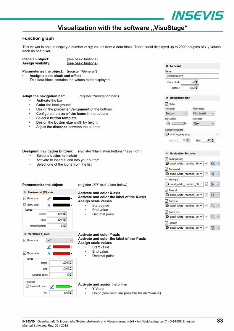
Visualization with the software „VisuStage“
Function graph
This viewer is able to display a number of x;y-values from a data block. There could displayed up to 2000 couples of x;y-values each as one pixel.
Place an object: (see basic funtions)Assign visibility: (see basic funtions)
Parameterize the object: (register “General”)• Assign a data block and offset
This data block contains the values to be displayed
Adapt the navigation bar: (register “Navigation bar”)• Activate the bar• Color the background• Design the placement/alignment of the buttons • Configure the size of the icons in the buttons• Select a button template• Design the button size width by height• Adjust the distance between the buttons
Designing navigation buttons: (register “Navigation buttons” / see right)• Select a button template• Activate to insert a icon into your buttom• Select one of the icons from the list
Parameterize the object: (register „X/Y-axis“ / see below)
Activate and color X-axisActivate and color the label of the X-axisAssign scale values
• Start value• End value• Decimal point
Activate and color Y-axisActivate and color the label of the Y-axisAssign scale values
• Start value• End value• Decimal point
Activate and assign help line• Y-Value• Color (one help line possible for an Y-value)
INSEVIS Gesellschaft für industrielle Systemelektronik und Visualisierung mbH • Am Weichselgarten 7 • D-91058 Erlangen 83Manual Software, Rev. 02 / 2018
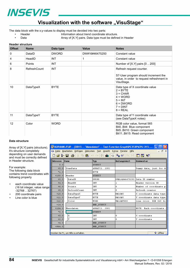
Visualization with the software „VisuStage“
The data block with the x;y-values to display must be devided into two parts:• Header Information about trend coordinate structure.• Data Array of [X,Y] pairs. Data type must be defined in Header
Header structure
Offset Name Data type Value Notes
0 DataID DWORD DW#16#46475250 Constant value
4 HeadID INT 1 Constant value
6 Points INT Number of [X,Y] pairs [0 .. 200]
8 RefreshCount INT Refresh request counter.
S7-User program should increment the value, in order to request refreshment in VisuStage.
10 DataTypeX BYTE Data type of X coordinate value2 = BYTE3 = CHAR4 = WORD5 = INT6 = DWORD7 = DINT8 = REAL
11 DataTypeY BYTE Data type of Y coordinate value(see DataTypeX notes)
12 Color WORD RGB color value, format 565Bit0..Bit4 Blue componentBit5..Bit10: Green componentBit11..Bit15: Read component
Data structure
Array of [X,Y] pairs (structure).It's structure completelydepending on user demandsand must be correctly definedin Header structure.
For example: The following data blockcontains trend coordinates withfollowing property
• each coordinate value (16 bit integer, value range-32768 .. 32767)
• 200 coordinate pairs• Line color is blue
84 INSEVIS Gesellschaft für industrielle Systemelektronik und Visualisierung mbH • Am Weichselgarten 7 • D-91058 ErlangenManual Software, Rev. 02 / 2018

Visualization with the software „VisuStage“
Working with library elements
Library elements were used to have available pre assigned elements for different projects. This is very useful as base for multiple visualizations and show a corporate design e.g. at navigation bars, state bars and login pages.
Creating libraries and ~ elements
Single or multiple (grouped or ungrouped)objects can be added to a library, consisting ofat least one element. If a library element consists of multiple objects,it is better to group these objects before. Sothe positions between these objects are fixed.
To create a new library• 1. select the "new library" button• 2. assign name, path and comments• 3. select the new created library and• 4. open this new library
To add new library elements• 1. open your library• 2. move objects or groups directly
on the library sign
Using library elements
Activate library window at the menue VIEW → LIBRARY.
The Library function is self explaining:• either CREATE a new one,• or ADD another library from any PC-directory (*.vsl) into this library list• or OPEN a library from this list
Group some objects and name the group. Copy this group by drag´n drop into your open library orClick at a group in your open library and copy it by drag´n drop into your screen.
These properties will be taken over 1:1 from the library element into the new screen/project:• Variables, • Texts and • Images
All other resources must be assigned new. Library elements will be integrated in the visualization project (*.vsproj).To send your libraries to others, always zip and send complete libraries (folders on the VisuStage-PC) including your library elements (*.vsl) .
INSEVIS Gesellschaft für industrielle Systemelektronik und Visualisierung mbH • Am Weichselgarten 7 • D-91058 Erlangen 85Manual Software, Rev. 02 / 2018

Visualization with the software „VisuStage“
Simulation and download
Error treatment
• After finishing the visualization start the simulation by F9 or „►“• If there are errors, the compiler stops and creates a error message (object and error type).• Double click this message and you will see the failed object.• Correct the error and restart the simulation by „F9“ or „►“
If all errors are cleared, the compiler creates a *.bin-file and the simulation tool „SimuStage“ starts automatically.
General hint• The error message area will be closed by pressing „F6“
86 INSEVIS Gesellschaft für industrielle Systemelektronik und Visualisierung mbH • Am Weichselgarten 7 • D-91058 ErlangenManual Software, Rev. 02 / 2018

Visualization with the software „VisuStage“
Simulation and download
There are 2 ways to simulate your visualization:
Manual simulationStarts the integrated simulation tool SimuStage in a new window. The operation by the user is by mouse pointer simulated like at the real touch panel.
Automatical simulationStarts the SimuStage together with the Siemens-software S7-PLCSIM (what must be installed at the same PC). The process data come from S7-PLCSIM (not from PLCSIM Advanced – this is for 1200/1500CPUs). Of course, S7-PLCSIM does not simulate INSEVIS-SFCs/SFBs.
Manual simulation
By manipulating variable values in thevariable table you can cause changesmanually.
Events can be simulated (Coming -Leaving - Acknowledge) bychecking/unchecking boxes in theSimuStage.
It is also possible to generate screen shotsof the simulated screen for creating anykind of documentation.
Automatical simulation
Start in the VisuStage by “Project” → “Simulate with S7-PLCSIM”
The (already installed) S7-PLCSIM must beopened from the S7-programming tool.
Here you find the call from SimaticManager
1. select “Blocks”
2. click on “Simulate modules”
INSEVIS Gesellschaft für industrielle Systemelektronik und Visualisierung mbH • Am Weichselgarten 7 • D-91058 Erlangen 87Manual Software, Rev. 02 / 2018

Visualization with the software „VisuStage“
Here you find the call from SimaticManager
1. Goto “Device configuration”2. Select “Device view”3. Select the CPU4. select “Simulation” and “Start”
If the S7-PLCSIM was called, the S7 program is simulated ONCE only, for cyclic simulation use the right button (green frame)
To transfer the project (start by key F12 or icon) use the IP-target-address from the project data or the IP-addresses in the network area you are connected to.
General Hint• If some devices with the same IP-address should be connected, this will be stopped from Windows-OS. To
switch off this function, please insert in the cmd this command: arp -d (this deletes in your PC the old MAC-address from the foregoing device, what was stored in your PC).
88 INSEVIS Gesellschaft für industrielle Systemelektronik und Visualisierung mbH • Am Weichselgarten 7 • D-91058 ErlangenManual Software, Rev. 02 / 2018

Remote access with the software „RemoteStage“
GeneralThe RemoteStage is a multiple instanciable software, what not needs to be installed from version 1.0.3.3 any more. It can be kept in a folder on the remote-PC or on a mobile data carrier as remotestage.exe (and if you use German program language with the file remotestage.deu as well).
The software RemoteStage uses the binary files (binaries / *.vsbin) of visualization projects, made with „VisuStage“. These binaries are not backreadable, what offers an effective protection of the useres know-how and allows to forward these files towards the final user or operator.
With version 1.0.4.0 it is possible to download the visualization binary directly by Ethernet from the Panel-PLC / Panel-HMI (See right button). This helps to reduce the organization effords by far. In VisuStage youmay assign a PIN-code to protect your visualization against unauthorized uploads.
The RemoteStage works like an additional Panel-HMI on the remote-PC, what gets the process (actual) data by a TCP/IP-connection straight from the PLC. System data like Time and Buzzer are related to even this PC of course.
This allows a remote visualization and account to external S7-PLCs as well. This is a function nearly similar to WinCC runtime of a remote PC)
If the RemoteStage should be installed as an batch call on the end user´s PC this is all you need to write:
[path of RemoteStage]\remotestage.exe /r=[IP-address of the remote-PLC in the same sub net]/V=[path of visualization binary]\complete file name]/start
Selection of the remote-device
With opening of the visualization binary ( „visualization“.vsbin) the IP-address ofthe remote PLC will be required (Fig.).
(By using the function „accessible devices“ - loupe- you can select one of thesedirectly or type in the IP-address manually.)
This address will be linked with this binary. So it is not necessary to re-type itagain.
INSEVIS Gesellschaft für industrielle Systemelektronik und Visualisierung mbH • Am Weichselgarten 7 • D-91058 Erlangen 89Manual Software, Rev. 02 / 2018

Remote access with the software „RemoteStage“
Using and setting up the remote screen
The PopUp-menues are self explaining. The actual remote state is shown on the bottom of the screen.
Yellow: connecting (set up connection)Green: connected (online) and PLC in RUNRed: connected (online) and PLC in STOP
The switching between online/offline can be done by the greenbutton beside the IP-address line or by the menu „PLC“.
Hint: Referring the system data (like buzzer, archives and time) always the PC-system data will be used, not these of the remote device.
Storing the remote (on the PC) archived data
The archive data, logged during the remote session on the PC, will be stored on theworking place in the remote-PC only. (not depending from the archive in the PLC in theMicro-SD-card during the same time).
Note: there are 2 archives of each item. If you want to archive a remote-trend, you needto start this trend in the remote visualization.
At the menu „Settings“ will be set up, if these date will be stored - in the project folder (where the visualization binary is kept) or - at another path.
Converting archive data into csv-files
These data can be archived by these products on the Micro-SD-card:Messages (alarms, events) by all Panel-PLCs and Panel-HMIs
→ by activating the archive funtion „archiving“ in the VisuStage-projectTrends (with all channels) by all Panel-PLCs and Panel-HMIs
→ by activating the archive funtion „archiving“ in the VisuStage-projectRecipes (with all records) by all Panel-PLCs and Panel-HMIs
→ will always be stored / archived on the Micro-SD-cardArchiv-(data blocks) by all Panel-PLCs and Panel-HMIs
→ will be configured by SFCs in the S7-program
Most of the data is stored as a binary on the Micro-SD-card and can be converted into csv-format by theRemoteStage only. Therefore you may open a special data converting mode within the RemoteStage program by this icon (right).
CAUTION: Always open the binary suiting to your visualization on the remote device, or upload it as binary!
In the newly appeared PC-window you may find different groups of icons with different functions:
Displays archive by- Read in the archives over Ethernet Export / save the archive datainserting the Micro-SD- by IP-address directly into PC to thePC / into the PC-networkcard in PC-card slot left->right: - Alarm archive left->right: - Alarm archiveleft->right - Alarm archive - Event archive - Event archive - Event archive - Trend archive - Trend archive
- Trend archive - Recipe archive - Recipe archive- Data(DB-)archive - Data(DB-)archive
90 INSEVIS Gesellschaft für industrielle Systemelektronik und Visualisierung mbH • Am Weichselgarten 7 • D-91058 ErlangenManual Software, Rev. 02 / 2018

Remote access with the software „RemoteStage“
Sample for message archive viewer and csv-exportBelow: View of the event archive in the RemoteStage Below: Export of the event archive as csv-file
(Displays all archived alarm messages of the Panel-PLC / Panel-HMI with the IP-address 192.168.80.50)
CAUTION:Do not confuse the uploaded (from Micro-SD-card) archive file withthe other archive file created during the remote-session in theremote-PC itself. Pay attention to format the csv-file according to your own needs.
Sample for trend archive viewer and csv-export
Below: View of the trend „Druck“ archive in the RemoteStage
Above figure displays all archived trend with name „Druck“of the Panel-PLC / Panel-HMI with the IP-address 192.168.80.30. The time will be displayed in the Language format you assigned on your PC (here in German = DE)
CAUTION:Do not confuse the uploaded (from Micro-SD-card) archive file with the other archive file created during the remote-session in the remote-PC itself. Pay attention to format the csv-file according to your own needs.
INSEVIS Gesellschaft für industrielle Systemelektronik und Visualisierung mbH • Am Weichselgarten 7 • D-91058 Erlangen 91Manual Software, Rev. 02 / 2018
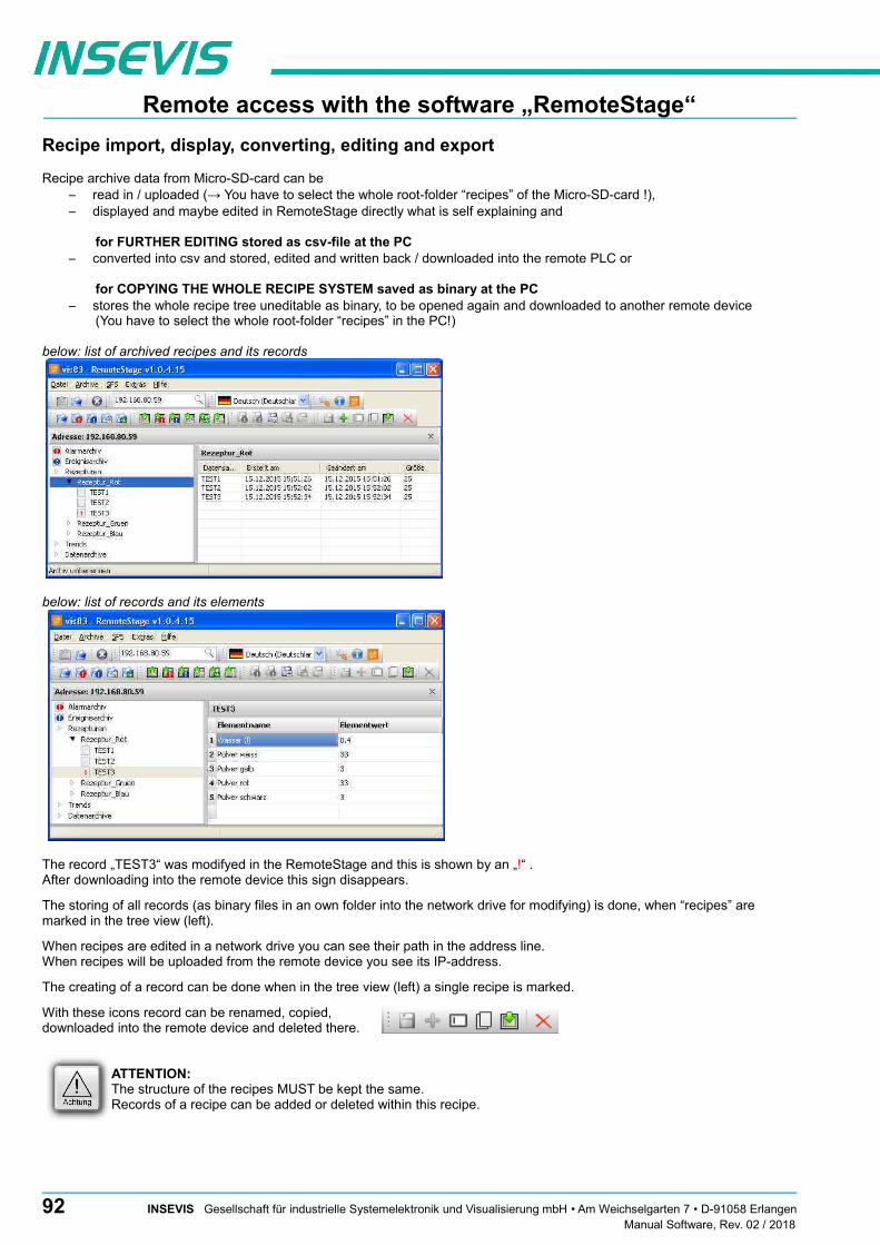
Remote access with the software „RemoteStage“
Recipe import, display, converting, editing and export
Recipe archive data from Micro-SD-card can be – read in / uploaded (→ You have to select the whole root-folder “recipes” of the Micro-SD-card !),– displayed and maybe edited in RemoteStage directly what is self explaining and
for FURTHER EDITING stored as csv-file at the PC– converted into csv and stored, edited and written back / downloaded into the remote PLC or
for COPYING THE WHOLE RECIPE SYSTEM saved as binary at the PC– stores the whole recipe tree uneditable as binary, to be opened again and downloaded to another remote device
(You have to select the whole root-folder “recipes” in the PC!)
below: list of archived recipes and its records
below: list of records and its elements
The record „TEST3“ was modifyed in the RemoteStage and this is shown by an „!“ . After downloading into the remote device this sign disappears.
The storing of all records (as binary files in an own folder into the network drive for modifying) is done, when “recipes” are marked in the tree view (left).
When recipes are edited in a network drive you can see their path in the address line. When recipes will be uploaded from the remote device you see its IP-address.
The creating of a record can be done when in the tree view (left) a single recipe is marked.
With these icons record can be renamed, copied,downloaded into the remote device and deleted there.
ATTENTION: The structure of the recipes MUST be kept the same. Records of a recipe can be added or deleted within this recipe.
92 INSEVIS Gesellschaft für industrielle Systemelektronik und Visualisierung mbH • Am Weichselgarten 7 • D-91058 ErlangenManual Software, Rev. 02 / 2018

Remote access with the software „RemoteStage“
Data (DB) archive upload, display, storing and download
Any data can be archived with the SFC 207 ARCHIVE onto the Micro-SD-card (binary or csv-data)and read back with the SFC 209 READFILE (see system functions).
Data archive display and storingThese data (DB) archived over S7-program to Micro-SD-card, can be read in and displayed and stored to the PC in the assigned format.
The format of the csv-file will be assigned by the S7-program (SFC207) and is not configurable by the RemoteStage. This can be done later on with any table calculation program by customer (because only he knows the format).
below: display of the data archives available on the Micro-SD-card
below: display of the data archives in txt-format available on the Micro-SD-card
below: display of the data archives as binaries available on the Micro-SD-card
With these icons data archives will be renamed, copied and - from RemoteStage V 1.0.4.18- downloaded into remote device or deleted.
INSEVIS Gesellschaft für industrielle Systemelektronik und Visualisierung mbH • Am Weichselgarten 7 • D-91058 Erlangen 93Manual Software, Rev. 02 / 2018

Remote access with the software „RemoteStage“
Command line of RemoteStage (Viewing mode)RemoteStage can be inserted in „planned tasks“ of the remote PC. A combination of multiple parameters is possible.
Here are available these special functions.
Automatic connecting to remote panel after starting PCWith his function a binary of the visualization is called and linked with the predefined IP-address of the remote panel (if this is available online only)
remotestage.exe /start /r=<remote> /v=<project binary>
Hint: If the binary name contains space-signs it is necessary to write it in “ like „C:\Test 1 2 3.vsbin“)
Automatic full screen after starting PCWith his function a binary of the visualization is called and the RemoteStage changes into full screen at the remote PC after automatic starting (Screen stays dark, because no IP-address was assigned here...)
remotestage.exe /start /full /r=<remote> /v=<project binary>
Hint: Use STRG+F5 to switch between full-/ part screen
Set up TCP port number for S7-communicationIf there are multiple PLCs to connect by a web enabled router/ gateway with port forwarding service
In this case the RemoteStage starts a communication with a remote device with the IP address 192.168.80.50 via the TCP port with the number 4500.
remotestage.exe /v=d:\visu\process.vsbin /r=192.168.80.50 /p=4500
Hint: The default port number for TCP is port 102 at the PLCs.
94 INSEVIS Gesellschaft für industrielle Systemelektronik und Visualisierung mbH • Am Weichselgarten 7 • D-91058 ErlangenManual Software, Rev. 02 / 2018

Remote access with the software „RemoteStage“
Command line of RemoteStage (Archive mode)RemoteStage can be used in batch process from command line with command line parameters, to save archives somewhere with a self defined name.
In the PC-OS Windows® batch files can be done time controlled in the task manager Start menue →All Programs →Accessories →System programs →Planned tasks → add a taskIn the wizard dialog can be assigned date and time for that job.
Read in (upload) message- and trend archives from remote deviceThe binaries of the messages and trends (assigned in the VisuStage before and created at runtime) will be read in, converted and stored in a path on the PC.
Command line
remotestage.exe /mode=<mode> /r=<remote> /o=<output file> /v=<project binary> /t=<trend number>
Parameters
mode: Archive file read inalarm_archive - read in alarm archive from remote device (alarm.bin)event_archive - read in event archive from remote device (event.bin)trend_archive - read in trend archive from remote device (trend_<trend number>.bin) (trend ID is assigned automatically by VisuStage at ressources / grayed out you can not change it)
remote: Remote device IP address
output file: File name of archive file to be stored in PC.This is optional parameter. If this parameter is not assigned, default archive name is used (e.g alarm.bin) and stored in same folder where remotestage.exe located.If file name includes space character, it should be quoted with " (quotation mark).Archive converted to CSV format if file name has .csv or .txt extention, otherwise it writes as binary format.
project binary: Visualization project binary file name
trend number: Trend ID-number which is automatically assigned in VisuStage. It is only used at "trend_archive" mode.
Samples
For example to read in alarm archive from INSEVIS PLC with IP address 192.168.80.50 and write to „d:\archive\alarm.csv“ file with CSV format you need this command
C:\>remotestage.exe /mode=alarm_archvie /r=192.168.80.50 /o=d:\archive\alarm.csv /v=d:\visu\myvisu.vsbin
For example to read in the sample-trend with ID6163 (from sample visualization of PC1560T) from Panel-PLC with IP-address 192.168.80.50 and to save it as csv-file to D:\archive\trend6163.csv you need this command
C:\>remotestage.exe /mode=trend_archive /r=192.168.80.50 /o=D:\archive\trend6163.csv /t=6163 /v=D:\PC156xT_2017_03.vsbin
INSEVIS Gesellschaft für industrielle Systemelektronik und Visualisierung mbH • Am Weichselgarten 7 • D-91058 Erlangen 95Manual Software, Rev. 02 / 2018

Remote access with the software „RemoteStage“
Read in (upload) recipe archive from remote deviceThe binaries of the (in VisuStage predefined) recipes and the of the records (created in runtime by the operator or by SFC206 from the S7-program) will be read in, converted and stored in a path on the PC.
Command line
remotestage.exe /mode=recipe /r=<remote> /v=<project binary> /recipe=<recipe name>/record=<record name> /o=<output file> /format=csv
Parameters
mode Recipe = read in the recipe data from remote-device
remote Remote device IP address
project binary Visualization binary name
recipe name Recipe name assigned in visualization project (NOT: View name)
record name Name of the record for saving of SPECIAL (single) records.If this parameter is not assigned, RemoteStage reads in ALL records, what belong to the recipe <recipe name> and stores it in a folder assigned by the parameter "/o=" before. → To configure the format of the output file as csv, the parameter "/format=csv" must be set, otherwise all datawill be stored a a binary.In the csv-files this format is predefined: ; (Semicolon) as field limiter and “ (quotation mark) as text separator. If this parameter is assigned, the format of the output file MUST BE predefined by the extension of the record name.→ If the file has an extension .csv or .txt, than it is a csv-format, otherwise the output file format is binary.
output file: Path and file name of the recipe record for the storing in the PC (optional parameter)If the parameter "/o=" is not assigned, a folder "Recipes\<recipe name>“ will be created in the project folder (where the visualization binary is kept) automatically and the recipe record stored as <record name>.rec.If file name includes space character, it should be quoted with " (quotation mark).
Samples
To read in e.g. a single recipe record „Orange“ from the recipe „Rezeptur_Rot“ from the INSEVIS Panel-PLC with the IP-address192.168.80.50 and to store it as csv-file to „D:\archive\“ this command line is required:
C:\>remotestage.exe /mode=recipe /r=192.168.80.50 /v=d:\visu\myvisu.vsbin /recipe=Rezeptur_Rot /record=Orange /o=D:\archive\Orange.csv
To read in e.g. ALL recipe records from the recipe „Rezeptur_Rot“ from the INSEVIS Panel-PLC with the IP-address 192.168.80.50 and to store it as csv-file to „D:\archive\“ this command line is required:
C:\>remotestage.exe /mode=recipe /r=192.168.80.50 /v=d:\visu\myvisu.vsbin /recipe=Rezeptur_Rot /o=D:\archive /format=csv
96 INSEVIS Gesellschaft für industrielle Systemelektronik und Visualisierung mbH • Am Weichselgarten 7 • D-91058 ErlangenManual Software, Rev. 02 / 2018

Remote access with the software „RemoteStage“
Write back (download) recipe archive into remote deviceWith this function the uploaded (and maybe modified) recipe data will be written back (downloaded) into the remote device. (from rev. 1.0.4.17 and PLC firmware 2.3.9 (all CPUs) or HMI firmware 1.2.7 CPU-V/-P and 1.2.6 CPU-T)
Attention: The structure of the receipes in the remote device may not be modified between upload and download. (No adding, deleting elements or changing the row of order)
Command lineremotestage.exe /mode=recipe_download /v=<project binary>
/recipe=<recipe name> /record=<record file(s)>
Parameters
project binary Binary fle of visualization project
recipe name In VisuStage projected recipe name (ATTENTION: not view name!)
record file(s) Recipe data to download into remote device
Samples
Following command line downloads ONE recipe record „Rot_123.rec“ of the recipe „Recipe_Rot“ from the folder D:\recipes into the remote device with the IP address 192.168.80.50
remotestage.exe /mode=recipe_download /v=d:\visu\process.vsbin /recipe=Recipe_Rot /record=d:\recipes\Rot_123.rec /r=192.168.80.50
Following command line downloads ALL recipe record of the recipe „Recipe_Rot“ from the folder D:\recipes into the remote device with the IP address 192.168.80.50
remotestage.exe /mode=recipe_download /v=d:\visu\process.vsbin /recipe=Recipe_Rot /record=d:\recipes\*.rec /r=192.168.80.50
INSEVIS Gesellschaft für industrielle Systemelektronik und Visualisierung mbH • Am Weichselgarten 7 • D-91058 Erlangen 97Manual Software, Rev. 02 / 2018

Remote access with the software „RemoteStage“
Read in (upload) data (DB-) archive from remote deviceThis function copies the data(DB-) archives created by S7-program with SFC207to the requested target path into the PC. A modification of the csv-format is not possible.
Command line
remotestage.exe /mode=data_archive /r=<remote> /archive=<archive file> /o=<output file>
Parameters
mode data_archive = read in the date (DB-) archive from remote-device
remote Remote device IP address
archive file: File name of the data (DB-) archiveIf there is no archive file assigned to this parameter, the RemoteStage stores all data (DB-) archives in a folder assigned by the parameter "/o=" before.
output file: Path and file name of the data (DB-) archive for the storing in the PC (optional parameter)If nothing is assigned for the parameter "/o=", a folder "UserData“ is created in the program folder (where the remotestage.exe is kept.If file name includes space character, it should be quoted with " (quotation mark).
To read in e.g. a data (DB-) archive „Test-DB“ from the INSEVIS Panel-PLC with the IP-address 192.168.80.50 and to store it ascsv-file to „D:\archive\Testdaten.csv“ this command line is required:
C:\>remotestage.exe /mode=data_archive /r=192.168.80.50 /archive=Test-DB /o=D:\archive\Testdaten.csv
Write back (download) data (DB-) archive into remote deviceWith this function the uploaded (and maybe modified) data (DB-) archives will be written back (downloaded) into the remote device. (from rev. 1.0.4.17 and PLC firmware 2.3.9 (all CPUs))
Attention: The programmer itself is responsible to keep the structure of the data (DB-) archives. If they will be modified, all referring reports must be adapted too!
Command lineremotestage.exe /mode=data_download /archive:=<archive file(s)>
Parameters
archive file(s) S7 User data archive file(s) to download to remote PLC
Samples
Following command line downloads ONE archive file "default_cfg.csv" from the folder D:\configs into the remote device with the IP address 192.168.80.50
remotestage.exe /mode=data_download /archive=d:\configs\default_cfg.csv /r=192.168.80.50
Following command line downloads ALL archive files from the folder D:\configs into the remote device with the IP address 192.168.80.50
remotestage.exe /mode=data_download /archive=d:\configs\*.* /r=192.168.80.50
98 INSEVIS Gesellschaft für industrielle Systemelektronik und Visualisierung mbH • Am Weichselgarten 7 • D-91058 ErlangenManual Software, Rev. 02 / 2018

Remote access with the software „RemoteStage“
Return codes
Return codes of remotestage.exe indicate the result of operation.Return code Meaning
0 Successfully read out and saved.
1 Invalid parameter or mandatory parameters are missing
2 Project binary file is invalid or not found
3 Remote IP address is invalid
4 Could not connect to remote device
5 SD card not inserted on remote device
6 Archive file not found on remote device
7 Remote device does not support archive file read service
8 Invalid archive data
9 Not enough system resource
11 Not enough system resource on remote device
14 Could not write to in give <output file>
15 Connection is broken
Sample of RemoteStage usage in batch process:
@remotestage /mode=alarm_archive /r=192.168.80.50 /o=d:\archive\alarm.csv /v=d:\visu\myvisu.vsbin@echo.@goto res%ERRORLEVEL%
:res4@echo Could not connect to remote device@goto :EOF
:res0@echo Successful read out and saved@goto :EOF
INSEVIS Gesellschaft für industrielle Systemelektronik und Visualisierung mbH • Am Weichselgarten 7 • D-91058 Erlangen 99Manual Software, Rev. 02 / 2018

Working with the software „ServiceStage“
With the free-of-cost software „ServiceStage“ it is possible to recognize INSEVIS-CPUs online and to change their state or program data. With this program a member of the service-team can do all the main functions for diagnostics and update by his PC/Laptop without other expensive tools.
Therefore you choose the network adapter of your PC (This one, what makes the network access to the CPUs). Select one of the CPUs displayed in the left window and press „Update“.The „LCD-blink test“ helps to identify the selected CPU. (yellow battery-LED blinks for 3 seconds). Also you can assign a new IP-address, Net mask and Router-IP-address of the selected CPU here.
Function overview
General informationDisplays the system data to inform only (likeserial number, firmware version, MAC-address).Shows editable data like
• IP-address, • Net mask and • Router-IP-address
as well as a blink test button to identify your CPU again.
Only for CPU-T: Firmwareupdate possible by Ethernet
Operating modeHere you can change the operating mode of youCPU between RUN and STOP (not for Panel-HMI). This change must be confirmed in an extrawindow.
Date and timeFor manual adustment of system date and time.By checking the box „Take from PC“ these datawill be taken over from your PC after pressing „Apply“.
100 INSEVIS Gesellschaft für industrielle Systemelektronik und Visualisierung mbH • Am Weichselgarten 7 • D-91058 ErlangenManual Software, Rev. 02 / 2018
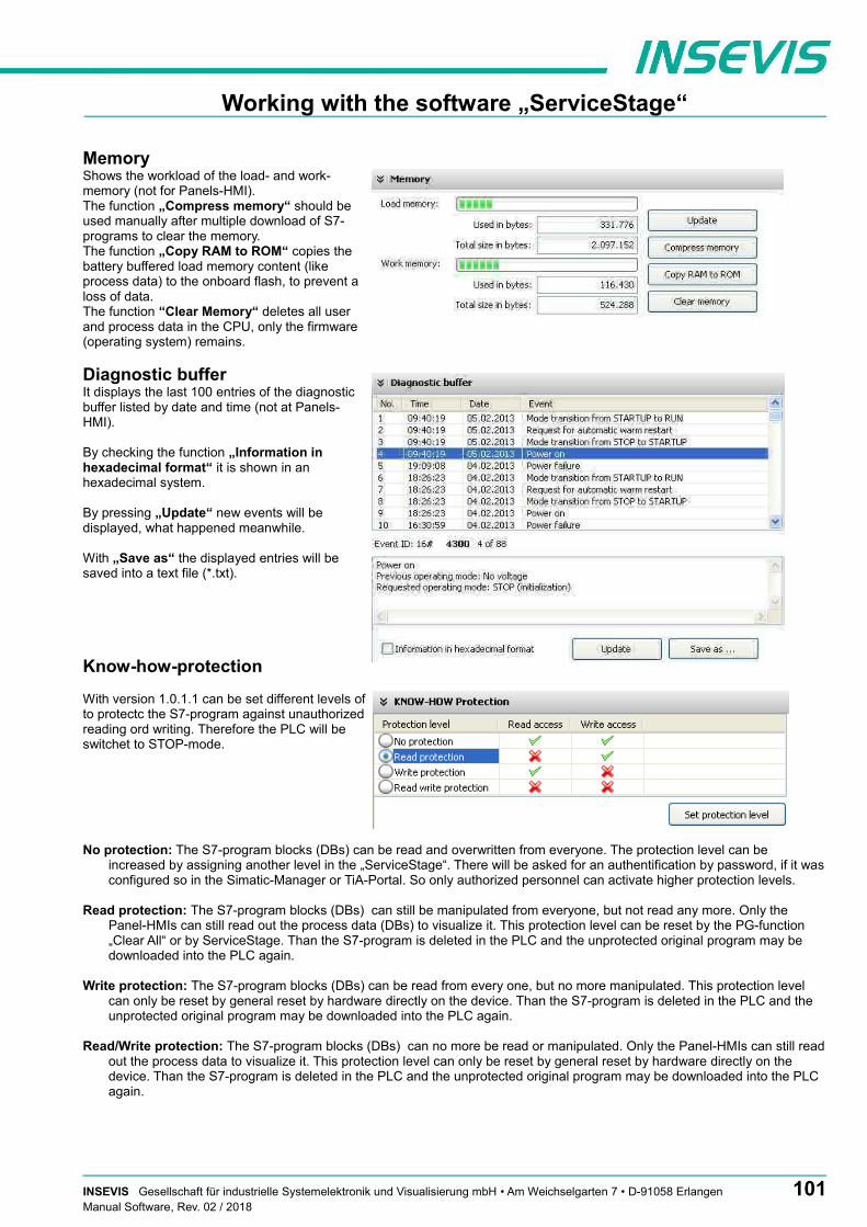
Working with the software „ServiceStage“
MemoryShows the workload of the load- and work-memory (not for Panels-HMI). The function „Compress memory“ should beused manually after multiple download of S7-programs to clear the memory.The function „Copy RAM to ROM“ copies thebattery buffered load memory content (likeprocess data) to the onboard flash, to prevent aloss of data.The function “Clear Memory“ deletes all userand process data in the CPU, only the firmware(operating system) remains.
Diagnostic bufferIt displays the last 100 entries of the diagnosticbuffer listed by date and time (not at Panels-HMI).
By checking the function „Information inhexadecimal format“ it is shown in anhexadecimal system.
By pressing „Update“ new events will bedisplayed, what happened meanwhile.
With „Save as“ the displayed entries will besaved into a text file (*.txt).
Know-how-protection
With version 1.0.1.1 can be set different levels ofto protectc the S7-program against unauthorizedreading ord writing. Therefore the PLC will beswitchet to STOP-mode.
No protection: The S7-program blocks (DBs) can be read and overwritten from everyone. The protection level can be increased by assigning another level in the „ServiceStage“. There will be asked for an authentification by password, if it wasconfigured so in the Simatic-Manager or TiA-Portal. So only authorized personnel can activate higher protection levels.
Read protection: The S7-program blocks (DBs) can still be manipulated from everyone, but not read any more. Only the Panel-HMIs can still read out the process data (DBs) to visualize it. This protection level can be reset by the PG-function „Clear All“ or by ServiceStage. Than the S7-program is deleted in the PLC and the unprotected original program may be downloaded into the PLC again.
Write protection: The S7-program blocks (DBs) can be read from every one, but no more manipulated. This protection level can only be reset by general reset by hardware directly on the device. Than the S7-program is deleted in the PLC and the unprotected original program may be downloaded into the PLC again.
Read/Write protection: The S7-program blocks (DBs) can no more be read or manipulated. Only the Panel-HMIs can still readout the process data to visualize it. This protection level can only be reset by general reset by hardware directly on the device. Than the S7-program is deleted in the PLC and the unprotected original program may be downloaded into the PLC again.
INSEVIS Gesellschaft für industrielle Systemelektronik und Visualisierung mbH • Am Weichselgarten 7 • D-91058 Erlangen 101Manual Software, Rev. 02 / 2018

Working with the software „ServiceStage“
Block UpdateThis function makes it possible to download- the S7-user program as MemoryCard-file *.wld- the INSEVIS-binary for visualization file as *.vsbin and- the INSEVIS-configuration file as *.csbin via the network into the CPU
By this software „ServiceStage“ it is possible to give away your data in a wld (S7) or binary (INSEVIS) format to those, who care for diagnostics, maintenance or update. You can keep your source data in your company and must not fear to be copied.
* The WLD-file is a binary file with S7-system data (SDBs) and S7-program blocks (OBs, FBs, FCs, DBs).
After creating a WLD file in SimaticManager/TIA-Portal (at the menue: „File → Memory Card File → New“) you can copy DIFFERENT DBs with or without their system dats into the window of the new S7-Memory-Card-File by drag´n drop. So it is possible to download WHOLE S7-projects OR SINGLE DBs with/without their system data.
ATTENTION: When inserting system data, • they shall be uploaded from a PLC with included ConfigStage-configuration
(Menue: „PLC → Upload Station to PG“), because the are “ConfigStage-configured” already or • the system data of the SimaticManager overwrite the ConfigStage-system system configuration.
In that case the *.csbin-file of the project must be downloaded again after the WLD-file was downloaded.
ATTENTION: When using Block Upload for restore• With firmware 2.3.6 a Restore can only bedone by WLD- and VSBIN-file. CSBIN-file will be ignored. So the
WLD-file MUST CONTAIN these system data, who where downloaded with CSBIN before.• If the WLD-file does not contain system data, program stops after restore because of missing data.
If the Hardware configuration block of the target device contains another IP-address than it is assigned to the configuration blocks of the blocks you do download into the device (WLD / VSBIN / CSBIN), it can happen, that you loose the connection aftertransfer. To avoid this, the ServiceStage from Rev. 1.0.1.9 asks, if the target-IP-configuration shall be replaced or not.
102 INSEVIS Gesellschaft für industrielle Systemelektronik und Visualisierung mbH • Am Weichselgarten 7 • D-91058 ErlangenManual Software, Rev. 02 / 2018

Working with the software „ServiceStage“
Online BackupThis function creates an WLD-file with allthe S7-system data and all OB, DB, FB,SFB and SFC and copies this file with thevisualization binary file into a folder„backups“.
With these data S7-programs andvisualizations can be updatet by a Micro-SD-card only – complete without any PC.(more at „System functions“, chapter „Databackup and restore“)
ATTENTION:• To make a visualization backup, it must be allowed to RemoteStage BEFORE, when doing the visualization
in VisuStage (check the upload-function in VisuStage-project-header), if necessary a PIN-input is required. Additional a password for communication must be typed in, when assigned in SimaticManager/ TIA/ ConfigStage.
• If “Read Protection” is assigned to the device an “Online Backup” is not possible any more.
INSEVIS Gesellschaft für industrielle Systemelektronik und Visualisierung mbH • Am Weichselgarten 7 • D-91058 Erlangen 103Manual Software, Rev. 02 / 2018

104 INSEVIS Gesellschaft für industrielle Systemelektronik und Visualisierung mbH • Am Weichselgarten 7 • D-91058 ErlangenManual Software, Rev. 02 / 2018