indexable drills - · pdf filechucking reamers – hss, ... met-cut is committed to...
TRANSCRIPT

METCUT®
Indexable Drills 7
Positive Rake Drills with Trochoid Inserts . 8
2.5 x Diameter, Series 273. ...................................................... 82.5 x Diameter, Series 273 Metric. .......................................... 94.5 x Diameter, Series 273. ................................................... 104.5 x Diameter, Series 273 Metric. ....................................... 113.5 x Diameter, Series 273. ................................................... 123.5 x Diameter, Series 273 Metric. ....................................... 125.5 x Diameter, Series 273. ................................................... 135.5 x Diameter, Series 273 Metric. ....................................... 13
Negative Rake Drills . ........................................................... 14
1.5 x Diameter, Series 272. ................................................... 142.5 x Diameter, Series 470......................................... 14-152.5 x Diameter, Series 270. ............................................. 14-15
Double-Feed Drills, Series 277. ........................................ 16
Spade Blade Holders 17-19
Straight Shank, Straight Flute ......................................... 17Straight Shank, Helical Flute ...................................... 17-18Taper Shank, Straight Flute ....................................... 18-19Taper Shank, Helical Flute .............................................. 19
Accessories for Indexable Drills . ................................. 20
Coolant Glands, Series 290. .................................................. 20Inserts, Positive Rake, Trochoid. .......................................... 20
Application Information . ............................................. 21-22
Reamers 23
Custom Sharpened Reamers . ........................................ 26Coolant Feed Reamers – HSS, Series OF. ....................... 26Coolant Feed Reamers – Carbide, Series SOFC, OFC. . 27Chucking Reamers – HSS, Series CR. ............................... 28Chucking Reamers – Carbide, Series SCRC, CRC. ........ 29
Chucking Coolant Feed Reamers . ............................... 30
Chucking Coolant Feed Reamers – HSS, Series COF. .. 30Chucking Coolant Feed Reamers – Carbide,
Series COFC. ....................................................................... 30
Floating Holders . .................................................................. 31
Tool Stationary, Fixed Center, Series FL. .......................... 31Tool Stationary, Adjustable, Series AOFF. ......................... 31Tool Rotating, Series AA, AB, AC, AD. ......................... 32-33
Application Information,Specials & Reamers Questionnaire . ................... 34-38
METCUT®
See Inside Back Cover forProduct Index by Series Number
METCUT®. . . Hole Making andHole Finishing Tool Specialists
METCUT® has been a manufacturer of highquality cutting tools for more than 50 years, andduring that time has earned a reputation forinnovative designs in standard as well as specialtooling. We take pride in our application engi-neering expertise and our ability to design spe-cial cutters to help our customers meet theirproduction requirements. A few examples of ourspecial tool capabilities are illustrated on thepages 2 through 6.
Integrated Design and ProductionAt METCUT, we make extensive use of the mostadvanced CAD/CAM technology for tool designand part programming.
Certified Quality and On-Time DeliveryOur quality program has been approved andcertified by several major manufacturers. MET-CUT is committed to customer service and satis-faction.
Call us toll free with your next inquiry:888-434-4186
or fax us your orders:815-226-0063
Quotations:Phone: 888-434-4370, ext. 5Fax: 888-434-4264
]]
EXPANDED LINE OFFERING]]
]NEW PRODUCTS
]
]]
]]
METCUT®
Back Spotfacers & Back Counterbores 69
Balanced Drive Back Spotfacers – HSS & TCT,Series 150 & 250. ................................................................ 70
Balanced Drive Back Counterbores – HSS,Series 151. ............................................................................ 71
Pilots for Balanced Drive, Straight Shank, Series 453. ... 72Pilots for Balanced Drive, Taper Shank, Series 450. ....... 72
Ball Pin Drive Back Spotfacers, Type D – HSS,Series 351x. .......................................................................... 73
Pilots with Straight Shank for Ball Pin Drive,Series 357x. .......................................................................... 74
Port Contour Cutters 75
SAE J1926, MS 16142 . ........................................................ 76HSS – Straight Shank, Series 163. ...................................... 76HSS – Taper Shank, Series 162. ......................................... 76HSS – Taper Shank w/ Extra Length Reamer,
Series 161. ............................................................................ 77HSS – Radial Drive, Series 160 . .......................................... 77TCT – Straight Shank, Series 263. ...................................... 78TCT – Taper Shank, Series 262. .......................................... 78TCT – Taper Shank w/ Extra Length Reamer,
Series 261. ............................................................................ 79TCT – Radial Drive, Series 260. ........................................... 79Indexable – Straight Shank, Series 267. ............................ 80Indexable – Double Feed Porting Tool, Series 367 ........ 81Double Feed Porting Tool w/Spade Blade, Series 467... 81
ISO 6149-1, Metric . ............................................................... 82
HSS – Straight Shank, Series 169. ...................................... 82TCT – Straight Shank, Series 269. ...................................... 83
MS 33649, NASA MC 240 . ................................................. 84
HSS – Straight Shank, Series 164. ...................................... 84TCT – Straight Shank, Series 264. ...................................... 84Indexable – Straight Shank, Series 268. ............................ 85BSPP/BSPF (Rp) BSI BS21, TCT, Series 265 ............... 86
Port Details . ............................................................................. 86
Port Contour Application Information . ..................... 87
Pipe Tap Cutters, Series 186 and 187. ............................ 88
Core Drills, Spot & Chamfer Drills 89
Square Drive Core Drills – HSS, Series 130. ............. 90Holders for Core Drills, Series 330, 331 ......................... 90Screws for Square Drive Core Drills, Series 054. ............. 90
Spot & Chamfer Drills – HSS & Indexable,Series 184 and 284. ............................................................ 91
Technical Reference Information 92
Equivalents and Conversions . ...................................... 92
Drive Details . ..................................................................... 93-95
Metalcutting Safety . ............................................................. 96
Counterbores & Countersinks 39
Counterbores . ......................................................................... 40
Pin Drive Counterbores – HSS, Series 100. ...................... 40Pin Drive Counterbores – TCT, Series 200. ....................... 41Stub Taper Counterbores – HSS, Series 110. .................. 42Stub Taper Counterbores – TCT, Series 210. ................... 43Stub Taper Counterbores – Indexable, Series 7710. ....... 44Radial Drive Counterbores – HSS, Series 120. ................ 45Radial Drive Counterbores – TCT, Series 220. ................. 46HEX Drive, Type A Counterbores – HSS, Series 307x. .. 47HEX Drive,Type C Counterbores – HSS, Series 327x. ... 48HEX Drive, Type C Counterbores – TCT, Series 325x. .. 49HEX Drive, Type C Counterbores – Indexable, ...................
Series 7610. .......................................................................... 50Straight Shank Counterbores – Indexable, Series 7810. 51Counterbores for Cap Screws, Series 183. ........................ 52Counterbore Application Information. .................................. 53
Countersinks . .......................................................................... 54
Pin Drive Countersinks – HSS, Piloted, Series 101. ........ 54Indexable Countersinks w/Straight Shank, Series 266 ... 54Radial Drive Countersinks – HSS, Piloted, Series 121. ... 55Radial Drive Countersinks – HSS, Unpiloted, Series 122.56Straight Shank Countersinks – TCT, 3 Flute,
Series 179.................................................................... 58Straight Shank Countersinks – HSS, 4 Flute, Series 177 58Straight Shank Countersink – HSS, Single Flute,
Series 166.................................................................... 58
Holders for Counterbores & Countersinks . ............ 59
Pin Drive Holders w/ Taper Shank, Series 300. ................ 59Pin Drive Holders w/ Straight Shank, Series 303. ............ 59Stub Taper Holders w/ Taper Shank, Series 310. ............ 60Radial Drive Holders w/ Straight Shank, Series 323. ....... 60Radial Drive Holders w/ Taper Shank, Series 320. .......... 61Radial Drive Holders w/ Threaded Shank, Series 321. ... 61HEX Drive Type A Holders w/ Straight Shank,
Series 3305. .......................................................................... 62HEX Drive Type A Holders w/ Taper Shank,
Series 3300, 3320. .............................................................. 62HEX Drive Type C Holders w/ Straight Shank,
Series 3365. .......................................................................... 63HEX Drive Type C Holders w/ Taper Shank,
Series 3360, 3380. .............................................................. 63
Pilots for Counterbores & Countersinks . ................ 64
Long Pilots for Pin Drive & Radial Drive Tools,Series 400. ...................................................................... 64-65
Short Pilots for Stub Taper & Indexable Tools,Series 410. ............................................................................ 66
Pilots for HEX Drive Type A Counterbores,Series 500x. .......................................................................... 67
Pilots for HEX Drive Type C Counterbores,Series 502x. .......................................................................... 68
]]
EXPANDED LINE OFFERING]]
]NEW PRODUCTS
]]
]
1
]]
]
]
]
]
]
METCUT®
METCUT®
METCUT®
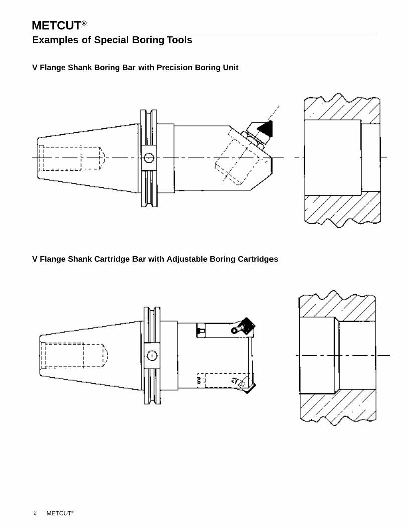
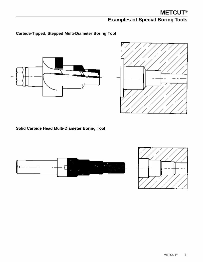
Examples of Special Boring Tools
V Flange Shank Boring Bar with Precision Boring Unit
V Flange Shank Cartridge Bar with Adjustable Boring Cartridges
2
METCUT®
Carbide-Tipped, Stepped Multi-Diameter Boring Tool
Solid Carbide Head Multi-Diameter Boring Tool
METCUT®
Examples of Special Boring Tools
3
METCUT®
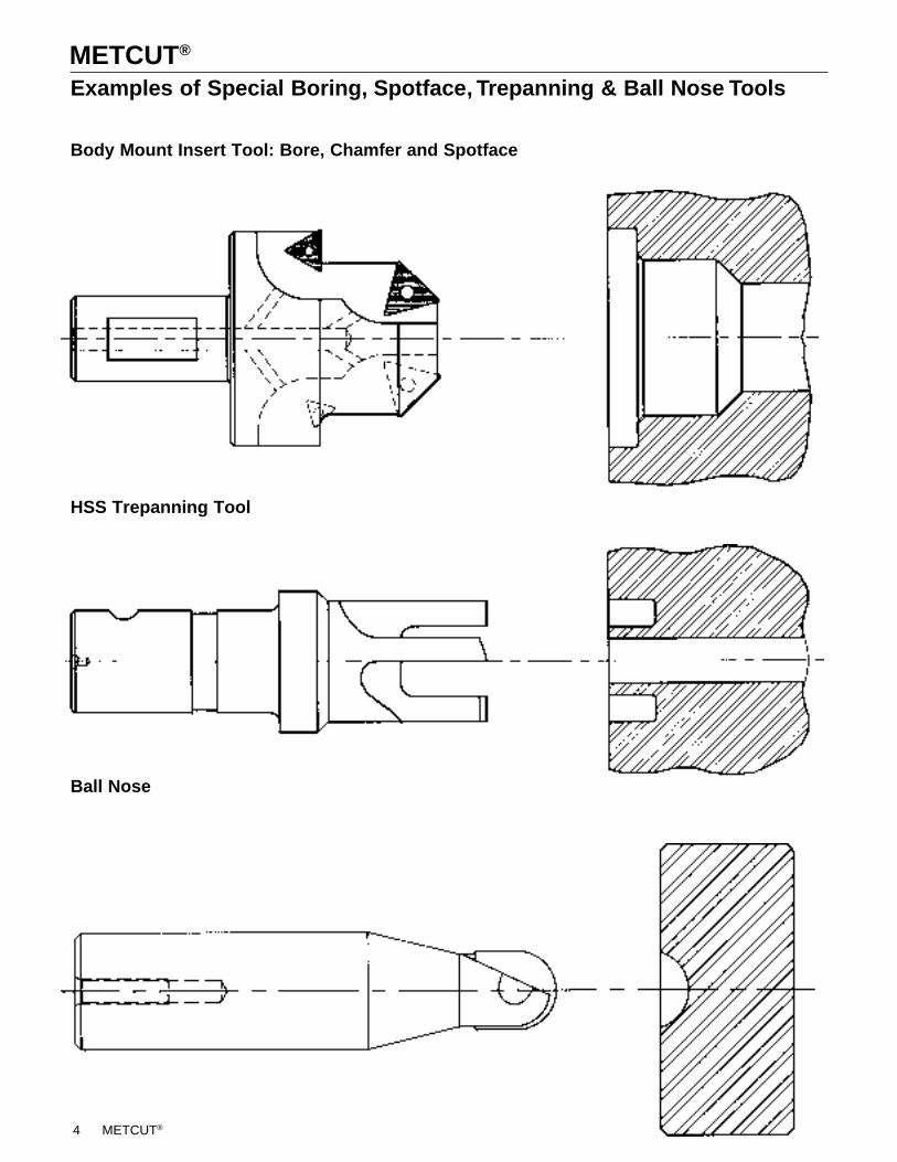
Examples of Special Boring, Spotface, Trepanning & Ball Nose Tools
Body Mount Insert Tool: Bore, Chamfer and Spotface
METCUT®
HSS Trepanning Tool
Ball Nose
4
METCUT®
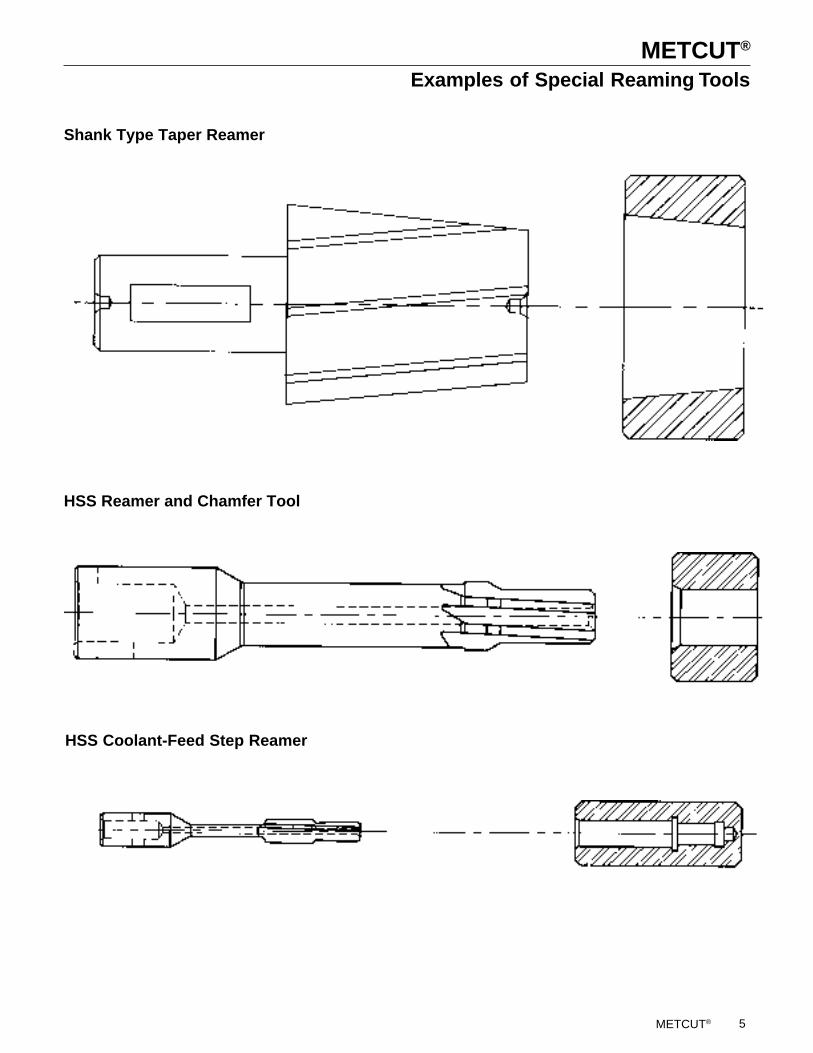
Shank Type Taper Reamer
HSS Reamer and Chamfer Tool
HSS Coolant-Feed Step Reamer
METCUT®
Examples of Special Reaming Tools
5
METCUT®
METCUT®
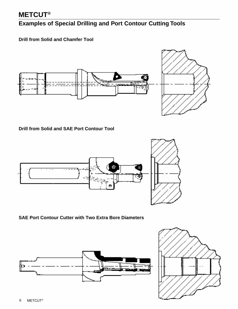
Examples of Special Drilling and Port Contour Cutting Tools
Drill from Solid and Chamfer Tool
Drill from Solid and SAE Port Contour Tool
SAE Port Contour Cutter with Two Extra Bore Diameters
6
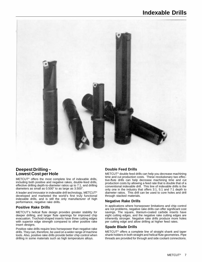
METCUT® 7
Deepest Drilling –Lowest Cost per HoleMETCUT® offers the most complete line of indexable drills,including both positive and negative rakes, double-feed drills,effective drilling depth-to-diameter ratios up to 7:1, and drillingdiameters as small as 0.500" to as large as 3.500".A leader and innovator in indexable drill technology, METCUT®
developed and marketed the world’s first truly functionalindexable drills, and is still the only manufacturer of highperformance, negative rake drills.
Positive Rake DrillsMETCUT’s helical flute design provides greater stability fordeeper drilling, and larger flute openings for improved chipevacuation. Trochoid-shaped inserts have three cutting edgeswith superior edge strength compared to other positive rakeinsert designs.Positive rake drills require less horsepower than negative rakedrills. They can, therefore, be used on a wider range of machinetools. Also, positive rake drills provide better chip control whendrilling in some materials such as high temperature alloys.
Indexable Drills
Double Feed DrillsMETCUT® double feed drills can help you decrease machiningtime and cut production costs. These revolutionary two effec-tive-flute drills can help decrease machining time and cutproduction costs by allowing a feed rate that is double that of aconventional indexable drill. This line of indexable drills is theonly one in the industry that offers 3:1, 5:1 and 7:1 depth todiameter ratios. This drill can be used to core holes and drillthrough stacked materials.
Negative Rake DrillsIn applications where horsepower limitations and chip controlare not problems, negative rake drills can offer significant costsavings. The square, titanium-coated carbide inserts haveeight cutting edges, and the negative rake cutting edges areinherently stronger. Negative rake drills produce more holesper cutting edge and allow drilling at higher feed rates.
Spade Blade DrillsMETCUT® offers a complete line of straight shank and tapershank holders in both straight and helical flute geometries. Pipethreads are provided for through and side coolant connections.
8 METCUT®
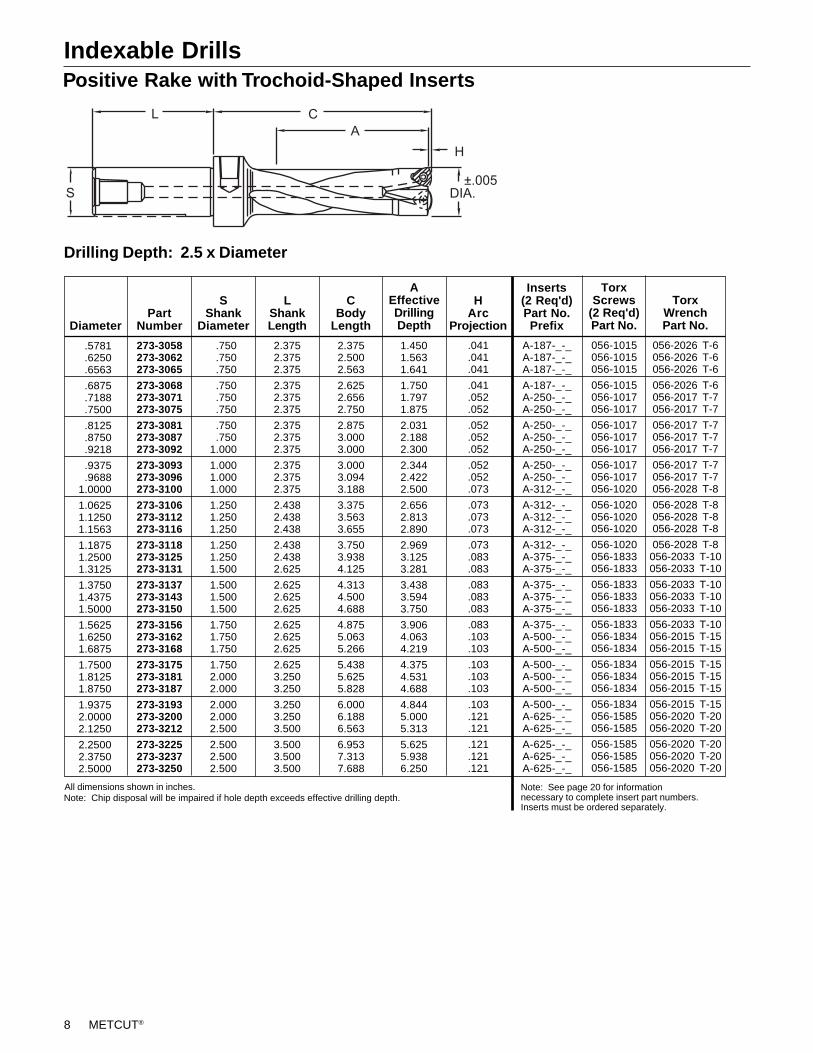
Indexable DrillsPositive Rake with Trochoid-Shaped Inserts
Drilling Depth: 2.5 x Diameter
273-3058273-3062273-3065
273-3068273-3071273-3075
273-3081273-3087273-3092
273-3093273-3096273-3100
273-3106273-3112273-3116
273-3118273-3125273-3131
273-3137273-3143273-3150
273-3156273-3162273-3168
273-3175273-3181273-3187
273-3193273-3200273-3212
273-3225273-3237273-3250
PartNumberDiameter
LShankLength
.041
.041
.041
.041
.052
.052
.052
.052
.052
.052
.052
.073
.073
.073
.073
.073
.083
.083
.083
.083
.083
.083
.103
.103
.103
.103
.103
.103
.121
.121
.121
.121
.121
HArc
Projection
A-187-_-_A-187-_-_A-187-_-_
A-187-_-_A-250-_-_A-250-_-_
A-250-_-_A-250-_-_A-250-_-_
A-250-_-_A-250-_-_A-312-_-_
A-312-_-_A-312-_-_A-312-_-_
A-312-_-_A-375-_-_A-375-_-_
A-375-_-_A-375-_-_A-375-_-_
A-375-_-_A-500-_-_A-500-_-_
A-500-_-_A-500-_-_A-500-_-_
A-500-_-_A-625-_-_A-625-_-_
A-625-_-_A-625-_-_A-625-_-_
SShank
Diameter
CBody
Length
Inserts(2 Req'd)Part No.Prefix
AEffectiveDrillingDepth
056-2026 T-6056-2026 T-6056-2026 T-6
056-2026 T-6056-2017 T-7056-2017 T-7
056-2017 T-7056-2017 T-7056-2017 T-7
056-2017 T-7056-2017 T-7056-2028 T-8
056-2028 T-8056-2028 T-8056-2028 T-8
056-2028 T-8056-2033 T-10056-2033 T-10
056-2033 T-10056-2033 T-10056-2033 T-10
056-2033 T-10056-2015 T-15056-2015 T-15
056-2015 T-15056-2015 T-15056-2015 T-15
056-2015 T-15056-2020 T-20056-2020 T-20
056-2020 T-20056-2020 T-20056-2020 T-20
TorxScrews
(2 Req'd)Part No.
056-1015056-1015056-1015
056-1015056-1017056-1017
056-1017056-1017056-1017
056-1017056-1017056-1020
056-1020056-1020056-1020
056-1020056-1833056-1833
056-1833056-1833056-1833
056-1833056-1834056-1834
056-1834056-1834056-1834
056-1834056-1585056-1585
056-1585056-1585056-1585
TorxWrenchPart No.
.5781
.6250
.6563
.6875
.7188
.7500
.8125
.8750
.9218
.9375
.96881.0000
1.06251.12501.1563
1.18751.25001.3125
1.37501.43751.5000
1.56251.62501.6875
1.75001.81251.8750
1.93752.00002.1250
2.25002.37502.5000
2.3752.5002.563
2.6252.6562.750
2.8753.0003.000
3.0003.0943.188
3.3753.5633.655
3.7503.9384.125
4.3134.5004.688
4.8755.0635.266
5.4385.6255.828
6.0006.1886.563
6.9537.3137.688
1.4501.5631.641
1.7501.7971.875
2.0312.1882.300
2.3442.4222.500
2.6562.8132.890
2.9693.1253.281
3.4383.5943.750
3.9064.0634.219
4.3754.5314.688
4.8445.0005.313
5.6255.9386.250
.750
.750
.750
.750
.750
.750
.750
.7501.000
1.0001.0001.000
1.2501.2501.250
1.2501.2501.500
1.5001.5001.500
1.7501.7501.750
1.7502.0002.000
2.0002.0002.500
2.5002.5002.500
2.3752.3752.375
2.3752.3752.375
2.3752.3752.375
2.3752.3752.375
2.4382.4382.438
2.4382.4382.625
2.6252.6252.625
2.6252.6252.625
2.6253.2503.250
3.2503.2503.500
3.5003.5003.500
Note: See page 20 for informationnecessary to complete insert part numbers.Inserts must be ordered separately.
All dimensions shown in inches.Note: Chip disposal will be impaired if hole depth exceeds effective drilling depth.
METCUT® 9
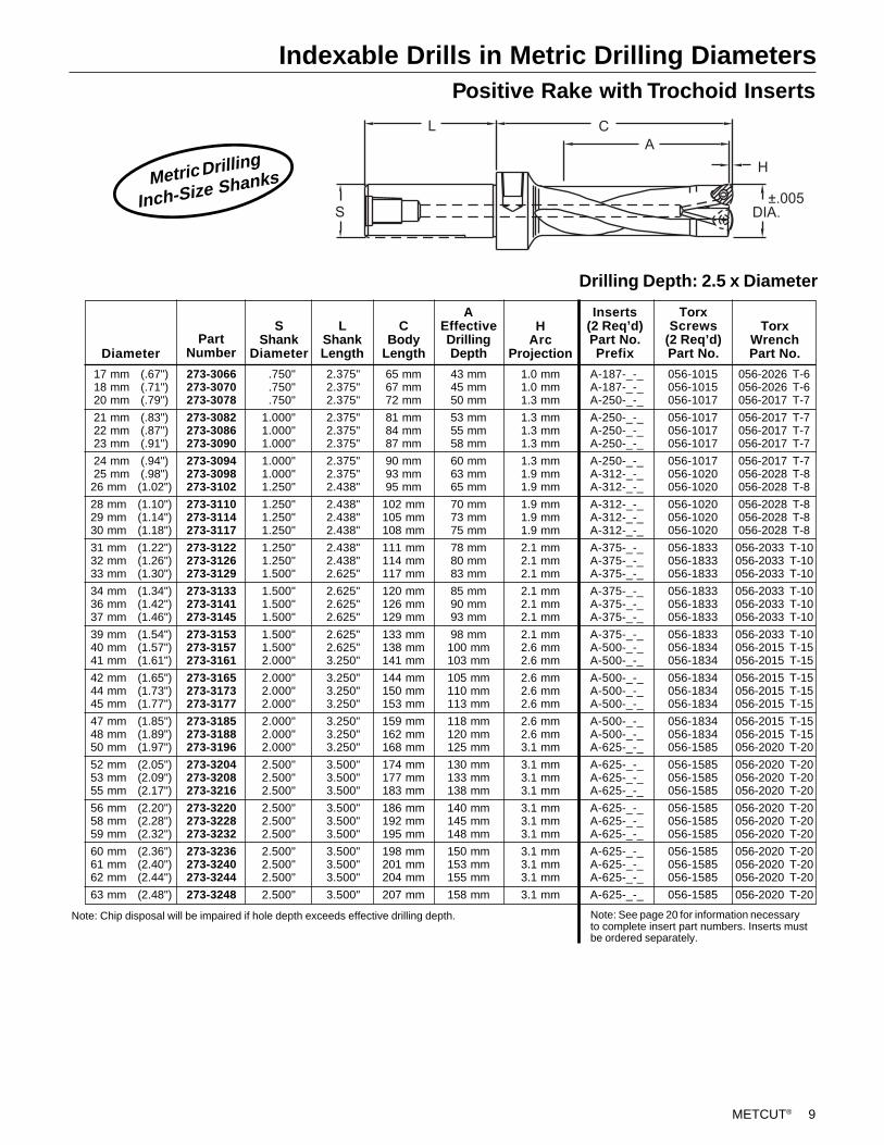
Indexable Drills in Metric Drilling Diameters
Drilling Depth: 2.5 x Diameter
Positive Rake with Trochoid Inserts
Metric Drilling
Inch-Size Shanks
Note: See page 20 for information necessaryto complete insert part numbers. Inserts mustbe ordered separately.
056-2026 T-6056-2026 T-6056-2017 T-7
056-2017 T-7056-2017 T-7056-2017 T-7
056-2017 T-7056-2028 T-8056-2028 T-8
056-2028 T-8056-2028 T-8056-2028 T-8
056-2033 T-10056-2033 T-10056-2033 T-10
056-2033 T-10056-2033 T-10056-2033 T-10
056-2033 T-10056-2015 T-15056-2015 T-15
056-2015 T-15056-2015 T-15056-2015 T-15
056-2015 T-15056-2015 T-15056-2020 T-20
056-2020 T-20056-2020 T-20056-2020 T-20
056-2020 T-20056-2020 T-20056-2020 T-20
056-2020 T-20056-2020 T-20056-2020 T-20
056-2020 T-20
2.375"2.375"2.375"
2.375"2.375"2.375"
2.375"2.375"2.438"
2.438"2.438"2.438"
2.438"2.438"2.625"
2.625"2.625"2.625"
2.625"2.625"3.250"
3.250"3.250"3.250"
3.250"3.250"3.250"
3.500"3.500"3.500"
3.500"3.500"3.500"
3.500"3.500"3.500"
3.500"
65 mm67 mm72 mm
81 mm84 mm87 mm
90 mm93 mm95 mm
102 mm105 mm108 mm
111 mm114 mm117 mm
120 mm126 mm129 mm
133 mm138 mm141 mm
144 mm150 mm153 mm
159 mm162 mm168 mm
174 mm177 mm183 mm
186 mm192 mm195 mm
198 mm201 mm204 mm
207 mm
43 mm45 mm50 mm
53 mm55 mm58 mm
60 mm63 mm65 mm
70 mm73 mm75 mm
78 mm80 mm83 mm
85 mm90 mm93 mm
98 mm100 mm103 mm
105 mm110 mm113 mm
118 mm120 mm125 mm
130 mm133 mm138 mm
140 mm145 mm148 mm
150 mm153 mm155 mm
158 mm
1.0 mm1.0 mm1.3 mm
1.3 mm1.3 mm1.3 mm
1.3 mm1.9 mm1.9 mm
1.9 mm1.9 mm1.9 mm
2.1 mm2.1 mm2.1 mm
2.1 mm2.1 mm2.1 mm
2.1 mm2.6 mm2.6 mm
2.6 mm2.6 mm2.6 mm
2.6 mm2.6 mm3.1 mm
3.1 mm3.1 mm3.1 mm
3.1 mm3.1 mm3.1 mm
3.1 mm3.1 mm3.1 mm
3.1 mm
A-187-_-_A-187-_-_A-250-_-_
A-250-_-_A-250-_-_A-250-_-_
A-250-_-_A-312-_-_A-312-_-_
A-312-_-_A-312-_-_A-312-_-_
A-375-_-_A-375-_-_A-375-_-_
A-375-_-_A-375-_-_A-375-_-_
A-375-_-_A-500-_-_A-500-_-_
A-500-_-_A-500-_-_A-500-_-_
A-500-_-_A-500-_-_A-625-_-_
A-625-_-_A-625-_-_A-625-_-_
A-625-_-_A-625-_-_A-625-_-_
A-625-_-_A-625-_-_A-625-_-_
A-625-_-_
056-1015056-1015056-1017
056-1017056-1017056-1017
056-1017056-1020056-1020
056-1020056-1020056-1020
056-1833056-1833056-1833
056-1833056-1833056-1833
056-1833056-1834056-1834
056-1834056-1834056-1834
056-1834056-1834056-1585
056-1585056-1585056-1585
056-1585056-1585056-1585
056-1585056-1585056-1585
056-1585
Diameter
CBody
Length
AEffectiveDrillingDepth
HArc
Projection
Inserts(2 Req’d)Part No.Prefix
TorxScrews
(2 Req’d)Part No.
TorxWrenchPart No.
17 mm (.67")18 mm (.71")20 mm (.79")
21 mm (.83")22 mm (.87")23 mm (.91")
24 mm (.94")25 mm (.98")26 mm (1.02")
28 mm (1.10")29 mm (1.14")30 mm (1.18")
31 mm (1.22")32 mm (1.26")33 mm (1.30")
34 mm (1.34")36 mm (1.42")37 mm (1.46")
39 mm (1.54")40 mm (1.57")41 mm (1.61")
42 mm (1.65")44 mm (1.73")45 mm (1.77")
47 mm (1.85")48 mm (1.89")50 mm (1.97")
52 mm (2.05")53 mm (2.09")55 mm (2.17")
56 mm (2.20")58 mm (2.28")59 mm (2.32")
60 mm (2.36")61 mm (2.40")62 mm (2.44")
63 mm (2.48")
Note: Chip disposal will be impaired if hole depth exceeds effective drilling depth.
LShankLength
SShank
DiameterPart
Number
.750"
.750"
.750"
1.000"1.000"1.000"
1.000"1.000"1.250"
1.250"1.250"1.250"
1.250"1.250"1.500"
1.500"1.500"1.500"
1.500"1.500"2.000"
2.000"2.000"2.000"
2.000"2.000"2.000"
2.500"2.500"2.500"
2.500"2.500"2.500"
2.500"2.500"2.500"
2.500"
273-3066273-3070273-3078
273-3082273-3086273-3090
273-3094273-3098273-3102
273-3110273-3114273-3117
273-3122273-3126273-3129
273-3133273-3141273-3145
273-3153273-3157273-3161
273-3165273-3173273-3177
273-3185273-3188273-3196
273-3204273-3208273-3216
273-3220273-3228273-3232
273-3236273-3240273-3244
273-3248
10 METCUT®
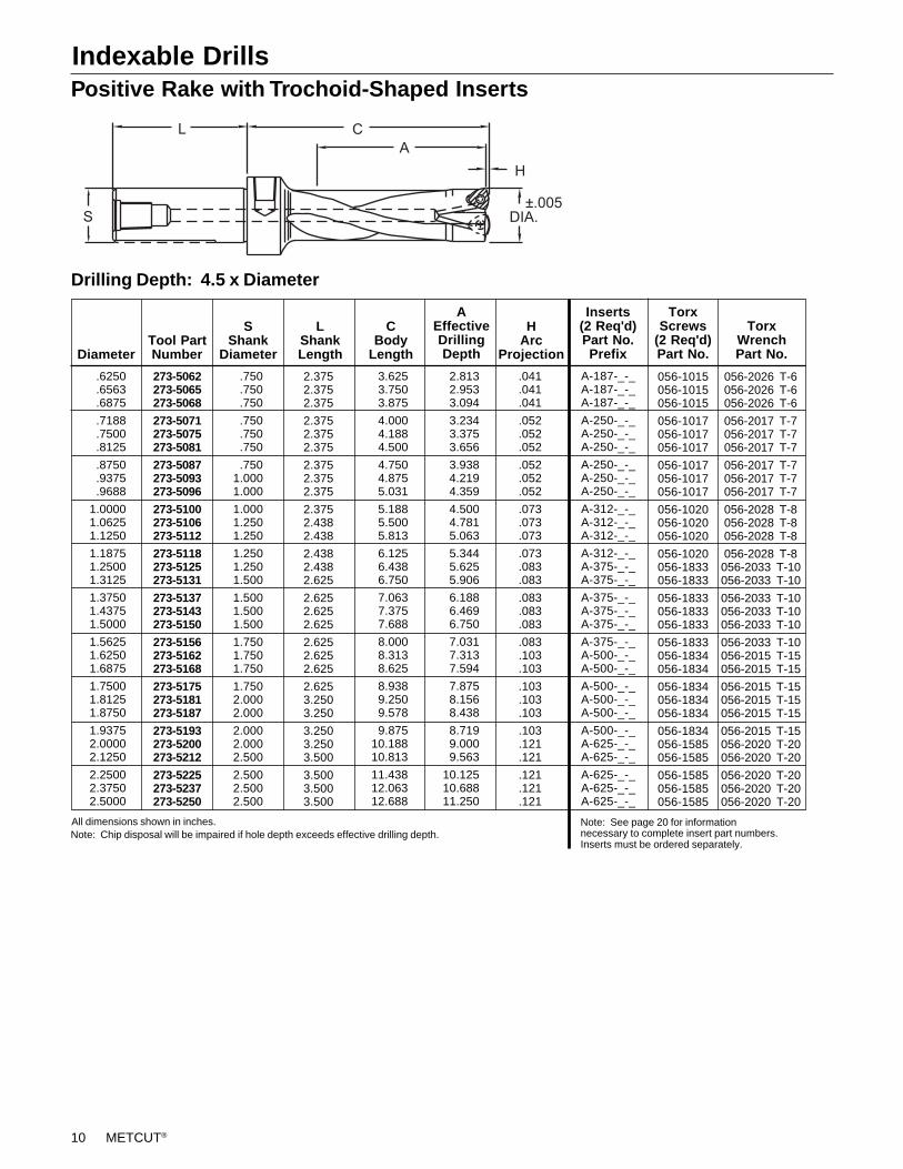
Positive Rake with Trochoid-Shaped InsertsIndexable Drills
Drilling Depth: 4.5 x Diameter
A-187-_-_A-187-_-_A-187-_-_
A-250-_-_A-250-_-_A-250-_-_
A-250-_-_A-250-_-_A-250-_-_
A-312-_-_A-312-_-_A-312-_-_
A-312-_-_A-375-_-_A-375-_-_
A-375-_-_A-375-_-_A-375-_-_
A-375-_-_A-500-_-_A-500-_-_
A-500-_-_A-500-_-_A-500-_-_
A-500-_-_A-625-_-_A-625-_-_
A-625-_-_A-625-_-_A-625-_-_
056-2026 T-6056-2026 T-6056-2026 T-6
056-2017 T-7056-2017 T-7056-2017 T-7
056-2017 T-7056-2017 T-7056-2017 T-7
056-2028 T-8056-2028 T-8056-2028 T-8
056-2028 T-8056-2033 T-10056-2033 T-10
056-2033 T-10056-2033 T-10056-2033 T-10
056-2033 T-10056-2015 T-15056-2015 T-15
056-2015 T-15056-2015 T-15056-2015 T-15
056-2015 T-15056-2020 T-20056-2020 T-20
056-2020 T-20056-2020 T-20056-2020 T-20
Inserts(2 Req'd)Part No.Prefix
TorxScrews
(2 Req'd)Part No.
056-1015056-1015056-1015
056-1017056-1017056-1017
056-1017056-1017056-1017
056-1020056-1020056-1020
056-1020056-1833056-1833
056-1833056-1833056-1833
056-1833056-1834056-1834
056-1834056-1834056-1834
056-1834056-1585056-1585
056-1585056-1585056-1585
TorxWrenchPart No.
273-5062273-5065273-5068
273-5071273-5075273-5081
273-5087273-5093273-5096
273-5100273-5106273-5112
273-5118273-5125273-5131
273-5137273-5143273-5150
273-5156273-5162273-5168
273-5175273-5181273-5187
273-5193273-5200273-5212
273-5225273-5237273-5250
Tool PartNumber
2.3752.3752.375
2.3752.3752.375
2.3752.3752.375
2.3752.4382.438
2.4382.4382.625
2.6252.6252.625
2.6252.6252.625
2.6253.2503.250
3.2503.2503.500
3.5003.5003.500
Diameter
LShankLength
.041
.041
.041
.052
.052
.052
.052
.052
.052
.073
.073
.073
.073
.083
.083
.083
.083
.083
.083
.103
.103
.103
.103
.103
.103
.121
.121
.121
.121
.121
HArc
Projection
SShank
Diameter
CBody
Length
AEffectiveDrillingDepth
All dimensions shown in inches.Note: Chip disposal will be impaired if hole depth exceeds effective drilling depth.
Note: See page 20 for informationnecessary to complete insert part numbers.Inserts must be ordered separately.
.6250
.6563
.6875
.7188
.7500
.8125
.8750
.9375
.9688
1.00001.06251.1250
1.18751.25001.3125
1.37501.43751.5000
1.56251.62501.6875
1.75001.81251.8750
1.93752.00002.1250
2.25002.37502.5000
.750
.750
.750
.750
.750
.750
.7501.0001.000
1.0001.2501.250
1.2501.2501.500
1.5001.5001.500
1.7501.7501.750
1.7502.0002.000
2.0002.0002.500
2.5002.5002.500
3.6253.7503.875
4.0004.1884.500
4.7504.8755.031
5.1885.5005.813
6.1256.4386.750
7.0637.3757.688
8.0008.3138.625
8.9389.2509.578
9.87510.18810.813
11.43812.06312.688
2.8132.9533.094
3.2343.3753.656
3.9384.2194.359
4.5004.7815.063
5.3445.6255.906
6.1886.4696.750
7.0317.3137.594
7.8758.1568.438
8.7199.0009.563
10.12510.68811.250
METCUT® 11
Indexable Drills in Metric SizesPositive Rake with Trochoid Inserts
Drilling Depth: 4.5 x Diameter
2.375"2.375"2.375"
2.375"2.375"2.375"
2.375"2.375"2.438"
2.438"2.438"2.438"
2.438"2.438"2.625"
2.625"2.625"2.625"
2.625"2.625"3.250"
3.250"3.250"3.250"
3.250"3.250"3.250"
3.500"3.500"3.500"
3.500"3.500"3.500"
3.500"3.500"3.500"
3.500"
99 mm103 mm110 mm
123 mm128 mm133 mm
138 mm143 mm148 mm
158 mm163 mm168 mm
173 mm178 mm183 mm
188 mm198 mm203 mm
211 mm218 mm223 mm
228 mm238 mm243 mm
253 mm258 mm268 mm
278 mm283 mm293 mm
298 mm308 mm313 mm
318 mm323 mm328 mm
333 mm
77 mm81 mm90 mm
95 mm99 mm
104 mm
108 mm113 mm118 mm
126 mm131 mm135 mm
140 mm144 mm149 mm
153 mm162 mm167 mm
176 mm180 mm185 mm
189 mm198 mm203 mm
212 mm216 mm225 mm
234 mm239 mm248 mm
252 mm261 mm266 mm
270 mm275 mm279 mm
284 mm
1.0 mm1.0 mm1.3 mm
1.3 mm1.3 mm1.3 mm
1.3 mm1.9 mm1.9 mm
1.9 mm1.9 mm1.9 mm
2.1 mm2.1 mm2.1 mm
2.1 mm2.1 mm2.1 mm
2.1 mm2.6 mm2.6 mm
2.6 mm2.6 mm2.6 mm
2.6 mm2.6 mm3.1 mm
3.1 mm3.1 mm3.1 mm
3.1 mm3.1 mm3.1 mm
3.1 mm3.1 mm3.1 mm
3.1 mm
A-187-_-_A-187-_-_A-250-_-_
A-250-_-_A-250-_-_A-250-_-_
A-250-_-_A-312-_-_A-312-_-_
A-312-_-_A-312-_-_A-312-_-_
A-375-_-_A-375-_-_A-375-_-_
A-375-_-_A-375-_-_A-375-_-_
A-375-_-_A-500-_-_A-500-_-_
A-500-_-_A-500-_-_A-500-_-_
A-500-_-_A-500-_-_A-625-_-_
A-625-_-_A-625-_-_A-625-_-_
A-625-_-_A-625-_-_A-625-_-_
A-625-_-_A-625-_-_A-625-_-_
A-625-_-_
056-1015056-1015056-1017
056-1017056-1017056-1017
056-1017056-1020056-1020
056-1020056-1020056-1020
056-1833056-1833056-1833
056-1833056-1833056-1833
056-1833056-1834056-1834
056-1834056-1834056-1834
056-1834056-1834056-1585
056-1585056-1585056-1585
056-1585056-1585056-1585
056-1585056-1585056-1585
056-1585
056-2026 T-6056-2026 T-6056-2017 T-7
056-2017 T-7056-2017 T-7056-2017 T-7
056-2017 T-7056-2028 T-8056-2028 T-8
056-2028 T-8056-2028 T-8056-2028 T-8
056-2033 T-10056-2033 T-10056-2033 T-10
056-2033 T-10056-2033 T-10056-2033 T-10
056-2033 T-10056-2015 T-15056-2015 T-15
056-2015 T-15056-2015 T-15056-2015 T-15
056-2015 T-15056-2015 T-15056-2020 T-20
056-2020 T-20056-2020 T-20056-2020 T-20
056-2020 T-20056-2020 T-20056-2020 T-20
056-2020 T-20056-2020 T-20056-2020 T-20
056-2020 T-20
Diameter
Note: See page 20 for information necessaryto complete insert part numbers. Inserts mustbe ordered separately.
TorxWrenchPart No.
TorxScrews
(2 Req’d)Part No.
Inserts(2 Req’d)Part No.Prefix
HArc
Projection
AEffectiveDrillingDepth
CBody
Length
Note: Chip disposal will be impaired if hole depth exceeds effective drilling depth.
LShankLength
SShank
DiameterPart
Number.750".750".750"
1.000"1.000"1.000"
1.000"1.000"1.250"
1.250"1.250"1.250"
1.250"1.250"1.500"
1.500"1.500"1.500"
1.500"1.500"2.000"
2.000"2.000"2.000"
2.000"2.000"2.000"
2.500"2.500"2.500"
2.500"2.500"2.500"
2.500"2.500"2.500"
2.500"
17 mm (.67")18 mm (.71")20 mm (.79")
21 mm (.83")22 mm (.87")23 mm (.91")
24 mm (.94")25 mm (.98")
26 mm (1.02")
28 mm (1.10")29 mm (1.14")30 mm (1.18")
31 mm (1.22")32 mm (1.26")33 mm (1.30")
34 mm (1.34")36 mm (1.42")37 mm (1.46")
39 mm (1.54")40 mm (1.57")41 mm (1.61")
42 mm (1.65")44 mm (1.73")45 mm (1.77")
47 mm (1.85")48 mm (1.89")50 mm (1.97")
52 mm (2.05")53 mm (2.09")55 mm (2.17")
56 mm (2.20")58 mm (2.28")59 mm (2.32")
60 mm (2.36")61 mm (2.40")62 mm (2.44")
63 mm (2.48")
273-5066273-5070273-5078
273-5082273-5086273-5090
273-5094273-5098273-5102
273-5110273-5114273-5117
273-5122273-5126273-5129
273-5133273-5141273-5145
273-5153273-5157273-5161
273-5165273-5173273-5177
273-5185273-5188273-5196
273-5204273-5208273-5216
273-5220273-5228273-5232
273-5236273-5240273-5244
273-5248
Metric Drilling
Inch-Size Shanks
12 METCUT®
In tool-stationary applications, diameters larger than the drillsize can be drilled with positive rake, trochoid drills. The outsideinsert must be correctly positioned on the “X” axis.
Off-center drilling increases the radial forces. Therefore, caremust be taken to insure very rigid machining conditions.
Drilling Holes Larger Than Drill Diameterwith Positive Rake Indexable Drills
Application Information
Positive Rake with Trochoid-Shaped Inserts
Drilling Depth: 3.5 x Diameter
A Inserts TorxDiameter Tool S L C Effective H (2 Req’d) Screws Torx
Part Shank Shank Body Drilling Arc Part No. (2 Req’d) WrenchDecimal Fraction Metric Number Diameter Length Length Depth Projection Prefix Part No. Part No.
.5000 1/2 273-4050 .750 2.375 2.600 1.750 .041 A-187-_-_ 056-1015 056-2026 T-6
.5118 (13) 273-4051 .750 2.375 2.795 1.811 .039 A-187-_-_ 056-1015 056-2026 T-6(71) (46) (1.0)
.5312 17/32 273-4053 .750 2.375 2.700 1.859 .041 A-187-_-_ 056-1015 056-2026 T-6
.5512 (14) 273-4055 .750 2.375 2.835 1.929 .039 A-187-_-_ 056-1015 056-2026 T-6(72) (49) (1.0)
.5625 9/16 273-4056 .750 2.375 2.800 1.969 .041 A-187-_-_ 056-1015 056-2026 T-6
.5906 (15) 273-4059 .750 2.375 2.953 2.087 .039 A-187-_-_ 056-1015 056-2026 T-6(75) (53) (1.0)
Note: See page 20 for information necessary tocomplete insert part numbers.Inserts must be ordered separately.
All dimensions shown in inches. Metric dimensions given in parentheses.Note: Chip disposal will be impaired if hole depth exceeds effective drilling depth.
Indexable Drills in Metric and Inch Sizes
MMax.HoleSize
1.43751.50001.5625
1.58201.68751.7500
1.81251.87501.9375
2.00002.12502.2500
2.37502.5000
.030
.030
.030
.010
.030
.030
.030
.030
.030
.030
.060
.060
.060
.060
XMax.
Offset
DDrillDia.
1.37501.43751.5000
1.56251.62501.6875
1.75001.81251.8750
1.93752.00002.1250
2.25002.3750
MMax.HoleSize
.030
.030
.030
.015
.030
.030
.030
.030
.030
.030
.030
.015
.030
.030
XMax.
Offset
DDrillDia.
All dimensions shown in inches.
.5000
.5625
.6250
.6875
.7500
.8125
.8750
.93751.0000
1.06251.12501.1875
1.25001.3125
.5625
.6250
.6875
.7188
.8125
.8750
.93751.00001.0625
1.12501.18751.2188
1.31251.3750
METCUT® 13
Drilling Depth: 5.5 x Diameter
Indexable Drills in Metric SizesPositive Rake with Trochoid Inserts
Metric Drilling
Inch-Size Shanks
273-6075273-6087273-6100
273-6112273-6125273-6137
273-6150273-6162273-6175273-6187
1.5001.5001.750
1.7501.7502.000
2.0002.5002.5002.500
2.6252.6252.625
2.6252.6253.250
3.2503.5003.5003.500
.052
.052
.073
.073
.083
.083
.083
.103
.103
.103
A-250-_-_A-250-_-_A-312-_-_
A-312-_-_A-375-_-_A-375-_-_
A-375-_-_A-500-_-_A-500-_-_A-500-_-_
PartNumberDiameter
LShankLength
HArc
Projection
SShank
Diameter
CBody
Length
Inserts(2 Req'd)Part No.Prefix
All dimensions shown in inches.Note: Chip disposal will be impaired if hole depth exceeds effective drilling depth.
AEffectiveDrillingDepth
056-1017056-1017056-1020
056-1020056-1833056-1833
056-1833056-1834056-1834056-1834
056-2017 T-7056-2017 T-7056-2028 T-8
056-2028 T-8056-2033 T-10056-2033 T-10
056-2033 T-10056-2015 T-15056-2015 T-15056-2015 T-15
TorxScrews
(2 Req'd)Part No.
TorxWrenchPart No.
4.1254.8135.500
6.1886.8757.563
8.2508.9389.625
10.313
5.1885.8136.625
7.2507.9388.750
9.43810.25011.06311.750
.7500
.87501.0000
1.12501.25001.3750
1.50001.62501.75001.8750
Note: See page 20 for information necessary tocomplete insert part numbers.Inserts must be ordered separately.
Drilling Depth: 5.5 x Diameter
110 mm116 mm121 mm
127 mm132 mm138 mm
143 mm154 mm160 mm
165 mm171 mm176 mm
182 mm187 mm198 mm
204 mm209 mm215 mm
220 mm226 mm231 mm
237 mm242 mm248 mm
253 mm259 mm264 mm
1.3 mm1.3 mm1.3 mm
1.3 mm1.3 mm1.9 mm
1.9 mm1.9 mm1.9 mm
1.9 mm2.1 mm2.1 mm
2.1 mm2.1 mm2.1 mm
2.1 mm2.1 mm2.1 mm
2.6 mm2.6 mm2.6 mm
2.6 mm2.6 mm2.6 mm
2.6 mm2.6 mm2.6 mm
A-250-_-_A-250-_-_A-250-_-_
A-250-_-_A-250-_-_A-312-_-_
A-312-_-_A-312-_-_A-312-_-_
A-312-_-_A-375-_-_A-375-_-_
A-375-_-_A-375-_-_A-375-_-_
A-375-_-_A-375-_-_A-375-_-_
A-500-_-_A-500-_-_A-500-_-_
A-500-_-_A-500-_-_A-500-_-_
A-500-_-_A-500-_-_A-500-_-_
056-1017056-1017056-1017
056-1017056-1017056-1020
056-1020056-1020056-1020
056-1020056-1833056-1833
056-1833056-1833056-1833
056-1833056-1833056-1833
056-1834056-1834056-1834
056-1834056-1834056-1834
056-1834056-1834056-1834
056-2017 T-7056-2017 T-7056-2017 T-7
056-2017 T-7056-2017 T-7056-2028 T-8
056-2028 T-8056-2028 T-8056-2028 T-8
056-2028 T-8056-2033 T-10056-2033 T-10
056-2033 T-10056-2033 T-10056-2033 T-10
056-2033 T-10056-2033 T-10056-2033 T-10
056-2015 T-15056-2015 T-15056-2015 T-15
056-2015 T-15056-2015 T-15056-2015 T-15
056-2015 T-15056-2015 T-15056-2015 T-15
Diameter
CBody
Length
AEffectiveDrillingDepth
HArc
Projection
Inserts(2 Req’d)Part No.Prefix
TorxScrews
(2 Req’d)Part No.
TorxWrenchPart No.
Note: Chip disposal will be impaired if hole depth exceeds effective drillingdepth.
LShankLength
SShank
DiameterPart
Number
20 mm (.79")21mm (.83")22 mm (.87")
23 mm (.91")24 mm (.94")25 mm (.98")
26 mm (1.02")28 mm (1.10")29 mm (1.14")
30 mm (1.18")31mm (1.22")32mm (1.26")
33 mm (1.30")34 mm (1.34")36 mm (1.42")
37 mm (1.46")38 mm (1.50")39 mm (1.54")
40 mm (1.57")41 mm (1.61")42 mm (1.65")
43 mm (1.69")44 mm (1.73")45 mm (1.77")
46 mm (1.81")47 mm (1.85")48 mm (1.89")
1.500"1.500"1.500"
1.500"1.500"1.500"
1.500"1.500"1.500"
1.500"1.500"1.500"
1.500"1.500"2.000"
2.000"2.000"2.000"
2.000"2.500"2.500"
2.500"2.500"2.500"
2.500"2.500"2.500"
138 mm143 mm150 mm
156 mm161 mm168 mm
173 mm186 mm192 mm
198 mm204 mm209 mm
216 mm222 mm234 mm
240 mm246 mm252 mm
258 mm264 mm270 mm
276 mm282 mm288 mm
294 mm300 mm306 mm
2.625"2.625"2.625"
2.625"2.625"2.625"
2.625"2.625"2.625"
2.625"2.625"2.625"
2.625"2.625"3.250"
3.250"3.250"3.250"
3.250"3.500"3.500"
3.500"3.500"3.500"
3.500"3.500"3.500"
Note: See page 20 for information necessary tocomplete insert part numbers.Inserts must be ordered separately.
273-6078273-6082273-6086
273-6090273-6094273-6198
273-6102273-6110273-6114
273-6118273-6122273-6126
273-6129273-6133273-6141
273-6145273-6149273-6153
273-6157273-6161273-6165
273-6169273-6173273-6177
273-6181273-6185273-6188
14 METCUT®
Indexable Drills in Metric and Inch SizesNegative Rake with Square Inserts
CBody
Length
AEffectiveDrillingDepth
6.8757.1887.500
8.1258.750
.185
.185
.194
.203
.203
B-375-BDB-375-BDB-500-BD
B-500-BDB-563-BD
053-0331053-0331053-0431
053-0431053-0441
LockingPinfor
X Insert
HArc
Projection
053-0431053-0431053-0431
053-0441053-0441
B-500-BDB-500-BDB-500-BD
B-563-BDB-563-BD
Note: Inserts must be ordered separately.
8.2508.6259.000
9.75010.500
6.3756.3756.375
7.0007.500
LShankLength
2.5002.5002.500
2.7503.000
SShank
Diameter
270-0275270-0287270-0300
270-0325270-0350
PartNumber
2.75002.87503.0000
3.25003.5000
Diameter
All dimensions shown in inches.Note: Chip disposal will be impaired if hole depth exceeds effective drilling depth.
W, Y, ZInsert
(3 Req'd)Part No.
X Insert(1 Req'd)Part No.
LockingPin forW, Y, ZInserts
Drilling Depth: 2.5 x Diameter Four-Insert Models
Two-Insert Model Four-Insert Model
2.2502.3752.500
3.0003.1253.500
3.7503.8754.000
4.5005.000
CBody
Length
AEffectiveDrillingDepth
1.6881.7811.875
2.2502.3442.625
2.8132.9063.000
3.3753.750
.052
.052
.052
.070
.070
.078
.078
.078
.087
.096
.104
B-375-BDB-375-BDB-375-BD
B-500-BDB-500-BDB-562-BD
B-562-BDB-562-BDB-625-BD
B-687-BDB-750-BD
053-0331053-0331053-0331
053-0431053-0431053-0431
053-0431053-0431053-0541
053-0541053-0641
HArc
Projection
053-0331053-0331053-0331
053-0431053-0431053-0431
053-0431053-0541053-0541
053-0541053-0641
B-375-BDB-375-BDB-437-BD
B-500-BDB-500-BDB-562-BD
B-562-BDB-625-BDB-625-BD
B-687-BDB-750-BD
Note: Inserts must be ordered separately.
LShankLength
4.7504.7504.750
4.7504.7504.750
4.7504.7504.750
5.3755.875
SShank
Diameter
1.2501.2501.250
1.2501.5001.500
1.7501.7501.750
2.0002.250
1.12501.18751.2500
1.50001.56251.7500
1.87501.93752.0000
2.25002.5000
272-0112272-0118272-0125
272-0150272-0156272-0175
272-0187272-0193272-0200
272-0225272-0250
PartNumberDiameter
All dimensions shown in inches.Note: Chip disposal will be impaired if hole depth exceeds effective drilling depth.
Drilling Depth: 1.5 x Diameter Two-Insert Models
X Insert(1 Req'd)Part No.
LockingPinfor
X Insert
Y Insert(1 Req'd)Part No.
LockingPin for
Y Insert
5.5006.000
CBody
Length
AEffectiveDrillingDepth
4.1254.500
.185
.194B-375-BDB-500-BD
053-0331053-0431
LockingPinfor
X Insert
HArc
Projection
053-0431053-0431
B-500-BDB-500-BD
Note: Inserts must be ordered separately.
LShankLength
6.3756.375
SShank
Diameter
2.5002.500
PartNumber
272-0275272-0300
Diameter
2.75003.0000
All dimensions shown in inches.Note: Chip disposal will be impaired if hole depth exceeds effective drilling depth.
X Insert(1 Req'd)Part No.
W, Y, ZInsert
(3 Req'd)Part No.
LockingPin forW, Y, ZInserts
Drilling Depth: 1.5 x Diameter Four-Insert Models
Drilling Depth: 2.5 x Diameter Four-Insert Models - Metric
2.6772 (68) 470-0267 2.362 6.890 8.071 6.102 .185 B-375-BD 053-0331 B-500-BD 053-0431(60) (175) (205) (155) (4.70)
2.9528 (75) 470-0295 2.362 6.890 8.858 6.693 .203 B-500-BD 053-0431 B-500-BD 053-0431(60) (15) (225) (170) (5.16)
CBody
Length
AEffectiveDrillingDepth
LockingPinfor
X Insert
HArc
Projection
LShankLength
SShank
DiameterPart
Number
Diameter X Insert(1 Req'd)Part No.
W, Y, ZInsert
(3 Req'd)Part No.
LockingPin forW, Y, ZInserts Decimal Metric
All dimensions shown in inches. Metric dimensions given in parenthesis.Note: Chip disposal will be impaired if hole depth exceeds effective drilling depth.
Note: Inserts must be ordered separately.
METCUT® 15
Indexable DrillsNegative Rake with Square Inserts
2.2502.8753.063
2.3752.5002.688
3.3753.5633.750
3.9384.1254.313
4.5004.6884.875
5.0635.2505.438
5.6255.8136.000
6.3756.7507.125
7.5007.875
CBody
Length
AEffectiveDrillingDepth
1.8752.4382.625
1.8752.0002.125
2.8132.9693.125
3.2813.4383.531
3.7503.9064.063
4.2194.3754.531
4.6884.8445.000
5.3135.6255.938
6.2506.563
.030
.030
.030
.037
.037
.037
.052
.052
.052
.060
.060
.060
.070
.070
.070
.070
.078
.078
.078
.078
.087
.087
.096
.096
.104
.104
C-250-BDC-250-BDC-250-BD
B-312-BDB-312-BDB-312-BD
B-375-BDB-375-BDB-375-BD
B-437-BDB-437-BDB-437-BD
B-500-BDB-500-BDB-500-BD
B-500-BDB-562-BDB-562-BD
B-562-BDB-562-BDB-625-BD
B-625-BDB-687-BDB-687-BD
B-750-BDB-750-BD
056-1017056-1017056-1017
053-0231053-0231053-0231
053-0331053-0331053-0331
053-0331053-0331053-0331
053-0431053-0431053-0431
053-0431053-0431053-0431
053-0431053-0431053-0541
053-0541053-0541053-0541
053-0641053-0641
HArc
Projection
056-1017056-1017056-1020
053-0231053-0321053-0321
053-0331053-0331053-0331
053-0331053-0331053-0431
053-0431053-0431053-0431
053-0431053-0431053-0431
053-0431053-0541053-0541
053-0541053-0541053-0541
053-0641053-0641
C-250-BDC-281-BDC-312-BD
B-312-BDB-376-BDB-376-BD
B-375-BDB-375-BDB-437-BD
B-437-BDB-437-BDB-500-BD
B-500-BDB-500-BDB-500-BD
B-562-BDB-562-BDB-562-BD
B-562-BDB-625-BDB-625-BD
B-625-BDB-687-BDB-687-BD
B-750-BDB-750-BD
4.0004.0004.000
4.0004.0004.000
4.7504.7504.750
4.7504.7504.750
4.7504.7504.750
4.7504.7504.750
4.7504.7504.750
4.7505.3755.375
5.8755.875
LShankLength
SShank
Diameter
1.0001.0001.000
1.0001.0001.000
1.2501.2501.250
1.2501.2501.250
1.2501.5001.500
1.5001.5001.500
1.7501.7501.750
1.7502.0002.000
2.2502.250
270-0075270-0081270-0087
270-0093270-0100270-0106
270-0112270-0118270-0125
270-0131270-0137270-0143
270-0150270-0156270-0162
270-0168270-0175270-0181
270-0187270-0193270-0200
270-0212270-0225270-0237
270-0250270-0262
PartNumberDiameter
† .7500† .8125† .8750
* .9375*1.0000*1.0625
1.12501.18751.2500
1.31251.37501.4375
1.50001.56251.6250
1.68751.75001.8125
1.87501.93752.0000
2.12502.25002.3750
2.50002.6250
Drilling Depth: 2.5 x Diameter Two-Insert Models
X Insert(1 Req'd)Part No.
Y Insert(1 Req'd)Part No.
LockingPin forY Insert
LockingPinfor
X Insert
All dimensions shown in inches.*These sizes have 2:1 drilling depth to diameter ratios. †These sizes use Square Positive Inserts.Note: Chip disposal will be impaired if hole depth exceeds effective drilling depth.
Note: Inserts must be ordered separately.
Two-Insert Model
.7874 (20) 470-0078 .984 3.937 2.362 1.969 .041 C-250-BD 056-1017 C-281-BD 056-1017(25) (100) (60) (50) (1.04)
.8661 (22) 470-0086 .984 3.937 2.362 1.969 .041 C-250-BD 056-1017 C-312-BD 056-1020(25) (100) (60) (50) (1.04)
1.1024 (28) 470-0110 1.260 4.724 3.346 2.559 .052 B-375-BD 053-0331 B-375-BD 053-0331(32) (120) (85) (65) (1.32)
1.8898 (48) 470-0188 1.969 5.906 5.709 4.724 .087 B-562-BD 053-0431 B-562-BD 053-0431(50) (150) (145) (120) (2.21)
1.9685 (50) 470-0196 1.969 5.906 5.906 4.528 .087 B-562-BD 053-0431 B-625-BD 053-0541(50) (150) (150) (115) (2.21)
2.0866 (53) 470-0208 1.969 5.906 6.299 4.724 .087 B-625-BD 053-0541 B-625-BD 053-0541(50) (150) (160) (120) (2.21)
2.2835 (58) 470-0228 1.969 5.906 6.890 5.118 .096 B-687-BD 053-0541 B-687-BD 053-0541(50) (150) (175) (130) (2.44)
2.4803 (63) 470-0248 2.362 6.890 7.480 5.709 .104 B-750-BD 053-0641 B-750-BD 053-0641(60) (175) (190) (145) (2.64)
CBody
Length
AEffectiveDrillingDepth
LockingPinfor
X Insert
HArc
Projection
LShankLength
SShank
DiameterPart
Number
Diameter X Insert(1 Req'd)Part No.
W, Y, ZInsert
(3 Req'd)Part No.
LockingPin forW, Y, ZInserts Decimal Metric
Drilling Depth: 2.5 x Diameter Two-Insert Models - Metric
Note: Inserts must be ordered separately.All dimensions shown in inches. Metric dimensions given in parentheses.Note: Chip disposal will be impaired if hole depth exceeds effective drilling depth.
16 METCUT®
METCUTLIST #277
L
A
C
H
DIA.±.005
S
WELDON FLATS
Indexable DrillsDouble-Feed Drills
3:1 Depth To Diameter Ratio.8125 277-3081 1.000 2.281 3.38 2.44 .08 H-081-HJ 056-1016.8268 277-3082 1.000 2.281 3.50 2.56 .08 H-082-HJ 056-1016.8661 277-3086 1.000 2.281 3.60 2.68 .08 H-086-HJ 056-1016.8750 277-3087 1.000 2.281 3.54 2.63 .08 H-087-HJ 056-1016.9375 277-3093 1.000 2.281 3.71 2.81 .09 H-093-HJ 056-1016.9449 277-3094 1.000 2.281 3.82 2.92 .09 H-094-HJ 056-1016
1.0000 277-3100 1.000 2.281 3.87 3.00 .09 H-100-HJ 056-10201.0625 277-3106 1.250 2.281 4.28 3.19 .10 H-106-HJ 056-10201.1024 277-3110 1.250 2.281 4.45 3.41 .10 H-110-HJ 056-10201.1250 277-3112 1.250 2.281 4.42 3.38 .10 H-112-HJ 056-10201.1875 277-3118 1.250 2.281 4.61 3.56 .11 H-118-HJ 056-10201.2500 277-3125 1.250 2.281 4.75 3.75 .11 H-125-HJ 056-18331.3125 277-3131 1.500 2.688 5.16 3.94 .13 H-131-HJ 056-18331.3750 277-3137 1.500 2.688 5.29 4.13 .13 H-137-HJ 056-18331.4375 277-3143 1.500 2.688 5.49 4.31 .14 H-143-HJ 056-18331.5000 277-3150 1.500 2.688 5.62 4.50 .14 H-150-HJ 056-18331.6250 277-3162 1.500 2.688 6.01 4.88 .15 H-162-HJ 056-18341.7500 277-3175 2.000 3.250 6.71 5.25 .16 H-175-HJ 056-18341.8750 277-3187 2.000 3.250 7.11 5.63 .17 H-187-HJ 056-18342.0000 277-3200 2.000 3.250 7.37 6.00 .18 H-200-HJ 056-1585
5:1 Depth To Diameter Ratio.8125 277-5081 1.000 2.281 5.00 4.06 .08 H-081-HJ 056-1016.8268 277-5082 1.000 2.281 5.15 4.21 .08 H-082-HJ 056-1016.8661 277-5086 1.000 2.281 5.33 4.41 .08 H-086-HJ 056-1016.8750 277-5087 1.000 2.281 5.29 4.38 .08 H-087-HJ 056-1016.9375 277-5093 1.000 2.281 5.58 4.69 .09 H-093-HJ 056-1016.9449 277-5094 1.000 2.281 5.71 4.81 .09 H-094-HJ 056-1016
1.0000 277-5100 1.000 2.281 5.87 5.00 .09 H-100-HJ 056-10201.0625 277-5106 1.250 2.281 6.41 5.31 .10 H-106-HJ 056-10201.1024 277-5110 1.250 2.281 6.65 5.61 .10 H-110-HJ 056-10201.1250 277-5112 1.250 2.281 6.67 5.63 .10 H-112-HJ 056-10201.1875 277-5118 1.250 2.281 6.99 5.94 .11 H-118-HJ 056-10201.2500 277-5125 1.250 2.281 7.25 6.25 .11 H-125-HJ 056-18331.3125 277-5131 1.500 2.688 7.78 6.56 .13 H-131-HJ 056-18331.3750 277-5137 1.500 2.688 8.80 6.88 .13 H-137-HJ 056-18331.4375 277-5143 1.500 2.688 8.36 7.19 .14 H-143-HJ 056-18331.5000 277-5150 1.500 2.688 8.62 7.50 .14 H-150-HJ 056-18331.6250 277-5162 1.500 2.688 9.26 8.13 .15 H-162-HJ 056-18341.7500 277-5175 2.000 3.250 10.21 8.75 .16 H-175-HJ 056-18341.8750 277-5187 2.000 3.250 10.86 9.38 .17 H-187-HJ 056-18342.0000 277-5200 2.000 3.250 11.37 10.00 .18 H-200-HJ 056-1585
7:1 Depth To Diameter Ratio0.8125 277-7081 1.000 2.281 6.63 5.69 .08 H-081-HJ 056-10160.8750 277-7087 1.000 2.281 7.04 6.13 .08 H-087-HJ 056-10160.9375 277-7093 1.000 2.281 7.46 6.56 .09 H-093-HJ 056-10161.0000 277-7100 1.000 2.281 7.87 7.00 .09 H-100-HJ 056-10201.0625 277-7106 1.250 2.281 8.53 7.44 .10 H-106-HJ 056-10201.1250 277-7112 1.250 2.281 8.92 7.88 .10 H-112-HJ 056-10201.1875 277-7118 1.250 2.281 9.36 8.31 .11 H-118-HJ 056-10201.2500 277-7125 1.250 2.281 9.75 8.75 .11 H-125-HJ 056-18331.3125 277-7131 1.500 2.688 10.41 9.19 .13 H-131-HJ 056-18331.3750 277-7137 1.500 2.688 10.79 9.63 .13 H-137-HJ 056-18331.4375 277-7143 1.500 2.688 11.24 10.06 .14 H-143-HJ 056-18331.5000 277-7150 1.500 2.688 11.62 10.50 .14 H-150-HJ 056-18331.6250 277-7162 1.500 2.688 12.51 11.38 .15 H-162-HJ 056-18341.7500 277-7175 2.000 3.250 13.71 12.25 .16 H-175-HJ 056-18341.8750 277-7187 2.000 3.250 14.61 13.13 .17 H-187-HJ 056-18342.0000 277-7200 2.000 3.250 15.37 14.00 .18 H-200-HJ 056-1585
A TorxS L C Effective H Inserts Screws
Part Shank Shank Body Drilling Arc (2 req’d) (2 req’d)Diameter Number Diameter Length Length Depth Projection Part Number Part Number
Note: Inserts must be ordered separately. Note: Chip disposal will be impaired if hole depth exceeds effective drilling depth.
METCUT® 17
Helical Flute
Spade Blade Holders / Straight ShankStraight Flute
ABlade Maximum C S L
Part Diameter Drill Body D Shank Shank Pipe Coolant Locating Torx Torx Series Number Range Depth Length OAL Diameter Length Tap Gland Pin Screw Wrench
Helical Flute - Short
Y 7HYSS .375-.437 1.31 3.18 5.56 .750 2.375 1/8 290-1100 SP-1 056-1013 056-2017 T-7Z 7HZSS .437-.510 1.50 3.37 5.75 .750 2.375 1/8 290-1100 SP-1 056-1015 056-2026 T-60 7H0SS .511-.695 2.10 3.97 6.35 .750 2.375 1/8 290-1100 SP-2 056-1014 056-2017 T-71 7H1SS .690-.960 2.85 4.85 7.23 1.000 2.375 1/4 290-1125 SP-3 056-1020 056-2028 T-82 7H2SS .961-1.380 3.56 5.56 8.00 1.250 2.437 1/4 290-1150 SP-4 056-1018 056-2015 T-153 7H3SS 1.353-1.882 5.00 7.25 9.88 1.500 2.625 1/4 290-1175 SP-5 056-1585 056-2020 T-204 7H4SS 1.850-2.570 6.50 8.75 11.38 1.500 2.625 1/4 290-1175 SP-5 056-1585 056-2020 T-20
S
DL
CA
L
C
S
D
A
ABlade Maximum C S L
Series Part Diameter Drill Body D Shank Shank Pipe Coolant Locating Torx TorxNumber Range Depth Length O.A.L. Diameter Length Tap Gland Pin Screw Wrench
Straight Flute - Short Length
Y 7SYSS .375-.437 1.31 3.18 5.56 .750 2.375 1/8 290-1100 SP-1 056-1013 056-2017 T-7Z 7SZSS .437-.510 1.50 3.37 5.75 .750 2.375 1/8 290-1100 SP-1 056-1015 056-2026 T-60 7S0SS .511-.695 2.10 3.97 6.35 .750 2.375 1/8 290-1100 SP-2 056-1014 056-2017 T-71 7S1SS .690-.960 2.85 4.85 7.23 1.000 2.375 1/4 290-1125 SP-3 056-1020 056-2028 T-82 7S2SS .961-1.380 3.56 5.56 8.00 1.250 2.437 1/4 290-1150 SP-4 056-1018 056-2015 T-153 7S3SS 1.353-1.882 5.00 7.25 9.88 1.500 2.625 1/4 290-1175 SP-5 056-1585 056-2020 T-204 7S4SS 1.850-2.570 6.50 8.75 11.38 1.500 2.625 1/4 290-1175 SP-5 056-1585 056-2020 T-205 7S5SS 2.500-3.507 6.75 9.25 12.50 2.000 3.250 1/4 290-1250 SP-6 056-1025 056-2125 T-25
Straight Flute - Medium Length
Y 7SYSM .375-.437 2.18 4.06 6.44 .750 2.375 1/8 290-1100 SP-1 056-1013 056-2017 T-7Z 7SZSM .437-.510 2.50 4.38 6.76 .750 2.375 1/8 290-1100 SP-1 056-1015 056-2026 T-60 7S0SM .511-.695 3.45 5.33 7.71 .750 2.375 1/8 290-1100 SP-2 056-1014 056-2017 T-71 7S1SM .690-.960 4.80 6.80 9.18 1.000 2.375 1/4 290-1125 SP-3 056-1020 056-2028 T-82 7S2SM .961-1.380 5.94 7.94 10.38 1.250 2.437 1/4 290-1150 SP-4 056-1018 056-2015 T-153 7S3SM 1.353-1.882 9.00 11.25 13.88 1.500 2.625 1/4 290-1175 SP-5 056-1585 056-2020 T-204 7S4SM 1.850-2.570 10.50 12.75 15.38 1.500 2.625 1/4 290-1175 SP-5 056-1585 056-2020 T-205 7S5SM 2.500-3.507 12.50 15.00 18.25 2.000 3.250 1/4 290-1250 SP-6 056-2025 056-2125 T-25
Straight Flute - Long Length
Y 7SYSL .375-.437 3.06 4.94 7.32 .750 2.375 1/8 290-1100 SP-1 056-1013 056-2017 T-7Z 7SZSL .437-.510 3.50 5.38 7.76 .750 2.375 1/8 290-1100 SP-1 056-1015 056-2026 T-60 7S0SL .511-.695 4.87 6.75 9.13 .750 2.375 1/8 290-1100 SP-2 056-1014 056-2017 T-71 7S1SL .690-.960 6.72 8.72 11.10 1.000 2.375 1/4 290-1125 SP-3 056-1020 056-2028 T-82 7S2SL .961-1.380 8.31 10.31 12.75 1.250 2.437 1/4 290-1150 SP-4 056-1018 056-2015 T-153 7S3SL 1.353-1.882 13.75 16.00 18.63 1.500 2.625 1/4 290-1175 SP-5 056-1585 056-2020 T-204 7S4SL 1.850-2.570 16.62 18.87 21.50 1.500 2.625 1/4 290-1175 SP-5 056-1585 056-2020 T-205 7S5SL 2.500-3.507 18.25 20.75 24.00 2.000 3.250 1/4 290-1250 SP-6 056-1025 056-2125 T-25
Straight Flutes - Extended Length
Y 7SYSE .375-.437 4.38 6.25 8.63 .750 2.375 1/8 290-1100 SP-1 056-1013 056-2017 T-7Z 7SZSE .437-.510 4.38 6.25 8.63 .750 2.375 1/8 290-1100 SP-1 056-1015 056-2026 T-60 7S0SE .511-.695 7.80 9.80 12.17 .750 2.375 1/8 290-1100 SP-2 056-1014 056-2017 T-71 7S1SE .690-.960 10.75 12.75 15.12 1.000 2.375 1/4 290-1125 SP-3 056-1020 056-2028 T-82 7S2SE .961-1.380 11.38 13.38 15.82 1.250 2.437 1/4 290-1150 SP-4 056-1018 056-2015 T-15
18 METCUT®
Spade Blade Holders / Straight ShankHelical Flute continued
Spade Blade Holders / Taper ShankStraight Flute
ABlade Maximum C S L
Part Diameter Drill Body D Shank Shank Pipe Coolant Locating Torx Torx Series Number Range Depth Length OAL Diameter Length Tap Gland Pin Screw Wrench
Helical Flute - Medium Length
Y 7HYSM .375-.437 2.18 4.06 6.44 .750 2.375 1/8 290-1100 SP-1 056-1013 056-2017 T-7Z 7HZSM .437-.510 2.50 4.38 6.76 .750 2.375 1/8 290-1100 SP-1 056-1015 056-2026 T-60 7H0SM .511-.695 3.45 5.33 7.71 .750 2.375 1/8 290-1100 SP-2 056-1014 056-2017 T-71 7H1SM .690-.960 4.80 6.80 9.18 1.000 2.375 1/4 290-1125 SP-3 056-1020 056-2028 T-82 7H2SM .961-1.380 5.94 7.94 10.38 1.250 2.437 1/4 290-1150 SP-4 056-1018 056-2015 T-153 7H3SM 1.353-1.882 9.00 11.25 13.88 1.500 2.625 1/4 290-1175 SP-5 056-1585 056-2020 T-204 7H4SM 1.850-2.570 10.50 12.75 15.38 1.500 2.625 1/4 290-1175 SP-5 056-1585 056-2020 T-205 7H5SM 2.500-3.507 12.50 15.00 18.25 2.000 3.250 1/4 290-1250 SP-6 056-1025 056-2125 T-25
Helical Flute - Long Length
Y 7HYSL .375-.437 3.06 4.94 7.32 .750 2.375 1/8 290-1100 SP-1 056-1013 056-2017 T-7Z 7HZSL .437-.510 3.50 5.38 7.76 .750 2.375 1/8 290-1100 SP-1 056-1015 056-2026 T-60 7H0SL .511-.695 4.87 6.75 9.13 .750 2.375 1/8 290-1100 SP-2 056-1014 056-2017 T-71 7H1SL .690-.960 6.72 8.72 11.10 1.000 2.375 1/4 290-1125 SP-3 056-1020 056-2028 T-82 7H2SL .961-1.380 8.31 10.31 12.75 1.250 2.437 1/4 290-1150 SP-4 056-1018 056-2015 T-153 7H3SL 1.353-1.882 13.75 16.00 18.63 1.500 2.625 1/4 290-1175 SP-5 056-1585 056-2020 T-204 7H4SL 1.850-2.570 16.62 18.87 21.50 1.500 2.625 1/4 290-1175 SP-5 056-1585 056-2020 T-205 7H5SL 2.500-3.507 18.25 20.75 24.00 2.000 3.250 1/4 290-1250 SP-6 056-1025 056-2125 T-25
Helical Flute - Extended Length
Y 7HYSE .375-.437 4.38 6.25 8.63 .750 2.375 1/8 290-1100 SP-1 056-1013 056-2017 T-7Z 7HZSE .437-.510 4.38 6.25 8.63 .750 2.375 1/8 290-1100 SP-1 056-1015 056-2026 T-60 7H0SE .511-.695 7.80 9.80 12.17 .750 2.375 1/8 290-1100 SP-2 056-1014 056-2017 T-71 7H1SE .690-.960 10.75 12.75 15.12 1.000 2.375 1/4 290-1125 SP-3 056-1020 056-2028 T-82 7H2SE .961-1.380 11.38 13.38 15.82 1.250 2.437 1/4 290-1150 SP-4 056-1018 056-2015 T-15
CM
D
A
ABlade Maximum C M
Part Diameter Drill Gage D Morse Pipe Coolant Locating Torx TorxSeries Number Range Depth Length OAL Taper Tap Gland Pin Screw Wrench
Straight Flute - Short Length
Y 7SYTS .375-.437 1.31 3.37 6.31 2 1/8 290-1100 SP-1 056-1013 056-2017 T-7Z 7SZTS .437-.510 1.50 3.56 6.50 2 1/8 290-1100 SP-1 056-1015 056-2026 T-60 7S0TS .511-.695 2.10 4.16 7.10 2 1/8 290-1100 SP-2 056-1014 056-2017 T-71 7S1TS .690-.960 2.85 5.04 8.73 3 1/4 290-1125 SP-3 056-1020 056-2028 T-82 7S2TS .961-1.380 3.56 5.75 9.44 3 1/4 290-1150 SP-4 056-1018 056-2015 T-153 7S3TS 1.353-1.882 5.00 7.50 12.13 4 1/4 290-1175 SP-5 056-1585 056-2020 T-204 7S4TS 1.850-2.570 6.50 9.00 13.62 4 1/4 290-1175 SP-5 056-1585 056-2020 T-205 7S5TS 2.500-3.507 6.75 9.50 15.38 5 1/4 290-1250 SP-6 056-1025 056-2125 T-25
Straight Flute - Medium Length
Y 7SYTM .375-.437 2.18 4.25 7.19 2 1/8 290-1100 SP-1 056-1013 056-2017 T-7Z 7SZTM .437-.510 2.50 4.56 7.50 2 1/8 290-1100 SP-1 056-1015 056-2026 T-60 7S0TM .511-.695 3.45 5.52 8.46 2 1/8 290-1100 SP-2 056-1014 056-2017 T-71 7S1TM .690-.960 4.80 6.99 10.68 3 1/4 290-1125 SP-3 056-1020 056-2028 T-82 7S2TM .961-1.380 5.94 8.13 11.82 3 1/4 290-1150 SP-4 056-1018 056-2015 T-153 7S3TM 1.353-1.882 9.00 11.50 16.13 4 1/4 290-1175 SP-5 056-1585 056-2020 T-204 7S4TM 1.850-2.570 10.50 13.00 17.63 4 1/4 290-1175 SP-5 056-1585 056-2020 T-205 7S5TM 2.500-3.507 12.500 15.25 21.13 5 1/4 290-1250 SP-6 056-1025 056-2125 T-25
METCUT® 19
Spade Blade Holders / Taper ShankStraight Flute continued
Helical Flute
CM
D
A
ABlade Maximum C M
Part Diameter Drill Gage D Morse Pipe Coolant Locating Torx Torx Series Number Range Depth Length OAL Taper Tap G land Pin Screw Wrench
Straight Flute - Long Length
Y 7SYTL .375-.437 3.06 5.13 8.07 2 1/8 290-1100 SP-1 056-1013 056-2017 T-7Z 7SZTL .437-.510 3.50 5.57 8.51 2 1/8 290-1100 SP-1 056-1015 056-2026 T-60 7S0TL .511-.695 4.87 6.94 9.88 2 1/8 290-1100 SP-2 056-1014 056-2017 T-71 7S1TL .690-.960 6.72 8.91 12.60 3 1/4 290-1125 SP-3 056-1020 056-2028 T-82 7S2TL .961-1.380 8.31 10.50 14.19 3 1/4 290-1150 SP-4 056-1018 056-2015 T-153 7S3TL 1.353-1.882 13.75 16.25 20.88 4 1/4 290-1175 SP-5 056-1585 056-2020 T-204 7S4TL 1.850-2.570 16.62 19.12 23.75 4 1/4 290-1175 SP-5 056-1585 056-2020 T-205 7S5TL 2.500-3.507 18.25 21.00 26.88 5 1/4 290-1250 SP-6 056-1025 056-2125 T-25
Straight Flutes - Extended Length
Y 7SYTE .375-.437 4.38 6.44 9.38 2 1/8 290-1100 SP-1 056-1013 056-2017 T-7Z 7SZTE .437-.510 4.38 6.44 9.38 2 1/8 290-1100 SP-1 056-1015 056-2026 T-60 7S0TE .511-.695 7.80 10.00 12.93 2 1/8 290-1100 SP-2 056-1014 056-2017 T-71 7S1TE .690-.960 10.75 12.94 16.63 3 1/4 290-1125 SP-3 056-1020 056-2028 T-82 7S2TE .961-1.380 11.38 13.57 17.26 3 1/4 290-1150 SP-4 056-1018 056-2015 T-15
ABlade Effective C M
Part Diameter Flute Gage D Morse Pipe Coolant Locating Torx TorxSeries Number Range Length Length OAL Taper Tap Gland Pin Screw Wrench
Helical Flute - Short Length
Y 7HYTS .375-.437 1.31 3.37 6.31 2 1/8 290-1100 SP-1 056-1013 056-2017 T-7Z 7HZTS .437-.510 1.50 3.56 6.50 2 1/8 290-1100 SP-1 056-1015 056-2026 T-60 7H0TS .511-.695 2.10 4.16 7.10 2 1/8 290-1100 SP-2 056-1014 056-2017 T-71 7H1TS .690-.960 2.85 5.04 8.73 3 1/4 290-1125 SP-3 056-1020 056-2028 T-82 7H2TS .961-1.380 3.56 5.75 9.44 3 1/4 290-1150 SP-4 056-1018 056-2015 T-153 7H3TS 1.353-1.882 5.00 7.50 12.13 4 1/4 290-1175 SP-5 056-1585 056-2020 T-204 7H4TS 1.850-2.570 6.50 9.00 13.63 4 1/4 290-1175 SP-5 056-1585 056-2020 T-20
Helical Flute - Medium Length
Y 7HYTM .375-.437 2.18 4.25 7.19 2 1/8 290-1100 SP-1 056-1013 056-2017 T-7Z 7HZTM .437-.510 2.50 4.56 7.50 2 1/8 290-1100 SP-1 056-1015 056-2026 T-60 7H0TM .511-.695 3.45 5.52 8.46 2 1/8 290-1100 SP-2 056-1014 056-2017 T-71 7H1TM .690-.960 4.80 6.99 10.68 3 1/4 290-1125 SP-3 056-1020 056-2028 T-82 7H2TM .961-1.380 5.94 8.13 11.82 3 1/4 290-1150 SP-4 056-1018 056-2015 T-153 7H3TM 1.353-1.882 9.00 11.50 16.13 4 1/4 290-1175 SP-5 056-1585 056-2020 T-204 7H4TM 1.850-2.570 10.50 13.00 17.63 4 1/4 290-1175 SP-5 056-1585 056-2020 T-205 7H5TM 2.500-3.507 12.500 15.25 21.13 5 1/4 290-1250 SP-6 056-1025 056-2125 T-25
Helical Flute - Long Length
Y 7HYTL .375-.437 3.06 5.13 8.07 2 1/8 290-1100 SP-1 056-1013 056-2017 T-7Z 7HZTL .437-.510 3.50 5.57 8.51 2 1/8 290-1100 SP-1 056-1015 056-2026 T-60 7H0TL .511-.695 4.87 6.94 9.88 2 1/8 290-1100 SP-2 056-1014 056-2017 T-71 7H1TL .690-.960 6.72 8.91 12.60 3 1/4 290-1125 SP-3 056-1020 056-2028 T-82 7H2TL .961-1.380 8.31 10.5 14.19 3 1/4 290-1150 SP-4 056-1018 056-2015 T-153 7H3TL 1.353-1.882 13.75 16.25 20.88 4 1/4 290-1175 SP-5 056-1585 056-2020 T-204 7H4TL 1.850-2.570 16.62 19.12 23.75 4 1/4 290-1175 SP-5 056-1585 056-2020 T-205 7H5TL 2.500-3.507 18.25 21.00 26.88 5 1/4 290-1250 SP-6 056-1025 056-2125 T-25
Helical Flutes - Extended Length
Y 7HYTE .375-.437 4.38 6.44 9.38 2 1/8 290-1100 SP-1 056-1013 056-2017 T-7Z 7HZTE .437-.510 4.38 6.44 9.38 2 1/8 290-1100 SP-1 056-1015 056-2026 T-60 7H0TE .511-.695 7.80 10.00 12.93 2 1/8 290-1100 SP-2 056-1014 056-2017 T-71 7H1TE .690-.960 10.75 12.94 16.63 3 1/4 290-1125 SP-3 056-1020 056-2028 T-82 7H2TE .961-1.380 11.38 13.57 17.26 3 1/4 290-1150 SP-4 056-1018 056-2015 T-15
20 METCUT®
Designed for use with negative rake drills and Spade BladeHolders, these coolant collars feed coolant to the cutting edges
Rotating Tool Holders & Coolant GlandsCoolant Glands for Drill Rotating Applications
DPIPE TAP
CDIA.
B O.A.L.
A
1/4-181/4-181/4-18
1/4-183/8-183/8-18
3/8-183/8-183/8-18
1.1871.1871.250
1.2501.3751.375
1.3751.5001.500
1.0001.2501.500
1.7502.0002.250
2.5002.7503.000
290-1100290-1125290-1150
290-1175290-1200290-1225
290-1250290-1275290-1300
B C
2.7503.0003.000
3.5004.0004.375
4.6255.0005.500
DAPart Number
All dimensions shown in inches.Use the above chart for negative rake drills.Use recommendations on pages 17-19 for spade blade holders.
of the drill to increase drilling efficiency and extend tool life.Select a coolant gland with I.D. “A” to fit drill shank diameter “S”.
Inserts for Indexable DrillsPositive Rake, Trochoid Inserts
ABH
ABH
ABH
ABH
ABH
ABH
.50–.72
.73–.97
.98–1.18
1.19–1.57
1.58–1.94
1.95–2.50
A-187-ADA-187-BD
A-250-ADA-250-BD
A-312-ADA-312-BD
A-375-ADA-375-BD
A-500-ADA-500-BD
A-625-ADA-625-BD
DrillDiameter
Range
Chip-breaker
Style D
A-187-AEA-187-BE
A-250-AEA-250-BE
A-312-AEA-312-BE
A-375-AEA-375-BE
A-500-AEA-500-BE
A-625-AEA-625-BE
E
Carbide Grade
A-187-AFA-187-BF
A-250-AFA-250-BF
A-312-AFA-312-BF
A-375-AFA-375-BF
A-500-AFA-500-BF
A-625-AFA-625-BF
F
A-187-HJ
A-250-HJ
A-312-HJ
A-375-HJ
A-500-HJ
A-625-HJ
J
Trochoid Drill Inserts
I.C.
GrooveChipbreaker
Insert
I.C.
DimpleChipbreaker
Insert
A - _ _ _ - _ - _
I.C.Inscribed
Circle
Chipbreaker StyleA Dimpled Chipbreaker—very effective in softer
materials where chip control is difficult.B Groove Chipbreaker—very rugged and well
suited for demanding conditions in a widevariety of steels, high temp alloys and titaniumalloys.
H Hi-Positive Chipbreaker—high positivegroove geometry provides good chip controland significantly reduced cutting forces.
Carbide Grades
A-187-AKA-187-BK
A-250-AKA-250-BK
A-312-AKA-312-BK
A-375-AKA-375-BK
A-500-AKA-500-BK
A-625-AKA-625-BK
K
D A CVD tri-phase coated steel grade of carbidewith excellent wear characteristics.
E An uncoated, fine grained, unalloyed WC/Cograde with exceptional edge wear resistancecombined with very high strength for drillingtitanium, austenitic stainless steels, nonferrousmetals, cast irons, nonmetals, and most hightemperature alloys.
F A PVD TiN coated grade with excellent thermaldeformation resistance and edge strength fordrilling titanium, austenitic stainless steels,nonferrous metals, cast irons, nonmetals, andmost high temperature alloys.
J A CVD tri-phase coated tough 11% Cograde with excellent transverse rupturestrength for drilling a wide range of materialssuch as ferrous steels, stainless steels, andhigh temperature alloys, and aluminum.
K A PVD TiAlN coated fine grained 6% Co gradedesigned for drilling a wide range of materials,preferably as the outboard insert in conjunctionwith drilling alloy and tool steels, cast irons,stainless steels, and high temperature alloys.
METCUT® 21
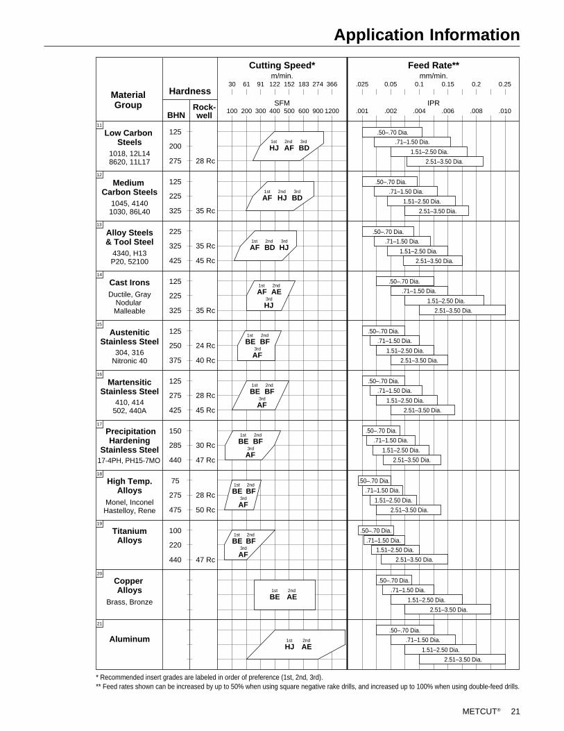
Application Information
MaterialGroup
Hardness
BHNRock-well
Cutting Speed*
SFM
Feed Rate**m/min.
30
Low Carbon Steels
1018, 12L148620, 11L17
125
200
275 28 Rc
Medium Carbon Steels
1045, 41401030, 86L40
125
225
325 35 Rc
AF BDHJ
HJ BDAF
Alloy Steels& Tool Steel
4340, H13P20, 52100
225
325
425 45 Rc
BD HJAF1st 2nd 3rd
35 Rc
1st 2nd 3rd
1st 2nd 3rd
61 91 122 152 183 274 366
100 200 300 400 500 600 900 1200
Cast IronsDuctile, Gray
Nodular Malleable
125
225
325 35 Rc
AF1st
AE2nd
HJ3rd
AusteniticStainless Steel
304, 316Nitronic 40
125
250
375 40 Rc
BE1st
BF2nd
AF3rd24 Rc
MartensiticStainless Steel
410, 414502, 440A
125
275
425 45 Rc
BE1st
BF2nd
AF3rd28 Rc
PrecipitationHardening
Stainless Steel17-4PH, PH15-7MO
150
285
440 47 Rc
BE1st
17
BF2nd
AF3rd30 Rc
High Temp.Alloys
75
275
475 50 Rc
BE1st
BF2nd
AF3rd28 Rc
Monel, InconelHastelloy, Rene
TitaniumAlloys
100
220
440 47 Rc
BE1st
BF2nd
AF3rd
Copper Alloys
BE1st
AE2nd
Brass, Bronze
AluminumHJ1st
AE2nd
IPR
mm/min..025 0.05 0.1 0.15
.001 .002 .004 .006
0.2
.008
0.25
.010
* Recommended insert grades are labeled in order of preference (1st, 2nd, 3rd).** Feed rates shown can be increased by up to 50% when using square negative rake drills, and increased up to 100% when using double-feed drills.
.50–.70 Dia.
.71–1.50 Dia.
1.51–2.50 Dia.
2.51–3.50 Dia.
.50–.70 Dia.
.71–1.50 Dia.
1.51–2.50 Dia.
2.51–3.50 Dia.
2.51–3.50 Dia.
.50–.70 Dia.
.71–1.50 Dia.
1.51–2.50 Dia.
2.51–3.50 Dia.
.50–.70 Dia.
.71–1.50 Dia.
1.51–2.50 Dia.
.50–.70 Dia.
2.51–3.50 Dia.
.71–1.50 Dia.
1.51–2.50 Dia.
.50–.70 Dia.
2.51–3.50 Dia.
.71–1.50 Dia.
1.51–2.50 Dia.
.50–.70 Dia.
2.51–3.50 Dia.
.71–1.50 Dia.
1.51–2.50 Dia.
.50–.70 Dia.
2.51–3.50 Dia.
.71–1.50 Dia.
1.51–2.50 Dia.
.50–.70 Dia.
2.51–3.50 Dia.
.71–1.50 Dia.
1.51–2.50 Dia.
.50–.70 Dia.
2.51–3.50 Dia.
.71–1.50 Dia.
1.51–2.50 Dia.
.50–.70 Dia.
2.51–3.50 Dia.
.71–1.50 Dia.
1.51–2.50 Dia.
18
19
20
21
16
15
14
13
12
11
22 METCUT®
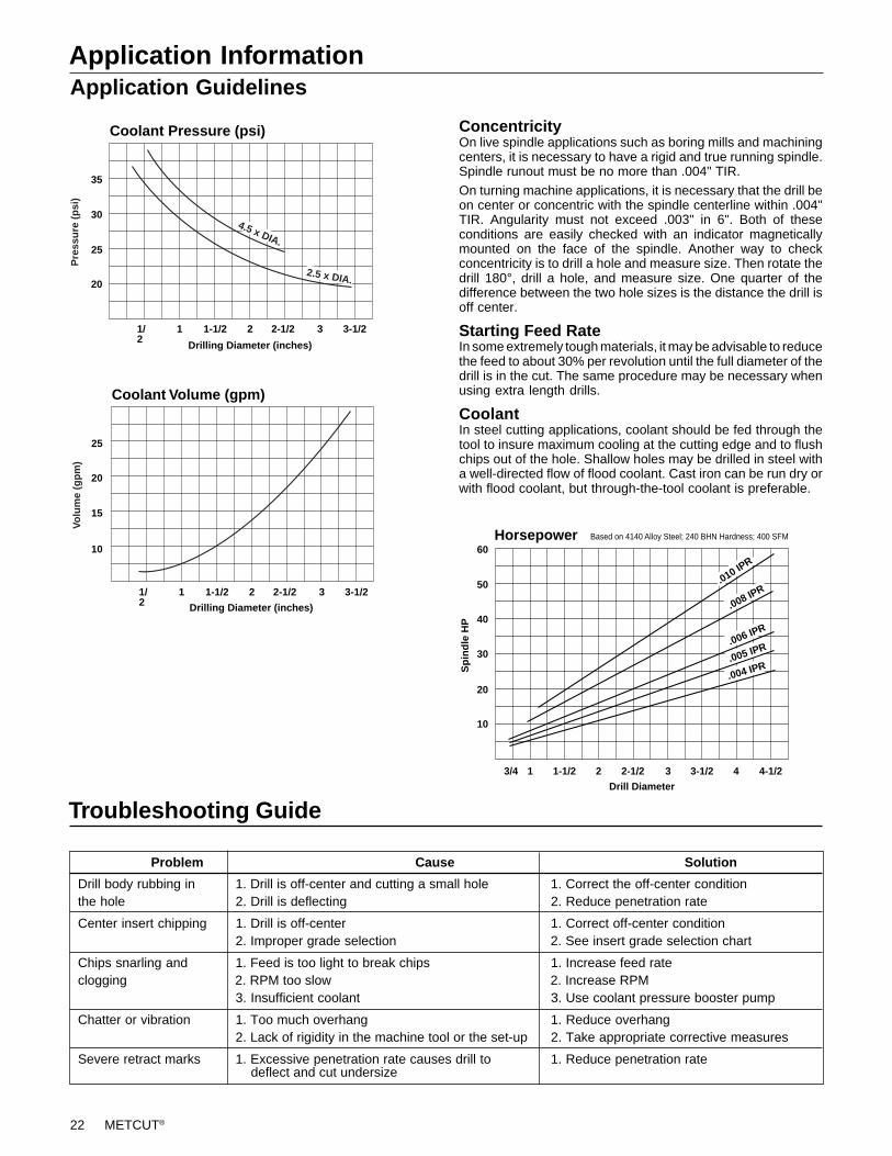
Application InformationApplication Guidelines
ConcentricityOn live spindle applications such as boring mills and machiningcenters, it is necessary to have a rigid and true running spindle.Spindle runout must be no more than .004" TIR.
On turning machine applications, it is necessary that the drill beon center or concentric with the spindle centerline within .004"TIR. Angularity must not exceed .003" in 6". Both of theseconditions are easily checked with an indicator magneticallymounted on the face of the spindle. Another way to checkconcentricity is to drill a hole and measure size. Then rotate thedrill 180°, drill a hole, and measure size. One quarter of thedifference between the two hole sizes is the distance the drill isoff center.
Starting Feed RateIn some extremely tough materials, it may be advisable to reducethe feed to about 30% per revolution until the full diameter of thedrill is in the cut. The same procedure may be necessary whenusing extra length drills.
CoolantIn steel cutting applications, coolant should be fed through thetool to insure maximum cooling at the cutting edge and to flushchips out of the hole. Shallow holes may be drilled in steel witha well-directed flow of flood coolant. Cast iron can be run dry orwith flood coolant, but through-the-tool coolant is preferable.
Troubleshooting Guide
Problem Cause Solution
Drill body rubbing in 1. Drill is off-center and cutting a small hole 1. Correct the off-center conditionthe hole 2. Drill is deflecting 2. Reduce penetration rate
Center insert chipping 1. Drill is off-center 1. Correct off-center condition2. Improper grade selection 2. See insert grade selection chart
Chips snarling and 1. Feed is too light to break chips 1. Increase feed rateclogging 2. RPM too slow 2. Increase RPM
3. Insufficient coolant 3. Use coolant pressure booster pump
Chatter or vibration 1. Too much overhang 1. Reduce overhang2. Lack of rigidity in the machine tool or the set-up 2. Take appropriate corrective measures
Severe retract marks 1. Excessive penetration rate causes drill to 1. Reduce penetration rate deflect and cut undersize
Horsepower60
50
40
30
20
10
3/4 1 1-1/2 2 2-1/2 3 3-1/2 4 4-1/2
.004 IPR.005 IPR.006 IPR
.008 IPR.010 IP
R
Sp
ind
le H
P
Drill Diameter
Based on 4140 Alloy Steel; 240 BHN Hardness; 400 SFM
1/2
1 1-1/2 2 2-1/2 3 3-1/2
20
25
30
35
Coolant Pressure (psi)
Drilling Diameter (inches)
Pre
ssu
re (
psi
)
2.5 x DIA.
4.5 x DIA.
10
15
20
25
Coolant Volume (gpm)
Drilling Diameter (inches)
Volu
me
(gp
m)
1/2
1 1-1/2 2 2-1/2 3 3-1/2
METCUT® 23
Reamers
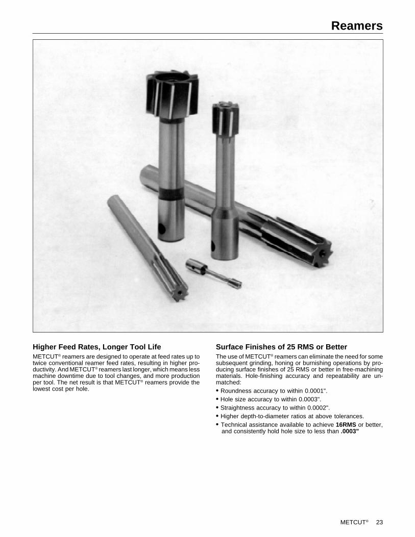
Higher Feed Rates, Longer Tool LifeMETCUT® reamers are designed to operate at feed rates up totwice conventional reamer feed rates, resulting in higher pro-ductivity. And METCUT® reamers last longer, which means lessmachine downtime due to tool changes, and more productionper tool. The net result is that METCUT® reamers provide thelowest cost per hole.
Surface Finishes of 25 RMS or BetterThe use of METCUT® reamers can eliminate the need for somesubsequent grinding, honing or burnishing operations by pro-ducing surface finishes of 25 RMS or better in free-machiningmaterials. Hole-finishing accuracy and repeatability are un-matched:• Roundness accuracy to within 0.0001".• Hole size accuracy to within 0.0003".• Straightness accuracy to within 0.0002".• Higher depth-to-diameter ratios at above tolerances.• Technical assistance available to achieve 16RMS or better, and consistently hold hole size to less than .0003"

24 METCUT®
Reamers
METCUT Reamers vs. Conventional Reamers –Performance Overview
METCUT reamers can produce surface finishes and size tolerancesotherwise achieved only through finish grinding, burnishing, or honing.
Finish – RMS
Drill
Size Tolerances
METCUT reamers provide significantly increased tool life and higherfeed rates.
Tool Life – Number of Holes
Feed Rate – IPR
METCUT reamers offer higher depth-to-diameter ratios at stated size,straightness and roundness tolerances.
Depth-to-Diameter Ratio
Drill Ream
METCUT
METCUT
METCUT
METCUT
METCUT
63 40 8
GrindDrill
125
Conventional Ream
0.001" 0.0003"
GrindDrill
0.003"
Conventional
Ream
Ream
5000 10,000 50,000+500 1000 2000
Conventional
.008 .010 .020 .030 .060+.002
Conventional
2:1 4:11:1 3:1
Conventional
Straight Portion
Nose
PrimaryChamfer
Chamfer
BackPortion
Straight PortionSingle Lead
Double Lead
BackTaper
Sharpening Profile
The profile form on the reamer is impor-tant in obtaining the best finish andlongest possible tool life.
METCUT offers two basic types of pro-files with our controlled CNC form typesharpening methods.
I. The Double Lead Profile for enhancedsurface finish. Following the primarychamfer, a nose section is blended intothe straight portion. The nose sectionremoves the feed marks prior to the finalsizing of the hole and provides a 25 to50 RMS finish.
II. Single Lead Profile for enhanced toollife where finish is not as critical. Thisprovides a profile of a chamfer tangentto the straight portion as shown in thediagram.
METCUT® 25
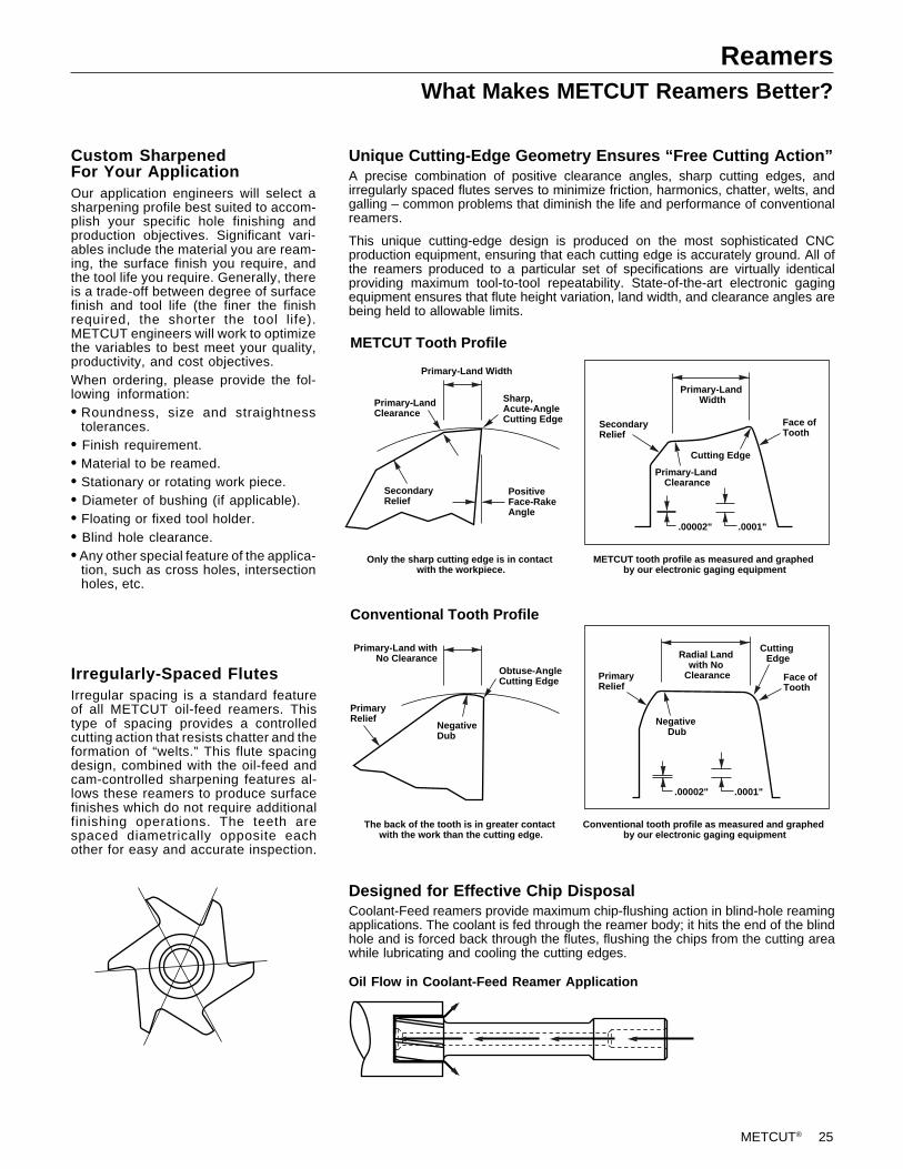
ReamersWhat Makes METCUT Reamers Better?
Custom SharpenedFor Your ApplicationOur application engineers will select asharpening profile best suited to accom-plish your specific hole finishing andproduction objectives. Significant vari-ables include the material you are ream-ing, the surface finish you require, andthe tool life you require. Generally, thereis a trade-off between degree of surfacefinish and tool life (the finer the finishrequired, the shorter the tool life).METCUT engineers will work to optimizethe variables to best meet your quality,productivity, and cost objectives.When ordering, please provide the fol-lowing information:• Roundness, size and straightness
tolerances.• Finish requirement.• Material to be reamed.• Stationary or rotating work piece.• Diameter of bushing (if applicable).• Floating or fixed tool holder.• Blind hole clearance.• Any other special feature of the applica-
tion, such as cross holes, intersectionholes, etc.
Unique Cutting-Edge Geometry Ensures “Free Cutting Action”A precise combination of positive clearance angles, sharp cutting edges, andirregularly spaced flutes serves to minimize friction, harmonics, chatter, welts, andgalling – common problems that diminish the life and performance of conventionalreamers.
This unique cutting-edge design is produced on the most sophisticated CNCproduction equipment, ensuring that each cutting edge is accurately ground. All ofthe reamers produced to a particular set of specifications are virtually identicalproviding maximum tool-to-tool repeatability. State-of-the-art electronic gagingequipment ensures that flute height variation, land width, and clearance angles arebeing held to allowable limits.
Designed for Effective Chip DisposalCoolant-Feed reamers provide maximum chip-flushing action in blind-hole reamingapplications. The coolant is fed through the reamer body; it hits the end of the blindhole and is forced back through the flutes, flushing the chips from the cutting areawhile lubricating and cooling the cutting edges.
Primary-Land Width
Sharp,Acute-AngleCutting Edge
METCUT Tooth Profile
Primary-Land Clearance
PositiveFace-RakeAngle
SecondaryRelief
Only the sharp cutting edge is in contact with the workpiece.
Primary-Land Width
SecondaryRelief
Primary-Land Clearance
Cutting Edge
Face ofTooth
.00002" .0001"
METCUT tooth profile as measured and graphed by our electronic gaging equipment
Conventional Tooth Profile
Primary-Land withNo Clearance
Obtuse-AngleCutting Edge
The back of the tooth is in greater contact with the work than the cutting edge.
PrimaryRelief
NegativeDub
Radial Land with No
ClearancePrimaryRelief
Negative Dub
Cutting Edge
Face ofTooth
.00002" .0001"
Conventional tooth profile as measured and graphed by our electronic gaging equipment
Oil Flow in Coolant-Feed Reamer Application
Irregularly-Spaced FlutesIrregular spacing is a standard featureof all METCUT oil-feed reamers. Thistype of spacing provides a controlledcutting action that resists chatter and theformation of “welts.” This flute spacingdesign, combined with the oil-feed andcam-controlled sharpening features al-lows these reamers to produce surfacefinishes which do not require additionalfinishing operations. The teeth arespaced diametrically opposite eachother for easy and accurate inspection.
26 METCUT®
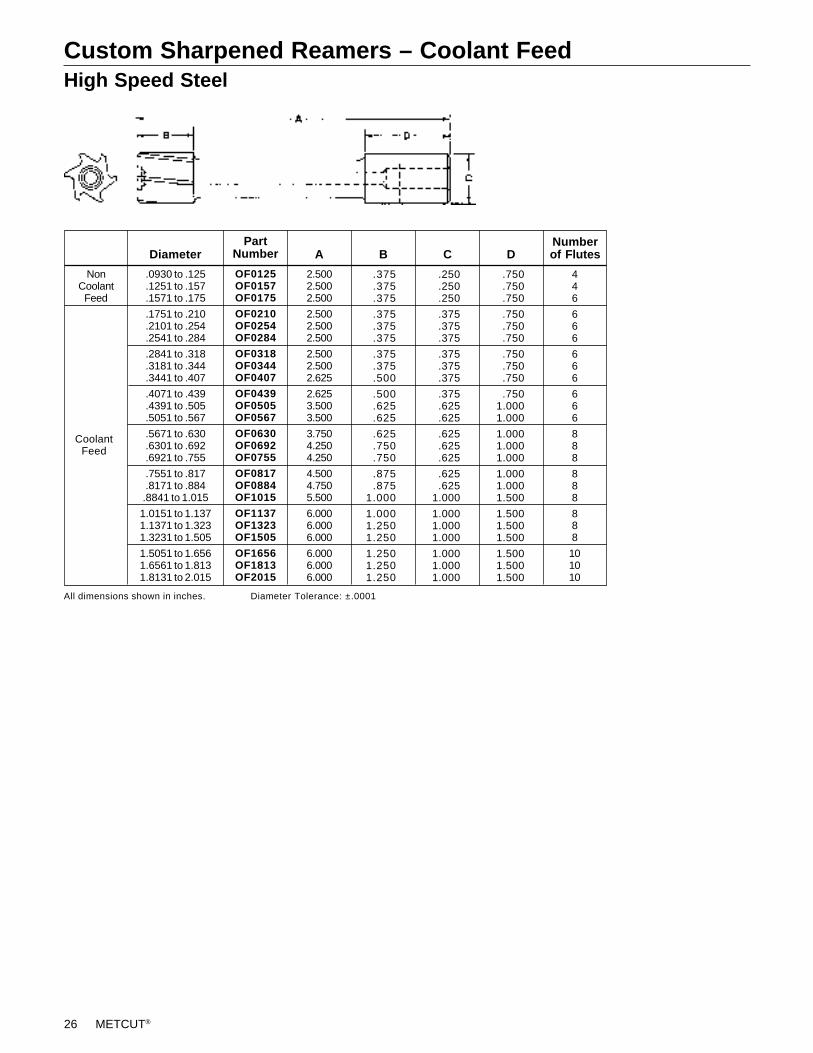
Custom Sharpened Reamers – Coolant FeedHigh Speed Steel
A B C DNumberof Flutes
All dimensions shown in inches. Diameter Tolerance: ±.0001
446
666
666
666
888
888
888
101010
2.5002.5002.500
2.5002.5002.500
2.5002.5002.625
2.6253.5003.500
3.7504.2504.250
4.5004.7505.500
6.0006.0006.000
6.0006.0006.000
NonCoolantFeed
CoolantFeed
Diameter
.0930 to .125
.1251 to .157
.1571 to .175
.1751 to .210
.2101 to .254
.2541 to .284
.2841 to .318
.3181 to .344
.3441 to .407
.4071 to .439
.4391 to .505
.5051 to .567
.5671 to .630
.6301 to .692
.6921 to .755
.7551 to .817
.8171 to .884.8841 to 1.015
1.0151 to 1.1371.1371 to 1.3231.3231 to 1.505
1.5051 to 1.6561.6561 to 1.8131.8131 to 2.015
PartNumber
OF0125OF0157OF0175
OF0210OF0254OF0284
OF0318OF0344OF0407
OF0439OF0505OF0567
OF0630OF0692OF0755
OF0817OF0884OF1015
OF1137OF1323OF1505
OF1656OF1813OF2015
.375
.375
.375
.375
.375
.375
.375
.375
.500
.500
.625
.625
.625
.750
.750
.875
.8751.000
1.0001.2501.250
1.2501.2501.250
.250
.250
.250
.375
.375
.375
.375
.375
.375
.375
.625
.625
.625
.625
.625
.625
.6251.000
1.0001.0001.000
1.0001.0001.000
.750
.750
.750
.750
.750
.750
.750
.750
.750
.7501.0001.000
1.0001.0001.000
1.0001.0001.500
1.5001.5001.500
1.5001.5001.500
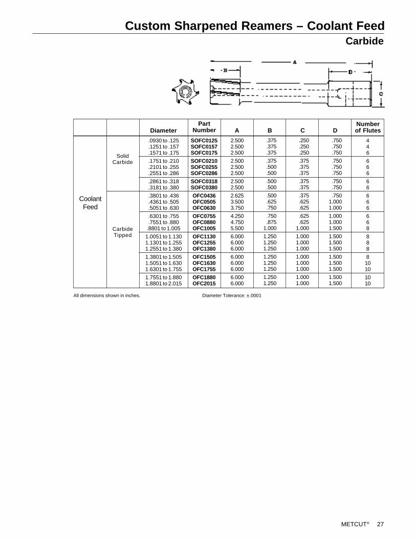
METCUT® 27
Custom Sharpened Reamers – Coolant FeedCarbide
A B C DNumberof Flutes
446
666
66
666
668
888
81010
1010
2.5002.5002.500
2.5002.5002.500
2.5002.500
2.6253.5003.750
4.2504.7505.500
6.0006.0006.000
6.0006.0006.000
6.0006.000
All dimensions shown in inches. Diameter Tolerance: ±.0001
SolidCarbide
CarbideTipped
Diameter
.0930 to .125
.1251 to .157
.1571 to .175
.1751 to .210
.2101 to .255
.2551 to .286
.2861 to .318
.3181 to .380
.3801 to .436
.4361 to .505
.5051 to .630
.6301 to .755
.7551 to .880.8801 to 1.005
1.0051 to 1.1301.1301 to 1.2551.2551 to 1.380
1.3801 to 1.5051.5051 to 1.6301.6301 to 1.755
1.7551 to 1.8801.8801 to 2.015
PartNumber
SOFC0125SOFC0157SOFC0175
SOFC0210SOFC0255SOFC0286
SOFC0318SOFC0380
OFC0436OFC0505OFC0630
OFC0755OFC0880OFC1005
OFC1130OFC1255OFC1380
OFC1505OFC1630OFC1755
OFC1880OFC2015
.375
.375
.375
.375
.500
.500
.500
.500
.500
.625
.750
.750
.8751.000
1.2501.2501.250
1.2501.2501.250
1.2501.250
.250
.250
.250
.375
.375
.375
.375
.375
.375
.625
.625
.625
.6251.000
1.0001.0001.000
1.0001.0001.000
1.0001.000
.750
.750
.750
.750
.750
.750
.750
.750
.7501.0001.000
1.0001.0001.500
1.5001.5001.500
1.5001.5001.500
1.5001.500
CoolantFeed
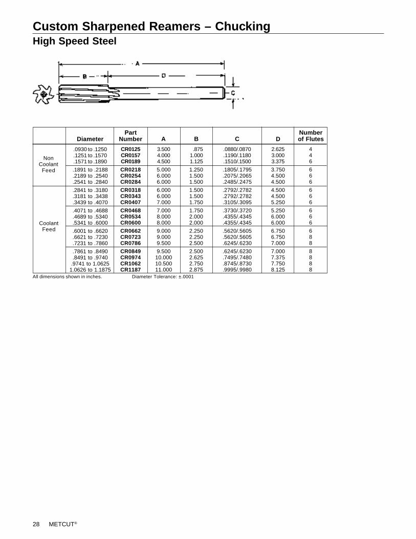
28 METCUT®
Custom Sharpened Reamers – ChuckingHigh Speed Steel
All dimensions shown in inches. Diameter Tolerance: ±.0001
A B C DNumberof Flutes
446
666
666
666
688
8888
2.6253.0003.375
3.7504.5004.500
4.5004.5005.250
5.2506.0006.000
6.7506.7507.000
7.0007.3757.7508.125
.0880/.0870
.1190/.1180
.1510/.1500
.1805/.1795
.2075/.2065
.2485/.2475
.2792/.2782
.2792/.2782
.3105/.3095
.3730/.3720
.4355/.4345
.4355/.4345
.5620/.5605
.5620/.5605
.6245/.6230
.6245/.6230
.7495/.7480
.8745/.8730
.9995/.9980
3.5004.0004.500
5.0006.0006.000
6.0006.0007.000
7.0008.0008.000
9.0009.0009.500
9.50010.00010.50011.000
Diameter
.0930 to .1250
.1251 to .1570
.1571 to .1890
.1891 to .2188
.2189 to .2540
.2541 to .2840
.2841 to .3180
.3181 to .3438
.3439 to .4070
.4071 to .4688
.4689 to .5340
.5341 to .6000
.6001 to .6620
.6621 to .7230
.7231 to .7860
.7861 to .8490
.8491 to .9740.9741 to 1.0625
1.0626 to 1.1875
CR0125CR0157CR0189
CR0218CR0254CR0284
CR0318CR0343CR0407
CR0468CR0534CR0600
CR0662CR0723CR0786
CR0849CR0974CR1062CR1187
PartNumber
.8751.0001.125
1.2501.5001.500
1.5001.5001.750
1.7502.0002.000
2.2502.2502.500
2.5002.6252.7502.875
NonCoolant
Feed
CoolantFeed
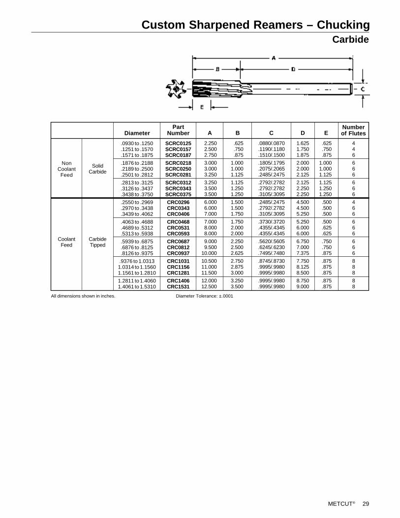
METCUT® 29
Custom Sharpened Reamers – ChuckingCarbide
Numberof FlutesE
446
666
666
466
666
666
888
88
.625
.750
.875
1.0001.0001.125
1.1251.2501.250
.500
.500
.500
.500
.625
.625
.750
.750
.875
.875
.875
.875
.875
.875
D
1.6251.7501.875
2.0002.0002.125
2.1252.2502.250
4.5004.5005.250
5.2506.0006.000
6.7507.0007.375
7.7508.1258.500
8.7509.000
.0880/.0870
.1190/.1180
.1510/.1500
.1805/.1795
.2075/.2065
.2485/.2475
.2792/.2782
.2792/.2782
.3105/.3095
.2485/.2475
.2792/.2782
.3105/.3095
.3730/.3720
.4355/.4345
.4355/.4345
.5620/.5605
.6245/.6230
.7495/.7480
.8745/.8730
.9995/.9980
.9995/.9980
.9995/.9980
.9995/.9980
CB
.625
.750
.875
1.0001.0001.125
1.1251.2501.250
1.5001.5001.750
1.7502.0002.000
2.2502.5002.625
2.7502.8753.000
3.2503.500
A
2.2502.5002.750
3.0003.0003.250
3.2503.5003.500
6.0006.0007.000
7.0008.0008.000
9.0009.500
10.000
10.50011.00011.500
12.00012.500
SCRC0125SCRC0157SCRC0187
SCRC0218SCRC0250SCRC0281
SCRC0312SCRC0343SCRC0375
CRC0296CRC0343CRC0406
CRC0468CRC0531CRC0593
CRC0687CRC0812CRC0937
CRC1031CRC1156CRC1281
CRC1406CRC1531
PartNumberDiameter
.0930 to .1250
.1251 to .1570
.1571 to .1875
.1876 to .2188
.2189 to .2500
.2501 to .2812
.2813 to .3125
.3126 to .3437
.3438 to .3750
.2550 to .2969
.2970 to .3438
.3439 to .4062
.4063 to .4688
.4689 to .5312
.5313 to .5938
.5939 to .6875
.6876 to .8125
.8126 to .9375
.9376 to 1.03131.0314 to 1.15601.1561 to 1.2810
1.2811 to 1.40601.4061 to 1.5310
SolidCarbide
CarbideTipped
CoolantFeed
NonCoolantFeed
All dimensions shown in inches. Diameter Tolerance: ±.0001
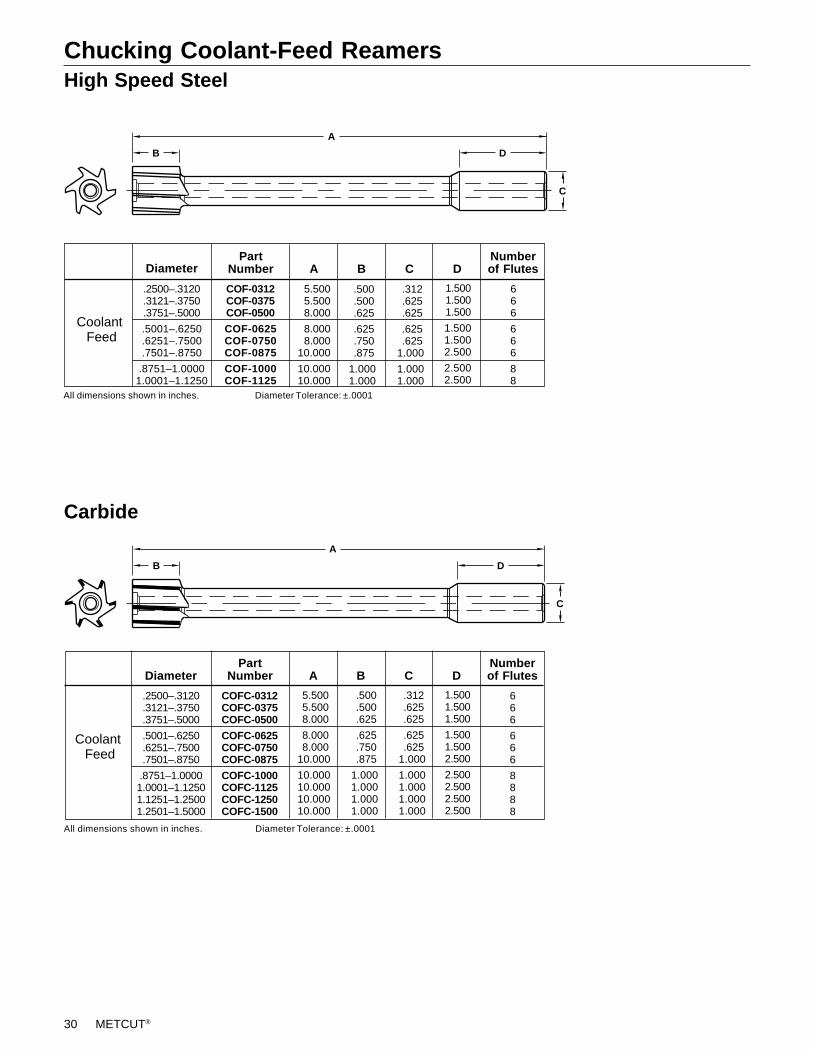
30 METCUT®
Chucking Coolant-Feed ReamersHigh Speed Steel
Carbide
Diameter
.2500–.3120
.3121–.3750
.3751–.5000
.5001–.6250
.6251–.7500
.7501–.8750
.8751–1.00001.0001–1.12501.1251–1.25001.2501–1.5000
A
5.500 5.500 8.000
8.000 8.00010.000
10.00010.00010.00010.000
B
.500 .500 .625
.625 .750 .875
1.0001.0001.0001.000
C
.312 .625 .625
.625 .6251.000
1.0001.0001.0001.000
D
666
666
8888
Numberof Flutes
1.5001.5001.500
1.5001.5002.500
2.5002.5002.5002.500
All dimensions shown in inches. Diameter Tolerance: ±.0001
COFC-0312COFC-0375COFC-0500
COFC-0625COFC-0750COFC-0875
COFC-1000COFC-1125COFC-1250COFC-1500
PartNumber
B
C
A
D
Diameter
.2500–.3120
.3121–.3750
.3751–.5000
.5001–.6250
.6251–.7500
.7501–.8750
.8751–1.00001.0001–1.1250
A
5.500 5.500 8.000
8.000 8.00010.000
10.00010.000
B
.500 .500 .625
.625 .750 .875
1.0001.000
C
.312 .625 .625
.625 .6251.000
1.0001.000
D
666
666
88
Numberof Flutes
1.5001.5001.500
1.5001.5002.500
2.5002.500
All dimensions shown in inches. Diameter Tolerance: ±.0001
COF-0312COF-0375COF-0500
COF-0625COF-0750COF-0875
COF-1000COF-1125
PartNumber
B
C
A
D
Coolant Feed
Coolant Feed
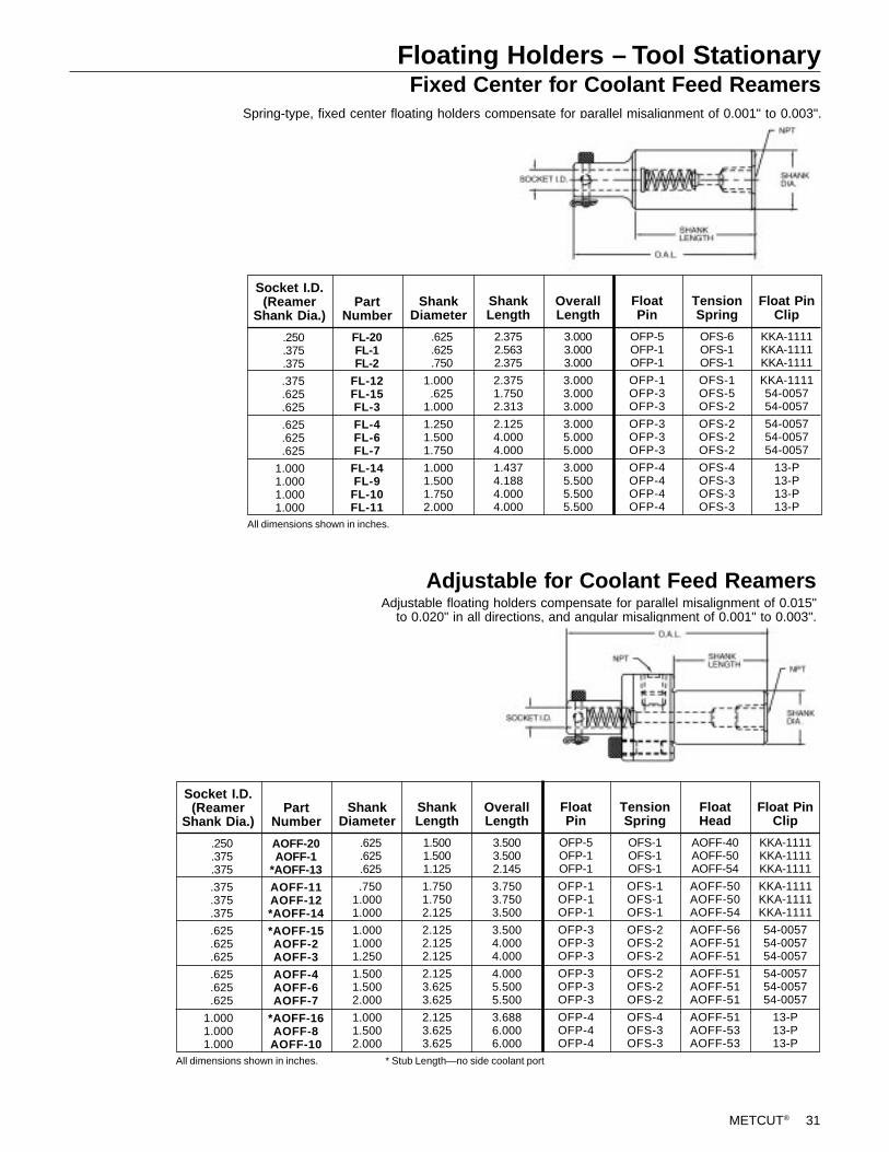
METCUT® 31
Floating Holders – Tool StationaryFixed Center for Coolant Feed Reamers
Spring-type, fixed center floating holders compensate for parallel misalignment of 0.001" to 0.003".
Adjustable for Coolant Feed ReamersAdjustable floating holders compensate for parallel misalignment of 0.015"
to 0.020" in all directions, and angular misalignment of 0.001" to 0.003".
OFS-6OFS-1OFS-1
OFS-1OFS-5OFS-2
OFS-2OFS-2OFS-2
OFS-4OFS-3OFS-3OFS-3
ShankDiameter
ShankLength
2.3752.5632.375
2.3751.7502.313
2.1254.0004.000
1.4374.1884.0004.000
OverallLength
3.0003.0003.000
3.0003.0003.000
3.0005.0005.000
3.0005.5005.5005.500
Socket I.D.(Reamer
Shank Dia.)Part
NumberFloatPin
OFP-5OFP-1OFP-1
OFP-1OFP-3OFP-3
OFP-3OFP-3OFP-3
OFP-4OFP-4OFP-4OFP-4
TensionSpring
All dimensions shown in inches.
.250
.375
.375
.375
.625
.625
.625
.625
.625
1.0001.0001.0001.000
.625
.625
.750
1.000.625
1.000
1.2501.5001.750
1.0001.5001.7502.000
KKA-1111KKA-1111KKA-1111
KKA-111154-005754-0057
54-005754-005754-0057
13-P13-P13-P13-P
Float PinClip
FL-20FL-1FL-2
FL-12FL-15FL-3
FL-4FL-6FL-7
FL-14FL-9
FL-10FL-11
FloatHead
AOFF-40AOFF-50AOFF-54
AOFF-50AOFF-50AOFF-54
AOFF-56AOFF-51AOFF-51
AOFF-51AOFF-51AOFF-51
AOFF-51AOFF-53AOFF-53
ShankDiameter
ShankLength
1.5001.5001.125
1.7501.7502.125
2.1252.1252.125
2.1253.6253.625
2.1253.6253.625
OverallLength
3.5003.5002.145
3.7503.7503.500
3.5004.0004.000
4.0005.5005.500
3.6886.0006.000
Socket I.D.(Reamer
Shank Dia.)Part
NumberFloatPin
OFP-5OFP-1OFP-1
OFP-1OFP-1OFP-1
OFP-3OFP-3OFP-3
OFP-3OFP-3OFP-3
OFP-4OFP-4OFP-4
TensionSpring
OFS-1OFS-1OFS-1
OFS-1OFS-1OFS-1
OFS-2OFS-2OFS-2
OFS-2OFS-2OFS-2
OFS-4OFS-3OFS-3
All dimensions shown in inches.
.250
.375
.375
.375
.375
.375
.625
.625
.625
.625
.625
.625
1.0001.0001.000
.625
.625
.625
.7501.0001.000
1.0001.0001.250
1.5001.5002.000
1.0001.5002.000
KKA-1111KKA-1111KKA-1111
KKA-1111KKA-1111KKA-1111
54-005754-005754-0057
54-005754-005754-0057
13-P13-P13-P
Float PinClip
AOFF-20AOFF-1
*AOFF-13
AOFF-11AOFF-12*AOFF-14
*AOFF-15AOFF-2AOFF-3
AOFF-4AOFF-6AOFF-7
*AOFF-16AOFF-8AOFF-10
* Stub Length—no side coolant port
32 METCUT®
Coolant-Through Floating Holders – Tool Rotatingfor Chucking or Coolant Feed Reamers
Collets for Coolant-Through Floating Holders
These compact floating holders utilize an anti-friction dual Oldham coupling mechanismand will compensate for radial misalignment of .062" in all directions.
G
A
BF
E
C D
ReamerRange Model GFEDCB
3.003.00
3.003.50
3.50
4.004.00
AAA-0625AA-0750
AB-0750AB-1000
AC-1000
AD-1250AD-1500
Part Number
AA
AB
AC
AD
.0930 to .2840
.1251 to .6000
.1251 to .9740
.2541 to 2.015
All dimensions shown in inches. Note: Order collets separately; See table below.
.625
.750
.7501.000
1.000
1.2501.500
1.061.06
1.691.69
2.19
2.692.69
.68 .74
1.251.35
1.94
2.502.50
1.941.94
2.312.31
3.50
3.623.62
1.091.09
1.693.62
2.75
2.752.75
AB-119
AB-151
AB-181
AB-208
AB-250
AB-281
AB-312
AB-375
AB-437
AB-181-S
AB-208-S
AB-250-S
AB-281-S
AB-312-S
AB-375-S
AB-437-S
AC-119
AC-151
AC-181
AC-208
AC-250
AC-281
AC-312
AC-375
AC-437
AC-562
AC-625
AC-750
AC-312-S
AC-375-S
AC-437-S
AC-562-S
AC-625-S
AC-750-S
AD-250
AD-281
AD-312
AD-375
AD-437
AD-562
AD-625
AD-750
AD-875
AD-1000
AD-250-S
AD-281-S
AD-312-S
AD-375-S
AD-437-S
AD-562-S
AD-625-S
AD-750-S
AD-875-S
AD-1000-S
Collet Part No.for Model AC
Collet Part No.for Model AB
Sealed SealedUnsealedUnsealed
Collet Part No.for Model AD
Unsealed SealedColletSize
.088
.119
.151
.181
.208
.250
.281
.312
.375
.437
.562
.625
.750
.875
1.000
AA-088
AA-119
AA-151
AA-181
AA-208
AA-250
Collet Part No.for Model AA
Unsealed
All dimensions shown in inches.Unsealed collets have a .020 in. collapse range.Sealed collets have a .004 in. collapse range.
Wrench
AAW
ABW
ACW
ADW
.87
.87
1.031.03
1.97
2.032.03

METCUT® 33
Collet Assemblyfor Coolant-Through Floating Holders
Collets must be assembled to the nut before inserting collet into chuck. Toassemble collet to nut, stand collet on end on any firm surface, nose up.Place nut over collet (Figure 1). Push down on nut with palm (Figure 2). Thecollet nose will collapse slightly, allowing it to enter the nut.
To remove collet from nut, hold the nut firmly in one hand and grasp thecollet with the other (Figure 3). Apply a bending pressure until nutseparates from collet (Figure 4). On smaller size collets (1/4, 3/8, and 1/2) where the collet nose projects beyond the nut, the nut can be removedby setting the collet/nut assembly nose down on a firm surface andpressing down on the nut until the collet disengages.
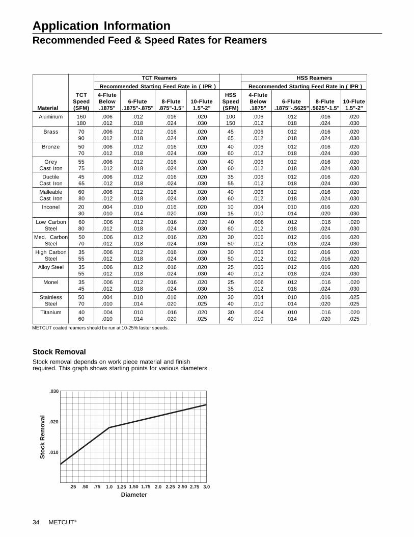
34 METCUT®
Application InformationRecommended Feed & Speed Rates for Reamers
TCT Reamers HSS Reamers
Recommended Starting Feed Rate in ( IPR ) Recommended Starting Feed Rate in ( IPR )
TCT 4-Flute HSS 4-FluteSpeed Below 6-Flute 8-Flute 10-Flute Speed Below 6-Flute 8-Flute 10-Flute
Material (SFM) .1875" .1875"-.875" .875"-1.5" 1.5"-2" (SFM) .1875" .1875"-.5625" .5625"-1.5" 1.5"-2"
Aluminum 160 .006 .012 .016 .020 100 .006 .012 .016 .020180 .012 .018 .024 .030 150 .012 .018 .024 .030
Brass 70 .006 .012 .016 .020 45 .006 .012 .016 .02090 .012 .018 .024 .030 65 .012 .018 .024 .030
Bronze 50 .006 .012 .016 .020 40 .006 .012 .016 .02070 .012 .018 .024 .030 60 .012 .018 .024 .030
Grey 55 .006 .012 .016 .020 40 .006 .012 .016 .020Cast Iron 75 .012 .018 .024 .030 60 .012 .018 .024 .030
Ductile 45 .006 .012 .016 .020 35 .006 .012 .016 .020Cast Iron 65 .012 .018 .024 .030 55 .012 .018 .024 .030
Malleable 60 .006 .012 .016 .020 40 .006 .012 .016 .020Cast Iron 80 .012 .018 .024 .030 60 .012 .018 .024 .030
Inconel 20 .004 .010 .016 .020 10 .004 .010 .016 .02030 .010 .014 .020 .030 15 .010 .014 .020 .030
Low Carbon 60 .006 .012 .016 .020 40 .006 .012 .016 .020Steel 80 .012 .018 .024 .030 60 .012 .018 .024 .030
Med. Carbon 50 .006 .012 .016 .020 30 .006 .012 .016 .020Steel 70 .012 .018 .024 .030 50 .012 .018 .024 .030
High Carbon 35 .006 .012 .016 .020 30 .006 .012 .016 .020Steel 55 .012 .018 .024 .030 50 .012 .012 .016 .020
Alloy Steel 35 .006 .012 .016 .020 25 .006 .012 .016 .02055 .012 .018 .024 .030 40 .012 .018 .024 .030
Monel 35 .006 .012 .016 .020 25 .006 .012 .016 .02045 .012 .018 .024 .030 35 .012 .018 .024 .030
Stainless 50 .004 .010 .016 .020 30 .004 .010 .016 .025Steel 70 .010 .014 .020 .025 40 .010 .014 .020 .025
Titanium 40 .004 .010 .016 .020 30 .004 .010 .016 .02060 .010 .014 .020 .025 40 .010 .014 .020 .025
Stock RemovalStock removal depends on work piece material and finishrequired. This graph shows starting points for various diameters.
.030
.020
.010
Sto
ck R
emov
al
.25 .50 1.0 1.25 1.50 1.75.75 2.0 2.25 2.50 2.75 3.0
Diameter
METCUT coated reamers should be run at 10-25% faster speeds.
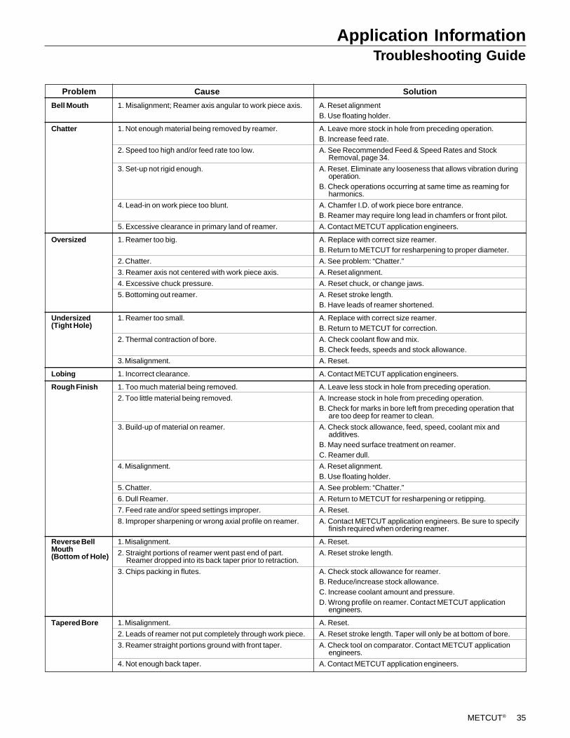
METCUT® 35
Bell Mouth
Chatter
Oversized
Undersized(Tight Hole)
Lobing
Rough Finish
Reverse BellMouth(Bottom of Hole)
Tapered Bore
Application InformationTroubleshooting Guide
A. Reset alignmentB. Use floating holder.
A. Leave more stock in hole from preceding operation.B. Increase feed rate.
A. See Recommended Feed & Speed Rates and StockRemoval, page 34.
A. Reset. Eliminate any looseness that allows vibration duringoperation.
B. Check operations occurring at same time as reaming forharmonics.
A. Chamfer I.D. of work piece bore entrance.B. Reamer may require long lead in chamfers or front pilot.
A. Contact METCUT application engineers.
A. Replace with correct size reamer.B. Return to METCUT for resharpening to proper diameter.
A. See problem: “Chatter.”
A. Reset alignment.
A. Reset chuck, or change jaws.
A. Reset stroke length.B. Have leads of reamer shortened.
A. Replace with correct size reamer.B. Return to METCUT for correction.
A. Check coolant flow and mix.B. Check feeds, speeds and stock allowance.
A. Reset.
A. Contact METCUT application engineers.
A. Leave less stock in hole from preceding operation.
A. Increase stock in hole from preceding operation.B. Check for marks in bore left from preceding operation that
are too deep for reamer to clean.
A. Check stock allowance, feed, speed, coolant mix andadditives.
B. May need surface treatment on reamer.C. Reamer dull.
A. Reset alignment.B. Use floating holder.
A. See problem: “Chatter.”
A. Return to METCUT for resharpening or retipping.
A. Reset.
A. Contact METCUT application engineers. Be sure to specifyfinish required when ordering reamer.
A. Reset.
A. Reset stroke length.
A. Check stock allowance for reamer.B. Reduce/increase stock allowance.C. Increase coolant amount and pressure.D. Wrong profile on reamer. Contact METCUT application
engineers.
A. Reset.
A. Reset stroke length. Taper will only be at bottom of bore.
A. Check tool on comparator. Contact METCUT applicationengineers.
A. Contact METCUT application engineers.
Cause Solution
1. Misalignment; Reamer axis angular to work piece axis.
1. Not enough material being removed by reamer.
2. Speed too high and/or feed rate too low.
3. Set-up not rigid enough.
4. Lead-in on work piece too blunt.
5. Excessive clearance in primary land of reamer.
1. Reamer too big.
2. Chatter.
3. Reamer axis not centered with work piece axis.
4. Excessive chuck pressure.
5. Bottoming out reamer.
1. Reamer too small.
2. Thermal contraction of bore.
3. Misalignment.
1. Incorrect clearance.
1. Too much material being removed.
2. Too little material being removed.
3. Build-up of material on reamer.
4. Misalignment.
5. Chatter.
6. Dull Reamer.
7. Feed rate and/or speed settings improper.
8. Improper sharpening or wrong axial profile on reamer.
1. Misalignment.
2. Straight portions of reamer went past end of part.Reamer dropped into its back taper prior to retraction.
3. Chips packing in flutes.
1. Misalignment.
2. Leads of reamer not put completely through work piece.
3. Reamer straight portions ground with front taper.
4. Not enough back taper.
Problem
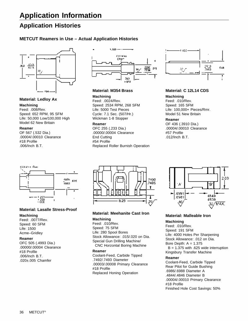
36 METCUT®
Application InformationApplication Histories
METCUT Reamers in Use – Actual Application Histories
Material: Ledloy AxMachiningFeed: .008/Rev.Speed: 652 RPM, 95 SFMLife: 50,000 Low/100,000 HighModel 62 New Britain
ReamerOF 567 (.532 Dia.).00004/.00010 Clearance#18 Profile.006/Inch B.T.
Material: M354 BrassMachiningFeed: .0024/Rev.Speed: 2534 RPM, 268 SFMLife: 5000 Test PiecesCycle: 7.1 Sec. (507/Hr.)Wickman 1-8 Stopper
ReamerOFC 255 (.233 Dia.).00000/.00004 ClearanceEnd Cutting#54 ProfileReplaced Roller Burnish Operation
Material: C 12L14 CDSMachiningFeed: .010/Rev.Speed: 165 SFMLife: 100,000+ Pieces/Rmr.Model 51 New Britain
ReamerOF 436 (.3910 Dia.).00004/.00010 Clearance#57 Profile.012/Inch B.T.
Material: Lasalle Stress-ProofMachiningFeed: .0077/Rev.Speed: 60 SFMLife: 1500Acme–Gridley
ReamerOFC 505 (.4993 Dia.).00000/.00004 Clearance#18 Profile.006/Inch B.T..020±.005 Chamfer
Material: Meehanite Cast IronMachiningFeed: .010/Rev.Speed: 75 SFMLife: 280 Spool BoresStock Allowance: .015/.020 on Dia.Special Gun Drilling Machine/
CNC Horzontal Boring Machine
ReamerCoolant-Feed, Carbide Tipped.7492/.7493 Diameter.00003/.00008 Primary Clearance#18 ProfileReplaced Honing Operation
Material: Malleable IronMachiningFeed: .010/Rev.Speed: 191 SFMLife: 4000 Holes Per SharpeningStock Allowance: .012 on Dia.Bore Depth: A = 1.375
B = 1.375 with .625 wide interruptionKingsbury Transfer Machine
ReamerCoolant-Feed, Carbide TippedRear Pilot for Guide Bushing.6986/.6988 Diameter A.4844/.4846 Diameter B.00004/.00010 Primary Clearance#18 ProfileFinished Hole Cost Savings: 50%
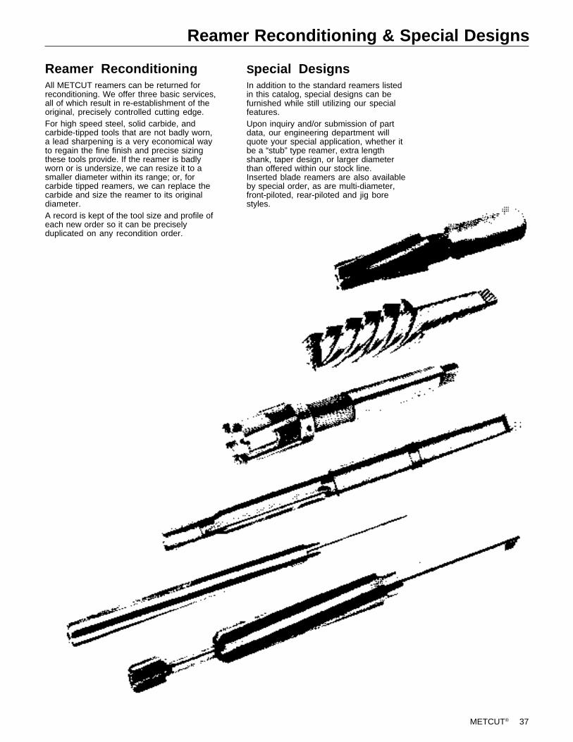
METCUT® 37
Reamer Reconditioning & Special Designs
Reamer ReconditioningAll METCUT reamers can be returned forreconditioning. We offer three basic services,all of which result in re-establishment of theoriginal, precisely controlled cutting edge.For high speed steel, solid carbide, andcarbide-tipped tools that are not badly worn,a lead sharpening is a very economical wayto regain the fine finish and precise sizingthese tools provide. If the reamer is badlyworn or is undersize, we can resize it to asmaller diameter within its range; or, forcarbide tipped reamers, we can replace thecarbide and size the reamer to its originaldiameter.A record is kept of the tool size and profile ofeach new order so it can be preciselyduplicated on any recondition order.
Special DesignsIn addition to the standard reamers listedin this catalog, special designs can befurnished while still utilizing our specialfeatures.Upon inquiry and/or submission of partdata, our engineering department willquote your special application, whether itbe a “stub” type reamer, extra lengthshank, taper design, or larger diameterthan offered within our stock line.Inserted blade reamers are also availableby special order, as are multi-diameter,front-piloted, rear-piloted and jig borestyles.

38 METCUT®
Reamer QuestionnaireTo help us provide you with the best reamer for your applicationplease complete this questionnaire and include a copy of it with your inquiry or order.
Your Name: Your Title:
Company: Phone:
Size & Tolerance of Hole:
Material: Brinell Hardness at Ream:
Machine:
Blind or Through Hole: Amount of Blind Hole Clearance:
Speed: RPM:
SFM: Feed:
Does Machine have Accelerated Feed Attachment?
Previous Operation (does reamer follow drill, boring bar, or rough reamer?)
Finish Stock Removal:
Reamer Floated? Holder Shank Diameter:
Coolant (available to reamer):
Coolant Type (oil, synthetic):
Finish Requirement:
Work Piece Stationary or Rotating:
Depth of Bore: Length of Cut:
Comments or Sketch of Bore:
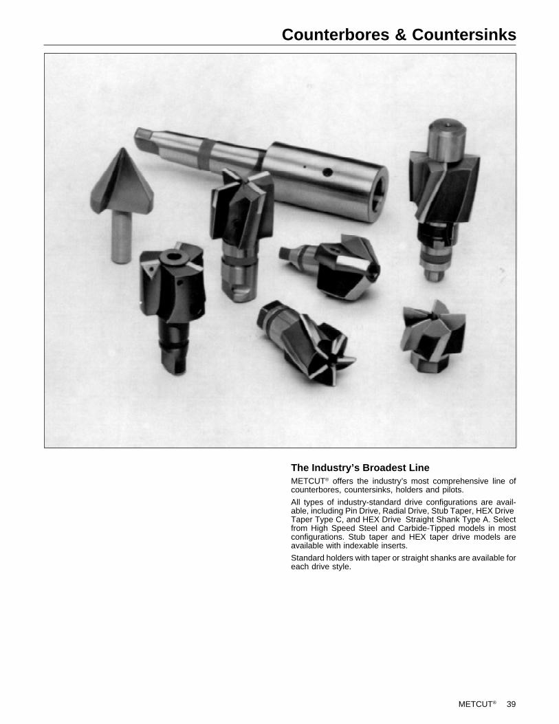
METCUT® 39
Counterbores & Countersinks
The Industry’s Broadest LineMETCUT® offers the industry’s most comprehensive line ofcounterbores, countersinks, holders and pilots.
All types of industry-standard drive configurations are avail-able, including Pin Drive, Radial Drive, Stub Taper, HEX DriveTaper Type C, and HEX Drive Straight Shank Type A. Selectfrom High Speed Steel and Carbide-Tipped models in mostconfigurations. Stub taper and HEX taper drive models areavailable with indexable inserts.
Standard holders with taper or straight shanks are available foreach drive style.
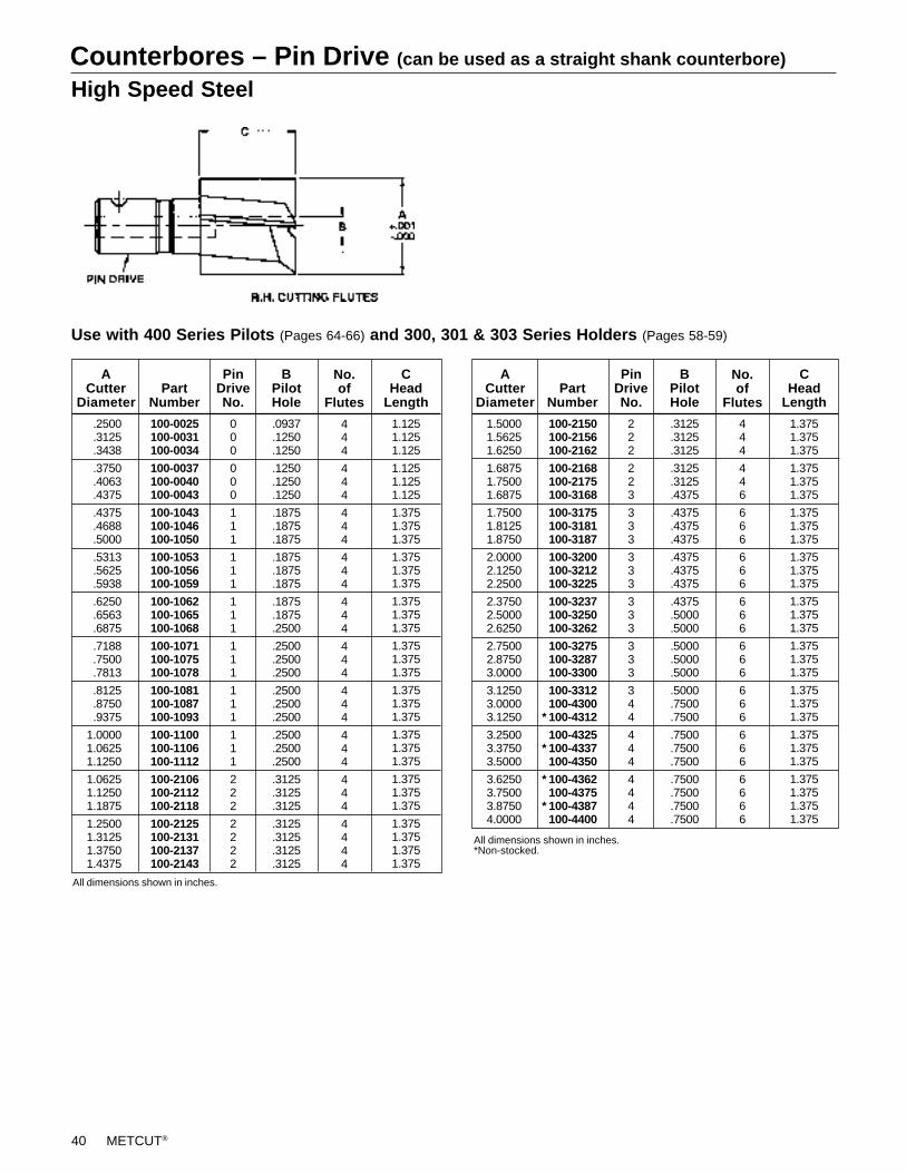
40 METCUT®
Counterbores – Pin Drive (can be used as a straight shank counterbore)
High Speed Steel
All dimensions shown in inches.*Non-stocked.
Use with 400 Series Pilots (Pages 64-66) and 300, 301 & 303 Series Holders (Pages 58-59)
All dimensions shown in inches.
1.3751.3751.375
1.3751.3751.375
1.3751.3751.375
1.3751.3751.375
1.3751.3751.375
1.3751.3751.375
1.3751.3751.375
1.3751.3751.375
1.3751.3751.3751.375
CHead
Length
BPilotHole
No.of
Flutes
444
446
666
666
666
666
666
666
6666
.3125
.3125
.3125
.3125
.3125
.4375
.4375
.4375
.4375
.4375
.4375
.4375
.4375
.5000
.5000
.5000
.5000
.5000
.5000
.7500
.7500
.7500
.7500
.7500
.7500
.7500
.7500
.7500
222
223
333
333
333
333
344
444
4444
PinDriveNo.
1.50001.56251.6250
1.68751.75001.6875
1.75001.81251.8750
2.00002.12502.2500
2.37502.50002.6250
2.75002.87503.0000
3.12503.00003.1250
3.25003.37503.5000
3.62503.75003.87504.0000
ACutter
Diameter
100-2150100-2156100-2162
100-2168100-2175100-3168
100-3175100-3181100-3187
100-3200100-3212100-3225
100-3237100-3250100-3262
100-3275100-3287100-3300
100-3312100-4300100-4312
100-4325100-4337100-4350
100-4362100-4375100-4387100-4400
PartNumber
*
*
*
*
BPilotHole
444
444
444
444
444
444
444
444
444
4444
No.of
Flutes
1.1251.1251.125
1.1251.1251.125
1.3751.3751.375
1.3751.3751.375
1.3751.3751.375
1.3751.3751.375
1.3751.3751.375
1.3751.3751.375
1.3751.3751.375
1.3751.3751.3751.375
CHead
Length
PinDriveNo.
000
000
111
111
111
111
111
111
222
2222
.0937
.1250
.1250
.1250
.1250
.1250
.1875
.1875
.1875
.1875
.1875
.1875
.1875
.1875
.2500
.2500
.2500
.2500
.2500
.2500
.2500
.2500
.2500
.2500
.3125
.3125
.3125
.3125
.3125
.3125
.3125
ACutter
DiameterPart
Number
100-0025100-0031100-0034
100-0037100-0040100-0043
100-1043100-1046100-1050
100-1053100-1056100-1059
100-1062100-1065100-1068
100-1071100-1075100-1078
100-1081100-1087100-1093
100-1100100-1106100-1112
100-2106100-2112100-2118
100-2125100-2131100-2137100-2143
.2500
.3125
.3438
.3750
.4063
.4375
.4375
.4688
.5000
.5313
.5625
.5938
.6250
.6563
.6875
.7188
.7500
.7813
.8125
.8750
.9375
1.00001.06251.1250
1.06251.12501.1875
1.25001.31251.37501.4375
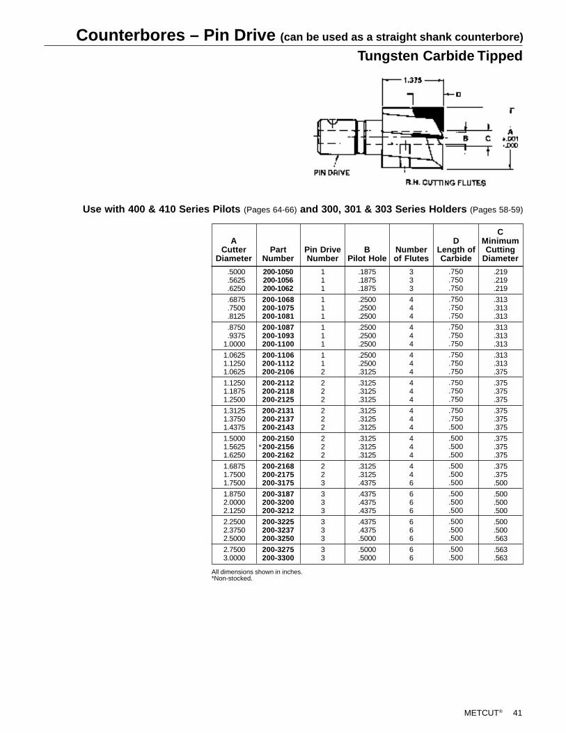
METCUT® 41
Counterbores – Pin Drive (can be used as a straight shank counterbore)
Tungsten Carbide Tipped
Use with 400 & 410 Series Pilots (Pages 64-66) and 300, 301 & 303 Series Holders (Pages 58-59)
.219
.219
.219
.313
.313
.313
.313
.313
.313
.313
.313
.375
.375
.375
.375
.375
.375
.375
.375
.375
.375
.375
.375
.500
.500
.500
.500
.500
.500
.563
.563
.563
CMinimumCutting
Diameter
.750
.750
.750
.750
.750
.750
.750
.750
.750
.750
.750
.750
.750
.750
.750
.750
.750
.500
.500
.500
.500
.500
.500
.500
.500
.500
.500
.500
.500
.500
.500
.500
DLength ofCarbide
Numberof Flutes
333
444
444
444
444
444
444
446
666
666
66
BPilot Hole
.1875
.1875
.1875
.2500
.2500
.2500
.2500
.2500
.2500
.2500
.2500
.3125
.3125
.3125
.3125
.3125
.3125
.3125
.3125
.3125
.3125
.3125
.3125
.4375
.4375
.4375
.4375
.4375
.4375
.5000
.5000
.5000
111
111
111
112
222
222
222
223
333
333
33
Pin DriveNumber
PartNumber
200-1050200-1056200-1062
200-1068200-1075200-1081
200-1087200-1093200-1100
200-1106200-1112200-2106
200-2112200-2118200-2125
200-2131200-2137200-2143
200-2150200-2156200-2162
200-2168200-2175200-3175
200-3187200-3200200-3212
200-3225200-3237200-3250
200-3275200-3300
ACutter
Diameter
All dimensions shown in inches.*Non-stocked.
.5000
.5625
.6250
.6875
.7500
.8125
.8750
.93751.0000
1.06251.12501.0625
1.12501.18751.2500
1.31251.37501.4375
1.50001.56251.6250
1.68751.75001.7500
1.87502.00002.1250
2.25002.37502.5000
2.75003.0000
*
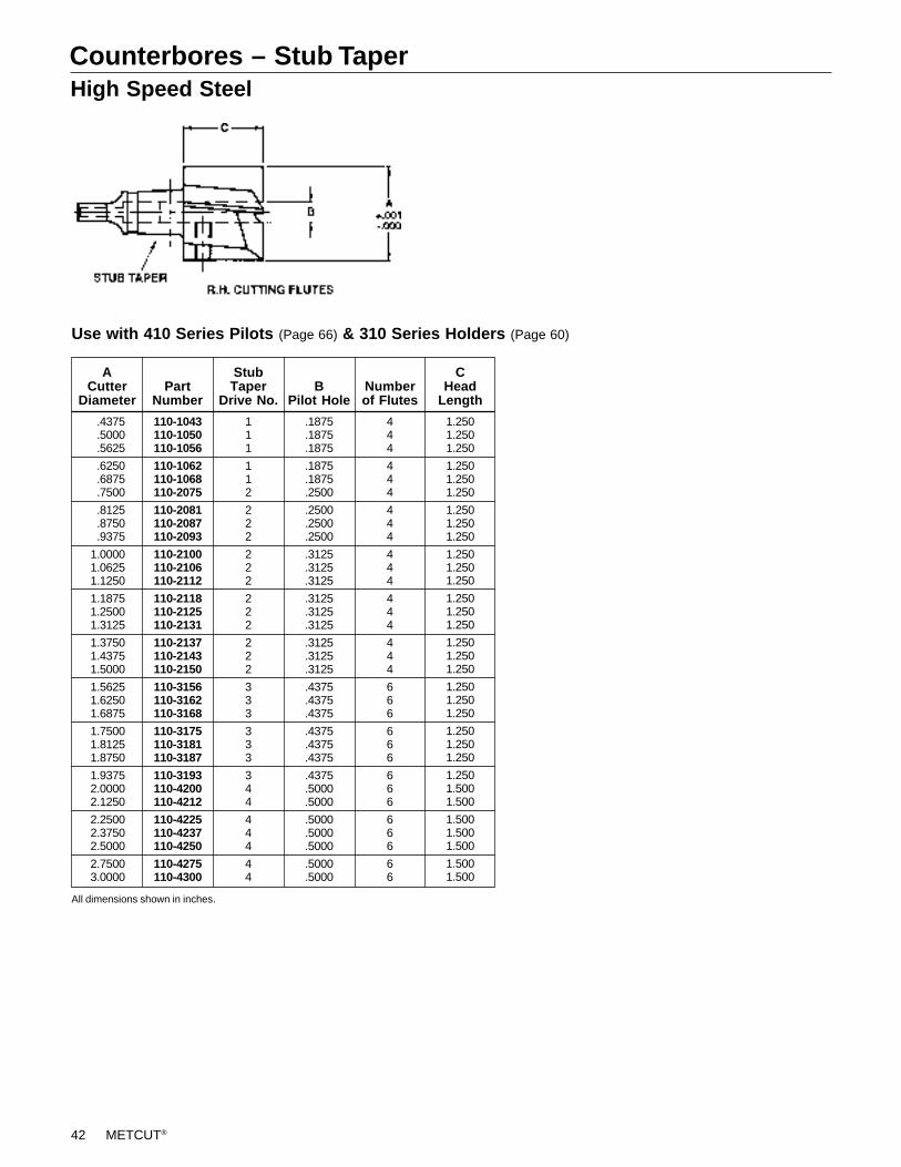
42 METCUT®
Counterbores – Stub TaperHigh Speed Steel
Use with 410 Series Pilots (Page 66) & 310 Series Holders (Page 60)
ACutter
Diameter
All dimensions shown in inches.
110-1043110-1050110-1056
110-1062110-1068110-2075
110-2081110-2087110-2093
110-2100110-2106110-2112
110-2118110-2125110-2131
110-2137110-2143110-2150
110-3156110-3162110-3168
110-3175110-3181110-3187
110-3193110-4200110-4212
110-4225110-4237110-4250
110-4275110-4300
111
112
222
222
222
222
333
333
344
444
44
StubTaper
Drive No.B
Pilot Hole
.1875
.1875
.1875
.1875
.1875
.2500
.2500
.2500
.2500
.3125
.3125
.3125
.3125
.3125
.3125
.3125
.3125
.3125
.4375
.4375
.4375
.4375
.4375
.4375
.4375
.5000
.5000
.5000
.5000
.5000
.5000
.5000
Numberof Flutes
444
444
444
444
444
444
666
666
666
666
66
1.2501.2501.250
1.2501.2501.250
1.2501.2501.250
1.2501.2501.250
1.2501.2501.250
1.2501.2501.250
1.2501.2501.250
1.2501.2501.250
1.2501.5001.500
1.5001.5001.500
1.5001.500
CHead
LengthPart
Number
.4375
.5000
.5625
.6250
.6875
.7500
.8125
.8750
.9375
1.00001.06251.1250
1.18751.25001.3125
1.37501.43751.5000
1.56251.62501.6875
1.75001.81251.8750
1.93752.00002.1250
2.25002.37502.5000
2.75003.0000
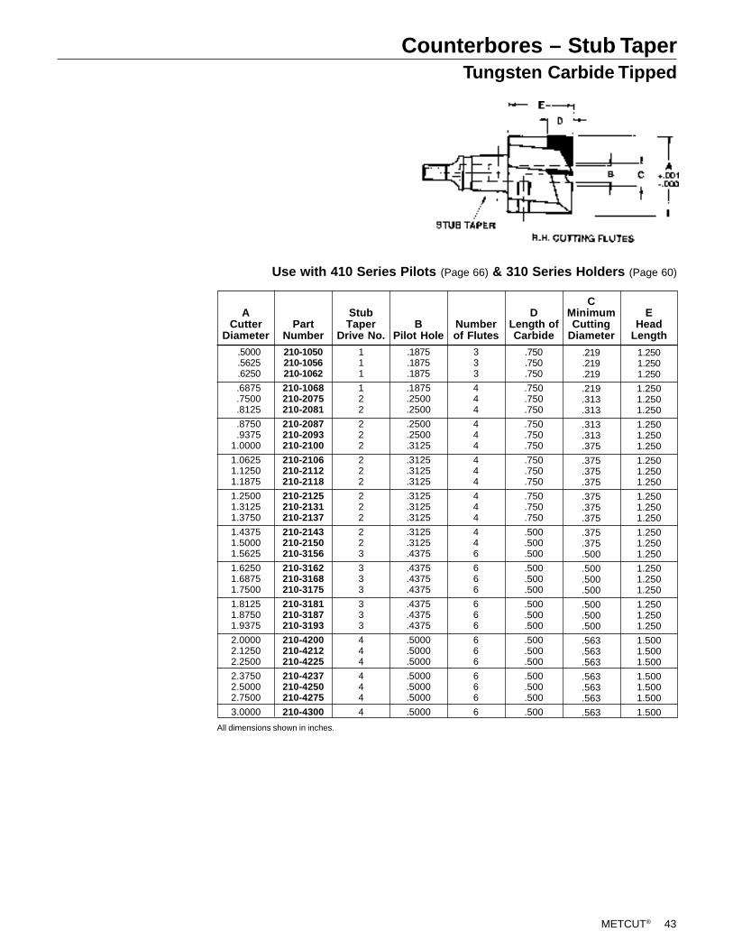
METCUT® 43
Counterbores – Stub TaperTungsten Carbide Tipped
Use with 410 Series Pilots (Page 66) & 310 Series Holders (Page 60)
1.2501.2501.250
1.2501.2501.250
1.2501.2501.250
1.2501.2501.250
1.2501.2501.250
1.2501.2501.250
1.2501.2501.250
1.2501.2501.250
1.5001.5001.500
1.5001.5001.500
1.500
EHead
Length
.219
.219
.219
.219
.313
.313
.313
.313
.375
.375
.375
.375
.375
.375
.375
.375
.375
.500
.500
.500
.500
.500
.500
.500
.563
.563
.563
.563
.563
.563
.563
CMinimumCutting
Diameter
.750
.750
.750
.750
.750
.750
.750
.750
.750
.750
.750
.750
.750
.750
.750
.500
.500
.500
.500
.500
.500
.500
.500
.500
.500
.500
.500
.500
.500
.500
.500
DLength ofCarbide
Numberof Flutes
333
444
444
444
444
446
666
666
666
666
6
BPilot Hole
.1875
.1875
.1875
.1875
.2500
.2500
.2500
.2500
.3125
.3125
.3125
.3125
.3125
.3125
.3125
.3125
.3125
.4375
.4375
.4375
.4375
.4375
.4375
.4375
.5000
.5000
.5000
.5000
.5000
.5000
.5000
111
122
222
222
222
223
333
333
444
444
4
StubTaper
Drive No.
210-1050210-1056210-1062
210-1068210-2075210-2081
210-2087210-2093210-2100
210-2106210-2112210-2118
210-2125210-2131210-2137
210-2143210-2150210-3156
210-3162210-3168210-3175
210-3181210-3187210-3193
210-4200210-4212210-4225
210-4237210-4250210-4275
210-4300
PartNumber
ACutter
Diameter
All dimensions shown in inches.
.5000
.5625
.6250
.6875
.7500
.8125
.8750
.93751.0000
1.06251.12501.1875
1.25001.31251.3750
1.43751.50001.5625
1.62501.68751.7500
1.81251.87501.9375
2.00002.12502.2500
2.37502.50002.7500
3.0000
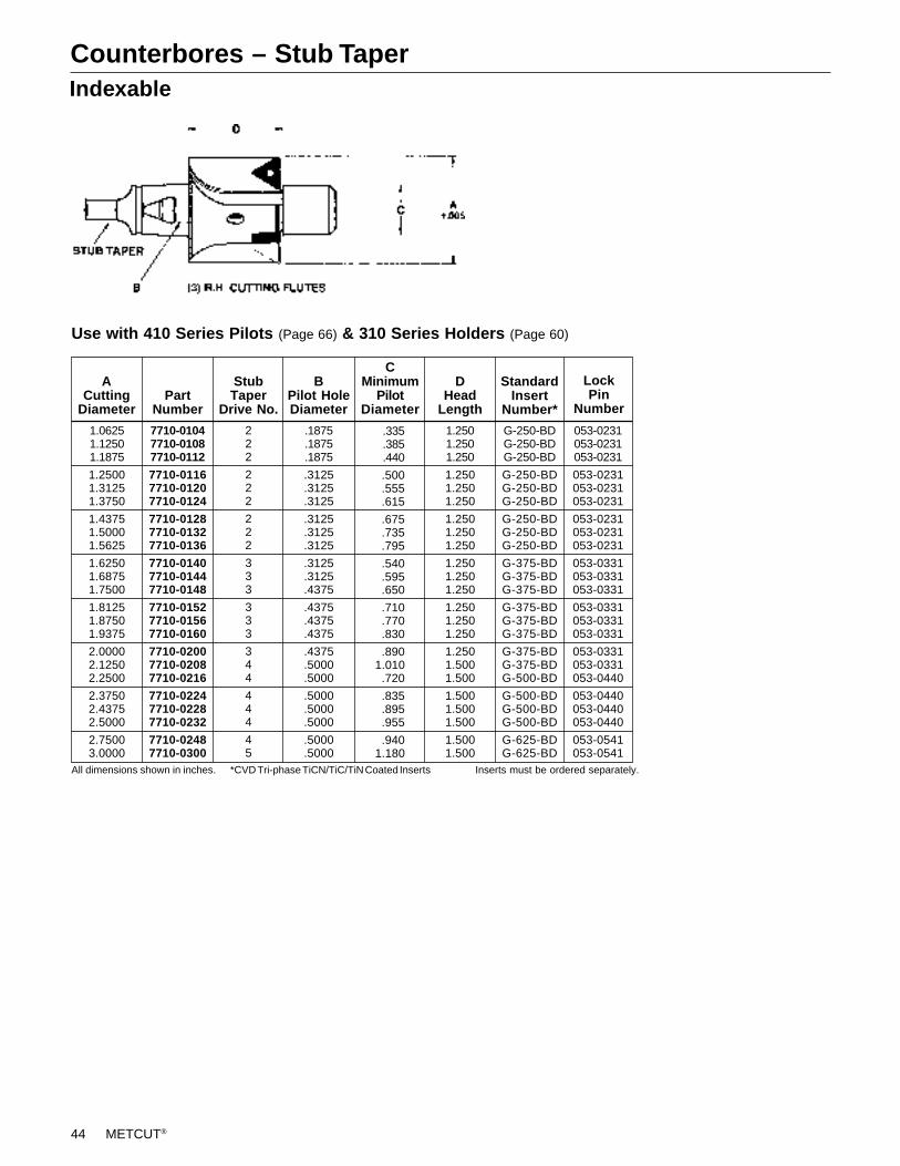
44 METCUT®
Counterbores – Stub TaperIndexable
Use with 410 Series Pilots (Page 66) & 310 Series Holders (Page 60)
All dimensions shown in inches. *CVD Tri-phase TiCN/TiC/TiN Coated Inserts Inserts must be ordered separately.
G-250-BDG-250-BDG-250-BD
G-250-BDG-250-BDG-250-BD
G-250-BDG-250-BDG-250-BD
G-375-BDG-375-BDG-375-BD
G-375-BDG-375-BDG-375-BD
G-375-BDG-375-BDG-500-BD
G-500-BDG-500-BDG-500-BD
G-625-BDG-625-BD
StandardInsert
Number*
053-0231053-0231053-0231
053-0231053-0231053-0231
053-0231053-0231053-0231
053-0331053-0331053-0331
053-0331053-0331053-0331
053-0331053-0331053-0440
053-0440053-0440053-0440
053-0541053-0541
1.06251.12501.1875
1.25001.31251.3750
1.43751.50001.5625
1.62501.68751.7500
1.81251.87501.9375
2.00002.12502.2500
2.37502.43752.5000
2.75003.0000
ACutting
Diameter
7710-01047710-01087710-0112
7710-01167710-01207710-0124
7710-01287710-01327710-0136
7710-01407710-01447710-0148
7710-01527710-01567710-0160
7710-02007710-02087710-0216
7710-02247710-02287710-0232
7710-02487710-0300
PartNumber
222
222
222
333
333
344
444
45
StubTaper
Drive No.
.1875
.1875
.1875
.3125
.3125
.3125
.3125
.3125
.3125
.3125
.3125
.4375
.4375
.4375
.4375
.4375
.5000
.5000
.5000
.5000
.5000
.5000
.5000
BPilot HoleDiameter
1.2501.2501.250
1.2501.2501.250
1.2501.2501.250
1.2501.2501.250
1.2501.2501.250
1.2501.5001.500
1.5001.5001.500
1.5001.500
DHead
Length
LockPin
Number
CMinimum
PilotDiameter
.335
.385
.440
.500
.555
.615
.675
.735
.795
.540
.595
.650
.710
.770
.830
.8901.010.720
.835
.895
.955
.9401.180
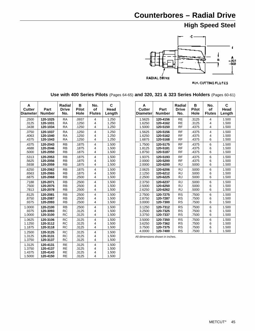
METCUT® 45
Counterbores – Radial DriveHigh Speed Steel
Use with 400 Series Pilots (Pages 64-65) and 320, 321 & 323 Series Holders (Pages 60-61)
ACutter
DiameterPart
Number
RARARA
RARARA
RBRBRB
RBRBRB
RBRBRB
RBRBRB
RBRBRB
RBRCRC
RCRCRC
RCRCRC
RERERERE
RadialDriveNo.
.0937
.1250
.1250
.1250
.1250
.1250
.1875
.1875
.1875
.1875
.1875
.1875
.1875
.1875
.2500
.2500
.2500
.2500
.2500
.2500
.2500
.2500
.3125
.3125
.3125
.3125
.3125
.3125
.3125
.3125
.3125
.3125
.3125
.3125
BPilotHole
120-1025120-1031120-1034
120-1037120-1040120-1043
120-2043120-2046120-2050
120-2053120-2056120-2059
120-2062120-2065120-2068
120-2071120-2075120-2078
120-2081120-2087120-2093
120-2100120-3093120-3100
120-3106120-3112120-3118
120-3125120-3131120-3137
120-4131120-4137120-4143120-4150
.2500
.3125
.3438
.3750
.4063
.4375
.4375
.4688
.5000
.5313
.5625
.5938
.6250
.6563
.6875
.7188
.7500
.7813
.8125
.8750
.9375
1.0000.9375
1.0000
1.06251.12501.1875
1.25001.31251.3750
1.31251.37501.43751.5000
No.of
Flutes
444
444
444
444
444
444
444
444
444
444
4444
1.2501.2501.250
1.2501.2501.250
1.5001.5001.500
1.5001.5001.500
1.5001.5001.500
1.5001.5001.500
1.5001.5001.500
1.5001.5001.500
1.5001.5001.500
1.5001.5001.500
1.5001.5001.5001.500
CHead
Length
ACutter
DiameterPart
Number
RERERF
RFRFRF
RFRFRF
RFRFRJ
RJRJRJ
RJRJRJ
RSRSRS
RSRSRS
RSRSRSRS
RadialDriveNo.
.3125
.3125
.4375
.4375
.4375
.4375
.4375
.4375
.4375
.4375
.4375
.5000
.5000
.5000
.5000
.5000
.5000
.5000
.7500
.7500
.7500
.7500
.7500
.7500
.7500
.7500
.7500
.7500
BPilotHole
120-4156120-4162120-5150
120-5156120-5162120-5168
120-5175120-5181120-5187
120-5193120-5200120-6200
120-6206120-6212120-6225
120-6237120-6250120-6262
120-7275120-7287120-7300
120-7312120-7325120-7337
120-7350120-7362120-7375120-7400
All dimensions shown in inches.
No.of
Flutes
444
446
666
666
666
666
666
666
6666
1.5001.5001.500
1.5001.5001.500
1.5001.5001.500
1.5001.5001.500
1.5001.5001.500
1.5001.5001.500
1.5001.5001.500
1.5001.5001.500
1.5001.5001.5001.500
CHead
Length
1.56251.62501.5000
1.56251.62501.6875
1.75001.81251.8750
1.93752.00002.0000
2.06252.12502.2500
2.37502.50002.6250
2.75002.87503.0000
3.12503.25003.3750
3.50003.62503.75004.0000
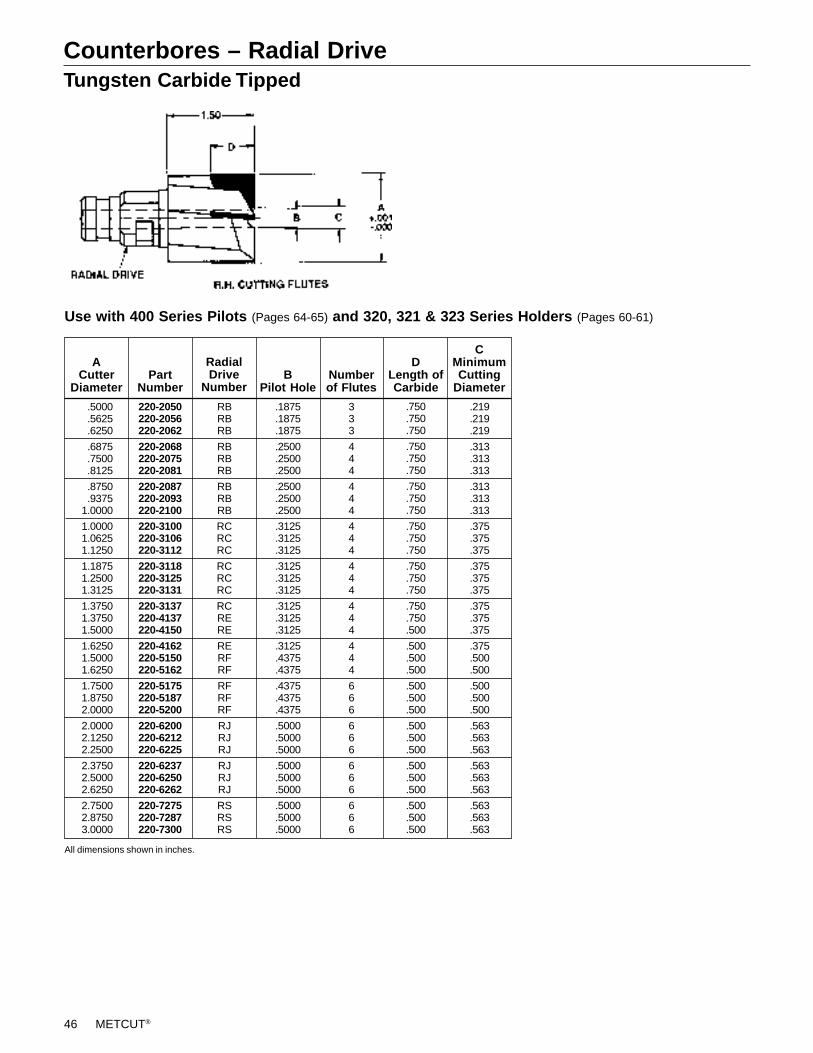
46 METCUT®
Counterbores – Radial DriveTungsten Carbide Tipped
Use with 400 Series Pilots (Pages 64-65) and 320, 321 & 323 Series Holders (Pages 60-61)
.219
.219
.219
.313
.313
.313
.313
.313
.313
.375
.375
.375
.375
.375
.375
.375
.375
.375
.375
.500
.500
.500
.500
.500
.563
.563
.563
.563
.563
.563
.563
.563
.563
CMinimumCutting
Diameter
.750
.750
.750
.750
.750
.750
.750
.750
.750
.750
.750
.750
.750
.750
.750
.750
.750
.500
.500
.500
.500
.500
.500
.500
.500
.500
.500
.500
.500
.500
.500
.500
.500
DLength ofCarbide
Numberof Flutes
333
444
444
444
444
444
444
666
666
666
666
BPilot Hole
.1875
.1875
.1875
.2500
.2500
.2500
.2500
.2500
.2500
.3125
.3125
.3125
.3125
.3125
.3125
.3125
.3125
.3125
.3125
.4375
.4375
.4375
.4375
.4375
.5000
.5000
.5000
.5000
.5000
.5000
.5000
.5000
.5000
RBRBRB
RBRBRB
RBRBRB
RCRCRC
RCRCRC
RCRERE
RERFRF
RFRFRF
RJRJRJ
RJRJRJ
RSRSRS
PartNumber
220-2050220-2056220-2062
220-2068220-2075220-2081
220-2087220-2093220-2100220-3100220-3106220-3112
220-3118220-3125220-3131
220-3137220-4137220-4150
220-4162220-5150220-5162
220-5175220-5187220-5200
220-6200220-6212220-6225
220-6237220-6250220-6262
220-7275220-7287220-7300
ACutter
Diameter
RadialDrive
Number
All dimensions shown in inches.
.5000
.5625
.6250
.6875
.7500
.8125
.8750
.93751.0000
1.00001.06251.1250
1.18751.25001.3125
1.37501.37501.5000
1.62501.50001.6250
1.75001.87502.0000
2.00002.12502.2500
2.37502.50002.6250
2.75002.87503.0000
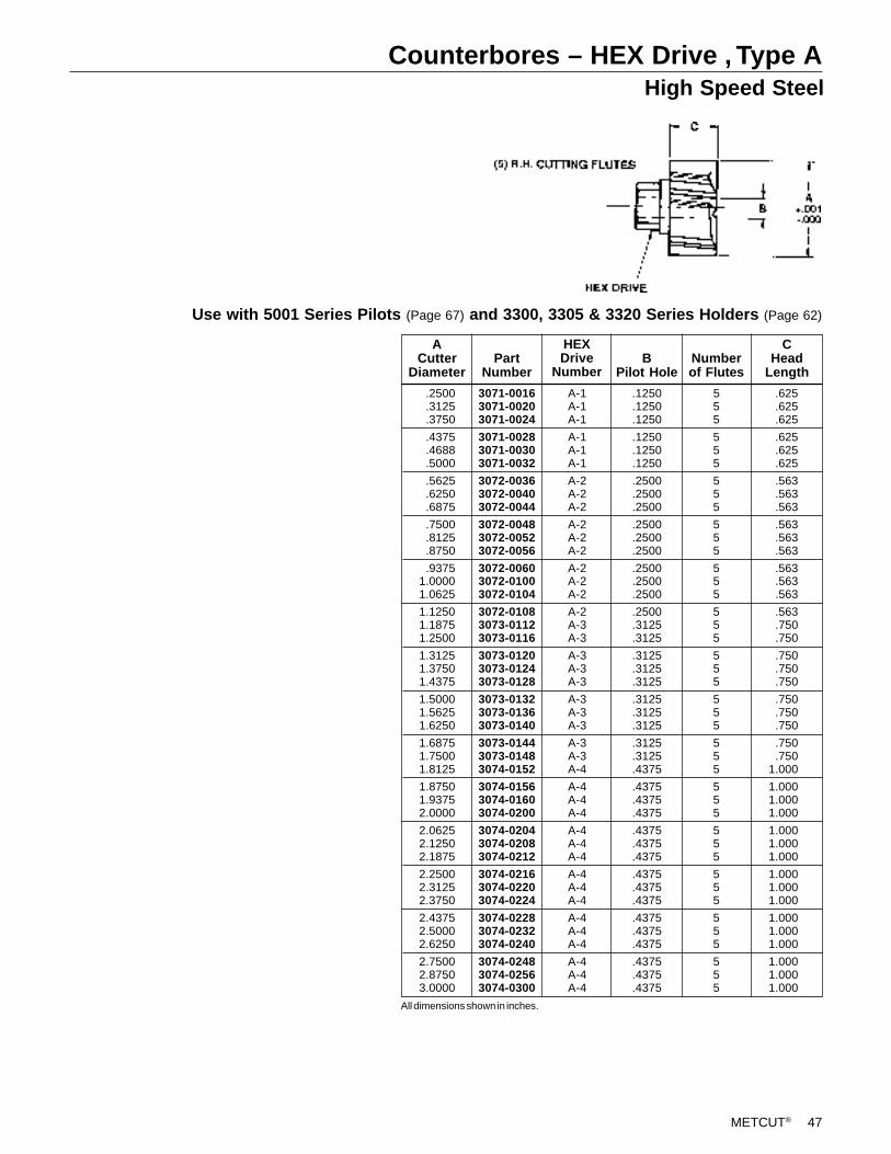
METCUT® 47
Counterbores – HEX Drive , Type AHigh Speed Steel
Use with 5001 Series Pilots (Page 67) and 3300, 3305 & 3320 Series Holders (Page 62)
CHead
LengthNumberof Flutes
555
555
555
555
555
555
555
555
555
555
555
555
555
555
BPilot Hole
.1250
.1250
.1250
.1250
.1250
.1250
.2500
.2500
.2500
.2500
.2500
.2500
.2500
.2500
.2500
.2500
.3125
.3125
.3125
.3125
.3125
.3125
.3125
.3125
.3125
.3125
.4375
.4375
.4375
.4375
.4375
.4375
.4375
.4375
.4375
.4375
.4375
.4375
.4375
.4375
.4375
.4375
A-1A-1A-1
A-1A-1A-1
A-2A-2A-2
A-2A-2A-2
A-2A-2A-2
A-2A-3A-3
A-3A-3A-3
A-3A-3A-3
A-3A-3A-4
A-4A-4A-4
A-4A-4A-4
A-4A-4A-4
A-4A-4A-4
A-4A-4A-4
PartNumber
3071-00163071-00203071-0024
3071-00283071-00303071-0032
3072-00363072-00403072-0044
3072-00483072-00523072-0056
3072-00603072-01003072-0104
3072-01083073-01123073-0116
3073-01203073-01243073-0128
3073-01323073-01363073-0140
3073-01443073-01483074-0152
3074-01563074-01603074-0200
3074-02043074-02083074-0212
3074-02163074-02203074-0224
3074-02283074-02323074-0240
3074-02483074-02563074-0300
ACutter
Diameter
HEXDrive
Number
.2500
.3125
.3750
.4375
.4688
.5000
.5625
.6250
.6875
.7500
.8125
.8750
.93751.00001.0625
1.12501.18751.2500
1.31251.37501.4375
1.50001.56251.6250
1.68751.75001.8125
1.87501.93752.0000
2.06252.12502.1875
2.25002.31252.3750
2.43752.50002.6250
2.75002.87503.0000
.625
.625
.625
.625
.625
.625
.563
.563
.563
.563
.563
.563
.563
.563
.563
.563
.750
.750
.750
.750
.750
.750
.750
.750
.750
.7501.000
1.0001.0001.000
1.0001.0001.000
1.0001.0001.000
1.0001.0001.000
1.0001.0001.000
All dimensions shown in inches.
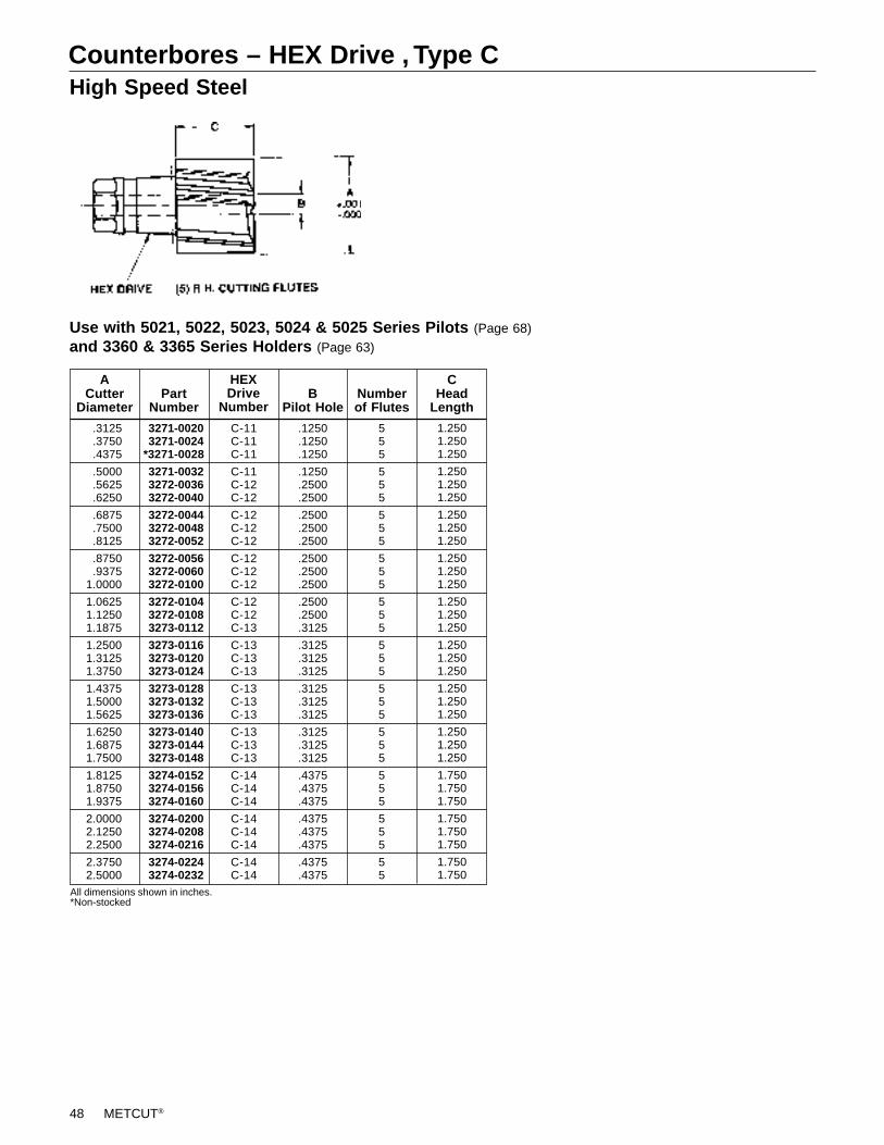
48 METCUT®
Counterbores – HEX Drive , Type CHigh Speed Steel
Use with 5021, 5022, 5023, 5024 & 5025 Series Pilots (Page 68)
and 3360 & 3365 Series Holders (Page 63)
1.2501.2501.250
1.2501.2501.250
1.2501.2501.250
1.2501.2501.250
1.2501.2501.250
1.2501.2501.250
1.2501.2501.250
1.2501.2501.250
1.7501.7501.750
1.7501.7501.750
1.7501.750
CHead
LengthNumberof Flutes
555
555
555
555
555
555
555
555
555
555
55
BPilot Hole
.1250
.1250
.1250
.1250
.2500
.2500
.2500
.2500
.2500
.2500
.2500
.2500
.2500
.2500
.3125
.3125
.3125
.3125
.3125
.3125
.3125
.3125
.3125
.3125
.4375
.4375
.4375
.4375
.4375
.4375
.4375
.4375
C-11C-11C-11
C-11C-12C-12
C-12C-12C-12
C-12C-12C-12
C-12C-12C-13
C-13C-13C-13
C-13C-13C-13
C-13C-13C-13
C-14C-14C-14
C-14C-14C-14
C-14C-14
PartNumber
3271-0020 3271-0024*3271-0028
3271-0032 3272-0036 3272-0040
3272-0044 3272-0048 3272-0052
3272-0056 3272-0060 3272-0100
3272-0104 3272-0108 3273-0112
3273-0116 3273-0120 3273-0124
3273-0128 3273-0132 3273-0136
3273-0140 3273-0144 3273-0148
3274-0152 3274-0156 3274-0160
3274-0200 3274-0208 3274-0216
3274-0224 3274-0232
ACutter
Diameter
HEXDrive
Number
All dimensions shown in inches.*Non-stocked
.3125
.3750
.4375
.5000
.5625
.6250
.6875
.7500
.8125
.8750
.93751.0000
1.06251.12501.1875
1.25001.31251.3750
1.43751.50001.5625
1.62501.68751.7500
1.81251.87501.9375
2.00002.12502.2500
2.37502.5000
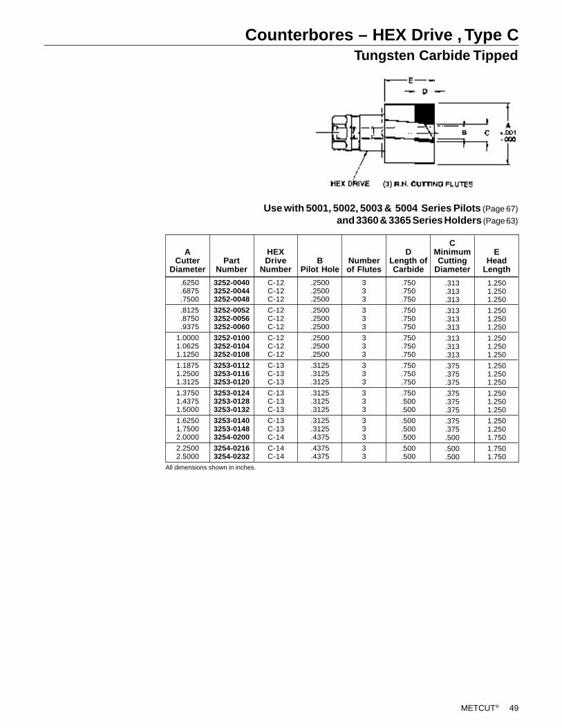
METCUT® 49
Counterbores – HEX Drive , Type CTungsten Carbide Tipped
Use with 5001, 5002, 5003 & 5004 Series Pilots (Page 67)
and 3360 & 3365 Series Holders (Page 63)
1.2501.2501.250
1.2501.2501.250
1.2501.2501.250
1.2501.2501.250
1.2501.2501.250
1.2501.2501.750
1.7501.750
EHead
Length
.313
.313
.313
.313
.313
.313
.313
.313
.313
.375
.375
.375
.375
.375
.375
.375
.375
.500
.500
.500
CMinimumCutting
Diameter
.750
.750
.750
.750
.750
.750
.750
.750
.750
.750
.750
.750
.750
.500
.500
.500
.500
.500
.500
.500
DLength ofCarbide
Numberof Flutes
333
333
333
333
333
333
33
BPilot Hole
.2500
.2500
.2500
.2500
.2500
.2500
.2500
.2500
.2500
.3125
.3125
.3125
.3125
.3125
.3125
.3125
.3125
.4375
.4375
.4375
C-12C-12C-12
C-12C-12C-12
C-12C-12C-12
C-13C-13C-13
C-13C-13C-13
C-13C-13C-14
C-14C-14
3252-00403252-00443252-0048
3252-00523252-00563252-0060
3252-01003252-01043252-0108
3253-01123253-01163253-0120
3253-01243253-01283253-0132
3253-01403253-01483254-0200
3254-02163254-0232
PartNumber
ACutter
Diameter
HEXDrive
Number
All dimensions shown in inches.
.6250
.6875
.7500
.8125
.8750
.9375
1.00001.06251.1250
1.18751.25001.3125
1.37501.43751.5000
1.62501.75002.0000
2.25002.5000
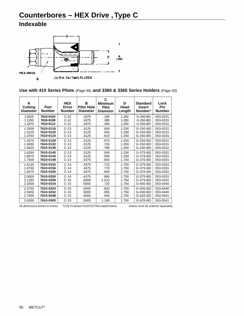
50 METCUT®
Counterbores – HEX Drive , Type CIndexable
Use with 410 Series Pilots (Page 66) and 3360 & 3365 Series Holders (Page 63)
All dimensions shown in inches. *CVD Tri-phase TiCN/TiC/TiN Coated Inserts Inserts must be ordered separately.
.1875
.1875
.1875
.3125
.3125
.3125
.3125
.3125
.3125
.3125
.3125
.4375
.4375
.4375
.4375
.4375
.5000
.5000
.5000
.5000
.5000
.5000
BPilot HoleDiameter
G-250-BDG-250-BDG-250-BD
G-250-BDG-250-BDG-250-BD
G-250-BDG-250-BDG-250-BD
G-375-BDG-375-BDG-375-BD
G-375-BDG-375-BDG-375-BD
G-375-BDG-375-BDG-500-BD
G-500-BDG-500-BDG-625-BD
G-625-BD
StandardInsert
Number*
053-0231053-0231053-0231
053-0231053-0231053-0231
053-0231053-0231053-0231
053-0331053-0331053-0331
053-0331053-0331053-0331
053-0331053-0331053-0440
053-0440053-0440053-0541
053-0541
1.06251.12501.1875
1.25001.31251.3750
1.43751.50001.5625
1.62501.68751.7500
1.81251.87501.9375
2.00002.12502.2500
2.37502.50002.7500
3.0000
ACutting
Diameter
7610-01047610-01087610-0112
7610-01167610-01207610-0124
7610-01287610-01327610-0136
7610-01407610-01447610-0148
7610-01527610-01567610-0160
7610-02007610-02087610-0216
7610-02247610-02327610-0248
7610-0300
PartNumber
C-12C-12C-12
C-13C-13C-13
C-13C-13C-13
C-13C-13C-14
C-14C-14C-14
C-14C-15C-15
C-15C-15C-15
C-15
HEXDrive
Number
1.2501.2501.250
1.2501.2501.250
1.2501.2501.250
1.2501.2501.750
1.7501.7501.750
1.7501.7501.750
1.7501.7501.750
1.750
DHead
Length
LockPin
Number
CMinimum
PilotDiameter
.335
.385
.440
.500
.555
.615
.675
.735
.795
.540
.595
.650
.710
.770
.830
.8901.010.720
.835
.955
.940
1.180
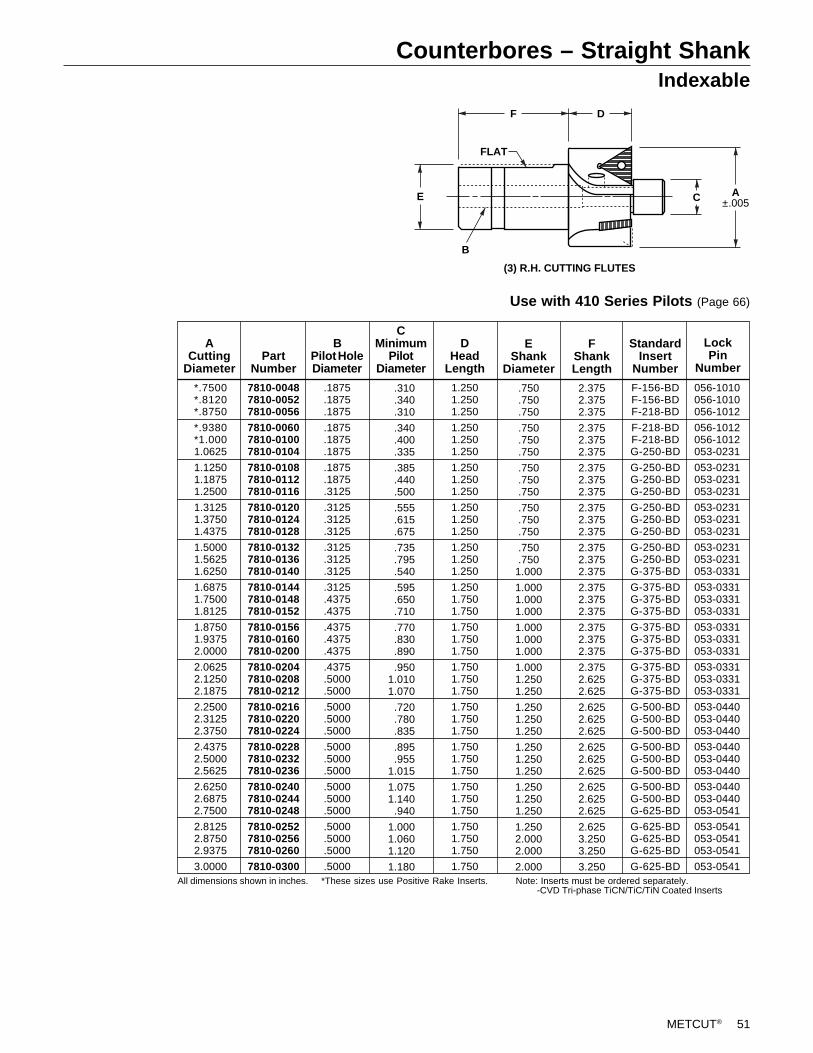
METCUT® 51
Counterbores – Straight ShankIndexable
Use with 410 Series Pilots (Page 66)
DF
FLAT
E C A±.005
(3) R.H. CUTTING FLUTES
B
All dimensions shown in inches. *These sizes use Positive Rake Inserts. Note: Inserts must be ordered separately. -CVD Tri-phase TiCN/TiC/TiN Coated Inserts
*.7500*.8120*.8750
*.9380*1.0001.0625
1.12501.18751.2500
1.31251.37501.4375
1.50001.56251.6250
1.68751.75001.8125
1.87501.93752.0000
2.06252.12502.1875
2.25002.31252.3750
2.43752.50002.5625
2.62502.68752.7500
2.81252.87502.9375
3.0000
ACutting
Diameter
7810-00487810-00527810-0056
7810-00607810-01007810-0104
7810-01087810-01127810-0116
7810-01207810-01247810-0128
7810-01327810-01367810-0140
7810-01447810-01487810-0152
7810-01567810-01607810-0200
7810-02047810-02087810-0212
7810-02167810-02207810-0224
7810-02287810-02327810-0236
7810-02407810-02447810-0248
7810-02527810-02567810-0260
7810-0300
PartNumber
.1875
.1875
.1875
.1875
.1875
.1875
.1875
.1875
.3125
.3125
.3125
.3125
.3125
.3125
.3125
.3125
.4375
.4375
.4375
.4375
.4375
.4375
.5000
.5000
.5000
.5000
.5000
.5000
.5000
.5000
.5000
.5000
.5000
.5000
.5000
.5000
.5000
BPilot HoleDiameter
1.2501.2501.250
1.2501.2501.250
1.2501.2501.250
1.2501.2501.250
1.2501.2501.250
1.2501.7501.750
1.7501.7501.750
1.7501.7501.750
1.7501.7501.750
1.7501.7501.750
1.7501.7501.750
1.7501.7501.750
1.750
DHead
Length
CMinimum
PilotDiameter
.310
.340
.310
.340
.400
.335
.385
.440
.500
.555
.615
.675
.735
.795
.540
.595
.650
.710
.770
.830
.890
.9501.0101.070
.720
.780
.835
.895
.9551.015
1.0751.140
.940
1.0001.0601.120
1.180
F-156-BDF-156-BDF-218-BD
F-218-BDF-218-BDG-250-BD
G-250-BDG-250-BDG-250-BD
G-250-BDG-250-BDG-250-BD
G-250-BDG-250-BDG-375-BD
G-375-BDG-375-BDG-375-BD
G-375-BDG-375-BDG-375-BD
G-375-BDG-375-BDG-375-BD
G-500-BDG-500-BDG-500-BD
G-500-BDG-500-BDG-500-BD
G-500-BDG-500-BDG-625-BD
G-625-BDG-625-BDG-625-BD
G-625-BD
StandardInsert
Number
056-1010056-1010056-1012
056-1012056-1012053-0231
053-0231053-0231053-0231
053-0231053-0231053-0231
053-0231053-0231053-0331
053-0331053-0331053-0331
053-0331053-0331053-0331
053-0331053-0331053-0331
053-0440053-0440053-0440
053-0440053-0440053-0440
053-0440053-0440053-0541
053-0541053-0541053-0541
053-0541
LockPin
Number
.750
.750
.750
.750
.750
.750
.750
.750
.750
.750
.750
.750
.750
.7501.000
1.0001.0001.000
1.0001.0001.000
1.0001.2501.250
1.2501.2501.250
1.2501.2501.250
1.2501.2501.250
1.2502.0002.000
2.000
EShank
Diameter
2.3752.3752.375
2.3752.3752.375
2.3752.3752.375
2.3752.3752.375
2.3752.3752.375
2.3752.3752.375
2.3752.3752.375
2.3752.6252.625
2.6252.6252.625
2.6252.6252.625
2.6252.6252.625
2.6253.2503.250
3.250
FShankLength
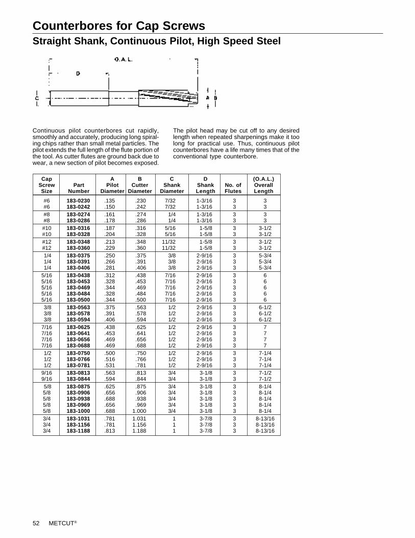
52 METCUT®
Counterbores for Cap ScrewsStraight Shank, Continuous Pilot, High Speed Steel
Continuous pilot counterbores cut rapidly,smoothly and accurately, producing long spiral-ing chips rather than small metal particles. Thepilot extends the full length of the flute portion ofthe tool. As cutter flutes are ground back due towear, a new section of pilot becomes exposed.
The pilot head may be cut off to any desiredlength when repeated sharpenings make it toolong for practical use. Thus, continuous pilotcounterbores have a life many times that of theconventional type counterbore.
#6 183-0230 .135 .230 7/32 1-3/16 3 3#6 183-0242 .150 .242 7/32 1-3/16 3 3#8 183-0274 .161 .274 1/4 1-3/16 3 3#8 183-0286 .178 .286 1/4 1-3/16 3 3#10 183-0316 .187 .316 5/16 1-5/8 3 3-1/2#10 183-0328 .204 .328 5/16 1-5/8 3 3-1/2#12 183-0348 .213 .348 11/32 1-5/8 3 3-1/2#12 183-0360 .229 .360 11/32 1-5/8 3 3-1/2 1/4 183-0375 .250 .375 3/8 2-9/16 3 5-3/4 1/4 183-0391 .266 .391 3/8 2-9/16 3 5-3/4 1/4 183-0406 .281 .406 3/8 2-9/16 3 5-3/45/16 183-0438 .312 .438 7/16 2-9/16 3 65/16 183-0453 .328 .453 7/16 2-9/16 3 65/16 183-0469 .344 .469 7/16 2-9/16 3 65/16 183-0484 .328 .484 7/16 2-9/16 3 65/16 183-0500 .344 .500 7/16 2-9/16 3 6 3/8 183-0563 .375 .563 1/2 2-9/16 3 6-1/2 3/8 183-0578 .391 .578 1/2 2-9/16 3 6-1/2 3/8 183-0594 .406 .594 1/2 2-9/16 3 6-1/27/16 183-0625 .438 .625 1/2 2-9/16 3 77/16 183-0641 .453 .641 1/2 2-9/16 3 77/16 183-0656 .469 .656 1/2 2-9/16 3 77/16 183-0688 .469 .688 1/2 2-9/16 3 7 1/2 183-0750 .500 .750 1/2 2-9/16 3 7-1/4 1/2 183-0766 .516 .766 1/2 2-9/16 3 7-1/4 1/2 183-0781 .531 .781 1/2 2-9/16 3 7-1/49/16 183-0813 .563 .813 3/4 3-1/8 3 7-1/29/16 183-0844 .594 .844 3/4 3-1/8 3 7-1/2 5/8 183-0875 .625 .875 3/4 3-1/8 3 8-1/45/8 183-0906 .656 .906 3/4 3-1/8 3 8-1/45/8 183-0938 .688 .938 3/4 3-1/8 3 8-1/45/8 183-0969 .656 .969 3/4 3-1/8 3 8-1/45/8 183-1000 .688 1.000 3/4 3-1/8 3 8-1/43/4 183-1031 .781 1.031 1 3-7/8 3 8-13/163/4 183-1156 .781 1.156 1 3-7/8 3 8-13/163/4 183-1188 .813 1.188 1 3-7/8 3 8-13/16
Cap A B C D (O.A.L.)Screw Part Pilot Cutter Shank Shank No. of OverallSize Number Diameter Diameter Diameter Length Flutes Length
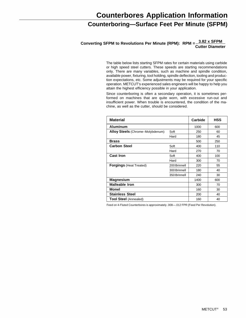
METCUT® 53
Counterbores Application InformationCounterboring—Surface Feet Per Minute (SFPM)
The table below lists starting SFPM rates for certain materials using carbideor high speed steel cutters. These speeds are starting recommendationsonly. There are many variables, such as machine and spindle condition,available power, fixturing, tool holding, spindle deflection, tooling and produc-tion expectations, etc. Some adjustments may be required for your specificoperation. METCUT’s experienced sales engineers will be happy to help youattain the highest efficiency possible in your application.
Since counterboring is often a secondary operation, it is sometimes per-formed on machines that are quite worn, with excessive run-out andinsufficient power. When trouble is encountered, the condition of the ma-chine, as well as the cutter, should be considered.
Converting SFPM to Revolutions Per Minute (RPM): RPM = 3.82 x SFPMCutter Diameter
AluminumAlloy Steels (Chrome–Molybdenum)
BrassCarbon Steel
Cast Iron
Forgings (Heat Treated)
MagnesiumMalleable IronMonelStainless SteelTool Steel (Annealed)
Material
Soft
Hard
Soft
Hard
Soft
Hard
200 Brinnell
300 Brinnell
350 Brinnell
HSSCarbide
1000
250
180
500
400
270
400
300
220
180
240
1400
300
160
200
160
600
60
45
250
110
70
100
70
55
40
30
600
70
30
40
40
Feed on 4-Fluted Counterbores is approximately .008—.012 FPR (Feed Per Revolution).
54 METCUT®
266-6050 60° .500 1.00 2.25 .375 .156 F-2501-BD 1 056-1016 056-2017 T-7266-6075 60° .750 1.00 3.25 .750 .443 F-2501-BD 1 056-1017 056-2017 T-7266-6100 60° 1.000 1.00 3.25 .750 .693 F-2501-BD 2 056-1017 056-2017 T-7266-6125 60° 1.250 1.00 3.50 1.000 .943 F-2501-BD 3 056-1017 056-2017 T-7266-6150 60° 1.500 1.00 3.50 1.000 1.193 F-2501-BD 3 056-1017 056-2017 T-7
266-8054 82° .540 1.00 2.25 .375 .125 F-2501-BD 1 056-1016 056-2017 T-7266-8075 82° .750 1.00 3.25 .750 .347 F-2501-BD 1 056-1017 056-2017 T-7266-8100 82° 1.000 1.00 3.25 .750 .597 F-2501-BD 2 056-1017 056-2017 T-7266-8125 82° 1.250 1.00 3.50 1.000 .847 F-2501-BD 3 056-1017 056-2017 T-7266-8150 82° 1.500 1.00 3.50 1.000 1.097 F-2501-BD 3 056-1017 056-2017 T-7
266-9058 90° .582 1.00 2.25 .375 .125 F-2501-BD 1 056-1017 056-2017 T-7266-9075 90° .750 1.00 3.25 .750 .315 F-2501-BD 1 056-1017 056-2017 T-7266-9100 90° 1.000 1.00 3.25 .750 .565 F-2501-BD 2 056-1017 056-2017 T-7266-9125 90° 1.250 1.00 3.50 1.000 .815 F-2501-BD 3 056-1017 056-2017 T-7266-9150 90° 1.500 1.00 3.50 1.000 1.065 F-2501-BD 3 056-1017 056-2017 T-7
266-1063 100° .630 1.00 2.25 .375 .125 F-2501-BD 1 056-1017 056-2017 T-7
A B C D E Standard Torx TorxPart Included Maximum Extension Overall Shank M inimum Insert Effective Screw Wrench
Number Angle Diameter Length Length Diameter Diameter Number Inserts Part No. Part No.
Countersinks–Indexable – Through CoolantStraight Shank
All dimensions shown in inches.Diameters are measured at the tangency point of the insert cutting edge and corner radii.Inserts must be ordered separately.NOTE: Shank can be ordered with an endmill flat. Call quotations for prices and availability.
Use with 400 Series Pilots (Pages 64-65) and 300, 301 & 303 Series Holders (Pages 58-59)
C
B
1.375PINDRIVE
A
Countersinks – Pin Drive (can be used as a straight shank tool)
High Speed Steel, Piloted
444
444
455
111
122
233
.1875
.1875
.2500
.2500
.3125
.3125
.3125
.4375
.5000
——
*101-6075
*101-6100*101-6112*101-6125
*101-6150*101-6200
—
60° 82° 90°
——
*101-8075
*101-8100*101-8112*101-8125
*101-8150*101-8200
—
101-9050101-9062101-9075
101-9100101-9112101-9125
101-9150101-9200101-9250
PinDrive
All dimensions shown in inches.*Non-stocked.
Numberof Flutes
CSmallEnd
BPilot HoleDiameter
AHead
Diameter
Included Angle & Part No.
.500
.625
.750
1.0001.1251.250
1.5002.0002.500
.313
.313
.375
.375
.563
.563
.625
.8751.250
AEANGLED
C
B
METCUT® 55
Countersinks – Radial DriveHigh Speed Steel, Piloted
Use with 400 Series Pilots (Pages 64-65) and 320, 321 & 323 Series Holders (Pages 60-61)
High Speed Steel, Unpiloted
Use with 320, 321 & 323 Series Holders (Pages 60-61)
AHead
Diameter
.6250
.7500
.8750
1.00001.12501.2500
1.37501.50001.7500
2.00002.5000
All dimensions shown in inches.*Non-stocked.
121-9062121-9075121-9087
121-9100121-9112121-9125
121-9137121-9150121-9175
121-9200121-9250
RBRBRB
RCRCRC
RERERF
RFRJ
.1875
.2500
.2500
.2500
.3125
.3125
.3125
.3125
.4375
.4375
.5000
CPilot Hole
Dia.B
Small EndRadialDrive
444
444
446
66
Numberof
Flutes
.313
.375
.375
.438
.563
.625
.625
.7501.000
1.0001.500
90° IncludedAngle
Part No.
60° IncludedAngle
Part No.
——
*121-6087
*121-6100*121-6112*121-6125
*121-6137*121-6150
—
*121-6200—
82° IncludedAngle
Part No.
——
*121-8087
*121-8100*121-8112*121-8125
*121-8137*121-8150
—
——
AHead
Diameter
All dimensions shown in inches.*Non-stocked.
.5000
.6250
.7500
.87501.00001.1250
1.25001.37501.5000
1.62501.75001.8750
2.00002.25002.5000
122-9050122-9062122-9075
122-9087122-9100122-9112
122-9125122-9137122-9150
122-9162122-9175122-9187
122-9200122-9225122-9250
90° IncludedAngle
Part No.
RBRBRB
RBRCRC
RCRERE
RERFRF
RFRJRJ
333
333
333
355
555
Numberof
FlutesB
Small EndRadialDrive
.188
.188
.188
.188
.188
.313
.375
.500
.625
.6881.0001.000
1.0001.2501.500
——
*122-6075
*122-6087*122-6100*122-6112
*122-6125*122-6137*122-6150
———
———
60° IncludedAngle
Part No.
———
*122-8087*122-8100*122-8112
*122-8125*122-8137*122-8150
*122-8162*122-8175
—
———
82° IncludedAngle
Part No.

56 METCUT®Metal Cutting Tools56
METCUT® 57Metal Cutting Tools 57
58 METCUT®
Countersinks – Three FluteTungsten Carbide Tipped, Straight Shank
Countersinks – Four Flute (Center Reamers)High Speed Steel, Straight Shank
Countersinks – Single FluteHigh Speed Steel
All dimensions shown in inches.
82° 90°
AHead
Diameter
Included Angle & Part No. SShank
Diameter
LShankLength
DOverallLength
.250 177-8025 177-9025 .187 .750 1.500
.375 177-8037 177-9037 .250 .875 1.750
.500 177-8050 177-9050 .375 1.000 2.000
.625 177-8062 177-9062 .375 1.000 2.250
.750 177-8075 — .500 1.250 2.625
All dimensions shown in inches.*Non-stocked.
82° 90°
166-9037166-9050
166-9062166-9075166-9100
166-9125166-9150
1.001.00
1.001.501.50
1.501.50
AHead
Diameter
Included Angle & Part No. SShank
Diameter
LShankLength
.375
.500
.625
.7501.000
1.2501.500
.250
.250
.250
.500
.500
.500
.500
1.621.75
1.692.562.50
2.883.12
DOverallLength
166-8037 166-8050
166-8062 166-8075 166-8100
*166-8125*166-8150
A Minimum S L D Head Cutting Shank Shank Overall
Diameter 82° Diameter Diameter Length Length
.375 179-8037 .109 .250 .875 1.656
.500 179-8050 .141 .250 1.000 1.844
.750 179-8075 .188 .500 1.250 2.4061.000 179-8100 .250 .500 1.500 2.813
Included Angle & Part No.
METCUT® 59
Holders for Counterbores & Countersinks
Pin Drive Holders with Straight Shank
Pin Drive Holders with Taper Shank
Use with 100, 101, 102 & 200 Series Cutters (Pages 40-41, 54)
Use with 100, 101, 102 & 200 Series Cutters (Pages 40-41, 54)
C
B
A
PIN DRIVEMORSE TAPER
+.000Ð.001
D
B
A
PIN DRIVESTRAIGHT SHANK
C
+.000Ð.001
All dimensions shown in inches.
2.2502.2503.000
3.0003.0003.250
3.0003.0003.313
3.0003.0003.5003.000
BHead
Length
121
232
343
4545
PinDrive
001
112
223
3344
MorseTaper
ABody
Diameter
All dimensions shown in inches.
.3125 to .4375
.3125 to .4375.4375 to 1.1250
.4375 to 1.1250
.4375 to 1.12501.0625 to 1.7500
1.0625 to 1.75001.0625 to 1.75001.6875 to 3.1250
1.6875 to 3.12501.6875 to 3.12503.0000 to 4.00003.0000 to 4.0000
300-0107300-0207300-1110
300-1210300-1310300-2215
300-2315300-2415300-3320
300-3420300-3520300-4430300-4530
PartNumberCutter Range
.7500
.75001.0625
1.06251.06251.5000
1.50001.50002.0000
2.00002.00003.00003.0000
CProjection
2.3752.4373.375
3.1873.1873.437
3.1873.2503.500
3.2503.2503.7503.250
5.2506.0006.000
7.0007.0007.000
7.0007.0007.500
COverallLength
2.2503.0003.000
3.0003.0003.000
3.0003.0003.000
PinDrive
011
223
334
BHead
Length
ABody
Diameter
DShank
DiameterCutter Range
303-0007303-1010303-1110
303-2115303-2215303-3220
303-3320303-3423303-4530
PartNumber
.2500 to .4375.4375 to 1.1250.4375 to 1.1250
1.0625 to 1.75001.0625 to 1.75001.6875 to 3.1250
1.6875 to 3.12501.6875 to 3.12503.0000 to 4.0000
.500
.500
.750
.7501.0001.000
1.2501.5002.000
.75001.06251.0625
1.50001.50002.0000
2.00002.37503.0000
60 METCUT®
Holders for Counterbores & CountersinksStub Taper with Taper Shank
Use with 110, 210 & 7710 Series Cutters (Pages 42-44, 55)
Radial Drive with Straight Shank
Use with 120, 121, 122 & 220 Series Cutters (Pages 45-46, 55)
223
423
434
55
122
233
344
45
1.7502.1882.188
2.1882.5632.563
2.5633.0003.000
3.0003.750
1.9382.3752.375
2.4382.7502.750
2.8133.1883.250
3.2504.000
All dimensions shown in inches.
.4375 to .6875.7500 to 1.5625.7500 to 1.5625
.7500 to 1.56251.5625 to 2.06251.5625 to 2.0625
1.5625 to 2.06252.0000 to 3.00002.0000 to 3.0000
2.0000 to 3.00002.8750 to 3.0000
310-1208310-2211310-2311
310-2411310-3214310-3314
310-3414310-4318310-4418
310-4518310-5527
ABody
DiameterMorseTaper
StubTaper
PartNumberCutter Range
BBody
LengthC
Projection
.87501.18751.1875
1.18751.43751.4375
1.43751.87501.8750
1.87502.7500
RARBRC
RCRERF
RFRJRS
2.2503.0003.000
3.0003.0003.000
3.0003.0003.000
5.256.006.00
7.007.007.00
7.507.507.50
.2500 to .4375.4375 to 1.0000.9375 to 1.1250
.9375 to 1.37501.3125 to 1.62501.5000 to 2.0000
1.5000 to 2.00002.0000 to 2.68752.7500 to 4.5000
323-1107323-2210323-3310
323-3410323-4415323-5515
323-5615323-6620323-7727
BBody
LengthRadialDrive
PartNumberCutter Range
CShank
Dia.
ABodyDia.
All dimensions shown in inches.
DOverallLength
.75001.06251.0625
1.06251.50001.5000
1.50002.00002.7500
.5000
.6250
.7500
1.00001.00001.2500
1.50001.50002.0000
METCUT® 61
Holders for Counterbores & CountersinksRadial Drive with Morse Taper Shank
Radial Drive with Acme Threaded Shank
Use with 120, 121, 122, 160, 186, 220 & 260 Series Cutters (Pages 45-46, 55, 77, 79, 83, 87)
Use with 120, 121, 122,160, 186, 220 & 260 Series Cutters (Pages 45-46, 55, 77, 79, 83, 87)
121
223
343
434
545
RARARB
RBRCRC
RERERF
RFRJRJ
RJRSRS
2.2502.2503.000
3.0003.0003.000
3.0003.0003.000
3.0003.0003.000
3.0003.0003.000
2.3752.4383.125
3.1883.1883.188
3.1883.2503.188
3.2503.1883.250
3.2503.2503.250
RadialDrive
MorseTaper
All dimensions shown in inches.
CProjection
BBody
Length
ABody
DiameterCutter Range
.2500 to .4375
.2500 to .4375.4375 to 1.0000
.4375 to 1.0000
.9375 to 1.3750
.9375 to 1.3750
1.3125 to 1.62501.3125 to 1.62501.5000 to 2.0000
1.5000 to 2.00002.0000 to 2.62502.0000 to 2.6250
2.0000 to 2.62502.7500 to 4.50002.7500 to 4.5000
PartNumber
320-1107320-1207320-2108
320-2208320-3210320-3310
320-4313320-4413320-5315
320-5415320-6320320-6420
320-6520320-7427320-7527
.7500
.75001.0625
1.06251.06251.0625
1.50001.50001.5000
1.50002.00002.0000
2.00002.75002.7500
All dimensions shown in inches.
A B CCutter Part Radial Acme Body Body OverallRange Number Drive Shank Diameter Length Length
.4375 to 1.0000 321-2109 RB 5/8–16 .9375 3.000 6.000
.4375 to 1.0000 321-2309 RB 7/8–12 .9375 3.000 6.630
.9375 to 1.3750 321-3310 RC 7/8–12 1.0625 3.000 6.630
.9375 to 1.3750 321-3510 RC 1-1/16–12 1.0625 3.000 6.630
.9375 to 1.3750 321-3610 RC 1-3/8–12 1.0625 3.000 7.630
1.3125 to 1.6250 321-4313 RE 7/8–12 1.3750 3.000 6.6301.3125 to 1.6250 321-4513 RE 1-1/16–12 1.3750 3.000 6.630
1.5000 to 2.0000 321-5615 RF 1-3/8–12 1.5000 3.000 7.630
62 METCUT®
Holders for Counterbores & CountersinksHEX Drive , Type A, Straight Shank
HEX Drive , Type A, Taper Shank
Use with 3071, 3072, 3073 & 3074 Series Cutters (Page 47)
Use with 3071, 3072, 3073 & 3074 Series Cutters (Page 47)
A-1A-2A-3
A-4
3.4384.7505.375
6.438All dimensions shown in inches.
.2500 to .5000.5625 to 1.12501.1875 to 1.7500
1.8125 to 3.0000
Cutter Range
3305-90013305-90023305-9003
3305-9004
HEXDrive
PartNumber
DOverallLength
ABody
Diameter
1.4382.2502.375
2.688
BBody
Length
CShank
Diameter
.6250
.87501.2500
1.8750
.375
.500.750
1.000
HEXDrive
123
234
345
A-1A-2A-2
A-3A-3A-3
A-4A-4A-4
MorseTaper
1.3752.1252.250
3.1252.1882.375
3.6882.4382.688
1.5002.3132.438
3.3132.3752.625
3.8752.6882.938
All dimensions shown in inches.
.2500 to .5000.5625 to 1.1250.5625 to 1.1250
1.1875 to 1.75001.1875 to 1.75001.1875 to 1.7500
1.8125 to 3.00001.8125 to 3.00001.8125 to 3.0000
Cutter Range
3300-90013300-90023320-9023
3320-90323300-90033320-9034
3320-90433300-90043320-9045
PartNumber
ABody
Diameter
BBody
LengthD
Projection
.6250
.8750
.8750
1.25001.25001.2500
1.87501.87501.8750
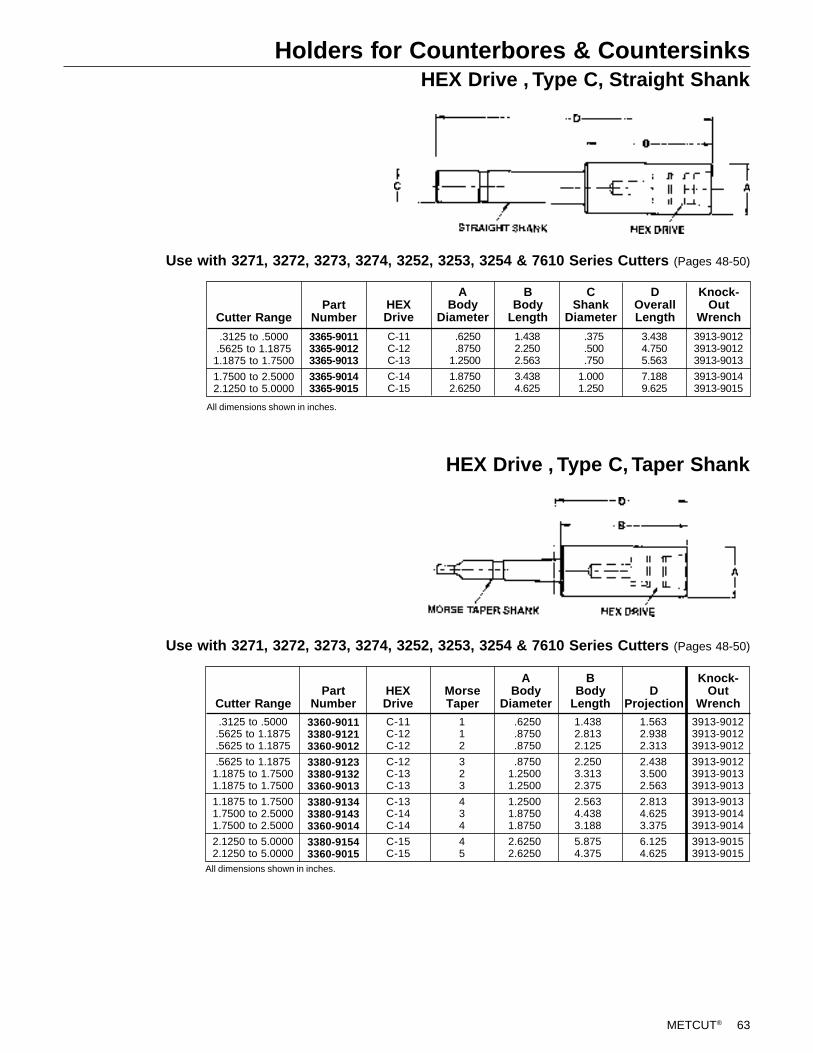
METCUT® 63
Holders for Counterbores & CountersinksHEX Drive , Type C, Straight Shank
HEX Drive , Type C, Taper Shank
Use with 3271, 3272, 3273, 3274, 3252, 3253, 3254 & 7610 Series Cutters (Pages 48-50)
Use with 3271, 3272, 3273, 3274, 3252, 3253, 3254 & 7610 Series Cutters (Pages 48-50)
HEXDrive
C-11C-12C-13
C-14C-15
3.4384.7505.563
7.1889.625
All dimensions shown in inches.
.3125 to .5000.5625 to 1.1875
1.1875 to 1.7500
1.7500 to 2.50002.1250 to 5.0000
Cutter Range
3365-90113365-90123365-9013
3365-90143365-9015
PartNumber
DOverallLength
ABody
Diameter
1.4382.2502.563
3.4384.625
BBody
Length
.6250
.87501.2500
1.87502.6250
.375
.500
.750
1.0001.250
CShank
Diameter
3913-90123913-90123913-9013
3913-90143913-9015
Knock-Out
Wrench
HEXDrive
112
323
434
45
C-11C-12C-12
C-12C-13C-13
C-13C-14C-14
C-15C-15
MorseTaper
1.4382.8132.125
2.2503.3132.375
2.5634.4383.188
5.8754.375
1.5632.9382.313
2.4383.5002.563
2.8134.6253.375
6.1254.625
All dimensions shown in inches.
.3125 to .5000.5625 to 1.1875.5625 to 1.1875
.5625 to 1.18751.1875 to 1.75001.1875 to 1.7500
1.1875 to 1.75001.7500 to 2.50001.7500 to 2.5000
2.1250 to 5.00002.1250 to 5.0000
Cutter Range
3360-90113380-91213360-9012
3380-91233380-91323360-9013
3380-91343380-91433360-9014
3380-91543360-9015
PartNumber
ABody
Diameter
BBody
LengthD
Projection
.6250
.8750
.8750
.87501.25001.2500
1.25001.87501.8750
2.62502.6250
3913-90123913-90123913-9012
3913-90123913-90133913-9013
3913-90133913-90143913-9014
3913-90153913-9015
Knock-Out
Wrench
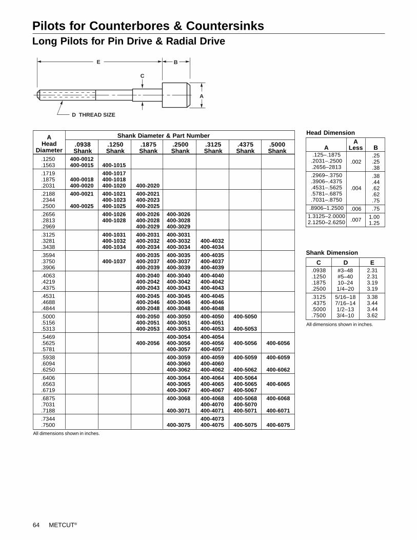
64 METCUT®
Pilots for Counterbores & CountersinksLong Pilots for Pin Drive & Radial Drive
AHead
Diameter
Shank Diameter & Part Number
E
A
B
C
D THREAD SIZE
.1875Shank
.2500Shank
.3125Shank
.4375Shank
.5000Shank
.1250Shank B
ALessA
Head Dimension
.0938Shank
All dimensions shown in inches.
.125–.1875.2031–.2500.2656–2813
.2969–.3750
.3906–.4375
.4531–.5625
.5781–.6875
.7031–.8750
.8906–1.2500
1.3125–2.00002.1250–2.6250
.006
.004
.002
.007
.25
.25
.38
.38
.44
.62
.62
.75
.75
1.001.25
Shank Dimension
.0938
.1250
.1875
.2500
.3125
.4375
.5000
.7500
C D#3–48#5–4010–241/4–20
5/16–187/16–141/2–133/4–10
2.312.313.193.19
3.383.443.443.62
E
All dimensions shown in inches.
.1250 400-0012
.1563 400-0015 400-1015
.1719 400-1017
.1875 400-0018 400-1018
.2031 400-0020 400-1020 400-2020
.2188 400-0021 400-1021 400-2021
.2344 400-1023 400-2023
.2500 400-0025 400-1025 400-2025
.2656 400-1026 400-2026 400-3026
.2813 400-1028 400-2028 400-3028
.2969 400-2029 400-3029
.3125 400-1031 400-2031 400-3031
.3281 400-1032 400-2032 400-3032 400-4032
.3438 400-1034 400-2034 400-3034 400-4034
.3594 400-2035 400-3035 400-4035
.3750 400-1037 400-2037 400-3037 400-4037
.3906 400-2039 400-3039 400-4039
.4063 400-2040 400-3040 400-4040
.4219 400-2042 400-3042 400-4042
.4375 400-2043 400-3043 400-4043
.4531 400-2045 400-3045 400-4045
.4688 400-2046 400-3046 400-4046
.4844 400-2048 400-3048 400-4048
.5000 400-2050 400-3050 400-4050 400-5050
.5156 400-2051 400-3051 400-4051
.5313 400-2053 400-3053 400-4053 400-5053
.5469 400-3054 400-4054
.5625 400-2056 400-3056 400-4056 400-5056 400-6056
.5781 400-3057 400-4057
.5938 400-3059 400-4059 400-5059 400-6059
.6094 400-3060 400-4060
.6250 400-3062 400-4062 400-5062 400-6062
.6406 400-3064 400-4064 400-5064
.6563 400-3065 400-4065 400-5065 400-6065
.6719 400-3067 400-4067 400-5067
.6875 400-3068 400-4068 400-5068 400-6068
.7031 400-4070 400-5070
.7188 400-3071 400-4071 400-5071 400-6071
.7344 400-4073
.7500 400-3075 400-4075 400-5075 400-6075
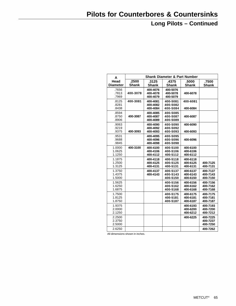
METCUT® 65
Pilots for Counterbores & CountersinksLong Pilots – Continued
400-3078
400-3081
400-3087
400-3093
400-3100
AHead
Diameter.2500Shank
Shank Diameter & Part Number.3125Shank
.4375Shank
.5000Shank
.7500Shank
All dimensions shown in inches.
400-4076400-4078400-4079
400-4081400-4082400-4084
400-4085400-4087400-4089
400-4090400-4092400-4093
400-4095400-4096400-4098
400-4100400-4106400-4112
400-4118400-4125400-4131
400-4137400-4143
400-5076400-5078400-5079
400-5081400-5082400-5084
400-5085400-5087400-5089
400-5090400-5092400-5093
400-5095400-5096400-5098
400-5100400-5106400-5112
400-5118400-5125400-5131
400-5137400-5143400-5150
400-5156400-5162400-5168
400-5175400-5181400-5187
400-6078
400-6081
400-6084
400-6087
400-6090
400-6093
400-6096
400-6100400-6106400-6112
400-6118400-6125400-6131
400-6137400-6143400-6150
400-6156400-6162400-6168
400-6175400-6181400-6187
400-6193400-6200400-6212
400-6225
400-7125400-7131
400-7137400-7143400-7150
400-7156400-7162400-7168
400-7175400-7181400-7187
400-7193400-7200400-7212
400-7225400-7237400-7250
400-7262
.7656
.7813
.7969
.8125
.8281
.8438
.8594
.8750
.8906
.9063
.9219
.9375
.9531
.9688
.9845
1.00001.06251.1250
1.18751.25001.3125
1.37501.43751.5000
1.56251.62501.6875
1.75001.81251.8750
1.93752.00002.1250
2.25002.37502.5000
2.6250
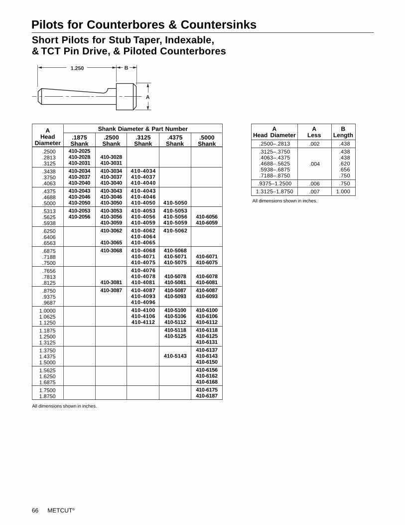
66 METCUT®
Pilots for Counterbores & CountersinksShort Pilots for Stub Taper, Indexable,& TCT Pin Drive, & Piloted Counterbores
410-2025410-2028410-2031
410-2034410-2037410-2040
410-2043410-2046410-2050
410-2053410-2056
AHead
Diameter
Shank Diameter & Part Number.2500Shank
.3125Shank
.4375Shank
.5000Shank
.1875Shank
410-3028410-3031
410-3034410-3037410-3040
410-3043410-3046410-3050
410-3053410-3056410-3059
410-3062
410-3065
410-3068
410-3081
410-3087
410-4034410-4037410-4040
410-4043410-4046410-4050
410-4053410-4056410-4059
410-4062410-4064410-4065
410-4068410-4071410-4075
410-4076410-4078410-4081
410-4087410-4093410-4096
410-4100410-4106410-4112
410-5050
410-5053410-5056410-5059
410-5062
410-5068410-5071410-5075
410-5078410-5081
410-5087410-5093
410-5100410-5106410-5112
410-5118410-5125
410-5143
410-6056410-6059
410-6071410-6075
410-6078410-6081
410-6087410-6093
410-6100410-6106410-6112
410-6118410-6125410-6131
410-6137410-6143410-6150
410-6156410-6162410-6168
410-6175410-6187
.2500–.2813
.3125–.3750
.4063–.4375
.4688–.5625
.5938–.6875
.7188–.8750
.9375–1.2500
1.3125–1.8750
BLength
AHead Diameter
ALess.002
.004
.006
.007
All dimensions shown in inches.
1.250
A
B
.2500
.2813
.3125
.3438
.3750
.4063
.4375
.4688
.5000
.5313
.5625
.5938
.6250
.6406
.6563
.6875
.7188
.7500
.7656
.7813
.8125
.8750
.9375
.9687
1.00001.06251.1250
1.18751.25001.3125
1.37501.43751.5000
1.56251.62501.6875
1.75001.8750
.438
.438
.438
.620
.656
.750
.750
1.000
All dimensions shown in inches.

METCUT® 67
Pilots for Counterbores & Countersinksfor HEX Drive Type A Counterbores
& Type C Carbide -Tipped Counterbores
5001-00105001-00125001-0014
5001-00165001-00185001-0020
5001-00225001-0024
AHead
Diameter#5–40Shank
Shank Diameter & Part Number1/4–20Shank
5002-00185002-0020
5002-00225002-00245002-0026
5002-00285002-00305002-0032
5002-00365002-00405002-0044
5002-00485002-00525002-0056
5/16–18Shank
5003-00245003-0026
5003-00285003-00305003-0032
5003-00365003-00405003-0044
5003-00485003-00525003-0056
5003-00605003-01005003-0104
5003-01085003-01125003-0116
5003-01205003-01245003-0128
7/16–14Shank
5004-00485004-00525004-0056
5004-00605004-01005004-0104
5004-01085004-01125004-0116
5004-01205004-01245004-0128
5004-0132
5004-0140
5004-0148
5004-0156
All dimensions shown in inches.
.1563
.1875
.2188
.2500
.2813
.3125
.3438
.3750
.4063
.4375
.4688
.5000
.5625
.6250
.6875
.7500
.8125
.8750
.93751.00001.0625
1.12501.18751.2500
1.31251.37501.4375
1.50001.56251.6250
1.68751.75001.8125
1.8750
.1562–.2812
.3125–.3750
.4062–.4375
.4688–.5625.6250
.6875–.8750
.9375–1.00001.0600–1.1875
1.2500–1.8750
A A Less B.002
.004
.006
.007
.38
.38
.44
.56
.62
.75
.751.00
1.25
Head Dimension
.1250
.2500
.3125
.4375
#5–401/4–20
5/16–18
7/16–14
1.4381.6251.875
2.750
A-1A-2, C-12A-3, C-13
A-4, C-14
C D E Used On
All dimensions shown in inches.
Shank Dimension
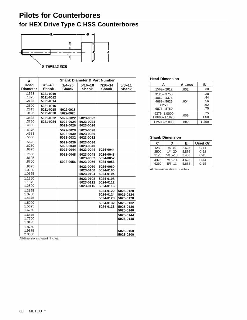
68 METCUT®
Pilots for Counterboresfor HEX Drive Type C HSS Counterbores
5021-00105021-00125021-0014
5021-00165021-00185021-0020
5021-00225021-0024
AHead
Diameter#5–40Shank
Shank Diameter & Part Number1/4–20Shank
5022-00185022-0020
5022-00225022-00245022-0026
5022-00285022-00305022-0032
5022-00365022-00405022-0044
5022-0048
5022-0056
5/16–18Shank
5023-00225023-00245023-0026
5023-00285023-00305023-0032
5023-00365023-00405023-0044
5023-00485023-00525023-0056
5023-00605023-01005023-0104
5023-01085023-01125023-0116
7/16–14Shank
5024-0044
5024-00485024-00525024-0056
5024-00605024-01005024-0104
5024-01085024-01125024-0116
5024-01205024-01245024-0128
5024-01325024-0136
5/8–11Shank
5025-01205025-01245025-0128
5025-01325025-01365025-0140
5025-01445025-0148
5025-01605025-0200
All dimensions shown in inches.
.1563
.1875
.2188
.2500
.2813
.3125
.3438
.3750
.4063
.4375
.4688
.5000
.5625
.6250
.6875
.7500
.8125
.8750
.93751.00001.0625
1.12501.18751.2500
1.31251.37501.4375
1.50001.56251.6250
1.68751.75001.8125
1.87501.93752.0000
.1562–.2812
.3125–.3750
.4062–.4375
.4688–.5625.6250
.6875–.8750
.9375–1.00001.0600–1.1875
1.2500–2.000
A A Less B
Head Dimension
.002
.004
.006
.007
.38
.38
.44
.56
.62
.75
.751.00
1.250
.1250
.2500
.3125
.4375
.6250
#5–401/4–205/16–18
7/16–145/8–11
2.6252.8753.438
4.6255.688
C-11C-12C-13
C-14C-15
C D E Used On
All dimensions shown in inches.
Shank Dimension
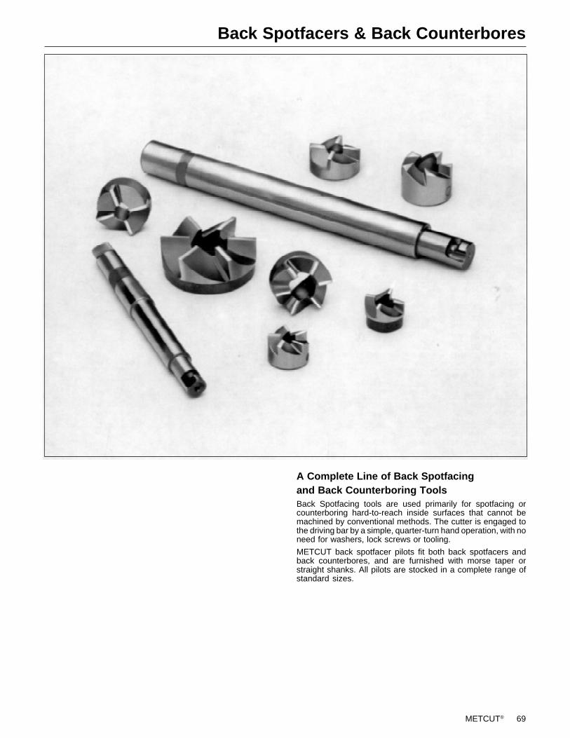
METCUT® 69
Back Spotfacers & Back Counterbores
A Complete Line of Back Spotfacingand Back Counterboring ToolsBack Spotfacing tools are used primarily for spotfacing orcounterboring hard-to-reach inside surfaces that cannot bemachined by conventional methods. The cutter is engaged tothe driving bar by a simple, quarter-turn hand operation, with noneed for washers, lock screws or tooling.
METCUT back spotfacer pilots fit both back spotfacers andback counterbores, and are furnished with morse taper orstraight shanks. All pilots are stocked in a complete range ofstandard sizes.
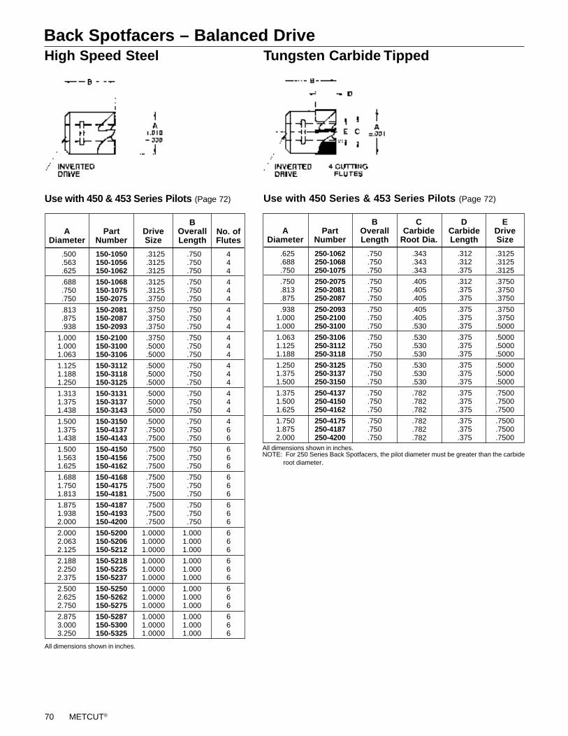
70 METCUT®
Back Spotfacers – Balanced DriveTungsten Carbide Tipped
Use with 450 Series & 453 Series Pilots (Page 72)
250-1062250-1068250-1075
250-2075250-2081250-2087
250-2093250-2100250-3100
250-3106250-3112250-3118
250-3125250-3137250-3150
250-4137250-4150250-4162
250-4175250-4187250-4200
PartNumber
All dimensions shown in inches.NOTE: For 250 Series Back Spotfacers, the pilot diameter must be greater than the carbide root diameter.
ADiameter
.750
.750
.750
.750
.750
.750
.750
.750
.750
.750
.750
.750
.750
.750
.750
.750
.750
.750
.750
.750
.750
.343
.343
.343
.405
.405
.405
.405
.405
.530
.530
.530
.530
.530
.530
.530
.782
.782
.782
.782
.782
.782
BOverallLength
CCarbide
Root Dia.
.312
.312
.375
.312
.375
.375
.375
.375
.375
.375
.375
.375
.375
.375
.375
.375
.375
.375
.375
.375
.375
DCarbideLength
.3125
.3125
.3125
.3750
.3750
.3750
.3750
.3750
.5000
.5000
.5000
.5000
.5000
.5000
.5000
.7500
.7500
.7500
.7500
.7500
.7500
EDriveSize
.625
.688
.750
.750
.813
.875
.9381.0001.000
1.0631.1251.188
1.2501.3751.500
1.3751.5001.625
1.7501.8752.000
High Speed Steel
150-1050150-1056150-1062
150-1068150-1075150-2075
150-2081150-2087150-2093
150-2100150-3100150-3106
150-3112150-3118150-3125
150-3131150-3137150-3143
150-3150150-4137150-4143
150-4150150-4156150-4162
150-4168150-4175150-4181
150-4187150-4193150-4200
150-5200150-5206150-5212
150-5218150-5225150-5237
150-5250150-5262150-5275
150-5287150-5300150-5325
PartNumber
DriveSize
All dimensions shown in inches.
ADiameter
.500
.563
.625
.688
.750
.750
.813
.875
.938
1.0001.0001.063
1.1251.1881.250
1.3131.3751.438
1.5001.3751.438
1.5001.5631.625
1.6881.7501.813
1.8751.9382.000
2.0002.0632.125
2.1882.2502.375
2.5002.6252.750
2.8753.0003.250
.3125
.3125
.3125
.3125
.3125
.3750
.3750
.3750
.3750
.3750
.5000
.5000
.5000
.5000
.5000
.5000
.5000
.5000
.5000
.7500
.7500
.7500
.7500
.7500
.7500
.7500
.7500
.7500
.7500
.7500
1.00001.00001.0000
1.00001.00001.0000
1.00001.00001.0000
1.00001.00001.0000
BOverallLength
.750
.750
.750
.750
.750
.750
.750
.750
.750
.750
.750
.750
.750
.750
.750
.750
.750
.750
.750
.750
.750
.750
.750
.750
.750
.750
.750
.750
.750
.750
1.0001.0001.000
1.0001.0001.000
1.0001.0001.000
1.0001.0001.000
No. ofFlutes
444
444
444
444
444
444
466
666
666
666
666
666
666
666
Use with 450 & 453 Series Pilots (Page 72)
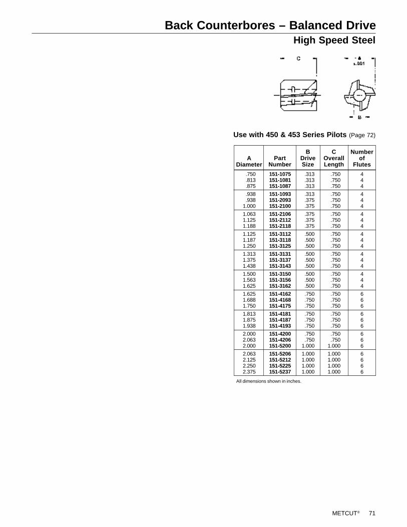
METCUT® 71
Back Counterbores – Balanced DriveHigh Speed Steel
Use with 450 & 453 Series Pilots (Page 72)
COverallLength
444
444
444
444
444
444
666
666
666
6666
Numberof
FlutesPart
Number
151-1075151-1081151-1087
151-1093151-2093151-2100
151-2106151-2112151-2118
151-3112151-3118151-3125
151-3131151-3137151-3143
151-3150151-3156151-3162
151-4162151-4168151-4175
151-4181151-4187151-4193
151-4200151-4206151-5200
151-5206151-5212151-5225151-5237
BDriveSize
ADiameter
All dimensions shown in inches.
.750
.813
.875
.938
.9381.000
1.0631.1251.188
1.1251.1871.250
1.3131.3751.438
1.5001.5631.625
1.6251.6881.750
1.8131.8751.938
2.0002.0632.000
2.0632.1252.2502.375
.313
.313
.313
.313
.375
.375
.375
.375
.375
.500
.500
.500
.500
.500
.500
.500
.500
.500
.750
.750
.750
.750
.750
.750
.750
.7501.000
1.0001.0001.0001.000
.750
.750
.750
.750
.750
.750
.750
.750
.750
.750
.750
.750
.750
.750
.750
.750
.750
.750
.750
.750
.750
.750
.750
.750
.750
.7501.000
1.0001.0001.0001.000

72 METCUT®
Pilots for Balanced Drive Back Spotfacers & Back Counterboreswith Straight Shank
APilot
Diameter*
CBody
Length
DInverted
DrivePart
Number
453-1031453-1034453-1037
453-1040453-1043453-1046
453-1050453-1053453-2037
453-2040453-2043453-2046
453-2050453-2053453-2056
453-2059453-2062453-2065
453-3050453-3053453-3056
453-3059453-3062453-3065
453-3068453-3075453-3078
453-3081453-3087453-3090
453-3103453-4075453-4081
453-4087453-4093453-4100
453-4112453-4125453-4137
453-5100453-5112453-5125
453-5137453-5150453-5162
BShank
Dia.
2.5002.5002.500
2.5002.5002.500
2.5002.5002.500
2.5002.5002.500
2.5002.5002.500
2.5002.5002.500
2.5002.5002.500
2.5002.5002.500
2.5002.5002.500
3.5003.5003.500
3.5003.5003.500
3.5003.5003.500
3.5003.5003.500
3.5003.5003.500
3.5005.0005.000
All dimensions shown in inches.*Finish ground for running fit in nominal size hole.
.3125
.3438
.3750
.4063
.4375
.4688
.5000
.5313
.3750
.4063
.4375
.4688
.5000
.5313
.5625
.5938
.6250
.6563
.5000
.5313
.5625
.5938
.6250
.6563
.6875
.7500
.7813
.8125
.8750
.9063
1.0313.7500.8125
.8750
.93751.0000
1.12501.25001.3750
1.00001.12501.2500
1.37501.50001.6250
.3125
.3125
.3125
.3125
.3125
.3125
.3125
.3125
.3750
.3750
.3750
.3750
.3750
.3750
.3750
.3750
.3750
.3750
.5000
.5000
.5000
.5000
.5000
.5000
.5000
.5000
.5000
.5000
.5000
.5000
.5000
.7500
.7500
.7500
.7500
.7500
.7500
.7500
.7500
1.00001.00001.0000
1.00001.00001.0000
.500
.500
.500
.500
.500
.500
.500
.500
.500
.500
.500
.500
.500
.500
.500
.500
.500
.500
.500
.500
.500
.500
.500
.500
.500
.500
.500
.500
.500
.500
.500
.750
.750
.750
.750
.750
.750
.750
.750
1.0001.0001.000
1.0001.0001.000
Use with 150 & 250 Series Back Spotfacers (Page 70)
and 151 Series Back Counterbores (Page 71)
with Taper Shank
A
C
B
E
D DRIVE SIZE
Use with 150 & 250 Series Back Spotfacers (Page 70)
and 151 Series Back Counterbores (Page 71)
450-1031450-1034450-1037
450-1040450-1043450-1046
450-1050450-1053450-2037
450-2040450-2043450-2046
450-2050450-2053450-2056
450-2059450-2062450-2065
450-3050450-3053450-3056
450-3059450-3062450-3065
450-3068450-3075450-3078
450-3081450-3087450-3090
450-3103450-4075450-4081
450-4087450-4093450-4100
450-4112450-4125450-4137
450-5100450-5112450-5125
450-5137450-5150450-5162
PartNumber
APilot
Diameter*
222
222
222
222
222
222
222
222
222
222
233
333
333
444
444
2.5002.5002.500
2.5002.5002.500
2.5002.5002.500
2.5002.5002.500
2.5002.5002.500
2.5002.5002.500
2.5002.5002.500
2.5002.5002.500
2.5002.5002.500
3.5003.5003.500
3.5003.5003.500
3.5003.5003.500
3.5003.5003.500
3.5003.5003.500
3.5005.0005.000
MorseTaperShank
BBody
Length
CInverted
Drive
.3125
.3438
.3750
.4063
.4375
.4688
.5000
.5313
.3750
.4063
.4375
.4688
.5000
.5313
.5625
.5938
.6250
.6563
.5000
.5313
.5625
.5938
.6250
.6563
.6875
.7500
.7813
.8125
.8750
.9063
1.0313.7500.8125
.8750
.93751.0000
1.12501.25001.3750
1.00001.12501.2500
1.37501.50001.6250
.3125
.3125
.3125
.3125
.3125
.3125
.3125
.3125
.3750
.3750
.3750
.3750
.3750
.3750
.3750
.3750
.3750
.3750
.5000
.5000
.5000
.5000
.5000
.5000
.5000
.5000
.5000
.5000
.5000
.5000
.5000
.7500
.7500
.7500
.7500
.7500
.7500
.7500
.7500
1.00001.00001.0000
1.00001.00001.0000
All dimensions shown in inches.*Finish ground for running fit in nominal size hole.
A
B
MORSE TAPER SHANK C DRIVE SIZE
EShankLength
2.0002.0002.000
2.0002.0002.000
2.0002.0002.000
2.0002.0002.000
2.0002.0002.000
2.0002.0002.000
2.0002.0002.000
2.0002.0002.000
2.0002.0002.000
2.0002.0002.000
2.0002.2502.250
2.2502.2502.250
2.2502.2502.250
2.5002.5002.500
2.5002.5002.500
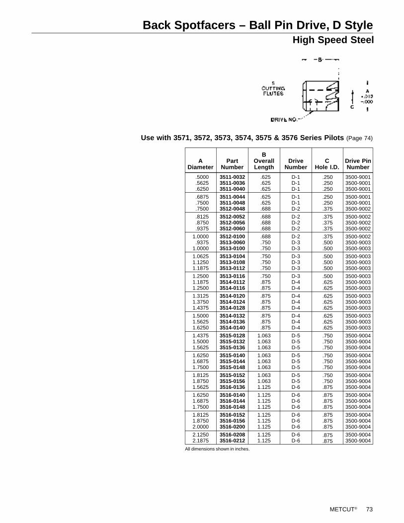
METCUT® 73
Back Spotfacers – Ball Pin Drive, D StyleHigh Speed Steel
Use with 3571, 3572, 3573, 3574, 3575 & 3576 Series Pilots (Page 74)
3511-00323511-00363511-0040
3511-00443511-00483512-0048
3512-00523512-00563512-0060
3512-01003513-00603513-0100
3513-01043513-01083513-0112
3513-01163514-01123514-0116
3514-01203514-01243514-0128
3514-01323514-01363514-0140
3515-01283515-01323515-0136
3515-01403515-01443515-0148
3515-01523515-01563516-0136
3516-01403516-01443516-0148
3516-01523516-01563516-0200
3516-02083516-0212
PartNumber
D-1D-1D-1
D-1D-1D-2
D-2D-2D-2
D-2D-3D-3
D-3D-3D-3
D-3D-4D-4
D-4D-4D-4
D-4D-4D-4
D-5D-5D-5
D-5D-5D-5
D-5D-5D-6
D-6D-6D-6
D-6D-6D-6
D-6D-6
DriveNumber
.250
.250
.250
.250
.250
.375
.375
.375
.375
.375
.500
.500
.500
.500
.500
.500
.625
.625
.625
.625
.625
.625
.625
.625
.750
.750
.750
.750
.750
.750
.750
.750
.875
.875
.875
.875
.875
.875
.875
.875
.875
3500-90013500-90013500-9001
3500-90013500-90013500-9002
3500-90023500-90023500-9002
3500-90023500-90033500-9003
3500-90033500-90033500-9003
3500-90033500-90033500-9003
3500-90033500-90033500-9003
3500-90033500-90033500-9003
3500-90043500-90043500-9004
3500-90043500-90043500-9004
3500-90043500-90043500-9004
3500-90043500-90043500-9004
3500-90043500-90043500-9004
3500-90043500-9004
Drive PinNumber
All dimensions shown in inches.
ADiameter
BOverallLength
CHole I.D.
.5000
.5625
.6250
.6875
.7500
.7500
.8125
.8750
.9375
1.0000.9375
1.0000
1.06251.12501.1875
1.25001.18751.2500
1.31251.37501.4375
1.50001.56251.6250
1.43751.50001.5625
1.62501.68751.7500
1.81251.87501.5625
1.62501.68751.7500
1.81251.87502.0000
2.12502.1875
.625
.625
.625
.625
.625
.688
.688
.688
.688
.688
.750
.750
.750
.750
.750
.750
.875
.875
.875
.875
.875
.875
.875
.875
1.0631.0631.063
1.0631.0631.063
1.0631.0631.125
1.1251.1251.125
1.1251.1251.125
1.1251.125
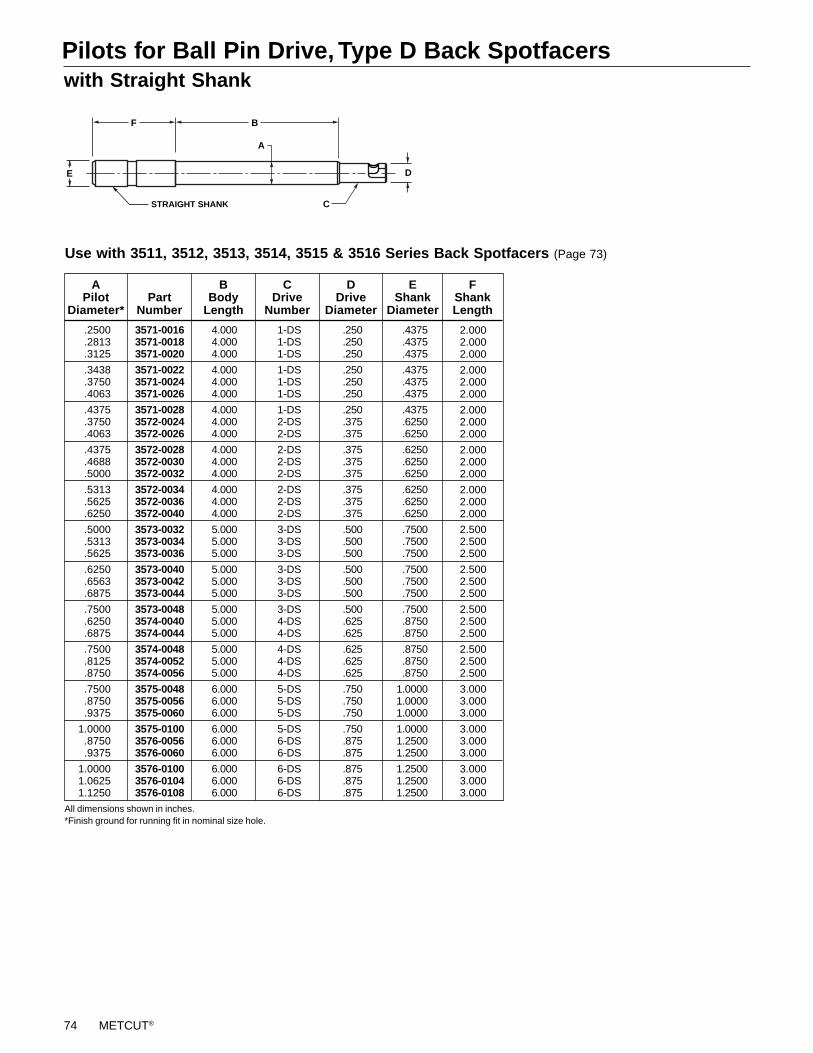
74 METCUT®
Pilots for Ball Pin Drive, Type D Back Spotfacerswith Straight Shank
A
B
E D
F
CSTRAIGHT SHANK
Use with 3511, 3512, 3513, 3514, 3515 & 3516 Series Back Spotfacers (Page 73)
3571-00163571-00183571-0020
3571-00223571-00243571-0026
3571-00283572-00243572-0026
3572-00283572-00303572-0032
3572-00343572-00363572-0040
3573-00323573-00343573-0036
3573-00403573-00423573-0044
3573-00483574-00403574-0044
3574-00483574-00523574-0056
3575-00483575-00563575-0060
3575-01003576-00563576-0060
3576-01003576-01043576-0108
PartNumber
1-DS1-DS1-DS
1-DS1-DS1-DS
1-DS2-DS2-DS
2-DS2-DS2-DS
2-DS2-DS2-DS
3-DS3-DS3-DS
3-DS3-DS3-DS
3-DS4-DS4-DS
4-DS4-DS4-DS
5-DS5-DS5-DS
5-DS6-DS6-DS
6-DS6-DS6-DS
.250
.250
.250
.250
.250
.250
.250
.375
.375
.375
.375
.375
.375
.375
.375
.500
.500
.500
.500
.500
.500
.500
.625
.625
.625
.625
.625
.750
.750
.750
.750
.875
.875
.875
.875
.875
4.0004.0004.000
4.0004.0004.000
4.0004.0004.000
4.0004.0004.000
4.0004.0004.000
5.0005.0005.000
5.0005.0005.000
5.0005.0005.000
5.0005.0005.000
6.0006.0006.000
6.0006.0006.000
6.0006.0006.000
2.0002.0002.000
2.0002.0002.000
2.0002.0002.000
2.0002.0002.000
2.0002.0002.000
2.5002.5002.500
2.5002.5002.500
2.5002.5002.500
2.5002.5002.500
3.0003.0003.000
3.0003.0003.000
3.0003.0003.000
FShankLength
EShank
Diameter
DDrive
Diameter
CDrive
Number
BBody
Length
APilot
Diameter*
.2500
.2813
.3125
.3438
.3750
.4063
.4375
.3750
.4063
.4375
.4688
.5000
.5313
.5625
.6250
.5000
.5313
.5625
.6250
.6563
.6875
.7500
.6250
.6875
.7500
.8125
.8750
.7500
.8750
.9375
1.0000.8750.9375
1.00001.06251.1250
.4375
.4375
.4375
.4375
.4375
.4375
.4375
.6250
.6250
.6250
.6250
.6250
.6250
.6250
.6250
.7500
.7500
.7500
.7500
.7500
.7500
.7500
.8750
.8750
.8750
.8750
.8750
1.00001.00001.0000
1.00001.25001.2500
1.25001.25001.2500
All dimensions shown in inches.*Finish ground for running fit in nominal size hole.
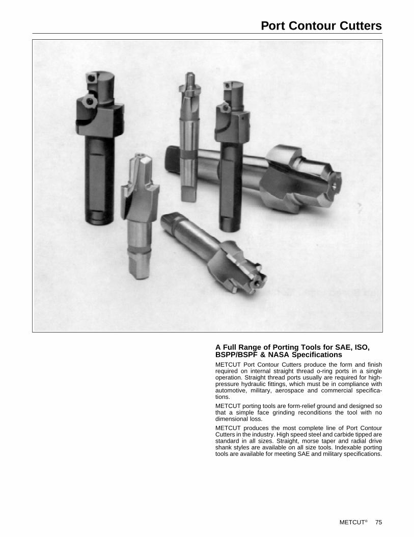
METCUT® 75
Port Contour Cutters
A Full Range of Porting Tools for SAE, ISO,BSPP/BSPF & NASA SpecificationsMETCUT Port Contour Cutters produce the form and finishrequired on internal straight thread o-ring ports in a singleoperation. Straight thread ports usually are required for high-pressure hydraulic fittings, which must be in compliance withautomotive, military, aerospace and commercial specifica-tions.
METCUT porting tools are form-relief ground and designed sothat a simple face grinding reconditions the tool with nodimensional loss.
METCUT produces the most complete line of Port ContourCutters in the industry. High speed steel and carbide tipped arestandard in all sizes. Straight, morse taper and radial driveshank styles are available on all size tools. Indexable portingtools are available for meeting SAE and military specifications.
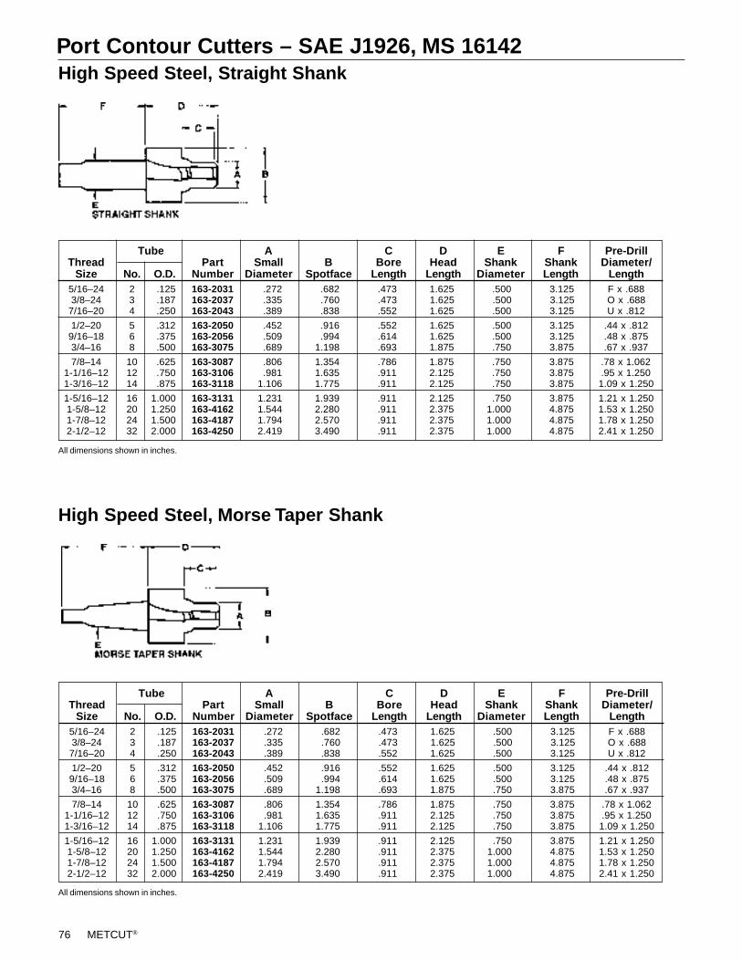
76 METCUT®
Port Contour Cutters – SAE J1926, MS 16142High Speed Steel, Straight Shank
High Speed Steel, Morse Taper Shank
All dimensions shown in inches.
All dimensions shown in inches.
Tube A C D E F Pre-DrillThread Part Small B Bore Head Shank Shank Diameter/
Size No. O.D. Number Diameter Spotface Length Length Diameter Length Length5/16–24 2 .125 163-2031 .272 .682 .473 1.625 .500 3.125 F x .6883/8–24 3 .187 163-2037 .335 .760 .473 1.625 .500 3.125 O x .688
7/16–20 4 .250 163-2043 .389 .838 .552 1.625 .500 3.125 U x .812
1/2–20 5 .312 163-2050 .452 .916 .552 1.625 .500 3.125 .44 x .8129/16–18 6 .375 163-2056 .509 .994 .614 1.625 .500 3.125 .48 x .8753/4–16 8 .500 163-3075 .689 1.198 .693 1.875 .750 3.875 .67 x .937
7/8–14 10 .625 163-3087 .806 1.354 .786 1.875 .750 3.875 .78 x 1.0621-1/16–12 12 .750 163-3106 .981 1.635 .911 2.125 .750 3.875 .95 x 1.2501-3/16–12 14 .875 163-3118 1.106 1.775 .911 2.125 .750 3.875 1.09 x 1.250
1-5/16–12 16 1.000 163-3131 1.231 1.939 .911 2.125 .750 3.875 1.21 x 1.2501-5/8–12 20 1.250 163-4162 1.544 2.280 .911 2.375 1.000 4.875 1.53 x 1.2501-7/8–12 24 1.500 163-4187 1.794 2.570 .911 2.375 1.000 4.875 1.78 x 1.2502-1/2–12 32 2.000 163-4250 2.419 3.490 .911 2.375 1.000 4.875 2.41 x 1.250
Tube A C D E F Pre-DrillThread Part Small B Bore Head Shank Shank Diameter/
Size No. O.D. Number Diameter Spotface Length Length Diameter Length Length5/16–24 2 .125 163-2031 .272 .682 .473 1.625 .500 3.125 F x .6883/8–24 3 .187 163-2037 .335 .760 .473 1.625 .500 3.125 O x .6887/16–20 4 .250 163-2043 .389 .838 .552 1.625 .500 3.125 U x .812
1/2–20 5 .312 163-2050 .452 .916 .552 1.625 .500 3.125 .44 x .8129/16–18 6 .375 163-2056 .509 .994 .614 1.625 .500 3.125 .48 x .8753/4–16 8 .500 163-3075 .689 1.198 .693 1.875 .750 3.875 .67 x .937
7/8–14 10 .625 163-3087 .806 1.354 .786 1.875 .750 3.875 .78 x 1.0621-1/16–12 12 .750 163-3106 .981 1.635 .911 2.125 .750 3.875 .95 x 1.2501-3/16–12 14 .875 163-3118 1.106 1.775 .911 2.125 .750 3.875 1.09 x 1.250
1-5/16–12 16 1.000 163-3131 1.231 1.939 .911 2.125 .750 3.875 1.21 x 1.2501-5/8–12 20 1.250 163-4162 1.544 2.280 .911 2.375 1.000 4.875 1.53 x 1.2501-7/8–12 24 1.500 163-4187 1.794 2.570 .911 2.375 1.000 4.875 1.78 x 1.2502-1/2–12 32 2.000 163-4250 2.419 3.490 .911 2.375 1.000 4.875 2.41 x 1.250
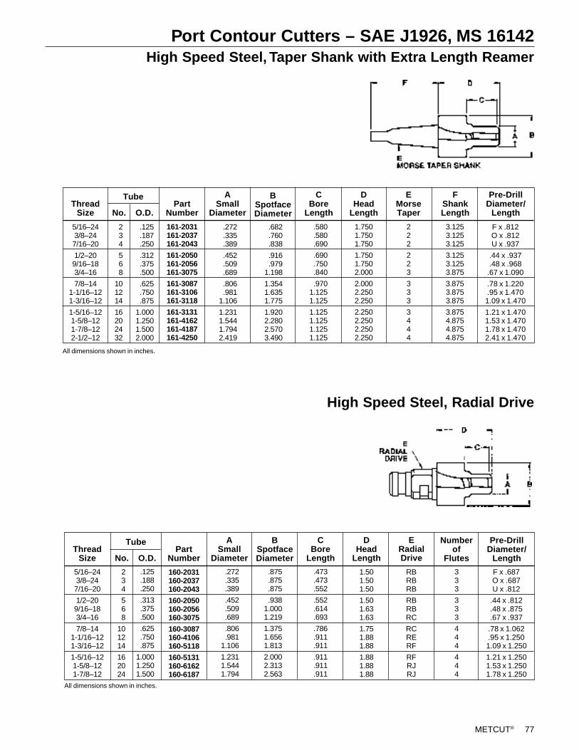
METCUT® 77
Port Contour Cutters – SAE J1926, MS 16142High Speed Steel, Taper Shank with Extra Length Reamer
High Speed Steel, Radial Drive
ThreadSize No. O.D.
Tube
160-2031160-2037160-2043
160-2050160-2056160-3075
160-3087160-4106160-5118
160-5131160-6162160-6187
PartNumber
ASmall
Diameter
CBore
Length
DHead
Length
BSpotfaceDiameter
333
333
444
444
Pre-DrillDiameter/
Length
Numberof
Flutes
F x .687O x .687U x .812
.44 x .812
.48 x .875
.67 x .937
.78 x 1.062
.95 x 1.2501.09 x 1.250
1.21 x 1.2501.53 x 1.2501.78 x 1.250
.473
.473
.552
.552
.614
.693
.786
.911
.911
.911
.911
.911
234
568
101214
162024
5/16–243/8–247/16–20
1/2–209/16–183/4–16
7/8–141-1/16–121-3/16–12
1-5/16–121-5/8–121-7/8–12
RBRBRB
RBRBRC
RCRERF
RFRJRJ
1.501.501.50
1.501.631.63
1.751.881.88
1.881.881.88
All dimensions shown in inches.
.125
.188
.250
.313
.375
.500
.625
.750
.875
1.0001.2501.500
.272
.335
.389
.452
.509
.689
.806
.9811.106
1.2311.5441.794
.875
.875
.875
.9381.0001.219
1.3751.6561.813
2.0002.3132.563
All dimensions shown in inches.
5/16–243/8–247/16–20
1/2–209/16–183/4–16
7/8–141-1/16–121-3/16–12
1-5/16–121-5/8–121-7/8–122-1/2–12
ThreadSize No. O.D.
234
568
101214
16202432
Tube
161-2031161-2037161-2043
161-2050161-2056161-3075
161-3087161-3106161-3118
161-3131161-4162161-4187161-4250
PartNumber
3.1253.1253.125
3.1253.1253.875
3.8753.8753.875
3.8754.8754.8754.875
222
223
333
3444
1.7501.7501.750
1.7501.7502.000
2.0002.2502.250
2.2502.2502.2502.250
FShankLength
EMorseTaper
DHead
Length
CBore
Length
ASmall
Diameter
BSpotfaceDiameter
.125
.187
.250
.312
.375
.500
.625
.750
.875
1.0001.2501.5002.000
.272
.335
.389
.452
.509
.689
.806
.9811.106
1.2311.5441.7942.419
.682
.760
.838
.916
.9791.198
1.3541.6351.775
1.9202.2802.5703.490
.580
.580
.690
.690
.750
.840
.9701.1251.125
1.1251.1251.1251.125
Pre-DrillDiameter/
Length
F x .812O x .812U x .937
.44 x .937
.48 x .968.67 x 1.090
.78 x 1.220
.95 x 1.4701.09 x 1.470
1.21 x 1.4701.53 x 1.4701.78 x 1.4702.41 x 1.470
ERadialDrive
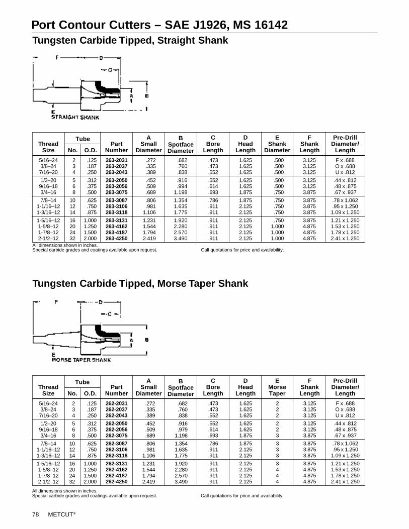
78 METCUT®
Port Contour Cutters – SAE J1926, MS 16142Tungsten Carbide Tipped, Straight Shank
Tungsten Carbide Tipped, Morse Taper Shank
5/16–243/8–247/16–20
1/2–209/16–183/4–16
7/8–141-1/16–121-3/16–12
1-5/16–121-5/8–121-7/8–122-1/2–12
ThreadSize No. O.D.
234
568
101214
16202432
Tube
263-2031263-2037263-2043
263-2050263-2056263-3075
263-3087263-3106263-3118
263-3131263-4162263-4187263-4250
PartNumber
ASmall
Diameter
F x .688O x .688U x .812
.44 x .812
.48 x .875
.67 x .937
.78 x 1.062
.95 x 1.2501.09 x 1.250
1.21 x 1.2501.53 x 1.2501.78 x 1.2502.41 x 1.250
Pre-DrillDiameter/
Length
3.1253.1253.125
3.1253.1253.875
3.8753.8753.875
3.8754.8754.8754.875
1.6251.6251.625
1.6251.6251.875
1.8752.1252.125
2.1252.1252.1252.125
.473
.473
.552
.552
.614
.693
.786
.911
.911
.911
.911
.911
.911
CBore
Length
FShankLength
EShank
Diameter
DHead
Length
BSpotfaceDiameter
.125
.187
.250
.312
.375
.500
.625
.750
.875
1.0001.2501.5002.000
.272
.335
.389
.452
.509
.689
.806
.9811.106
1.2311.5441.7942.419
.682
.760
.838
.916
.9941.198
1.3541.6351.775
1.9202.2802.5703.490
.500
.500
.500
.500
.500
.750
.750
.750
.750
.7501.0001.0001.000
All dimensions shown in inches.Special carbide grades and coatings available upon request. Call quotations for price and availability.
5/16–243/8–247/16–20
1/2–209/16–183/4–16
7/8–141-1/16–121-3/16–12
1-5/16–121-5/8–121-7/8–122-1/2–12
ThreadSize No. O.D.
234
568
101214
16202432
Tube
F x .688O x .688U x .812
.44 x .812
.48 x .875
.67 x .937
.78 x 1.062
.95 x 1.2501.09 x 1.250
1.21 x 1.2501.53 x 1.2501.78 x 1.2502.41 x 1.250
Pre-DrillDiameter/
Length
3.1253.1253.125
3.1253.1253.875
3.8753.8753.875
3.8754.8754.8754.875
222
223
333
3444
1.6251.6251.625
1.6251.6251.875
1.8752.1252.125
2.1252.1252.1252.125
FShankLength
EMorseTaper
DHead
Length
.473
.473
.552
.552
.614
.693
.786
.911
.911
.911
.911
.911
.911
CBore
Length
BSpotfaceDiameter
ASmall
Diameter
262-2031262-2037262-2043
262-2050262-2056262-3075
262-3087262-3106262-3118
262-3131262-4162262-4187262-4250
PartNumber
.272
.335
.389
.452
.509
.689
.806
.9811.106
1.2311.5441.7942.419
.682
.760
.838
.916
.9791.198
1.3541.6351.775
1.9202.2802.5703.490
.125
.187
.250
.312
.375
.500
.625
.750
.875
1.0001.2501.5002.000
All dimensions shown in inches.Special carbide grades and coatings available upon request. Call quotations for price and availability.
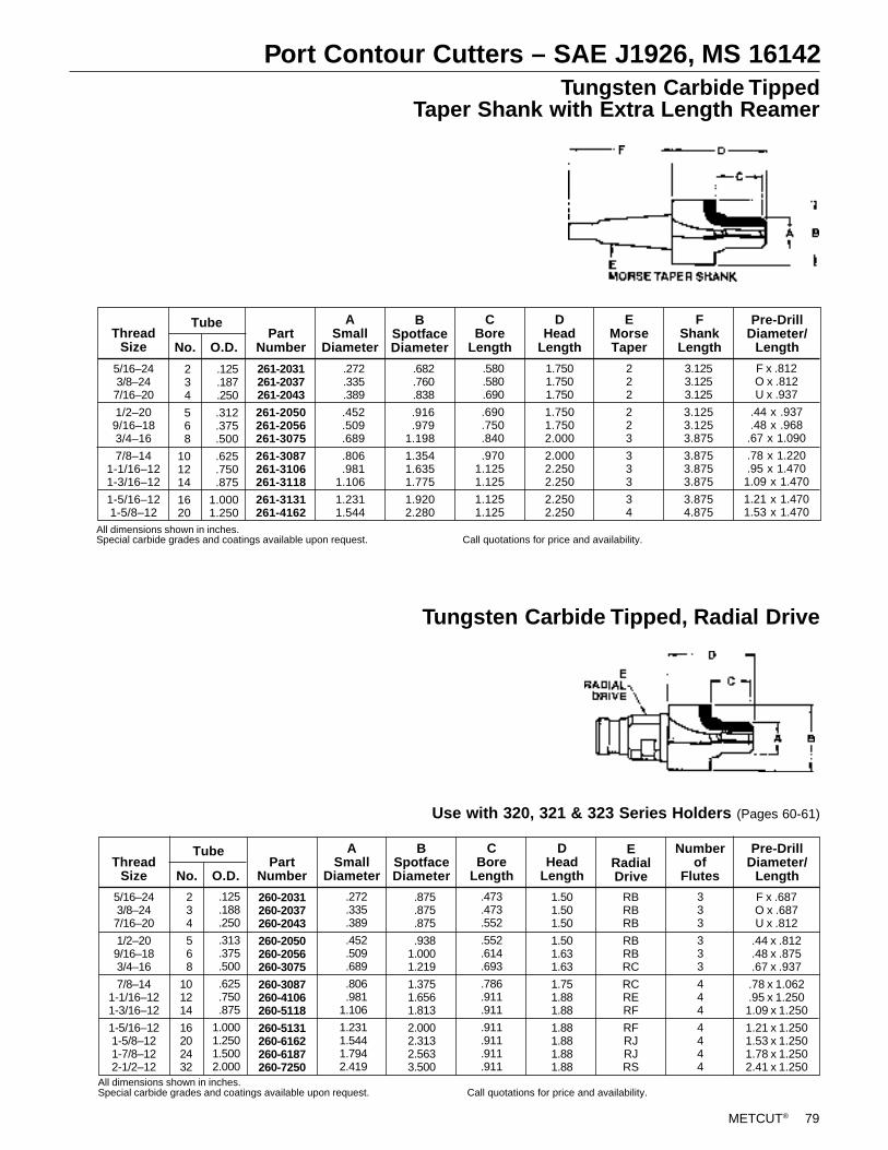
METCUT® 79
Port Contour Cutters – SAE J1926, MS 16142Tungsten Carbide Tipped
Taper Shank with Extra Length Reamer
Tungsten Carbide Tipped, Radial Drive
Use with 320, 321 & 323 Series Holders (Pages 60-61)
3.1253.1253.125
3.1253.1253.875
3.8753.8753.875
3.8754.875
222
223
333
34
FShankLength
EMorseTaper
1.7501.7501.750
1.7501.7502.000
2.0002.2502.250
2.2502.250
DHead
Length
CBore
Length
ASmall
Diameter
BSpotfaceDiameter
261-2031261-2037261-2043
261-2050261-2056261-3075
261-3087261-3106261-3118
261-3131261-4162
PartNumberNo. O.D.
234
568
101214
1620
Tube
5/16–243/8–247/16–20
1/2–209/16–183/4–16
7/8–141-1/16–121-3/16–12
1-5/16–121-5/8–12
ThreadSize
.125
.187
.250
.312
.375
.500
.625
.750
.875
1.0001.250
.272
.335
.389
.452
.509
.689
.806
.9811.106
1.2311.544
.682
.760
.838
.916
.9791.198
1.3541.6351.775
1.9202.280
.580
.580
.690
.690
.750
.840
.9701.1251.125
1.1251.125
Pre-DrillDiameter/
Length
F x .812O x .812U x .937
.44 x .937
.48 x .968.67 x 1.090
.78 x 1.220
.95 x 1.4701.09 x 1.470
1.21 x 1.4701.53 x 1.470
ThreadSize No. O.D.
Tube
260-2031260-2037260-2043
260-2050260-2056260-3075
260-3087260-4106260-5118
260-5131260-6162260-6187260-7250
PartNumber
ASmall
Diameter
CBore
Length
DHead
Length
BSpotfaceDiameter
333
333
444
4444
Pre-DrillDiameter/
Length
Numberof
Flutes
F x .687O x .687U x .812
.44 x .812
.48 x .875
.67 x .937
.78 x 1.062
.95 x 1.2501.09 x 1.250
1.21 x 1.2501.53 x 1.2501.78 x 1.2502.41 x 1.250
.473
.473
.552
.552
.614
.693
.786
.911
.911
.911
.911
.911
.911
234
568
101214
16202432
5/16–243/8–247/16–20
1/2–209/16–183/4–16
7/8–141-1/16–121-3/16–12
1-5/16–121-5/8–121-7/8–122-1/2–12
RBRBRB
RBRBRC
RCRERF
RFRJRJRS
1.501.501.50
1.501.631.63
1.751.881.88
1.881.881.881.88
.125
.188
.250
.313
.375
.500
.625
.750
.875
1.0001.2501.5002.000
.272
.335
.389
.452
.509
.689
.806
.9811.106
1.2311.5441.7942.419
.875
.875
.875
.9381.0001.219
1.3751.6561.813
2.0002.3132.5633.500
ERadialDrive
All dimensions shown in inches.Special carbide grades and coatings available upon request. Call quotations for price and availability.
All dimensions shown in inches.Special carbide grades and coatings available upon request. Call quotations for price and availability.
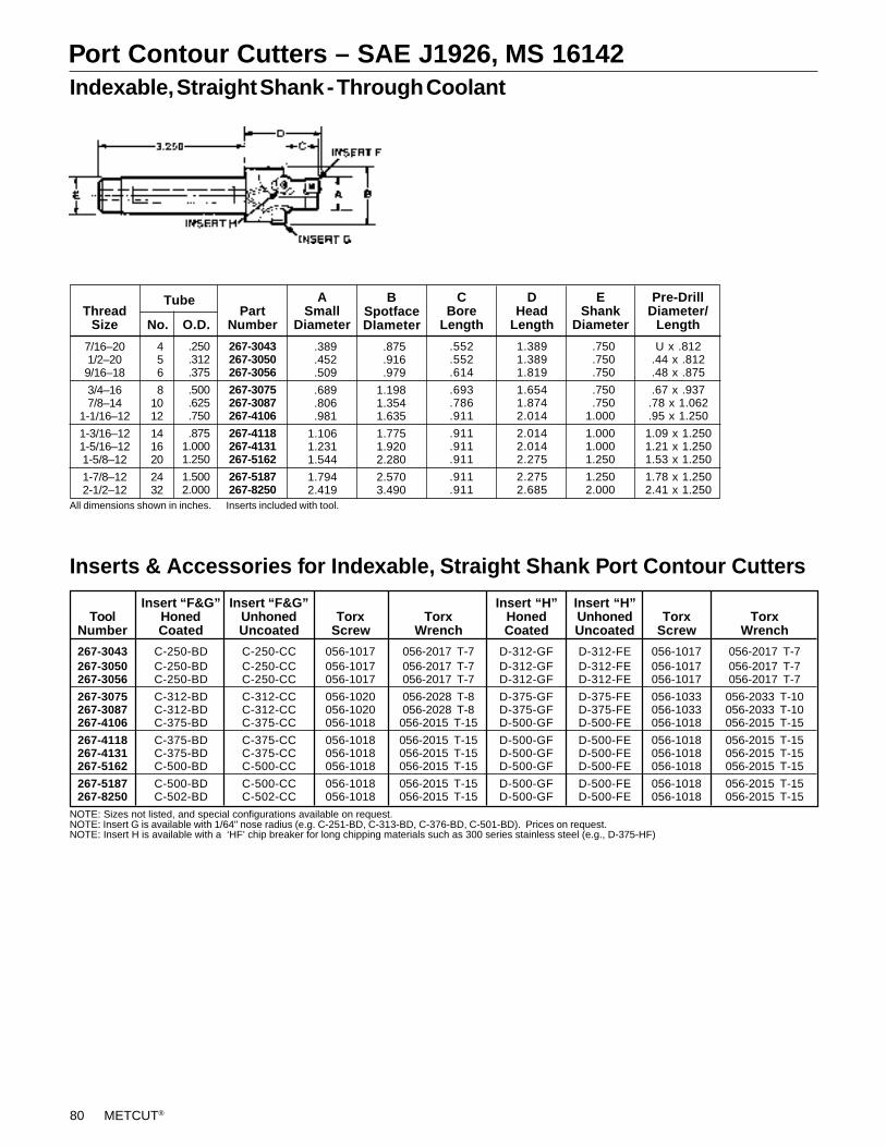
80 METCUT®
Port Contour Cutters – SAE J1926, MS 16142Indexable, Straight Shank - Through Coolant
Inserts & Accessories for Indexable, Straight Shank Port Contour Cutters
7/16–201/2–209/16–18
3/4–167/8–14
1-1/16–12
1-3/16–121-5/16–121-5/8–12
1-7/8–122-1/2–12
ThreadSize No. O.D.
456
81012
141620
2432
Tube
267-3043267-3050267-3056
267-3075267-3087267-4106
267-4118267-4131267-5162
267-5187267-8250
PartNumber
ASmall
Diameter
1.3891.3891.819
1.6541.8742.014
2.0142.0142.275
2.2752.685
.552
.552
.614
.693
.786
.911
.911
.911
.911
.911
.911
CBore
Length
EShank
Diameter
DHead
Length
BSpotfaceDIameter
Pre-DrillDiameter/
Length
All dimensions shown in inches. Inserts included with tool.
.250
.312
.375
.500
.625
.750
.8751.0001.250
1.5002.000
.389
.452
.509
.689
.806
.981
1.1061.2311.544
1.7942.419
.875
.916
.979
1.1981.3541.635
1.7751.9202.280
2.5703.490
.750
.750
.750
.750
.7501.000
1.0001.0001.250
1.2502.000
U x .812.44 x .812.48 x .875
.67 x .937.78 x 1.062.95 x 1.250
1.09 x 1.2501.21 x 1.2501.53 x 1.250
1.78 x 1.2502.41 x 1.250
NOTE: Sizes not listed, and special configurations available on request.NOTE: Insert G is available with 1/64" nose radius (e.g. C-251-BD, C-313-BD, C-376-BD, C-501-BD). Prices on request.NOTE: Insert H is available with a ‘HF’ chip breaker for long chipping materials such as 300 series stainless steel (e.g., D-375-HF)
Insert “F&G” Insert “F&G” Insert “H” Insert “H”Tool Honed Unhoned Torx Torx Honed Unhoned Torx Torx
Number Coated Uncoated Screw Wrench Coated Uncoated Screw Wrench
267-3043 C-250-BD C-250-CC 056-1017 056-2017 T-7 D-312-GF D-312-FE 056-1017 056-2017 T-7267-3050 C-250-BD C-250-CC 056-1017 056-2017 T-7 D-312-GF D-312-FE 056-1017 056-2017 T-7267-3056 C-250-BD C-250-CC 056-1017 056-2017 T-7 D-312-GF D-312-FE 056-1017 056-2017 T-7
267-3075 C-312-BD C-312-CC 056-1020 056-2028 T-8 D-375-GF D-375-FE 056-1033 056-2033 T-10267-3087 C-312-BD C-312-CC 056-1020 056-2028 T-8 D-375-GF D-375-FE 056-1033 056-2033 T-10267-4106 C-375-BD C-375-CC 056-1018 056-2015 T-15 D-500-GF D-500-FE 056-1018 056-2015 T-15
267-4118 C-375-BD C-375-CC 056-1018 056-2015 T-15 D-500-GF D-500-FE 056-1018 056-2015 T-15267-4131 C-375-BD C-375-CC 056-1018 056-2015 T-15 D-500-GF D-500-FE 056-1018 056-2015 T-15267-5162 C-500-BD C-500-CC 056-1018 056-2015 T-15 D-500-GF D-500-FE 056-1018 056-2015 T-15
267-5187 C-500-BD C-500-CC 056-1018 056-2015 T-15 D-500-GF D-500-FE 056-1018 056-2015 T-15267-8250 C-502-BD C-502-CC 056-1018 056-2015 T-15 D-500-GF D-500-FE 056-1018 056-2015 T-15
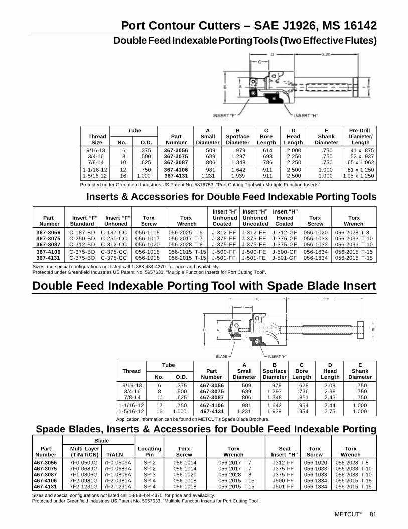
METCUT® 81
Port Contour Cutters – SAE J1926, MS 16142 Double Feed Indexable Porting Tools (Two Effective Flutes)
9/16-18 6 .375 367-3056 .509 .979 .614 2.000 .750 .41 x .875 3/4-16 8 .500 367-3075 .689 1.297 .693 2.250 .750 .53 x .937 7/8-14 10 .625 367-3087 .806 1.348 .786 2.250 .750 .65 x 1.0621-1/16-12 12 .750 367-4106 .981 1.642 .911 2.500 1.000 .81 x 1.2501-5/16-12 16 1.000 367-4131 1.231 1.939 .911 2.500 1.000 1.05 x 1.250
Tube A B C D E Pre-Drill Thread Part Small Spotface Bore Head Shank Diameter/ Size No. O.D. Number Diameter Diameter Length Length Diameter Length
Inserts & Accessories for Double Feed Indexable Porting Tools
367-3056 C-187-BD C-187-CC 056-1115 056-2025 T-5 J-312-FF J-312-FE J-312-GF 056-1020 056-2028 T-8367-3075 C-250-BD C-250-CC 056-1017 056-2017 T-7 J-375-FF J-375-FE J-375-GF 056-1033 056-2033 T-10367-3087 C-312-BD C-312-CC 056-1020 056-2028 T-8 J-375-FF J-375-FE J-375-GF 056-1033 056-2033 T-10367-4106 C-375-BD C-375-CC 056-1018 056-2015 T-15 J-500-FF J-500-FE J-500-GF 056-1834 056-2015 T-15367-4131 C-375-BD C-375-CC 056-1018 056-2015 T-15 J-501-FF J-501-FE J-501-GF 056-1834 056-2015 T-15
Insert “H” Insert “H” Insert “H” Part Insert “F” Insert “F” Torx Torx Unhoned Unhoned Honed Torx Torx Number Standard Unhoned Screw Wrench Coated Uncoated Coated Screw Wrench
Sizes and special configurations not listed call 1-888-434-4370 for price and availability.Protected under Greenfield Industries US Patent No. 5957633, "Multiple Function Inserts for Port Cutting Tool".
Protected under Greenfield Industries US Patent No. 5816753, "Port Cutting Tool with Multiple Function Inserts".
Double Feed Indexable Porting Tool with Spade Blade Insert
Tube A B C D E Thread Part Small Spotface Bore Head Shank
No. O.D. Number Diameter Diameter Length Length Diameter
9/16-18 6 .375 467-3056 .509 .979 .628 2.09 .750 3/4-16 8 .500 467-3075 .689 1.297 .736 2.38 .750 7/8-14 10 .625 467-3087 .806 1.348 .851 2.43 .750
1-1/16-12 12 .750 467-4106 .981 1.642 .954 2.44 1.0001-5/16-12 16 1.000 467-4131 1.231 1.939 .954 2.75 1.000
Spade Blades, Inserts & Accessories for Double Feed Indexable PortingApplication information can be found on METCUT's Spade Blade Brochure.
D 3.25
EB A
C
BLADE INSERT "H"
Sizes and special configurations not listed call 1-888-434-4370 for price and availability.Protected under Greenfield Industries US Patent No. 5957633, "Multiple Function Inserts for Port Cutting Tool".
Blade
Part Multi Layer Locating Torx Torx Seat Torx TorxNumber (TiN/TiCN) TiALN Pin Screw Wrench Insert “H” Screw Wrench
467-3056 7F0-0509G 7F0-0509A SP-2 056-1014 056-2017 T-7 J312-FF 056-1020 056-2028 T-8467-3075 7F0-0689G 7F0-0689A SP-2 056-1014 056-2017 T-7 J375-FF 056-1033 056-2033 T-10467-3087 7F1-0806G 7F1-0806A SP-3 056-1020 056-2028 T-8 J375-FF 056-1033 056-2033 T-10467-4106 7F2-0981G 7F2-0981A SP-4 056-1018 056-2015 T-15 J500-FF 056-1834 056-2015 T-15467-4131 7F2-1231G 7F2-1231A SP-4 056-1018 056-2015 T-15 J501-FF 056-1834 056-2015 T-15
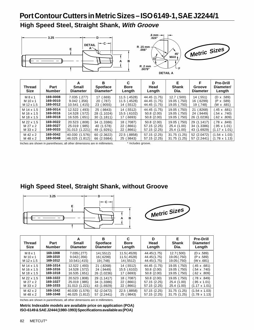
82 METCUT®
Port Contour Cutters in Metric Sizes – ISO 6149-1, SAE J2244/1High Speed Steel, Straight Shank, With Groove
14 (.551)16 (.6299)19 (.748)
21 (.8268)24 (.9449)26 (1.0236)
29 (1.1417)34 (1.3386)43 (1.6929)
52 (2.0472)57 (2.2441)
Pre-DrillDiameter/
Length
(D x .589)(P x .589)(W x .681)
(.45 x .681)(.54 x .740)(.62 x .809)
(.78 x .849)(.95 x 1.01)
(1.17 x 1.01)
(1.54 x 1.03)(1.78 x 1.13)
ASmall
Diameter
7.035 (.277)9.042 (.356)
10.541 (.415)
12.522 (.493)14.528 (.572)16.535 (.651)
20.523 (.808)25.019 (.985)
31.013 (1.221)
40.030 (1.576)46.025 (1.812)
PartNumber
169-0008169-0010169-0012
169-0014169-0016169-0018
169-0022169-0027169-0033
169-0042169-0048
M 8 x 1M 10 x 1
M 12 x 1.5
M 14 x 1.5M 16 x 1.5M 18 x 1.5
M 22 x 1.5M 27 x 2M 33 x 2
M 42 x 2M 48 x 2
ThreadSize
17 (.669)20 (.787)
23 (.9055)
25 (.9843)28 (1.1024)30 (1.1811)
34 (1.3386)40 (1.578)49 (1.9291)
60 (2.3622)66 (2.5984)
BSpotfaceDiameter*
CBore
Length
11.5 (.4528)11.5 (.4528)14 (.5512)
14 (.5512)15.5 (.6102)17 (.6693)
18 (.7087)22 (.8661)22 (.8661)
22.5 (.8858)25 (.9843)
44.45 (1.75)44.45 (1.75)44.45 (1.75)
44.45 (1.75)50.8 (2.00)50.8 (2.00)
50.8 (2.00)57.15 (2.25)57.15 (2.25)
57.15 (2.25)57.15 (2.25)
DHead
Length
EShank
Dia.
12.7 (.500)19.05 (.750)19.05 (.750)
19.05 (.750)19.05 (.750)19.05 (.750)
19.05 (.750)25.4 (1.00)25.4 (1.00)
31.75 (1.25)31.75 (1.25)
FGroove
Diameter
A B
C
D3.25
E
High Speed Steel, Straight Shank, without Groove
A B
C
D3.25
EDETAIL
A
DETAIL A
.6 mm.024"
R .15 mm.006"
R .2 mm.0079" F
45°15° MAX
Inches are shown in parentheses; all other dimensions are in millimeters. * Includes groove.
Metric Sizes
Metric Sizes
ASmall
Diameter
7.035 (.277)9.042 (.356)10.541 (.415)
12.522 (.493)14.528 (.572)16.535 (.651)
20.523 (.808)25.019 (.985)
31.013 (1.221)
40.030 (1.576)46.025 (1.812)
PartNumber
169-1008169-1010169-1012
169-1014169-1016169-1018
169-1022169-1027169-1033
169-1042169-1048
M 8 x 1M 10 x 1
M 12 x 1.5
M 14 x 1.5M 16 x 1.5M 18 x 1.5
M 22 x 1.5M 27 x 2M 33 x 2
M 42 x 2M 48 x 2
ThreadSize
14 (.5512)16 (.6299)19 (.748)
21 (.8268)24 (.9449)26 (1.0236)
29 (1.1417)34 (1.3386)43 (1.6929)
52 (2.0472)57 (2.2441)
BSpotfaceDiameter
CBore
Length
11.5 (.4528)11.5 (.4528)14 (.5512)
14 (.5512)15.5 (.6102)17 (.6693)
18 (.7087)22 (.8661)22 (.8661)
22.5 (.8858)25 (.9843)
44.45 (1.75)44.45 (1.75)44.45 (1.75)
44.45 (1.75)50.8 (2.00)50.8 (2.00)
50.8 (2.00)57.15 (2.25)57.15 (2.25)
57.15 (2.25)57.15 (2.25)
DHead
Length
EShank
Dia.
12.7 (.500)19.05 (.750)19.05 (.750)
19.05 (.750)19.05 (.750)19.05 (.750)
19.05 (.750)25.4 (1.00)25.4 (1.00)
31.75 (1.25)31.75 (1.25)
Pre-DrillDiameter/
Length
(D x .589)(P x .589)(W x .681)
(.45 x .681)(.54 x .740)(.62 x .809)
(.78 x .849)(.95 x 1.01)
(1.17 x 1.01)
(1.54 x 1.03)(1.78 x 1.13)
Inches are shown in parentheses; all other dimensions are in millimeters.
Metric Indexable models are available price on application (POA)ISO-6149 & SAE J2444 (1980-1993) Specifications available as (POA)
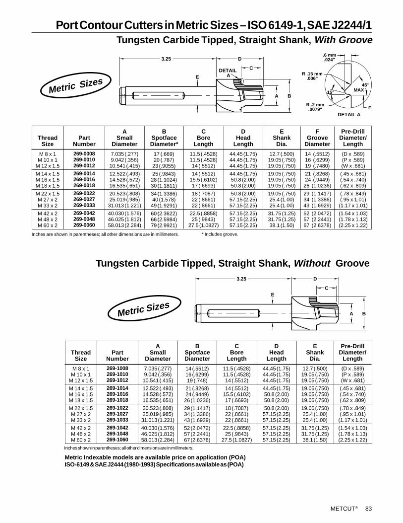
METCUT® 83
Port Contour Cutters in Metric Sizes – ISO 6149-1, SAE J2244/1Tungsten Carbide Tipped, Straight Shank, With Groove
14 (.5512)16 (.6299)19 (.7480)
21 (.8268)24 (.9449)
26 (1.0236)
29 (1.1417)34 (1.3386)43 (1.6929)
52 (2.0472)57 (2.2441)67 (2.6378)
Pre-DrillDiameter/
Length
(D x .589)(P x .589)(W x .681)
(.45 x .681)(.54 x .740)(.62 x .809)
(.78 x .849)(.95 x 1.01)(1.17 x 1.01)
(1.54 x 1.03)(1.78 x 1.13)(2.25 x 1.22)
ASmall
Diameter
7.035 (.277)9.042 (.356)10.541 (.415)
12.522 (.493)14.528 (.572)16.535 (.651)
20.523 (.808)25.019 (.985)31.013 (1.221)
40.030 (1.576)46.025 (1.812)58.013 (2.284)
PartNumber
269-0008269-0010269-0012
269-0014269-0016269-0018
269-0022269-0027269-0033
269-0042269-0048269-0060
M 8 x 1M 10 x 1
M 12 x 1.5
M 14 x 1.5M 16 x 1.5M 18 x 1.5
M 22 x 1.5M 27 x 2M 33 x 2
M 42 x 2M 48 x 2M 60 x 2
ThreadSize
Inches are shown in parentheses; all other dimensions are in millimeters. * Includes groove.
17 (.669)20 (.787)23 (.9055)
25 (.9843)28 (1.1024)30 (1.1811)
34 (1.3386)40 (1.578)49 (1.9291)
60 (2.3622)66 (2.5984)79 (2.9921)
BSpotfaceDiameter*
CBore
Length
11.5 (.4528)11.5 (.4528)14 (.5512)
14 (.5512)15.5 (.6102)17 (.6693)
18 (.7087)22 (.8661)22 (.8661)
22.5 (.8858)25 (.9843)
27.5 (1.0827)
44.45 (1.75)44.45 (1.75)44.45 (1.75)
44.45 (1.75)50.8 (2.00)50.8 (2.00)
50.8 (2.00)57.15 (2.25)57.15 (2.25)
57.15 (2.25)57.15 (2.25)57.15 (2.25)
DHead
Length
EShank
Dia.
12.7 (.500)19.05 (.750)19.05 (.750)
19.05 (.750)19.05 (.750)19.05 (.750)
19.05 (.750)25.4 (1.00)25.4 (1.00)
31.75 (1.25)31.75 (1.25)38.1 (1.50)
FGroove
Diameter
Tungsten Carbide Tipped, Straight Shank, Without Groove
A B
C
D3.25
E
A B
C
D3.25
EDETAIL
A
DETAIL A
R .2 mm.0079" F
45°MAX
.6 mm.024"
R .15 mm.006"
15°
Metric Sizes
ASmall
Diameter
7.035 (.277)9.042 (.356)10.541 (.415)
12.522 (.493)14.528 (.572)16.535 (.651)
20.523 (.808)25.019 (.985)31.013 (1.221)
40.030 (1.576)46.025 (1.812)58.013 (2.284)
PartNumber
269-1008269-1010269-1012
269-1014269-1016269-1018
269-1022269-1027269-1033
269-1042269-1048269-1060
M 8 x 1M 10 x 1
M 12 x 1.5
M 14 x 1.5M 16 x 1.5M 18 x 1.5
M 22 x 1.5M 27 x 2M 33 x 2
M 42 x 2M 48 x 2M 60 x 2
ThreadSize
Inches shown in parentheses; all other dimensions are in millimeters.
14 (.5512)16 (.6299)19 (.748)
21 (.8268)24 (.9449)26 (1.0236)
29 (1.1417)34 (1.3386)43 (1.6929)
52 (2.0472)57 (2.2441)67 (2.6378)
BSpotfaceDiameter
CBore
Length
11.5 (.4528)11.5 (.4528)14 (.5512)
14 (.5512)15.5 (.6102)17 (.6693)
18 (.7087)22 (.8661)22 (.8661)
22.5 (.8858)25 (.9843)
27.5 (1.0827)
44.45 (1.75)44.45 (1.75)44.45 (1.75)
44.45 (1.75)50.8 (2.00)50.8 (2.00)
50.8 (2.00)57.15 (2.25)57.15 (2.25)
57.15 (2.25)57.15 (2.25)57.15 (2.25)
DHead
Length
EShank
Dia.
12.7 (.500)19.05 (.750)19.05 (.750)
19.05 (.750)19.05 (.750)19.05 (.750)
19.05 (.750)25.4 (1.00)25.4 (1.00)
31.75 (1.25)31.75 (1.25)38.1 (1.50)
Pre-DrillDiameter/
Length
(D x .589)(P x .589)(W x .681)
(.45 x .681)(.54 x .740)(.62 x .809)
(.78 x .849)(.95 x 1.01)(1.17 x 1.01)
(1.54 x 1.03)(1.78 x 1.13)(2.25 x 1.22)
Metric Indexable models are available price on application (POA)ISO-6149 & SAE J2444 (1980-1993) Specifications available as (POA)
Metric Sizes
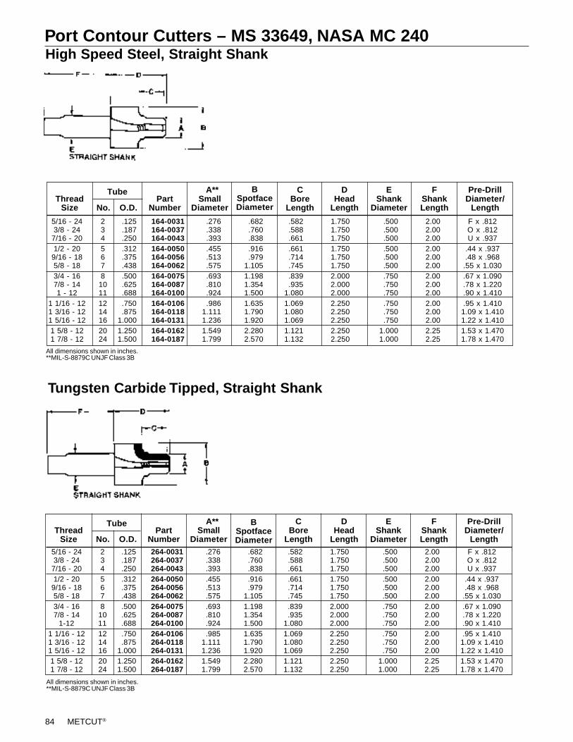
84 METCUT®
Port Contour Cutters – MS 33649, NASA MC 240High Speed Steel, Straight Shank
Tungsten Carbide Tipped, Straight Shank
All dimensions shown in inches.**MIL-S-8879C UNJF Class 3B
All dimensions shown in inches.**MIL-S-8879C UNJF Class 3B
Pre-DrillDiameter/
Length
FShankLength
EShank
Diameter
DHead
Length
CBore
Length
BSpotfaceDiameter
A**Small
DiameterPart
NumberNo. O.D.
TubeThread
Size
5/16 - 24 2 .125 164-0031 .276 .682 .582 1.750 .500 2.00 F x .8123/8 - 24 3 .187 164-0037 .338 .760 .588 1.750 .500 2.00 O x .812
7/16 - 20 4 .250 164-0043 .393 .838 .661 1.750 .500 2.00 U x .9371/2 - 20 5 .312 164-0050 .455 .916 .661 1.750 .500 2.00 .44 x .937
9/16 - 18 6 .375 164-0056 .513 .979 .714 1.750 .500 2.00 .48 x .9685/8 - 18 7 .438 164-0062 .575 1.105 .745 1.750 .500 2.00 .55 x 1.0303/4 - 16 8 .500 164-0075 .693 1.198 .839 2.000 .750 2.00 .67 x 1.0907/8 - 14 10 .625 164-0087 .810 1.354 .935 2.000 .750 2.00 .78 x 1.2201 - 12 11 .688 164-0100 .924 1.500 1.080 2.000 .750 2.00 .90 x 1.410
1 1/16 - 12 12 .750 164-0106 .986 1.635 1.069 2.250 .750 2.00 .95 x 1.4101 3/16 - 12 14 .875 164-0118 1.111 1.790 1.080 2.250 .750 2.00 1.09 x 1.4101 5/16 - 12 16 1.000 164-0131 1.236 1.920 1.069 2.250 .750 2.00 1.22 x 1.4101 5/8 - 12 20 1.250 164-0162 1.549 2.280 1.121 2.250 1.000 2.25 1.53 x 1.4701 7/8 - 12 24 1.500 164-0187 1.799 2.570 1.132 2.250 1.000 2.25 1.78 x 1.470
Pre-DrillDiameter/
Length
FShankLength
EShank
Diameter
DHead
Length
CBore
Length
BSpotfaceDiameter
A**Small
DiameterPart
NumberNo. O.D.
TubeThread
Size5/16 - 24 2 .125 264-0031 .276 .682 .582 1.750 .500 2.00 F x .8123/8 - 24 3 .187 264-0037 .338 .760 .588 1.750 .500 2.00 O x .812
7/16 - 20 4 .250 264-0043 .393 .838 .661 1.750 .500 2.00 U x .9371/2 - 20 5 .312 264-0050 .455 .916 .661 1.750 .500 2.00 .44 x .937
9/16 - 18 6 .375 264-0056 .513 .979 .714 1.750 .500 2.00 .48 x .9685/8 - 18 7 .438 264-0062 .575 1.105 .745 1.750 .500 2.00 .55 x 1.0303/4 - 16 8 .500 264-0075 .693 1.198 .839 2.000 .750 2.00 .67 x 1.0907/8 - 14 10 .625 264-0087 .810 1.354 .935 2.000 .750 2.00 .78 x 1.220
1-12 11 .688 264-0100 .924 1.500 1.080 2.000 .750 2.00 .90 x 1.4101 1/16 - 12 12 .750 264-0106 .985 1.635 1.069 2.250 .750 2.00 .95 x 1.4101 3/16 - 12 14 .875 264-0118 1.111 1.790 1.080 2.250 .750 2.00 1.09 x 1.4101 5/16 - 12 16 1.000 264-0131 1.236 1.920 1.069 2.250 .750 2.00 1.22 x 1.4101 5/8 - 12 20 1.250 264-0162 1.549 2.280 1.121 2.250 1.000 2.25 1.53 x 1.4701 7/8 - 12 24 1.500 264-0187 1.799 2.570 1.132 2.250 1.000 2.25 1.78 x 1.470
METCUT® 85
Port Contour Cutters – MS 33649, NASA MC 240Indexable, Straight Shank - Through Coolant
Inserts & Accessories for Indexable, Straight Shank Port Contour Cutters
7/16–201/2–209/16–18
3/4–167/8–14
1-1/16–12
1-3/16–121-5/16–121-5/8–12
1-7/8–122-1/4–12
ThreadSize No. O.D.
456
81012
141620
2428
Tube
268-3043 268-3050 268-3056
268-3075 268-3087 268-4106
*268-4118 268-4131 268-5162
*268-5187 268-8225
PartNumber
A**Small
Diameter
1.6871.6871.733
1.9492.0342.175
2.1752.1752.489
2.5002.614
CBore
Length
EShank
Diameter
DHead
Length
BSpotfaceDiameter
Pre-DrillDiameter/
Length
All dimensions shown in inches. Inserts included with tool.*Non-stocked.**MIL-S-8879C UNJF Class 3B
U x .937.44 x .93748 x .968
.67 x 1.090
.78 x 1.220
.95 x 1.410
1.09 x 1.4101.22 x 1.4101.53 x 1.470
1.78 x 1.4702.16 x 1.590
.750
.750
.750
.750
.7501.000
1.0001.0001.250
1.2502.000
.661
.661
.714
.839
.9351.069
1.0691.0691.121
1.1321.248
.875
.916
.979
1.1981.3541.635
1.7901.9202.280
2.5703.020
.393
.455
.513
.693
.810
.986
1.1111.2361.549
1.7992.174
.250
.312
.375
.500
.625
.750
.8751.0001.250
1.5001.750
NOTE: Sizes not listed, and special configurations available on request.NOTE: Insert G is available with 1/64" nose radius (e.g. C-251-BD, C-313-BD, C-376-BD, C-501-BD). Prices on request.
Insert “F&G” Insert “F&G” Insert “H” Insert “H”Tool Honed Unhoned Torx Torx Honed Unhoned Torx Torx
Number Coated Uncoated Screw Wrench Coated Uncoated Screw Wrench268-3043 C-250-BD C-250-CC 056-1017 056-2017 T-7 E-312-GF E-312-FE 056-1017 056-2017 T-7268-3050 C-250-BD C-250-CC 056-1017 056-2017 T-7 E-312-GF E-312-FE 056-1017 056-2017 T-7268-3056 C-250-BD C-250-CC 056-1017 056-2017 T-7 E-375-GF E-375-FE 056-1020 056-2028 T-8
268-3075 C-312-BD C-312-CC 056-1020 056-2028 T-8 E-376-GF E-376-FE 056-1020 056-2028 T-8268-3087 C-312-BD C-312-CC 056-1020 056-2028 T-8 E-377-GF E-377-FE 056-1020 056-2028 T-8268-4106 C-375-BD C-375-CC 056-1018 056-2015 T-15 E-378-GF E-378-FE 056-1018 056-2015 T-15
268-4118 C-375-BD C-375-CC 056-1018 056-2015 T-15 E-378-GF E-378-FE 056-1018 056-2015 T-15268-4131 C-375-BD C-375-CC 056-1018 056-2015 T-15 E-378-GF E-378-FE 056-1018 056-2015 T-15268-5162 C-500-BD C-500-CC 056-1018 056-2015 T-15 E-378-GF E-378-FE 056-1018 056-2015 T-15
268-5187 C-500-BD C-500-CC 056-1018 056-2015 T-15 E-378-GF E-378-FE 056-1018 056-2015 T-15268-8225 C-500-BD C-500-CC 056-1018 056-2015 T-15 E-378-GF E-378-FE 056-1018 056-2015 T-15
86 METCUT®
BSPP/BSPF (Rp) BSI BS21Tungsten Carbide Tipped, Straight Shank
A B C D E FThread Part Small Spotface Bore Head Shank Shank
Size Number Diameter Diameter Length Length Diameter Length1/8-28 265-2012 .346 .694 .625 1.750 .500 2.5001/4-19 265-2025 .465 .891 .830 1.750 .500 2.5003/8-19 265-2037 .600 1.009 .880 2.000 .500 2.500
1/2-14 265-3050 .748 1.186 1.066 2.250 .750 2.5003/4-14 265-3075 .964 1.452 1.066 2.250 .750 3.0001-11 265-3100 1.210 1.820 1.255 2.750 .750 3.000
1-1/4-11 265-4125 1.554 2.249 1.375 3.000 1.000 3.0001-1/2-11 265-4150 1.771 2.505 1.375 3.000 1.000 3.000
2-11 265-4200 2.249 3.000 1.567 3.250 1.000 3.0002-1/2-11 265-4250 2.874 3.500 1.849 3.500 1.000 3.250
Port Details
SAE J1926, MS 16142 & ISO 6149 (Metric) Port Detail
MS 33649, NASA MC 240 Port Detail
F
E
D
BA
C45°
C
.004/.008 R
METCUT® 87
Port Contour Cutters Application InformationSurface Feet Per Minute and Feet Per Revolution
AluminumCast IronMild Steel
Material
HSS Cutters
SFM* IPR**
.009–.012
.009–.012
.006–.009
2006050
* Based on Small Diameter. ** Based on 3-fluted tool. All feed and speeds based on uncoated tools.
AluminumCast IronMild Steel
Material
TCT Cutters
SFM* IPR**
.009–.012
.009–.012
.006–.009
400150140
Recommended Speeds and FeedsFor 267 and 268 Series Indexable Port Contour Cutters
The following speed and feed table should be used only as a starting point. Ultimate speedsand feeds depend upon the machine, the set-up, and material conditions
Note: All indexable tooling should be run on rigid spindle machines.
Part Mild Steel Cast Iron AluminumNumber Size RPM IPR RPM IPR RPM IPR
367-3056 9/16 – 18 2900–3100 .006–.010 2900–3100 .006–.010 4900–5100 .006–.010
367-3075 3/4 – 16 2100–2300 .006–.010 1900–2100 .008–.012 4900–5100 .006–.010
367-3087 7/8 – 14 1700–1900 .006–.010 1500–1700 .008–.012 4400–4600 .006–.010
367-4106 1 1/16 – 12 1500–1700 .008–.012 1300–1500 .010–.014 3700–3900 .008–.012
367-4118 1 3/16 – 12 1300–1500 .008–.012 1100–1300 .010–.014 3300–3500 .008–.012
For 367 Series Double Feed Indexable Porting Tools
For 467 Series Porting ToolsPlease refer to the above 367 series chart for specifying the feed only.
Please refer to the application chart in the Spade Blade Brochure for the speed only.
300 SeriesPart Mild Steel Stainless Steel Cast Iron Aluminum
Number Size RPM IPR RPM IPR RPM IPR RPM IPR267-3043 7/16 – 20 2900-3100 .003-.005 2600-2700 .003-.004 2900-3100 .003-.005 4900-5100 .003-.005268-3043
267-3050 1/2 – 20 2900-3100 .003-.005 2600-2700 .003-.004 2900-3100 .003-.005 4900-5100 .003-.005268-3050
267-3056 9/16 – 18 2900-3100 .003-.005 2600-2700 .003-.004 2900-3100 .003-.005 4900-5100 .003-.005268-3056
267-3075 3/4 – 16 2100-2300 .003-.005 1900-2000 .003-.004 1900-2100 .004-.006 4900-5100 .003-.005268-3075
267-3087 7/8 – 14 1700-1900 .003-.005 1500-1600 .003-.004 1500-1700 .004-.006 4400-4600 .003-.005268-3087
267-4106 1-1/16 – 12 1500-1700 .004-.006 1350-1450 .004-.005 1300-1500 .005-.007 3700-3900 .004-.006268-4106
267-4118 1-3/16 – 12 1300-1500 .004-.006 1150-1250 .004-.005 1100-1300 .005-.007 3300-3500 .004-.006268-4118
267-4131 1-5/16 – 12 1100-1300 .004-.006 1000-1100 .004-.005 900-1100 .005-.007 2900-3100 .004-.006268-4131
267-5162 1-5/8 – 12 900-1100 .005-.007 800-900 .005-.006 700-900 .006-.008 2400-2600 .005-.007268-5162
267-5187 1-7/8 – 12 700-900 .005-.007 600-700 .005-.006 500-700 .007-.009 1900-2100 .005-.007268-5187
267-8250 2-1/2 – 12 500-700 .005-.007 450-550 .005-.006 400-600 .007-.009 1500-1700 .005-.007268-8225
88 METCUT®
Pipe Tap CuttersRadial Drive, High Speed Steel, NPTF (Dry Seal) Or NPT
Straight Shank, High Speed Steel, NPTF (Dry Seal) Or NPT
Size
272718
181414
11-1/211-1/211-1/2
11-1/288
All dimensions shown in inches.
.06
.12
.25
.38
.50
.75
1.001.251.50
2.002.503.00
ThreadsperInch
186-3006186-3012186-3025
186-3037186-3050186-3075
186-6100186-6125186-6150
186-6200186-7250186-7300
PartNumber A
.94
.94
.94
.941.001.19
1.561.812.06
2.503.003.62
B±.002
.254
.346
.448
.586
.724
.935
1.1731.5171.756
2.2302.6663.292
C D
.56
.56
.78
.811.061.06
1.311.341.34
1.341.841.84
E
.03
.03
.03
.06
.06
.06
.12
.12
.12
.12
.12
.12
1.501.502.00
2.002.252.25
2.502.502.50
2.503.003.00
NMin. HoleDiameter
.177
.287
.357
.425
.548
.759
.7771.1211.358
1.4322.2372.863
RCRCRC
RCRCRC
RJRJRJ
RJRSRS
RadialDrive
Numberof
Flutes
333
333
334
444
Size
272718
181414
11-1/211-1/211-1/2
11-1/2
All dimensions shown in inches.
.06
.12
.25
.38
.50
.75
1.001.251.50
2.00
ThreadsperInch
187-3006187-3012187-3025
187-3037187-3050187-3075
187-6100187-6125187-6150
187-6200
PartNumber A
.94
.94
.94
.941.001.19
1.561.812.06
2.50
B±.002
.254
.346
.448
.586
.724
.935
1.1731.5171.756
2.230
C D
.56
.56
.78
.811.061.06
1.311.341.34
1.34
E
.03
.03
.03
.06
.06
.06
.12
.12
.12
.12
1.501.502.00
2.002.252.25
2.502.502.50
2.50
Numberof
Flutes
333
333
334
4
NMin. HoleDiameter
.177
.287
.357
.425
.548
.759
.7771.1211.358
1.432
F
.750
.750
.750
.750
.750
.750
1.0001.0001.000
1.250
E3.250
A C
D45°
N
B
F
.750 T.P.F.
E
A C
D45°
N
B
.750 T.P.F.
METCUT® 89
Core Drills; Spot & Chamfer Drills
Efficient, Economical Drilling ToolsMETCUT two-piece core drills are more economical than solidcore drills because the holder is used repeatedly— only thecutter end needs to be replaced.The drive features a square drive end on a short taper shank.The square eliminates all possibility of tang breakage or cornerrounding.METCUT two-piece core drill holders are available in long ormedium flute lengths with spiral flutes for effective chip dis-posal.Short holders without flutes are available in morse taper orstraight shanks. These holders are used where it is not neces-sary to guide-in a bushing.Spot and chamfer drills are available in a variety of sizes andtwo cutting angles.
90 METCUT®
Square Drive Core Drills
130-1150130-1162130-1175
130-2187130-2193130-2200
130-2206130-2212130-2218
130-3225130-3231130-3237
130-3243130-3250130-3256
130-4262130-4275130-4287
130-4293130-4300130-5312
130-5325130-5337130-5350
130-5375130-6400130-6425
130-6450130-6475130-6500
1.50001.62501.7500
1.87501.93752.0000
2.06252.12502.1875
2.25002.31252.3750
2.43752.50002.5625
2.62502.75002.8750
2.93753.00003.1250
3.25003.37503.5000
3.75004.00004.2500
4.50004.75005.0000
All dimensions shown in inches.*Non-stocked.
PartNumber
1.3751.3751.375
1.5001.5001.500
1.5001.5001.500
1.5001.5001.500
1.5001.5001.500
1.7501.7501.750
1.7501.7501.750
1.7501.7501.750
1.7502.0002.000
2.0002.0002.000
1.001.081.16
1.231.271.33
1.361.411.44
1.481.531.56
1.611.661.69
1.731.811.86
1.942.002.06
2.142.222.31
2.472.642.81
2.973.123.30
PartNumber
*330-1150*330-1162*330-1175
*330-2187*330-2193*330-2200
*330-2206*330-2212*330-2218
*330-3225*330-3231*330-3237
*330-3243*330-3250*330-3256
*330-4262*330-4275*330-4287
*330-4293*330-4300*330-5312
*330-5325*330-5337*330-5350
*330-5375*330-6400*330-6425
*330-6450*330-6475*330-6500
10.12510.75011.375
11.62511.75011.750
11.25011.25011.250
11.25011.25011.250
12.62512.62513.375
13.37514.25015.000
15.62515.62516.000
16.00016.50016.500
17.00017.50017.500
18.00018.00018.000
PartNumber
*331-1150*331-1162*331-1175
*331-2187*331-2193*331-2200
*331-2206*331-2212*331-2218
*331-3225*331-3231*331-3237
*331-3243*331-3250*331-3256
*331-4262*331-4275*331-4287
*331-4293*331-4300*331-5312
*331-5325*331-5337*331-5350
*331-5375*331-6400*331-6425
*331-6450*331-6475*331-6500
444
444
555
555
555
555
555
555
566
666
535353
616161
616161
717171
717171
878787
878792
929292
92112112
112112112
ADiameter
BHead
Length
CSmallEnd
EMorseTaperShank
FSquareDrive
Number
DBody
Lengthw/Cutter
DBody
Lengthw/Cutter
Short Fluted HoldersLong Fluted HoldersHigh Speed Steel Cutters
5.8756.1256.375
6.6256.7506.750
6.5006.5006.500
6.5006.5006.500
7.1257.1257.500
7.6258.0008.250
8.6258.6259.000
9.0009.5009.500
10.00010.50010.500
11.00011.00011.000
Square Drive Core Drill Screws
5361 & 71
87 & 92112
Bolt Size
054-1018054-2025
054-4031054-6031
PartNumber
SquareDrive No.
10–24 x 31/4–20 x 3
5/16–18 x 3-1/25/16–18 x 4-1/4
METCUT® 91
184-3037184-3050
184-3075184-3100
90°Included Angle
184-2037184-2050
184-2075184-2100
118°Included Angle
7.8007.800
7.8007.800
6.500—
——
B CA D
.031
.031
.063
.063
E
Part Numbers Dimensions
All dimensions shown in inches.
.375
.500
.7501.000
.500
.500
.7501.000
High Speed Steel
Spot and Chamfer DrillsIndexable
Carbide Grade Descriptions:
M A CVD tri-phase coated tough carbide grade for steels, stainless steel and high temp alloys (HM, BM inserts).
L A PVD coated micrograin carbide for cast iron, nonferrous metals, nonmetals, austenitic stainless steels and titanium (HL, BL inserts).NOTE: Inserts available in a ‘H’ grade - a PVD coated micrograin carbide for abrasive nonferrous alloys (HH, BH inserts). Prices on request.
A B C D Torx TorxPart Included Maximum Extension Overall Shank Effective Insert Screw Wrench
Number Angle Diameter Length Length Diameter Inserts Number Part No. Part No.284-0900 90° .625 1.50 3.50 .750 1 T-375-HM T-375-HL 056-1020 056-2028 T-8284-1200 120° .812 1.50 3.50 .750 1 S-500-BM S-500-BL 056-1834 056-2015 T-15
90° Included Angle
REF.
DIA.OVER INS.
A
B
C
D ANGLE
FLAT
120° Included Angle
FLAT
REF.
DIA.OVER INS.
A
BC
D ANGLE
92 METCUT®
Technical Reference
Fraction Inches mm
33/6417/32
35/649/16
37/6419/32
39/645/8
41/6421/32
43/6411/16
45/6423/32
47/643/4
49/6425/32
51/6413/16
53/6427/32
55/647/8
57/6429/32
59/6415/16
61/6431/32
63/641
.5156
.5313
.5469
.5625
.5781
.5938
.6094
.6250
.6406
.6563
.6719
.6875
.7031
.7188
.7344
.7500
.7656
.7813
.7969
.8125
.8281
.8438
.8594
.8750
.8906
.9063
.9219
.9375
.9531
.9688
.9844 1.0000
Decimal & Metric Equivalents
Fraction Inches1/64
1/323/64
1/165/64
3/327/64
1/89/64
5/3211/64
3/1613/64
7/3215/64
1/417/64
9/3219/64
5/1621/64
11/3223/64
3/825/64
13/3227/64
7/1629/64
15/3231/64
1/2
.0156
.0313
.0469
.0625
.0781
.0938
.1094
.1250
.1406
.1563
.1719
.1875
.2031
.2188
.2344
.2500
.2656
.2813
.2969
.3125
.3281
.3438
.3594
.3750
.3906
.4063
.4219
.4375
.4531
.4688
.4844
.5000
mm
0.3970.7941.1911.5881.9842.3812.7783.1753.5723.9794.3664.7635.1595.5565.9536.3506.7477.1447.5417.9388.3348.7319.1289.5259.922
10.31910.71611.11311.50911.90612.30312.700
13.09713.49413.89114.28814.68415.08115.47815.87516.27216.66917.06617.46317.85918.25618.65319.05019.44719.84420.24120.63821.03421.43121.83822.22522.62223.01923.41623.81323.85224.60625.00325.400
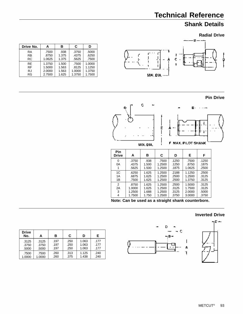
METCUT® 93
Radial Drive
Technical ReferenceShank Details
Pin Drive
Inverted Drive
Drive No.RARBRC
RERFRJRS
.7500
.87501.0625
1.37501.50002.00002.7500
A B.3750.4375.5625
.7500
.81251.00001.3750
.9381.3751.375
1.5001.5631.5631.625
C.5000.6250.7500
1.00001.12501.37501.7500
D
PinDrive
00A1
1C1A1B
22A34
D.1250.1250.1875
.2188
.2500
.2500
.2500
.3125
.3125
.3750
F.1250.1875.2500
.2500
.3125
.3125
.3125
.3125
.5000
.3750
.3750
.4375
.5625
.6250
.6875
.7500
.87501.00001.25001.7500
.9381.5001.500
1.6251.6251.625
1.6251.6251.6881.750
.75001.25001.2500
1.25001.25001.2500
1.25001.25001.25001.2500
A B C.7500.8750
1.0625
1.12501.25001.3750
1.50001.75002.00003.0000
E
Note: Can be used as a straight shank counterbore.
B.197.197.197
.260
.260
C.250.250.250
.313
.375
D1.0631.0631.063
1.1251.438
E.177.177.177
.240
.240
.3125
.3750
.5000
.75001.0000
.3125
.3750
.5000
.75001.0000
ADriveNo.
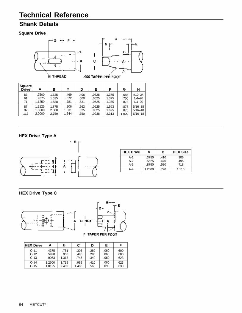
94 METCUT®
Technical ReferenceShank Details
HEX Drive Type A
HEX Drive Type C
Square Drive
D.406.500.531
.563
.625
.750
E.0625.0625.0625
.0625
.0625
.0938
F1.3751.3751.375
1.5631.6252.313
H#10–241/4–201/4–20
5/16–185/16–185/16–18
B1.6251.6251.688
1.8752.0002.750
SquareDrive
536171
8792112
.688
.750
.875
.875
.8751.000
G.469.672.781
.9061.0311.344
C
.7500
.93751.1250
1.31251.50002.0000
A
B.410.470.530
.720
.3750
.5625
.8750
1.2500
A HEX Size.306.495.718
1.110
HEX DriveA-1A-2A-3
A-4
D.280.280.340
.410
.560
E.060.060.060
.060
.090
HEX DriveC-11C-12C-13
C-14C-15
F.600.600.623
.623
.630
.306
.495
.745
.9881.488
C.781.906
1.313
1.7192.469
B
.4375
.5938
.9063
1.25001.8125
A
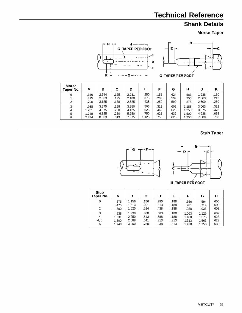
METCUT® 95
Technical ReferenceShank Details
Morse Taper
Stub Taper
B2.3442.5633.125
3.8754.8756.1258.563
K.160.213.260
.322
.478
.635
.760
MorseTaper No.
012
3456
C.125.125.188
.188
.250
.250
.313
D2.0312.1882.625
3.2504.1255.2507.375
F.156.203.250
.313
.469
.625
.750
G.624.599.599
.602
.623
.632
.626
J1.9382.0632.500
3.0633.8754.9387.000
.356
.475
.700
.9381.2311.7482.494
A
.250
.375
.438
.563
.625
.7501.125
E
.563
.750
.875
1.1881.2501.5001.750
H
C.156.201.294
.388
.513
.641
.750
D.250.313.438
.563
.688
.813
.938
E.188.188.188
.188
.188
.313
.313
H.600.600.602
.602
.623
.623
.630
B1.1561.3131.625
1.9382.2502.6883.000
StubTaper No.
012
34
4, 55
.594
.719
.938
1.1251.3751.5631.750
G
.656
.781
.938
1.0631.1881.3131.438
F
.375
.475
.700
.9381.2311.5001.748
A

96 METCUT®
Modern metalcutting operations involve high energy, high spindle or cutter speeds, and hightemperatures and cutting forces. Hot, flying chips may be projected from the workpiece duringmetalcutting. Although advanced cutting tool materials are designed and manufactured to with-stand the high cutting forces and temperatures that normally occur in these operations, they aresusceptible to fragmenting in service, particularly if they are subjected to over-stress, severeimpact or otherwise abused. Therefore, precautions should be taken to adequately protectworkers, observers and equipment against hot, flying chips, fragmented cutting tools, brokenworkpieces or other similar projectiles. Machines should be fully guarded and personal protec-tive equipment should be used at all times.
When grinding advanced cutting tool materials, a suitable means for collection and disposal ofdust, mist or sludge should be provided. Overexposure to dust or mist containing metallic par-ticles can be hazardous to health particularly if exposure continues over an extended period oftime and may cause eye, skin and mucous membrane irritation and temporary or permanentrespiratory disease. Certain existing pulmonary and skin conditions may be aggravated byexposure to dust or mist. Adequate ventilation, respiratory protection and eye protection shouldbe provided when grinding and workers should avoid breathing of and prolonged skin contactwith dust or mist. General Industry Safety and Health Regulations, Part 1910. U.S. Departmentof Labor, published in Title 29 of the Code of Federal Regulations should be consulted. Obtainfrom METCUT and read the applicable Material Safety Data Sheet before grinding.
Cutting tools are only one part of the worker-machine-tool system. Many variables exist inmachining operations, including the metal removal rate; the workpiece size, shape, strength andrigidity; the chucking and fixturing; the load carrying capability of centers; the cutter and spindlespeed and torque limitations; the holder and boring bar overhang; the available power; and thecondition of the tooling and the machine. A safe metalcutting operation must take all of thesevariables, and others, into consideration.
METCUT has no control over the end use of its products or the environment into which thoseproducts are placed. METCUT urges that its customers adhere to the recommended standardsof use of their metalcutting machines and tools, and that they follow procedures that ensure safemetalcutting operations. The information included throughout this catalog under the heading“Technical Data” and other recommendations on machining practices referred to herein are onlyadvisory in nature and do not constitute representations or warranties and are not necessarilyappropriate for any particular work environment or application.
Metalcutting SafetyPlease read this before using METCUT ® products
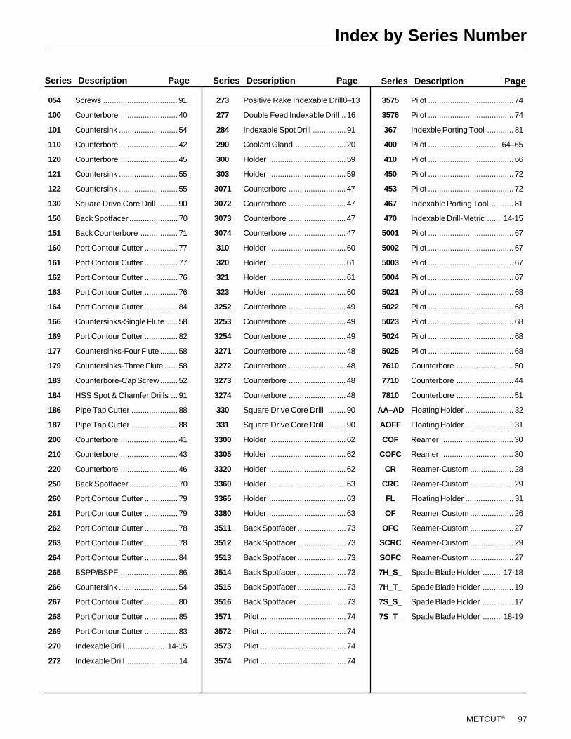
METCUT® 97
Index by Series Number
Series Description Page Series Description Page
273 Positive Rake Indexable Drill8–13
277 Double Feed Indexable Drill .. 16
284 Indexable Spot Drill ............... 91
290 Coolant Gland ....................... 20
300 Holder ................................... 59
303 Holder ................................... 59
3071 Counterbore .......................... 47
3072 Counterbore .......................... 47
3073 Counterbore .......................... 47
3074 Counterbore .......................... 47
310 Holder ................................... 60
320 Holder ................................... 61
321 Holder ................................... 61
323 Holder ................................... 60
3252 Counterbore .......................... 49
3253 Counterbore .......................... 49
3254 Counterbore .......................... 49
3271 Counterbore .......................... 48
3272 Counterbore .......................... 48
3273 Counterbore .......................... 48
3274 Counterbore .......................... 48
330 Square Drive Core Drill ......... 90
331 Square Drive Core Drill ......... 90
3300 Holder ................................... 62
3305 Holder ................................... 62
3320 Holder ................................... 62
3360 Holder ................................... 63
3365 Holder ................................... 63
3380 Holder ................................... 63
3511 Back Spotfacer ...................... 73
3512 Back Spotfacer ...................... 73
3513 Back Spotfacer ...................... 73
3514 Back Spotfacer ...................... 73
3515 Back Spotfacer ...................... 73
3516 Back Spotfacer ...................... 73
3571 Pilot ....................................... 74
3572 Pilot ....................................... 74
3573 Pilot ....................................... 74
3574 Pilot ....................................... 74
Series Description Page
3575 Pilot ....................................... 74
3576 Pilot ....................................... 74
367 Indexble Porting Tool ............ 81
400 Pilot ................................. 64–65
410 Pilot ....................................... 66
450 Pilot ....................................... 72
453 Pilot ....................................... 72
467 Indexable Porting Tool .......... 81
470 Indexable Drill-Metric ...... 14-15
5001 Pilot ....................................... 67
5002 Pilot ....................................... 67
5003 Pilot ....................................... 67
5004 Pilot ....................................... 67
5021 Pilot ....................................... 68
5022 Pilot ....................................... 68
5023 Pilot ....................................... 68
5024 Pilot ....................................... 68
5025 Pilot ....................................... 68
7610 Counterbore .......................... 50
7710 Counterbore .......................... 44
7810 Counterbore .......................... 51
AA–AD Floating Holder ...................... 32
AOFF Floating Holder ...................... 31
COF Reamer ................................. 30
COFC Reamer ................................. 30
CR Reamer-Custom .................... 28
CRC Reamer-Custom .................... 29
FL Floating Holder ...................... 31
OF Reamer-Custom .................... 26
OFC Reamer-Custom .................... 27
SCRC Reamer-Custom .................... 29
SOFC Reamer-Custom .................... 27
7H_S_ Spade Blade Holder ........ 17-18
7H_T_ Spade Blade Holder .............. 19
7S_S_ Spade Blade Holder .............. 17
7S_T_ Spade Blade Holder ........ 18-19
054 Screws .................................. 91
100 Counterbore .......................... 40
101 Countersink ........................... 54
110 Counterbore .......................... 42
120 Counterbore .......................... 45
121 Countersink ........................... 55
122 Countersink ........................... 55
130 Square Drive Core Drill ......... 90
150 Back Spotfacer ...................... 70
151 Back Counterbore ................. 71
160 Port Contour Cutter ............... 77
161 Port Contour Cutter ............... 77
162 Port Contour Cutter ............... 76
163 Port Contour Cutter ............... 76
164 Port Contour Cutter ............... 84
166 Countersinks-Single Flute ..... 58
169 Port Contour Cutter ............... 82
177 Countersinks-Four Flute ........ 58
179 Countersinks-Three Flute ...... 58
183 Counterbore-Cap Screw ........ 52
184 HSS Spot & Chamfer Drills ... 91
186 Pipe Tap Cutter ..................... 88
187 Pipe Tap Cutter ..................... 88
200 Counterbore .......................... 41
210 Counterbore .......................... 43
220 Counterbore .......................... 46
250 Back Spotfacer ...................... 70
260 Port Contour Cutter ............... 79
261 Port Contour Cutter ............... 79
262 Port Contour Cutter ............... 78
263 Port Contour Cutter ............... 78
264 Port Contour Cutter ............... 84
265 BSPP/BSPF .......................... 86
266 Countersink ........................... 54
267 Port Contour Cutter ............... 80
268 Port Contour Cutter ............... 85
269 Port Contour Cutter ............... 83
270 Indexable Drill ................. 14-15
272 Indexable Drill ....................... 14