indian railway standard code of practice …iricen.gov.in/iricen/bridge_manuals/steel bridge...
TRANSCRIPT
For Official use only
GOVERNMENT OF INDIA MINISTRY OF RAILWAYS
(Railway Board)
INDIAN RAILWAY STANDARD
INDIAN RAILWAY STANDARD CODE OF PRACTICE FOR THE DESIGN OF STEEL OR
WROUGHT IRON BRIDGES CARRYING RAIL, ROAD OR PEDESTRIAN TRAFFIC
(STEEL BRIDGE CODE)
ADOPTED –1941 INCORPORATING A & C SLIP NO. 17, YEAR : 2003
ISSUED BY RESEARCH DESIGNS AND STANDARDS ORGANISATION
LUCKNOW-226011
IVA-i
& CS-18, 19 & 20 YEAR 2014 &15 DISCLAIMER: THIS COMPILATION IS FOR REFERENCE ONLY,
FOR DETAILS REFER ORIGIANAL CORRECTION SLIPS
CONTENTS PAGE
1. SCOPE … 1
2. MATERIALS AND WORKMANSHIP … 2
3. LOADS, FORCES AND STRESSES … 3
3.1 Loads and Forces to be taken into account … 3
3.2 Combination of Loads and Forces … 3
3.3 Primary and Secondary Stresses … 3
3.4 Relief of Stresses … 4
3.5 Allowable Working Stresses for combinations of Loads and Forces … 4
3.6 Fluctuations of Stress (fatigue) … 6
3.7 Permissible Stresses … 7
3.8 Allowable Working Stresses for Parts in Axial Compression. … 7
3.9 Allowable Working Stresses in Bending … 13
3.10 Allowable Shear Stress in Solid Webs of Plate Girders … 20
3.11 Combined Stresses … 20
3.12 Allowable Working Loads on Cylindrical Roller and Spherical Expansion Bearings … 21
3.13 Allowable Working Pressure on Sliding Bearings. … 21
3.14 Basic Permissible Stresses for Cast Steel in Bearings … 21
3.15 Cast Iron … 21
3.16 Allowable Working Pressure under Bearings or Bed Plates … 22
3.17 Slab Bases for Bearings … 22
3.18 Basic permissible Stresses in Wrought Iron and Mild Steel of Early Manufacture. … 22
3.19 Special Notes on Working Stresses … 22
3.20 Existing Bridges … 23
IVA-ii

4. DESIGN AND CONSTRUCTION – GENERAL … 23
4.1 Effective Spans … 23
4.2 Effective Length of Struts … 23
4.3 Sectional Area … 24
4.4 Symmetry of Sections … 25
4.5 Minimum Sections … 25
4.6 Spacing and Depth of Girders … 26
4.7 Provision for Temperature, Stress and Deflection … 26
4.8 Anchorage … 26
4.9 Track Structures … 26
4.10 Clevises and Turnbuckles … 26
4.11 Composite Action of Steel and Concrete … 27
4.12 Composite Use of Mild Steel and High Tensile Steel … 27
4.13 Composite Connections … 27
4.14 End Cross Members … 27
4.15 General Provision Against Corrosion … 27
4.16 Camber … 27
4.17 Deflection … 27
5. SOLID WEB GIDERS … 27
5.1 Plate Girders and Rolled Beams … 28
5.2 Effective Sectional Area … 28
5.3 Slenderness Ratio … 28
5.4 Effective Length of Compression Flanges … 29
5.5 Flanges … 31
5.6 Connection of Flanges to Web … 32
IVA-iii

5.7 Curtailment of Flange Plates … 32
5.8 Web Thickness … 32
5.9 Web Edges … 32
5.10 Web Stiffeners … 32
5.11 Flange Splices … 34
5.12 Splices in Web … 35
5.13 Lateral Bracing … 35
6. OPEN WEB GIRDERS … 35
6.1 Intersection at Joints … 35
6.2 General Requirements for Compression Members … 35
6.3 Effective Length of Compression Members other than lacings … 37
6.4 Compression Members Composed of Two Components Back-to-Back 38
6.5 Lacing of Compression Members … 39
6.6 Battening of Compression Members … 40
6.7 General Requirements for Tension Members … 42
6.8 Tension Members Composed of Two Components Back-to-Back … 42
6.9 Lacing of Tension Members … 42
6.10 Battening of Tension Members … 43
6.11 Splices … 44
6.12 Connection at Intersections … 45
6.13 Lug Angles … 45
6.14 Section at pin Holes in Tension Members … 45
6.15 Pin Plates … 45
6.16 Diaphragms in Members … 46
6.17 Lateral Bracing … 46
IVA-iv

6.18 Sway Bracing … 46
6.19 Portal Bracing … 46
7. RIVETING, BOLTING AND WELDING … 46
7.1 Effective Diameter and Bearing Area of Rivets, Bolts and Pins … 46
7.2 Deductions for Holes for Rivets, Bolts and Pins … 46
7.3 Minimum Pitch of Rivets and Bolts … 47
7.4 Maximum Pitch of Rivets and Bolts … 47
7.5 Edge Distance … 47
7.6 Hand Driven Rivets … 47
7.7 Rivets or Bolts Through Packing … 47
7.8 Long Grip Rivets … 47
7.9 Rivets in Tension … 48
7.10 Bolts … 48
7.11 General Requirements for Welds … 48
IVA-v
APPENDICES
PAGE
Appendix A … Rules for prestressing open web girder spans … 49
Appendix B … Curves showing allowable working stresses Pac on effective cross section for axial compression. … 51
Appendix C … Critical Compression stress Cs for sections symmetrical about the x-x-axis-formula … 52
Appendix D … Method of computing permissible stresses in existing wrought iron or early steel girders. … 53
Appendix E … Method of Computing stresses in rivets at the ends of existing plate girders … 55
Appendix G … Values of allowable stress ‘P’ and number of repetitions of stress cycles ‘N’ for different classes of constructional details ( class A to Class G) … 56-72
Appendix H … Distribution of wheel loads on Steel Troughing or beams spanning transversely to the track. … 75
Appendix J … Recommendations for the design of Combined Road-Rail Bridges … 76-78
TABLES
Table I … Total variation in allowable stresses. … 5
Table II … Basic permissible stresses in structural steel … 7
Table III … Values of ‘P’ for various values of fy, the yield stress for mild steel and high tensile steel. … 11
Table-IV … Allowable working stresses Pac in kg/sq mm on effective cross section for axial compression … 11
Table-IV (a) … Allowable working stresses Pac in ton/sq in on effective cross section for axial compression. … 12
Table-V … Values of k1 … 13
Table-VI … Values of k2 … 14
Table-VII … Values of A and B to be used for calculating values of Cs in kg/sq mm … 15
IVA-vi

Table-VII (a) … Values of A and B to be used for calculating values of Cs in ton/sq in … 17
Table VIII … Allowable working stress Pbc for different values of critical stress Cs … 19
Table IX … The maximum permissible values of the equivalent stress fc for mild and high tensile steel … 20
Table XI … Effective length of compression members. … 36
***
IVA-vii

INDIAN RAILWAY STANDARD
CODE OF PRACTICE FOR THE DESIGN OF STEEL OR WROUGHT IRON BRIDGES
CARRYING RAIL, ROAD OR PEDESTRIAN TRAFFIC
(Steel Bridge Code)
1. SCOPE 1.1 This code is primarily intended to apply to the superstructure of simply supported steel bridges of spans up to 100 m (325 ft) between centres of bearings. Where appropriate, the provisions of the code may be adopted for larger spans or other types of steel bridges, but care should be taken, in these circumstances to make whatever amendments are necessary for fixity at the supports, continuity and other indeterminate or special conditions. 1.2 Where bridges of the through or semi-through type are adopted, they must be designed to allow for clearances specified in the appropriate schedule of dimensions, for different gauges in the case of Railway bridges or bridges over Railway, and in the case of road bridges clearances as specified by the appropriate authorities. 1.3 For road-bridges the design and construction shall comply with the Standard Specifications and Code of Practice for Road-bridges issued by the Indian Roads Congress. 1.4 Any revision or addition or deletion of the provisions of this code shall be issued only through the correction slip to this code. No cognizance shall be given to any policy directives issued through other means.
Note:- Unless otherwise specified the word ‘span’ shall mean effective span. 1. Where FPS equivalent are given the figures in the metric units are to be regarded as the standard. The FPS conversions are approximate. More accurate conversions should be based on IS: 786. 2. Attention is drawn to the fact that equations in the text, for which no units are specified, are applicable in any system of units, metric or FPS, provided the unit of length and the unit of force used in an equation are the same throughout. 2. MATERIALS AND WORKMANSHIP 2.1 Materials and workmanship, including protection against atmospheric corrosion, shall comply with the Indian Railway Standard Specifications B-1, B-2 and B-6 and other specifications mentioned therein. 2.2 This code makes reference to the following standards:- Indian Railway Standard Codes and Specifications Welded Bridge Code – 1972 B-1 Steel girder bridges B-2 Erection and riveting of bridge girders B-6 The manufacture of locomotive turn- tables M-2 Steel castings
IVA-1

Indian standards Amendments No.
210-1962 Specification for grey iron casting 1 & 2
226-1969 Specification for structural steel (standard quality) 1 & 2
786-1967 Conversion factors and conversion tables --
961-1962 Specification for structural steel (high tensile) 1 & 2
1148-1964 Specification for rivet bars for structural purposes.(Revised) 1
1149-1964 Specification for high tensile rivet bars for structural purposes ---
1367-1967 Technical supply condition for threaded fasteners. ---
1458-1965 Specification for Railway Bronze ingots and castings 1 to 4
1875-1971 Specification for carbon steel billets, blooms, slabs and bars for forgings subject to the following stipulations:-
(i) Both chemical composition and mechanical properties to comply with specification requirements. (ii) The maximum limits of sulphur and phosphorus are restricted to 0.040% each for class 3 and 4 steels. and (iii) Bend test requirements to be met as per specification.
2004-1970 Specification for carbon steel forgings for general engineering --- purposes with the additional stipulation of Bend Test to be carried out as per clause 8.2 of the specification.
2062-1969 Specification for Structural steel (fusion welding quality). ---
IS:4000-1992 High Strength Bolts In Steel Structures - Code Of Practice. (CS 19 dtd 2.1.14)
NOTE: Reference to Indian Standards, wherever appearing in this Code, shall mean the particular edition with amendments as indicated in this clause.
IVA-2

3. LOADS, FORCES AND STRESSES 3.1 Loads and Forces to be Taken into Account- For the purpose of computing stresses, the following items shall, where applicable be taken into account in accordance with the requirements specified in the Bridge Rules:- (a) Dead load. (b) Live load. (c) Impact effect. (d) Forces due to curvature and
eccentricity of Track. (e) Temperature effect. (f) Resistance of expansion bearings to
movements (g) Longitudinal force. (h) Racking force. (j) Forces on parapets. (k) Wind pressure effect. (l) Forces and effects due to earthquake. (m) Erection forces and effects. (n) Derailment loads. Subject to the provisions of other clauses, all forces shall be considered as applied and all loaded lengths chosen in such a way that the most adverse effect is caused on the member under consideration. 3.2 Combination of Loads and Forces- The following combination of forces shall be considered. 3.2.1 The worst combination possible of dead load with live load, impact effect and forces due to curvature and eccentricity of track. When considering the member whose primary function is to resist longitudinal and racking forces due to live load, the term live load shall include these forces. 3.2.2 In case of bridges situated in seismic zones I to III as given in Bridge Rules, only bridges of overall length more than 60 m or individual span more than 15 m for the worst possible combination of any or all the items ‘a’ to ‘j’ & ‘k’ or ‘l’ listed in clause 3.1
3.2.3 In cases of bridges situated in seismic zone IV & V as given in Bridge Rules, the worst combination possible of any or all the items ‘a’ to ‘j’ and ‘k’ or ‘l’ listed in clause 3.1 3.2.4 The worst combination possible of loads and forces during erection. 3.2.5 In case of ballasted deck bridges, the combination of dead load and derailment load shall be considered as an occasional load. 3.3 Primary and Secondary Stresses 3.3.1 Primary Stress- The primary stresses in the design of triangulated structures are defined as axial stresses in members calculated on the assumption that all members are straight and free to rotate at the joints; all joints lie at the intersection of the centroidal axes of the members; all loads, including the weight of the members are applied at the joints. 3.3.2. Secondary Stresses- In practice the assumptions made in clause 3.3.1 are not realized and consequently members are subjected not only to axial stress, but also to bending and shear stresses. These stresses are defined as secondary stresses, and fall into two groups. (a) Stresses which are the result of eccentricity of connections and of off-joint loading generally (e.g. load rolling direct on chords, self-weight of members and wind loads on members). (b) Stresses, which are the result of elastic deformation of the structure and the rigidity of the joints. These are known as deformation stresses. 3.3.3. Structures shall be designed, fabricated and erected in such a manner as to minimise as far as possible secondary stresses. In the case of truss spans, ratios of width of the members (in the plane of
IVA-3

distortion) to their lengths between centres of inter-sections may preferably be not greater than 1/12 for chord members and 1/24 for web members, in order to minimize the deformation stresses. 3.3.4. Secondary stresses which are the result of eccentricity of connections and off-joint loading generally (see clause 3.3.2(a)) shall be computed and combined with the co-existent axial stresses in accordance with clause 3.11.1, but secondary stresses due to the self-weight and wind on the member shall be ignored in this case. Note:- In computing the secondary stress due to loads being carried direct by a chord, the chord may be assumed to be a continuous girder supported at the panel points, the resulting bending moments, both at the centre and at the supports being taken as equal to ¾ of the maximum bending moment in a simply supported beam of span equal to the panel length. Where desired, calculations may be made and the calculated bending moments may be taken. In computing such bending moments, the impact allowance shall be based on a loaded length equal to one panel length. 3.3.5. In all cases of truss members deformation stresses described under clause 3.3.2(b) shall be either computed or assumed in accordance with clause 3.3.6 and added to the co-existing axial stresses. 3.3.6. In non-pre-stressed girders, deformation stresses mentioned under clause 3.3.2 (b) shall in the absence of calculation, be assumed to be not less than 16 2/3 per cent of the dead load and live load stress including impact. 3.3.7. In the case of pre-stressed girders, deformation stresses may be ignored. Girders shall not be designed for prestressing unless it is assured that the
standard of workmanship in the fabrication and erection of girders will be such that correct prestressing can be relied on. When this is not the case, alternative of partial prestressing, i.e complete prestressing of chords with no or partial prestressing of web members, may be considered and the girder designed accordingly. 3.3.8. The effectiveness of prestressing in the web members of spans below 60m (200ft) and in all members of spans below 45m (150ft) shall be ignored. 3.3.9. All open web girders for railway bridges of spans 30.5 m (100ft) and above shall be prestressed. Rules for prestressing are given in APPENDIX-A. 3.4 Relief of Stresses- In determining the maximum stress in any member of a bridge, it is permissible to take into account any relief afforded to the member by adjoining parts. In determining the amount of relief, the secondary stresses, if any in the member shall be taken into account and considered with other co-existent stresses. Such relief may be taken into account only if the relieving parts have been suitably designed and are effectively attached to the member. In every such case it is necessary to consider whether the relief considered will be given by the adjacent member permanently or is liable to vanish owing to any change in the said adjacent member. 3.5 Allowable working stresses for Combinations of Loads and Forces 3.5.1 For the forces of combination 3.2.1 above, the allowable working stresses shall be those stresses given in clauses 3.7 to 3.18 inclusive. Where secondary stresses are taken into account, the allowable working stresses may be increased by 162/3 per cent.
IVA-4
Increase of allowable stresses for stress combinations as per clauses Type of Girder
3.2.1 3.2.2 & 3.2.3 3.2.4 (a) Solid Web Girder For calculated primary stress
No increase
16 2/3%
25%
(b)Triangulated Trusses - (i) for calculated primary stress (ii) where primary stresses are combined with calculated secondary stresses of sub clause 3.3.2 (a) ( self wt. and wind on member ignored) and with deformation stresses of sub clause 3.3.2 (b)
No increase
16 2/3 %
16 2/3% 33 1/3%
25% 40%
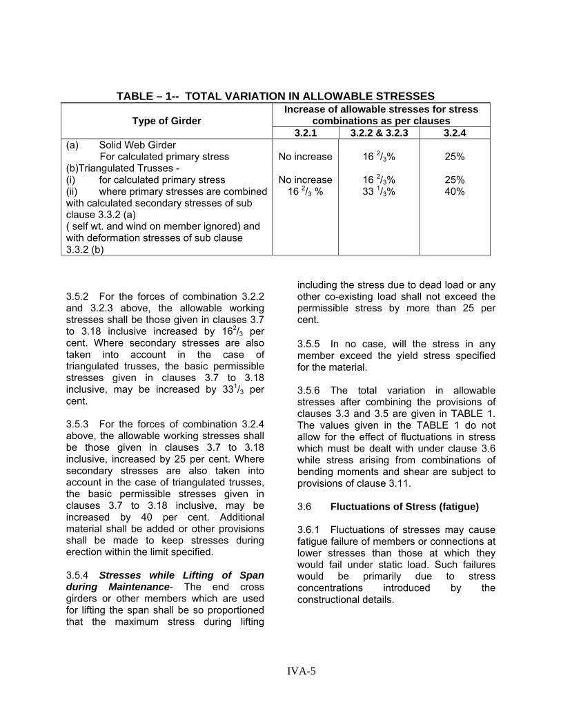
3.5.2 For the forces of combination 3.2.2 and 3.2.3 above, the allowable working stresses shall be those given in clauses 3.7 to 3.18 inclusive increased by 162/3 per cent. Where secondary stresses are also taken into account in the case of triangulated trusses, the basic permissible stresses given in clauses 3.7 to 3.18 inclusive, may be increased by 331/3 per cent. 3.5.3 For the forces of combination 3.2.4 above, the allowable working stresses shall be those given in clauses 3.7 to 3.18 inclusive, increased by 25 per cent. Where secondary stresses are also taken into account in the case of triangulated trusses, the basic permissible stresses given in clauses 3.7 to 3.18 inclusive, may be increased by 40 per cent. Additional material shall be added or other provisions shall be made to keep stresses during erection within the limit specified. 3.5.4 Stresses while Lifting of Span during Maintenance- The end cross girders or other members which are used for lifting the span shall be so proportioned that the maximum stress during lifting
including the stress due to dead load or any other co-existing load shall not exceed the permissible stress by more than 25 per cent.
3.5.5 In no case, will the stress in any member exceed the yield stress specified for the material. 3.5.6 The total variation in allowable stresses after combining the provisions of clauses 3.3 and 3.5 are given in TABLE 1. The values given in the TABLE 1 do not allow for the effect of fluctuations in stress which must be dealt with under clause 3.6 while stress arising from combinations of bending moments and shear are subject to provisions of clause 3.11. 3.6 Fluctuations of Stress (fatigue) 3.6.1 Fluctuations of stresses may cause fatigue failure of members or connections at lower stresses than those at which they would fail under static load. Such failures would be primarily due to stress concentrations introduced by the constructional details.
TABLE – 1-- TOTAL VARIATION IN ALLOWABLE STRESSES
IVA-5

3.6.2 All details shall be designed to avoid as far as possible stress concentrations likely to result in excessive reductions of the fatigue strength of members or connections. Care shall be taken to avoid a sudden reduction of the section of a member or a part of a member, especially where bending occurs.
3.6.3 Stresses due to dead load, live load and impact, stresses resulting from curvature and eccentricity of track and secondary stresses as defined in clause 3.3.2 (a) only shall be considered for effects due to fatigue. All other items mentioned in clause 3.1 and secondary stresses as defined in clause 3.3.2(b) shall be ignored when considering fatigue.
3.6.4 - For any structural member or connection, the fatigue assessment shall be made as per Appendix 'G' (revised) for a specified 'Design Life' and 'Fatigue Load Model'. The trains comprising the fatigue load models shall be in accordance with Bridge Rules.
Clause 3.6.5 - The fatigue life assessment shall be made for a standard design life of 100 years for a standard GMT of 50.
Note: - No allowance for fatigue need be made in the design of Foot Over Bridges.
(Addendum & Correction Slip No. 18 dated 07-06-2012)
3.6.6. Connection riveted or bolted- The number of rivets and bolts shall be calculated without any allowance for fatigue but rivets or bolts subjected to reversal of stress during passage of live load shall be designed for the arithmetical sum of the maximum load plus 50% of the reversed load. In the case of wind bracings, the connection shall be designed to resist the greater load only.
3.6.7. The welds shall be designed according to the permissible stresses given in IRS Welded Bridge Code.
3.7 Permissible Stresses- Subject to the provision of clauses 3.3, 3.5, 3.6,3.8 to 3.11 of this Code, structures shall be so designed that the calculated stresses in structural steel do not exceed the basic values given in TABLE II.
3.8 Allowable Working stresses for Parts in Axial Compression- The calculated average working stress in compression member shall not exceed the value given in TABLE IV or IV (a) derived from the Formula given below (see also APPENDIX-B)
RADIANS /4EmPSec(//r 0008//r)(0.181PP
ac ac
++=
Where, Pac = allowable working stress on effective cross section for compression member.
P = values depending upon the yield stress fy of the material (see TABLE III).
m = load factor = 1.7.
E = Young’s modulus = 21,100 kg/mm2 =(13,400 tons/sq in).
r = least radius of gyration of compression member.
l = effective length of the compression member (See clause 4.2).
IVA-6

TABLE II - BASIC PERMISSIBLE STRESSES IN STRUCTURAL STEEL Mild steel to IS: 226 and IS:
2062 with yield stress of High tensile steel grade 58-HTC to IS: 961 with yield
stress of Description 26 kg/
mm2 16.5
ton/in224 kg/ mm2
15.2 ton/in2
36 kg/ mm2
22.9 ton/in2 35 kg/ mm2 22.0
ton/in233 kg/ mm2
21.0 ton/in2
1 2 3 4 5 6 7 8 9 10 11 Parts in Axial Tension On effective sectional area … Parts in Axial Compression on Effective gross section … Parts in bending (Tension or Compression). On effective sectional area for extreme fibre stress – (i) For plates, flats, tubes, rounds,
square and similar sections.
15.4
17.0
9.8
10.8
14.2
15.7
9.0
10.0
21.3
See
23.5 See
13.5
Clause
14.9 also
20.7
3.8
22.8Clause3.9
13.1
14.5
19.5
21.6
12.4
13.7
(ii) For rolled beams, channels, angles and tees, and for plate girders with single or multiple webs with d1/t not greater than 85 for steel to IS:226 and IS:2062 d1/t not greater than 75 for steel to IS:961.
ii) For plate girder with single ormultiple webs with : d1 /t greaterthan 85 for steel to IS:226 andIS:2062, d/t greater than 75 forsteel to IS:961.
16.3
15.4
10.4
9.8
15.0
14.2
9.5
9.0
22.5 See
21.3 See
14.3 also
13.5 also
21.9Clause 3.9
20.7Clause 3.9
13.9
13.1
20.6
19.5
13.1
12.4
NOTE:- In the above, d1 is the clear distance between flange angles or, where there are no flange angles, between flanges (ignoring fillets); but where tongue plates having a thickness not less than twice the thickness of the web plate are used. d1 is the depth of the girder between the flanges less the sum of the depth of the tongue plates or eight times the sum of thickness of the tongue plates, whichever is the lesser. t is the web thickness. ( contd.)
IVA-7

TABLE II – (Contd.) 1 2 3 4 5 6 7 8 9 10 11
11.1
9.4
7.0
6.0
10.2
8.7
6.5
5.5
15.3
13.0
9.7
8.3
14.9
12.7
9.5
8.1
14.0
12.0
8.9
7.6
Parts in Shear Maximum shear stress (Having regard to the distribution of stresses in conformity with the elastic behaviour of the member in flexure) …
Average shear stress (on the gross effective sectional area of webs of plate girders, rolled beams, channels, angles, tees) …
For stiffened webs see clauses 5.8 and 5.10. Parts in Bearing On flat surfaces … 18.9 kg/mm²(12.0 Ton/in.²); 26.0 kg/mm² (16.5 Ton/in.²).
Mild steel to IS:226 and IS:2062 and carbon steel (class 2) to IS:1875
High tensile steel Grade 58-HTC to IS:961 and Carbon Steel (class 4) to IS:1875 Description
Kg/mm² Ton/in.² Kg/mm² Ton/in.²1 2 3 4 5
Pins In shear …
In bearing …
In bending …
For turned and fitted knuckle pins and spheres in bearing: On projected area …
10.2
21.3
21.3
11.8
6.5
13.5
13.5
7.5
14.2
29.9
29.9
11.8
9.0
19.0
19.0
7.5 Contd….
IVA-8

TABLE – II – (Contd.)
Material of bolts as per IS: 1367 - Property Class Rivets bars to --------
4.6 6.6 IS: 1148* IS: 1149 Description
Kg/mm² Ton/in.² Kg/mm² Ton/in.² Kg/mm² Ton/in.² Kg/mm² Ton/in.² 1 2 3 4 5 6 7 8 9
Bolts and Rivets Parts in Axial Tension (a) On net section of bolts and studs. (i) Over 38 mm (1.1/2”) dia … (ii) 28 mm (1.1/8”) and over including 38 mm (1.1/2”) dia … (iii) Less than 28 mm (1-1/8”) dia but not less than 22 mm (7/8”) dia. (iv) Less than 22 mm (7/8”) dia … (b) On rivets …
14.2
12.6
11.09.4….
9.0
8.0
7.06.0….
19.7
18.9
16.514.2
….
12.5
12.0
10.59.0….
See
….
….
….….9.4
Clause
….
….
….….6.0
7.9
….
….
….….
11.1
….
….
….….7.0
Parts in Shear Average shear stress – (a) On power driven shop rivets
and turned and fitted bolts … (b) On power driven field rivets … (c) On hand driven rivets … (d) On black bolts ... (e) On precision bolts and semi-
precision bolts. … *NOTE – Rivets from drawn wire not included.
10.2……
7.9
9.4
6.5……
5.0
6.0
14.2………
13.4
See
9.0………
8.5
Clauses
10.29.48.7…
…
7.6, 7.7
6.56.05.5…
… and 7.8
14.213.4
……
…
9.08.5……
…
IVA-9

Table II (Contd…)
1 2 3 4 5 6 7 8 9 Parts in Bearing (a) On power driven shop rivets
and turned and fitted bolts … (b) On power driven field rivets… (c) On hand driven rivets … (d) On black bolts … (e) On precision bolts and semi-
precision bolts. …
23.6……
15.8
22.0
15.0……
10.0
14.0
32.3………
30.7See
20.5………
19.5Clauses
23.622.018.9
…
…7.6, 7.7
15.014.012.0
…
…and 7.8.
32.330.7
……
…
20.519.5
……
…
Welds See I.R.S Welded Bridge Code Note:- For steels to IS:226, IS:2062 and IS:961 a summary of guaranteed yield stress for various thicknesses is given below. For
beams and channels, the thickness of the web governs. Guaranteed yield stress
Mild steel to IS:226 and IS:2062 High tensile steel grade 58-HTC to IS:961 Description 26 kg/mm²
24 kg/mm²
23 kg/mm²
36 kg/mm²
35 kg/mm²
33 kg/mm²
30 kg/mm²
1 2 3 4 5 6 7 8 Nominal thickness/ diameter of plates, sections (for example, angles, tees, beams, channels, etc.), and flats. … Bars (rounds, square and hexagonal) …
6 mm up to and including 20 mm. 10 mm up to and including 20 mm.
Over 20 mm up to and including 40 mm. Over 20 mm.
Over 40 mm.
…
6 mm up to and including 28 mm.
-do-
Over 28 mm up to and including 45 mm.
-do-
Over 45 mm up to and including 63 mm.
-do-
Over 63 mm.
-do-
IVA-10

TABLE III – VALUES OF ‘P’ FOR VARIOUS VALUES OF fy, THE YIELD STRESS FOR MILD STEEL AND HIGH TENSILE STEEL
Yield Stress fy P Steel Kg/mm2 Ton/in2 Kg/mm2 Ton/in2 Mild steel to IS:226 & IS:2062 … HTS to IS:961 …
26.0
24.0
36.0
35.0
33.0
16.5
15.2
22.9
22.2
21.0
17.8
16.5
24.8
24.1
22.6
11.3
10.5
15.8
15.3
14.4
TABLE IV – ALLOWABLE WORKING STRESSES Pac IN Kg/mm² ON EFFECTIVE CROSS SECTION FOR AXIAL COMPRESSION
Mild steel to IS:226 and IS:2062 High tensile steel to IS:961 l/r P=16.5 P=17.8 P=22.6 P=24.1 P=24.8
0 … 20 … 40 …
60 … 80 …
100 … 120 … 140 … 160 …
13.98 13.66 12.99 11.82 10.07 8.07 6.30 4.94 3.93
15.08 14.72 13.95 12.59 10.57 8.32 6.43 5.01 3.98
19.15 18.63 17.43 15.18 12.04 9.04 6.78 5.20 4.09
20.42 19.85 18.48 15.92 12.35 9.21 6.86 5.25 4.11
21.02 20.42 18.98 16.25 12.58 9.28 6.00 5.27 4.12
IVA-11

TABLE IV (a) – ALLOWABLE WORKING STRESSES Pac IN Ton/in.² ON EFFECTIVE CROSS SECTION FOR AXIAL COMPRESSION
Mild steel to IS:226 and IS:2062 High tensile steel to IS:961 l/r P=10.5 P=11.3 P=14.4 P=15.3 P=15.8
0 … 20 … 40 … 60 … 80 …
100 … 120 … 140 … 160 …
8.88 8.67 8.25 7.50 6.39 5.12 4.00 3.14 2.49
9.57 9.35 8.86 7.99 6.71 5.28 4.08 3.18 2.53
12.16 11.83 11.07 9.64 7.64 5.74 4.30 3.30 2.60
12.97 12.60 11.73 10.11 7.84 5.85 4.35 3.33 2.61
13.35 12.97 12.05 10.32 7.99 5.89 4.38 3.35 2.62
IVA-12


3.9 Allowable Working Stresses in Bending- For all sectional shapes the tensile and compressive bending stresses, fbt and fbc, calculated according to clauses 5.1 to 5.3, shall not exceed the appropriate basic permissible stresses in clause 3.7 Table II subject to the provisions in clause 3.9.1 for bending compression 3.9.1 Bending Compression - For sectional shape with Iy smaller than Ix where Iy = moment of inertia of the whole section about the axis lying in the plane of bending (the y-y axis) and Ix = moment of inertia of the whole section about the axis normal to the plane of bending (the x-x axis) The bending compression stress, fbc shall not exceed the value Pbc given in Table VIII, corresponding to Cs the critical stress in the compression element calculated as follows:- 3.9.1.1 for sections with a single web: (including I sections with stiffened or unstiffened edges, channels, angles, tees, etc but excluding I sections where the thickness of one flange is more than 3 times the thickness of the other flange): (a) Where the flanges have equal moments of inertia about y-y axis.
Cs= 2)(267730
yrl
)⎪⎭
⎪⎬⎫
⎪⎩
⎪⎨⎧+
2(
2011
Drlt
y
e2/ mmkg =A
Except that the value of Cs calculated above shall be increased by 20 per cent for rolled beams and channels, and for plate girders provided that:
te/t is not greater than 2 di/t is not greater than 85, for steel to IS:226 and IS:2062
d1/t is not greater than 75, for steel to Grade 58-HTC of IS:961.
In the above,
l=effective length of compression flange (see clause 5.4)
ry=radius of gyration about the y-y axis of the gross section of the whole girder, at the point of maximum bending moment.
D=overall depth of girder, at the point of maximum bending moment
te=effective thickness of the compression flange =K1 x mean thickness of the horizontal portion of the compression flange at the point of maximum bending moment. (For rolled section, te=k1 x thickness given in reference books)
The coefficient K1 makes allowance for reduction in thickness or breadth of flanges between points of effective lateral restraint and depends on Ra, the ratio of the total area of both flanges at the point of least bending moment to the corresponding area at the point of greater bending moment between such points of restraint. (for flanges of constant area K1=1). d1 & t are as defined in table II for parts in bending. Flanges shall not be reduced in breadth to give a value of Ra lower than 0.25 Note:- To obtain Cs in ton/sq in replace the constant 267730 in the above formula by 1,70,000
Value of K1 for different values of Ra, are given in the Table V
TABLE V – VALUES OF K1 Ra 1.0 0.9 0.8 0.7 0.6 0.5 0.4 0.3 0.2 0.1 0.0 K1 1.0 1.0 1.0 0.9 0.8 0.7 0.6 0.5 0.4 0.3 0.2
IVA-13

Note:- Where the value of Ra calculated for the compression flange alone is smaller than that when both flanges are combined, this smaller value of Ra shall be used. (b) Where the moment of inertia of the compression flange about the y-y axis exceeds that of the tension flange.
Cs ( )2267730
yrl=
⎪⎭
⎪⎬⎫
⎪⎩
⎪⎨⎧+ 2)(
2011
Drlt
y
e+ ( )22
267730
yrl
K
2/ mmkg = A + K2B Where l, ry and D are as defined in (a) above, and te= effective thickness of flange = K1 x mean thickness of the horizontal portion of the flange of greater moment of inertia about the y-y axis of the girder, at the point of maximum bending moment, where K1 is obtained from Table V K2 = A coefficient to allow for inequality of tension and compression flanges, and depends on Rm, the ratio of the moment of inertia of the compression flanges alone to that of the sum of the moments of inertia of the compression and tension flanges, each calculated about its own axis parallel to the y-y axis of the girder, at the point of maximum bending moment Note: 1. For flanges of equal moment of inertia Rm-
0.5 and K2 = 0 For tees and angles Rm=1.0 and K2=0.5
2. To obtain Cs in ton/in2 replace the constant 267730 in the above formula by 1,70,000
Value of K2 for different values of Rm, are given in the Table VI
TABLE VI – VALUES OF K2 Rm 1.0 0.9 0.8 0.7 0.6 0.5 0.4 0.3 0.2 0.1 0.0
K2 0.5 0.4 0.3 0.2 0.1 0.0 -0.2 -0.4 -0.6 -0.8 -1.0
(c) Where the moment of inertia of the tension flange about the y-y axis exceeds that of the compression flange. Cs
( ) ( ) t
c
yy
e
yYY
xrl
KDr
lt
rl ⎥⎥⎥
⎦
⎤
⎢⎢⎢
⎣
⎡+
⎪⎭
⎪⎬⎫
⎪⎩
⎪⎨⎧+= 22
22
267730)(2011267730
2/ mmkg
( )tc2 y / (y x B)K A += Where l, ry, D, te, & K2 are as defined above and Yc = distance from the neutral axls of girder
to extreme fibre in compression Yt = distance from neutral axis of girder to
extreme fibre in tension To obtain Cs in ton/in2, replace the constant 267730 in the above formula by 170000. Values of K2 for different values of Rm are given in table VI For tees and angles, Rm = 0 and K2 = -1 Note :- 1. For values of ‘A’ and ‘B’ for different ratios
of l/ry and D/te to be used for calculating Cs in kg/mm2 refer Table VII and [Cs in tons/in2 refer Table VII (a)]
2. For values of allowable bending compressive
stress Pbc for different values of Cs see Table VIII
3.9.1.2 For sections other than those described in clause 3.9.1.1. above: a) Where the section is symmetrical about the x-x axis, the value of Cs may be obtained from the basic equation in the APPENDIX C b) Where the section is not symmetrical about the x-x axis, the exact value of Cs may be computed: but values obtained from the formulae 3.9.1.1. (b) and 3.9.1.1.(c) can be used with safety.
IVA-14

TABLE VII – VALUES OF A & B TO BE USED FOR CALCULATING VALUES OF Cs IN kg/ mm²
Where ⎪⎭
⎪⎬⎫
⎪⎩
⎪⎨⎧
⎟⎟⎠
⎞⎜⎜⎝
⎛+=
2
y
e2
y rlt
201 1
)(l/r267730 A
D
2y )(l/r
267730 B =
NOTE – Where flanges are equal and of constant cross section Cs = A. A l
ry D te
8 10 12 14 16 18 20 25 30 35 40 50 60 80 100 B
40 251.0 224.6 208.7 198.6 191.8 186.9 183.2 177.6 174.7 172.8 171.5 170.1 169.1 168.4 168.0 167.4 45 212.5 187.7 172.6 162.8 156.2 151.5 147.9 142.5 139.5 137.5 136.4 134.7 134.0 133.2 132.9 132.2 50 184.1 160.6 146.5 137.0 130.7 126.1 122.7 117.3 114.3 112.4 111.2 109.8 109.0 108.2 107.7 107.1 55 162.4 140.3 126.8 117.8 111.7 107.2 103.8 98.7 95.8 93.9 92.6 91.2 90.4 89.5 89.1 88.5 60 145.2 124.4 111.5 103.0 97.0 92.8 89.5 84.4 81.4 79.7 78.4 77.0 76.2 75.4 75.0 74.3 65 131.5 111.8 99.5 91.3 85.7 81.6 78.3 73.2 70.4 68.7 67.4 66.0 65.2 64.4 63.9 63.3 70 120.0 101.4 89.8 81.9 76.4 72.4 69.5 64.4 61.6 59.8 58.6 57.3 56.5 55.8 55.3 54.6 75 110.6 93.1 81.7 74.3 69.0 65.0 62.0 57.3 54.5 52.8 51.7 50.2 49.5 48.7 48.2 47.6 80 102.5 85.7 75.1 67.9 62.7 59.1 56.1 51.5 48.7 46.9 45.8 44.4 43.6 42.9 42.5 41.9 85 95.6 79.5 69.4 62.5 57.5 53.9 51.2 46.6 43.8 42.2 41.1 39.7 38.9 38.1 37.8 37.0 90 89.5 74.3 64.6 58.0 53.1 49.6 46.9 42.5 39.8 38.1 37.0 35.6 34.8 34.0 33.7 33.1 95 84.3 69.6 60.3 54.0 49.3 45.8 43.3 38.9 36.4 34.6 33.5 32.3 31.5 30.7 30.4 29.6 100 79.5 65.5 56.5 50.4 46.0 42.7 40.2 35.9 33.4 31.8 30.7 29.3 28.5 27.9 27.4 26.8 110 71.5 58.7 50.4 44.7 40.6 37.5 35.1 31.0 28.7 27.1 26.0 24.7 23.9 23.1 22.8 22.2 120 65.0 53.2 45.5 40.2 36.4 33.4 31.2 27.2 25.0 23.5 22.4 21.1 20.3 19.7 19.2 18.6 130 59.7 48.7 41.6 36.5 32.9 30.1 28.0 24.2 22.0 20.6 19.5 18.3 17.6 16.9 16.5 15.9 140 55.1 44.9 38.1 33.4 30.1 27.4 25.4 21.9 19.7 18.3 17.3 16.1 15.4 14.6 14.3 13.7
TABLE VII – VALUES OF A & B TO BE USED FOR CALCULATING VALUES OF Cs IN kg/ mm²
IVA-15
Where⎪⎭
⎪⎬⎫
⎪⎩
⎪⎨⎧
⎟⎟⎠
⎞⎜⎜⎝
⎛+=
2
y
e2
y rlt
201 1
)(l/r267730 A
D
2y )(l/r
267730 B =
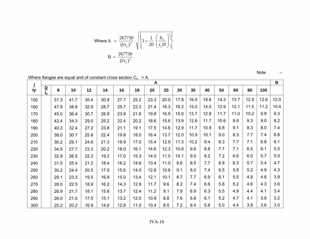
Note – Where flanges are equal and of constant cross section Cs = A.
A B l ty D
te 8 10 12 14 16 18 20 25 30 35 40 50 60 80 100
150 160 170 180 190 200 210 220 230 240 250 260 270 280 290 300
51.3 47.9 45.0 42.4 40.2 38.0 36.2 34.5 32.9 31.5 30.2 29.1 28.0 26.9 26.0 25.2
41.7 38.9 36.4 34.3 32.4 30.7 29.1 27.7 26.5 25.4 24.4 23.3 22.5 21.7 21.0 20.2
35.4 32.9 30.7 29.0 27.2 25.8 24.6 23.3 22.2 21.2 20.5 19.5 18.9 18.1 17.5 16.9
30.9 28.7 26.8 25.2 23.8 22.4 21.3 20.2 19.2 18.4 17.6 16.9 16.2 15.6 15.1 14.6
27.7 25.7 23.9 22.4 21.1 19.8 18.9 18.0 17.0 16.2 15.6 15.0 14.3 13.7 13.2 12.8
25.2 23.3 21.6 20.2 19.1 18.0 17.0 16.1 15.3 14.6 14.0 13.4 12.9 12.4 12.0 11.5
23.3 21.4 19.8 18.6 17.5 16.4 15.4 14.6 14.0 13.4 12.8 12.1 11.7 11.2 10.9 10.4
20.018.316.915.614.613.712.912.311.511.010.610.19.6 9.1 8.8 8.5
17.8 16.2 15.0 13.9 12.9 12.0 11.3 10.6 10.1 9.6 9.1 8.7 8.2 7.9 7.6 7.2
16.5 15.0 13.7 12.6 11.7 10.9 10.2 9.6 9.0 8.5 8.0 7.7 7.4 6.9 6.8 6.4
15.6 14.0 12.8 11.7 10.9 10.1 9.4 8.8 8.2 7.7 7.4 6.9 6.6 6.3 6.1 5.8
14.3 12.9 11.7 10.6 9.8 9.0 8.3 7.7 7.2 6.8 6.5 6.1 5.8 5.5 5.2 5.0
13.7 12.1 11.0 9.9 9.1 8.3 7.7 7.1 6.6 6.3 5.8 5.5 5.2 4.9 4.7 4.4
12.9 11.5 10.2 9.3 8.3 7.7 7.1 6.5 6.0 5.7 5.2 4.9 4.6 4.4 4.1 3.9
12.6 11.2 9.9 9.0 8.0 7.4 6.8 6.1 5.7 5.4 4.9 4.6 4.3 4.1 3.8 3.6
12.010.49.3 8.2 7.4 6.8 6.1 5.5 5.0 4.7 4.3 3.9 3.6 3.4 3.2 3.0
IVA-16
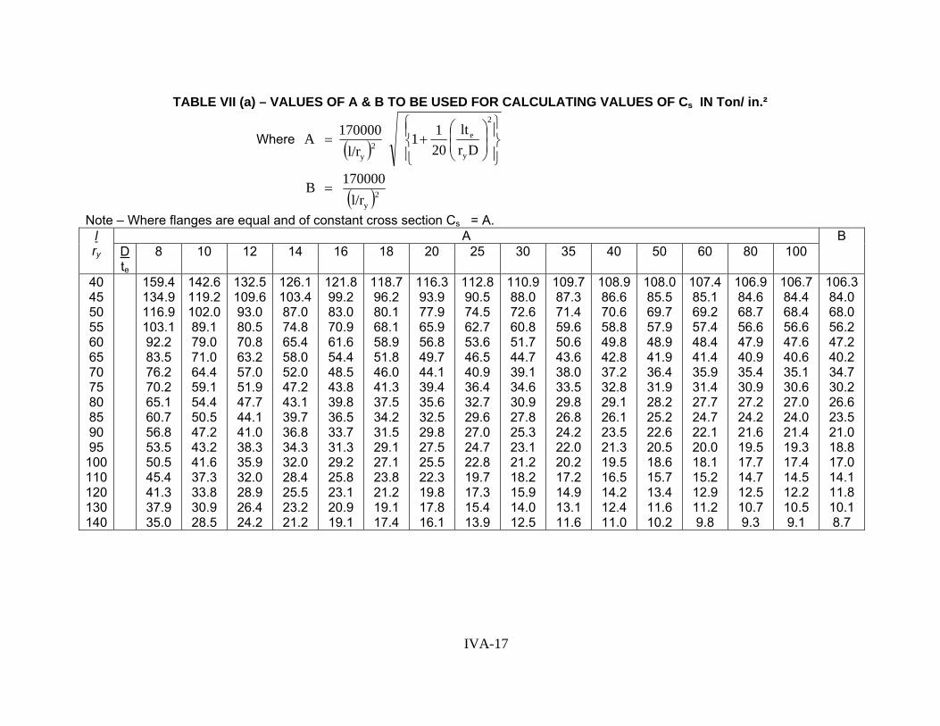
TABLE VII (a) – VALUES OF A & B TO BE USED FOR CALCULATING VALUES OF Cs IN Ton/ in.²
Where ( ) ⎪⎭
⎪⎬⎫
⎪⎩
⎪⎨⎧
⎟⎟⎠
⎞⎜⎜⎝
⎛+=
2
y
e2
y Drlt
201 1
l/r170000 A
( )2yl/r170000 B =
Note – Where flanges are equal and of constant cross section Cs = A. A l
ry D te
8 10 12 14 16 18 20 25 30 35 40 50 60 80 100 B
40 45 50 55 60 65 70 75 80 85 90 95
100 110 120 130 140
159.4 134.9 116.9 103.1 92.2 83.5 76.2 70.2 65.1 60.7 56.8 53.5 50.5 45.4 41.3 37.9 35.0
142.6 119.2 102.0 89.1 79.0 71.0 64.4 59.1 54.4 50.5 47.2 43.2 41.6 37.3 33.8 30.9 28.5
132.5 109.6 93.0 80.5 70.8 63.2 57.0 51.9 47.7 44.1 41.0 38.3 35.9 32.0 28.9 26.4 24.2
126.1103.487.0 74.8 65.4 58.0 52.0 47.2 43.1 39.7 36.8 34.3 32.0 28.4 25.5 23.2 21.2
121.899.2 83.0 70.9 61.6 54.4 48.5 43.8 39.8 36.5 33.7 31.3 29.2 25.8 23.1 20.9 19.1
118.796.2 80.1 68.1 58.9 51.8 46.0 41.3 37.5 34.2 31.5 29.1 27.1 23.8 21.2 19.1 17.4
116.393.9 77.9 65.9 56.8 49.7 44.1 39.4 35.6 32.5 29.8 27.5 25.5 22.3 19.8 17.8 16.1
112.890.5 74.5 62.7 53.6 46.5 40.9 36.4 32.7 29.6 27.0 24.7 22.8 19.7 17.3 15.4 13.9
110.988.0 72.6 60.8 51.7 44.7 39.1 34.6 30.9 27.8 25.3 23.1 21.2 18.2 15.9 14.0 12.5
109.787.3 71.4 59.6 50.6 43.6 38.0 33.5 29.8 26.8 24.2 22.0 20.2 17.2 14.9 13.1 11.6
108.986.6 70.6 58.8 49.8 42.8 37.2 32.8 29.1 26.1 23.5 21.3 19.5 16.5 14.2 12.4 11.0
108.085.5 69.7 57.9 48.9 41.9 36.4 31.9 28.2 25.2 22.6 20.5 18.6 15.7 13.4 11.6 10.2
107.485.1 69.2 57.4 48.4 41.4 35.9 31.4 27.7 24.7 22.1 20.0 18.1 15.2 12.9 11.2 9.8
106.984.6 68.7 56.6 47.9 40.9 35.4 30.9 27.2 24.2 21.6 19.5 17.7 14.7 12.5 10.7 9.3
106.784.4 68.4 56.6 47.6 40.6 35.1 30.6 27.0 24.0 21.4 19.3 17.4 14.5 12.2 10.5 9.1
106.384.0 68.0 56.2 47.2 40.2 34.7 30.2 26.6 23.5 21.0 18.8 17.0 14.1 11.8 10.1 8.7
IVA-17

TABLE VII (a) – VALUES OF A & B TO BE USED FOR CALCULATING VALUES OF Cs IN Ton/ in.²
Where ( ) ⎪⎭
⎪⎬⎫
⎪⎩
⎪⎨⎧
⎟⎟⎠
⎞⎜⎜⎝
⎛+=
2
y
e2
y Drlt
201 1
l/r170000 A
( )2yl/r170000 B =
Note – Where flanges are equal and of constant cross section Cs = A. A l
ry D te
8 10 12 14 16 18 20 25 30 35 40 50 60 80 100 B
150 160 170 180 190 200 210 220 230 240 250 260 270 280 290 300
32.6 30.4 28.6 26.9 25.5 24.1 23.0 21.9 20.9 20.0 19.2 18.5 17.8 17.1 16.5 16.0
26.5 24.7 23.1 21.8 20.6 19.5 18.5 17.6 16.8 16.1 15.5 14.8 14.3 13.8 13.3 12.8
22.5 20.9 19.5 18.4 17.3 16.4 15.6 14.8 14.1 13.5 13.0 12.4 12.0 11.5 11.1 10.7
19.6 18.2 17.0 16.0 15.1 14.2 13.5 12.8 12.2 11.7 11.2 10.7 10.3 9.9 9.6 9.3
17.6 16.3 15.2 14.2 13.4 12.6 12.0 11.4 10.8 10.3 9.9 9.5 9.1 8.7 8.4 8.1
16. 14.8 13.7 12.8 12.1 11.4 10.8 10.2 9.7 9.3 8.9 8.5 8.2 7.9 7.6 7.3
14.8 13.6 12.6 11.8 11.1 10.4 9.8 9.3 8.9 8.5 8.1 7.7 7.4 7.1 6.9 6.6
12.7 11.6 10.7 9.9 9.3 8.7 8.2 7.8 7.3 7.0 6.7 6.4 6.1 5.8 5.6 5.4
11.3 10.3 9.5 8.8 8.2 7.6 7.2 6.7 6.4 6.1 5.8 5.5 5.2 5.0 4.8 4.6
10.5 9.5 8.7 8.0 7.4 6.9 6.5 6.1 5.7 5.4 5.1 4.9 4.7 4.4 4.3 4.1
9.9 8.9 8.1 7.4 6.9 6.4 6.0 5.6 5.2 4.9 4.7 4.4 4.2 4.0 3.9 3.7
9.1 8.2 7.4 6.7 6.2 5.7 5.3 4.9 4.6 4.3 4.1 3.9 3.7 3.5 3.3 3.2
8.7 7.7 7.0 6.3 5.8 5.3 4.9 4.5 4.2 4.0 3.7 3.5 3.3 3.1 3.0 2.8
8.2 7.3 6.5 5.9 5.3 4.9 4.5 4.1 3.8 3.6 3.3 3.1 2.9 2.8 2.6 2.5
8.0 7.1 6.3 5.7 5.1 4.7 4.3 3.9 3.6 3.4 3.1 2.9 2.7 2.6 2.4 2.3
7.6 6.6 5.9 5.2 4.7 4.3 3.9 3.5 3.2 3.0 2.7 2.5 2.3 2.2 2.0 1.9
IVA-18

TABLE VIII – ALLOWABLE WORKING STRESS Pbc. FOR DIFFERENT VALUES OF CRITICAL STRESS Cs .
(SEE ALSO CLAUSE 3.7 TABLE II) Cs Pbc for steel
to IS:226 & IS:2062
Pbc for steel to Grade
58-HTC of IS:961
Cs Pbc for steel to IS:226 &
IS:2062
Pbc for steel to Grade
58-HTC of IS:961
Kg/mm² Kg/mm² Kg/mm² Ton/in.² Ton/in.² Ton/in.² 3 4 5 6 7 8 9
10 12 14 16 18 20 22 24 26 28 30 35 40 45 50 55 60 65 70 75 80 90
100 125 150 200 215
1.5 2.0 2.5 3.0 3.5 3.8 4.2 4.6 5.3 6.0 6.7 7.2 7.6 8.0 8.4 8.8 9.2 9.6
10.5 11.2 11.9 12.4 12.9 13.3 13.6 13.9 14.1 14.4 14.9 15.3 15.8 15.8 15.8 15.8
1.5 2.0 2.5 3.0 3.5 3.8 4.2 4.6 5.4 6.2 7.0 7.7 8.4 9.0 9.6
10.2 10.8 11.4 12.7 13.7 14.6 15.3 15.9 16.5 17.1 17.4 17.8 18.2 18.8 19.4 20.5 21.2 22.2 22.4
2 3 4 5 6 7 8 9
10 12 14 16 17 18 20 22 24 26 28 30 35 40 45 50 55 60 70 80 90
100 110 120 127 135
1.0 1.5 2.0 2.4 2.8 3.2 3.5 3.9 4.2 4.7 5.1 5.5 5.7 5.9 6.3 6.6 7.0 7.2 7.5 7.7 8.2 8.6 8.9 9.1 9.4 9.6 9.9
10.0 10.0 10.0 10.0 10.0 10.0 10.0
1.0 1.5 2.0 2.4 2.8 3.2 3.6 4.0 4.4 5.1 5.7 6.3 6.6 6.9 7.5 8.0 8.4 8.8 9.2 9.5
10.1 10.7 11.1 11.5 11.8 12.1 12.6 13.0 13.3 13.6 13.8 14.0 14.1 14.2
IVA-19


3.10 Allowable Shear Stress in solid Webs of Plate Girders- The calculated average shear stress fs on the effective sectional area of the web (see clause 4.3.2.3) shall not exceed the value given in TABLE II, clause 3.7 3.11. Combined Stresses 3.11.1 Bending and Axial Stresses- Members subjected to both axial and bending stresses (compressive or tensile) shall be so proportioned that the quantity
unity exceednot does Ff
Ff
b
b1
a
a1
+
Where, f1a= calculated axial stress (compressive or
tensile) Fa= appropriate allowable working stress
in axially loaded members. f1b= calculated maximum bending
(compressive or tensile) stresses about both principal axes including secondary stresses, if any
Fb= the appropriate allowable working stress in bending (compressive or tensile)
Note:- Where an increase or reduction in permissible working stress is specified, both Fa and Fb shall be the increased or reduced working stress ns directed in the relevant clauses. 3.11.2 Shear and Bending Stresses – The equivalent stress (see clause 3.11.4) ‘fe’, due to a combination of shear stress ‘fs’ , bending stress ‘fb’, tensile or compressive is calculated from:
fe = 22 3 sb ff +
3.11.3 Shear, Bending, and Bearing stresses- The equivalent stress ‘fe’, (see clause 3.11.4) due to a combination of shear stress ‘fs’ bearing stress ‘fp and bending stress ‘fb’ tensile or compressive is calculated from:
fe =222 3 spbp fffff b +++
3.11.4 Irrespective of the permissible increase of stress given in clauses 3.3 to 3.5 the equivalent stress ‘fe‘ calculated in clauses 3.11.2 and 3.11.3 above shall not exceed the following values given in TABLE IX.
TABLE IX-MAXIMUM PERMISSIBLE VALUES OF THE EQUIVALENT STRESS fe FOR MILD AND HIGH TENSILE STEEL
Yield Stress Maximum value of fe Quality of steel
Kg/mm2 Ton/in2 Kg/mm2 Ton/in2
26.0 16.5 24.0 15.2 Mild steel to IS: 226 and IS: 2062 …
24.0 15.2 22.0 14.0
36.0 22.9 33.0 21.0
35.0 22.2 32.0 20.3
High tensile steel to IS: 961 …
33.0 21.0 30.0 19.1
IVA-20

3.12 Allowable Working Loads on Cylindrical Roller and Spherical Expansion Bearings 3.12.1 Cylindrical and spherical bearings shall be of forged steel to class 3 of IS:2004 and IS:1875 steel or alternatively turned from carriage and wagon axles, and the allowable working load shall not exceed the value given below: 3.12.2 Cylindrical rollers on curved surfaces- The allowable working load per unit length of roller shall be: (a) For single and double rollers,
length of mmper kg I/DI/D
1 0.821⎟⎟⎠
⎞⎜⎜⎝
⎛−
length ofinch per ton I/DI/D
1 0.521⎟⎟⎠
⎞⎜⎜⎝
⎛−
(b) For three or more rollers,
length of mmper kg I/DI/D
1 0.521⎟⎟⎠
⎞⎜⎜⎝
⎛−
length ofinch per ton I/DI/D
1 0.3221⎟⎟⎠
⎞⎜⎜⎝
⎛−
Where D1 and D2 are diameters of the convex and concave contact surfaces respectively. 3.12.3 Cylindrical Rollers on Flat Surfaces- The allowable working load per unit length of roller shall be: (a) For single and double rollers
0.8 D3 kg per mm of length 0.5 D3 ton per inch of length
(b) For three or more rollers
0.5 D3 kg per mm of length 0.32 D3 ton per inch of length
Where D3 is the diameter of the roller Note:- No roller shall be lesser of diameter than 102 mm (or 4 inches) 3.12.4 The allowable working load on spherical bearings shall be:
kg 2
21 I/DI/D1
1271
⎥⎦
⎤⎢⎣
⎡−
or ton2
21 I/DI/D1
2001
⎥⎦
⎤⎢⎣
⎡−
Where D1 and D2 are defined in clause 3.12.2 above. 3.13 Allowable Working Pressure on Sliding Bearings- The allowable working pressure for steel sliding on hard copper alloys to IS: 1458 shall not exceed 3.2 kg/mm2 (2ton/in2) 3.14 Basic Permissible Stresses for Cast Steel in Bearings- The basic permissible stresses for cast steel to IRS M2, class ’C’ large and important casting with a minimum tensile strength of 47.25 kg/mm2 (30 ton/in2) and with a minimum elongation of 20 per cent in bearings shall not exceed the basic permissible stresses specified in clause 3.7, TABLE II for mild steel to IS: 226 with yield stress of 24.0 kg/mm2 (15.2 tons/in2) 3.15 Cast Iron- Cast iron shall not be used in any portion of the structure of a bridge carrying a railway except when subject only to direct compression but may be used in other bridges when subject to bending or compression. The basic permissible stresses in the cast iron conforming to IS: 210-1962 shall not exceed
IVA-21

the 2/4
. mmkgGradeNo ⎟⎠⎞
⎜⎝⎛ 2/
28.6. intonsGradeNo in
tension and 15.7 kg/mm2 (10 tons/in2) in compression. The Grade No. corresponds to the minimum tensile strength in kg/mm2 of 30 mm dia cast test bar (Table I of IS: 210-1962) 3.16 Allowable Working Pressure under Bearings or Bed Plates – The area of bearings or bed plates shall be so proportioned that when the eccentricity of loads due to combination mentioned in Clause 3.2.1 the maximum pressure on material forming the bed shall not exceed the following limits: - Granite … 36 kg/cm2 (33 tons/ft2) Sand Stone… 29.5 kg/cm2 (27 tons/ft2) Cement Concrete: As laid down for permissible bearing pressure in Plain concrete in Table III and III(a) of the IRS Concrete Bridge Code-1962. Reinforced Concrete: As laid down for permissible stress in direct compression for the specified crushing strength at 28 days for ordinary Portland cement (or the equivalent period of time for other cement) given in Table III and III(a) of IRS Concrete Bridge Code-1962 The above-mentioned limits may be exceeded by 331/3 per cent for combinations mentioned in clauses 3.2.2 and 3.2.3 The centre of pressure under flat bearing plates attached to the girders shall be assumed to be at one-third of the length from the front edge. 3.17 Slab Bases for Bearings – The effective area for distributing the load to the
foundation shall be taken as the contact area of the member communicating the load to the slab plus the area given by a projection of twice the thickness of the slab around the contact area of the member. 3.18 Basic Permissible Stresses in Wrought Iron and Mild Steel of Early Manufacture- Subject to the provisions in clauses 3.19 and 3.20 the basic permissible stresses in wrought iron and mild steel of early manufacture shall be the appropriate percentage given in terms of basic permissible stresses for mild steel to IS: 226 with the yield stress of 24.0 kg/mm2 (15.2 tons/in2) as given below:- For parts in tension … 66 2/3 per cent For parts in compression … 60 percent
subject to a maximum of 7.8 kg/mm2
(5tons/in2) For parts in shear … 75 per cent For parts in bearing … 66 2/3 per cent Pins: In shear … 66 2/3 per cent In bearing … 66 2/3 per cent In bending … 66 2/3 per cent Knuckle pins in bearing … 85 per cent 3.19 Special Notes on Working Stresses 3.19.1 Where there is any doubt as to the quality of steel, it should be treated as mild steel of early manufacture and the stresses given in clause 3.18 shall be adopted, unless tests are made as specified in APPENDIX D in which case the safe working stresses as defined therein shall be
IVA-22

adopted. In general, steel manufactured prior to 1895 may be assumed as steel of early manufacture. 3.19.2 Where there is doubt as to the strength or quality of wrought iron, tests should be made as specified in APPENDIX D and working stresses determined by the method laid down therein. 3.20 Existing Bridges 3.20.1 Rivets-The stresses in the rivets connecting the flange angles to the web near the ends of plate girders may be calculated by the method given in APPENDIX E. The method of determining the permissible load on a rivet is equally applicable to bearing or shear. 3.20.2 Mild Steel, Wrought Iron and Early Steel Girders- Bridge spans other than open web girder spans may, if they are kept under regular observation by the Bridge Engineer and his staff, be retained in use, provided that if the impact effect-specified in clause 3 of the Bridge Rules (Revised 1964) for the maximum permissible speed over the bridges is allowed for the calculated stresses for various combinations of loads as laid down in relevant clauses do not exceed the working stresses specified for those combinations by more than 11 percent. Under the same conditions, permissible shear and bearing stresses on rivets may be increased by 25 per cent. This increase in rivet stresses shall not be allowed if the stresses are calculated by the method given in APPENDIX E. Under the conditions specified above, open web girder spans may be retained in use, provided that the calculated tensile and compressive stresses do not exceed the specified working stresses by more than 5 per cent. The permissible shear and bearing stresses on rivets may be increased by 10 per cent.
3.20.3 Wrought Iron and Early Steel Girders- Where tests are carried out and working stresses determined by the method in APPENDIX D these may be increased by percentages laid down in clause 3.5 for the combination of forces and, under the conditions laid down in clause 3.20.2 by the percentages specified therein. 4 DESIGN AND CONSTRUCTION – GENERAL 4.1 Effective Spans- The effective span shall be as given below: (a) For main girders- The distance between centers of bearing plates or knuckle pins. (b) For cross girders- The distance between the centres of the main girders or trusses. (c) For rail or road bearer- The distance between the centres of the cross girders. Note:- Where a cross girder are bearer terminates on an abutment or pier, the centre of bearing thereon shall be taken as one end of the effective span. (d) For pins in bending: The distance between the centre of bearings; but where pins pass through bearing plate having thickness greater than half the diameter of the pins, consideration may be given to the effect of the distribution of bearing pressures on the effective span. 4.2 Effective Length of Struts- For the purpose of calculating l/r (see clause 3.8) the effective length shall be taken as follows: a) Effectively held in position and restrained in direction at both ends. l= 0.7L
IVA-23

b) Effectively held in position at both ends and restrained in direction at one end.
l=0.85 L c) Effectively held in position at both ends, but not restrained in direction.
l= L d) Effectively held in position and restrained in direction at one end and at the other end partially restrained in direction but not held in position. l=1.5L e) Effectively held in position and restrained in direction at one end but not held in position or restrained in direction at the other end
l=2.0 L Where L=length of strut from centre to centre of intersection with supporting members or the cantilever length in case (e) Note:- For battened struts the effective length l given above shall be increased by 10 percent (see also clause 6.3) 4.3 Sectional Area 4.3.1 Gross Sectional Area-The gross sectional area shall be the area of the cross section as calculated from the specified sizes. 4.3.2 Effective Sectional Area 9.3.2.1 Tension Members- The effective sectional area of the member shall be the gross sectional area with the following deductions as appropriate- (a) Deduction for rivet and bolt holes (see clause 7.2) : Except as required by the following paragraph, the areas to be deducted shall be the sum of the sectional areas of the maximum number of holes in any cross
section at right angles to the direction of stress in the member. In the case of: (i) all axially loaded tension members. (ii) plate girders of steel to IS: 226 or
IS:2062 and with d1/t greater than 85. (iii) plate girders of steel to IS:961 and with
d1/t greater than 75. The area to be deducted, when the holes are staggered, shall be greater of:
(i) the sum of the sectional areas of the maximum number of holes in any cross section at right angles to the direction of stress in the member; and
(ii) the sum of the sectional areas of all holes on any zig-zag line extending progressively across the member or apart of the member, less S2 t1/4G for each gauge space in the chain of holes, where d1 and t are as defined in note in Table-II
where, S=the staggered pitch, i.e., the distance, measured parallel to the direction of stress. In the member, centre-to-centre of holes in consecutive lines. t1= the thickness of the holed material and G= the gauge, i.e., the distance, measured at right angles to the direction of stress in the member, centre-to-centre of holes in consecutive lines. For sections such as angles, with holes in both legs, the gauge shall be measured along the centre of the thickness of the section. The net section of the member shall be obtained from that chain which gives the least net area. In a built-up member where the chains of holes considered in individual parts do not correspond with the critical chain of holes for the member as a whole, the value of any rivet or bolt joining the parts between such
IVA-24

chains of holes shall be taken into account in determining the strength of the member. (b) Deductions for a single angle connected through one leg- To allow for eccentricity of connection, additional area to be deducted over that specified in (a) above shall be:
21
22
a3aa+
where, a1 = net area of connected leg; a2 = area of unconnected leg; where lug angles are used (see clause 6.13) no additional deduction shall be made and the net area of the whole member shall be taken as effective (c) Deductions for double angle tension member: If a double angle tension member is connected with the angles back to back on opposite sides of a gusset plate, no additional deduction shall be made and full net area of the angles shall be considered as effective. Also, if the angles connect separate gusset plates (as in the case of double web truss) and the angles are connected by tie plates located as near the gusset as practicable, or by other effective means, no additional deduction shall be made and full net area of the angles shall be considered as effective. If the angles are not so connected,20% of the net area shall be deducted, in addition that specified in (a) above. 4.3.2.2 Compression members- The gross sectional area shall be taken for all compression members subject to relevant clauses. 4.3.2.3 Parts in shear- The effective sectional area for calculating average shear stress for parts in shear shall be as follows:
(a) Rolled beams and channels – The product of the thickness of the web and the overall depth of the section. (b) Plate girders – The product of the thickness of the web and the full depth of the web plate. Note:- 1. Where webs are varied in thickness in the depth of the section by the use of tongue plates or the like and in the case of other sections, the maximum shear stress shall be computed from the whole area of the cross-section having regard to the distribution of flexural stresses. 2. Webs, which have openings larger than those used for rivets, bolts or other fastening require special consideration and the provisions of this clause are not applicable. 4.4 Symmetry of Sections- All sections shall, as far as possible be symmetrical about the line of resultant stress, and all rivets shall be grouped symmetrically about the same line. The neutral axis of intersecting main members shall meet in a common point. If eccentric connections are unavoidable, the members shall be proportioned for the combined stress. 4.5 Minimum Sections 4.5.1 No flat, plate, angle or T-bar less than 8mm(5/16in) in thickness shall be used in the main members of the bridge when both sides are accessible for painting, nor less than 10mm (3/8 in) when only one side is accessible, except where it is riveted to another plate or bar. In other than main members of the bridge such as intermediate stiffeners, floor plates, parapets, etc, not designed to carry stresses, a minimum thickness of 6mm (1/4”) may be used.
IVA-25
4.5.2 In riveted construction no angle less than 75x50mm (3x2 in) shall be used for the main members of girders. 4.5.3 No angle less than 65x45mm (2 ½ x2 in) and no flat bar less than 50mm (2in) shall be used in any part of a bridge structure, except for hand railing. 4.5.4 End angles connecting longitudinal bearers to cross girders or cross girders to main girders shall be not less in a thickness than three-quarters of the thickness of the web plates of the stringers and floor beams (cross girders) respectively. 4.6 Spacing and Depth of Girders 4.6.1 The distance between centres of trusses or girders shall be sufficient to prevent overturning by the specified lateral forces. In no case shall it be less than 1/20 th of the span for open web girders nor 1/16th of the span for solid web girders. 4.6.2 The depth between gravity axes of the top and bottom chords shall be not greater than three times the width between the centres of main girders. The depth of truss shall preferably be not less than 1/10 th of the span and that of the plate girders and rolled beams not less than 1/12 th of the span. 4.6.3 For road bridges and special cases of railway bridges the above limits may be exceeded with the approval of the competent authority. 4.7 Provision for Temperature, Stress and Deflection 4.7.1 Where provision for expansion and contraction, due to change of temperature and stress, is necessary, it shall be provided to the extent of not less than 25mm (1in) for every 30m (100ft) of span.
4.7.2 The expansion bearings shall be so designed as to permit of inspection and lubrication. 4.7.3 The expansion bearings shall allow free movement in a longitudinal direction and at the same time prevent any transverse motion. This provision shall not apply to the spans supported on spherical bearings. 4.7.4 Where the effective span exceeds 30m (100ft) bearings provided at both ends of the main girders shall be such as to permit deflection of the girders without unduly loading the face of the abutment or pier. 4.8 Anchorage – Anchorage shall be provided against longitudinal and lateral movement due to longitudinal and centrifugal loads together with wind or seismic loads, also to the extent of 50 percent in excess of any possible overturning moment of the span as a whole or of the bearings due to the same loads. 4.8.1 The superstructure of the bridge shall be properly secured to the substructures in Zone V, to prevent it from being dislodged off its bearing during earthquake. 4.9 Track Structures - The track structures and its fitting on the bridge shall be such as not to restrain expansion and contraction of the girder and the rail bearers. Guardrails should be provided on all bridges where derailment would likely to cause serious damage to the structures. Where cross sleepers are provided, the guardrails should be fastened to each cross sleeper. 4.10 Clevises and Turnbuckles-Clevises and turnbuckles shall in all cases develop the full strength of the bars of which they form a part and shall be designed to have the same factor of safety.
IVA-26

4.11 Composite Action of Steel and Concrete- Where steel construction is used in conjunction with concrete, and provision is made for adequate interaction between the two materials, they shall be treated as forming a composite member for the purpose of calculation. 4.12 Composite Use of Mild Steel and High Tensile Steel – Mild steel and High tensile steel may be used jointly in a structure or any member of a structure provided that the maximum stress in each element does not exceed the appropriate permissible stress. 4.13 Composite Connections 4.13.1 Connections made with more than one type of fastening transmitting a force direct, the following requirements shall be compiled with: (a) Rivets with precision or semi-precision bolts – The force may be considered as share proportionately between the rivets and the bolts. (b) Welds with any other type of connection- The welds shall be designed to transmit the entire force, except in case of strengthening of existing bridges, when the provisions of IRS Welded Bridge Code shall be followed. 4.14 End Cross Members- When a deck is carried by cross members it is generally preferable to provide end cross members rather than to support the deck on the abutments. When such members are provided, they shall be designed to resist forces from live load taken as not smaller than those for which the intermediate cross members are designed. End cross girders for truss spans preferably shall be designed
to permit the use of jack for lifting the superstructure. 4.15 General Provision Against Corrosion – All details shall be designed to reduce to a minimum the incidence of corrosion. All parts should be accessible for inspection, cleaning and painting. Drainage shall be provided at all places where water is likely to collect so as to carry it clear of the surface of the underside of the member and other parts of the structure. 4.16 Camber 4.16.1 Beams and plate girder spans upto and including 35 m (115 ft) need not be cambered. 4.16.2 In unprestressed open web spans, the camber of the main girders and the corresponding variations in length of members shall be such that when the girders are loaded with full dead load plus 75 per cent of the live load without impact producing maximum bending moment, they shall take up the true geometrical shape assumed in their design. 4.16.3 Where girders are prestressed the stress camber change should be based on full dead load and live load including impact. 4.17 Deflection- For permanent installation other than foot-over-bridges the ratio of deflection to length of the girder shall not exceed 1/600. In the case of foot-over-bridges, the ratio of deflection to length of the girder shall not exceed 1/325. Note:- With the specific sanction of the Board, the limit of 1/600 may be exceeded for girders in permanent installations. 5. SOLID WEB GIRDERS
IVA-27

5.1 Plate Girders and Rolled Beams- Solid web girders shall be proportioned on the basis of the moment of inertia of the gross cross section with neutral axis taken at the centroid of that section. In computing the maximum stress, the stresses calculated on this basis shall be increased in the ratio of gross to effective area of the flange section. For this purpose, the flange sectional area in riveted or bolted construction shall be taken to be that of the flange plates, flange angles, and the portion of the web and side plates, if any, between the flange angles. In welded construction, the flange sectional area shall be taken to be that of the flange plates and of the tongue plates (i.e., thick vertical plates connecting flange to web) if any, upto a limit of eight times their thickness, which shall not be less than twice that of the web (See clause 5.5) 5.2 Effective Sectional Area 5.2.1 Compression Flange- The effective sectional area of compression flanges shall be the gross area with specified deductions for excessive width or projections of plates (see sub clauses 5.2.1.1 and 5.2.1.2) and the maximum deductions for open holes and holes for black bolts (see clause 7.2) occurring in a section perpendicular to the axis of the member. 5.2.1.1 For calculating the effective cross sectional area of a member in compression (see clause 6.2), the effective width ‘be of a plate, in terms of its width ‘b’ measured between adjacent lines of rivets, bolts or welds connecting it to other parts of the section, unless effectively stiffened, shall be taken as: (i) For riveted, bolted, or stress-relieved welded members in mild steel: For b/t not above 45, be = b
For b/t above 45, be= 45 t with a maximum vale of b/t = 90. (ii) For riveted or bolted members in high tensile steel: For b/t not above 40, be = b (iii) For b/t above 40, be = 40t with a maximum value of b/t=80. (iv) For ‘as-welded’ members in mild steel: For b/t not above 30, be = b
For b/t above 30, be = 40 t.( )( )14
18−−
tbtb
with a maximum value of b/t=80. In the above, ‘t’ is the thickness of a single plate, or the aggregate thickness of two or more plates, provided these are adequately tacked together (see clause 7.4 and 7.5) 5.2.1.2 The unsupported projection of any plate, measured from its edge to the line of rivets, bolts or weld connecting the plate to other parts of the section shall not exceed: (a) 16 t for steel to IS: 226 and
IS: 2062. (b) 14t for steel to IS: 961. Where t is as defined in sub-clause 5.2.1.1 (but see clause 5.5 for compression flanges). 5.2.2 Tension Flange- The effective sectional area of the tension flange shall be the gross sectional area with deductions for all holes as specified for rivet and bolt holes in tension members (in clause 4.3.2.1). 5.2.3 Webs in Shear- The effective sectional area of the web in shear shall be as given in clause 4.3.2.3. 5.3 Slenderness Ratio- The slenderness ratio l/ry of a girder shall not exceed 300 and it shall not exceed 150 for cantilevers. Where:
IVA-28

l=the effective length of the compression flange as specified in clause 5.4. ry= the radius of gyration of the whole girder about its y-y axis based on the gross moment of inertia and the gross sectional area. 5.4 Effective Length of Compression Flanges 5.4.1 The effective length I of the compression flange for buckling normal to the plane of the girder to be used in clause 3.9 shall be as given below, except that, when the load is applied to the compression flange and both the load and the flange are free to move laterally, the values given shall be increased by 20 per cent. 5.4.2 Simply Supported Girders with no Intermediate Lateral Support to Compression Flange. 5.4.2.1 For simply supported girders where there is no lateral bracing between compression flanges and no cross frames, but with each end restrained against torsion (see below). (a) With ends of compression flanges unrestrained against lateral bending (i.e. free to rotate in plan at the bearing). l= span. (b) With ends of compression flanges partially restrained against lateral bending (e.g., securely cleated connection). l=0.85 x span. (c) With ends of compression flanges fully restrained against lateral bending (i.e., not free to rotate in plan at the bearing). l=0.7 x span. 5.4.2.2 Restraint against torsion at the supports can be provided by web or flange cleats, by bearing stiffeners, by end frames or by lateral support to the compression flange. The restraint element shall be
designed to resist in addition to the effects of wind and other applied lateral forces, the effects of a horizontal force F acting normal to the compression flange of the girder at the level of the centroid this flange, where:
F= ( )( )7.1/104.1 3
−
−
bcsfC
lxδ
where l has the appropriate value given vide clause 5.4.2.1 above and Cs = the critical stress in the flange given by clause 3.9. fbc= the calculated bending stress in the flange. δ = the virtual lateral displacement of the compression flange at the end restraint, calculated as explained in clause 5.4.3, except that where the girder rests on a transversely rigid bearing, the end stiffener shall be treated as a cantilever. In no case shall δ be taken as smaller than l3/40 EI. 5.4.3 Simply Supported Girders with Compression Flanges Laterally supported by U-frames. 5.4.3.1 For simply supported girders where there is no lateral bracing of the compression flanges, but where cross members and stiffeners forming U-frames provide lateral restraint: l=2.5 4 δEIa but not less than a. Where, E=Young ‘s modulus. δ = the virtual lateral displacement of the compression flange at the frame nearest mid-span of the girder, taken as the horizontal deflection of the stiffener at the point of its intersection with the centroid of the compression flange, under the action of unit horizontal force applied at this point to the frame only, except that in the case of very rigid U-frames where δ is less than
IVA-29

a3/40 E I, the horizontal force-F shall be obtained by putting δ =a3 /40EI & l=a. This deflection shall be computed assuming that the cross member is free to deflect vertically and that the tangent to the deflection curve at the centre of the span remains parallel to the neutral axis of the unrestrained cross member. In the case of existing bridges, the value of δ shall be determined experimentally. a = distance between frames. I = maximum moment of inertia of compression flange about the y-y axis of the girder. a) When δ is not greater than a 3/40 E I. l = a b) In cases of symmetrical U-frames where cross members and stiffeners are each of constant moment of inertia throughout their own length
( ) ( )21
3 2
''3
'EI
bdEId
+=δ
Where d|= distance of the centroid of the compression flange from the top the cross member. dII= distance of the centroid of the compression flange from the neutral axis of the cross member. b = half the distance between centres of the main girders. I1 = the moment of inertia of a pair of stiffeners about the centre the web, or of a single stiffener about the face of the web. I2 = Moment of inertia of the cross member in its plane of bending. U-frames shall have rigid connections and shall be designed to resist in addition to the effects of wind and other applied forces, the effect a horizontal force F acting normal to the compression flange of girder at the level of the centroid of this flange and having a value equal to that given by the formula in
clause 5.4.2.2., l having the value 2.5 4 δEIa 5.4.4 Girders with Laterally Supported Compression Flanges 5.4.4.1 For all girders where there is effective lateral bracing to the compression flange, l = the distance between centres of intersection of the bracing with the compression flange. 5.4.4.2 For all girders where the compression flanges are unbraced but supported laterally by members controlled by an effective bracing system or anchorage. l= the distance between centres of lateral supports. 5.4.4.3 For existing deck type girder bridges, which have no effective lateral bracings between the top flanges but which have transverse sleepers, the effective length of the compression flanges may be taken as equal to the three quarters of the distance between centres of bearings. 5.4.5 Cantilever Beams without Intermediate Lateral Support: for cantilever beams of projecting length L. a) Built in at the support, free at the end,
l=0.85 L. b) Built in at the support, restrained against torsion at the free end by Continuous construction.
l=0.75 L. c) Built in at the support, restrained against lateral deflection and torsion at the end, l=0.5 L. d) Continuous at the support, unrestrained against torsion at the support and free at the end.
IVA-30

l=3.0 L. e) Continuous at the support with partial restraint against torsion at the support and free at the end. l=2.0 L. f) Continuous at the support, restrained against torsion at the support and free at the end l=L. Where in cases (d), (e) and (f) there is a degree of fixity at the ‘free’ end the effective length shall be multiplied by 0.75/0.85 and 0.5/0.85 for degrees of fixity corresponding to cases (b) and (c) respectively. Restraint against torsion at the supports can be provided as in clause 5.4.2.2 above. 5.4.6 Compression Flange Supporting Continuous Deck – A compression flange continuously supporting a reinforced concrete or steel deck shall be deemed to be effectively restrained laterally through out its length (i.e. l=0) if the frictional or positive connection of the deck to the flange is capable of resisting a lateral force of 21/2 per cent of the force in the flange at the point of maximum bending moment, distributed uniformly along its length. 5.5 Flanges 5.5.1 In riveted or bolted construction, flange angles shall form as large a part of the area of the flange as practicable (preferably not less than 1/3) and the number of flange plates shall be kept to a minimum. 5.5.2 Where flange plates are used, they shall preferably be of equal thickness and at least one plate of the top flange shall extend the full length of the girder, unless the top edge of the web is finished flush with the flange angles. 5.5.3 Compression flange plates unstiffened at their edges shall not project
beyond the outer lines of connections to the flange angles by more than 16 t’ for steel to IS: 226 and IS: 2062 or 14 t’ for steel to IS:961, where t’ is the thickness of the thinnest flange plate or the aggregate thickness of two or more plates when the projecting portions of these plates are adequately tacked together. 5.5.4 In Welded Construction -Compression flange plates unstiffened at their edges shall not project beyond the line of connections to the web or tongue plates by more than 12 t’. 5.5.5 In All Cases-Tension flange plates, stiffened or unstiffened at their edges shall not project beyond the outer line of connections to the flange angles (or, where there are no flange angles, to the web or tongue plates) by more than 20 t’. 5.5.6 For the Flanges of Girders with Vertical Stiffeners only (see clause at 5.10). – Where d1/t is greater than 130 in the case of mild steel to IS : 226 and IS : 2062 or 110 in the case of high tensile steel to IS :961 and when the average shear stress in the web is greater than 0.6 of the permissible stress given for mild steel in clause 3.7, the quantity, I/b3t shall not be less than 2.5x10⁻⁴ in the case of mild steel and 3x10⁻⁴ in the case of high tensile steel Where, I= the moment of inertia of the compression flange about its axis normal to the web, taken as that of the flange angles and plates, and the enclosed portion of web in the case of riveted construction, and the case of welded construction as the flange plate together with a depth of web (adjacent to the flange plate) equal to 16 times the web thickness. d1= depth of girder as defined in clause 3.7, TABLE II. b= spacing of stiffeners.
IVA-31

t= thickness of web. 5.5.7 The unsupported length of the compression flange between brackets riveted to deep cross girders in the case of semi through spans or between the cross frames in the case of open deck spans should not exceed 15 times its width. 5.6 Connection of Flanges to Web – The flanges of plate girders shall be connected to the web by sufficient rivets, bolts or welds to transmit the horizontal shear force combined with any vertical loads which are directly applied to the flange. Where a load is directly applied to a flange, it shall be considered as dispersed uniformly through the flange to the connection of the flange to the web at a slope of two horizontal to one vertical. 5.7 Curtailment of Flange Plates- Each flange plate shall be extended beyond its theoretical cut-off point, and the extension shall contain sufficient rivets, bolts or welds to develop the load in the plate calculated from the bending moment and girder section (taken to include the curtailed plate) at the theoretical cut-off point. 5.8 Web Thickness 5.8.1 The ratio of d1 to t, where d1 and t are as defined in the note below Table II, shall not be more than 175 for mild steel and 150 for high tensile steel. Where the actual extreme fibre stress in the compression flange is less than the permissible extreme fibre stress, the above figures may be increased in the ratio
cfK / Where, fc= the actual extreme fibre stress in the compression flange, and K= the permissible extreme fibre stress for bending as given in Table II.
5.8.2 Where the ratio d1/t exceeds the values stipulated in sub clause 5.8.1, a horizontal stiffener(s) shall be provided (see clause 5.10.3) 5.8.3 Whether horizontal stiffeners are used or not, the minimum thickness of web plate should be greater of 10mm or 1/180 of the smaller clear panel dimension or 1/270 of the greater clear panel dimension. 5.9 Web Edges- For girders of rivetted or bolted construction, the edges of the web shall be flush with the flange angles unless a plate is provided over the flange angles to the full length of the girder in which case, the flange angles may project by 3mm. 5.10 Web Stiffeners: Web plates shall have stiffeners on both sides over the points of support. Stiffener shall also be provided at all points of local and concentrated load, and when the thickness of the web is less than 1/75 for mild steel and 1/60 for high tensile steel, of the unsupported distance between the flanges, also at points throughout the length of the girder, at a distance apart not greater than 1.5 d1 and not less than 0.33 d1, where d1 is as defined in note below Table II under clause 3.7. 5.10.1 Stiffeners over Point of Support and Load Bearing Stiffeners 5.10.1.1 Stiffeners over the points of support and load bearing stiffeners shall have sufficient area to carry the entire reaction without exceeding the specified intensity of working stress for struts having a length equal to three-quarters of the depth of the girder. The radius of gyration shall be taken about the axis parallel to the web of the beam or girder. The section of the stiffener may be assumed to include a length of the web plate equal to the overall width of the stiffener.
IVA-32

5.10.1.2 The outstanding legs of each pair of stiffeners shall be proportioned to transmit 75 per cent of the entire reaction without exceeding the bearing stress specified in clause 3.7 TABLE II, on that part of their area in contact with the flange and clear of the root of the flange or flange angles or clear of the flange welds. 5.10.1.3 Stiffeners shall be provided with sufficient rivets, bolts or welds to transmit to the web the whole of the load in the stiffeners. 5.10.1.4 Stiffeners shall be fitted to provide a tight and uniform bearing upon the flange transmitting the load or reaction unless welds are provided between the flange and stiffener for this purpose. At points of support this requirement shall apply at both flanges. 5.10.1.5 Stiffeners shall not be joggled and shall be solidly packed throughout. 5.10.1.6 Stiffeners shall be so designed (with the addition of knee brackets if necessary) as to provide adequate support for 3/4th of the flanges over their widths. 5.10.1.7 When load bearing stiffeners at supports are the sole means of providing restraint against torsion (see clause 5.4.2.2) the moment of inertia I of the stiffener shall not be less than –
W250TRD3
Where I = moment of inertia of the pair of end load bearing stiffeners, about the centre line of the web plate. D= Overall depth of girder. T= maximum thickness of compression flange. R= reaction of the bearing. W=total load on girder.
In addition, the base of the stiffeners in conjunction with the bearing of the girder shall be capable of resisting a moment due to the horizontal force F specified in clause 5.4.2.2. 5.10.2 Intermediate Stiffeners 5.10.2.1 Intermediate stiffeners shall be designed so that
I is not less than 2
31
31
St d 5.1
Where I = the moment of inertia of a pair of stiffeners about the centre of the web, or a single stiffener about the face of the web; d1 is as defined in note below Table II under clause 3.7. t1 = minimum required thickness of web, and S = maximum permitted clear distance between vertical stiffeners for thickness t1. Note:- Where on the basis of requirement of strength, the web thickness provided is greater than the minimum required, or the stiffener spacing is made closer than maximum permissible, the moment of inertia of the stiffeners need not be correspondingly increased. 5.10.2.2 Intermediate vertical stiffeners, when not acting as load bearing stiffeners may be joggled and may be in pairs placed one on each side of the web or single, and shall extend to the full depth between the flanges. 5.10.2.3 EXTERNAL FORCES ON INTERMEDIATE STIFFENERS: When vertical intermediate stiffeners are subjected to bending moment and shear due to the eccentricity of vertical loads, or the action of transverse forces, moment of inertia, I, of the stiffeners shall be not less than I1 + I2 + I3
IVA-33
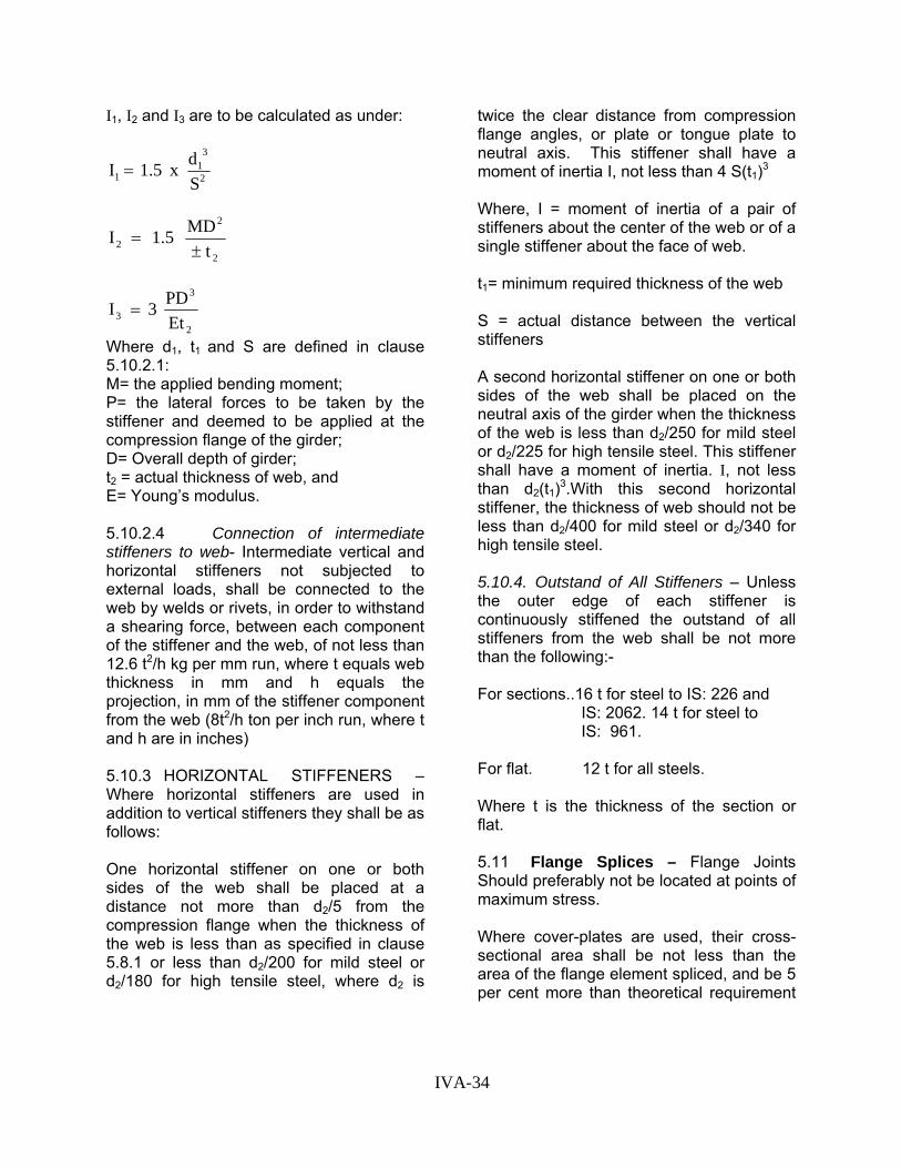
I1, I2 and I3 are to be calculated as under:
2
31
1 Sd x 1.5 I =
2
2
2 tMD 1.5 I±
=
2
3
3 EtPD 3 I =
Where d1, t1 and S are defined in clause 5.10.2.1: M= the applied bending moment; P= the lateral forces to be taken by the stiffener and deemed to be applied at the compression flange of the girder; D= Overall depth of girder; t2 = actual thickness of web, and E= Young’s modulus. 5.10.2.4 Connection of intermediate stiffeners to web- Intermediate vertical and horizontal stiffeners not subjected to external loads, shall be connected to the web by welds or rivets, in order to withstand a shearing force, between each component of the stiffener and the web, of not less than 12.6 t2/h kg per mm run, where t equals web thickness in mm and h equals the projection, in mm of the stiffener component from the web (8t2/h ton per inch run, where t and h are in inches) 5.10.3 HORIZONTAL STIFFENERS – Where horizontal stiffeners are used in addition to vertical stiffeners they shall be as follows: One horizontal stiffener on one or both sides of the web shall be placed at a distance not more than d2/5 from the compression flange when the thickness of the web is less than as specified in clause 5.8.1 or less than d2/200 for mild steel or d2/180 for high tensile steel, where d2 is
twice the clear distance from compression flange angles, or plate or tongue plate to neutral axis. This stiffener shall have a moment of inertia I, not less than 4 S(t1)3 Where, I = moment of inertia of a pair of stiffeners about the center of the web or of a single stiffener about the face of web. t1= minimum required thickness of the web S = actual distance between the vertical stiffeners A second horizontal stiffener on one or both sides of the web shall be placed on the neutral axis of the girder when the thickness of the web is less than d2/250 for mild steel or d2/225 for high tensile steel. This stiffener shall have a moment of inertia. I, not less than d2(t1)3.With this second horizontal stiffener, the thickness of web should not be less than d2/400 for mild steel or d2/340 for high tensile steel. 5.10.4. Outstand of All Stiffeners – Unless the outer edge of each stiffener is continuously stiffened the outstand of all stiffeners from the web shall be not more than the following:- For sections..16 t for steel to IS: 226 and IS: 2062. 14 t for steel to IS: 961. For flat. 12 t for all steels. Where t is the thickness of the section or flat. 5.11 Flange Splices – Flange Joints Should preferably not be located at points of maximum stress. Where cover-plates are used, their cross-sectional area shall be not less than the area of the flange element spliced, and be 5 per cent more than theoretical requirement
IVA-34

of the spliced element and the calculated working stress in the outer covers shall not exceed the allowable working stress in the flange. There shall be enough rivets or bolts on each side of the splice to develop at least the load in the spliced element plus 5 per cent. For design of welds in flange plates in welded construction, provisions of IRS Welded Bridge Code shall apply. 5.12 Splices in Web – Splices in the web of plate girders and rolled sections used as beams shall be designed to resist the shearing forces and the moments in the web at the spliced section. In riveted or bolted construction splice plates shall be provided on each side of the web. 5.13 Lateral Bracing 5.13.1 All spans shall be provided with end cross frames and a lateral bracing system extending from end to end of sufficient strength to transmit to the bearings the wind or seismic, racking and centrifugal forces, if any, as specified in the Bridge Rules. 5.13.2 Deck type spans of over 20 m (or 65 ft) effective span shall be provided with end cross frames and a lateral bracing system between the top flanges, of sufficient strength to transmit to the bearings the total lateral load due to wind, or seismic racking and centrifugal forces and with a lateral bracing system between the bottom flanges of sufficient strength to transmit one-quarter of the total lateral loads. 5.13.3 The lateral bracing between compression flanges of all spans shall in addition be designed to resist a transverse shear at any section equal to 21/2 percent of the total compressive force carried by both the flanges at the section under consideration. Where, however, the transverse sleepers rest directly on compression flanges and offer resistance
against buckling of these flanges, this additional transverse shear may be ignored. Note:- Existing deck type plate girder with transverse sleepers need not be condemned on account of the absence of lateral bracings, provided they show no sign of distress or undue internal oscillations. 6 OPEN WEB GIRDERS 6.1 Intersection at Joints – For triangulated trusses designed on the assumption of pin jointed connections, members meeting at a joint should, where practicable, have their centroidal axes meeting at a point, and wherever practicable the centre of resistance of a connection shall lie on the line of action of the load so as to avoid an eccentricity moment on the connections. Where the design is based on non-intersecting members at a joint, all stresses arising from the eccentricity of the members shall be calculated and the stresses kept within the limits specified in the appropriate clauses of this Code. 6.2 General Requirements for Compression Members 6.2.1 The properties of a section shall be computed from the effective sectional area. When plates are provided solely for the purpose of lacing or battening, they shall be ignored in computing the radius of gyration of the section. 6.2.2 The effective sectional area shall be the gross area less the specified deductions for excessive widths of plates (see clause 5.2.1) and the maximum deductions for open holes, including holes for black bolts (see clause 7.2) occurring in a section perpendicular to the axis of the member.
IVA-35

6.2.3 The ratio of the effective length to the least radius of gyration shall not exceed: 120 for main members, and 140 for wind bracing and subsidiary members. 6.2.4 The maximum unsupported width or projection of any plate forming part of a compression member shall be in accordance with sub clauses 5.2.1.1 and 5.2.1.2.
6.2.5 The open sides of built-up compression members of U or I sections
shall be connected by lacing or battening where the length of the outstand towards the open side exceeds 16 times the mean thickness of the outstand. 6.2.6 Lacing and battening plates shall be designed in accordance with clauses 6.5 and 6.6 and shall be proportioned to resist a total transverse shear force Q at any point in the length of the member equal to at least 21/2 percent of the axial force in the member together with all shear due to external
TABLE XI – EFFECTIVE LENGTH OF COMPRESSION MEMBERS
Effective length l of member
For buckling normal to the plane of the truss
Member
For buckling in the plane of the truss.
Compression chord or compression member effectively braced by lateral system.
Compression chord or compression member unbraced.
Chords
0.85 x distance between centres of intersection with the web members
0.85 x distance between centres of intersection with the lateral bracing members or rigidly connected cross girders.
See clause 6.3.4.
Single triangulated system
0.70 x distance between centres of intersection with the main chords.
0.85 x distance between centres of intersections.
Distance between centres of inter-sections.
Web Multiple intersection system where adequate connections are provided at all points of intersection.
0.85 x greatest distance between centres of any two adjacent intersections.
0.70 x distance between centres of intersection with the main chords.
0.85 x distance between centres of intersection with the main chord
Note: The intersections referred to are those of the centroidal axes of the members.
IVA-36

forces, if any, in the plane of lacing. The shear force Q shall be considered as divided equally among all lacing, battening and plating in parallel lines.
6.2.7 Compression members composed of two or more components connected as described in clauses 6.4.6.5 and 6.6 may be designed as homogenous members.
6.3 Effective Length of Compression Members other than Lacings
6.3.1 In riveted, bolted or welded trusses the compression members act in a complex manner and the effective length to be used in clause 3.8 shall be taken as given in Table XI except that, for battened struts, all value given in table shall be increased by 10 percent.
6.3.2 For single-angle discontinuous struts connected to gussets or to a section either by riveting or bolting by not less than 2 rivets or bolts in line along the angle at each end, or by their equivalent in welding, the eccentricity of the connection with respect to the centroid of the strut may be ignored and the strut designed as an axially-loaded member provided that the calculated average stress does not exceed the allowable stresses given in Tables IV or IV (a), in which l is the length of the strut, centre-to-centre of fastenings at each end, and r is the minimum radius of gyration.
6.3.3 For single angle discontinuous struts intersected by, and effectively connected, to another angle in cross bracing the effective length in the plane of the bracing shall be taken as in Table XI. In the plane normal to the plane of the bracing, the effective length shall be taken as the distance between the points of intersection and the centroids of the main members. In calculating the ratio of slenderness the radius of gyration about the appropriate rectangular axis shall be taken for buckling normal to the plane of the
bracing and the least radius of gyration of buckling in the plane of the bracing.
6.3.4 Effective Length of Unbraced Compression Chords
6.3.4.1 For simply supported trusses with ends restrained at the bearings against torsion the effective length l of the compression chord for buckling normal to the plane of the truss, to be used in the equation given in clause 3.8, shall be taken as follows:
6.3.4.2 With no lateral support to compression chord – where there is no lateral bracing between compression chords and no cross frames, l = span.
6.3.4.3 With compression chord supported by U-frames – Where there is no lateral bracing of the compression chord, but where cross member and verticals forming U-frames provide lateral restraint:
l =2.5 4 δEIa but not less than a Where, δ = the virtual lateral displacement of the compression chord at the frame nearest mid-span of the truss, taken as the horizontal deflection of the vertical member at the point of its intersection with the centroid of the compression chord, under the action of a unit horizontal force applied at this point to the frame only. This deflection shall be computed assuming that the cross member is free to deflect vertically and that the tangent to the deflection curve at the centre of its span remains parallel to the neutral axis of the unstrained cross member. In the case of existing bridges the value of δ should be determined experimentally.
a = distance between frames.
IVA-37

I = maximum moment of inertia of compression chord about the y-y axis of the truss.
E= Young’s modulus.
a) when δ is not greater than a3 / 40E I, l = a
b) In case of symmetrical U-frameswhere cross members and verticalsare each of constant moment ofinertia throughout their own length.
( ) ( )2
2
1
3 ''3
'EI
bdEId
+=δ
where, d’ = distance of the centroid of the compression chord from the top of the cross member.
d” = distance of the centroid of the compression chord from the neutral axis of the cross member.
b = half the distance between centre of the main trusses.
I1 = moment of inertia of the vertical in its plane of bending.
I2 = moment of inertia of the cross member in its plane of bending.
E = Young’s modulus.
U-frames shall have rigid connections and shall be designed to resist, in addition to the effects of wind and other applied forces, the effect of a horizontal force F acting normal to the compression chord of the truss at the level of the centroid of this chord where
1.7) f(C 10 x 1.4 Fac0
-3
−=
/δI
In the above formula
Co = Euler critical stress in the chord
π2 E = ------ (l/r)2
Where, l = has the value 2.5 4 δEIa
fac the calculated working stress in the chord.
δ = the deflection of the chord under the action of unit horizontal force as defined above.
In case of very rigid U-frames where δ is less than a3 / 40 El, the horizontal force F shall be obtained by putting δ = a3 / 40 EI and l =a.
6.3.4.4 With compression chord supporting continuous deck – A compression chord continuously supporting a reinforced concrete or steel deck shall be deemed to be effectively restrained laterally throughout its length (i.e. l=0) if the frictional or positive connection of the deck to the chord is capable of resisting a lateral force, distributed uniformly along its length, of 21/2 per cent of the maximum force in the chord, in addition to other lateral forces.
6.4 Compression Members Composed of Two Components Back-to-Back
6.4.1 Compression members composed of two angles, channels or tees, back-to-back and separated by a distance not exceeding 50 mm (2 in.), shall be connected together by riveting, bolting or welding, so that the maximum ratio of slenderness l/r of each component of the member between such connections is not greater than 50 or 0.5 of the maximum ratio of slenderness of
IVA-38
the member as a whole, whichever is the lesser, where I is the distance between the centres of connections. The number of connections shall be such that the member is divided into not less than three approximately equal parts. 6.4.2 Where the members are separated back to back the rivets or bolts in these connections shall pass through solid washers or packings, and where the connected angles, legs or tables of tees are 127 mm (5 in.) wide or over, or where webs of channels are 152 mm (6 in.) wide or over, not less than two rivets or bolts shall be used in each connection, one on the line of each gauge mark. 6.4.3 Where these connections are made by welding, solid packings shall be used to effect the jointing unless the members are sufficiently close together to permit butt welding, and the members shall be connected by welding along both pairs of edges of the main components. 6.4.4 The rivets, bolts or welds in these connections shall be sufficient to carry the shear forces and the moments specified for battened struts, and in no case shall the rivets or bolts be less than 16 mm (5/8 in.) 6.4.5 Compression members connected by such riveting, bolting or welding shall not be subjected to transverse loading in a plane perpendicular to the riveted, bolted or welded surfaces. 6.4.6 Where the components are in contact back to back riveting, bolting or intermittent welding shall be in accordance with clauses as applicable. 6.5 Lacing of Compression Members
6.5.1 As far as practicable the lacing system shall not be varied throughout the length of the compression member. 6.5.2 Lacing bars shall be inclined at an angle of 500 to 700 to the axis of the member where a single intersection system is used, and at an angle of 40° to 50° where a double intersection system is used. 6.5.3 Except for tie plates as specified in clause 6.5.8 double intersection lacing systems shall not be combined with members of diaphragms perpendicular to the longitudinal axis of the main member, unless all forces resulting from deformation are calculated and provided for in lacing and its fastenings. 6.5.4 Lacing bars shall be so connected that there is no appreciable interruption of the triangulation of the system. 6.5.5 The maximum spacing of lacing bars, whether connected by welding, riveting or bolting, shall be such that the maximum slenderness ratio l/r of the components of the compression member between consecutive connections of the lacing bars to one component is not greater than 50 or 0.7 of the maximum ratio of slenderness of the member as a whole, whichever is the lesser, where l is the distance between the centres of the connections of the lacing bars to one component. 6.5.6 The required section of lacing bars shall be determined by using the permissible stresses for compression and tension members given in clauses 3.7 and 3.8. The ratio l/r of the lacing bars shall not exceed 140. For this purpose, the effective length shall be taken as follows: 6.5.6.1 In riveted or bolted construction – The length between the inner end rivets or bolts of the lacing bar in single intersection
IVA-39
lacing, and 0.7 of this length for double intersection lacing effectively connected at intersections.
6.5.6.2 In welded construction the distance between the inner ends of effective lengths of welds connecting the bars to the components in single intersection lacings, and 0.7 of this length for double intersection lacing effectively connected at intersections.
6.5.7 Lacing bars shall be connected to the main member either by riveting or bolting by one or more rivets for bolts, in line along the lacings or by welding at each end sufficient to transmit the load to the bars. Any eccentricity of the connection with respect to the centroid of the lacing bar may be ignored and the lacing designed as an axially-loaded strut provided that the calculated average stress does not exceed the allowable stress given in Table IV or IV(a). Where welded lacing bars overlap the main component, the amount of lap shall be not less than four times the thickness of the bar or four times the mean thickness of the flange of the component to which the bars are attached, whichever is lesser. Welding shall be provided at least along each side of the bar for the full length of the lap and returned along the ends of the bar for a length equal to at least four times the thickness of the bar. Where lacing bars are fitted between the main components they shall be connected to each component by fillet welds on both side of the bar or by full penetration butt welds.
6.5.8 Laced compression members shall be provided with tie plates at the ends of the lacing systems, at points where the lacing systems are interrupted and where the member is connected to another member.
6.5.9 The length of the end tie plates measured between end fastening along the longitudinal axis of the member shall not be
less than the perpendicular distance between the lines of rivets connecting them to the flanges or the vertical side plates of the main chords, whichever is the greater, and shall be at least equal to the depth of the cross girders where these are directly attached to the struts and the length of intermediate tie plates shall be not less than ¾ of the distance between lines of rivets.
6.5.10 The thickness of the tie plates shall be not less than 1/50 of the distance between the innermost lines of rivets, bolts or welds, except when effectively stiffened at the free edges, in which case the minimum thickness may be 8 mm (5/16 in.) ; for this purpose the edge stiffener shall have a slenderness ratio not greater than 170. 6.5.11 Tie plates and their fastenings (calculated in accordance with the method described for battens) shall be capable of carrying the forces for which the lacing system is designed.
6.6 Battening of Compression Members
6.6.1 Battened compression members shall comply with the following requirements.
6.6.1.1 The battens shall be placed opposite each other at each end of the member and at points where the member is stayed in its length, and shall as far as practicable, be spaced and proportioned uniformly through out. The number of battens shall be such that the member is divided into not less than three bays within its actual length centre to centre of connections.
6.6.1.2 In battened compression members in which the ratio of slenderness about the y-y axis (axis perpendicular to the battens) is not more than 0.8 times the ratio of slenderness about the x-x axis, the spacing
IVA-40

of battens centre to centre of end fastenings shall be such that the ratio of slenderness l/r of the lesser main component over this distance shall be not grater 50 to 0.7 times the ratio of slenderness of the member as a whole, about its x-x axis (axis paralleled to the battens). In battened compression members in which the ratio of slenderness about the y-y axis (axis perpendicular to the battens) is more than 0.8 times the ratio of slenderness about the x-x axis, the spacing of battens centre to centre of end fastenings shall be such that the ratio of slenderness l/r of the lesser main component over that distance shall not be greater than 50 or 0.6 times the ratio of slenderness of the member as a whole about its weaker axis. 6.6.1.3 Battens shall be plates, channels or I sections and shall be riveted, bolted or welded to the main components. Battens and their connections shall be so designed that they resist simultaneously a longitudinal shear force equal to QD/na and a moment equal to QD/2n where: D= the longitudinal distance centre-to-centre of battens. a= the minimum transverse distance between the centroids of rivet or bolt groups , or welding. Q= the transverse shear force as defined in clause 6.2.6. n = the number of parallel planes of battens 6.6.1.4 The length of end batten plates parallel to the axis of the member shall be not less than the perpendicular distance between the lines of rivet connecting them to the flanges or the vertical side plates of the main chord whichever is the greater, and shall be at least equal to the depth of the cross girders where these are directly attached to the struts; and the length of intermediate battens shall be not less than ¾ of the distance between lines of rivets but in no case shall the length of any batten
plate be less than twice the width of the smaller component in the battens. 6.6.1.5 The thickness of batten plates shall be not less than 1/50 of the minimum distance between the innermost lines of connecting rivets, bolts or welds, except when effectively stiffened at the free edges, in which case the minimum thickness may be 8 mm (5/16 in.); for this purpose the edge stiffener shall have a slenderness ratio not greater than 170. 6.6.1.6 The length of weld connecting each longitudinal edge of the batten plate to a component shall in the aggregate be not less than half the length of the batten plate, and at least one-third of the weld shall be placed at each end of the longitudinal edge. In addition, the welding shall be returned along the ends of the plate for a length equal to at least four times the thickness of the plate. Where tie or batten plates are fitted between main component they shall be connected to each component either by fillet welds on each side of the plate, at least equal in length to that specified in the preceding paragraph, or by complete penetration butt welds along the whole length of the plate. 6.6.1.7 Battened compression members not complying with these requirements, or those subjected to bending moments in the plane of the battens shall be designed according to the exact theory of elastic stability, or empirically with verification by tests, so that they have a load factor of not less than 1.7 in the actual structure. 6.6.1.8 Battened compression members composed of two angles forming a cruciform cross section shall conform to the above requirements except as follows:
IVA-41

(a) The battens shall be in pairs placed in contact one against the other unless they are welded to form cruciform battens. (b) A transverse shear force of Q/ 2 shall be taken as occurring separately about each rectangular axis of the whole member. (c) A longitudinal shear force of QD/a 2 and the moment QD/2 2 shall be taken in respect of each batten in each of the two planes, except where the maximum value of l/r can occur about a rectangular axis, in which case each batten shall be designed to resist a shear force of 21/2 percent of the total axial force. Q, D and a are as defined in clause 6.6.1.3.
6.7 General Requirements for Tension Members: 6.7.1 Tension members should preferably be of rigid cross section, and when composed of two or more components these shall be connected as described in clauses 6.8, 6.9 and 6.10.
6.7.2 The properties of the cross section shall be computed from the effective sectional area as given in clause 4.3.2.1.
When plates are provided solely for the purposes of lacing or battening, they shall be ignored in computing the radius of gyration of the section.
6.7.3 For main members the ratio of unsupported length to the least radious of gyration shall not exceed:
(a) 250 for railway bridges, (b) 300 for road and foot bridges.
6.7.4 The open sides of built-up tension members of U or I section shall be connected by lacing and battening , when the length of the outstand, towards the open side, exceeds 16 times the mean thickness of the outstand.
6.7.5 Lacing and battening shall be designed in accordance with clauses 6.9 and 6.10 and shall be proportioned to resist all shear forces due to external forces, if any, in the plane of lacing. The shear shall be considered as divided equally among all transverse systems and plating in parallel planes.
6.7.6 The net sectional area of a bolt or screwed tension rod shall be taken as the area at the root of the thread.
6.8 Tension Members Composed of two Components Back-to-Back
6.8.1 Tension members composed of two angles, tees or channels back-to-back, either in contact or separated by a distance not exceeding 50 mm (2 in.), shall be connected together in their length at regular intervals through solid washes or packing by riveting, bolting or welding so spaced that the maximum ratio of slenderness of each element is not greater than that specified for main members in clause 6.7.3.
6.8.2 Where the components are in contact back-to-back, riveting, bolting or intermittent welding shall be in accordance with clauses applicable.
6.9 Lacing of Tension Members
6.9.1 As far as practicable the lacing system shall not be varied throughout the length of the tension members.
6.9.2 Lacing bars shall be inclined at an angle of 50о to 70о to the axis of the member when a single intersection system is used and at an angle of 40о to 50о when a double intersection system is used.
6.9.3 Except for tie plates as specified in clause 6.9.7 below, double intersection lacing systems shall not be combined with members or diaphragms perpendicular to
IVA-42

the longitudinal axis of the member, unless all forces resulting from deformation of the member are calculated and provided for in the lacing and its fastenings. 6.9.4 Lacing bars shall be so connected that there is no appreciable interruption of the triangulation of the system. 6.9.5 The required section of lacing bars shall be determined by using the permissible stresses for compression and tension members given in clauses 3.7 and 3.8. the ratio l/r of the lacing shall not exceed 170. For this purpose the effective length shall be taken as follows: 6.9.5.1 In riveted or bolted construction, the length between the inner end rivets or bolts of the lacing bar in single intersection lacing and 0.7 times this length for double intersection lacing effectively connected at intersection. 6.9.5.2 In welded construction, the distance between the inner ends of effective lengths of welds connecting the bars to the components for single intersection lacing and 0.7 times this length for double intersection lacing effectively connected at intersections. 6.9.6 The riveting, bolting or welding of lacing bars to the main members shall be sufficient to transmit the load to the bars. Where welded lacing bars overlap the main components, the amount of lap shall be not less than four times the thickness of the bar or four times the mean thickness of the flange of the component to which the bars are attached, whichever is the lesser. The welding shall be provided at least along each side the bar for the full length of the lap and returned along the ends of the plate for a length equal to at least 4 times the thickness of the plate.
6.9.7 Where lacing bars are fitted between main components, they shall be connected to each component by fillet welds on both sides of the bar or by full penetration butt welds. 6.9.8 Laced tension members shall be provided with tie plates at the ends of the lacing systems, at points where the lacing systems are interrupted and where the member is connected to another member. 6.9.9 The length of end batten plates parallel to the axis of the member shall be not less than the perpendicular distance between the lines of rivets connecting them to the flanges or the vertical side plates of the main chords whichever is the greater, and shall be at least equal to the depth of the cross girders where these are directly attached to the struts; and the length of intermediate tie plates shall be not less than ¾ of the distance, between the lines of rivets. 6.9.10 The thickness of all tie plates shall be not less than 1/60 of the distance between the innermost lines of rivets, bolts or welds attaching them to the main components, except when effectively stiffened at the edges, in which case the minimum thickness may be 8 mm (5/16 in.); for this purpose the edge stiffeners shall have a slenderness ratio not greater than 170. 6.10 Battening of Tension Members 6.10.1 Battened tension members shall comply with the following requirements: 6.10.1.1 The spacing of battens, measured as the distance between the middles of adjacent pitches of rivets or bolts or, for welded construction the clear distance between the battens, shall be such that the maximum ratio of slenderness of
IVA-43

each element is not greater than that specified for main members in clause 6.7.3.
6.10.1.2 The effective length of the batten, parallel to the axis of the member, shall be taken as the longitudinal distance between end fastenings.
End battens shall have an effective length of not less than the perpendicular distance between the lines of rivets connecting them to the flanges or the vertical side plates of the main chords, whichever is the greater, and shall be at least equal to the depth of the cross girders where these are directly attached to the struts; and the length of intermediate battens shall have an effective length of not less than one-half of the distance between the lines of rivets.
6.10.1.3 Batten plates shall have a thickness of not less than 1/60 of the minimum distance between the connecting rivet or bolt groups or welds, except where they are stiffened at their edges.
6.10.1.4 Where battens are attached by rivets or bolts, not less than two rivets or bolts shall be used in each connection. Where battens are attached by welds the length of welds connecting each longitudinal edge of the batten plate to the component shall, in the aggregate, be not less than half the length of the batten plate, and at least 1/3 of the weld shall be placed at each end of the longitudinal edge. In addition, welding shall be returned along the base of the plate for a length at least equal to four times the thickness of the plate (But see clause 3.6.5)
Where the tie or batten plates are fitted between main components they shall be connected to each member either by fillet welds on each side of the plate equal in length to at least that specified in the preceding paragraphs or by full penetration butt welds.
6.11 Splices 6.11.1 Compression Members
6.11.1.1 Splices in compression members, located at or near effectively braced panel points, shall be designed to transmit the full load in the member. All other splices in compression members shall have a sectional area 5 per cent more than that required to develop the load in the member at the average working stress in the member. All cover material shall, as far as practical, be so disposed with respect to the cross section of the member as to communicate the proportional load in the respective parts of the section.
6.11.1.2 Both surfaces of the parts spliced shall be covered, or other means taken to maintain the alignment under load of the abutting ends.
6.11.1.3 Where flexural tension may occur in the member, the cover material shall be designed to resist such tension.
6.11.1.4 Rivets, bolts or welds shall develop the full load in the cover material as defined above, calculated on the cover area.
6.11.2 Tension Members
6.11.2.1 Splices in tension members shall have a sectional area 5 percent more than that required to develop the load in the member and, whenever practicable, the cover material shall be disposed to suit the distribution of stress in the various parts of the cross section of the member. Both surfaces of the parts spliced shall be covered wherever possible.
6.11.2.2 Rivets, bolts or welds shall develop the full load in the cover material as defined above, calculated on the cover area.
IVA-44

6.12 Connection at Intersections
6.12.1 Connections of members at an intersection shall develop at least the design loads and moments communicated by the members. Due regard to the nature and distribution of stress over the cross section of the members shall be given in determining the distribution of the fastenings. All members shall, where possible, be so connected that the load is appropriately distributed over the cross section; otherwise, consideration shall be given to the distribution of stress through the material to those parts of the section not directly connected, and for this purpose the angle of distribution may be taken as 45°.
6.12.2 Gusset shall be capable of sustaining the design loads and moments communicated by the members without exceeding the allowable working stresses.
6.12.3 Rivet, bolt and welding groups shall be as compact as practicable.
6.13 Lug Angles
6.13.1 Lug angles connecting a channel or similar member shall, as far as possible, be disposed symmetrically with respect to the section of the member.
6.13.2 In the case of angle members the lug angles, and their connection to the gusset or other supporting member, shall be capable of developing a strength not less than 20 per cent in excess of the force in the outstanding leg of the angle, and the attachment of the lug angles to the angle member shall be capable of developing a strength 40 per cent in excess of that force.
6.13.3 In the case of channel or similar members, the lug angles, and their connection to the gusset or other supporting member, shall be capable of developing a strength not less than 10 per cent in excess
of the force not accounted for by the direct connection of the member, and the attachment of the lug angles to the member shall be capable of developing a strength of 20 per cent in excess of that force.
6.13.4 In no case shall less than two bolts or rivets be used for attaching the lug angle to the gusset or other supporting member.
6.13.5 The effective connection of the lug angle shall, as far as possible, terminate at the end of the member connected, and the fastening of the lug angle to the member shall preferably start in advance of the direct connection of the member to the gusset, etc.
6.14 Section at Pin Holes in Tension Members – In pin-connected tension members the longitudinal net section beyond the pin hole parallel with the axis of the member shall be not less than the required net section of the member. The net section through the pin hole transverse to the axis of the member shall be at least 33 per cent greater than the required net section of the member. In the case of members without stiffened edges the ratio of the net width of the members (through the pin hole transverse to the axis of the member) to its thickness shall be not more than 16. Where the thickness of main material is not sufficient to resist the load from the pin in bearing; or where the net section through the pin hole requires reinforcement, pin plates (see clause 6.15) shall be provided and the total thickness shall comply with the above requirements.
6.15 Pin Plates – Pin plates shall be of sufficient thickness to make up the required bearing or cross-sectional area and shall be so arranged as to reduce the eccentricity to a minimum. Their length measured from the centre of the pin to the end (on the reaction side) shall be at least equal to their
IVA-45
width and at least one plate on each side shall be as wide as the dimensions of the member will allow. Pin plates shall be connected with enough rivets, bolts or welds to transmit the bearing pressure on them and shall be so arranged as to distribute it uniformly over the full section of the member.
6.16 Diaphragms in Members – In addition to diaphragms required for the proper functioning of the structure, diaphragms shall be provided as necessary for fabrication, transport and erection.
6.17 Lateral Bracing 6.17.1 All spans shall be provided with a lateral bracing system extending from end to end of sufficient strength to transmit to the bearings the wind or seismic, racking and centrifugal forces, if any, as specified in the Bridge Rules.
6.17.2 The bracing shall be so designed as to transmit to the main girders the longitudinal loads due to tractive effort and/or braking effect in order to relieve the cross-girders of horizontal bending stresses. The lateral bracing between compression chords shall be designed to resist a transverse shear at any section equal to 2½ per cent of the total compressive force carried by both the chords at the section under consideration. This force should be considered in addition to the wind, centrifugal and racking forces.
6.17.3 Where the depth permits, lateral diagonal bracing shall be fixed between the top chords of main girders of through span of sufficient rigidity to maintain the chords in line and of sufficient strength to transmit the wind or seismic forces to the portal bracing between the end posts.
6.18 Sway Bracings – The overhead cross bracings, or sway bracings between vertical web members shall be proportioned
to transmit to the lower chords, through the web members, at least 50 per cent of the top panel wind or seismic load, and the vertical web members shall be designed to resist the resulting bending moments.
6.19 Portal Bracing – Portal bracing with knee braces, as deep as clearances will allow, shall be fitted to the end posts or rakers. The portal system at each end, i.e., the end posts or rakers together with the portal bracing, shall be designed to transmit to the bearings one half of the sum of the lateral forces on the top chords. The sway bracing so provided shall not be taken as affording any relief to the lateral bracing system or portal system. In addition, the portal system shall be designed to resist a lateral shear equal to 1¼ per cent of the total compressive force in the two end posts or in the two top chords in the end panel whichever is greater.
7. RIVETING, BOLTING AND WELDING
7.1 Effective Diameter and Bearing Area of Rivets, Bolts and Pins 7.1.1 In calculating the number of rivets, bolts or pins required, the effective diameter shall be taken as : For rivets – the diameter of the hole.
For bolts and pins – the diameter of the bolt or pin.
Rivets, bolts or pins in double shear shall be considered as having twice the shear area of those in single shear.
7.1.2. The effective bearing area of a pin, rivet or bolt shall be the diameter multiplied by the thickness of the part transmitting or receiving the load, except that for rivets or bolts with countersunk heads half the depth of the countersunk shall be ignored in arriving the length in bearing.
7.2 Deductions for Holes for Rivets, Bolts and Pins - In calculating the area to be deducted for rivets, bolts or pins, the
IVA-46

diameter of the hole and for the countersunk bolts or rivets, the diameter of the hole plus 3 mm (1/8 in.) shall be used. 7.3 Minimum Pitch of Rivets and Bolts The distance between centres of rivets or bolts shall be not less than 2½ times the nominal diameter of the rivet or bolt. 7.4 Maximum Pitch of Rivets and Bolts 7.4.1 The distance between centres of any two adjacent rivets or bolts connecting together elements in contact of compression or tension members shall not exceed 32 t or 300 mm (12 in.), whichever is the lesser, where t is the thickness of the thinner outside element. 7.4.2 The distance between centres of two adjacent rivets or bolts in a line lying in the direction of stress shall not exceed 16 t or 200 mm (8in.), in tension members, or 12 t or 200 mm (8 in.) whichever is the lesser, in compression members. In the case of compression members in which forces are transferred through butting faces this distance shall not exceed 4½ times the diameter of the rivets or bolts for a distance from the abutting faces equal to 1½ times the width of the member. 7.4.3 The distance between centres of any two consecutive rivets or bolts in a line adjacent to and parallel to an edge of an outside plate shall not exceed 100 mm (4 in.) plus 4 t or 200 mm (8 in.), whichever is the lesser in compression or tension member. 7.4.4 When rivets or bolts are staggered at equal intervals and the gauge does not exceed 75 mm (3 in.) the distances between centres of rivets or bolts, as specified in clauses 7.4.2 and 7.4.3 above, may be increased by 50 per cent.
7.5 Edge Distance 7.5.1 The minimum distance from the centre of any rivet hole or bolt hole to a sheared edge or hand flame cut shall be 1¾ times the diameter of the hole and to a rolled, machine flame cut, sawn or planed edge, 1½ times the diameter. 7.5.2 Where two or more parts are connected together a line of rivets or bolts shall be provided at a distance of not more than 4 t + 40 mm (1½ in.) from the nearest edge, where t is the thickness of the thinner outside plate. 7.6 Hand Driven Rivets – The use of hand driven rivets shall be avoided as far as possible. If unavoidable, the number of rivets to be provided shall be determined in accordance with clause 3.7 (Table II). 7.7 Rivets or Bolts Through Packing – The number of rivets or bolts transmitting shear through packing shall be increased above the number required by normal calculations by 1¼% for each millimetre (2% for each 1/16 in.) thickness of packing except that for packing having a thickness of 6 mm (¼") or less, no increase shall be made. For double shear connections packed on both sides, the number of additional rivets or bolts required shall be determined from the thickness of the thicker packing. The additional rivets or bolts should be placed in an extension of the packing. NOTE :- If the packing is made of more than one plate, placed side by side, the thickness of packing shall be the over-all thickness of all such plates placed together. 7.8 Long Grip Rivets – The grip of rivets carrying calculated loads shall not exceed 8 times the diameter of the hole.
IVA-47

Where the grip exceeds 6 times the diameter of the hole, the number of rivets required by normal calculation shall be increased by not less than half a percent for each additional millimetre of grip (¾% for each additional 1/16" of grip).
7.9 Rivets in Tension – The use of rivets in tension should be avoided wherever possible, but if their use is unavoidable, the stress shall not exceed that specified in clause 3.7.
7.10 Bolts – Turned and fitted, precision, semi precision and black bolts, when provided, shall conform to IRS B-I. Where there is risk of nuts becoming loose they shall be secured by check nuts or any other suitable means.
7.11 General Requirements for Welds – The design of welds in mild steel shall be in accordance with the requirements of the IRS Welded Bridge Code.
IVA-48

7.12 High Strength Friction Grip (HSFG) Bolts - High Strength Friction Grip (HSFG) bolts shall be provided as per para 28.9 of IRS Specification For Fabrication And Erection Of Steel Girder Bridges And Locomotive Turn Tables (Fabrication Specification) Serial No. B1-2001. These bolts shall be designed as per provisions of IS:4000-1992 (High Strength Bolts in Steel Structures - Code of Practice) with the following over-riding clauses:
7.12.1 Provisions not covered in IS:4000-1992 shall conform to IRS Codes. For edge distance, gauge distance and pitch etc., provisions of para 7 shall be followed.
7.12.2 Joints with HSFG bolts shall be designed only as friction type joints. Bearing type joints with HSFG bolts shall not be provided.
7.12.3 Short/long slotted holes shall not be allowed.
7.12.4 The diameter of hole shall be 1.5 mm more than the nominal diameter of the HSFG bolt for bolt dia less than 25mm and 2mm more than the nominal diameter of the HSFG bolt for larger diameters.
7.12.5 In certain cases, HSFG bolts might be required to be provided in oversize holes. The maximum size of oversize holes shall not exceed 1 .25 d or d + 4 mm, whichever is less where d is nominal diameter of HSFG bolt
7.12.6 Design of Friction type joint shall be done as follows:
7.12.6.1 For joints subjected to shear force only -
shear force applied should not exceed
Minimum Bolt Tension shall be as given in table XII below:
Nominal size of Bolt
Minimum Bolt tension In KN Property class 8.8 Property class 10.9
M16 94.5 130 M20 147 203 M22 182 251 M24 212 293 M30 337 466 M36 490 678
Table XII (Based on Table 3 of IS:4000-1992) 7.12.6.2 For joints subjected to shear and tensile force –
where factor F shall be taken as 2.0 if external tension is repetitive and 1.7 if non repetitive. Proof Load shall be worked out for the yield stress of the bolt used and the stress area of thread as given in Table 2 of IS:4000-1992.
7.12.6.3 In 7.12.6.1 and 7.12.6.2, the factor of safety shall be taken as follows:
48/A
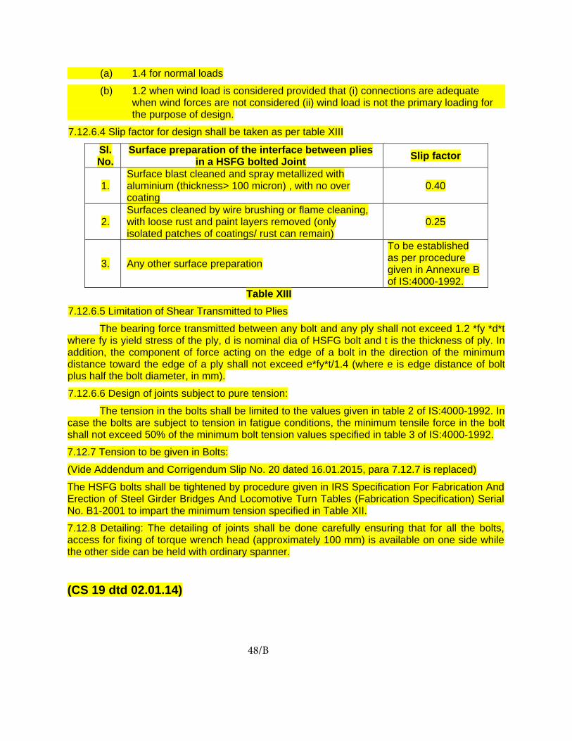
(a) 1.4 for normal loads
(b) 1.2 when wind load is considered provided that (i) connections are adequate when wind forces are not considered (ii) wind load is not the primary loading for the purpose of design.
7.12.6.4 Slip factor for design shall be taken as per table XIII
Sl. No.
Surface preparation of the interface between plies in a HSFG bolted Joint Slip factor
1. Surface blast cleaned and spray metallized with aluminium (thickness> 100 micron) , with no over coating
0.40
2. Surfaces cleaned by wire brushing or flame cleaning, with loose rust and paint layers removed (only isolated patches of coatings/ rust can remain)
0.25
3. Any other surface preparation
To be established as per procedure given in Annexure B of IS:4000-1992.
Table XIII 7.12.6.5 Limitation of Shear Transmitted to Plies
The bearing force transmitted between any bolt and any ply shall not exceed 1.2 *fy *d*t where fy is yield stress of the ply, d is nominal dia of HSFG bolt and t is the thickness of ply. In addition, the component of force acting on the edge of a bolt in the direction of the minimum distance toward the edge of a ply shall not exceed e*fy*t/1.4 (where e is edge distance of bolt plus half the bolt diameter, in mm).
7.12.6.6 Design of joints subject to pure tension:
The tension in the bolts shall be limited to the values given in table 2 of IS:4000-1992. In case the bolts are subject to tension in fatigue conditions, the minimum tensile force in the bolt shall not exceed 50% of the minimum bolt tension values specified in table 3 of IS:4000-1992.
7.12.7 Tension to be given in Bolts:
(Vide Addendum and Corrigendum Slip No. 20 dated 16.01.2015, para 7.12.7 is replaced)
The HSFG bolts shall be tightened by procedure given in IRS Specification For Fabrication And Erection of Steel Girder Bridges And Locomotive Turn Tables (Fabrication Specification) Serial No. B1-2001 to impart the minimum tension specified in Table XII.
7.12.8 Detailing: The detailing of joints shall be done carefully ensuring that for all the bolts, access for fixing of torque wrench head (approximately 100 mm) is available on one side while the other side can be held with ordinary spanner.
(CS 19 dtd 02.01.14)
48/B

APPENDIX ‘A’ Rules for Pre-stressing Open Web Girder Spans
A-1 PREPARATION OF CAMBER DIAGRAM A-1.1 Contract drawings are dimensioned for the main girder without camber and in order to ensure that its fabrication and erection shall be such as to eliminate deformation stresses in the loaded span, a camber diagram shall be prepared on which shall be clearly indicated the amounts by which the nominal lengths (i.e., the lengths which will give no camber) of members shall be increased or decreased in order that the outline of the girder under full load (dead load, live load and impact) in the case of pre-stressed girders or under full dead load plus 75 per cent of the live load without impact in the case of un-pre-stressed girders, shall be the nominal outline, enlarged (1 + K) times in the case of a through span and reduced (1 – K) times in the case of a deck span (see paragraph 4 below for definition of K).
A-1.2 The stress camber shall be calculated on gross area of the member and be equal to the change of the length of the member due to loading given in para A-1.1, but of opposite sign.
A-1.3 For the purpose of calculating the change in length of members under stress, the modulus of elasticity for both high tensile and mild steels shall be taken as 21,100-kg/sq mm (13,400 ton / sq. in.). The effective length shall be taken between the theoretical intersection points of adjacent members.
A-1.4 To ensure that the length of the floor system of a span shall be constructed to its nominal dimensions, i.e., to avoid changes in lengths of floor and loaded chord lateral system a further change in length shall be made in the lengths of all members equal to
( )KxL x
=memberofLength
lengthchordLoadedncontractioorextensionchordLoaded
In through spans this change will be an increase in the lengths of all members while in the case of deck spans it will be a decrease in the lengths of all members.
A-1.5 The nominal girder lengths altered in accordance with paragraphs 1.2 and 1.4 give a girder correctly stress cambered but with the loaded chord length identical with that shown on the contract drawings, thus requiring no modifications to floor and loaded chord lateral systems.
A-1.6 The nominal lengths and camber lengths shall be rounded off to the nearest half a millimeters (1/64 in.).
A-1.7 The difference between nominal lengths and camber lengths thus modified is the practical camber change.
A-1.8 A williot diagram shall be drawn for the practical camber changes to obtain ordinates of the erection packing necessary to produce the required camber.
A-1.9 Adjustments of the lengths shall be made to top lateral bracing members to suit camber lengths of the top chords in the case of through girder spans and to the bottom lateral bracing members in the case of deck spans. The average value of the pre-stressed length of top or bottom lateral members as the case may be, adopted throughout.
A-2 FABRICATON A-2.1 The actual manufactured lengths of the members are to be the lengths “with camber” given on the cambered diagram.
A-2.2 The positions and angular setting out lines of all connection holes in the main
IVA-49
gussets and also the positions of the connection holes in the chord joints and the machining of the ends shall be exactly as shown on the contract drawings. This will permit the butts in the chord segments to be exactly as shown on the contract drawings.
A-2.3 The groups of connection holes at the ends of all the members are to be as shown on the contract drawings, i.e., without any allowance for camber but the distance between the groups at the ends of each member shall be altered by the amount of the camber allowance in the member.
A-3 ERECTION A-3.1 The joints of the chords shall be drifted, bolted and preferably riveted to their geometric outline.
A-3.2 All other members are to be elastically strained into position by external forces, so that as many holes as possible are fair when filled with rivets.
A-3.3 Drifting of joints shall be avoided as far as possible, and when necessary, should be done with great care and under close expert supervision. Hammers not exceeding one kg. (2 lb.) in weight should be used with turned barrel, drifts and a number of holes drifted simultaneously, the effect of the drifting being checked by observation of adjacent unfilled holes.
A-3.4 The first procedure during erection consists of placing camber jacks in position on which to support the structure. The camber jacks should be set with their tops level and with sufficient run out to allow for lowering of panel points except the centre by the necessary amounts to produce the required camber in the main girders. It is essential that the camber is accurately maintained throughout the process of erection and it should be constantly checked. The jacks shall be spaced so that
they will support the ends of the main girders and the panel points. The bottom chord members shall then be placed on the camber jacks, carefully levelled and checked for straightness and the joints made and riveted up.
A-3.5 The vertical and diagonal web members, except the end posts, shall then be erected in their proper positions on the bottom chords. It is recommended that temporary top gussets, the positions of the holes in which are corrected for the camber change of length in the members, should be used to connect the top ends of the members; this will ensure that the angles between the members at the bottom joints are as given by the nominal outline of the girders. The verticals and diagonals shall then be riveted to the lower chords.
A-3.6 All panel points, except the centre, shall now be lowered by amounts to produce the correct camber in the main girders as shown on the camber diagram.
A-3.7 The top chord should be erected piece-by-piece working symmetrically from the centre outwards, and the joint made by straining the members meeting at the joint and bringing the holes into correct registration. A-3.8 The temporary gussets, if used, shall be replaced by the permanent gussets in the same sequence as the erection of the top boom members.
A-3.9 The end posts shall be erected last. The upper end connection should preferably be made first and if there is no splice in the end raker, the final closure made at the bottom end connection. If there is a splice, the final closure should be made at the splice.
A-3.10 When cantilevered method of erection is used, the above procedure does not apply.
IVA-50
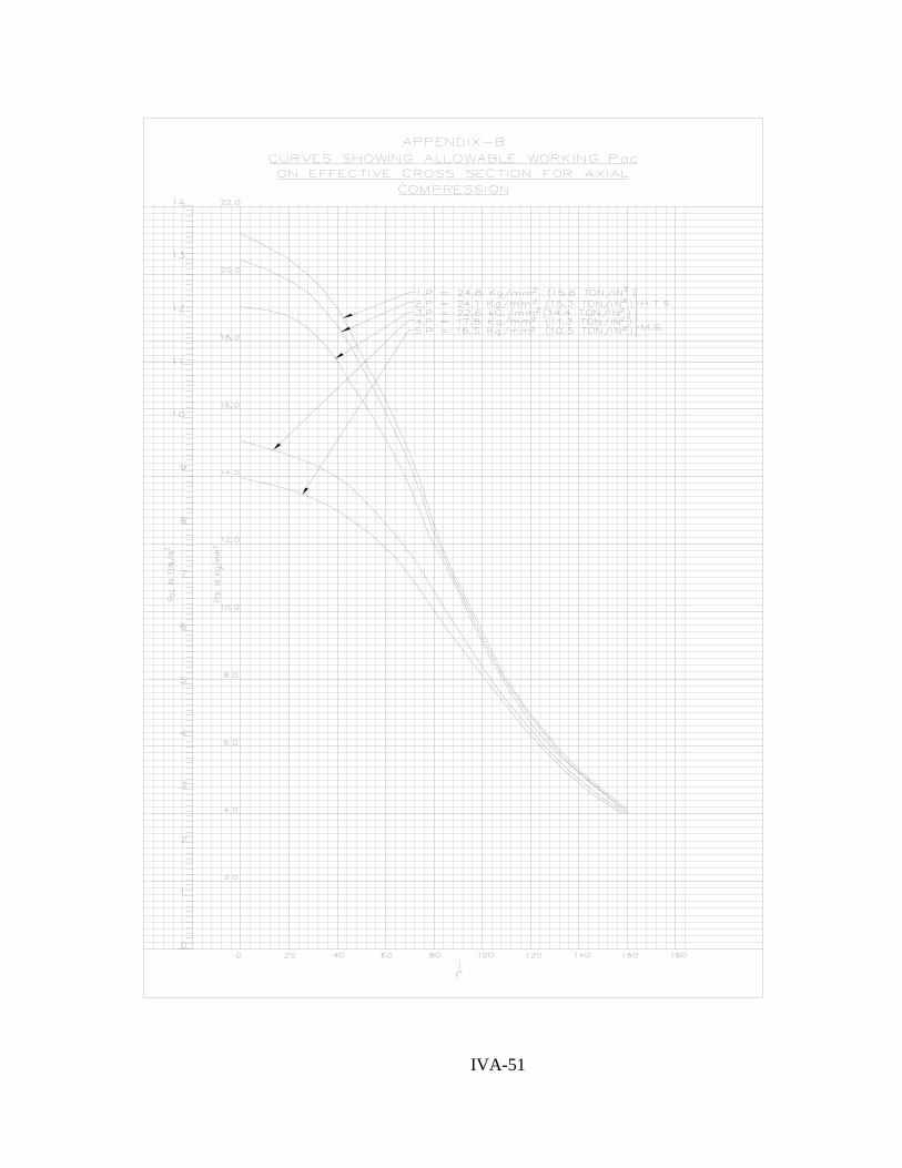
IVA-51

APPENDIX ‘C’ Critical Compression Stress Csfor Sections Symmetrical
About the XX-Axis Formula
C-1. The critical compression stress Cs for sections symmetrical about the x-x axis may be calculated from:
Cs= lZ x
π
⎭⎬⎫
⎩⎨⎧
+ )1( 2
2
GKlWGKEI y π
μZх = gross section modulus about x –x axis.
l = effective length of compression flange.
x
yx
III
μ−
=
Ix = moment of inertia of the whole section about x-x axis. Iy = moment of inertia of the whole section about y-y axis. E = Young’s modulus taken as 21100 kg/mm2 (13400 tons/in.2) G = Modulus of rigidity taken as 0.4E. K = Appropriate torsion constant.
W = warping constant = 2hEI 2
f for
I sections. h = distance between flange centroids. If = moment of inertia of the compression flange only about y-y axis of the girder.
C-1.1 For I sections this formula reduces to
lZC
xs
42200=
⎪⎭
⎪⎬⎫
⎪⎩
⎪⎨⎧
+ )3.121( 2
2
KlhIKI fy
μkg / mm2
to obtain C s in tons/in2, replace the constant 42200 in the above formula by 26800 for sections composed of approximately rectangular elements:
∑ ⎟⎟⎠
⎞⎜⎜⎝
⎛=
3btK
3
approximately, where b and t
are the breadth and average thickness of each element.
C-1.2 For channel and Z sections, the formula in C-1.1 above gives conservative values
C-1.3 For box members, conservative values of Cs are obtained by substituting in formula in C-1.1 above.
K = ( )∑ S/t4A 2
approximately
A = total enclosed area of section. S = length of each element of the periphery. t = thickness of each element (in the case of curtailed flanges, the effective thickness). e.g. for a box of depth d, width b, and uniform thickness t.
bdtd2b K
22
+= approximately.
C-1.4 For a plate or flat in bending in a plane parallel to its surface (substituting appropriate values of K, etc.).
22
2 kg/mm /Dt42200 C =
Or 2
2
2 ton/in /Dt26800 C =
Where, t = thickness D= depth, l = effective length of part in compression.
IVA-52


APPENDIX ‘D’ Method of Computing Permissible Stresses in Existing Wrought
Iron or Early Steel Girder
D-1.1 In the case of early steel girders over which it is desired to run loads causing stresses in excess of those laid down in Clause 3.19 or where there is any doubt as to the quality of the material, the following tests should be made.
D-1.2 Test-pieces shall be cut from representative members carrying direct stress and the permissible stress shall be based on the results of tensile, tests made on these.
D-1.3 For open web spans 20 pieces of metal shall be cut from at least 4 different sections of one or more spans.
D-1.4 For plate web spans 8 pieces shall be cut from at least 4 different sections of one or more spans.
D-1.5 It should be ascertained from rolling marks on the metal whether the material for all the spans in a particular bridge is from the same source and, if possible, rolled in the same year. If this is not the case, the number of pieces of metal indicated above shall be obtained for each different source of supply of the material.
D-1.6 Test-pieces should, if possible, conform to Indian standard tensile test-pieces but it shall be permissible to use test-pieces of smaller size or miniature test-pieces, if desired, provided the elongation is measured on the appropriate gauge length.
D-1.7 In the case of abnormally low-test values, it shall be permissible to repeat the test on two additional specimens cut from the same position and to substitute the lower of the two additional results for the original one.
D-1.8 The permissible working stress in tension f in kg/ sq. mm (T/sq.in.) shall be determined by the following formula:
1.907)percentage Elongation - (10 -
3stress Ultimate f =
[For FPS units:
3)percentage Elongation - (10 -
3stress Ultimate f =
subject to a maximum value of 3
stress Ultimate
The above-mentioned formula shall be applied to each individual test and the permissible stress (f ’) shall be the average of the worst 50% of the results thus obtained. Note:- The value of permissible working stress in tension ( f ’ ) thus obtained shall be subject to a maximum limit of 14.2 kg/sq mm (9.0T/sq in.) in the case of early steel and 9.5 kg/sq mm (6.0T/sq.in.) in the case of wrought iron.
D-1.9 When the permissible working stress in tension (f’) as determined in accordance with para D-1.8, lies between 9.5 kg/sq mm and 14.2 kg/sq mm (6.0T/sq in. and 9.0 T/sq. in.) in the case of early steel, the permissible stress in compression, shear, etc should be arrived at by modifying the respective percentages shown in clause 3.18 in the manner indicated below:-
)5.92.14()5.9
−−
+='
1 (f p)-(100 p p
⎥⎦
⎤⎢⎣
⎡ −+=
6) - (96) (f p) - (100 p p : units FPS For
' 1
IVA-53

where p1 is the modified percentage, and p is the percentage indicated in clause 3.18.
D-1.10 When the permissible working stress in tension (f’) determined in accordance with D-1.8 is less than 9.5 kg/sq. mm (6.0T/sq.in.) the permissible stresses in compressions, shear, etc. for both wrought iron and early steel, shall be obtained by multiplying the respective percentages shown in clause 3.18 by the factor f ’/9.5 (f ’/6 for FPS units).
IVA-54

APPENDIX ‘E’ Method of Computing Stresses in Rivets at the Ends of Existing Plate Girders.
E-1.1 The end shear due to dead load, live load and impact having been calculated, a parabola of bending moment due to a load equal to twice the end shear should be constructed on a base equal to the effective length of the span and from this the curve of flange force should be plotted, using the effective depth of the girder at the various points in the span.
E-1.2 If the web is in one length or, if jointed, is adequately covered for resisting bending force, the curve of flange stress may be reduced in the ratio of:
8W a
a
+
Where, a = gross area of one flange, and W = gross area of web.
E-1.3 A tangent should then be drawn to the curve of flange force, starting from the first rivet at extreme end of girder and the force (S) at the tangent point (X) ascertained. Then the number of rivets (N) required for the flange force increments in the length L between the first rivet and point x will be :-
L RS N+
= and the pitch required will be
NL Ph =
Where R= bearing value of a rivet,
F= assumed friction value for a rivet, viz.,
for a 25 mm (1 in.) dia rivet F = 1.27 tonnes (1.25 ton). for a 22 mm (7/8 in.) dia rivet F = 1.01 tonnes (1.0 ton) and for a 19 mm (¾ in.) dia rivet F = 0.76 tonnes (0.75 ton).
E-1.4 Beyond X the number of rivets required in any length L, equal to 1/12th effective span will be:-
NL P and
F RS N h =+
=
Where: S represents the increase in flange force in the length, L beyond the flange force previously dealt with.
E-1.5 If there is vertical load of W per unit length on the rivets, the required pitch (P v) for this load will be:-
WF R Pv
+=
And the final resultant pitch required will be
⎪⎭
⎪⎬⎫
⎪⎩
⎪⎨⎧
+=
P P
P x P P2
h2
v
vh
IVA-55

1
NEW APPENDIX - G

2
Appendix ‘G’
(Revised)
Fatigue Assessment For Steel Bridges
1. General
“The process of progressive localized permanent structural change occurring in a material
subjected to conditions which produce fluctuating stresses and strain at some point or points
and which may culminate in cracks or complete fracture after a sufficient number of
fluctuations.”
The above definition of fatigue implies that fatigue in materials is the phenomenon which
causes failure of any structural member, under the action of repetitive loads, to take place at
stress levels that are substantially less than those associated with failure under static loading
conditions. Railway bridges are dynamically loaded structures which are subjected to complex
fluctuating loads of varying amplitudes. Therefore, an assessment for fatigue is required to be
made if the bridges are to be designed for a definite service life.
2. Scope
2.1. This document supersedes the provisions in the IRS Steel Bridge Code (1962) with regards to Fluctuations of Stress (Fatigue).
2.2. The fatigue assessment shall be deemed to apply to structures which comply with all applicable codes of practice or regulations and have been analyzed and designed in accordance with accepted principles and practices.
2.3. The structural materials and fabrication procedures shall be deemed to comply with all applicable codes of practice or regulations.
2.4. This document is restricted in scope to the assessment of adequacy of members, connections and joints of railway bridges subjected to fatigue loading for a specified design life.
2.5. The assessment procedure contained herein shall be applicable to all grades of structural steel, conforming to applicable codes of practice or regulations.
2.6. The assessment procedure will not be applicable to the following :- (a) Corrosion fatigue (b) Low cycle(high stress) fatigue (c) Thermal fatigue (d) Stress corrosion cracking (e) High temperatures > 150o C (f) Low temperatures ( brittle transition temperature) (g) Aerodynamically induced vibrations

3
3. Basis
The assessment for fatigue performance is based on Palmgren-Miners’ law and shall be
conducted by either of the following:
(a) the evaluation of the accumulated damage, or
(b) the evaluation of the equivalent constant amplitude stress range which would cause the
same damage for 2 million cycles of application.
The assessment shall also be based on a classification of structural detail or connection
depending upon their fatigue strength. The design stress range corresponding to 2 million
cycles are given for each fatigue class. The provisions for the adequacy of a structural
connection or detail shall be complied with, at each critical location of the structure subjected
to cyclic loading, considering relevant number of cycles and magnitudes of stress ranges
expected to be experienced at the location during the design life of the structure.
4. Terms and definitions
4.1. General
4.1.1 Fatigue The phenomena of damage in a structural part through crack initiation and/or
gradual crack propagation caused by repeated stress fluctuations.
4.1.2 Nominal stress The stress in the parent material or in a weld adjacent to a potential crack location
calculated in accordance with elastic theory excluding all stress concentration
effects. The nominal stress as specified can be a direct stress, a shear stress, a
principal stress or an equivalent stress as appropriate unless explicitly specified.
4.1.3 Modified nominal stress A nominal stress multiplied by an appropriate stress concentration factor kf, to allow
for a geometric discontinuity that has not been taken into account in the
classification of a particular constructional detail.
4.1.4 Geometric stress (hot spot stress) The geometric stress is the maximum principal stress in the parent material
adjacent to the weld toe, taking into account stress concentration effects due to the
overall geometry of a particular constructional detail. Local stress concentration
effects e.g. from the weld profile shape are already included in the detail categories
and need not be considered separately.
4.1.5 Residual stress Residual stress is a permanent state of stress in a structure that is in static
equilibrium and is independent of any applied action. Residual stresses can arise
from rolling stresses, cutting processes, welding shrinkage or lack of fit between
members or from any loading event that causes yielding of part of the structure.
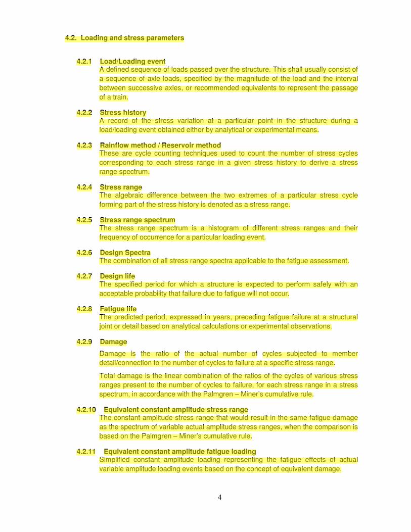
4
4.2. Loading and stress parameters
4.2.1 Load/Loading event A defined sequence of loads passed over the structure. This shall usually consist of
a sequence of axle loads, specified by the magnitude of the load and the interval
between successive axles, or recommended equivalents to represent the passage
of a train.
4.2.2 Stress history A record of the stress variation at a particular point in the structure during a
load/loading event obtained either by analytical or experimental means.
4.2.3 Rainflow method / Reservoir method These are cycle counting techniques used to count the number of stress cycles
corresponding to each stress range in a given stress history to derive a stress
range spectrum.
4.2.4 Stress range The algebraic difference between the two extremes of a particular stress cycle
forming part of the stress history is denoted as a stress range.
4.2.5 Stress range spectrum The stress range spectrum is a histogram of different stress ranges and their
frequency of occurrence for a particular loading event.
4.2.6 Design Spectra The combination of all stress range spectra applicable to the fatigue assessment.
4.2.7 Design life The specified period for which a structure is expected to perform safely with an
acceptable probability that failure due to fatigue will not occur.
4.2.8 Fatigue life The predicted period, expressed in years, preceding fatigue failure at a structural
joint or detail based on analytical calculations or experimental observations.
4.2.9 Damage
Damage is the ratio of the actual number of cycles subjected to member
detail/connection to the number of cycles to failure at a specific stress range.
Total damage is the linear combination of the ratios of the cycles of various stress
ranges present to the number of cycles to failure, for each stress range in a stress
spectrum, in accordance with the Palmgren – Miner’s cumulative rule.
4.2.10 Equivalent constant amplitude stress range The constant amplitude stress range that would result in the same fatigue damage
as the spectrum of variable actual amplitude stress ranges, when the comparison is
based on the Palmgren – Miner’s cumulative rule.
4.2.11 Equivalent constant amplitude fatigue loading Simplified constant amplitude loading representing the fatigue effects of actual
variable amplitude loading events based on the concept of equivalent damage.

5
4.2.12 Fatigue loading The fatigue loading means a set of specific train loads and their daily frequency
indicating the traffic density in terms of GMT (Gross million tonnes per annum). The
traffic load models will consist of a combination of trains to which the bridge may be
subjected within a specified time frame, usually specified by the passage of trains
on a daily basis.
4.3. Fatigue strength
4.3.1 Fatigue strength curve (S – N curve) The fatigue strength curve or the S-N curve is a logarithmic relationship between a
stress range and the cycles to failure at that particular stress range based on the
category of the detail under consideration. The S-N curves are defined separately
for each detail category and may be modified in accordance with other provisions
as applicable.
4.3.2 Detail category The designation given to a particular structural detail for a given direction of stress
fluctuation to indicate which fatigue strength curve is applicable for fatigue
assessment. This is denoted by a number which represents the magnitude in
N/mm2 of the stress range which is associated with an endurance of 2 million cycles
for that particular category.
4.3.3 Reference fatigue strength The reference fatigue strength for a structural detail or connection is the magnitude
in N/mm2 of the constant amplitude stress range (direct or shear as applicable)
associated with an endurance of 2 million cycles.
4.3.4 Constant amplitude fatigue limit The constant amplitude fatigue limit is the limiting magnitude of the stress range
(direct or shear, as applicable) below which no fatigue damage is deemed to accrue
for constant amplitude loading of that particular detail. Under variable amplitude
stresses all stress ranges must be below this limit for no fatigue damage to occur.
4.3.5 Cut off limit The limiting value of the stress range, below which, the stress ranges do not
contribute to the accumulated damage in variable amplitude stress conditions.
4.3.6 Limiting Stress Range The limiting stress range for a particular structural connection or detail is the stress
range for that particular detail category which corresponds to an endurance of
10000 cycles. If either the constant amplitude stress range or any of the variable
amplitude stress ranges (direct or shear as applicable) exceed the limiting stress
range then the provisions contained herein will not be applicable.
4.3.7 Endurance Endurance is the duration of life to fatigue failure, expressed in cycles under the
action of a constant amplitude stress history.

6
5. List of symbols
Symbol Definition
∆∆∆∆σσσσ Stress range(direct stress)
∆∆∆∆ττττ Stress range(shear stress)
∆∆∆∆σσσσE , ∆∆∆∆ττττE Equivalent constant amplitude stress range related to nmax
∆∆∆∆σσσσE,2 , ∆∆∆∆ττττE,2 Equivalent constant amplitude stress range related to 2 million cycles
∆∆∆∆σσσσC , ∆∆∆∆ττττC Reference value of the fatigue strength at NC = 2 million cycles
∆∆∆∆σσσσD , ∆∆∆∆ττττD Fatigue limit for constant amplitude stress ranges at ND = 5 million cycles, unless
otherwise specified
∆∆∆∆σσσσL , ∆∆∆∆ττττL Cut off limit for stress ranges at NL = 100 million cycles
∆∆∆∆σσσσSL , ∆∆∆∆ττττSL Limiting stress range for a detail category at 10000 cycles
∆∆∆∆σσσσC,red reduced reference value of the fatigue strength
γγγγFf Partial safety factor for equivalent constant amplitude stress range ∆∆∆∆σσσσE , ∆∆∆∆ττττE
γγγγMf Partial safety factor for fatigue strength ∆∆∆∆σσσσC , ∆∆∆∆ττττC
m Slope of fatigue strength curve
λλλλi Damage equivalence factors
ΦΦΦΦ Dynamic impact factor
log logarithm to the base 10
ks Reduction factor for fatigue stress to account for size effects
kf stress concentration factor
NR (or N) design life expressed as number of cycles related to a constant stress range i.e.
∆∆∆∆σσσσR or ∆∆∆∆ττττR .
Note: Other symbols occurring in text do not conform to universally accepted nomenclature and
are defined wherever they first occur.

7
6. Fatigue loads
6.1. The fatigue loading specified in this section shall be used for the determination of stresses at critical locations of the railway bridge, by appropriate and accepted methods of analysis. The stresses so determined will form the basis of fatigue assessment of the detail or connection in accordance with Palmgren Miner’s rule.
6.2. The trains comprising the fatigue load models shall be in accordance with Bridge Rules prevailing, unless otherwise specified.
6.3. The recommended traffic models for MBG standard to be adopted for the specification of the fatigue loads shall be in accordance with Table - 6.1
6.4. The recommended traffic models for HM routes to be adopted for the specification of the fatigue loads shall be in accordance with Table - 6.2
6.5. The recommended traffic models for standard 25 t loading -2008 to be adopted for the specification of the fatigue loads shall be in accordance with Table - 6.3
6.6. The recommended traffic models for standard 32.5 t loading (DFC Loading) to be adopted for the specification of the fatigue loads shall be in accordance with Table -6.4
6.7. Other traffic models, in addition to the above or any modification thereof, may be considered as specified by the competent authority.
6.8. In case of bridges with multiple tracks, it is recommended that ;
(a) The train load shall be applied on a track which produces the greatest stress at the detail under consideration.
(b) 15%, unless otherwise specified, of the train loads scaled in magnitude shall be applied on any other track so as to produce the greatest stress at the detail under consideration.
(c) The train and its scaled counterpart, as described in (b) above shall be assumed to move in phase in the same direction.
6.9. In general, the fatigue assessment, shall be conducted in accordance with 12.5 using either the actual train loads or their recommended equivalents in accordance with the Bridge Rules. The loaded length, for simplified analysis, is that length of the span which will give the maximum stress in the structural member or connection, when loaded by an equivalent uniformly distributed load.

8
Table 6.1(a) Traffic Models for MBG Standard
Type of
Train
Tra
in N
o.
Train
Composition
Weight
per
Train (t)
GMT
per
Train
Class of Traffic
Heavy Freight
Traffic
(100 GMT)
Mixed Traffic
Lines with
Heavy Traffic
(70 GMT)
Suburban Traffic
(60 GMT)
Mixed Traffic
Lines with Light
Traffic
(40 GMT)
No. of
Trains GMT
No. of
Trains GMT
No. of
Trains GMT
No. of
Trains GMT
Passenger
Trains
1
2
3
4
1+15
2+22
2+2AC+24NonAC
EMU 12
900
1400
1700
700
0.33
0.51
0.62
0.26
3
2
-
-
1.0
1.0
-
-
6
10
14
-
2.0
5.1
8.7
-
-
5
5
200
-
2.6
3.1
52.0
5
5
-
-
1.7
2.6
-
-
Freight
Trains
loaded
5
6
7
8
1+75-4 Wheeler
2+40 BOX
2+55 BOXN
2(2+55 BOXN)
3200
3600
5100
10300
1.17
1.31
1.86
3.76
2
2
10
20
2.3
2.6
18.6
75.2
2
-
4
12
2.3
-
7.4
45.1
-
-
-
-
-
-
-
-
2
5
10
2
2.3
6.5
18.6
7.5
Freight
Trains empty
9
10
1+75-4 Wheeler
2+40 BOX
1100
1300
-
-
-
-
-
-
-
-
-
-
-
-
2
2
0.8
0.9
Total 100.7 70.6 57.7 40.9

9
Table 6.1(b) Train Formation details in traffic Model for MBG Standard
19
50
29
70
20
50
55
60
19
50
20
50
52
79
28
96
28
96
46
18
23
09
28
96
28
96
1 - 6 x 25 t 15 - 4 x 13.0 t = (900.0 t)TOTAL = 930.0 t(1) PASSENGER TRAIN-1
20
50
(2) PASSENGER TRAIN-2
2 - 6 x 25 t
20
50
29
70
19
50
55
60
19
50
59
40
20
50
22 - 4 x 13.0 t
52
79
TOTAL = 1444.0 t = (1400.0 t)
19
50
55
60
19
50
20
50
28
96
28
96
46
18
28
96
28
96
23
09
195
0
(3) PASSENGER TRAIN (A.C.) -3
297
0
205
0
556
0
195
0
556
0
205
0
2 - 6 x 25 t
195
02
05
0
594
0
2 - 4 x 16.25 t (A.C.)
205
01
95
0
527
9
289
6
461
8
289
6
289
6
289
6
461
8
24 - 4 x 13.0 t
28
96
46
18
28
96
28
96
23
09
TOTAL = 1678.0 t = (1700.0 t)
(4) PASSENGER TRAIN 4 (EMU)
28
96
20
82
1 - 4 x 13.0 tTOTAL = 736.0 t
= (700.0 t)
4 SUCH UNITS FORM ONE TRAIN2
89
6
39
95
28
96
28
96
28
96
39
95
28
96
20
82
1 - 4 x 20.0 t 1 - 4 x 13.0 t
(5) GOODS TRAIN LOADED - 1
20
50
29
70
1 - 6 x 25.0 tTOTAL = 3195.0 t
= (3200.0 t)75 - 2 x 20.3 T
19
50
55
60
19
50
20
50
49
31
49
00
39
22
49
00
39
22
39
22
49
00
19
61
Train type CompositionTotal
Diagram
Type - 1 1L + 15 ICF 348.676 930
Type - 2 2L + 22 ICF 524.255 1444
Type - 3 2L + 26 613.443 1678
Type - 4 EMU 12 254.764 736
Type - 5 1L + 75 - 4 676.219 3195
(Non AC)
(Non AC)
Wheeler
(m)
(Contd.)

10
(6) GOODS TRAIN LOADED - 2
Train type CompositionTotal
Diagram
Type - 6 2L + 40 BOX 583.726 3551
Type - 7 624.151 5140
Type - 8 1252.365 10280
Type - 9 676.219 1132.5
Type - 10 2L + 40 BOX 583.725 1308
594
0
195
0
2 - 6 x 25.0 t
297
0
205
0
556
0
205
01
95
0
= (3600.0 t)TOTAL = 3551.0 t
205
01
95
0
556
0
195
02
05
0
200
0
680
0
200
0
292
9
200
0
200
0
40 - 4 x 20.32 t
2 - 6 x 25.0 t
(7) GOODS TRAIN LOADED - 3
19
50
29
70
20
50
55
60
20
50
19
50
= (5100.0 t)TOTAL = 5140.0 t
55 - 4 x 22.0 t
55
60
19
50
20
50
59
40
20
50
19
50
45
24
20
00
20
00
21
89
20
00
20
00
(8) GOODS TRAIN LOADED - 4
2 - 6 x 25.0 t + 55 - 4 x 22.0 t
195
0
297
0
205
0
556
0
195
02
05
0
TOTAL = 10280.0 t = (10300.0 t)
200
0
556
0
205
0
594
0
195
0
205
01
95
0
200
0
200
0
452
4
218
9
200
0
2 SUCH TRAINS
20
50
(9) GOODS TRAIN EMPTY - 1
1 - 6 x 25.0 t
20
50
29
70
55
60
19
50
19
50
TOTAL = 1132.5 t = (1100.0 t)
49
31
75 - 2 x 6.55 t
49
00
39
22
49
00
39
22
39
22
49
00
19
61
(10) GOODS TRAIN EMPTY = (1300.0 t)
TOTAL = 1308.0 t
205
0
205
0
297
0
556
0
195
0
195
0
556
0
594
0
205
01
95
0
205
01
95
0
40 - 4 x 6.3 t
200
0
680
0
200
0
292
9
200
0
200
0
2 - 6 x 25.0 t
1. ALL DIMENSIONS IN MILLIMETRES.
2. FIGURES IN BRACKETS ARE ROUNDED FIGURES.
NOTE :-
(m)
Type
Type
(Empty)
(Empty)
Table 6.1(b) Train Formation details in traffic Model for MBG Standard
(Contd.)

11
6.2 (a) Traffic Models for HM Standard
Type of Train Train No.
Train Composition Weight per Train
(t)
GMT per Train
Class of Traffic
Heavy Freight
Traffic(150 GMT)
Mixed Lines With Heavy
Traffic(100 GMT)
Mixed Lines With light
Traffic(50 GMT)
No. of Trains
GMT No. of Trains
GMT No. of Trains
GMT
Passenger
Train with
MBG Loco
1 1 + 15 930 0.339 3 1.018 6 2.037 5 1.697
2 2 + 22 1444 0.527 2 1.054 10 5.271 5 2.635
3 2+2AC+24NonAC 1678 0.612 0 0.000 14 8.575 0 0.000
Freight Trains
Loaded
(Gondola
Wagons)
4 2 WAG 6C + 40 5160 1.883 6 11.300 4 7.534 3 5.650
5 2 WDG2 + 40 5160 1.883 6 11.300 4 7.534 3 5.650
6 3 WDG2 + 55 6969 2.544 10 25.437 5 12.718 2 5.087
7 4 WDM2 + 55 7051 2.574 11 28.310 6 15.442 3 7.721
8 3 WAG 6A + 75 9369 3.420 7 23.938 4 13.679 2 6.839
9 3 WAG 6B + 75 9369 3.420 7 23.938 4 13.679 2 6.839
10 3 WAG 6C + 75 9369 3.420 7 23.938 4 13.679 2 6.839
Freight TrainsEmpty (Gondola Wagons)
11 2 WAG 6C + 40 1392 0.508 0 0.000 0 0.000 1 0.508
12 3 WDG2 + 55 1788 0.653 0 0.000 0 0.000 1 0.653
Total 150.233 100.145 50.120

12
19
50
29
70
20
50
55
60
19
50
20
50
52
79
28
96
28
96
46
18
23
09
28
96
28
96
= (900.0 t)TOTAL = 930.0 t
(1) PASSENGER TRAIN-1
20
50
(2) PASSENGER TRAIN-2
20
50
29
70
19
50
55
60
19
50
59
40
20
50
52
79
TOTAL = 1444.0 t = (1400.0 t)
19
50
55
60
19
50
20
50
28
96
28
96
46
18
28
96
28
96
23
09
1950
(3) PASSENGER TRAIN (A.C.) -3
2970
2050
5560
1950
5560
2050
1950
2050
5940
2050
1950
5279
2896
4618
2896
2896
2896
4618
2896
4618
2896
2896
2309
TOTAL = 1678.0 t = (1700.0 t)
(25 t
)
(13 t
)
(25 t
)
(25 t
)
(25 t
)
(25 t
)
(25 t
)
(25 t
)
(25 t
)
(25 t
)
(25 t
)
(25 t
)
(25 t
)
(25 t
)
(25 t
)
(25 t
)
(25 t
)
(25 t
)
(25 t
)
(13 t
)
(13 t
)
(13 t
)
(13 t
)
(13 t
)
(13 t
)
(13 t
)
(13 t
)
(25 t
)
(25 t
)
(25 t
)
(25 t
)
(25 t
)
(25 t
)
(25 t
)
(25 t
)
(25 t
)
(25 t
)
(25 t
)(2
5 t
)
(25 t
)
(16.2
5 t
)
(13 t
)
(16.2
5 t
)
(16.2
5 t
)
(16.2
5 t
)
(16.2
5 t
)
(16.2
5 t
)
(16.2
5 t
)
(16.2
5 t
)
(13 t
)
(13 t
)
(13 t
)
(13 t
)
(13 t
)
(13 t
)
(Contd.)
(13 t
)
(13 t
)
(13 t
)
(13 t
)
(13 t
)
(13 t
)
(13 t
)
(13 t
)
1 MBG LOCO 15 COACHES
2 MBG LOCO 22 COACHES
2 MBG LOCO (2 + 24) COACHES
Train type CompositionTotal
Diagram
Type - 1 348.676 930
Type - 2 524.255 1444
Type - 3 2L+2AC+24 613.443 1678
(m)
(NonAC)

13

14

15

16
Table 6.3 (a) – Traffic Models for 25t Loading
Type of Train
Tra
in N
o.
Train Composition
Weight per train (t)
GMT/ Train
Class of Traffic
Heavy Freight Traffic
(100 GMT)
Mixed Traffic Lines with Heavy Traffic (70 GMT)
Sub Urban Traffic (60
GMT)
Mixed Traffic Lines with
Light Traffic (40GMT)
No. of Trains
GMT No. of Trains
GMT No. of Trains
GMT No. of Train
s GMT
Passenger
1 1+15ICF COACH NON AC
900 0.33 3 1.0 6 2.0 - - 5 1.7
2 2+22 ICF COACH NON AC
1400 0.51 2 1.0 10 5.1 7 3.57 5 2.6
3 2+26 COACH AC 1700 0.62 - - 14 8.7 7 4.34 - -
4 EMU12 700 0.26 - - - - 200 52.0 - -
Freight
5 2(22.5T)+40 BOXN 4270 1.56 2 3.1 - - - - 4 6.24
6 2(25T)+55 BOXN 5800 2.12 8 16.96 4 8.48 - - 9 19.08
7 2E(2+55 BOXN) 11540 4.21 10 42.1 6 25.21 - - 1 4.21
8 2D(2+55 BOXN) 11600 4.23 8 33.84 5 21.15 - - 1 4.23
9 Bo-BO +40 BOXN 4200 1.53 2 3.06
Freight empty
10 2(25T)+55BOXN 1686 0.61 - - - - - - 1 0.61
11 2(22.5T)+40 BOXN 1278 0.47 - - - - - - 2 0.9
Total 35 101.06 45 70.64 214 59.91 28 39.57

17
1. PASSENGER TRAIN
ONE 25 t. LOCO + 15 ICF COACH NON AC
TOTAL Wt. = 930 t25t 13t
28
96
15 UNITS @ 22297
25t 25t 25t 25t 25t
20
50
19
50
55
60
19
50
20
50
52
79
13t 13t 13t
28
96
11
88
7
2. PASSENGER TRAIN
TWO 25 t. LOCO + 22 ICF COACH NON AC
25t25t
20
50
28
96
13t13t13t25t25t25t25t
52
79
20
50
19
50
55
60
19
50
11
88
7
28
96
22 UNITS @ 22297
13t
2 UNITS @ 19500
ONE UNIT @ 19500
TOTAL Wt. = 1444 t
29
70
23
09
29
70
23
09
Train type CompositionTotal
Diagram
Type - 1 1L+15 ICF 348.676 930
(Non AC)
(m)
(Non AC)
2+22 ICFType - 2 524.255 1444
COACH
COACH
(Contd.)

18
3. PASSENGER TRAIN
TWO 25 t. LOCO + 26 COACH AC
25t25t
20
50
28
96
16.25t25t25t25t25t
52
79
20
50
19
50
55
60
19
50
11
887
28
96
26 UNITS @ 22297
TOTAL Wt. = 1990 t
2 UNITS @ 19500
16.25t 16.25t 16.25t
13t
EMU 12 (3x4 UNITS)
4. PASSENGER TRAIN
28
96
4 UNITS @ 64563
13t 13t 13t 20t 13t 13t 13t 13t
11
73
4
28
96
39
95
28
96
11
73
4
28
96
39
95
28
96
11
73
4
28
96
20t 20t 20t
TOTAL Wt. = 736 t
29
70
23
09
19
98
19
98
Type - 3 2+26 COACH 613.443 1990(AC)
EMU 12Type - 4 254.257 736
Train type CompositionTotal
Diagram(m)
(Contd.)
(Contd.)

19
5. FREIGHT TRAIN
TWO 22.5T LOCO + 40 BOXN
TOTAL Wt. = 4270 t25t
40 UNITS @ 10713
16
50
16
50
64
00
16
50
16
50
20
00
6. FREIGHT TRAIN
TWO 25T LOCO + 55 BOXN
45
24
2 UNITS @ 16000
20
00
25t 25t 25t
55 UNITS @ 10713
25t
2 UNITS @ 19500
20
50
19
50
55
60
19
50
20
50
25t
20
00
25t
45
24
25t
20
00
TOTAL Wt. = 5800 t25t25t25t25t25t25t
15
00
10
94
.5
25
94
. 5
29
70
40
64
.5
10
94
.5
Type - 5 2(22.5t)+40 457.925 4270
2(25T)+55Type - 6 624.15 5800
BOXN
BOXN
Train type CompositionTotal
Diagram(m)
(Contd.)
(Contd.)

20
Table 6.4 (a) – Traffic Modes for 32.5t Loading
7. FREIGHT TRAIN
2 (TWO ELECTRIC LOCO + 55 BOXN)
55 UNITS @ 10713
25t
2 UNITS @ 31110
28
00
56
50
28
00
25t
20
00
25t
45
24
25t
20
00
TOTAL Wt. = 5700 t25t25t25t25t
55 UNITS @ 10713
25t
2 (TWO DIESEL LOCO + 55 BOXN)
8. FREIGHT TRAIN
25t
2 UNITS @ 22415.2
18
50
25t
95
48
25t
18
50
25t
20
00
25t 25t
45
24
20
00
25tTOTAL Wt. = 5800 t
25t
18
50
25t
18
50
21
50
324
4.5
10
94
.5
TWO SUCH UNITS
TWO SUCH UNITS
27
33
.6
38
28
.1
10
94.5
Type - 7 2E(2+55 1236.33 11400
2D(2+55Type - 8 1262.62 11600
BOXN)
BOXN)
Train type CompositionTotal
Diagram(m)
(Contd.)
(Contd.)

21
9. FREIGHT TRAIN
TWO BO-BO + 40 BOXN
40 UNITS @ 10713
25t
2 UNIT @ 31110
28
00
56
50
28
00
25t
20
00
25t
45
24
25t
20
00
TOTAL Wt. = 4200 t25t25t25t25t
55 UNITS @ 10713
TWO 25T LOCO + 55 BOXN
10. FREIGHT EMPTY TRAIN
25t
2 UNITS @ 19500
2050
25t5560
25t
2050
25t
2000
6.3t
4524
2000
TOTAL Wt. = 1686 t25t
1950
25t
1950
6.3t 6.3t 6.3t
21
50
3244
.5
10
94.5
2970
4064.5
1094.5
Type - 9 BO-BO+40 456.375 4200
2(25T)+55Type - 10 624.15 1686
BOXN
BOXN
Train type CompositionTotal
Diagram(m)
(Contd.)
(Contd.)

22
Train type CompositionTotal
Diagram(m)
(Contd.)
11. FREIGHT EMPTY TRAIN
TWO 22.5T LOCO + 40 BOXN
2(22.5T)+40Type - 11
BOXN
457.925 1278
1500
6.3t
2000
40 UNITS @ 107132 UNITS @ 16000
1650
1650
6400
1650
6.3t
2000
2594
.5
1650
6.3t
4524
TOTAL Wt. = 1278 t
109
4.5
6.3t

23
Table 6.4 (a) – Traffic Models 32.5t (DFC) Loading
Type of
Train
Train
for-
mation
No.
Train Composition
Total
length of
Train
(m)
Weight
per
Train
(t)
GMT
per
train
Class of Traffic
Heavy
(150 GMT)
Medium
(100 GMT)
Light
(50 GMT)
No. of
Trains
per day
GMT
No. of
Trains
per day
GMT
No. of
Trains
per day
GMT
Freight
trains
loaded
(Gondola
Type
Wagon)
1 Two 6 axle loco as
proposed + 40
473.35 5500 2.07 3 6.12 2 4.08 4 8.16
2 2(2WDG2 Type
+55)
1256.43 14900 5.44 4 21.988 2 10.994 1 5.497
3 One 8-axle loco +
40
459.62 5400 1.97 15 29.895 11 21.923 2 3.986
4 3WDG2 Type+75 861.975 10200 3.72 6 22.536 4 15.024 2 7.512
5 3WAG6C +75 865.161 10155 3.7 18 66.474 12 44.316 6 22.158
Freight
trains
empty
6 2WDG2 Type+40 467.52 1332 0.486 3 1.524 2 1.16 3 1.524
7 2MBG Type loco
+55
621.215 1689 0.616 2 1.232 4 2.464 2 1.232

24

25
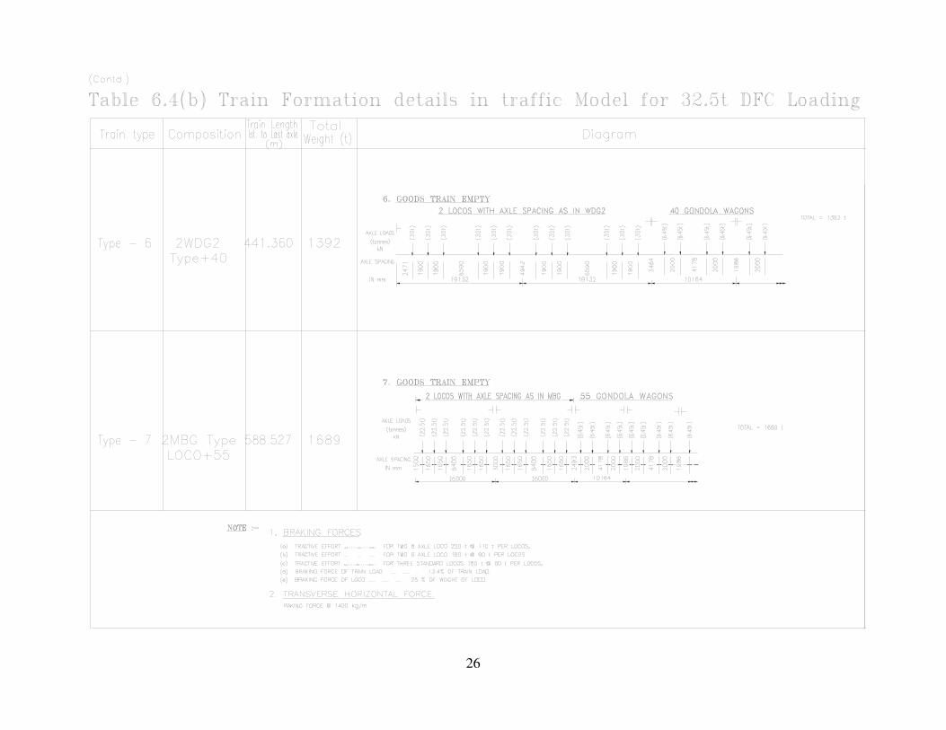
26

27
7. Determination of stresses
7.1. General
7.1.1 The stresses due to the moving train loads shall be determined on the basis of static linear elastic analysis carried out in accordance with accepted principles and practices, unless otherwise stated or implied, taking into account all axial, bending and shear stresses occurring under the prescribed fatigue loading. No redistribution of loads or stresses is permitted from any consideration whatsoever.
7.1.2 Where applicable the effect of the following should be incorporated in the stress calculations :-
(a) Shear lag, restrained torsion and distortion, transverse stresses and flange
curvature
(b) Effective width of steel plates
(c) Load application away from joints, member eccentricities at joints and rigidity of
joints in triangulated skeletal structures.
The effects of the following, however, need not be included in the stress calculations
(a) Residual stresses
(b) Eccentricities arising in a standard detail
(c) Stress concentration, except when specifically stated as a requirement for a
detail or joint.
7.1.3 The nominal stresses should be calculated at the location of potential fatigue initiation. Stress concentration at details, other than those covered in Tables 9.1 to 9.6 shall be accounted for by using an appropriate stress concentration factor.
7.1.4 The stresses to be determined for purposes of assessment of fatigue shall consist of the stresses as defined in 7.2 and 7.3 for stresses in the parent material and stresses in welds respectively.
7.2. Stresses for details in the parent material
Depending upon the fatigue assessment to be carried out, either the nominal stresses or
geometric stresses shall be evaluated.
- Nominal direct stresses σ
- Nominal shear stresses τ

28
The nominal normal or direct stress when a member is under uni-axial and bending stresses,
figure-1, is as calculated according to basic strength of materials theory
A
NN =σ and
I
yMM
*=σ
Where N and M are the axial force and bending moment at the section
A and I are the cross sectional area and moment of inertia, and
y is the distance from the neutral axis to the extreme fiber.
When geometric stress concentration occurs, figure-2, the stress should be determined as
follows
σG = kf * σN,net
where σG is the effective stress
kf is the stress concentration factor
and σN,net is the stress calculated on the net area
It shall be ensured that the effects of the stresses considered individually and in conjunction
satisfy the fatigue requirements for the structural joint or detail, as applicable.

29
Figure- 1 Nomination stress and geometric stress concentration
Figure- 2 stresses in fillet welds
7.3. Stresses in the welds
In load carrying partial penetration or fillet welded joints, the forces transmitted by a unit
length of weld shall be resolved into components transverse and parallel to the longitudinal
axis of the weld.

30
The fatigue stresses in the weld will consist of the following;
- Normal stresses σw transverse to the axis of the weld
- Shear stresses τw longitudinal to the axis of the weld
The stresses σw and τw may be obtained by dividing the relevant component of the force
transmitted per unit length of the weld, by the throat size ‘a’.
Alternatively, σw and τw may be obtained by the following, figure 2.
-
22
ffw ⊥⊥ += τσσ
- τw =τ||f
It will be necessary to ensure that the effects of the stresses considered individually and in
conjunction satisfy the fatigue requirements for the structural joint or detail, as applicable.
8. Determination of stress ranges and cycles
8.1. General Typical load events produce a stress history, with respect to the position of the leading train
axle, depending on the location of the structural detail or joint being assessed for fatigue.
This variation of stress in the stress history can be highly irregular except in those cases
where a simplified analysis is conducted in accordance with clause 12.5.
8.1.1 The stress history as stated above cannot be used directly to assess the damage using Palmgren-Miner cumulative damage rule which requires the number of occurrences
(cycles) ni of stress range ∆σi.
8.1.2 The purpose of cycle counting is to reduce a complex stress history to a sequence of stress ranges and the corresponding number of cycles of occurrence in the stress history.
8.2. Methods of cycle counting
There are two established methods of cycle counting namely the “Rainflow method” and the
“Reservoir method”, both yielding identical results provided that rainflow counting begins with
the highest peak in the loading event. Generally, rainflow counting is more suited to
computer analyses of long stress histories, whereas the reservoir method is most convenient
for graphical analyses of short histories.

31
8.2.1 Determination of stress ranges and cycles by the reservoir method
This method of cycle counting is most suited to stress histories consisting of a few peaks and
troughs as produced by simplified analysis using recommended equivalent loads. The method
consists of imagining the stress history as the section of a reservoir which is drained
successively from each of the lowest points till the reservoir is empty. Each draining operation
is considered to be equivalent to one cycle of a stress range equal in magnitude to the
maximum height of water drained in that particular operation (see Appendix G-A).
8.2.2 Determination of stress ranges and cycles by the rainflow method
The rainflow method as the name suggests counts half cycles based on the visualization of the
complex stress history as a sequence of pagoda roofs over which rain tickles down. In order to
achieve the above the stress history is rotated by 90o (see Appendix G-A).
The rules for counting half cycles are as follows:-
- A drop begins to flow left from the upper side of a peak or right from the lower side of a trough onto subsequent roofs unless the surface receiving the drop is formed by a peak which is more positive than the origin of the drop for a left flow, or, a trough that is more negative for a right flow.
- The path of a drop cannot cross the path of a drop which has fallen from a higher roof.
- The horizontal displacement of the drop from its origin to its final position measured in appropriate stress units represents a half cycle of the associated stress range.
8.3. Modification of stress ranges
8.3.1 General
The fatigue assessment should be carried out using
(a) Nominal stress ranges for details shown in tables 9.1 to 9.5
(b) Modified nominal stress ranges where abrupt changes of section occur close to
the initiation of potential crack locations (for details not covered in tables 9.1 to
9.5)
(c) Geometric stress ranges where high stress gradients occur close to a weld in
toe joints covered in table 9.6

32
The design values of stress range to be used for the fatigue assessment should be the stress
range γFf* ∆σE,2 corresponding to NC = 2 x 10⁶ cycles.
8.3.2 Design value of nominal stress range
The design value of nominal stress ranges γFf *∆σE,2 and γFf *∆τE,2 should be determined
as follows:
γFf *∆σE,2 = λ1 * λ2 *λ3 *λ4 * …. λn * ∆σ(γFf *Qk)
γFf *∆τE,2 = λ1 * λ2 *λ3 *λ4 * …. λn * ∆τ(γFf *Qk)
Where, ∆σ(γFf *Qk) and/or ∆τ(γFf *Qk) is the stress range caused by the specified fatigue
loads and λi are the damage equivalence factors as applicable and specified.
8.3.3 Design value of modified nominal stress range
The design value of modified nominal stress ranges γFf *∆σE,2 and γFf *∆τE,2 should be
determined as follows:
γFf *∆σE,2 = kf * λ1 * λ2 *λ3 *λ4 * …. λn * ∆σ(γFf *Qk)
γFf ∆τE,2 = kf * λ1 * λ2 *λ3 *λ4 * …. λn * ∆τ(γFf *Qk)
where kf is the stress concentration factor to take into account the local stress
magnification in relation to detail geometry not included in the reference S - N curves.
The kf values may be adopted from standard references or from finite element
calculations.
8.3.4 Design value of stress range for geometrical (hot spot) stress
The design value of geometrical (hot spot) stress range γFf *∆σE,2 should be determined
as follows :
γFf *∆σE,2 = kf (γFf *∆σ*E,2)
where kf is the stress concentration factor.

33
9. Classification of details
9.1. The structural connections and details, non-welded and welded, are divided into several classes, each corresponding to a specific S-N curve depending upon
- The geometrical arrangement of the detail - The direction of the fluctuating stress relative to the detail - The location of potential crack and direction of propagation - The method of fabrication and inspection of the detail
In some welded joints, there are several locations at which fatigue cracks may develop, e. g. at
the weld toe in each of the parts joined, at the weld ends, and/or in the weld itself. Each such
location should be classified separately and assessed independently for fatigue performance.
9.2. The classification of structural connections and details has been done as follows :-
Table 9.1 Non-welded details Table 9.2 Welded built-up sections
Table 9.3 Transverse butt welds Table 9.4 Welded attachments and stiffeners
Table 9.5 Load carrying welded joint Table 9.6 Fatigue resistance against geometric stress
NOTE: Table 9.6 does not cover effects of misalignment. They have to be considered explicitly in
determination of stress. Further, it does not cover fatigue initiation from the root followed by
propagation through the throat.

34
Table 9.1 Non-welded details
Detail
category
Constructional Detail Description Requirements
160
NOTE: The fatigue strength curve associated with category 160 is the highest. No detail can reach a better fatigue strength at any number of cycles.
21
Rolled and extruded products: 1) Plates and flats 2) Rolled sections
Details 1) to 2) Sharp edges, surface and
rolling flaws to be improved
by grinding until removed and
smooth transition achieved.
125
3
3) Sheared or gas cut plates: Machine gas cut or sheared material subsequently dressed to remove all edge discontinuities.
3) All visible signs of edge discontinuities to be removed. The cut areas are to be machined or ground and all burrs to be removed. Any machinery scratches for example from grinding operations can only be parallel to the stresses.
Detail 3 - Re-entrant corners to be
improved by grinding (slope < ¼) or evaluated using the appropriate stress concentration factors.
- No repair by weld refill.
For detail 1-3 made of weathering steel use the next lower category
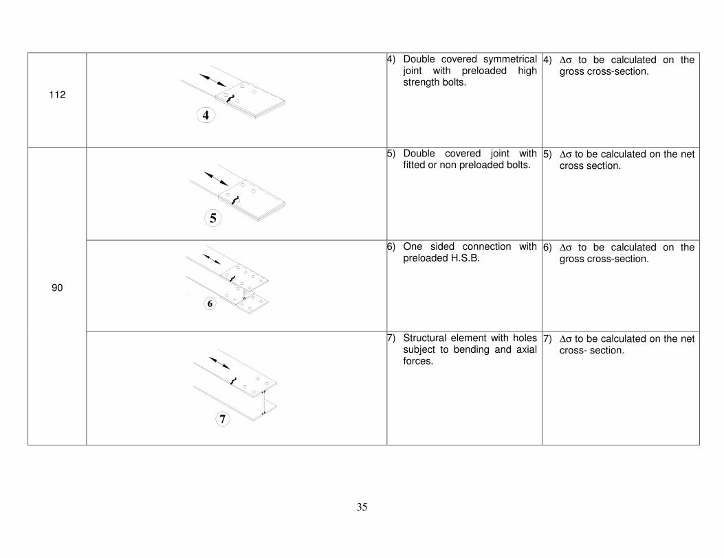
35
112
4
4) Double covered symmetricaljoint with preloaded highstrength bolts.
4) ∆σ to be calculated on thegross cross-section.
90
5
5) Double covered joint withfitted or non preloaded bolts.
5) ∆σ to be calculated on the netcross section.
6
6) One sided connection withpreloaded H.S.B.
6) ∆σ to be calculated on thegross cross-section.
7
7) Structural element with holessubject to bending and axialforces.
7) ∆σ to be calculated on the netcross- section.
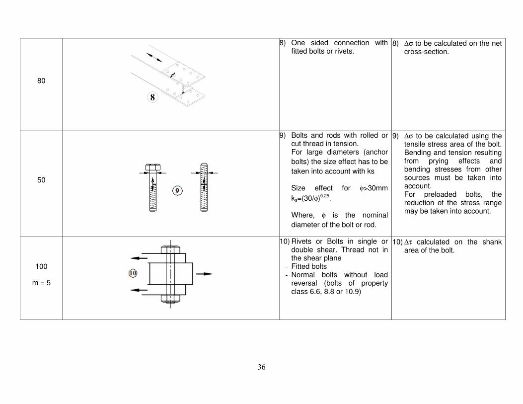
36
80
8
8) One sided connection with fitted bolts or rivets.
8) ∆σ to be calculated on the net cross-section.
50
9) Bolts and rods with rolled or cut thread in tension. For large diameters (anchor
bolts) the size effect has to be
taken into account with ks
Size effect for φ>30mm
ks=(30/φ)0.25.
Where, φ is the nominal
diameter of the bolt or rod.
9) ∆σ to be calculated using the tensile stress area of the bolt. Bending and tension resulting from prying effects and bending stresses from other sources must be taken into account. For preloaded bolts, the reduction of the stress range may be taken into account.
100
m = 5
10) Rivets or Bolts in single or double shear. Thread not in the shear plane
- Fitted bolts - Normal bolts without load
reversal (bolts of property class 6.6, 8.8 or 10.9)
10) ∆τ calculated on the shank area of the bolt.

37
Table 9.2 Welded built-up sections
Detail
category
Constructional Detail Description Requirements
125
1 2
Continuous longitudinal welds: 1) Automatic butt welds carried
out from both sides. 2) Automatic fillet welds Cover
plate ends to be checked using detail 5) or 6) Table 9.5.
Details 1) to 2) No stop/start position is
permitted except when the
repair is performed and
inspection is carried out to
verify the proper execution of
the repair.
112
4
3
3) Automatic fillet or butt weld carried out from both sides but containing stop/start positions.
4) Automatic butt welds made from one side only, with a continuous backing bar, but without stop/start positions.
4) When this detail contains stop/start positions category 100 to be used.
100
65
5) Manual fillet or butt weld. 6) Manual or automatic butt weld
carried out from one side only, particularly for box girders.
6) A very good fit between the flange and web plates is essential. The web edge to be prepared such that the root face is adequate for the achievement of regular root penetration without break-out.

38
100
7
7) Repaired automatic or manual fillet or butt welds for categories 1-6 above.
7) Improvement by grinding performed by specialist to remove all visible signs and adequate verification can restore the original category.
80
8) Intermittent longitudinal fillet welds.
8) ∆σ based on normal stress in flange.
71
9
9) Longitudinal butt weld, fillet weld or intermittent weld with cope holes, cope holes not higher than 60mm.
9) ∆σ based on normal stress in flange.
125
10
10) Longitudinal butt welds, both sides ground flush parallel to load direction, 100% NDT.
112 10) No grinding and no
start/stop.
90 10) With start/stop positions.
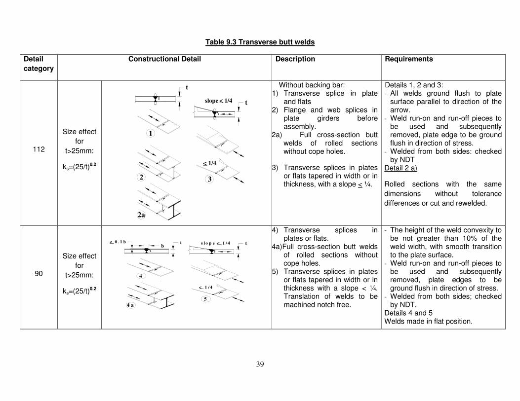
39
Table 9.3 Transverse butt welds
Detail
category
Constructional Detail Description Requirements
112
Size effect
for
t>25mm:
ks=(25/t)0.2
2a
2
< 1/4
3
<slope 1/4 t
1
t Without backing bar: 1) Transverse splice in plate
and flats2) Flange and web splices in
plate girders beforeassembly.
2a) Full cross-section butt welds of rolled sections without cope holes.
3) Transverse splices in platesor flats tapered in width or inthickness, with a slope < ¼.
Details 1, 2 and 3: - All welds ground flush to plate
surface parallel to direction of the arrow.
- Weld run-on and run-off pieces to be used and subsequently removed, plate edge to be ground flush in direction of stress.
- Welded from both sides: checked by NDT
Detail 2 a)
Rolled sections with the same
dimensions without tolerance
differences or cut and rewelded.
90
Size effect
for
t>25mm:
ks=(25/t)0.2
< 0 . 1 bb
4 a
4
t < t
< 1 / 4
s l o p e 1 / 4
5
4) Transverse splices in plates or flats.
4a)Full cross-section butt welds of rolled sections without cope holes.
5) Transverse splices in platesor flats tapered in width or inthickness with a slope < ¼.Translation of welds to bemachined notch free.
- The height of the weld convexity to be not greater than 10% of the weld width, with smooth transition to the plate surface.
- Weld run-on and run-off pieces to be used and subsequently removed, plate edges to be ground flush in direction of stress.
- Welded from both sides; checked by NDT.
Details 4 and 5 Welds made in flat position.

40
90
Size effect
for
t>25mm:
ks=(25/t)0.2 4b
4b)Full cross-section butt welds of rolled sections with cope holes.
- All weld ground flush to plate surface parallel to direction of the arrow.
- Weld run-on and run-off pieces to be used and subsequently removed, plate edges to be ground flush in direction of stress.
- Welded from both sides; checked by NDT.
- Rolled sections with the same dimensions without tolerance differences.
80
Size effect
for
t>25mm:
ks=(25/t)0.2
b< 0.2b t
7
6
6a
6) Transverse splices inwelded plate girders withoutcope hole.
6a) Full cross-section butt welds of rolled sections with cope holes.
7) Transverse splice in plates,flats, rolled sections or plategirders.
- The height of the weld convexity to be not greater than 20% of the weld width, with smooth transition to the plate surface.
- Weld not ground flush. - Weld run-on and run-off pieces to
be used and subsequently removed, plate edge to be ground flush in direction of stress.
- Welded from both sides; checked by NDT.
Detail 6a: The height of the weld convexity to be not greater than 10% of the weld width, with smooth transition to the plate surface.

41
63
8
8) Full cross-section butt welds of rolled sections without cope hole.
- Weld run-on and run-off pieces to be used and subsequently removed, plate edges to be ground flush in direction of stress.
- Welded from both sides.
36
9
t
9) Butt welds made from one side only
12) Without backing strip.
71
Size effect
for
t>25mm:
ks=(25/t)0.2
9) Butt welds made from one side only when full penetration checked by appropriate NDT.
71
Size effect
for
t>25mm:
ks=(25/t)0.2
With backing strip: 10) Transverse splice. 11) Transverse butt weld
tapered in width or thickness with a slope < ¼. Also valid for curved plates.
Details 10) and 11): Fillet welds attaching the backing strip to terminate > 10mm from the edges of the stressed plate.

42
50
Size effect
for
t>25mm:
ks=(25/t)0.2
1/4<
12) Transverse butt weld on a permanent backing strip tapered in width or thickness with a slope < ¼. Also valid for curved plates.
12) Where backing strip fillet welds end < 10 mm from the plate edge, or if a good fit cannot be guaranteed.
As
detail
1 in
Table
9.5
13) Transverse butt weld at crossing flanges.
Details 13) and 14) The fatigue strength in the perpendicular direction has to be checked with Table 9.4 detail 4 or detail 5.
As
detail
4 in
Table
9.4
14) With transition radius according to Table 9.4, detail 4.

43
Table 9.4 Welded attachments and stiffeners
Detail
categ
ory
Constructional Detail Description Requirements
80 L<50mm
LL
1
Longitudinal attachments:
1) The detail category varies according to the length of the attachment L.
The thickness of the attachment
must be less than its height. If
not see Table 9.5, details 5 or 6. 71 50<L<8
0mm
63 80<L<1
00mm
56
L>100m
m
71
L>100m
m
α<45o
L
2
L
2) Longitudinal attachments to plate or tube.
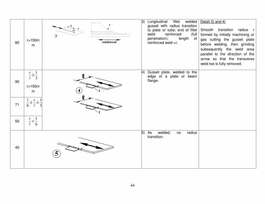
44
80 r>150m
m
Lr
r
reinforced
3
3) Longitudinal fillet weldedgusset with radius transitionto plate or tube; end of filletweld reinforced (fullpenetration); length ofreinforced weld >r.
Detail 3) and 4)
Smooth transition radius r
formed by initially machining or
gas cutting the gusset plate
before welding, then grinding
subsequently the weld area
parallel to the direction of the
arrow so that the transverse
weld toe is fully removed.
90 3
1≥
l
r
r>150m
m
4) Gusset plate, welded to theedge of a plate or beamflange.
71 3
1
6
1≤≤
l
r
50 6
1<
l
r
40
5) As welded, no radius transition.

45
80 ℓ<50mm
Transverse attachments
6) Welded to plate. 7) Vertical stiffeners welded to a
beam or plate girder. 8) Diaphragm of box girders
welded to the flange or the web. Not possible for hollow sections. The values are also valid for
ring stiffeners.
Details 6) and 7):
Ends of welds to be carefully
ground to remove any undercut
that may be present.
7) ∆σ to be calculated using principal stresses if the stiffener terminates in the web.
71 50<ℓ<80
mm
80
9
9) The effect of welded shear studs on base material.
∆τ to be calculated on the
nominal cross section of the
stud.
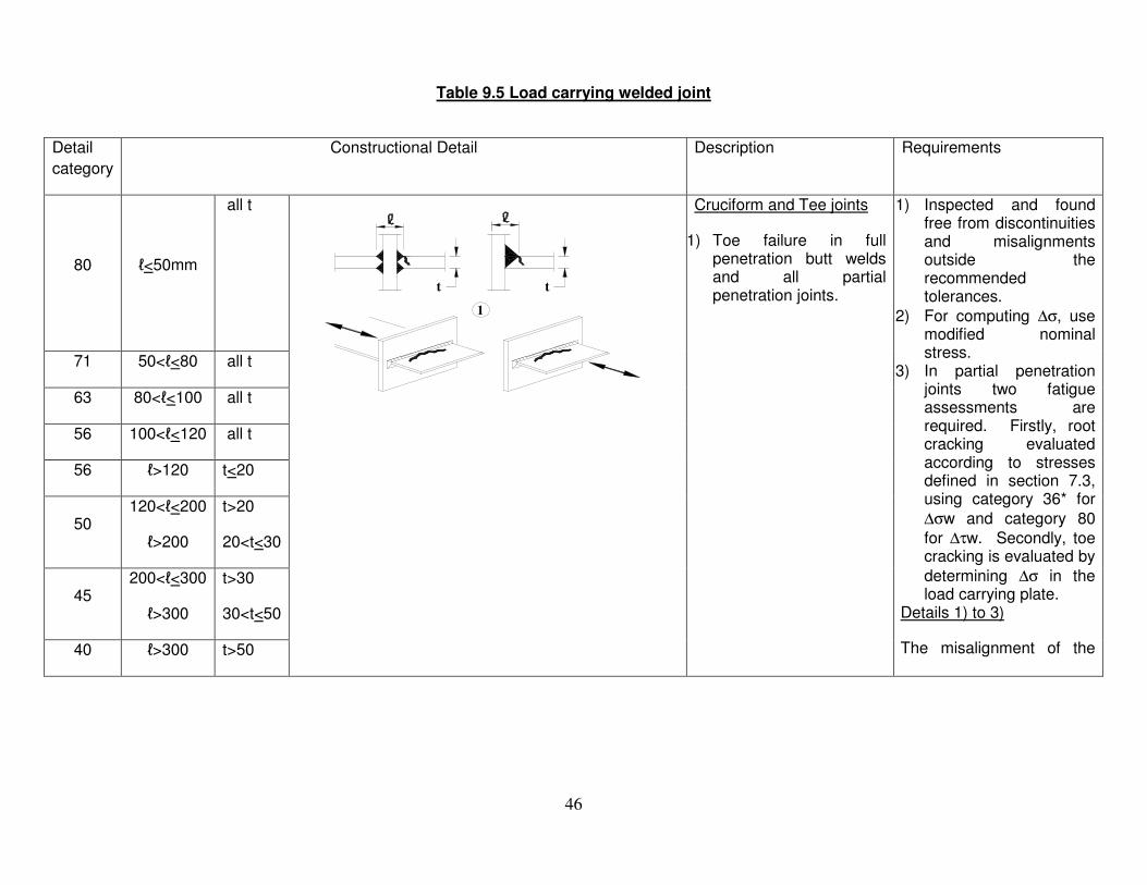
46
Table 9.5 Load carrying welded joint
Detail
category
Constructional Detail Description Requirements
80 ℓ<50mm
all t
t t
1
Cruciform and Tee joints
1) Toe failure in full penetration butt welds and all partial penetration joints.
1) Inspected and found free from discontinuities and misalignments outside the recommended tolerances.
2) For computing ∆σ, use modified nominal stress.
3) In partial penetration joints two fatigue assessments are required. Firstly, root cracking evaluated according to stresses defined in section 7.3, using category 36* for
∆σw and category 80
for ∆τw. Secondly, toe cracking is evaluated by
determining ∆σ in the load carrying plate.
Details 1) to 3)
The misalignment of the
71 50<ℓ<80 all t
63 80<ℓ<100 all t
56 100<ℓ<120 all t
56 ℓ>120 t<20
50 120<ℓ<200
ℓ>200
t>20
20<t<30
45 200<ℓ<300
ℓ>300
t>30
30<t<50
40 ℓ>300 t>50

47
As detail
1 in
Table
9.5 t
2
flexible panel
2) Toe failure from edge of attachment to plate, with stress peaks at weld end due to local plate deformations.
load-carrying plates should
not exceed 15% of the
thickness of the
intermediate plate.
36*
3
3) Root failure in partial penetration Tee-built joint or fillet welded joint and effective full penetration in Tee-butt joint.
As detail
1 in
Table
9.5 t
>10 mm
>10 mm stressed areaof main plate
slope 1/24
Overlapped welded joints
4) Fillet welded lap joint.
4) ∆σ in the main plate to be calculated on the basis of area shown in the sketch.
45*
5
>10 mm
Overlapped
5) Fillet welded lap joint.
5) ∆σ to be calculated in the overlapping plates.
Details 4) and 5)
- Welded terminations more than 10 mm from plate edge.
- Shear cracking in the weld should be checked using detail 8).

48
tc<t tc>t Cover plates in beams and plate girders
6) End zones of single ormultiple welded coverplates, with or withoutfrontal weld.
6) If the cover plate iswider than the flange, afrontal weld is needed.This weld should becarefully ground toremove undercut.The minimum length of
the cover plate is
300mm. For shorter
attachments see detail
1).
56* t<20 -
50 20<t<30 t<20
45 30<t<50 20<t<30
40 t>50 30<t<50
36 - t>50
56
7
reinforced front weld
t
t
5tc
7) Cover plates in beamsand plate girders.5 tc is the minimum
length of the
reinforcement weld.
7) Front weld ground flush.In addition, if tc>20mm,front of plate at the endground with a slope <¼.
80
m=5 9
>10 mm
8
8) Continuous fillet weldstransmitting a shearflow, such as web toflange welds in plategirders.
9) Fillet welded lap joint.
8) ∆τ to be calculated fromthe weld throat area.
9) ∆τ to be calculated fromthe weld throat areaconsidering the totallength of the weld.Weld terminations morethan 10mm from theplate edge.

49
Table 9.6 : Fatigue resistance against geometric stress
Detail category
Constructional details
Description Requirements
112
1
1) Full penetration butt joint.
1)
− All welds ground flush to plate surface parallel to direction of the arrow.
− Weld run-on and run-off pieces to be used and subsequently removed, plate edges to be ground flush in direction of stress.
− Welded from both sides, checked by NDT.
− For misalignment see note 1 below.
100
2
2) Full penetration butt joint.
2)
− Weld not ground flush
− Weld run-on and run-off pieces to be used and subsequently removed, plate edges to be ground flush in direction of stress.
− Welded from both sides.
− For misalignment see note 1 below
100 3
3) Cruciform joint with full penetration K-butt welds.
3)
− Weld toe angle < 60o
− For misalignment see note 1 below.
100 4
4) Non load-carrying fillet welds.
4) Weld toe angle < 60o (see note 2 below)
100 5
5) Bracket ends, ends of longitudinal stiffeners.
5) Weld toe angle < 60o (see note 2 below)

50
100 6
6) Cover plate endand similar joints.
6) Weld toe angle < 60o
(see note 2 below)
90 7
7) Cruciform jointswith load-carryingfillet welds.
7) Weld toe angle < 60o
(see notes 1 and 2 below)
NOTE 1. Table 9.6 does not cover effects of misalignment. They have to be considered explicitly in determination of stress.
NOTE 2. Table 9.6 does not cover fatigue initiation from the root followed by propagation through the throat.
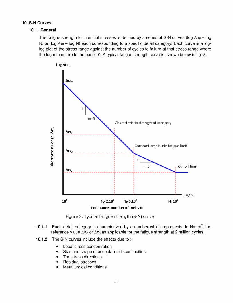
51
10. S-N Curves
10.1. General
The fatigue strength for nominal stresses is defined by a series of S-N curves (log ∆σR – log
N, or, log ∆τR – log N) each corresponding to a specific detail category. Each curve is a log-
log plot of the stress range against the number of cycles to failure at that stress range where
the logarithms are to the base 10. A typical fatigue strength curve is shown below in fig.-3.
10.1.1 Each detail category is characterized by a number which represents, in N/mm2, the
reference value ∆σC or ∆τC as applicable for the fatigue strength at 2 million cycles.
10.1.2 The S-N curves include the effects due to :-
• Local stress concentration
• Size and shape of acceptable discontinuities
• The stress directions
• Residual stresses
• Metallurgical conditions

52
10.2. Specification of S-N curves
The fatigue strength curves for constant amplitude nominal stresses are as shown in figures
4 and 5 and are defined as :-
NR *(∆σR)m = 2 * 106 * (∆σC)m with m=3 for N ≤ 5*106
NR *(∆τR)m = 2 * 106 * (∆τC)m with m=5 for N ≤ 108
where CCD σσσ ∆=∆
=∆ 7368.0*5
2 31
is the constant amplitude fatigue limit
and CCL τττ ∆=∆
=∆ 4573.0*100
2 51
is the cut off limit at 100 million cycles
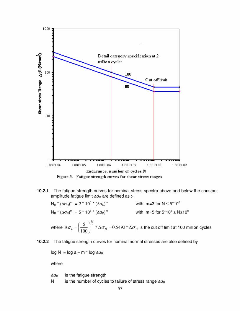
53
10.2.1 The fatigue strength curves for nominal stress spectra above and below the constant
amplitude fatigue limit ∆σD are defined as :-
NR * (∆σR)m = 2 * 106 * (∆σC)m with m=3 for N ≤ 5*106
NR * (∆σR)m = 5 * 106 * (∆σD)m with m=5 for 5*106 ≤ N≤108
where DDL σσσ ∆=∆
=∆ *5493.0*100
5 51
is the cut off limit at 100 million cycles
10.2.2 The fatigue strength curves for nominal normal stresses are also defined by
log N = log a – m * log ∆σR
where
∆σR is the fatigue strength
N is the number of cycles to failure of stress range ∆σR

54
m is the constant slope of the fatigue strength curves
log a is a constant which depends on the specific segment of the fatigue curve
The numerical values for the fatigue strength curves for normal and shear stress
ranges are as given in Tables 10.1 and 10.2 respectively.
Table 10.1 Numerical values for fatigue strength curves for normal stress ranges
Detail Category
∆∆∆∆σσσσC
(N/mm2)
log a for N ≤≤≤≤ 108 Stress Range at Constant amplitude
Fatigue limit (N = 5*106)
∆∆∆∆σσσσD
(N/mm2)
Stress Range at
Cut off limit
(N = 108)
∆∆∆∆σσσσL
(N/mm2)
Limiting Stress Range
(N = 104)
∆∆∆∆σσσσSL
(N/mm2)
N ≤≤≤≤ 5 * 106
m = 3 N ≥≥≥≥ 5 * 106
m = 5
160 12.913 17.056 118 65 936
140 12.739 16.766 103 57 819
125 12.592 16.520 92 51 731
112 12.449 16.282 83 45 655
100 12.301 16.036 74 40 585
90 12.164 15.807 66 36 526
80 12.010 15.551 59 32 468
71 11.855 15.292 52 29 415
63 11.699 15.032 46 25 368
56 11.546 14.777 41 23 327
50 11.398 14.531 37 20 292
45 11.261 14.302 33 18 263
40 11.107 14.046 29 16 234
36 10.970 13.817 27 15 211
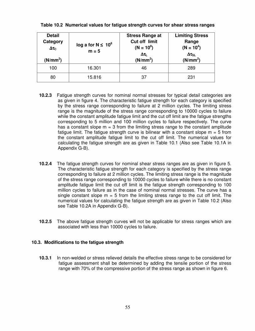
55
Table 10.2 Numerical values for fatigue strength curves for shear stress ranges
Detail
Category
∆∆∆∆ττττC
(N/mm2)
log a for N ≤≤≤≤ 108
m = 5
Stress Range at
Cut off limit
(N = 108)
∆∆∆∆ττττL
(N/mm2)
Limiting Stress
Range
(N = 104)
∆∆∆∆ττττSL
(N/mm2)
100 16.301 46 289
80 15.816 37 231
10.2.3 Fatigue strength curves for nominal normal stresses for typical detail categories are as given in figure 4. The characteristic fatigue strength for each category is specified by the stress range corresponding to failure at 2 million cycles. The limiting stress range is the magnitude of the stress range corresponding to 10000 cycles to failure while the constant amplitude fatigue limit and the cut off limit are the fatigue strengths corresponding to 5 million and 100 million cycles to failure respectively. The curve has a constant slope m = 3 from the limiting stress range to the constant amplitude fatigue limit. The fatigue strength curve is bilinear with a constant slope m = 5 from the constant amplitude fatigue limit to the cut off limit. The numerical values for calculating the fatigue strength are as given in Table 10.1 (Also see Table 10.1A in Appendix G-B).
10.2.4 The fatigue strength curves for nominal shear stress ranges are as given in figure 5. The characteristic fatigue strength for each category is specified by the stress range corresponding to failure at 2 million cycles. The limiting stress range is the magnitude of the stress range corresponding to 10000 cycles to failure while there is no constant amplitude fatigue limit the cut off limit is the fatigue strength corresponding to 100 million cycles to failure as in the case of nominal normal stresses. The curve has a single constant slope m = 5 from the limiting stress range to the cut off limit. The numerical values for calculating the fatigue strength are as given in Table 10.2 (Also see Table 10.2A in Appendix G-B).
10.2.5 The above fatigue strength curves will not be applicable for stress ranges which are associated with less than 10000 cycles to failure.
10.3. Modifications to the fatigue strength
10.3.1 In non-welded or stress relieved details the effective stress range to be considered for fatigue assessment shall be determined by adding the tensile portion of the stress range with 70% of the compressive portion of the stress range as shown in figure 6.

56
10.3.2 To account for the influence on the fatigue strength of the thickness of the parent metal in which the potential cracks may initiate and propagate.
10.3.2.1 The reduction in the fatigue strength will be applicable only to those structural details with welds transverse to the direction of the normal stresses.
10.3.2.2 The variation of fatigue strength with thickness, of the parent metal, greater than 25 mm shall be accounted for by reducing the fatigue strength as :-
20.0
, )/25(* tRtR σσ ∆=∆
10.3.2.3 Where the material thickness of the structural detail is less than 25 mm the fatigue strength shall be taken as that for a thickness of 25 mm
RtR σσ ∆=∆ ,
10.3.2.4 Where the detail category in the classification tables indicates a specific variation in the fatigue strength with thickness then 10.3.2.2 will not be applicable.
10.3.3 Modified fatigue strength is applicable to structural details duly marked with an asterisk in the detail classification table 9.5. Such details have been allocated a category lower than the stress range corresponding to 2 million cycles. The classification of such details may be upgraded by one category provided that fatigue strength curves are adopted such that the constant amplitude fatigue limit is at 10 million cycles for a slope of m = 3 as shown in figure 7.
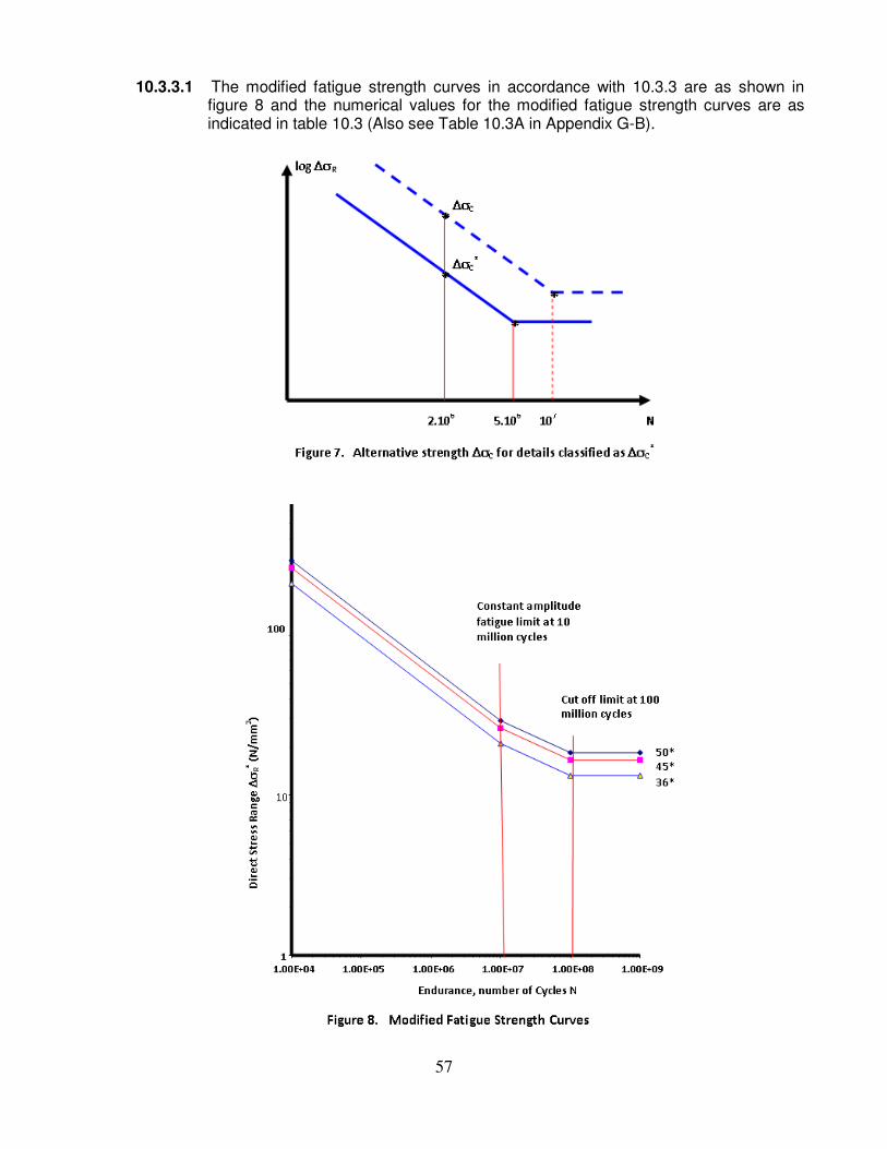
57
10.3.3.1 The modified fatigue strength curves in accordance with 10.3.3 are as shown in figure 8 and the numerical values for the modified fatigue strength curves are as indicated in table 10.3 (Also see Table 10.3A in Appendix G-B).

58
Table 10.3 Numerical values for modified fatigue strength curves for normal
stress ranges
Detail
Category
∆∆∆∆σσσσC
(Nominal)
log a for N ≤≤≤≤ 108 Stress Range at
Constant amplitude
Fatigue limit
(N = 107)
∆∆∆∆σσσσD
(N/mm2)
Stress Range
at
Cut off limit
(N = 108)
∆∆∆∆σσσσL
(N/mm2)
Limiting Stress
Range
(N = 104)
∆∆∆∆σσσσSL
(N/mm2)
N ≤≤≤≤ 107
m = 3
N ≥≥≥≥ 107
m = 5
50*(56) 11.546 14.576 33 21 327
45*(50) 11.398 14.330 29 18 292
36*(40) 11.107 13.845 23 15 234
NOTE: Values in parentheses indicate the next higher category for which the constants are evaluated
as per 10.3.3.
11. Partial safety factors
11.1. General
The values of the partial safety factors to be used shall be as specified herein unless
otherwise recommended by the appropriate competent authority, taking into due
consideration:
(a) the ease of access for inspection or repair and likely frequency of inspection
and maintenance,
(b) the consequences of failure.
11.2. Partial safety factor for fatigue loading γγγγFf
11.2.1 To take account of uncertainties in the fatigue response analysis, the design stress ranges for the fatigue assessment procedure shall incorporate a partial safety factor
γγγγFf.
The partial safety factor γγγγFf covers the uncertainties in estimating:
(a) the applied load levels,
(b) the conversion of these loads into stresses and stress ranges,
(c) the equivalent constant amplitude stress range from the design stress
range spectrum,
(d) the design life of the structure, and the evolution of the fatigue loading
within the required design life of the structure.

59
11.3. Partial safety factor for fatigue strength γγγγMf
11.3.1 In the fatigue assessment procedure, in order to take account of uncertainties in the fatigue resistance, the design value of the fatigue strength shall be obtained by
dividing by a partial safety factor γγγγMf .
The factor γγγγMf covers the uncertainties due to the effects of:
(a) the size of the detail,
(b) the dimensions, shape and proximity of the discontinuities,
(c) local stress concentrations due to welding uncertainties.
(d) variable welding processes and metallurgical effects.
11.4 Values of partial safety factors – Unless otherwise stated in subsequent parts of this document or by any other document which supersedes the provisions contained
herein, the values of the partial safety factor for fatigue loading (γγγγFf) and fatigue
strength (γγγγMf) shall be taken as follows;
γγγγFf = 1.00
γγγγMf = 1.15
12. Fatigue assessment procedures
12.1. Limitations and exceptions
12.1.1 Limitations
- For fatigue assessment, all nominal stresses, direct or shear, shall be within the elastic limits of the material. The range of the design values of such stresses
shall not exceed 1.5 fy for normal stresses or 1.5 fy/√3 for shear stresses.
- The fatigue strengths specified in this document are applicable to structures where suitable corrosion protection measures have been undertaken and corrosion is not allowed to take place.
- The fatigue assessment procedures herein are applicable only to structures subjected to temperatures not exceeding 150 °C.
60
- The constant amplitude stress range or a component of the variable amplitude stress ranges, under the prescribed fatigue loading, for a structural connection or detail is such that either the nominal stress range exceeds the limiting stress or the endurance is equal to or less than 10,000 cycles.
12.1.2 Exceptions
No fatigue assessment is required when any of the following conditions is satisfied;
12.1.2.1 The largest nominal stress range ∆σ satisfies
MfFf γσγ 26* ≤∆ N/mm2
12.1.2.2 The total number of stress cycles N satisfies 3
2,
6
*
36*102
∆≤
EFf
MfxN
σγ
γ
where ∆σE,2 is the equivalent constant amplitude stress range in N/mm2 .
12.1.2.3 For a detail for which a constant amplitude fatigue limit ∆σD is specified, the
largest stress range (nominal or geometric as appropriate) ∆σ satisfies
MfDFf γσσγ /* ∆≤∆
12.2. General
12.2.1 The assessment for fatigue shall be carried out either
- in terms of cumulative damage by comparing the applied damage to the limiting damage, or
- in terms of the equivalent stress range by comparing it with the fatigue strength for a given number of stress cycles.
12.2.2 For a particular class of constructional detail, the stresses to be considered may be normal stresses or shear stresses or both.
12.2.3 When a constructional detail is defined in the detail classification tables (Table 9.1 to Table 9.5) the nominal stress range shall be used, see 12.3.

61
12.2.4 The effects of geometric discontinuities which are not part of the constructional detail itself, such as holes, cut-outs or re-entrant corners shall be taken into account separately, either by a special analysis or by the use of appropriate stress concentration factors, to determine the modified nominal stress range.
12.2.5 When a constructional detail differs from a detail defined in the detail classification tables by the presence of a geometric discontinuity in the detail itself, the geometric stress range shall be used, see 12.4.
12.2.6 For constructional details not included in the detail classification tables, the geometric stress range shall be used, see 12.4.
12.3. Fatigue assessment based on nominal stress ranges
12.3.1 Constant amplitude loading
For constant amplitude loading the fatigue assessment criterion is:
MfRFf γσσγ /* ∆≤∆
where ∆σ is the nominal stress range
and ∆σR is the fatigue strength for the relevant detail category for the total
number of cycles N during the required design life.
12.3.2 Variable amplitude loading
12.3.2.1 For variable amplitude loading defined by a design spectrum, the fatigue assessment shall be based on Palmgren-Miner rule of cumulative damage.
12.3.2.2 If the maximum stress range due to the variable amplitude loading is higher than the constant amplitude fatigue limit, then one of the following types of fatigue assessment shall be made;
- Cumulative damage - Equivalent constant amplitude
12.3.2.3 A cumulative damage assessment may be made using
Dd ≤ 1 where ∑=i
i
dN
nD

62
where ni and Ni are the number of cycles of stress range ∆σi during the required
design life, and the number of cycles of stress range γFf . γMf . ∆σi to cause failure for the
relevant detail category.
12.3.2.4 Cumulative damage calculations shall be based on one of the following:
(a) a fatigue strength curve with a single slope constant m = 3
(b) a fatigue strength curve with double slope constants (m = 3 and m = 5),
changing at the constant amplitude fatigue limit
(c) a fatigue strength curve with double slope constants (m = 3 and m = 5),
and a cut-off limit at N = 100 million cycles, (stress ranges below the
cut-off limit may be neglected in this case)
12.3.2.5 When 12.3.2.4(c) is adopted Ni may be calculated as follows ;
(a) if γFf . ∆σi ≥ ∆σD / γMf
3
6
**10*5
∆
∆=
iFf
MfD
iNσγ
γσ
(b) if ∆σD / γMf ≥ γFf . ∆σi ≥ ∆σL / γMf
5
6
**10*5
∆
∆=
iFf
MfD
iNσγ
γσ
(c) if ∆σL / γMf ≥ γFf * ∆σi then Ni may be taken as infinite
12.3.2.6 An equivalent constant amplitude fatigue assessment may be made by checking the criterion:
γFf * ∆σE ≤ ∆σR / γMf
Where,
∆σE is the equivalent constant amplitude stress range which, for the given
number of cycles leads to the same cumulative damage as the design
spectrum, and
∆σR is the fatigue strength for the relevant detail category for the same number
of cycles as used to determine ∆σE.
12.3.2.7 A conservative estimate of ∆σE and ∆σR may be obtained by adopting a fatigue strength curve of a single slope constant m = 3 as per 12.3.2.4(a).
63
12.3.2.8 In general, however, ∆σE may be calculated on the basis of the dual slope fatigue strength curve as per 12.3.2.4(c) as shown in figure 4.
12.3.2.9 An equivalent constant amplitude fatigue assessment may be made alternatively by the following criteria;
γFf * ∆σE,2 ≤ ∆σC / γMf
Where,
∆σE,2 is the equivalent constant amplitude stress range for 2 million cycles, and
∆σC is the reference value of the fatigue strength for the relevant detail (also at
2 million cycles).
12.3.3 Shear stress ranges
12.3.3.1 Nominal shear stress ranges , ∆τ shall be treated in the same manner as the nominal direct or normal stress ranges but with a single slope constant of m = 5.
12.3.3.2 Ni may be calculated as follows :
(a) if γFf * ∆τi ≥ ∆τL / γMf
5
6
**10*2
∆
∆=
iFf
MfD
iNτγ
γτ
(b) if γFf * ∆τi ≤ ∆τL / γMf then Ni may be taken as infinite.
12.3.4 Combination of normal and shear stress ranges
12.3.4.1 In the case of a combination of normal and shear stresses the fatigue assessment shall consider their combined effects
12.3.4.2 If the equivalent nominal shear stress range is less than 15 % of the equivalent nominal normal stress range, the effects of the shear stress range may be neglected.
12.3.4.3 At locations other than weld throats, if the normal and shear stresses induced by the same loading event vary simultaneously, or if the plane of the maximum principal stress does not change significantly in the course of a loading event, the maximum principal stress range may be used.

64
12.3.4.4 If, at the same location, normal and shear stresses vary independently, the components of damage due to normal and shear stresses shall be determined separately in accordance with the Palmgren-Miner rule and then combined in accordance with
Dd,σ + Dd,τ ≤ 1
where Dd,σ = ∑(ni / Ni ) for normal stress ranges ∆σi
and
Dd,τ = ∑(ni / Ni ) for shear stress ranges ∆τi
12.3.4.5 The criteria specified in 12.3.4.4 for equivalent constant amplitude stress ranges assumes the form
1**
53
≤
∆
∆+
∆
∆
MfR
EFf
MfR
EFf
γτ
τγ
γσ
σγ
12.3.4.6 An equivalent constant amplitude fatigue assessment may, alternatively, be made by the following criterion
1**
5
2,
3
2, ≤
∆
∆+
∆
∆
MfC
EFf
MfC
EFf
γτ
τγ
γσ
σγ
12.3.4.7 Stress ranges in welds shall be determined as specified in Para 7.3. The components of damage for normal and shear stresses shall be assessed in accordance with the Palmgren-Miner rule and then combined in accordance with
Dd,σ + Dd,τ ≤ 1
where Dd,σ = ∑(ni / Ni ) for normal stress ranges σwf
and
Dd,τ = ∑(ni / Ni ) for shear stress ranges ∆τwf
12.4. Fatigue assessment based on geometric stress ranges
12.4.1 The geometric stress is the maximum principal stress in the parent material adjacent to the weld toe taking into account only the overall geometry of the joint, excluding local stress concentration effects due to the weld geometry and discontinuities at the weld toe.

65
12.4.2 The maximum value of the geometric stress range shall be found, investigating various locations at the weld toe around the welded joint or the stress concentration area.
12.4.3 The geometric stresses may be determined using stress concentration factors obtained from parametric formulae within their domains of validity, a finite element analysis or an experimental model.
12.4.4 A fatigue assessment based on the geometric stress range, shall be treated similarly to the assessments given in 12.3, but replacing the nominal stress range by the geometric stress range.
12.4.5 The fatigue strength to be used in assessments based on geometric stress ranges shall be determined with reference to table 9.6.
12.5. Assessment for simplified load models
12.5.1 General
The recommended equivalents for train loads shall be adopted in accordance with
existing provisions of IRS Bridge Rules, including the dynamic impact factor Φ, which is
calculated as (1.0 + CDA), where CDA is the coefficient of Dynamic Augment as
specified in IRS Bridge Rules.
12.5.2 Fatigue stress spectra
12.5.2.1 For the simplified fatigue loading the following procedure may be adopted to determine the design stress spectrum, unless specified otherwise by the competent authority.
12.5.2.2 The maximum stress σP,max and the minimum stress σP,min should be determined for a detail or structural connection by evaluating influence areas.
12.5.2.3 The reference stress range ∆σP for determining the damage due to the stress spectrum should be obtained from:
min,max, PPP σσσ −=∆

66
12.5.2.4 The damage effects of the stress range spectrum may be represented by the damage equivalent stress range related to 2 million cycles as
PE σλσ ∆Φ=∆ **2,
Where,
λ is the damage equivalence factor, and
Φ is the dynamic impact factor (1.0 + CDA),
CDA is the coefficient of Dynamic Augment as specified in IRS Bridge Rules
12.5.2.5 The fatigue stress spectra may also be obtained by the evaluation of stress histories from train formation diagrams as specified in the existing Bridge Rules.
12.5.3 Fatigue assessment
The fatigue assessment shall be carried out by ensuring the satisfaction of the
following criteria:
γFf *∆σE,2 ≤ ∆σC / γMf
and
γFf *∆τE,2 ≤ ∆τC / γMf
12.5.4 Damage equivalence factors
12.5.4.1 The damage equivalent factor for railway bridges should be determined from:
λ = λ1 * λ2 * λ3 * λ4 subject to the condition that λ ≤ λmax
Where,
λ1 is a factor that takes into account the damaging effect of traffic and depends on
the base length of the longest loop of the influence line diagram
λ2 is a factor that takes into account the annual traffic volume in million tonnes
λ3 is a factor that takes into account the design life of the bridge in years
λ4 is a factor to be taken into account when the bridge structure is loaded on more
than one track
λmax is the maximum λ value taking into account the fatigue limit

67
12.5.4.2 The value of λ1 may be obtained from tables 7.1 to 7.4 for MBG loading, HM loading, 25t loading – 2008 and 32.5t loading (DFC) respectively as a function of the loaded length (see 6.9) for the train types included in respective traffic models. The loaded length shall depend upon the influence line diagram of the structural element or detail/connection under consideration. For simplified analysis the maxima for each length category could be adopted. For routes with train types other than those considered above, the competent authority may
specify alternative values of λ1.
12.5.4.3 The loaded length for the determination of the appropriate λ1 should be taken as follows:
(a) for moments:
- For a simply supported span, the span length, L - For cross girders supporting rail bearers (or stiffeners), the sum of
the spans of the rail bearers (or stiffeners) carried by the cross girder.
(b) for shear for a simply supported span
- For the support section, the span length - For the mid-span section, 0.4 * the span under consideration
(c) for axial force in members of a triangulated truss
- Base length of loop containing the largest ordinate (+ve or –ve) in the Influence Line Diagram (ILD) of the member of the truss (see Fig. 9)
(d) In other cases
- the same as for moments
U1 2U 3U 4U 5U 6U 7U
1L 2L 3L 4L 5L 6L 7L 8L0L
27000 mm
36000 mm
Figure - 9 (a) Loaded Length for Diagonal U -L3 4
Loaded Length
Figure - 9 (b) Loaded Length for Vertical U -L3
7875 mmLoaded Length
3
0L L 2 4L 8L
Figure - 9 (c) Loaded Length for Bottom Chord L -L & L -L0 1 1 2
Note :- (+) For Tension and (-) For Compression
(+)
(-)
(+)
63000 Loaded LengthL 0 1L
(+)
L 8
68
12.5.4.4 The value of λ2 , in terms of the annual volume of traffic may be obtained from the following expression:
2036.0
2 *5193.0 aT=λ
Where Ta is the annual volume of traffic expressed in million tonnes.
12.5.4.5 Unless otherwise specified by the competent authority the value of λ3 will be taken as 1.00 for a design life of 100 years. For other values of design life the corresponding value may be calculated from the following expression where LD
is the design life in years 2048.0
3 *3899.0 DL=λ
12.5.4.6 The value of λ4, assuming 15% of the total traffic on both tracks crosses whilst on the bridge, unless specified otherwise by the competent authority, shall be obtained from
9371.0*7280.0*7926.0 2
4 +−= aaλ
where
a = ∆σ1 / ∆σ1+2
∆σ1 = Stress range at the section being checked due to train on one track.
∆σ1+2 = Stress range at the same section due to train load on two tracks.
The values of λ4 may be calculated for other proportions of crossing traffic from
( ) ( )[ ]5 55
4 )11 aann −+−+=λ
Where,
n is the proportion of traffic that crosses whilst on the bridge.
12.5.4.7 The value of λ should not exceed λmax given by
λmax = 1.4

69
Table 7.1: λλλλ1 for MBG Loading
Span (m) Train-1 Train-2 Train-3 Train-4 Train-5 Train-6 Train-7 Train-8 Train-9 Train-10 Envelope
0.50 1.20 1.22 1.24 1.53 1.30 1.22 1.28 1.42 0.97 0.96 1.53
1.00 1.19 1.22 1.23 1.51 1.28 1.21 1.27 1.42 0.96 0.95 1.51
1.50 1.18 1.21 1.23 1.50 1.24 1.20 1.25 1.41 0.96 0.95 1.50
2.00 1.17 1.20 1.22 1.48 1.21 1.19 1.24 1.40 0.95 0.95 1.48
2.50 1.16 1.20 1.21 1.45 1.19 1.18 1.23 1.39 0.95 0.94 1.45
3.00 1.15 1.19 1.21 1.42 1.17 1.17 1.22 1.38 0.94 0.94 1.42
3.50 1.14 1.18 1.20 1.39 1.14 1.16 1.20 1.38 0.94 0.93 1.39
4.00 1.13 1.17 1.19 1.36 1.11 1.15 1.19 1.37 0.94 0.93 1.37
4.50 1.12 1.17 1.19 1.33 1.08 1.13 1.18 1.36 0.93 0.92 1.36
5.00 1.11 1.16 1.18 1.30 1.07 1.12 1.17 1.35 0.93 0.91 1.35
6.00 1.09 1.14 1.17 1.24 1.04 1.09 1.14 1.33 0.92 0.90 1.33
7.00 1.07 1.12 1.15 1.17 1.01 1.07 1.12 1.31 0.86 0.88 1.31
8.00 1.04 1.10 1.13 1.07 0.98 1.05 1.10 1.30 0.77 0.86 1.30
9.00 0.97 1.06 1.11 0.99 0.95 1.03 1.08 1.29 0.74 0.84 1.29
10.00 0.95 1.00 1.06 1.04 0.98 1.06 1.09 1.29 0.81 0.86 1.29
12.50 0.93 0.97 1.01 0.93 0.92 1.01 1.05 1.23 0.77 0.83 1.23
15.00 0.92 0.96 1.00 0.83 0.87 0.98 0.97 1.19 0.75 0.81 1.19
17.50 0.90 0.93 0.97 0.75 0.84 0.88 0.90 1.16 0.73 0.80 1.16
20.00 0.92 0.98 1.03 0.70 0.85 0.86 0.90 1.13 0.68 0.80 1.13
25.00 0.85 1.00 1.02 0.62 0.80 0.80 0.83 1.08 0.63 0.65 1.08
30.00 0.80 0.98 1.00 0.55 0.78 0.78 0.78 1.05 0.61 0.61 1.05
35.00 0.76 0.82 0.84 0.52 0.77 0.73 0.76 0.84 0.62 0.63 0.84
40.00 0.73 0.78 0.79 0.50 0.73 0.73 0.78 0.84 0.63 0.65 0.84
45.00 0.67 0.68 0.69 0.49 0.72 0.72 0.74 0.80 0.65 0.65 0.80
50.00 0.65 0.65 0.66 0.49 0.71 0.72 0.74 0.78 0.64 0.66 0.78
60.00 0.61 0.62 0.62 0.49 0.69 0.70 0.74 0.76 0.63 0.65 0.76
70.00 0.60 0.60 0.60 0.46 0.68 0.72 0.75 0.77 0.61 0.65 0.77
80.00 0.59 0.59 0.59 0.46 0.70 0.69 0.73 0.75 0.61 0.63 0.75
90.00 0.57 0.58 0.58 0.47 0.70 0.66 0.73 0.74 0.60 0.61 0.74
100.00 0.56 0.57 0.57 0.46 0.66 0.65 0.73 0.73 0.60 0.59 0.73
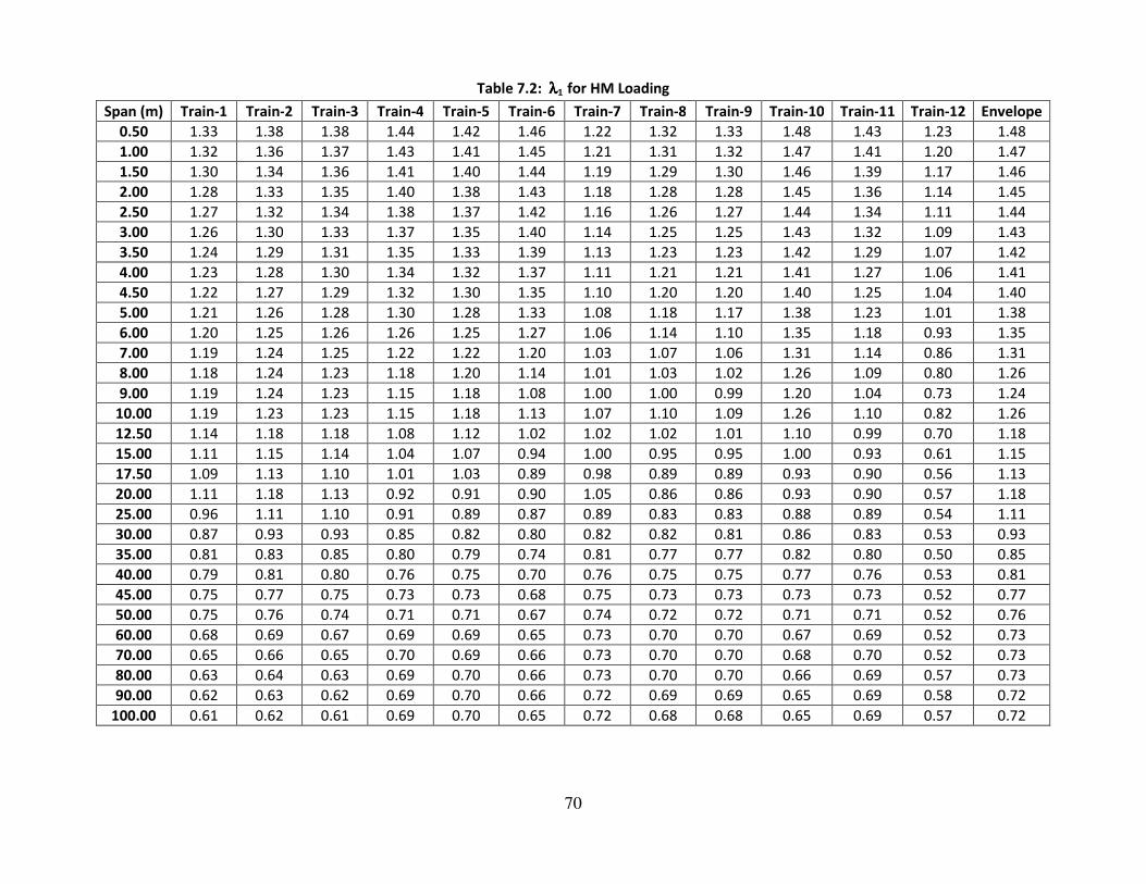
70
Table 7.2: λλλλ1 for HM Loading
Span (m) Train-1 Train-2 Train-3 Train-4 Train-5 Train-6 Train-7 Train-8 Train-9 Train-10 Train-11 Train-12 Envelope
0.50 1.33 1.38 1.38 1.44 1.42 1.46 1.22 1.32 1.33 1.48 1.43 1.23 1.48
1.00 1.32 1.36 1.37 1.43 1.41 1.45 1.21 1.31 1.32 1.47 1.41 1.20 1.47
1.50 1.30 1.34 1.36 1.41 1.40 1.44 1.19 1.29 1.30 1.46 1.39 1.17 1.46
2.00 1.28 1.33 1.35 1.40 1.38 1.43 1.18 1.28 1.28 1.45 1.36 1.14 1.45
2.50 1.27 1.32 1.34 1.38 1.37 1.42 1.16 1.26 1.27 1.44 1.34 1.11 1.44
3.00 1.26 1.30 1.33 1.37 1.35 1.40 1.14 1.25 1.25 1.43 1.32 1.09 1.43
3.50 1.24 1.29 1.31 1.35 1.33 1.39 1.13 1.23 1.23 1.42 1.29 1.07 1.42
4.00 1.23 1.28 1.30 1.34 1.32 1.37 1.11 1.21 1.21 1.41 1.27 1.06 1.41
4.50 1.22 1.27 1.29 1.32 1.30 1.35 1.10 1.20 1.20 1.40 1.25 1.04 1.40
5.00 1.21 1.26 1.28 1.30 1.28 1.33 1.08 1.18 1.17 1.38 1.23 1.01 1.38
6.00 1.20 1.25 1.26 1.26 1.25 1.27 1.06 1.14 1.10 1.35 1.18 0.93 1.35
7.00 1.19 1.24 1.25 1.22 1.22 1.20 1.03 1.07 1.06 1.31 1.14 0.86 1.31
8.00 1.18 1.24 1.23 1.18 1.20 1.14 1.01 1.03 1.02 1.26 1.09 0.80 1.26
9.00 1.19 1.24 1.23 1.15 1.18 1.08 1.00 1.00 0.99 1.20 1.04 0.73 1.24
10.00 1.19 1.23 1.23 1.15 1.18 1.13 1.07 1.10 1.09 1.26 1.10 0.82 1.26
12.50 1.14 1.18 1.18 1.08 1.12 1.02 1.02 1.02 1.01 1.10 0.99 0.70 1.18
15.00 1.11 1.15 1.14 1.04 1.07 0.94 1.00 0.95 0.95 1.00 0.93 0.61 1.15
17.50 1.09 1.13 1.10 1.01 1.03 0.89 0.98 0.89 0.89 0.93 0.90 0.56 1.13
20.00 1.11 1.18 1.13 0.92 0.91 0.90 1.05 0.86 0.86 0.93 0.90 0.57 1.18
25.00 0.96 1.11 1.10 0.91 0.89 0.87 0.89 0.83 0.83 0.88 0.89 0.54 1.11
30.00 0.87 0.93 0.93 0.85 0.82 0.80 0.82 0.82 0.81 0.86 0.83 0.53 0.93
35.00 0.81 0.83 0.85 0.80 0.79 0.74 0.81 0.77 0.77 0.82 0.80 0.50 0.85
40.00 0.79 0.81 0.80 0.76 0.75 0.70 0.76 0.75 0.75 0.77 0.76 0.53 0.81
45.00 0.75 0.77 0.75 0.73 0.73 0.68 0.75 0.73 0.73 0.73 0.73 0.52 0.77
50.00 0.75 0.76 0.74 0.71 0.71 0.67 0.74 0.72 0.72 0.71 0.71 0.52 0.76
60.00 0.68 0.69 0.67 0.69 0.69 0.65 0.73 0.70 0.70 0.67 0.69 0.52 0.73
70.00 0.65 0.66 0.65 0.70 0.69 0.66 0.73 0.70 0.70 0.68 0.70 0.52 0.73
80.00 0.63 0.64 0.63 0.69 0.70 0.66 0.73 0.70 0.70 0.66 0.69 0.57 0.73
90.00 0.62 0.63 0.62 0.69 0.70 0.66 0.72 0.69 0.69 0.65 0.69 0.58 0.72
100.00 0.61 0.62 0.61 0.69 0.70 0.65 0.72 0.68 0.68 0.65 0.69 0.57 0.72
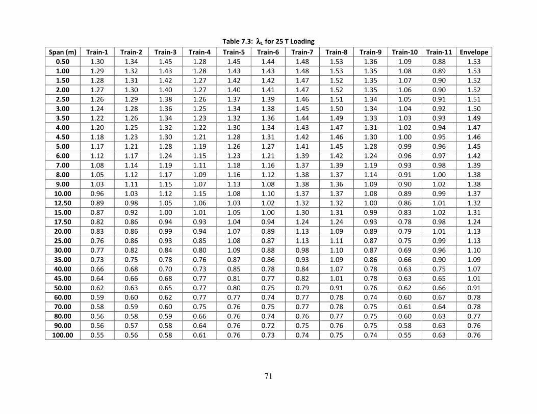
71
Table 7.3: λλλλ1 for 25 T Loading
Span (m) Train-1 Train-2 Train-3 Train-4 Train-5 Train-6 Train-7 Train-8 Train-9 Train-10 Train-11 Envelope
0.50 1.30 1.34 1.45 1.28 1.45 1.44 1.48 1.53 1.36 1.09 0.88 1.53
1.00 1.29 1.32 1.43 1.28 1.43 1.43 1.48 1.53 1.35 1.08 0.89 1.53
1.50 1.28 1.31 1.42 1.27 1.42 1.42 1.47 1.52 1.35 1.07 0.90 1.52
2.00 1.27 1.30 1.40 1.27 1.40 1.41 1.47 1.52 1.35 1.06 0.90 1.52
2.50 1.26 1.29 1.38 1.26 1.37 1.39 1.46 1.51 1.34 1.05 0.91 1.51
3.00 1.24 1.28 1.36 1.25 1.34 1.38 1.45 1.50 1.34 1.04 0.92 1.50
3.50 1.22 1.26 1.34 1.23 1.32 1.36 1.44 1.49 1.33 1.03 0.93 1.49
4.00 1.20 1.25 1.32 1.22 1.30 1.34 1.43 1.47 1.31 1.02 0.94 1.47
4.50 1.18 1.23 1.30 1.21 1.28 1.31 1.42 1.46 1.30 1.00 0.95 1.46
5.00 1.17 1.21 1.28 1.19 1.26 1.27 1.41 1.45 1.28 0.99 0.96 1.45
6.00 1.12 1.17 1.24 1.15 1.23 1.21 1.39 1.42 1.24 0.96 0.97 1.42
7.00 1.08 1.14 1.19 1.11 1.18 1.16 1.37 1.39 1.19 0.93 0.98 1.39
8.00 1.05 1.12 1.17 1.09 1.16 1.12 1.38 1.37 1.14 0.91 1.00 1.38
9.00 1.03 1.11 1.15 1.07 1.13 1.08 1.38 1.36 1.09 0.90 1.02 1.38
10.00 0.96 1.03 1.12 1.15 1.08 1.10 1.37 1.37 1.08 0.89 0.99 1.37
12.50 0.89 0.98 1.05 1.06 1.03 1.02 1.32 1.32 1.00 0.86 1.01 1.32
15.00 0.87 0.92 1.00 1.01 1.05 1.00 1.30 1.31 0.99 0.83 1.02 1.31
17.50 0.82 0.86 0.94 0.93 1.04 0.94 1.24 1.24 0.93 0.78 0.98 1.24
20.00 0.83 0.86 0.99 0.94 1.07 0.89 1.13 1.09 0.89 0.79 1.01 1.13
25.00 0.76 0.86 0.93 0.85 1.08 0.87 1.13 1.11 0.87 0.75 0.99 1.13
30.00 0.77 0.82 0.84 0.80 1.09 0.88 0.98 1.10 0.87 0.69 0.96 1.10
35.00 0.73 0.75 0.78 0.76 0.87 0.86 0.93 1.09 0.86 0.66 0.90 1.09
40.00 0.66 0.68 0.70 0.73 0.85 0.78 0.84 1.07 0.78 0.63 0.75 1.07
45.00 0.64 0.66 0.68 0.77 0.81 0.77 0.82 1.01 0.78 0.63 0.65 1.01
50.00 0.62 0.63 0.65 0.77 0.80 0.75 0.79 0.91 0.76 0.62 0.66 0.91
60.00 0.59 0.60 0.62 0.77 0.77 0.74 0.77 0.78 0.74 0.60 0.67 0.78
70.00 0.58 0.59 0.60 0.75 0.76 0.75 0.77 0.78 0.75 0.61 0.64 0.78
80.00 0.56 0.58 0.59 0.66 0.76 0.74 0.76 0.77 0.75 0.60 0.63 0.77
90.00 0.56 0.57 0.58 0.64 0.76 0.72 0.75 0.76 0.75 0.58 0.63 0.76
100.00 0.55 0.56 0.58 0.61 0.76 0.73 0.74 0.75 0.74 0.55 0.63 0.76

72
Table 7.4: λλλλ1 for 32.5 T Loading
Span (m) Train-1 Train-2 Train-3 Train-4 Train-5 Train-6 Train-7 Envelope
0.50 1.53 1.60 1.39 1.59 1.30 1.11 0.86 1.60
1.00 1.52 1.59 1.38 1.58 1.28 1.10 0.87 1.59
1.50 1.52 1.58 1.37 1.57 1.27 1.09 0.87 1.58
2.00 1.52 1.58 1.36 1.57 1.25 1.09 0.88 1.58
2.50 1.51 1.57 1.36 1.56 1.24 1.08 0.89 1.57
3.00 1.51 1.56 1.35 1.55 1.23 1.08 0.89 1.56
3.50 1.51 1.55 1.34 1.54 1.21 1.07 0.90 1.55
4.00 1.50 1.54 1.34 1.53 1.20 1.07 0.91 1.54
4.50 1.49 1.53 1.33 1.51 1.19 1.06 0.92 1.53
5.00 1.47 1.52 1.32 1.50 1.17 1.05 0.93 1.52
6.00 1.43 1.50 1.29 1.46 1.14 1.03 0.95 1.50
7.00 1.38 1.48 1.28 1.44 1.11 1.02 0.97 1.48
8.00 1.34 1.46 1.27 1.42 1.09 1.01 0.99 1.46
9.00 1.31 1.45 1.25 1.39 1.06 1.00 1.01 1.45
10.00 1.31 1.47 1.30 1.39 1.18 1.06 1.06 1.47
12.50 1.22 1.40 1.25 1.33 1.12 1.03 1.09 1.40
15.00 1.16 1.34 1.20 1.28 1.08 1.00 1.08 1.34
17.50 1.10 1.28 1.15 1.23 1.05 0.97 1.04 1.28
20.00 0.96 1.18 1.04 1.15 1.17 1.08 1.08 1.18
25.00 0.89 1.11 0.97 0.97 1.10 0.88 0.99 1.11
30.00 0.88 1.10 0.88 0.89 0.95 0.75 0.93 1.10
35.00 0.84 1.06 0.85 0.84 0.89 0.75 0.90 1.06
40.00 0.84 0.89 0.84 0.84 0.84 0.76 0.81 0.89
45.00 0.81 0.84 0.80 0.81 0.80 0.73 0.68 0.84
50.00 0.80 0.82 0.79 0.80 0.77 0.73 0.70 0.82
60.00 0.74 0.75 0.73 0.74 0.70 0.66 0.67 0.75
70.00 0.72 0.74 0.70 0.73 0.69 0.63 0.65 0.74
80.00 0.72 0.77 0.70 0.76 0.69 0.63 0.63 0.77
90.00 0.74 0.76 0.70 0.75 0.70 0.61 0.63 0.76
100.00 0.74 0.75 0.70 0.75 0.69 0.60 0.64 0.75
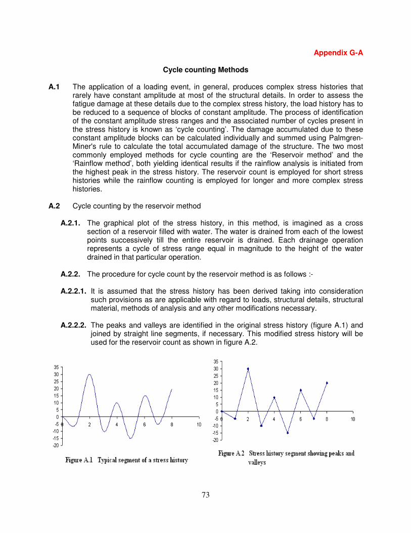
73
Appendix G-A
Cycle counting Methods
A.1 The application of a loading event, in general, produces complex stress histories that rarely have constant amplitude at most of the structural details. In order to assess the fatigue damage at these details due to the complex stress history, the load history has to be reduced to a sequence of blocks of constant amplitude. The process of identification of the constant amplitude stress ranges and the associated number of cycles present in the stress history is known as ‘cycle counting’. The damage accumulated due to these constant amplitude blocks can be calculated individually and summed using Palmgren-Miner's rule to calculate the total accumulated damage of the structure. The two most commonly employed methods for cycle counting are the ‘Reservoir method’ and the ‘Rainflow method’, both yielding identical results if the rainflow analysis is initiated from the highest peak in the stress history. The reservoir count is employed for short stress histories while the rainflow counting is employed for longer and more complex stress histories.
A.2 Cycle counting by the reservoir method
A.2.1. The graphical plot of the stress history, in this method, is imagined as a cross section of a reservoir filled with water. The water is drained from each of the lowest points successively till the entire reservoir is drained. Each drainage operation represents a cycle of stress range equal in magnitude to the height of the water drained in that particular operation.
A.2.2. The procedure for cycle count by the reservoir method is as follows :-
A.2.2.1. It is assumed that the stress history has been derived taking into consideration such provisions as are applicable with regard to loads, structural details, structural material, methods of analysis and any other modifications necessary.
A.2.2.2. The peaks and valleys are identified in the original stress history (figure A.1) and joined by straight line segments, if necessary. This modified stress history will be used for the reservoir count as shown in figure A.2.

74
A.2.2.3. A copy of the stress history is appended to the original (figure A.3) and the highest point (A) in the original segment and its counterpart (B) in the appended segment are marked and joined by a straight horizontal line. The portion of the stress history so enclosed will be used to represent the reservoir. In case there are two or more equal peaks in the original segment of the stress history then the first such peak will be considered along with its counterpart from the appended segment.
A.2.2.4. The reservoir is drained successively from the lowest points (E, F, D and C taken in order as shown in figure A.4) which retain water till the entire reservoir is emptied. Each drainage operation corresponds to a cycle of stress range equal in magnitude to the height of the water drained in that particular operation i.e. one
cycle of stress range σA - σE when drainage is from trough E.
A.2.2.5. The stress ranges and their associated number of cycles are sorted according to the magnitude of the stress ranges for further processing using the Palmgren-Miner criteria.
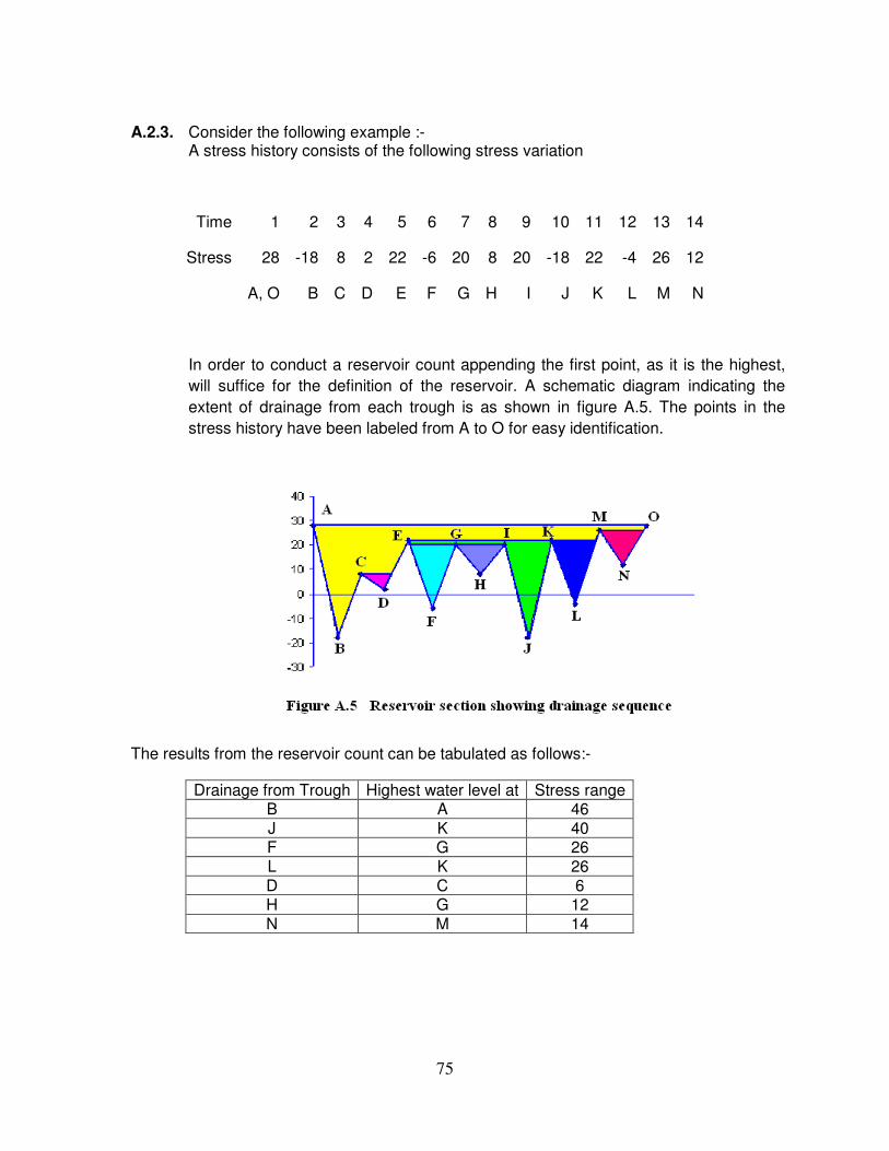
75
A.2.3. Consider the following example :-
A stress history consists of the following stress variation
Time 1 2 3 4 5 6 7 8 9 10 11 12 13 14
Stress 28 -18 8 2 22 -6 20 8 20 -18 22 -4 26 12
A, O B C D E F G H I J K L M N
In order to conduct a reservoir count appending the first point, as it is the highest,
will suffice for the definition of the reservoir. A schematic diagram indicating the
extent of drainage from each trough is as shown in figure A.5. The points in the
stress history have been labeled from A to O for easy identification.
The results from the reservoir count can be tabulated as follows:-
Drainage from Trough Highest water level at Stress range B A 46 J K 40 F G 26 L K 26 D C 6 H G 12 N M 14
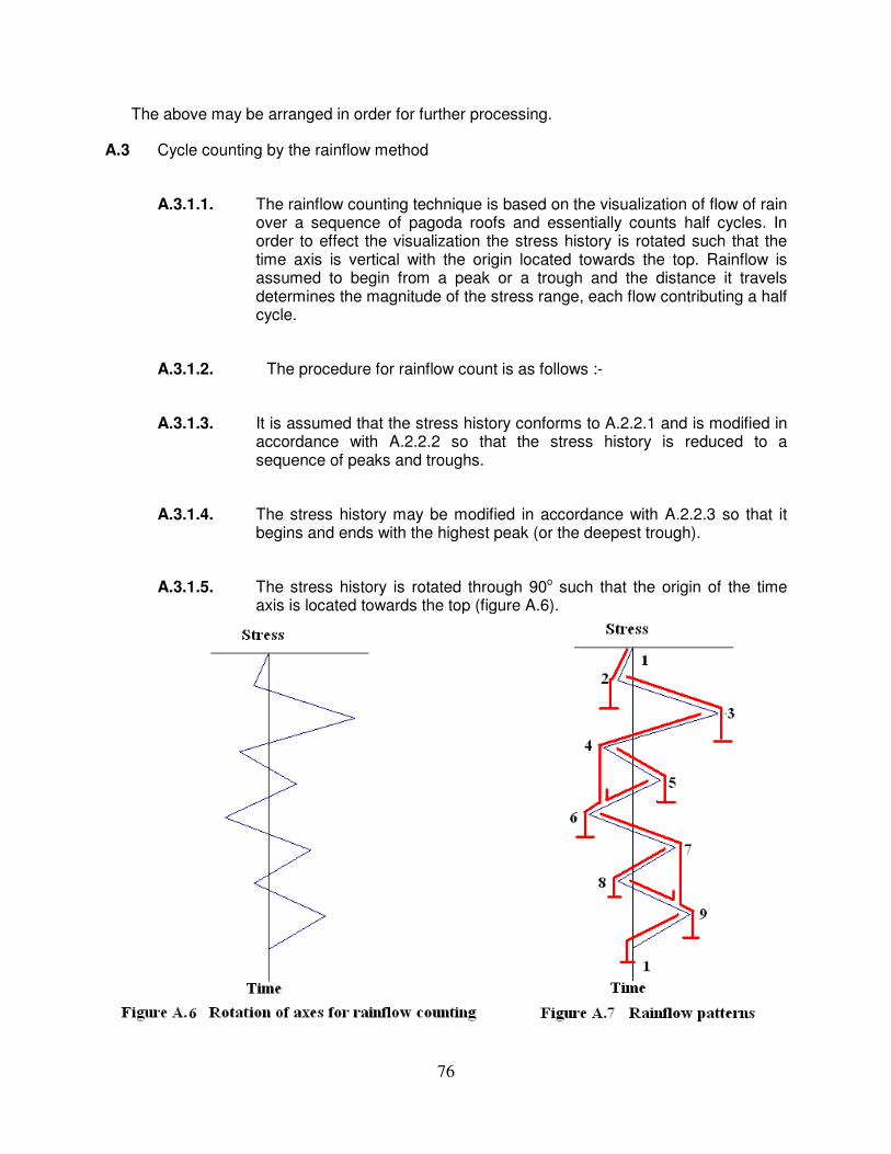
76
The above may be arranged in order for further processing.
A.3 Cycle counting by the rainflow method
A.3.1.1. The rainflow counting technique is based on the visualization of flow of rain over a sequence of pagoda roofs and essentially counts half cycles. In order to effect the visualization the stress history is rotated such that the time axis is vertical with the origin located towards the top. Rainflow is assumed to begin from a peak or a trough and the distance it travels determines the magnitude of the stress range, each flow contributing a half cycle.
A.3.1.2. The procedure for rainflow count is as follows :-
A.3.1.3. It is assumed that the stress history conforms to A.2.2.1 and is modified in accordance with A.2.2.2 so that the stress history is reduced to a sequence of peaks and troughs.
A.3.1.4. The stress history may be modified in accordance with A.2.2.3 so that it begins and ends with the highest peak (or the deepest trough).
A.3.1.5. The stress history is rotated through 90o such that the origin of the time axis is located towards the top (figure A.6).
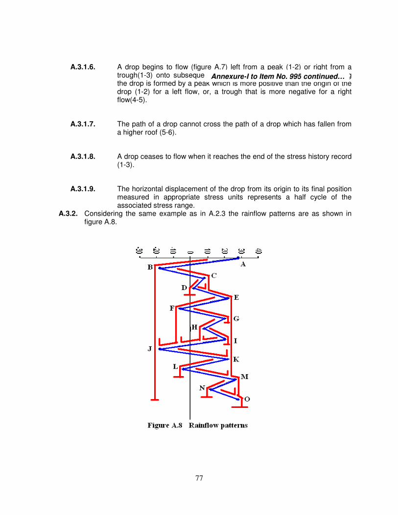
77
A.3.1.6. A drop begins to flow (figure A.7) left from a peak (1-2) or right from a trough(1-3) onto subsequent roofs (3-4-6) unless the surface receiving the drop is formed by a peak which is more positive than the origin of the drop (1-2) for a left flow, or, a trough that is more negative for a right flow(4-5).
A.3.1.7. The path of a drop cannot cross the path of a drop which has fallen from a higher roof (5-6).
A.3.1.8. A drop ceases to flow when it reaches the end of the stress history record (1-3).
A.3.1.9. The horizontal displacement of the drop from its origin to its final position measured in appropriate stress units represents a half cycle of the associated stress range.
A.3.2. Considering the same example as in A.2.3 the rainflow patterns are as shown in figure A.8.
Annexure-I to Item No. 995 continued…

78
The results from the rainflow count can be tabulated as follows:-
Origin of flow Termination of flow Half cycle stress range
A B 46
B O 46
C D 6
D C 6
E J 40
F G 26
G F 26
H I 12
I H 12
J K 40
K L 26
L K 26
M N 14
N M 14
The half cycles in the above may be combined and subsequently arranged in order for
further processing. It may be noted that the results of the rainflow and the reservoir counting
are identical in this case.

79
Appendix G-B
A note on the classification of structural details or connections
B.1 This appendix is applicable to Sections 9 and 10, including all references to classification of the structural connection or detail contained in equations, figures or tables. This appendix is included to explain the basis of classification of the structural connection or details and to indicate the differences in the fatigue strength which arise due to the
adoption of the rounded values of the reference fatigue strength ∆σC.
B.2 The classification into detail categories is based on statistical analysis of fatigue data obtained from laboratory tests.
B.3 Three failure criteria are generally considered for laboratory fatigue testing of specimens:
- First appearance of a crack either detected visually or detected by physical means - Through-thickness crack: the fatigue crack starts from the front surface and grows
through the thickness of the test piece and reaches the back surface. - Complete fracture of the tested specimen or large displacement of the tested
structural element such that the displacement becomes critical so that the applied "jack load" cannot be maintained.
The adopted classification is based on the last criteria.
B.4 The classification of a given detail, either welded or bolted, results from a statistical evaluation of the fatigue test data with a 95% probability of survival for a 75% confidence interval.
B.5 The main provisions for fatigue assessment are based upon a set of fatigue resistance curves, equally spaced which form a basis for the classification of constructional details. The concept for fatigue strength design is based on a set of equally spaced fatigue strength curves with a constant slope of m = 3 (for normal stress), or m = 5 (for shear stress and some other details). Another concept duly incorporated is the geometrical stress concentration concept (also called the "hot spot stress" method).
B.6 The specification of the S-N curves is based on a “grid system” which is established by dividing the difference between one order of magnitude of stress ranges at a reference
value of endurance into 20 equal spaces i.e. the spacing between ∆σC =100 MPa and
∆σC =1000 at 2 million cycles is divided into 20 intervals providing different classification

80
S-N curves with the same slope as shown in figure B.1 for nominal normal or direct stresses.
B.7 Considering nominal direct or normal stresses, in accordance with clause B.6 i.e.
considering ∆σC =100 MPa and ∆σC =1000 at 2 million cycles as shown in figure B1
log N = log a – 3* log ∆σ
(10.2.2)
can be expressed alternatively as
log a = log N + 3 * log ∆σ
∴ when ∆σC = 1000 MPa log a = 6.30103 + 3 * 3.0 = 15.30103
and ∆σC = 100 MPa log a = 6.30103 + 3 * 2.0 = 12.30103
hence ∆log a = (15.30103 – 12.30103)/20 = 0.15
2.106
100 MPa
log ∆∆∆∆σσσσR
Figure B.1 Spacing of fatigue strength curves for direct stress ranges
(m = 3 for both curves)
log N
1000 MPa
} 20 equal divisions

81
The successive values of log a, incrementing or decrementing by ∆log a each time, yield
corresponding values of ∆σ from the following:
log ∆σ = (log a - log N)/3
in which the substitution of N = 2 million cycles yields log ∆σC.
B.8 Considering nominal shear stresses, in accordance with clause B.6 i.e. considering ∆τC
=10 MPa and ∆τC =100 at 2 million cycles and m = 5,
log N = log a – 5 * log ∆τ
(10.2.2)
can be expressed alternatively as
log a = log N + 5 * log ∆τ
∴ when ∆τC = 100 MPa log a = 6.30103 + 5 * 2.0 = 16.30103
and ∆τC = 10 MPa log a = 6.30103 + 5 * 1.0 = 11.30103
hence ∆log a = (16.30103 – 11.30103)/20 = 0.25
The successive values of log a, incrementing or decrementing by ∆log a each time, yield
corresponding values of ∆τ from the following:
log ∆τ = (log a - log N)/5
in which the substitution of N = 2 million cycles yields log ∆τC.
B.9 The numerical values for fatigue strength for normal stress ranges on the basis of clause B.7 are indicated in Table 10.1A (see clause 10.2.3). The adopted value of the detail category is for information only.
B.10 The numerical values for fatigue strength for shear stress ranges on the basis of clause B.8 are indicated in Table 10.2A (see clause 10.2.4). The adopted value of the detail category and values corresponding to log a = 16.051 is for information only.
B.11 The numerical values for modified fatigue strength curves for normal stress ranges on the basis of clauses 10.3.3 and B7 are indicated in Table 10.3A. The adopted value of the detail category and values corresponding to log a = 11.251 and 10.951 is for information only.
B.12 The tables 10.1A, 10.2A and 10.3A may be used instead of tables 10.1, 10.2 and 10.3 but this should be clearly stated and the tables used in a consistent manner.
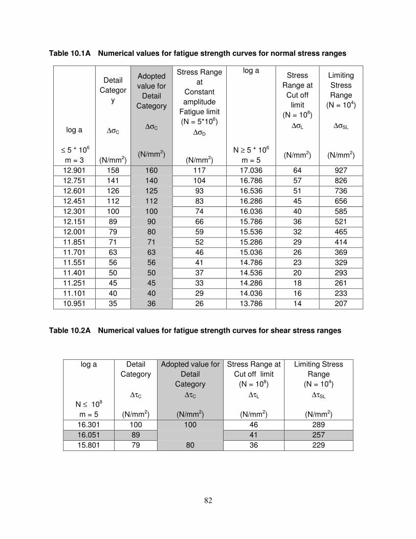
82
Table 10.1A Numerical values for fatigue strength curves for normal stress ranges
log a
≤ 5 * 106
m = 3
Detail
Categor
y
∆σC
(N/mm2)
Adopted
value for
Detail
Category
∆σC
(N/mm2)
Stress Range
at
Constant
amplitude
Fatigue limit
(N = 5*106)
∆σD
(N/mm2)
log a
N ≥ 5 * 106
m = 5
Stress
Range at
Cut off
limit
(N = 108)
∆σL
(N/mm2)
Limiting
Stress
Range
(N = 104)
∆σSL
(N/mm2)
12.901 158 160 117 17.036 64 927
12.751 141 140 104 16.786 57 826
12.601 126 125 93 16.536 51 736
12.451 112 112 83 16.286 45 656
12.301 100 100 74 16.036 40 585
12.151 89 90 66 15.786 36 521
12.001 79 80 59 15.536 32 465
11.851 71 71 52 15.286 29 414
11.701 63 63 46 15.036 26 369
11.551 56 56 41 14.786 23 329
11.401 50 50 37 14.536 20 293
11.251 45 45 33 14.286 18 261
11.101 40 40 29 14.036 16 233
10.951 35 36 26 13.786 14 207
Table 10.2A Numerical values for fatigue strength curves for shear stress ranges
log a
N ≤ 108
m = 5
Detail
Category
∆τC
(N/mm2)
Adopted value for
Detail
Category
∆τC
(N/mm2)
Stress Range at
Cut off limit
(N = 108)
∆τL
(N/mm2)
Limiting Stress
Range
(N = 104)
∆τSL
(N/mm2)
16.301 100 100 46 289
16.051 89 41 257
15.801 79 80 36 229

83
Table 10.3A Numerical values for modified fatigue strength curves for normal stress
ranges
log a
N ≤ 5 * 106
m = 3
Detail
Category
∆σC
(N/mm2)
Adopted
value for
Detail
Category
∆σC
(N/mm2)
Stress Range
at
Constant
amplitude
Fatigue limit
(N = 5*106)
∆σD
(N/mm2)
log a
N ≥ 5 * 106
m = 5
Stress Range
at Cut off
limit
(N = 108)
∆σL
(N/mm2)
Limiting
Stress
Range
(N = 104)
∆σSL
(N/mm2)
11.551 56 50*(56) 33 14.585 21 329
11.401 50 45*(50) 29 14.335 18 293
11.251 45 26 14.085 16 261
11.101 40 36*(40) 23 13.835 15 233
10.951 35 21 13.585 13 207
CS 18 Dtd 14.6.12

APPENDIX H
Distribution of Wheel Loads on Steel Troughing or Beams Spanning Transversly to the Track.
When the running rails are supported directly on steel troughing or beams spanning transversely between the main girders, the pitch of the troughing or beams being, as it normally will be, less than half the axle spacing, the deflection of the rails, and the resulting stresses in the troughing or beams, may be calculated on the assumption that the rails have a uniform elastic support. The method of calculation is as follows:
The deflectionδ of the rail seat due to a uniform load of 1 tonne per linear metre on each rail is first calculated, from the bending moment diagram and the moment of inertia of the troughing or beams supporting the rail. Then the “elastic modulus” of the track i.e. weight in kilograms per linear cm on each rail required to depress it one cm, represented by the symbol “U” is given by the formula:
δδ10
x 1001000 U ==
Now let I = the moment of inertia of each rail, about a horizontal axis, in cm4 .
Y0 = the depression of the rail in cm immediately below a load P tonnes.
And X1 = the distance from the load to the point of contra flexure of the rail in cm. Then X1 = 42.3 4 /UI
Yo =4 3
3.9IU
P =
1
393UX
P
The second of these formulae gives the deflection of the rail, and so the bending
stress in the transverse troughing or beam, immediately under an axle. The effect of adjacent axles is calculated by means of the Master Diagram on page 76 which gives the relative depression due to an axle load at a distance X1 cm.
In the above calculations, the load P is the wheel load of the locomotive with dynamic effect as per clause 2.4.1 (E) of IRS Bridge Rules.
The following example will illustrate the method
Steel transverse sleepers or steel channel sleepers with a moment of inertia of 1558.8 cm4and a section modulus of 207.8 cm3. at 74 cm centres, supported on main girders at 1.98m centres carry new 90R rails, having moment of inertia of 1600 cm4. What is the stress in the sleepers under modified broad gauge loading 1987.
Assume E = 21100 kg/mm2
Solution: The load applied to a sleeper by each rail due to a load of 1 tonne per metre
on the rail is 0.74tonne.
IVA-73
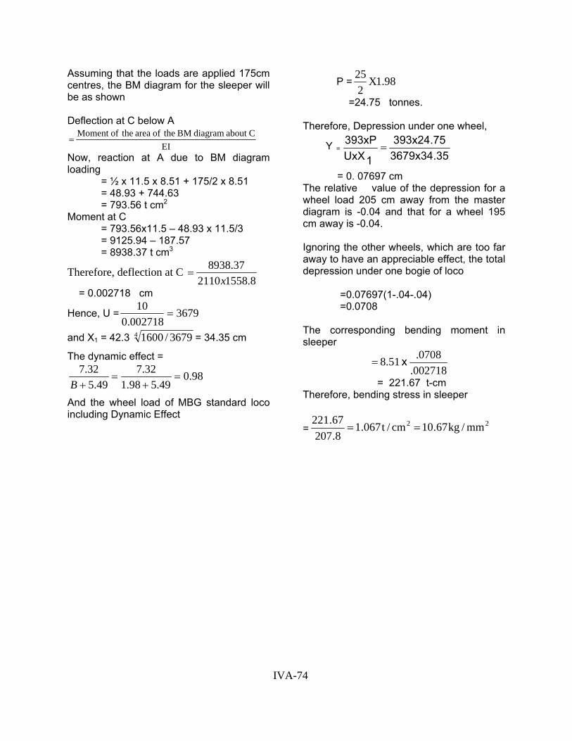
Assuming that the loads are applied 175cm centres, the BM diagram for the sleeper will be as shown
Deflection at C below A
EICabout diagram BM theof area theofMoment =
Now, reaction at A due to BM diagram loading
= ½ x 11.5 x 8.51 + 175/2 x 8.51 = 48.93 + 744.63 = 793.56 t cm2
Moment at C = 793.56x11.5 – 48.93 x 11.5/3 = 9125.94 – 187.57 = 8938.37 t cm3
Therefore, deflection at C 8.15582110
37.8938x
=
= 0.002718 cm
Hence, U = 3679002718.0
10=
and X1 = 42.3 4 3679/1600 = 34.35 cm
The dynamic effect =
98.049.598.1
32.749.5
32.7=
+=
+B
And the wheel load of MBG standard loco including Dynamic Effect
P = 98.1X225
=24.75 tonnes.
Therefore, Depression under one wheel,
Y = 3679x34.35393x24.75
1UxX393xP
=
= 0. 07697 cm The relative value of the depression for a wheel load 205 cm away from the master diagram is -0.04 and that for a wheel 195 cm away is -0.04.
Ignoring the other wheels, which are too far away to have an appreciable effect, the total depression under one bogie of loco
=0.07697(1-.04-.04) =0.0708
The corresponding bending moment in sleeper
002718.0708.51.8 x =
= 221.67 t-cm Therefore, bending stress in sleeper
= 22 mm/kg67.10cm/t067.18.207
67.221==
IVA-74

IVA-75

APPENDIX J Recommendation for the design of combined Road-Rail Bridges
1. These recommendations relate tothe design of bridge girders carrying both road and rail traffic. Bridges in which separate road and railway spans are carried on common piers are not dealt with. Relevant Road way Standard should be consulted wherever necessary.
2. Type of combined bridges: -Combined bridges may be classified, according to the relative positions of the road and railway as follow
TYPE USEA. Road and railway
on same deck Only for bridges carrying unimportant branch lines and roads with comparatively light traffic.
B. Road and railway side by side, above or between main girders.
Not recommended on account of eccentric loading, but may be considered for short bridges, on which only a single traffic-lane road is required, and where road and railway are at nearly the same level.
C. Cantilevered roads.
For short bridges in flat country, where either road or railway would have to be ramped up to take it over the other. For bridges of medium lengths, relative economy of type C and E should be examined.
D(1) Railway above road and over top chords.
For bridges with spans up to about 76.2 m(250 ft) clear in hilly country, where track level would not have to be raised appreciably to give required clearance from high flood level.
D(2) Railway above road and between girders.
As for D(1) but for longer spans. Type D(1) would be used for longer spans probably up to 91.40 m (300 ft) clear, in double track bridges to avoid increasing the spacing of main girders, provided rail level is suitable.
E(1) Road above railway and over top chords.
For long bridges in flat country, with spans up to about 61.0 m to 91.40 m (200 ft to 300 ft) depending on (a) the total length of the bridge,(b) the number and gauge of the tracks ,and (c) the width of the roadway.
E(2) Road above railway and between girder.
As for E(1), but for cases where it is more economical to accommodate the roadway between the main girders than to raise it sufficiently to enable it to project above the top chords.
IVA-76

Note: - (1) The various limiting span lengths given above are based on judgment only and not on actual designs. Comparative designs for two or more types should be made in all borderline cases to determine the most economical type. (2) Type A bridges are very undesirable from the point of view of track maintenance, Railway operation and road traffic. New bridges of this type should, therefore, be constructed only in very exceptional circumstances. (3)`Type C combined bridges, having two single traffic-lane roads carried on cantilevers outside the main girders, have two great disadvantages,(a) fast traffic cannot pass slow
traffic on the bridge, and (b) the eccentricity of loading, with only one traffic-lane loaded, requires a lot of extra metal in the main girders, especially when IRC class “AA” load is specified. Bridges of this type should, therefore, be used only for very short crossings.
3. Depth of Main girders and system of Triangulation
3.1 For spans of types A, B, C, D (2) and E(2) the economic depth of the main girders will probably be about one seventh of the span. A ‘K’ system of triangulation with polygonal top chords will generally be most suitable for bridges of these types with
For types A, B & C
LEVE
L O
F U
PPER
DEC
K
LEVE
L O
F U
PPER
DEC
K
For types D(2) & E(2) with lateral bracings between top chords.
For types D(2) & E(2) without lateral bracings between top chords.
clear spans or 91.4m(300 ’) or over, but for 106.7m (350’) clear spans of types D(2) and E(2) fitted with lateral bracings between the top chords the possible variation in depth of the girders would not be large, and parallel chords will probably prove more economical. 3.2 For spans of types D (1) and E (1) parallel chords will be necessary, and where the road or railway has to climb to the level of the top chords, a reduction in the ratio of depth to length of span, or in the length of span itself, below the economic figures for bridges carrying railway loads
only, may be found to give the minimum total cost of the bridge. 3.3 ‘K’ trusses will generally be more economical than ‘N’ or warren truss for spans of 91.4m (300’) or over, though this limit may be somewhat increased where trough-decking is used and the panel length increased. The arrangement of the members of ‘K’ trusses at the ends of the spans shown below will generally be the most suitable under the conditions shown against each.
IVA-77

4. Layout of approach roads
4.1 Types A-D. No special arrangements will have to be made in the case of types A, B and C except that level crossing gates will have to be provided at each end of a bridge of type A, while for a bridge of Type C one-half of the road will have to cross the railway at each end of the bridge by means of a level crossing and under-bridge or an over-bridge. In the case of types D and E the road will have to diverge from the railway at each end of the bridge, approach spans will be required for this purpose and the design of these must be such as to give reasonably good conditions for road traffic. The approach spans for bridges of types D will carry the railway and will, of course, be on the same alignment as the main spans. Their length will be governed by the condition that it must be possible to construct a roadway approach curve, clear of the approach span abutment, which can be traversed by road vehicles at the design speed.
4.2 Type E. in the case of Bridges of Type E the approach spans will carry the road way and their length will be controlled by the angle of divergence between the road and the railway and by the condition that the pier or tower supporting the end farther from the main span must clear the railway fixed structure diagram.
5 The design of the road approaches between the end of the main bridge and a point at which the distance between the road and railway is sufficient to accommodate and embankment shall be made by the railway, in consultation with the road authority. The construction and maintenance of railway approach spans (type D bridges) and of piers or abutments carrying such spans will be the responsibility of the railway authority.
The design, construction and maintenance of roadway approach spans (type E bridges), which are over or partly over the railway, will be the responsibility of the railway authority. The design, construction and maintenance of other roadway approach spans, including pier and abutment, or of steel trestles or arch viaducts carrying in approach road may be undertaken by either the railway or the road authority, as mutually agreed in each case.
6. Handrailings or parapets
6.1 The clear distance from the lower rail to the top of the kerb shall not exceed 150mm (6 inches) unless the space if filled by vertical or inclined members, the clear distance between which is not more than 150mm (6 inches). The strength of the lower rail shall be at least as great as that of the top rail. The space between the lower rail and the top rail shall be filled by means of vertical, horizontal or inclined members, the clear distance between which shall be fixed with due regard to the safety of persons and animals using the structure.
6.2 In cases where a road vehicle mounting the kerb and breaking through the hand railing or parapet may endanger the stability of the bridge, the railway authority may require the height of the kerb, or the strength of the hand railing (or parapet) or both, to be suitably increased.
IVA-78