indirect drive in-wheel system for hev/ev traction indirect drive in-wheel system for hev/ev...
TRANSCRIPT

EVS27
Barcelona, Spain, November 17 - 20, 2013
Indirect Drive In-Wheel System for HEV/EV Traction
Y. Tang1, J. J. H. Paulides, I. J. M. Besselink2, F. Gardner3, E. A. Lomonova1Electromechanics and Power Electronics Group, Department of Electrical Engineering,
Eindhoven University of Technology,
Den Dolech 2, 5612 AZ Eindhoven, the Netherlands, [email protected] and Control Group, Department of Mechanical Engineering,
Eindhoven University of Technology3Teamwork Technology B.V., the Netherlands
Abstract
In-wheel traction allows simplicity and freedom for the design of hybrid-electric/electric vehicle
(HEV/EV). However, the in-wheel motor increases the unsprung mass and hence deteriorates ride com-
fort and reduces the road holding capability of the car. To solve these problems, this paper proposes an
indirect drive in-wheel traction system including a light-weight in-wheel drive and a specially designed
rear suspension. A prototype of the in-wheel drive is designed based on the vehicle model of Volkswa-
gen (VW) Lupo 3L. The prototype analysis shows that the proposed in-wheel system gives a balanced
distribution of the vehicle weight and thus improves ride comfort. Design principles of the electrical mo-
tor used for this in-wheel system is further investigated. By reducing the permanent magnet height, the
field weakening capability of a 24-slot 8-pole surface permanent magnet synchronous motor is visibly
improved.
Keywords: in-wheel traction, rear suspension, unsprung mass, motor design, field weakening
1 Introduction
With the rising concern on environmental is-sues, hybrid/electric vehicles (HEV/EV) haveattracted an increasing interest from public andindustry since the end of 20th century. The fastdeveloping technology of HEV/EV has alsointroduced a revolutionary traction concept tovehicles designers, namely in-wheel traction.By putting electrical motors in the wheels, thedrivetrain is greatly simplified. Mechanical axescan thus be removed, which creates extra spacefor the cargo and reduces the total weight ofthe vehicle [1], [2] (Fig. 1a). These advantagesof simplicity and freedom make the in-wheeltraction a preferable traction mode for vehicledesigners.
Research and development of advanced in-wheelmotors and in-wheel traction systems are thusintensively carried out [3], [4], [5], [6]. The com-
pany E-Traction designed a direct drive outer-
rotor motor, namely TheWheelTM (Fig. 1b) [7].Protean Electric developed an in-wheel elec-tric drive system, namely ProteanDrivetm
(Fig. 1c) [8]. Ford and Schaeffler demonstrated
a Fiesta-based eWheelDriveTM car powered byindependent electric motors in each of the rearwheels (Fig. 1d), together delivering 40kW, peakand 33kW, continuous power [9].
However, in most existing in-wheel tractionsystems, the electrical motor is directly drivingthe wheel, as shown in Fig. 1b. This direct driveconcept of the in-wheel traction greatly raisesthe torque requirement for the electrical motordesign. At certain operation points, such ascurb climbing, the torque requirement becomesuneconomical or even impractical and thuslimits the vehicle performance. In addition, hightorque requirement leads to the requirement oflarge volume for the in-wheel motor, resulting in
EVS27 International Battery, Hybrid and Fuel Cell Electric Vehicle Symposium 1

(a) (b)
(c) (d)
Figure 1: In-wheel traction - a) An electric
truck with large cargo; b) TheWheelTM, ETrac-
tion; c) ProteanDriveTM, Protean Electric; d)
eWheelDriveTM, Ford and Schaeffler
large additional unsprung mass. The increasedunsprung mass can be problematic because itpotentially deteriorates ride comfort and reduceroad holding capability of the car [10].
Problems caused by large unsprung mass are fur-ther explained in Section 2. To improve the vehi-cle performance of HEV/EV with in-wheel trac-tion, this paper proposes an indirect drive in-wheel traction system including a light-weightin-wheel drive and a specially designed rear sus-pension system, based on the vehicle modelof VW Lupo 3L. The structure of this light-weight in-wheel drive is described in Section 3,in which the electrical motor is indirectly drivingthe wheel through a gearbox. By this means therequired torque for the motor is reduced and themass of the in-wheel drive is minimized. Princi-ples of selection and design of the electrical mo-tor for the proposed in-wheel drive is discussedin Section 4. A special design of the rear suspen-sion system is further introduced in Section 5.
2 Problems of in-wheel traction
Problems of in-wheel traction due to the in-creased unsprung mass is revealed by the oscil-lation model of an electrical vehicle, as shown inFig. 2. In this model, the vehicle mass above thesuspension system is represented as sprung mass,while the mass below the suspension system isrepresented as unsprung mass. When the un-sprung mass increases, the unsprung-to-sprungmass ratio increases. Variation of this ratio leadsto changes in three criteria used for assessing thevehicle performance, which are:
• The transmissibility ratio
– the response of the sprung mass to theexcitation from the road
– used for assessing the ride comfort ofa vehicle
• The suspension travel ratio
– the ratio of the maximum relative dis-placement between the sprung and un-sprung mass to the amplitude of theroad input
– used for assessing the space re-quired to accommodate the suspensionspring.
• The dynamic tyre deflection ratio
– the ratio of the maximum relative dis-placement between the unsprung massand the road surface to the amplitudeof the road input
– used for assessing the handling andsafety of the vehicle.
Sprung mass
Unsprung mass
Suspension
system
Tyre
(a) (b)
Figure 2: Oscillation model of quarter car -
a)eWheelDriveTM with wheel suspension; b) oscil-
lation model
The general effect of an increased unsprung-to-sprung mass ratio on the three criteria areshown in Fig. 3. In the frequency range betweenthe natural frequency of the sprung mass andthat of the unsprung mass, all three criteriaincreases with the unsprung-to-sprung massratio increases. This suggests a reduced ridecomfort, an increased accommodation space forthe suspension spring, and an increased difficultyin handling the vehicle [11].
To solve the problems caused by increased un-sprung mass, several companies proposed anddeveloped various in-wheel drives that containactive suspension systems, such as the activewheel drive in-wheel motor of Michelin (Fig. 4a)[12] and the eCorner of Siemens (Fig. 4b)[13]. Moreover, Bridgestone invented a dynamicdamping in-wheel drive, in which the shaftlessmotor is suspended using flexible coupling. Itis claimed that by this means the vibration in-put from the road irregularities is cancelled by
EVS27 International Battery, Hybrid and Fuel Cell Electric Vehicle Symposium 2

(a) (b) (c)
Figure 3: Effect of unsprung-to-sprung mass ratio on:
a) the transmissibility ratio; b) the suspension travel
ratio; c) the dynamic tyre deflection ratio. [11]
the vibration of the motor, resulting in an im-proved road-holding performance and ride com-fort (Fig. 4c) [14]. However, active suspen-sion consumes energy, which is scarce in a bat-tery electric vehicles (BEV). Besides, full elec-tric active suspensions are not yet well developedand usually heavy, while hydraulic active suspen-sions are less compatible with EVs.
(a) Michelin active wheel (b) Siemens eCorner
(c) Bridgstone’s dynamic-damping in-wheel drive
Figure 4: Advanced in-wheel drives dealing with the
problem of increased unsprung mass
3 Light-weight in-wheel drive
A light-weight in-wheel drive is proposed tominimize the unsprung mass of HEV/EV within-wheel traction, shown in Fig 5a. In thisdrive, the electrical motor is indirectly drivingthe wheel through a gearbox, thus the requiredtorque for the electrical motor is reduced, shownin Fig 5b, leading to reduction on the motorvolume and mass.
Lateral link Damper
Spring
Wishbone
Motor
Cable
Required rotor speed
Req
uir
ed t
orq
ue
Indirect driving
Direct driving
n1
n2
T2
T1
(a) (b)
Figure 5: Light-weight in-wheel drive a) the struc-
ture and b) torque-speed requirements for electrical
motors in direct drive and indirect drive in-wheel trac-
tion systems.
A prototype (Fig. 6a) is designed and manufac-tured based on the specification of VW Lupo3L (Fig. 6b), in which the gear ratio is 14.76.Parameters of this car are summarized in Ta-ble. 1. The car is driven by two in-wheel drivesin the rear wheels. Based on this design, thetorque and speed requirements for the electricalmotor of this indirect drive in-wheel systemare compared to that in a direct drive in-wheelsystem, shown in Table 2. It can be seen thatby implementing the gearbox, the requiredtorque of the electrical motor is significantlyreduced. It is also shown that the maximumpower of this VW Lupo 3L is comparable tothe Fiesta-based eWheelDrive car developed byFord and Schaeffler. Therefore, it is reasonableto compare the masses of the two different drives.
Table 1: Vehicle parameters of VW Lupo 3L
Description Symbol Value
Total mass (including driver) m 1100kg
Wheel diameter Dw 0.556m
Frontal vehicle area SF 1.97m2
Kinetic friction coefficient µ 0.0085
Drag coefficient CD 0.29
Maximum mechanical power Pmax 40kW
In the demonstrated Fiesta-based eWheelDrivecar, the total mass of the wheel hub drive is53kg. While the total mass of the prototypeof this light-weight in-wheel drive is 31.5kg, inwhich the mass of the motor is 13.8kg. There-fore, the proposed drive is 40.6% lighter than theeWheelDrive.
4 Electrical motor design
4.1 Electrical motor type selection
The electrical motor designed for this light-weight in-wheel drive needs to have a high torque
EVS27 International Battery, Hybrid and Fuel Cell Electric Vehicle Symposium 3

Table 2: Torque-speed requirements for the in-wheel motor in different drive modules
Corner casesDirect driving Indirect driving
Power P (kW)Torque T (Nm) Speed n (rpm) Torque T (Nm) Speed n (rpm)
140km/h @ 0% 85.0 1336 5.8 19717 11.9
130km/h @ 0% 75.0 1240 5.1 18309 9.7
80km/h @ 10% 187.0 763 12.7 11267 14.9
50km/h @ 15% 246.5 477 16.7 7042 12.3
15km/h @ 30% 448.0 143 30.4 2113 6.7
0 - 100 km/h (14s) 494.5 0 - 954 33.5 0 - 14084 0 - 20
(a) Prototype (b) VW Lupo 3L
Figure 6: Prototype of the light-weight in-wheel drive
for Volkswagen Lupo 3L.
density with a wide constant power speed range(CPSR). Table 3 shows the torque density andspeed ratio of different types of electrical mo-tors [15]. It can be seen that permanent mag-net synchronous motor (PMSM) has the highesttorque density and thus is a strong candidate forthis application.
Torque
Power
Constant power speed range (CPSR)
SpeedSpeed
Max. speedMax. speed
Max. torqueMax. torque
Speed ratio x = Base speed / Max. speedSpeed ratio x = Base speed / Max. speed
Base speedBase speed
Figure 7: Constant power speed region of an electrical
motor.
Table 3: Torque densities for different motor types
Machine typeTorque density
(Nm/m3)
Permanent magnet syn-
chronous motor
28860
Induction motor 4170
Switched reluctance motor 6780
4.2 PMSM design for wide CPSR
However, CPSR of PMSM is highly dependingon the field weakening capability, which isinherently decided by the motor design. In thePMSM design, two parameters are related tothe fielding weakening capability, which arethe normalised PM flux linkage Ψmn and thesaliency ratio ξ [17].
One the one hand, the normalised PM flux link-age Ψmn is calculated as:
Ψmn =Ψm
Ψb
, (1)
in which Ψm is the flux linkage produced bypermanent magnet and Ψb is the total fluxlinkage at the base speed, as indicated in Fig. 8.A high saliency ratio
Figure 9 shows the relation between the nominalrotor speed ωn and the nominal output power Pnwith different values of the permanent magnetflux linkage Ψmn. It can be seen that the max-imum CPSR is achieved when Ψmn is smallerthan 0.71.
On the other hand, the saliency ratio ξ is definedas:
ξ =Ld
Lq
, (2)
in which Ld and Lq are inductances in the direct-and quadrature-axis.
In PMSM, the electromagnetic torque can be cal-culated as:
Tem =3p
2[Ψmiq − (Ld − Lq)idiq] (3)
=3p
2[Ψmiq − (ξ − 1)Ldidiq], (4)
in which the first term in the square bracketrepresents the Lorentz torque component and thesecond term is the reluctance torque component.
During the field weakening, the Lorentz torquereduces due to reduction on iq. However, due
EVS27 International Battery, Hybrid and Fuel Cell Electric Vehicle Symposium 4

2
b m q q( )y = y + L i
my
q qL i
0 d
q
(a) Non-salient PMSM
my
q qL i
d dL i0
2 2
b m d d q q( ) ( )y = y + +L i L i
d
q
(b) Salient PMSM
Figure 8: Phasor diagram of flux linkages in perma-
nent magnet synchronous motors.
Figure 9: Impact of the nominal PM flux linkage Ψmn
on the constant power speed range of permanent mag-
net synchronous motors.
to the appearance of a negative d-axis current,i.e. id < 0, the reluctance torque increases whenξ < 1, i.e. Lq < Ld and thus compensatesthe reduced Lorentz torque. This compensationeffect can be enhanced with increasing thesaliency ratio ξ, hence the CPSR is extended.
Therefore, from the design point of view, thefield weakening capability of PMSM can be im-proved in following aspects:
• Saliency Salient machines usually give ahigh saliency ratio. This ratio can be fur-ther increased using specific design for therotor structure.
• Magnet height By reducing the height ofmagnet poles, the PM flux linkage can be
reduced, hence the nominal PM flux linkageis also reduced, leading to a wider CPSR.
• Winding topology Compared to distributedwindings, machines with concentratedwindings have considerably higher induc-tance, mainly due to higher slot leakage,hence a higher rated flux linkage and alower nominal PM flux linkage. Therefore,they have a wider CPSR.
4.3 Design optimization
In this paper, the design methods in extendingthe CPSR of PMSM are used to optimize thedesign of a 24-slot 8-pole surface PMSM, shownin Fig. 10 for the proposed light-weight in-wheeldrive. The original design of this PMSM,denoted as MI, is summarized in Table 4.
Stator
Permanent
magnets
Rotor
back iron
Rotor sleeve
(a) (b)
Figure 10: Design layout of the 24-slot 8-pole perma-
nent magnet synchronous motor: a) 3D structure; b)
Cross-section.
Table 4: Motor parameters
Description Symbol Value Unit
Stator slot number Ns 24 -
Rotor pole number p 8 -
Coil turn numberNt 12 -
(per slot)
Stack length L 76.4 mm
Stator outer diameter Dso 127.3 mm
Rotor outer diameter Dro 69.1 mm
Airgap length δ 3.0 mm
Magnet height hm 6.0 mm
The torque-speed characteristic of this designat 150V supply voltage is shown in Fig. 11. Togenerate the maximum required torque, 88Acurrent is needed. This current requirement canbe reduced by increasing the number of coilturns in a stator slot Nt. When Nt is doubled to12 turns, the required current for the maximumtorque is reduced to 44A, which is half of thatin MI. However, in this case the base speed isalso reduced to half of the original value as the
EVS27 International Battery, Hybrid and Fuel Cell Electric Vehicle Symposium 5
induced back-EMF is doubled.
Figure 11: Torque-speed characteristics of the perma-
nent magnet synchronous motor in different design
versions MI, MII, and MIII.
The advantage of this adapted version of design,denoted as MII, is that the sizes of the batteryand power electronics modules are reduced.However, the problem is that with 150V supplyvoltage and 44A phase current, this designcannot meet the torque-speed requirements forthe operation points above the base speed. Evenwhen the phase current is increased to 60A, thetorque-speed profile of MII still cannot coverthe two operation points at maximum vehiclespeeds, as the blue dot-dashed curve shows inFig 11. This implies room to improve the fieldweakening capability of this design.
A simple method without changing the windingtopology and rotor structure is adjusting the mag-net height hpm. By reducing hpm from 6mm to3.5mm, the new version of design, denoted asMIII, provides a torque-speed profile that is ableto cover all required operation points with 150Vsupply voltage and 60A phase current, as the redsolid curve shows in Fig. 11.
5 Rear suspension design
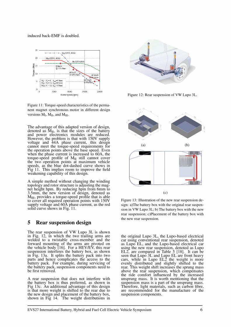
The rear suspension of VW Lupo 3L is shownin Fig. 12, in which the two trailing arms arewelded to a twistable cross-member and theforward mounting of the arms are pivoted onthe vehicle body [16]. For a HEV/EV, this rearsuspension interferes the battery box, as shownin Fig. 13a. It splits the battery pack into twoparts and hence complicates the access to thebattery pack. For example, during servicing ofthe battery pack, suspension components need tobe first removed.
A rear suspension that does not interfere withthe battery box is thus preferred, as shown inFig 13c. An additional advantage of this designis that more weight is shifted to the rear due tothe new design and placement of the battery box,shown in Fig 14. The weight distributions in
Figure 12: Rear suspension of VW Lupo 3L.
(a) (b)
(c)
Figure 13: Illustration of the new rear suspension de-
sign: a)The battery box with the original rear suspen-
sion in VW Lupo 3L; b) The battery box with the new
rear suspension; c)Placement of the battery box with
the new rear suspension.
the original Lupo 3L, the Lupo-based electricalcar using conventional rear suspension, denotedas Lupo EL, and the Lupo-based electrical carusing the new rear suspension, denoted as LupoEL2, are compared in Table 5 [18]. It can beseen that Lupo 3L and Lupo EL are front heavycars, while in Lupo EL2 the weight is moreevenly distributed and slightly shifted to therear. This weight shift increases the sprung massabove the rear suspension, which compensatesthe ride comfort influenced by the increasedunsprung mass. It is worth mentioning that thesuspension mass is a part of the unsprung mass.Therefore, light materials, such as carbon fibre,are recommended for the manufacture of thesuspension components.
EVS27 International Battery, Hybrid and Fuel Cell Electric Vehicle Symposium 6

Table 5: Mass distribution of the three cars
Lupo 3L Lupo EL Lupo EL2
Mass on the front axle 615.5kg 675kg 526.2kg
Mass on the rear axle 385.5kg 545kg 625.8kg
Total mass 1001kg 1220kg 1152kg
Weight distribution (mfront/mrear) 64:36 58:42 46.5:53.5
Figure 14: Configuration of Lupo EL2.
6 Conclusions
In-wheel traction is a preferable traction modefor the design of hybrid-electric/electric vehicles(HEV/EV) because it simplifies the drivetrainstructure and enlarges the cargo space. However,it also increases the unsprung mass, leading toa reduced ride comfort, an increased accom-modation space required for the suspensionspring, and an increased difficulty in handlingthe vehicle.
To solve these problems, this paper proposes alight-weight in-wheel drive in which the electri-cal motor is indirectly driving the wheel througha gearbox. By this means the torque requirementof the electrical motor is significantly reduced,resulting in a reduced total mass of the in-wheeldrive. Permanent magnet synchronous motor(PMSM) is selected as a suitable type of motorsfor this in-wheel drive due to its high torquedensity. However, a wide constant power speedrange (CPSR) is also required for the traction ofHEV/EV. Hence, design methods in extendingthe speed range of PMSM are studied and imple-mented into the optimization of a motor designfor the proposed in-wheel drive. By reducing themagnet height, the fielding weakening capabilityof the 24-slot 8-pole surface PMSM is visiblyimproved, resulting in reduction on the size ofbattery and power electronics modules.
Furthermore, a special design of the rear suspen-sion that allows easy access to the battery pack isanalysed. This design also shifts more weight ofthe vehicle to the rear, which increases the rearsprung mass and thus balances the increased un-sprung mass of the rear wheels.
7 Acknowledgments
The authors acknowledge the supports fromTeamwork Technology, Lightweight Structures,Molenaar Strategie, Wolters Engineering, andVredestein.
References
[1] E. Lomonova, E. V. Kazmin, Y. Tang, J. J. H.
Paulides, In-wheel PM motor: compromise be-
tween high power density and extended speed
capability, COMPEL: The International Journal
for Computation and Mathematics in Electri-
cal and Electronic Engineering, 30(1), 98-116,
2011.
[2] Z. Q. Zhu, D. Howe, Electrical Machines and
Drives for Electric, Hybrid, and Fuel Cell Vehi-
cles, Proceedings of the IEEE, 95(4), 746 - 765,
April 2007.
[3] K. M. Rahman, N. R. Patel, T. G. Ward, J. M.
Nagashima, F. Carcchi, F. Crescimbini, Appli-
cation of direct drive wheel motor for fuel cell
electric and hybrid electric vehicle propulsion
system, IEEE Transaction on Industry Applica-
tion, 42(5), 1185 - 1192, 2004.
[4] W. Fei, P. C. K. Luk, K. Junipun, A new axial
flux permanent magnet segmented-armature-
torus machine for in-wheel direct drive applica-
tions, Power electronics specialists conference
(PESC), Cranfield University, 2008.
[5] O. Mokhiamar, M. Abe, Simulataneous opti-
mal distribution of lateral and longitudinal tire
forces for the model following control, ASME
Journal of Dynanic Systems, Measurement, and
Control, Vol. 126, 753 - 763, 2004.
[6] Y. Hori, Future vehicle driven by electricity
and control - research on four-wheel-motored
”UOT Electrica March II”, IEEE Transaction
on Industrial Electronics, 51(5), 954 - 962,
2004.
[7] TheWheel - Product introduction, http://www.e-
traction.eu/the-wheel/product-introduction, ac-
cessed in 2011.
EVS27 International Battery, Hybrid and Fuel Cell Electric Vehicle Symposium 7

[8] Protean drive, http://www.proteanelectric.com,
accessed in 2011.
[9] Ford and Schaeffler demonstrate Fiesta-
based e-WheelDrive car; follow-
up research project in the works,
http://www.greencarcongress.com/2013/04/ewheel-
20130426.html, accessed in 2011.
[10] R. Vos, I. J. M. Besselink, H. Nijmeijer, In-
fluence of in-wheel motors on the ride comfort
of electric vehicles, Proceeding of the Proceed-
ings of the 10th International Symposium on
Advanced Vehicle Control (AVEC10), pp. 835-
840, Loughborough, United Kingdom, 22-26
August 2010.
[11] R. Vos. Influence of in-wheel motors on the
ride comfort of electric vehicle, master’s the-
sis, Eindhoven University of Technology, the
Netherlands, 2010.
[12] Michelin reinvents the wheel,
http://www.michelin.co.uk, accessed in
2011.
[13] eCorner, http://www.siemens.com, accessed in
2011.
[14] Bridgestone Dynamic-Damping In-wheel Mo-
tor Drive System, http://www.bridgestone.eu,
accessed in 2011.
[15] M. Ehsani, Y. Gao, J. M. Miller, Hybrid Electric
Vehicles: Architecture and Motor Drives , Pro-
ceedings of the IEEE, 95(4), 719 - 728, April
2007.
[16] J. Reimpell, H. Stoll, J. W. Belzler, The
Automotive Chassis: Engineering Princi-
ples., No. ISBN: 0-7506-5054-0, Butterworth-
Heinemann, 2001.
[17] W. L. Soong, T. J. E. Miller, Field weakening
performance of brushless synchronous AC mo-
tor drives, IEE Proceedings-Electrical Power
Application, 141(6), November 1994.
[18] A. D. George. Suspension design and analysis
for a VW Lup, master’s Thesis, Eindhoven Uni-
versity of Technology, the Netherlands, 2011.
Authors
Yang Tang received the B.Sc. and
M.Sc. degrees in Electrical Engi-
neering from Zhejiang University,
China in 2003 and 2006, respec-
tively. Since 2007, he has been
working as a researcher at Eind-
hoven University of Technology
(TU/e), the Netherlands. He cur-
rently works towards the PhD de-
gree at the Electromechanics and
Power Electronics (EPE) Group
of TU/e. His research activities
are focused on pre-biased variable
field electrical machines.
Johannes J. H. Paulides re-
ceived the B.Eng. degree from
the Technische Hogeschools-
Hertogenbosch in 1998 and the
M.Phil. and Ph.D. degrees in Elec-
trical and Electronical Engineering
from the University of Sheffield
in 2000 and 2005, respectively.
Since 2005, he has been work-
ing at Eindhoven University of
Technology, the Netherlands. He
currently holds a part-time Assis-
tant Professor position within the
Electromechanics and Power Elec-
tronics Group. Simultaneously,
he is a director of various SMEs
related to his field of interest. His
research activities span all facets
of electrical machines, however,
in particular permanent magnet
excited machines for more electric
applications.
Igo Besselink is an assistant pro-
fessor at the Eindhoven Univer-
sity of Technology, department of
Mechanical Engineering, Dynam-
ics and Control. Research activi-
ties include tyre modelling, vehicle
dynamics and electric vehicles
Fred Gardner started his career as
an electronic engineer but broad-
ened his skills into mechanical en-
gineering and management of the
innovation process. Since 1993
he has become the director/owner
of Teamwork Technology B. V. in
the Netherlands. His activity in-
cludes innovation and development
of new business with a focus on
sustainable energy.
EVS27 International Battery, Hybrid and Fuel Cell Electric Vehicle Symposium 8

Elena A. Lomonova (M’04-
SM’07-F’10) was born in
Moscow, Russia. She received
the M.Sc. (cum laude) and Ph.D.
(cum laude) degrees in electrome-
chanical engineering from the
Moscow State Aviation Institute,
in 1982 and 1993, respectively.
She currently holds a Professor
position with the Department
of Electrical Engineering, Eind-
hoven University of Technology,
Eindhoven, the Netherlands. She
has worked on electromechanical
actuator design, optimization,
and the development of advanced
mechatronics systems.
EVS27 International Battery, Hybrid and Fuel Cell Electric Vehicle Symposium 9