indoor positioning using the android platform829725/fulltext01.pdf · indoor positioning using the...
TRANSCRIPT
Indoor Positioning using the Android Platform
2014
ALBERTO DIAZ VELASCO SERGIO MELLADO DELGADO
BTH – BLEKINGE INSTITUTE OF TECHNOLOGY
Indoor Positioning using the Android Platform
1
ABSTRACT In recent years, there has been a great increase in the development of wireless technologies and location services. For this reason, numerous projects in the location field, have arisen. In addition, with the appearance of the open Android operating system, wireless technologies are being developed faster than ever. This Project approaches the design and development of a system that combines the technologies of wireless, location and Android with the implementation of an indoor positioning system. As a result, an Android application has been obtained, which detects the position of a phone in a simple and useful way. The application is based on the WIFI manager API of Android. It combines the data stored in a SQL database with the wifi data received at any given time. Afterwards the position of the user is determined with the algorithm that has been implemented. This application is able to obtain the position of any person who is inside a building with Wi-Fi coverage, and display it on the screen of any device with the Android operating system. Besides the estimation of the position, this system displays a map that helps you see in which quadrant of the room are positioned in real time. This system has been designed with a simple interface to allow people without technology knowledge. Finally, several tests and simulations of the system have been carried out to see its operation and accuracy. The performance of the system has been verified in two different places and changes have been made in the Java code to improve its precision and effectiveness. As a result of the several tests, it has been noticed that the placement of the access point (AP) and the configuration of the Wireless network is an important point that should be taken into account to avoid interferences and errors as much as possible, in the estimation of the position.
Indoor Positioning using the Android Platform
2
Content INTRODUCTION ................................................................................................ 4
1.1 Practical applications of location information. ........................................ 5
1.2 Classification of indoor positioning systems. ......................................... 6
1.2.1 Sensor technology. ......................................................................... 6
1.2.2 Measurement techniques. .............................................................. 7
1.3 Main methods to locate based on wifi systems ..................................... 7
1.3.1 Power Vector .................................................................................. 7
1.3.2 Triangulation Power ........................................................................ 8
1.3.3 Heuristics ........................................................................................ 9
1.3.4 Conclusions of the main methods for position calculation ............ 10
1.4 Fingerprinting ...................................................................................... 11
1.4.1 Location Process .......................................................................... 11
1.5 K-nearest neighbor’s algorithm. .......................................................... 11
1.6 Measurement. ..................................................................................... 13
1.6.1 Routers placement. ....................................................................... 13
1.6.2 Measurements. ............................................................................. 14
1.7 Simulation using MATLAB. .................................................................. 15
1.7.1 Location. ....................................................................................... 15
1.8 Radio Frequency Behaviors ................................................................ 23
1.8.1 Wave Propagation ........................................................................ 23
1.8.2 Absorption .................................................................................... 23
1.8.3 Reflection ...................................................................................... 23
1.8.4 Scattering ..................................................................................... 23
1.8.5 Refraction ..................................................................................... 24
1.8.6 Diffraction ..................................................................................... 24
1.8.7 Loss (Attenuation) ......................................................................... 24
1.8.8 Multipath ....................................................................................... 24
1.9 Filters. ................................................................................................. 24
1.9.1 Bayesian filter. .............................................................................. 25
1.9.2 Kalman Filter................................................................................. 25
1.9.3 Kalman Filter tracks. ..................................................................... 25
1.9.4 Particle filter. ................................................................................. 25
1.10 APP TUTORIAL ............................................................................... 26
1.11 WIFI Android API. ............................................................................ 30
1.12 Conclusions ..................................................................................... 32
Indoor Positioning using the Android Platform
3
1.13 Bibliography ..................................................................................... 33
1.13.1 Books by a single author: .......................................................... 33
1.13.2 Books by two authors: ............................................................... 33
1.13.3 Website articles: ........................................................................ 33
1.13.4 Website multimedia tutorials: ..................................................... 33
Figures
Fig.1. Triangulation points .................................................................................. 8 Fig.2. Room map .............................................................................................. 13
Fig.3. Location graph router 1 .......................................................................... 16
Fig.4. Location graph router 2 .......................................................................... 17
Fig.5. Location graph router 3 .......................................................................... 17
Fig.6. Location graph router 4 .......................................................................... 18 Fig.7. Heat map router 1 .................................................................................. 19 Fig.8. Heat map router 2 .................................................................................. 20 Fig.9. Heat map router 3 .................................................................................. 21 Fig.10. Heat map router 4 ................................................................................ 21 Fig.11. Error span ............................................................................................. 22 Fig.12. App Main Menu .................................................................................... 26 Fig.13. App Network Information ...................................................................... 27 Fig.14. App Location ....................................................................................... 28 Fig.15. App BBDD Creation ............................................................................. 29
Tables Table 1. Sensitivity margins.............................................................................. 14
Indoor Positioning using the Android Platform
4
INTRODUCTION
During the last years, due to the evolution in mobile telecommunications and information technology, several services based on user location in indoor areas have appeared. In addition, diverse communications systems that depend on the user position are being developed. For instance, services related with security, based on physical user location, access control, etc. The real time positioning of users inside a building is an important issue in these systems. Wireless location-based services are having a growing impact in the recent years. Several techniques have been developed. One of the most useful and known is the "fingerprinting" technique. However, these techniques haven't still reached a precision as high as outside location systems, e.g. GPS. The main issue that has to be taken into consideration is that indoor location depends on several factors that do not apply in outdoor location such as refraction, reflection and multipath, which will be explained later in this report. Moreover, an important economic factor exists; caused by the need of a major infrastructure in indoor location networks, access points, sensors, etc. The fingerprinting technique is based on the power level received by the mobile phone for each of the access points in the wireless network. One of the main problems in this technique is the fluctuations in the received signal power. This is due to several factors that depend on the environment, such as the dampness, people presence, objects, etc. Some research exists on the study of the influence of these factors in the location in systems accuracy. Particularly, regarding the people’s presence in the environments where a user has to be located.
Indoor Positioning using the Android Platform
5
1.1 Practical applications of location information.
The Indoor location systems can be very useful in certain environments, where not only the position, but other services based on location information can be offered. For example, in a hospital environment, we could offer services to patients and staff. Suppose hospital staff have been equipped with mobile devices with wireless access. This opens a wide variety of possible functionalities to be developed. One of the possible offered services would be the possibility to know in every moment, the exact location of each doctor in a hospital, to accelerate the attendance in any medical emergency. Another useful application would be when one doctor needs a printout about the clinic historical of one patient. Thanks to this technology, a doctor who is inside a patient's room with his tablet, could select "print patient's history" and the system could automatically locate the position of the doctor inside the room. Afterwards the system could consult a database to know what patient is hospitalized in that room and send a print-out of the patient record in the closest printer to the doctor position. A final possible case scenario would be to display an x-ray of a patient on the closest screen. Moreover, it could be also very useful in a nursing home. There would be the possibility of giving a device to every patient to know at any time where they are. For instance, if one of the patients stays two hours in the bathroom, the workers could be notified that something is going wrong. In addition, it would be possible to keep statistical records of the areas in the hospital where staff move around the most. With that it could be known if it is necessary to hire more staff for certain zones, etc. in the same way, it would be possible to use this system to know the position of the medical devices, by adding a small wireless transmitter. Moreover, this technology could be extrapolated to other environments, such us, stores, restaurants and hotels and large companies that need to locate their workers.
Indoor Positioning using the Android Platform
6
1.2 Classification of indoor positioning systems.
Indoor positioning system can be classified based on the technology of its sensors, measurement techniques or system properties. The sensor technology refers to the types of signals used by the sensors, while the measurement techniques refer to the methods and metrics used in location sensors.
1.2.1 Sensor technology.
Based on the sensor technology used, positioning systems inherit certain characteristics and limitations from the sensor signal type. The propagation delay, diffraction, reflection and scattering are basic characteristics that affect all types of radio signals. The effective range, the available bandwidth, the interference power constraints, security and cost are technological limitations. Wireless signals commonly used for indoor positioning systems are infrared, radio frequency and ultrasonic. A brief description of the three main sensor technologies: - Infrared: Infrared signal has the same properties as visible light. It can not pass through walls or obstacles. Hence have a rather limited range of indoor environments. However, the propagation velocity is high, about 3108 m / sec. Thus requiring a more sophisticated circuitry than ultrasound signals. The interior light interferes with this type of signal and causes problems of detection accuracy. Generally has a range of about 5 meters. Infrared devices are generally small compared with ultrasonic devices, which have 10 meters range. - Radio frequency: Radio frequency (RF) can penetrate most construction materials, for that it has excellent performance in indoor environments. The propagation velocity is also high. Approximately 3108 m / sec. Furthermore, there are frequencies that do not require license available for use. This type of signal has a wide range compared with infrared and ultrasound. - Ultrasonic: Although ultrasonic operating in lower frequency bands (typically 40 kHz), compared with the other two technologies signals, has a good accuracy for detecting locations at low speed of propagation of sound (343 m / s). The advantages of ultrasonic devices are its simplicity and low cost. However, ultrasonic devices do not penetrate walls and are reflected to the most interior obstacles. Additionally, these devices have a short range scope, between 3 and 10 m but have 1 cm resolution in the far distance. We must also bear in mind that the operating temperature influences the performance of ultrasonic devices.
Indoor Positioning using the Android Platform
7
1.2.2 Measurement techniques.
Positioning wireless systems, apart from the sensor technology, may also be classified by the measurement techniques used to deduce the position of the mobile stations. The main categories of this classification by measurement techniques are based on the measurement of distance, angle, fingerprint RF-localization pattern and fingerprint or any combination of these categories. The first two techniques (infrared and radiofrequency) have been extensively studied for positioning systems solve. Techniques are suitable for systems with direct line of sight, but they require complex calculations in radio channels with noise, interference and multipath dispersion. In indoor environments, the mobile station is surrounded for objects which can distort the signal reception. Moreover, the distance between transmitter and receiver is usually shorter than the time resolution that can be measured by the system. Hence approaches AOA (angle of arrival) and TDOA (time difference of arrival) are impractical for indoor environments. Subsequently fingerprinting technique has gained importance due to its comparison with those of the first two indoor positioning simpler systems which are more expensive and needs and specialized AP hardware.
1.3 Main methods to locate based on wifi systems
Location by Wireless networks can be conducted in different ways:
- Vector Power - Triangulation Power - Heuristics
1.3.1 Power Vector The AP's signal information is collected when training the devices are stored in a database (vector where each cell saves the power that receive the user from each AP to its position). This method has consisted of three phases:
- In the first phase it must be known the AP's information (signal power, bit rate, coverage).
- The second is the training phase, where the database is constructed with the device, so that the powers are kept each AP
Indoor Positioning using the Android Platform
8
for each map position. - In the third step, is obtained for each position a signal power
vector, received from each AP. This vector is compared with the database and that, estimates the position where the signal power are closer.
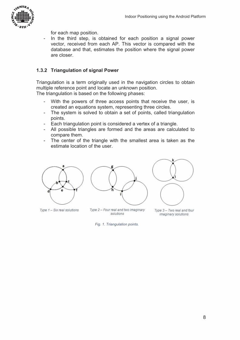
1.3.2 Triangulation of signal Power Triangulation is a term originally used in the navigation circles to obtain multiple reference point and locate an unknown position. The triangulation is based on the following phases:
- With the powers of three access points that receive the user, is created an equations system, representing three circles.
- The system is solved to obtain a set of points, called triangulation points.
- Each triangulation point is considered a vertex of a triangle. - All possible triangles are formed and the areas are calculated to
compare them. - The center of the triangle with the smallest area is taken as the
estimate location of the user.
Fig. 1. Triangulation points.
Indoor Positioning using the Android Platform
9
1.3.3 Heuristics Heuristic methods may be used by themselves or as improvement to two other methods, discarding positions of the database to reduce the span of possible locations.
1.3.3.1 Proximity Heuristics This method is based on the nearest AP to the terminal to determine its position. Depending on to the power received for the user from each AP, the minimum power values are discarded and it is said that the greater power signal received corresponds to the nearest AP. To use this method, the client must be in the position of this access point (the nearest AP).
1.3.3.2 K-nearest neighbors The method of the k-nearest neighbors is part of a family of learning techniques known as learning-by-example (instance-based learning). Learning in these algorithms consist simply on memorize the training examples presented. When a new position is presented to the learning system, a set of similar examples is retrieved from the memory for classify the new position. Therefore, an approximate location of user can be calculated. The drawback of this technique is that it requires a large number of learning points in order to make good estimations.
1.3.3.3 Heuristic Motion
The movement is an important part of the context of a user in a positioning system. It is possible to classify a user as stationary or moving based on the strength of the Wi-Fi signal. Taking into account that the signal strength of the AP's create more power peaks around the estimated position when the device is in motion. The device has to be trained when moving around an area as well as when it is stationary at certain point.
1.3.3.4 Bayes theory Is a probabilistic technique that creates a probability distribution of all the possible positions. Probabilistic techniques achieve a higher precision than deterministic techniques in exchange of bigger computational cost. The Bayesian approach is typically applied in cases where the representation of the environment is in the form of grids. Another alternative for pattern the environment is to use a topological map. In this case the location is based on the fact that the device, identifies automatically that has reached a map node, based on some geometric information of the environment.
Indoor Positioning using the Android Platform
10
1.3.3.5 Neural Networks This technology can build systems capable to learn, adapt to varying conditions, even if it has a sufficient collection of data to predict the future state of some models. Training in this case is used to accelerate learning. It makes memorizing characteristics of the points of interest and thus the device recognizes the location area in real-time.
1.3.4 Conclusions of the main methods for position calculation In the power vector method, the training phase is what makes this method, the most accurate. The technique of triangulation Power, has no training phase of the devices, this method goes directly from the phase of AP's knowledge to the phase of estimate the user position. Heuristic techniques are used to improve accuracy in systems using methods such as triangulation of power, in which the precision can be increased applying heuristic techniques.
Indoor Positioning using the Android Platform
11
1.4 Fingerprinting
The Fingerprinting location model is based on the power of the received signal of the different access points on a certain position, and can then use those values in a series of algorithms that allows it to calculate the user's position. It is called Fingerprinting, because the main part of the method is to create a knowledge base with the power data taken in different environments where the system will be used. A matrix is created with the received power of each access point in a series of known locations.
1.4.1 Location Process - The first step is the Fingerprinting process. In order to do this, it is necessary to examine the network infrastructure of the building, and accumulating the power of the received signal of each access point. This system has better precision when using a high density of training points. The precision of this algorithm depends on the distance between the points that have been measured in the training process. The training process needs to be done once and the data can then be used by all client. It would be necessary to repeat it, in case there were structural changes in the building, or when there are major modifications in the wireless network infrastructure, for instance, if the access point locations change. -With the Fingerprinting knowledge-base created, the first time the client starts, the training data will be downloaded to their android device. -Next, the client would scan the network, getting the signal power from the Aps available in that particular location. -After this processing and, using the "k-nearest neighbors algorithm”, it is possible to compare the data obtained by the client with the knowledge base obtained in the Fingerprinting process to estimate the position where the client is located.
1.5 K-nearest neighbor’s algorithm.
The location model using Fingerprinting is based on finding the power of received signal for each access point in a certain location. Those powers will be treated as the metric distance, and the k-nearest neighbour’s algorithm will be applied. This algorithm searches the database, created in the Fingerprinting process, and selects the points which fits the best compared to the currently received power signals. To select the best fitting points, the smallest Euclidean distance of powers is used, using the powers as metric distances.
Indoor Positioning using the Android Platform
12
Selecting the k (where k means the number of points) points with the smallest distance to the point where the user is, the barycentre is calculated, and this result is the estimated location of the user. The calculation of the distance between the fingerprinting data base points and the user instant point is done as follows:
Current_signal_power = power vector obtained by scanning the Access points signal power on a certain position.
FP_data = database obtained during the fingerprinting process. FP_points = power vector with the obtained results in each point. K-minimums = vector with the three nearest points.
Where:
d(p, pi) = distance(Current_signal_power, FP_points) M = number of points in the fingerprinting database. RSSI_1 would be the power received by the AP1 in a certain point (X, Y). User_location = barycentre (k-minimums)
*RSSI = received signal strength indication. Where barycentre of the k-minimums is:
Being P= user location.
Where X1 would be the first point in the k-minimums vector. As a clarification, if the point where the calculation of the distance is being done does not contain any value of power for one or more of the access points that have been located in our fingerprinting database, a maximum distance will be returned, so when choosing the minimums, that distance will be large, thus ignored, because that point can lead to bad estimations. Moreover, it has to be clarified that, during the fingerprinting process, when taking power values in one point, several measurements were taken in the same point, and then averaged, before storing the result in the fingerprinting database. This makes the algorithm more efficient.
Indoor Positioning using the Android Platform
13
This algorithm is simple enough for being efficient on any machine. For instance, in a laptop to 1.4 GHz, the algorithm is executed in between 1 and 3 milliseconds, depend on numbers of access points detected. In the particular case of this application, using a standard android device with two cores of 1,2Ghz, the algorithm is executed in between 1 and 2 seconds.
1.6 Measurement.
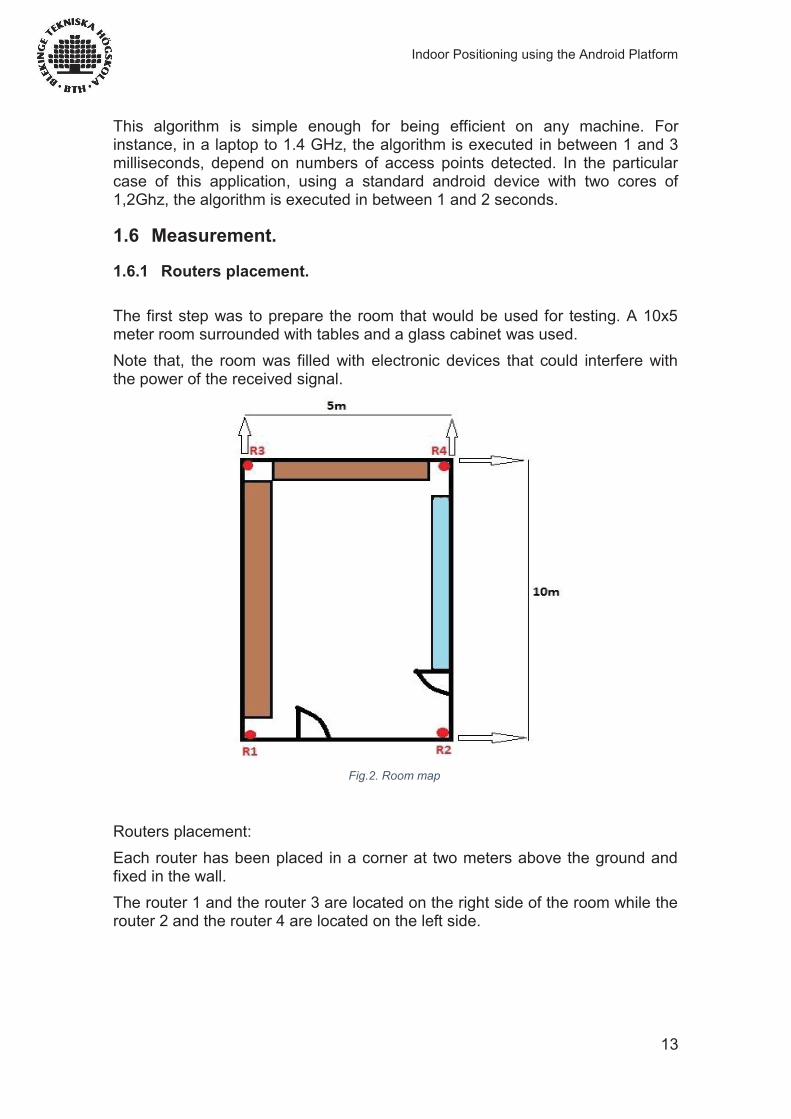
1.6.1 Routers placement. The first step was to prepare the room that would be used for testing. A 10x5 meter room surrounded with tables and a glass cabinet was used. Note that, the room was filled with electronic devices that could interfere with the power of the received signal.
Fig.2. Room map
Routers placement: Each router has been placed in a corner at two meters above the ground and fixed in the wall. The router 1 and the router 3 are located on the right side of the room while the router 2 and the router 4 are located on the left side.
Indoor Positioning using the Android Platform
14
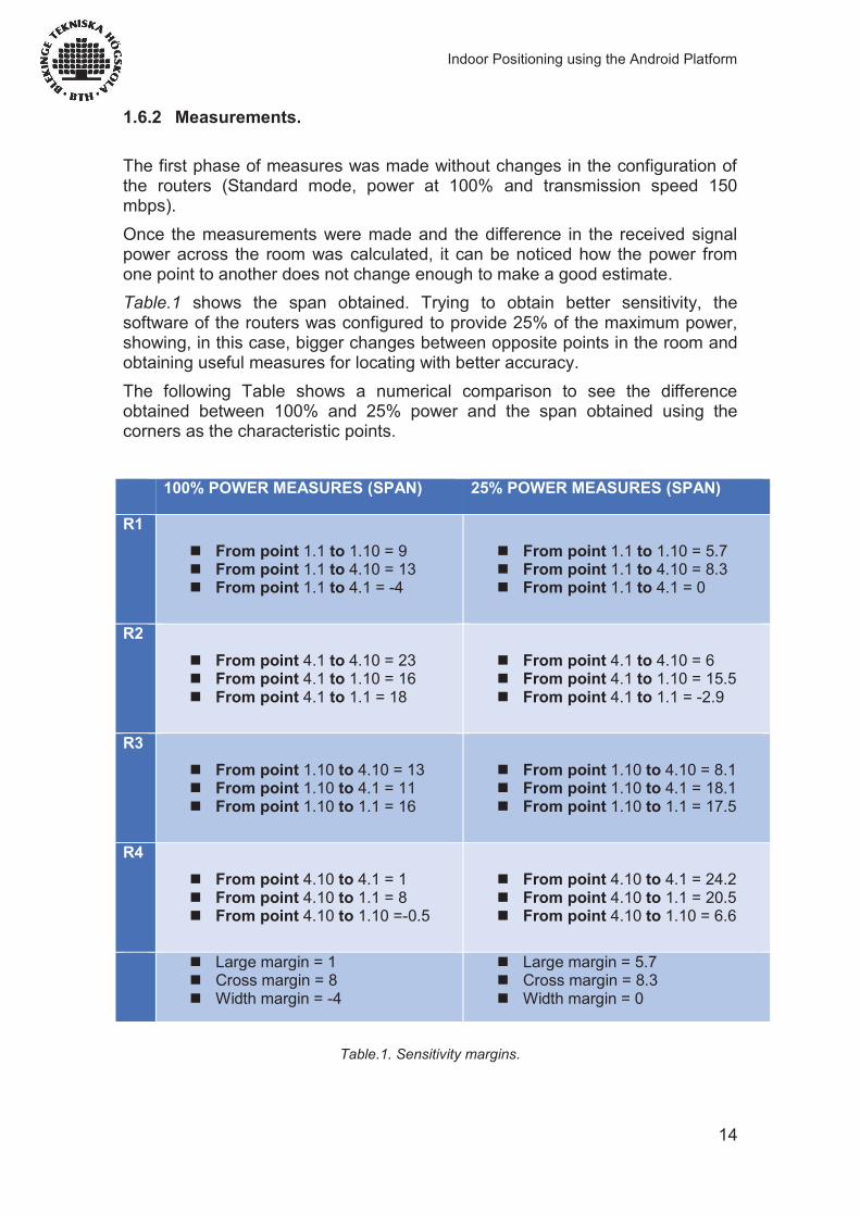
1.6.2 Measurements. The first phase of measures was made without changes in the configuration of the routers (Standard mode, power at 100% and transmission speed 150 mbps). Once the measurements were made and the difference in the received signal power across the room was calculated, it can be noticed how the power from one point to another does not change enough to make a good estimate. Table.1 shows the span obtained. Trying to obtain better sensitivity, the software of the routers was configured to provide 25% of the maximum power, showing, in this case, bigger changes between opposite points in the room and obtaining useful measures for locating with better accuracy. The following Table shows a numerical comparison to see the difference obtained between 100% and 25% power and the span obtained using the corners as the characteristic points. 100% POWER MEASURES (SPAN) 25% POWER MEASURES (SPAN)
R1
From point 1.1 to 1.10 = 9 From point 1.1 to 4.10 = 13 From point 1.1 to 4.1 = -4
From point 1.1 to 1.10 = 5.7 From point 1.1 to 4.10 = 8.3 From point 1.1 to 4.1 = 0
R2 From point 4.1 to 4.10 = 23 From point 4.1 to 1.10 = 16 From point 4.1 to 1.1 = 18
From point 4.1 to 4.10 = 6 From point 4.1 to 1.10 = 15.5 From point 4.1 to 1.1 = -2.9
R3 From point 1.10 to 4.10 = 13 From point 1.10 to 4.1 = 11 From point 1.10 to 1.1 = 16
From point 1.10 to 4.10 = 8.1 From point 1.10 to 4.1 = 18.1 From point 1.10 to 1.1 = 17.5
R4 From point 4.10 to 4.1 = 1 From point 4.10 to 1.1 = 8 From point 4.10 to 1.10 =-0.5
From point 4.10 to 4.1 = 24.2 From point 4.10 to 1.1 = 20.5 From point 4.10 to 1.10 = 6.6
Large margin = 1 Cross margin = 8 Width margin = -4
Large margin = 5.7 Cross margin = 8.3 Width margin = 0
Table.1. Sensitivity margins.
Indoor Positioning using the Android Platform
15
It can be noticed that with the standard configuration of routers, emitting 100% of their power, the span obtained is not useful to locate the user neither in lengthwise nor in widthwise of the room. Taken the minimum span calculated of the routers lengthwise the room, looking at R4 (router 4) in the measurements obtained from the points 4.1 to 4.10, it shows a difference of one unit of signal power; one single unit of unit difference between two points with 10 meters separating them. On the other hand, the measurements obtained when the router is configured to emit 25% of power are better. Although the span is still being quite small, it is good enough to know in which quadrant the user is located.
1.7 Simulation using MATLAB.
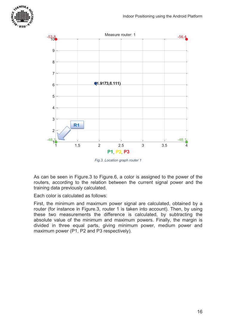
1.7.1 Location. Once these spans are calculated and having decided to use routers using 25 % of emission power for the application, the next step is the simulation of our application. MATLAB was used to simulate the behavior of the application in a quick and relatively simple way, it was an ideal tool for this type of simulations. Figure.3 shows the estimation point where the user is located and the power of router 1 in each corner of the room. The following three graphs show the behavior of the other three routers. It is possible to get the estimated point by implementing the algorithm K-nearest neighbors (mentioned in section (1.5) of this report), adapted to our particular case and using the database obtained from the routers in the training phase.
Indoor Positioning using the Android Platform
16
Fig.3. Location graph router 1
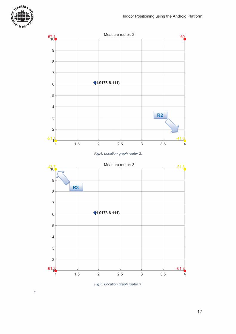
As can be seen in Figure.3 to Figure.6, a color is assigned to the power of the routers, according to the relation between the current signal power and the training data previously calculated. Each color is calculated as follows: First, the minimum and maximum power signal are calculated, obtained by a router (for instance in Figure.3, router 1 is taken into account). Then, by using these two measurements the difference is calculated, by subtracting the absolute value of the minimum and maximum powers. Finally, the margin is divided in three equal parts, giving minimum power, medium power and maximum power (P1, P2 and P3 respectively).
1 1.5 2 2.5 3 3.5 41
2
3
4
5
6
7
8
9
10
-48.1
(1.9173,6.111)
-53.8
(1.9173,6.111)
-48.1
(1.9173,6.111)
-56.4
(1.9173,6.111)
Measure router: 1
R1
Indoor Positioning using the Android Platform
17
Fig.4. Location graph router 2.
Fig.5. Location graph router 3.
1
1 1.5 2 2.5 3 3.5 41
2
3
4
5
6
7
8
9
10
-51.1
(1.9173,6.111)
-57.1
(1.9173,6.111)
-41.6
(1.9173,6.111)
-60
(1.9173,6.111)
Measure router: 2
1 1.5 2 2.5 3 3.5 41
2
3
4
5
6
7
8
9
10
-61.2
(1.9173,6.111)
-43.7
(1.9173,6.111)
-61.8
(1.9173,6.111)
-51.8
(1.9173,6.111)
Measure router: 3
R2
R3
Indoor Positioning using the Android Platform
18
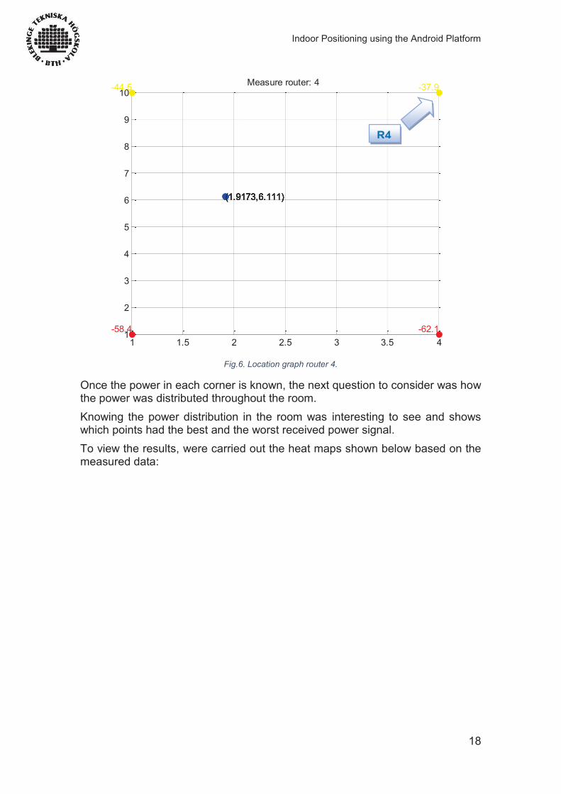
Fig.6. Location graph router 4.
Once the power in each corner is known, the next question to consider was how the power was distributed throughout the room. Knowing the power distribution in the room was interesting to see and shows which points had the best and the worst received power signal. To view the results, were carried out the heat maps shown below based on the measured data:
1 1.5 2 2.5 3 3.5 41
2
3
4
5
6
7
8
9
10
-58.4
(1.9173,6.111)
-44.5
(1.9173,6.111)
-62.1
(1.9173,6.111)
-37.9
(1.9173,6.111)
Measure router: 4
R4
Indoor Positioning using the Android Platform
19
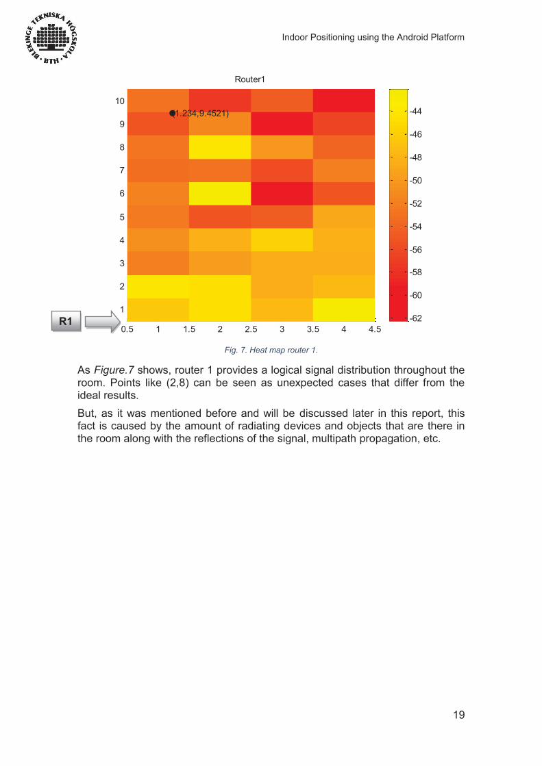
Fig. 7. Heat map router 1.
As Figure.7 shows, router 1 provides a logical signal distribution throughout the room. Points like (2,8) can be seen as unexpected cases that differ from the ideal results. But, as it was mentioned before and will be discussed later in this report, this fact is caused by the amount of radiating devices and objects that are there in the room along with the reflections of the signal, multipath propagation, etc.
0.5 1 1.5 2 2.5 3 3.5 4 4.5
1
2
3
4
5
6
7
8
9
10
Router1
(1.234,9.4521)
-62
-60
-58
-56
-54
-52
-50
-48
-46
-44
R1
Indoor Positioning using the Android Platform
20
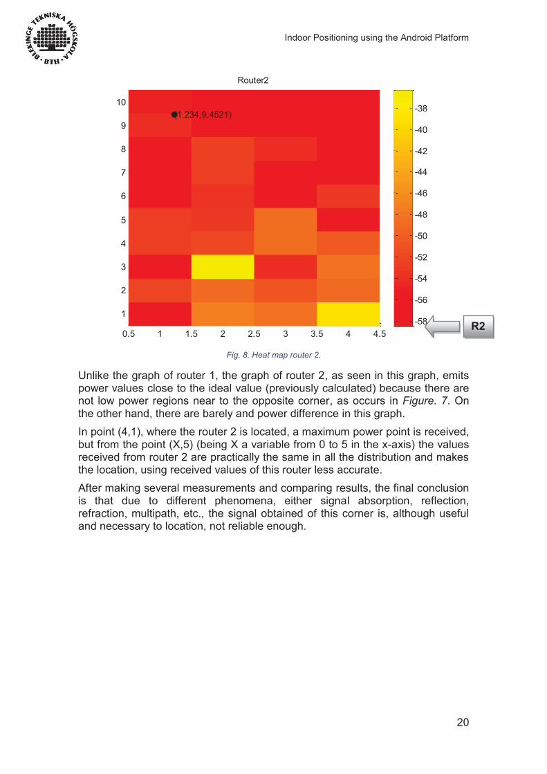
Fig. 8. Heat map router 2.
Unlike the graph of router 1, the graph of router 2, as seen in this graph, emits power values close to the ideal value (previously calculated) because there are not low power regions near to the opposite corner, as occurs in Figure. 7. On the other hand, there are barely and power difference in this graph. In point (4,1), where the router 2 is located, a maximum power point is received, but from the point (X,5) (being X a variable from 0 to 5 in the x-axis) the values received from router 2 are practically the same in all the distribution and makes the location, using received values of this router less accurate. After making several measurements and comparing results, the final conclusion is that due to different phenomena, either signal absorption, reflection, refraction, multipath, etc., the signal obtained of this corner is, although useful and necessary to location, not reliable enough.
0.5 1 1.5 2 2.5 3 3.5 4 4.5
1
2
3
4
5
6
7
8
9
10
Router2
(1.234,9.4521)
-58
-56
-54
-52
-50
-48
-46
-44
-42
-40
-38
R2
Indoor Positioning using the Android Platform
21
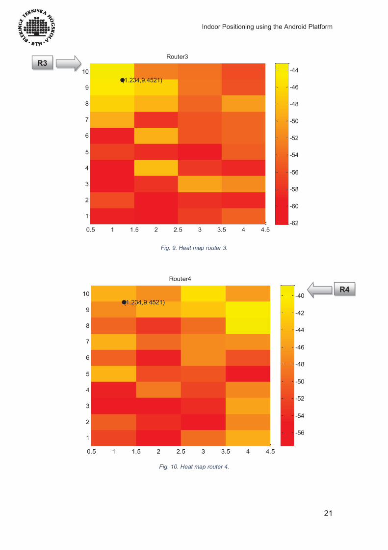
Fig. 9. Heat map router 3.
Fig. 10. Heat map router 4.
0.5 1 1.5 2 2.5 3 3.5 4 4.5
1
2
3
4
5
6
7
8
9
10
Router3
(1.234,9.4521)
-62
-60
-58
-56
-54
-52
-50
-48
-46
-44
0.5 1 1.5 2 2.5 3 3.5 4 4.5
1
2
3
4
5
6
7
8
9
10
Router4
(1.234,9.4521)
-56
-54
-52
-50
-48
-46
-44
-42
-40
R3
R4
Indoor Positioning using the Android Platform
22
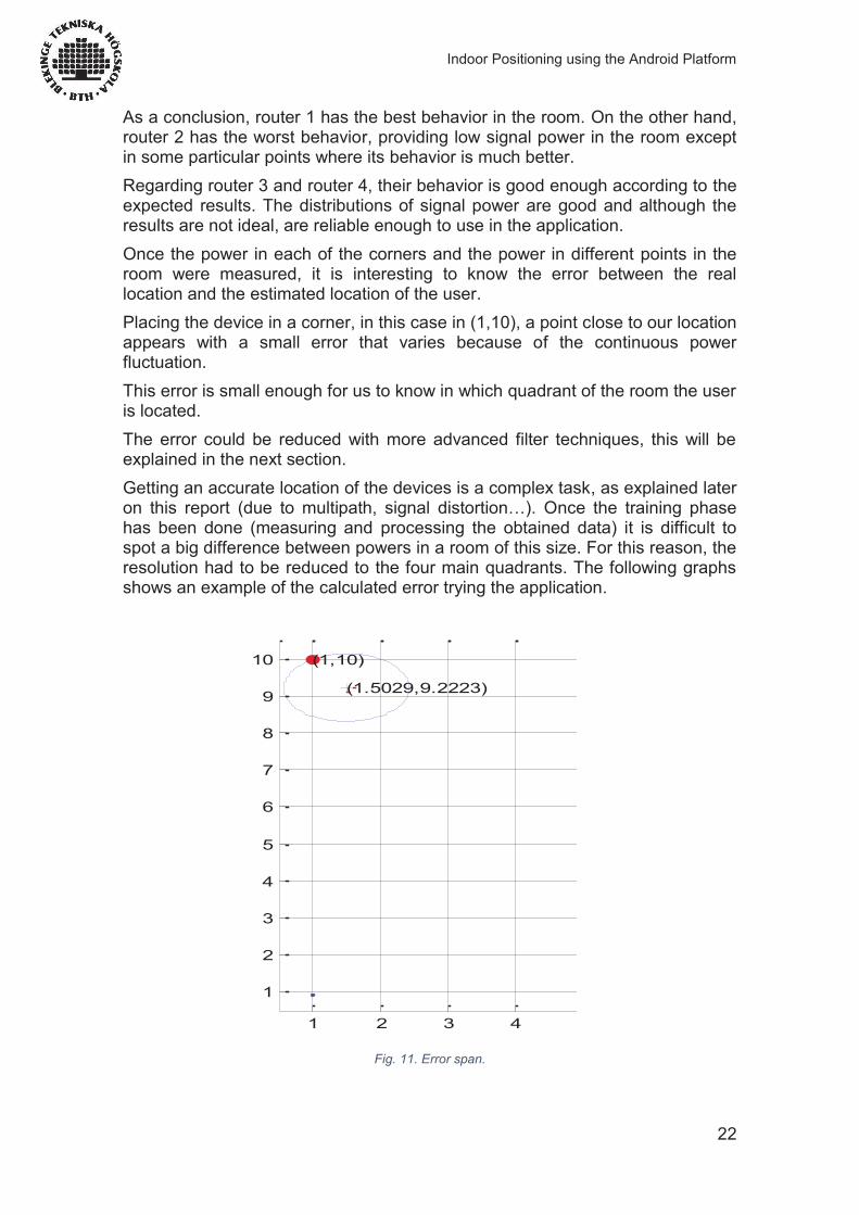
As a conclusion, router 1 has the best behavior in the room. On the other hand, router 2 has the worst behavior, providing low signal power in the room except in some particular points where its behavior is much better. Regarding router 3 and router 4, their behavior is good enough according to the expected results. The distributions of signal power are good and although the results are not ideal, are reliable enough to use in the application. Once the power in each of the corners and the power in different points in the room were measured, it is interesting to know the error between the real location and the estimated location of the user. Placing the device in a corner, in this case in (1,10), a point close to our location appears with a small error that varies because of the continuous power fluctuation. This error is small enough for us to know in which quadrant of the room the user is located. The error could be reduced with more advanced filter techniques, this will be explained in the next section. Getting an accurate location of the devices is a complex task, as explained later on this report (due to multipath, signal distortion…). Once the training phase has been done (measuring and processing the obtained data) it is difficult to spot a big difference between powers in a room of this size. For this reason, the resolution had to be reduced to the four main quadrants. The following graphs shows an example of the calculated error trying the application.
1 2 3 4
1
2
3
4
5
6
7
8
9
10 (1,10)
(1.5029,9.2223)
Fig. 11. Error span.
Indoor Positioning using the Android Platform
23
1.8 Radio Frequency Behaviors
According to [4] David D. Coleman & David A. Wescott, (2009). As an RF signal travels through the air and other mediums, it can move and behave in different ways. RF propagation behaviors include absorption, reflection, scattering, refraction, diffraction, free space path loss, multipath, attenuation, and gain.
1.8.1 Wave Propagation
When we use the term propagate, we try to envision an RF signal broadening or spreading as it travels farther away from the antenna. An excellent analogy is an earthquake. Note the concentric seismic rings that propagate away from the epicentre of the earthquake. RF waves behave in much the same fashion. The manner in which a wireless signal moves is often referred to as propagation behaviour. With the study of waves propagating, you can be sure that access points are deployed in the proper location and that the proper type of antenna is chosen.
1.8.2 Absorption
The most common RF behaviour is absorption. If a signal does not bounce off an object, move around an object, or pass through an object, then 100 percent absorption has occurred. Most materials will absorb some amount of an RF signal to varying degrees. Absorption can be a leading cause of attenuation. Even objects with large water content such as paper, cardboard, fish tanks, and so forth, can absorb signals.
1.8.3 Reflection
When a wave hits a smooth object that is larger than the wave itself, depending on the media, the wave may bounce in another direction. This behaviour is categorized as reflection.
In an indoor environment, microwaves reflect off smooth surfaces such as doors, walls, and file cabinets. Anything made of metal will absolutely cause reflection. Other materials such as glass and concrete may cause reflection as well.
1.8.4 Scattering
This is another example of an RF propagation behaviour called scattering, (sometimes called scatter).
Scattering can easily be described as multiple reflections. These multiple reflections occur when the electromagnetic signal's wavelength is larger than pieces of whatever medium the signal is passing through.
Indoor Positioning using the Android Platform
24
1.8.5 Refraction
In addition to RF signals being absorbed or bounced (via reflection or scattering), if certain conditions exist, an RF signal can actually be bent in a behaviour known as refraction. A straightforward definition of refraction is the bending of an RF signal as it passes through a medium with a different density, thus causing the direction of the wave to change. RF refraction most commonly occurs as a result of atmospheric conditions.
1.8.6 Diffraction
Not to be confused with refraction, another RF propagation behaviour exists that also bends the RF signal; it is called diffraction. Diffraction is the bending of an RF signal around an object (whereas refraction, is the bending of a signal as it passes through a medium). Diffraction is the bending and the spreading of an RF signal when it encounters an obstruction. The conditions that must be met for diffraction to occur depend entirely on the shape, size, and material of the obstructing object as well as the exact characteristics of the RF signal, such as polarization, phase, and amplitude.
1.8.7 Loss (Attenuation)
Loss, also known as attenuation, is best described as the decrease in amplitude, or signal strength. A signal may lose strength while on a wire or in the air. On the wired portion of the communications (RF cable), the AC electrical signal will lose strength because of the electrical impedance of coaxial cabling and other components such as connectors. After the RF signal is radiated into the air via the antenna, the signal will attenuate due to absorption, distance, and the negative effects of multipath.
1.8.8 Multipath
Multipath is a propagation phenomenon that results in two or more paths of a signal arriving at a receiving antenna at the same time or typically within nanoseconds of each other. A signal may reflect off an object or scatter, refract, or diffract. These propagation behaviours can all result in multiple paths of the same signal.
In an indoor environment, reflected signals can be caused by long hallways, walls, desks, floors, file cabinets, and numerous other obstructions. The propagation behaviour of reflection is typically the main cause of high-multipath environments.
1.9 Filters.
At this point, the problem of estimating of the position is analyzed. For this problem it is necessary to define a model that incorporates mobile movement restriction which positions are more feasible given the position in the previous instant.
Indoor Positioning using the Android Platform
25
According to [6] Claudia Avallone & Germán Capdehourat, (2011), to solve the problem with the fluctuation of the signal, and be sure that the user tracking is correct and with a good precision, some kind of filter can be used:
1.9.1 Bayesian filter. This method corresponds to the extension of the maximum probability estimate view for the static case, but now adding the information from the past trajectory. In this case the movement of the mobile phone is defined using the most probable point.
1.9.2 Kalman Filter. The Kalman filter corresponds to a particular case of Bayesian filter, which considered a linear model and Gaussian white noise of zero average. Given a model of this form, the kalman filter is a recursive estimator considering the "average square error" as error measure.
1.9.3 Kalman Filter tracks. According to [12] Simo ALI-LOYTTY, Tommi PERALA, Ville HONKAVIRTA, and Robert PICH ́ E, (2009).The Kalman filter tracks or FKF (Fingerprint Kalman Filter) is a filter of the same family as extensions to the Kalman filter and EKF (Extended Kalman Filter) and UKF (Unscented Kalman Filter). The latter can also be applied to the problem of tracking because they are extensions of filter Kalman nonlinear models. In each iteration these filters approximate the conditional expectation based on the previous state and error estimate and calculates the estimate of the new state and the corresponding error.
1.9.4 Particle filter. The particle filter is a sequential Monte Carlo method that generates random samples (particles) according to some movement model and estimated their probability densities from the tracks. Unlike the Kalman filter allows to work with non-linear models and non-Gaussian noise. This approach also allows to incorporate the building map information to improve the estimation by removing the particles that make impossible movements like walking through walls. The main disadvantage of these methods is the high computational cost, an important use for real-time applications with low power mobile limiting.
Indoor Positioning using the Android Platform
26
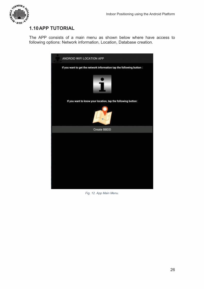
1.10 APP TUTORIAL
The APP consists of a main menu as shown below where have access to following options: Network information, Location, Database creation.
Fig. 12. App Main Menu.
Indoor Positioning using the Android Platform
27
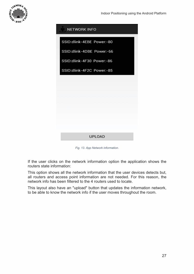
Fig. 13. App Network information.
If the user clicks on the network information option the application shows the routers state information: This option shows all the network information that the user devices detects but, all routers and access point information are not needed. For this reason, the network info has been filtered to the 4 routers used to locate. This layout also have an "upload" button that updates the information network, to be able to know the network info if the user moves throughout the room.
Indoor Positioning using the Android Platform
28
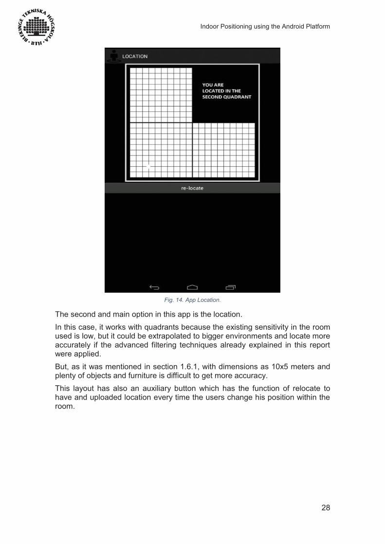
Fig. 14. App Location.
The second and main option in this app is the location. In this case, it works with quadrants because the existing sensitivity in the room used is low, but it could be extrapolated to bigger environments and locate more accurately if the advanced filtering techniques already explained in this report were applied. But, as it was mentioned in section 1.6.1, with dimensions as 10x5 meters and plenty of objects and furniture is difficult to get more accuracy. This layout has also an auxiliary button which has the function of relocate to have and uploaded location every time the users change his position within the room.
Indoor Positioning using the Android Platform
29
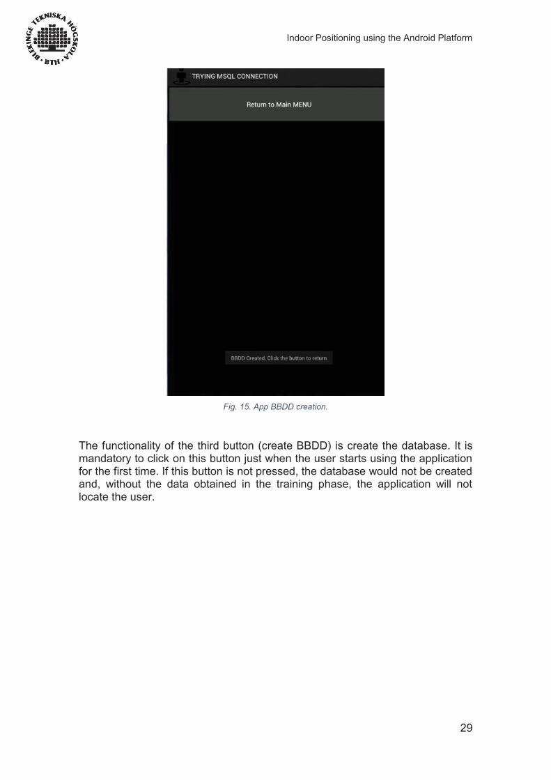
Fig. 15. App BBDD creation.
The functionality of the third button (create BBDD) is create the database. It is mandatory to click on this button just when the user starts using the application for the first time. If this button is not pressed, the database would not be created and, without the data obtained in the training phase, the application will not locate the user.
Indoor Positioning using the Android Platform
30
1.11 WIFI Android API.
According to [10] Jhonas M. (2012), Android allows applications to view the access the state of the wireless connections at very low level. The application can access to all the information of a Wi-Fi connection.
With this API, Android provides information such as connected network's link speed, IP address, negotiation state and so on. Applications can also scan, add, save, terminate and initiate Wi-Fi connections.
Android provides the WifiManager API to manage all aspects of Wi-Fi connectivity. We can instantiate this class by calling getSystemService method. Its syntax is given below:
WifiManager mainWifiObj; mainWifiObj = (WifiManager) getSystemService(Context.WIFI_SERVICE);
In order to scan a list of wireless networks, you also need to register your BroadcastReceiver. It can be registered using registerReceiver method with argument of your receiver class object. Its syntax is given below:
class WifiScanReceiver extends BroadcastReceiver { public void onReceive(Context c, Intent intent) { } } WifiScanReceiver wifiReciever = new WifiScanReceiver(); registerReceiver(wifiReciever, new IntentFilter(WifiManager.SCAN_RESULTS_AVAILABLE_ACTION));
The Wi-Fi scan can be started by calling the startScan method of the WifiManager class. This method returns a list of ScanResult objects. It is possible to access any object by calling the get method of list. Its syntax is given below:
List<ScanResult> wifiScanList = mainWifiObj.getScanResults(); String data = wifiScanList.get(0).toString(); Then, if it is necessary, is possible to obtain the SSID, BSSID, RSSI, etc. of the access points you are analysing. In this project, it has only been needed the SSID and the BSSID of the access points and a simple Java code to filter and take only the useful access points in the network. The fingerprinting database has been created with the information received using this API, so, it can be said that this simple code is the core of the application.
Apart from that, you can have more control over your WIFI by using the methods defined in WifiManager class. They are listed as follows:
Indoor Positioning using the Android Platform
31
Method & Description
addNetwork(WifiConfiguration config) This method add a new network description to the set of configured networks.
createWifiLock(String tag) This method creates a new WifiLock.
disconnect() This method disassociate from the currently active access point.
enableNetwork(int netId, boolean disableOthers) This method allow a previously configured network to be associated with.
getWifiState() This method gets the Wi-Fi enabled state
isWifiEnabled() This method return whether Wi-Fi is enabled or disabled.
setWifiEnabled(boolean enabled) This method enable or disable Wi-Fi.
updateNetwork(WifiConfiguration config) This method update the network description of an existing configured network.
Indoor Positioning using the Android Platform
32
1.12 Conclusions
This application has served as evidence that indoor wireless positioning is possible, allowing improvements of accuracy in the future by using more complex techniques as it has been explained in section 1.9 of this report. Another relevant theme is that if the measurement time in our room increases, that means, for example, if we make a lot of measurements in one spot in a whole day, more data would be available to have higher accuracy. As a result of this, it would be possible to achieve a more accurate location. Moreover, other location techniques such as GPS (in outdoor environments) have had a huge development and now, they operate with great accuracy taking into account the system capabilities. Most of the apps we are used to employ every day work in combination with GPS location (e.g. Facebook, Google Maps, Twitter, augmented reality apps) but regrettably, indoor locations have not been explored exhaustively yet. By developing this project, we have been able to notice that with time and research, this kind of locations may be very useful for security, hospitals, military use and so on. In the near future it might become more accurate than GPS and easier to implement because the Wi-Fi networks are nowadays, present in most of the buildings and houses of the world. It has been a great experience trying to develop a newfangled technology and we have learnt a lot of concepts about this kind of locations that in the short term will take much more importance.
This project has uncovered another functional feature of mobile phones: it could be used for instance to locate people with Alzheimer and let them live their life as freely as possible but, at the same time having a continuous control over them. Therefore, as we have been discussing, this opens up many new possibilities for the user applications and industry
The use of Android as a platform has been successful, the combination of an accessible and well documented API along with system deployed on numerous mobile phones let us foresee that in the near future both the number of applications and the need for developers in this area will increase. Hence the experience gained during the development of this project will be highly valued.
Indoor Positioning using the Android Platform
33
1.13 Bibliography
1.13.1 Books by a single author: [1] W. Frank abelson, (). Android guia para desarrolladores. 2nd ed.: Anaya multimedia. [2] Weej Meng Lee, (). Android Desarrollo de aplicaciones ganadoras . 1st ed.: Anaya multimedia. [3] Grant Allen, (). Beginning Android. 4th ed.: Apress.
1.13.2 Books by two authors: [4] David D. Coleman & David A. Wescott, (2009). 'Radio Frequency Fundamentals'. In: (ed), Certified Wireless Network Administrator Offcial Study Guide. 1st ed. England: Sybex. pp.765. [5] Satya Komatineni, Dave MacLean, (e.g. 1954). Pro Android. 4th ed. e.g. England: Apress [6] Claudia Avallone & Germán Capdehourat, (2011). Posicionamiento indoor con señales Wi-Fi. Tratamiento estadístico de señales. 3, pp.18
1.13.3 Website articles: [7] Salvador Gómez Oliver (2011). Curso Programación Android. [ONLINE] Available at: http://www.slideshare.net/dcastacun/manual-programacin-android. [8] Lars Vogel (2012). Android Location API. [ONLINE] Available at: http://www.vogella.com/tutorials/AndroidLocationAPI/article.html. [9] Rico (2013). Wifi Location on Android devices. [ONLINE] Available at: http://stackoverflow.com/questions/21169427/wifi-location-not-available-on-android. [10] Jhonas M. (2012). Android Wifi API tutorial. [ONLINE] Available at: http://www.tutorialspoint.com/android/android_wi_fi.htm. [11] (2014). Android.net.wifi. [ONLINE] Available at: http://developer.android.com/reference/android/net/wifi/package-summary.html. [12] Simo ALI-LOYTTY, Tommi PERALA, Ville HONKAVIRTA, and Robert PICH ́ E, (2009). Fingerprint Kalman Filter in Indoor Positioning Applications. Tampere University of Technology, Finland. (), pp.6
1.13.4 Website multimedia tutorials: [13] Jesús Tomás (2011). Uso de base de datos en Android. [ONLINE] Available at: https://media.upv.es/player/?autoplay=true&id=0303837d-2982-5948-b34b-c3704df15cff. [14] Alonso (2013). Creación de una base de datos SQLite en Android. [ONLINE] Available at: https://www.youtube.com/watch?v=ma8z1rcFyjI.