indubox gsm ix v2.0b e - bausch datacom gsm ix v2.0b_e.pdf · 1. introduction this manual is the...
TRANSCRIPT

Installation & Configuration manual
InduBox GSM IX

InduBox GSM IX Manual with Socket Server Open AT® application Version 2.0b 2/34
! CAUTION !
ELECTRIC SHOCK HAZARD IF COVER REMOVED
SERVICE BY QUALIFIED PERSONEL ONLY
Document History
Date Version Auteur
14/06/12 V1.0 Preliminary Filip Lavaerts Creation / V1.0 InduBox GSM IX hardware
17/07/12 V1.1 D. Truyers Addition of 'Important AT Commands' + 'Socket Serv'application in Open AT®
24/08/12 V1.1a Filip Lavaerts Additional JP6 & 7
14/11/12 V1.1b D. Truyers Power supply consumption change
29/03/13 V2.0a/b Filip Lavaerts JP6 (RS485/pin1) indication text error
InduBox GSM IX Manual with Socket Server Open AT® application Version 2.0b 3/34

Table of Contents
1. Introduction 6
2. Block Diagram 7
3. Specifications 9 3.1 Housing and Connectors3.2 Environmental conditions3.3 Power Supply Specifications3.4 GSM Module Specifications
4. SIM Card 10
5. Ports and Connectors 125.1Mains Power Connection5.2Non isolated DTE interface 135.3 Isolated DTE Interfaces 14
5.3.1. Isolated RS-232 connection5.3.2. Isolated RS-485 connection 16
5.4Antenna Interface 17
6. LED Indicators 18
7. Jumper Settings 19
8. Watchdog Functionality 208.1 Periodical reset8.2 External reset
9. AT Command Interface 21 9.1Most important AT commands
10. ‘Socket Server’ application in Open AT® 2310.1 Introduction10.2 General Description10.3 Basic Setup 2410.4 Possible Modes
10.4.1 CSD mode10.4.2 GPRS mode10.4.3 SCKServ mode 25
10.5 How To Switch Between The 3 Modes via SMS 10.5.1 Switch to GPRS mode10.5.2 Switch to SCKserv mode 2610.5.3 Switch to CSD mode
10.6 How to switch between the 3 Modes via “at” commands10.7 DOTA upgrade (optional) 27
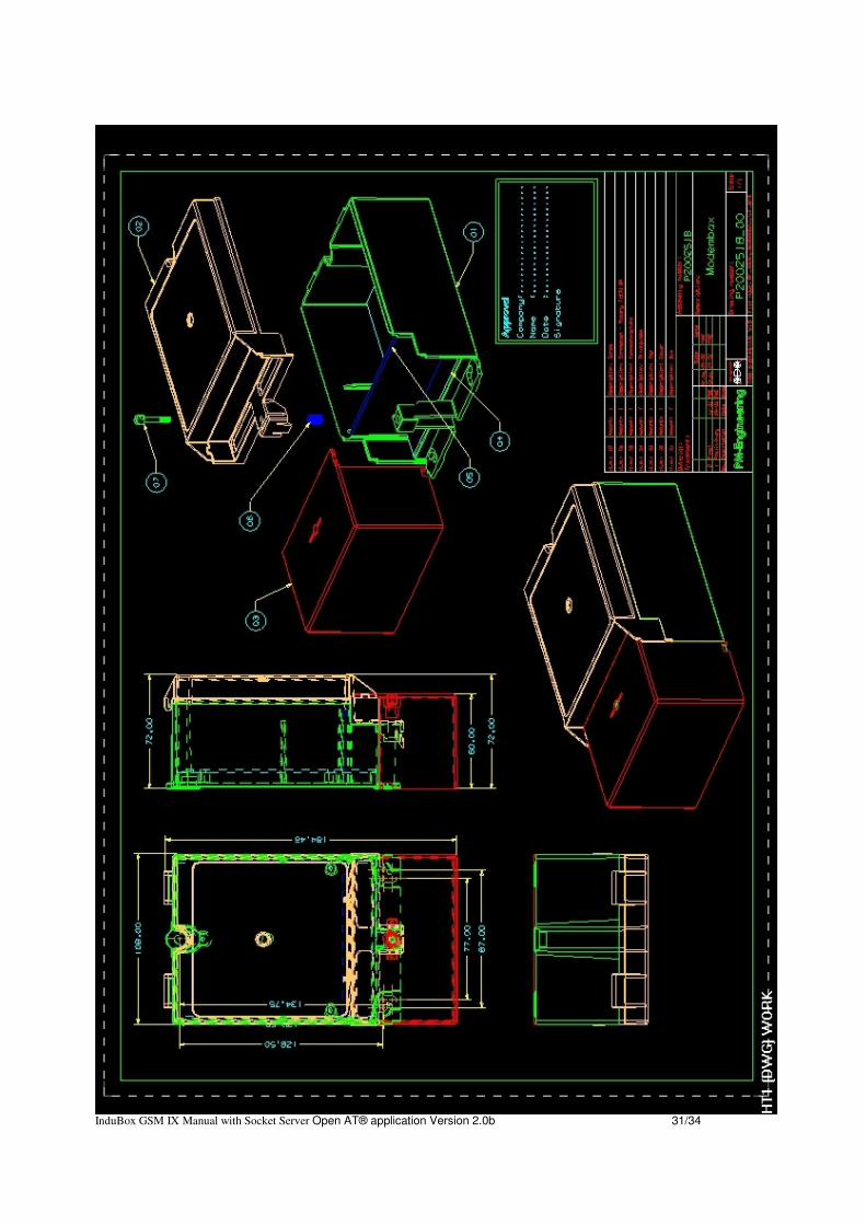
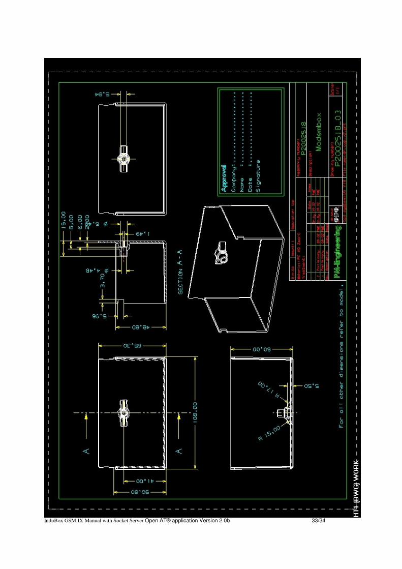
A. EC-declaration of conformity 29B. Basic Dimensions 31InduBox GSM IX Manual with Socket Server Open AT® application Version 2.0b 4/34

Serial flow as used in this manual :
InduBox GSM IX Manual with Socket Server Open AT® application Version 2.0b 5/34
DCEDTE
TxDRxDDTR
DCD
RTSCTSRI
DSR
GND
Modem
InduBox GSM IX
Communication
device
PC
POS
PLC
Application
IN
OUT
Data
Terminal
Equipment
Data
Communication
Equipment

1. Introduction
This manual is the reference when setting up the InduBox GSM IX modem for yourapplication. Because of the nature of this product and it's field of application, somedegree of technical background knowledge regarding the application and data-communication is assumed.
The InduBox GSM IX modem is a versatile communication device designed to providea very flexible data communication solution for an industrial environment. The InduBoxGSM IX modem contains a number of options to accommodate different communicationspeeds, power supplies and interfaces.
The InduBox GSM IX is designed to transmit and receive –transparent- ASCII formatteddata on a GSM data channel. Communication between the InduBox GSM IX and a DTErange from 300 to 115.200 bps. With the GPRS/UMTS option and embedded TCP/IPstack, data can be send/received into a TCP/UDP socket to and from a remote socketserver.
Besides serial communication using standard RS-232, other galvanically and logicallyseparated interfaces are available like RS-232 3-wire and RS-485 3-wire.
Besides a periodical (hard) reset, configurable between 1 and 168 hour, an externalmodem reset is possible via the additional 'V+'-connection to ensure a proper modemworking.
The InduBox GSM IX is designed in a robust housing with different power supplyoptions accepting a wide range of AC voltages.
InduBox GSM IX Manual with Socket Server Open AT® application Version 2.0b 6/34

2. Block Diagram
The block diagram below details the location and interconnection of the differentfunctional units within the modem. The most important units are briefly described.
AC/DC power supply The mains supply (ac) must be connected to the InduBox GSM IX modem via a 2 pinterminal block with screw contacts. Make sure the voltage supplied to the modem is inthe range of the InduBox GSM IX input voltage (see specifications for details onvoltage range).
Long Term Watchdog A long term watchdog circuit is implemented. The modem will perform a reset each 1 to168 hour (configurable) and/or if necessary via the external '+V'-connection to preventa lock-up. The power supply of the GSM/GPRS module will be disconnected for a fewseconds after the reset period. A ‘heartbeat’-LED is implemented to check the long termwatchdog.
InduBox GSM IX Manual with Socket Server Open AT® application Version 2.0b 7/34

Switched regulator To create the necessary dc-voltage (Vgsm) to power the GSM/GPRS module a 2A stepdown switching regulator is implemented.
Configuration InterfaceThe InduBox GSM IX modem has one complete (TxD, RxD, DCD, DTR, RTS, CTS, RIand GND) RS-232 interface. This RS-232 interface is not isolated and must be used toconfigure and/or update the Sierra Wireless (Wavecom) GSM/GPRS module. Thisinterface has a RJ-45 connector.
Isolated DTE interfaces The InduBox GSM IX has 2 galvanically isolated serial interfaces :
3- wire RS-232 (RxD, TxD, GND’) :
This interface is connected (galvanically separated) to the UART1 of the SL6087GSM/GPRS module. V' - pin can be used for external reset (V') or for powering (100 mA Imax) an externaldevice (+5V'), selectable via resistor stuffing.
3- wire RS-485 (A, B, GND’) :
This interface is connected (galvanically separated) to the UART2 of the SL6087GSM/GPRS module.
V' - pin can be used for external reset (V') or for powering (100 mA Imax) an externaldevice (+5V'), selectable via resistor stuffing.
V.24 Status LED’s The V.24 lines to and from the UART1 GSM/GPRS module have a LED indicator.
GSM/GPRS module The InduBox GSM IX has a built-in Sierra Wireless (Wavecom) SL6087 GSM/GPRSQuad band module. Different applications/configurations are possible with or withoutOpenAT firmware.
InduBox GSM IX Manual with Socket Server Open AT® application Version 2.0b 8/34

3. Specifications
3.1 Housing and Connectors
• Housing: Bausch InduBox IP51 housingbottom enclosure and sealable connector cover ABS with self-extinguishing V0 additivetransparent coverpolycarbonate + self-extinguishing V1
dimensions with connector cover: 180 x 108 x 71 mmdimensions without connector cover: 145 x 108 x 71 mm
• Connectors: Mains plug and connector (terminal block screw connector)pitch 5.08 mmmaximum wiring section 2.5 mm2
Female RJ-45 connectors (RS-232, RS-485)
AMP 50 Ohm FME antenna connector
3.2 Environmental conditions
Temperature in use -25°C / + 55°CHumidity in use 10% - 75% (non condensing)
3.3 Power Supply Specifications
Input voltage range: 90 – 253 VacInput frequency: 47 – 63 HzPower: idle 3,5 Widle - 6,4 VA
Max. 4,5 Wmax – 7,5 VA
3.4 GSM-module Specifications
The InduBox GSM IX modem uses a Sierra Wireless (Wavecom) SL6087 quad bandGSM or GSM/GPRS module. The AirPrime SL6087 features 2G quad-band (850/900/1800/1900 MHz) connectivity. Itcan be used as a simple modem controlled via AT commands or it can host a standardANSI C/C++ application and act as a single processor for the customer solution,eliminating the need for an external processor and reducing the total size and cost ofthe final product and all this thanks to a full set of Plug-Ins for Open AT® OS, enablingBausch Datacom to easily add TCP/IP functionalities and Internet security. The modulealso has industrial features like an extended temperature range (-40°C to +85°C ClassB). Check the Sierra Wireless reference manual for detailed information.
InduBox GSM IX Manual with Socket Server Open AT® application Version 2.0b 9/34

4. SIM Card
Disconnect the mains power before opening theInduBox GSM IX modem!
Install a SIM card into the SIM card interface socket. Without a SIM card the InduBoxGSM IX will communicate with the DTE but will not respond properly on all commands.
Most applications are using a SIM card with disabled PIN code request !
The International Mobile Subscriber Identity (IMSI) is used for internal signaling and issaved on the SIM (processor card). If the SIM is removed from the terminal, anyexisting connections are cleared and further call setup is prevented with one exception:emergency calls.
Use the +WIMEI? command to view the IMEI code of the GSM module.InduBox GSM IX Manual with Socket Server Open AT® application Version 2.0b 10/34
Power Supply
GSM/GPRS
module
MAINS
RS-232 ANTRS-485
SIM

How to install the SIM card:
1. Disconnect the mains power and DTE interface.2. Open the InduBox GSM IX enclosure.3. The SIM cardholder is placed in the upper right corner onto the PCB.
4. Slide the upper part to the LEFT position.5. Rotate the SIM card holder upper part to the upright position. 6. Insert the SIM card into the upper part of the card holder.
7. Rotate back and close the upper part of the SIM cardholder8. Finally slide the upper part to the right (LOCK) position.
9. Close the InduBox GSM IX enclosure.10. Connect mains power and DTE interface.
See the +CPIN command for more info about entering the PIN number.
InduBox GSM IX Manual with Socket Server Open AT® application Version 2.0b 11/34

5. Ports and Connectors
Before you start the installation, take a moment to become more familiar with thepossible connections to and from the InduBox GSM IX modem.
The InduBox GSM IX has three types of connectors; a Mains terminal block screwconnector, RJ-45 connectors and one FME connector.
Disconnect the mains power before connecting ordisconnecting the power and/or DTE plugs !
5.1 Mains Power Connection
PIN1 N2 L1
Always disconnect the mains power before connecting or disconnecting the power plug. Make sure the voltage supplied to the modem is in the range of the InduBox GSM IXinput voltage (see specifications for details on voltage range).
When the InduBox GSM IX modem is connected via a standard mains plug, theused mains socket must be directly accessible and easy reachable.
InduBox GSM IX Manual with Socket Server Open AT® application Version 2.0b 12/34
RS-232 RS-485
ANTMains
N L1
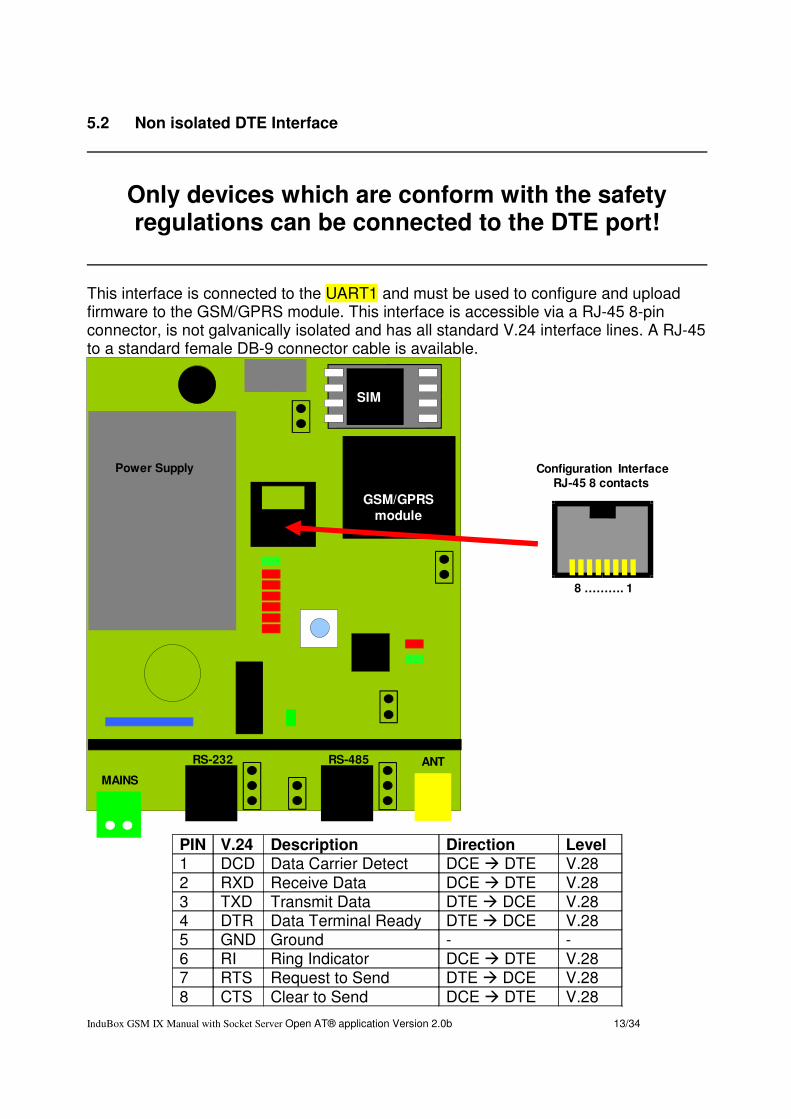
5.2 Non isolated DTE Interface
Only devices which are conform with the safetyregulations can be connected to the DTE port!
This interface is connected to the UART1 and must be used to configure and uploadfirmware to the GSM/GPRS module. This interface is accessible via a RJ-45 8-pinconnector, is not galvanically isolated and has all standard V.24 interface lines. A RJ-45to a standard female DB-9 connector cable is available.
PIN V.24 Description Direction Level1 DCD Data Carrier Detect DCE � DTE V.28 2 RXD Receive Data DCE � DTE V.283 TXD Transmit Data DTE � DCE V.284 DTR Data Terminal Ready DTE � DCE V.285 GND Ground - -6 RI Ring Indicator DCE � DTE V.287 RTS Request to Send DTE � DCE V.288 CTS Clear to Send DCE � DTE V.28
InduBox GSM IX Manual with Socket Server Open AT® application Version 2.0b 13/34
Power Supply
GSM/GPRS
module
MAINS
RS-232 ANTRS-485
SIM
Configuration InterfaceRJ-45 8 contacts
8 ………. 1

5.3 Isolated DTE Interfaces
Only devices which are conform with the safetyregulations can be connected to the DTE port!
The isolated interfaces are galvanically separated from the main circuits of the InduBoxGSM IX ; RxD and TxD are separated via an OptoCoupler, a second 5 Vdc powersupply is created via an aditional DC/DC convertor.
Two isolated interfaces are present :
• RS-232 3-wire & '+V' connected to SL6087 UART1
• RS-485 3-wire & '+V' connected to SL6087 UART2
5.3.1 Isolated RS-232 interface
• RS-232 Hardware Configuration
This interface is connected to the UART1, same V.24 bus as the non-isolated interfacedescribed above. The status LED's are connected to this V.24 bus.
PIN RS-232 Direction Level1 +V - - 5~25 Vdc in OR +5V' out (JP7)2 - - - -3 - - - -4 - RXD DCE � DTE V.285 - TXD DTE � DCE V.286 - GND' - V.287 - - - -8 - - - -
InduBox GSM IX Manual with Socket Server Open AT® application Version 2.0b 14/34
RS-485
MainsN L1
RS-232 InterfaceRJ-45 8 contacts
1 ………. 8 ANT

• RS-232 Software Configuration
This interface is full duplex and can be used on all possible baudrates up to 115200bps. This interface uses only RxD and TxD. DTR and RTS are not used, thus inactive.Be sure to disable those signals in the configuration of the InduBox GSM IX ;
at+ifc=0,0 no RTS/CTS flow controlat&d0 no DTR signal present
InduBox GSM IX Manual with Socket Server Open AT® application Version 2.0b 15/34
UART1
5V5V’
TxD
RxD
5V’
RXDTXDGND’
TTL/V.10
Level
Shift

5.3.2 Isolated RS-485 interface
• RS-485 Hardware Configuration
This interface is connected to the UART2. When data is transmitted/received on RS-485, the status LED's will not work. They are connected onto the UART1 bus.
PIN RS-485 Level1 +V - 5~25 Vdc in OR +5V' out (JP6)2 - B V.113 - - -4 - A V.115 - A V.116 - GND' -7 - B V.118 - - -
InduBox GSM IX Manual with Socket Server Open AT® application Version 2.0b 16/34
RS-232MainsN L1
1 ………. 8
RS-485 InterfaceRJ-45 8 contacts
ANT
A
B
dT
receiver
transmitter
~recENtraEN
120 E
JP5
JP4
UART2
5V’
B
A
GND'
RxD
TxD
Open - 20 ms - < 9600 bpsClose - 2 ms - >= 9600 bps
5V’
560 E
560 E
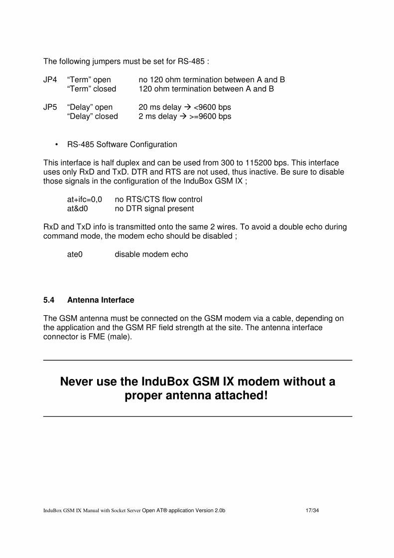
The following jumpers must be set for RS-485 :
JP4 “Term” open no 120 ohm termination between A and B“Term” closed 120 ohm termination between A and B
JP5 “Delay” open 20 ms delay � <9600 bps“Delay” closed 2 ms delay � >=9600 bps
• RS-485 Software Configuration
This interface is half duplex and can be used from 300 to 115200 bps. This interfaceuses only RxD and TxD. DTR and RTS are not used, thus inactive. Be sure to disablethose signals in the configuration of the InduBox GSM IX ;
at+ifc=0,0 no RTS/CTS flow controlat&d0 no DTR signal present
RxD and TxD info is transmitted onto the same 2 wires. To avoid a double echo duringcommand mode, the modem echo should be disabled ;
ate0 disable modem echo
5.4 Antenna Interface
The GSM antenna must be connected on the GSM modem via a cable, depending onthe application and the GSM RF field strength at the site. The antenna interfaceconnector is FME (male).
Never use the InduBox GSM IX modem without aproper antenna attached!
InduBox GSM IX Manual with Socket Server Open AT® application Version 2.0b 17/34

6. LED Indicators
There are 10 LED’s located onto the InduBox GSM IX modem printed circuit.
GSM yellow GSM Networkservice
DCE ON not registered on the networkSlow flash (2 s. OFF) registered on the network Quick flash (600 ms OFF)communication in progress
TXD red Transmit Data DTE � DCE TXD signal of the UART1 V.24 busRXD red Receive Data DCE � DTE RXD signal of the UART1 V.24 bus
DTR red Data TerminalReady
DTE � DCE DTR signal of the UART1 V.24 bus
DCD red Data Carrier Detect DCE � DTE DCD signal of the UART1 V.24 busRI red Ring Indicator DCE � DTE RI signal of the UART1 V.24 bus
MDE green OpenAT - Mode - Ref. OpenAT applicationdescription
WD green Watchdog “Tick” - Reflects the state of the WatchdogWD red ON during reset cycle -
5 V’ green Isolated 5Vdc powersupply
- OFF : no voltage presentON : voltage present
InduBox GSM IX Manual with Socket Server Open AT® application Version 2.0b 18/34
5V’
RXD
TXD
DCD
DTR
RI
GSM
WD
WD
MDE
Power Supply
GSM/GPRS
module
MAINS
RS-232 ANTRS-485
SIM

7 . Jumper Settings
The InduBox GSM IX modem has 6 jumpers. The functions of the jumpers will bedescribed in the paragraphs below.
Jumper Position DescriptionJP1 Open
ClosedGSM module normal operation (default)GSM module BOOT operation
JP2 - GSM module RESET – not usedJP4 “Term” Open
“Term” Closedno 120 ohm termination between A and B120 ohm termination between A and B
JP5 “Delay” Open“Delay” Closed
20 ms delay � <9600 bps2 ms delay � =>9600 bps
JP7 No Jumper“Meter”“5V”
RS-232 pin1 : no connectionRS-232 pin1 : '+V' 5~25 Vdc in (reset function)RS-232 pin1 : +5V' out
JP6 No jumper“Meter” “5V”
RS-485 pin1 : no connectionRS-485 pin1 : '+V' 5~25 Vdc in (reset function)RS-485 pin1 : +5V' out
InduBox GSM IX Manual with Socket Server Open AT® application Version 2.0b 19/34
JP2
Power Supply
GSM/GPRS
module
MAINS
RS-232 ANTRS-485
SIM
JP1
JP4
JP5
JP7 JP6
5V
Meter
5V
Meter
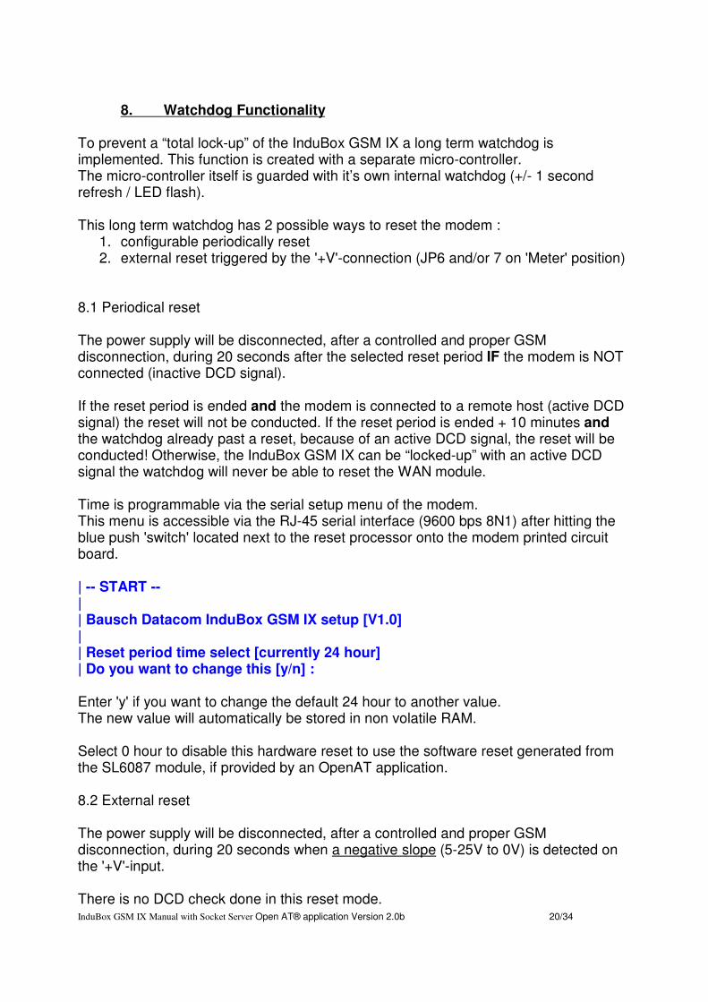
8. Watchdog Functionality
To prevent a “total lock-up” of the InduBox GSM IX a long term watchdog isimplemented. This function is created with a separate micro-controller. The micro-controller itself is guarded with it’s own internal watchdog (+/- 1 secondrefresh / LED flash).
This long term watchdog has 2 possible ways to reset the modem :1. configurable periodically reset2. external reset triggered by the '+V'-connection (JP6 and/or 7 on 'Meter' position)
8.1 Periodical reset
The power supply will be disconnected, after a controlled and proper GSMdisconnection, during 20 seconds after the selected reset period IF the modem is NOTconnected (inactive DCD signal).
If the reset period is ended and the modem is connected to a remote host (active DCDsignal) the reset will not be conducted. If the reset period is ended + 10 minutes andthe watchdog already past a reset, because of an active DCD signal, the reset will beconducted! Otherwise, the InduBox GSM IX can be “locked-up” with an active DCDsignal the watchdog will never be able to reset the WAN module.
Time is programmable via the serial setup menu of the modem.This menu is accessible via the RJ-45 serial interface (9600 bps 8N1) after hitting theblue push 'switch' located next to the reset processor onto the modem printed circuitboard.
| -- START --|| Bausch Datacom InduBox GSM IX setup [V1.0]|| Reset period time select [currently 24 hour]| Do you want to change this [y/n] :
Enter 'y' if you want to change the default 24 hour to another value.The new value will automatically be stored in non volatile RAM.
Select 0 hour to disable this hardware reset to use the software reset generated fromthe SL6087 module, if provided by an OpenAT application.
8.2 External reset
The power supply will be disconnected, after a controlled and proper GSMdisconnection, during 20 seconds when a negative slope (5-25V to 0V) is detected onthe '+V'-input.
There is no DCD check done in this reset mode. InduBox GSM IX Manual with Socket Server Open AT® application Version 2.0b 20/34
9. AT Command Interface
More information about the commands to the InduBox GSM IX modem, and theresponses from the InduBox GSM IX modem, are described in the Sierra Wireless(Wavecom) reference manual ‘AT commands interface guide’.
9.1 Most important AT commands
Verifying GSM receive signal quality
The modem will be able to establish a call only if the received GSM signal is of a sufficient
level.
The command AT+CSQ will return the reception level <rssi> of the signal sent by theclosest GSM Base Transceiver Station (BTS), as well the received bit error rate <ber>.When the SIM card is present and the PIN code has been entered, the commandAT+CSQ will return the signal level from the BTS on the subscribed operator network.When used without the SIM card, this command will simply indicate the closest BTSdue to the fact that the modem cannot identify the current subscription. It is thereforeadvisable to make this test with the SIM card present.
To verify the GSM signal quality, perform the following operations:Using a communication application, enter the command AT+CSQ.
The response is in the following format:
+CSQ: <rssi>,<ber> where...
rssi indicates the reception level (Received Signal. Strength Indication).ber indicates the received bit error rate (Bit Error Rate).
How to interpret the results :
The InduBox GSM IX functions correctly with a minimum <rssi> of between 12 and 15.Below 10 the signal is insufficient, the modem cannot function depending on the geo-graphical situation. Above 15 the signal is of a sufficient level.
The InduBox GSM IX functions also correctly with a ‘ber’ = 0.
PIN-code
The PIN code is essential in order to make a call or to accept a call from the GSM net-work. The PIN code is held on the SIM card and can be modified by the user.
To verify a previously entered PIN code or see if the SIM card is working properly, usea communication application and enter the command AT+CPIN.
(Ensure that a valid SIM card is present in the SIM card reader in the modem)
InduBox GSM IX Manual with Socket Server Open AT® application Version 2.0b 21/34
Verify a PIN code and see if the SIM card is working properly
AT+CPIN?The InduBox GSM IX must return:+CPIN : READY
AT+CFUN
Do not simply cut off the supply of the InduBox GSM IX modem whilst in communicationor dialogue without having first detached from the network operator.To avoid network congestion when powering down the modem, it is essential to firstexecute the command AT+CFUN=0.If this is not done, then, in certain cases the modem can remain registered on the net-work.
When you want to power down (‘hard’ reset) the unit which is in dialog mode and not incommunication or you want to do a 'warm' reset:
AT+CFUN=0OKThe modem will return OK and is no longer registered on the network. The SL6087 GSM/GPRS radio module is put into standby and the power may then be removed.
AT+CFUN=1OKThe InduBox GSM IX will perform a 'warm' reset.
InduBox GSM IX Manual with Socket Server Open AT® application Version 2.0b 22/34
10 ‘Socket Server’ application in Open AT ®
10.1 Introduction
This manual is the reference manual for configuring the Socket Server Open AT® (1).application.
The Socket Server Open AT® application is created for the Bausch Datacom InduBoxGSM modems (2). The InduBox GSM IX modem is using the Sierra Wireless SL6087GSM/GPRS module.
Thanks to the Socket Server Open AT® application, a non IP enabled device (like anItron SL7000 C&I electricity meter), connected to the Indubox modem, will beaccessible over a GPRS link.
10.2 General Description
CSD (Circuit Switched Data) data communication with GSM modems has a similarbehavior as connections with standard PSTN modems over a POTS (Plain OldTelephone System) line.
In CSD answering mode (auto answer active s0=1), the Indubox modem will sent theunsolicited CONNECT 9600 respons when a successful connection is established witha remote originating modem. When the remote modem is disconnecting the connection,the respons NO CARRIER will be transmitted.
When using GPRS the situation is completely different. TCP/IP is used, all data will besent in packets and routed over an IP packet switched network.
Thanks to the Socket Server Open AT® application a CSD answering mode will besimulated when using communication over a GPRS link.When the Open AT® application is started in SCKserv mode, a GPRS/APN connectionwill be automatically established and maintained. After a successful GPRS/APNconnection the InduBox modem will be part of an IP network (Internet or Intranet) and
(1) The AirPrime SL6087 GSM/GPRS processor is a product of Sierra Wireless (Wavecom). Itfeatures 2G quad-band (850/900/1800/1900 MHZ) connectivity and has industrial features like anextended temperature range (-40°C to +85°C).The SL6087 GSM/GPRS processor integrated in the InduBox GSM IX can be used as a simplemodem controlled via AT commands or it can host a standard ANSI C/C++ application and act asa single processor for the customer solution because it is delivered with the full set of Plug-Ins forOpen AT® OS, enabling Bausch Datacom to easily add TCP/IP and Internet security.Thanks to the Bausch ‘Socket Server’ Open AT® application (embedded in the SL6087processor) the need for an external processor is eliminated and the total size and cost of the finalproduct is reduced.
(2) The Socket Server Open AT® can be used in InduBox GSM IV (Q24PL GSM/GPRS module ofSierra Wireless – Wavecom -), InduBox GSM VII and VIII (Airprime Q2686 GSM/GPRS moduleof Sierra Wireless – Wavecom -), InduBox GSM IX (SL6087 GSM/GPRS module of SierraWireless – Wavecom-), but also on the DinBox GSM/GPRS (Q24PL).
InduBox GSM IX Manual with Socket Server Open AT® application Version 2.0b 23/34

will have an IP number. The Open AT® application will start a TCP socket server(listener) service and will listen to a predefined PORT.
When a remote TCP client establishes a connection with the InduBox modem, theunsolicited respons CONNECT 9600 will be transmitted. When the TCP client isdisconnecting the connection, the respons NO CARRIER will be transmitted.
More information about the different modes of the Socket Server Open AT® applicationare described in the following sections.
10.3 Basic Setup
When using the Socket Server Open AT® application the serial port of the InduBoxmodem can only be used with the following parameters :
Speed : 9600 bpsAsync format : 8N1Flow control : none (no RTS needed from DTE)V.24 DTR signal : none (no DTR needed from DTE)
Basically only RXD/TXD and GND are needed to use the Open AT® application.It’s possible to use the isolated 3-wire RS-232 and 2-wire RS-485 interfaces of theInduBox GSM IX modem.
10.4 Possible Modes
There are 3 possible working modes into the Socket Server Open AT® application :
10.4.1 CSD mode
The modem is acting like a normal GSM CSD data modem in autoanswer mode (s0=1).When a remote modem dials-in the unsolicited respons CONNECT 9600 is sent.When the connection is disconnected NO CARRIER will be sent. During CSD “datamode” the modem is 100% transparent.
During “idle state mode” the modem is able to receive a SMS message and check themessage content. More info on the SMS message content info below.
10.4.2 GPRS mode
Same function as CSD described above, but the modem has received APN GPRSparameters via a SMS message. APN server name, username, password and DNS infois entered, but there is no GPRS attachment or APN connection.
This mode is implemented to allow DOTA (Download Over The Air) upgrade via a FTPhost. This function is described below.InduBox GSM IX Manual with Socket Server Open AT® application Version 2.0b 24/34
During “idle state mode” the modem is able to receive a SMS message and check themessage content. More info on the SMS message content info below.
10.4.3 SCKServ mode
In this mode, the modem will automatically be connected to GPRS/APN and a TCPsocket server (listen) service will be started. The APN connection and the socket listenmode will be checked regularly (60 seconds) so that the modem is always ready for aTCP socket client.
When a remote TCP client establishes a connection with the InduBox modem, theunsolicited respons CONNECT 9600 will be transmitted. When the TCP client isdisconnecting the connection, the respons NO CARRIER will be transmitted.
During “data mode” the modem is 100% transparent.During “idle state mode” the modem is able to receive a SMS message and check themessage content. More info on the SMS message content info below.
10.5 How to switch between the 3 modes via SMS
Switching between the modes described above is done via (text) SMS messages.
Note:· Each line must be terminated with a <CR><LF>, also the last (End) line· Each character is case sensitive.
In a default state CSD mode is selected. No GPRS parameters are saved.
10.5.1 Switch to GPRS mode
A SMS with the following content must be sent to the modem;
InduBox startup.iniLink : GPRSAPN : “proximus.internet.be”APNUN : “username”APNPW : “password”DNS1 : “”DNS2 : “”End
When the modem receives the SMS message as described above, the modem willsave all the received parameters, restart and enter the GPRS mode. As explainedabove; this mode acts the same as CSD but all APN parameters are know andprogrammed. This mode exists to do an FTP upgrade as explained in next chapter.
InduBox GSM IX Manual with Socket Server Open AT® application Version 2.0b 25/34

10.5.2 Switch to SCKserv mode
A SMS with the following content must be sent to the modem;
InduBox startup.iniLink : SCKservAPN : “proximus.internet.be”APNUN : “username”APNPW : “password”DNS1 : “”DNS2 : “”Port : 404End
When the modem receives an SMS message as described above, the modem will saveall the received parameters, restart and enter the SCKserv mode. After the GSMregistration the modem will automatically establish a connection to the GPRS networkand the APN. The received IP address will be sent onto the serial port as an unsolicitedrespons and the socket server service will start automatically.
10.5.3 Switch to CSD mode
It’s always possible to go back to the default CSD mode via the following SMS;
InduBox startup.iniLink : CSDEnd
When the modem receives an SMS message as described above, the modem willrestart, and enter the CSD mode.
10.6 How to switch between the 3 Modes via “at” commands
Switching between the modes described above can also be done locally, via standard“at” commands.
Connect the InduBox GSM IX modem, via the Bausch RJ-45 to DB-9 serial cable, to astandard COM port of a PC. Use a standard serial communication program likeWindows Hyperterminal, configured onto the correct COM port / 9600 bps / 8N1 / noflowcontrol.
Don't change the currect settings of the modem !
– modem echo is off [ate0] : no characters will be send back (blind typing)
– no flowcontrole [at+ifc=0,0] : CTS is not active
InduBox GSM IX Manual with Socket Server Open AT® application Version 2.0b 26/34

Mode switching command
AT/LINK = <CSD|GPRS|SCKserv>
Specific GPRS/SCKserv parameters commands
AT/APN= “proximus.internet.be”AT/APNUN=”username”AT/APNPW=”password”AT/DNS1=””AT/DNS2=””AT/TCPPORT=””
Specific DOTA parameters commands
AT/FTPADDRESS=”12.15.15.62”AT/FTPPORT=”21”AT/FTPFILE=”file.txt”AT/FTPSIZE=”262
Configuration overview command
AT/CONFIG?
10.7 DOTA upgrade (optional)
DOTA upgrade is done via FTP.A SMS with the following content must be sent to the modem;
InduBox FTP upgreadeFTP : 213.219.182.110:21User : usernamePwd : passwordFile : filename.extSize : 15124End
After receiving the SMS the modem will try to make a connection to a FTP server:port.
When in CSD mode: nothing will be done (no GPRS parameters) GPRS mode: the modem will do a GPRS attach, APN connection, …SCKserv mode: stop socket listen service, the modem was already connected to
GPRS, APN, …
After downloading the file, the size will be verified.InduBox GSM IX Manual with Socket Server Open AT® application Version 2.0b 27/34

If not equalThe upgrade process stops and the modem will restart as nothing has happened.
If equalThe new OpenAT application will be loaded and the modem will restart.
InduBox GSM IX Manual with Socket Server Open AT® application Version 2.0b 28/34

A. EC-Declaration of conformity
standard CE + TST25-3 (additional extended immunity tests)
EN61000-3-2 Electromagnetic compatibility, part 3, section 2Limits for harmonic current emissions.
EN61000-3-3 Electromagnetic compatibility, part 3, section 3Limitations of voltage fluctuation and flicker.
EN61000-4-2 Electromagnetic compatibility, part 4, section 2Electrostatic discharge immunity test.
CISPR24 : 4 KV contact / 8 KV air TST25-3 : 8 KV contact (20 +/- contacts) / 15 KV air (20 +/-
discharges)
EN61000-4-3 Electromagnetic compatibility, part 4, section 3Radiated fields immunity test.CISPR24 : 10 V/m 80 MHz - 2000 Mhz, mod. AM 80% 1KHz TST25-3 : 30 V/m 80 MHz - 2000 Mhz, mod. AM 80% 1KHz
ENV50204 Electromagnetic compatibility, Basic immunity standard, RadiatedElectromagnetic field from digital radio telephones immunity test.CISPR24 : 10 V/m 890-2400 MHz, 1% freq step, 1s dwell, 50%
duty, 200 Hz repetition time
TST25-3 : 30 V/m 890-2400 MHz, 1% freq step, 1s dwell, 50% duty, 200 Hz repetition time
EN61000-4-4 Electromagnetic compatibility, part 4, section 4Electrical fast transient/burst immunity test.CISPR24 : 0.5 KV and 1 KV 5/50 ns, 5 Khz rep. freq on AC
mainsTST25-3 : 2 KV and 4 KV, 5/50 ns, 5 Khz rep freq on AC mains
EN61000-4-5 Electromagnetic compatibility, part 4, section 5Surge immunity test.CISPR24 : 10 pulses 1 KV 1,2/50 µs (5+ 5-) on AC mainsTST25-3 : 6 KV pulses
EN61000-4-6 Electromagnetic compatibility, part 4, section 6Conducted immunity test.CISPR24 : 3 V 0.15 MHz - 80 MHz, mod. 80% at 1 Khz on
mainsTST25-3 : 10 V 0.15 MHz - 80 MHz, mod. 80% at 1 Khz on
mains
Magnetic fields applied to all accessible surfaces1000 At (ampere turns) – 1A on 1000 turns
InduBox GSM IX Manual with Socket Server Open AT® application Version 2.0b 29/34
EN61000-4-8 Electromagnetic compatibility, part 4, section 8Power frequency magnetic field immunity test.CISPR24 levels
EN61000-4-11 Electromagnetic compatibility, part 4, section 11Voltage dips, short interruptions and voltage variations immunity
test.CISPR24 levels
EN61000-4-18 Oscillatory waves1 MHz 2,5 KV, rep rate 400 Hz applied on mains in common mode100 Khz 2,5 KV, rep rate 40Hz applied on mains in common mode1 MHz 1KV, rep. Rate 400 Hz applied on mains in differential mode100 MHz 1KV, rep. Rate 40 Hz applied on mains in differential
mode
EN55022 Limits and methods of measurement of radiodisturbance characteristics of ITE-equipment.
EN55022 class B limits (AV - QP)Radiated emission : 30 - 1000 MHzConducted emission (CISPR16) : 0.15 - 30 MHz
EN55024 performance criteria for immunity tests
EN61000-6-3 performance criteria for emission tests
InduBox GSM IX Manual with Socket Server Open AT® application Version 2.0b 30/34
InduBox GSM IX Manual with Socket Server Open AT® application Version 2.0b 31/34

InduBox GSM IX Manual with Socket Server Open AT® application Version 2.0b 32/34
InduBox GSM IX Manual with Socket Server Open AT® application Version 2.0b 33/34

InduBox GSM IX Manual with Socket Server Open AT® application Version 2.0b 34/34