induccion direcional
DESCRIPTION
induccion direccionalTRANSCRIPT
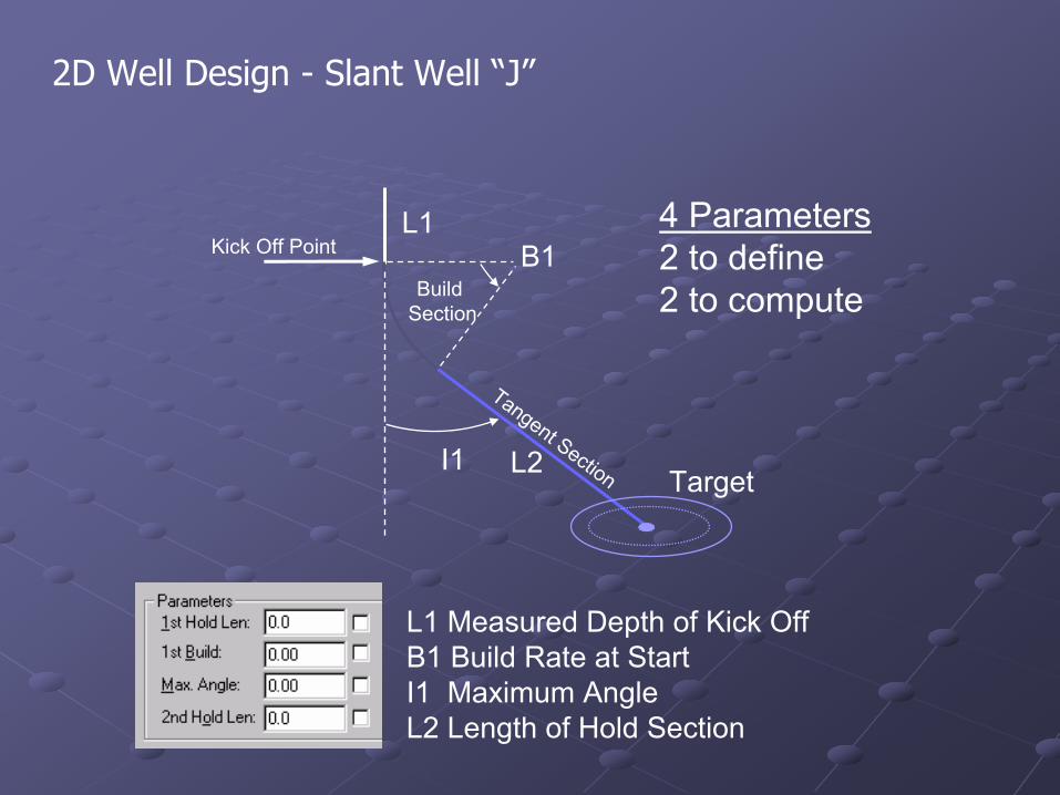
2D Well Design - Slant Well “J”
L1 Measured Depth of Kick OffB1 Build Rate at StartI1 Maximum AngleL2 Length of Hold Section
4 Parameters2 to define2 to compute
Kick Off PointL1
B1
I1 L2 Target
Tangent Section
Build Section
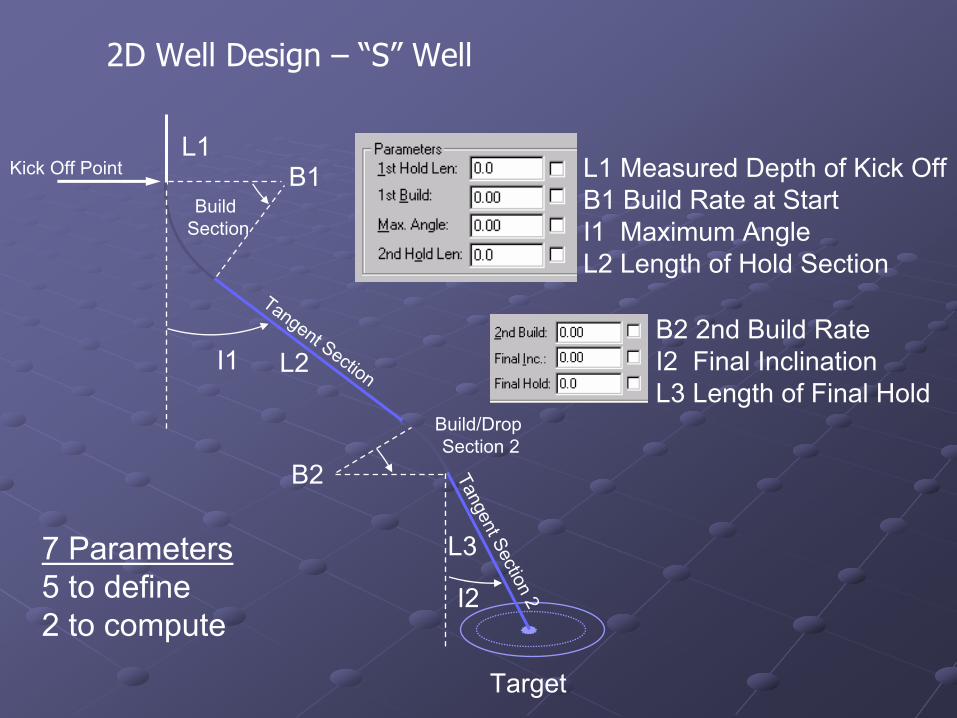
2D Well Design – “S” Well
B2 2nd Build RateI2 Final InclinationL3 Length of Final Hold
Kick Off PointL1
B1
I1 L2
Target
Tangent Section
Build Section
Build/Drop Section 2
Tangent Section 2
B2
L3
I2
L1 Measured Depth of Kick OffB1 Build Rate at StartI1 Maximum AngleL2 Length of Hold Section
7 Parameters5 to define2 to compute
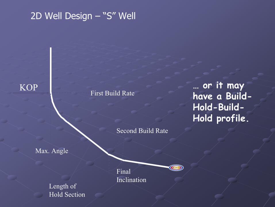
… or it may have a Build-Hold-Build-Hold profile.
KOP
Max. Angle
First Build Rate
Length of Hold Section
Second Build Rate
Final Inclination
2D Well Design – “S” Well
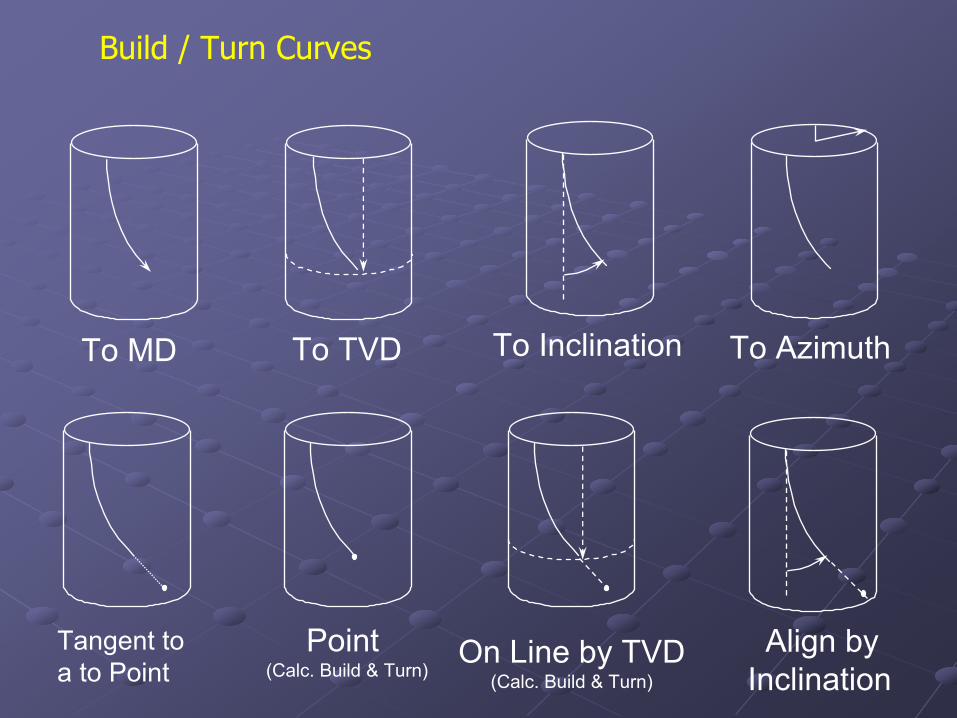
To MD To TVD
Tangent to a to Point
Point (Calc. Build & Turn)
On Line by TVD(Calc. Build & Turn)
To AzimuthTo Inclination
Align by Inclination
Build / Turn Curves
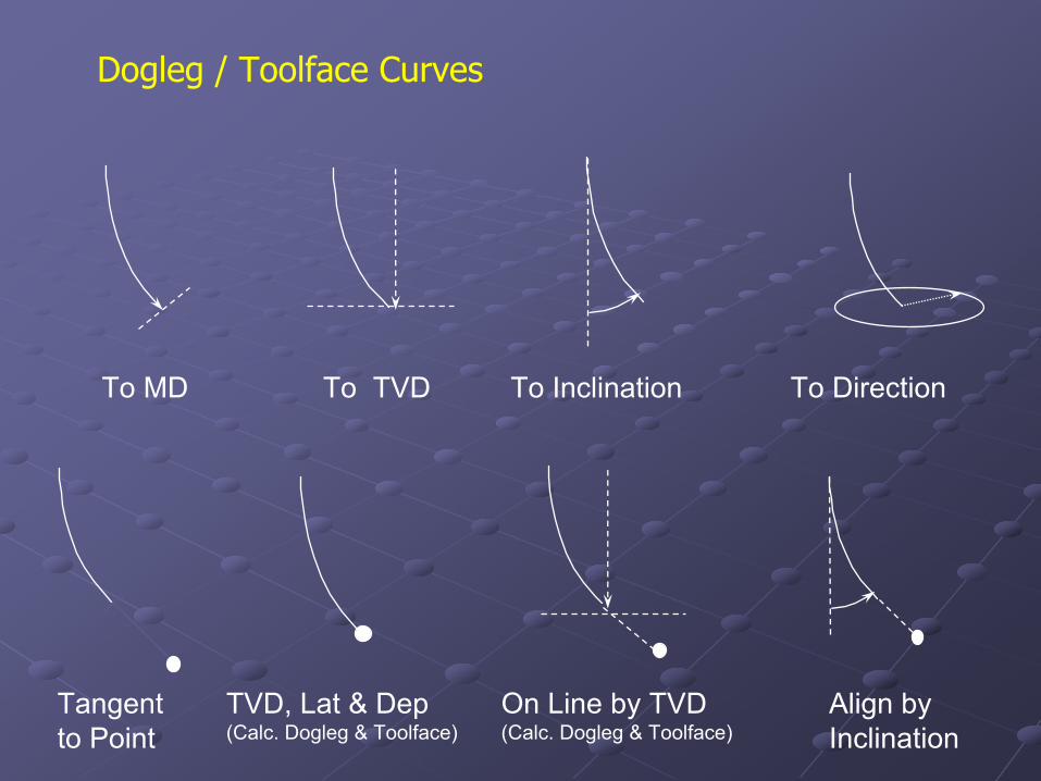
Dogleg / Toolface Curves
To MD To TVD To Inclination To Direction
On Line by TVD(Calc. Dogleg & Toolface)
TVD, Lat & Dep(Calc. Dogleg & Toolface)
Tangent to Point
Align by Inclination
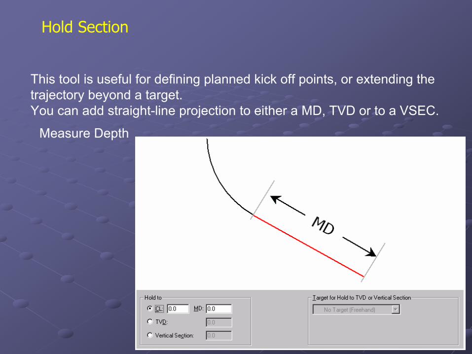
Hold Section
This tool is useful for defining planned kick off points, or extending the trajectory beyond a target.You can add straight-line projection to either a MD, TVD or to a VSEC.
Measure Depth
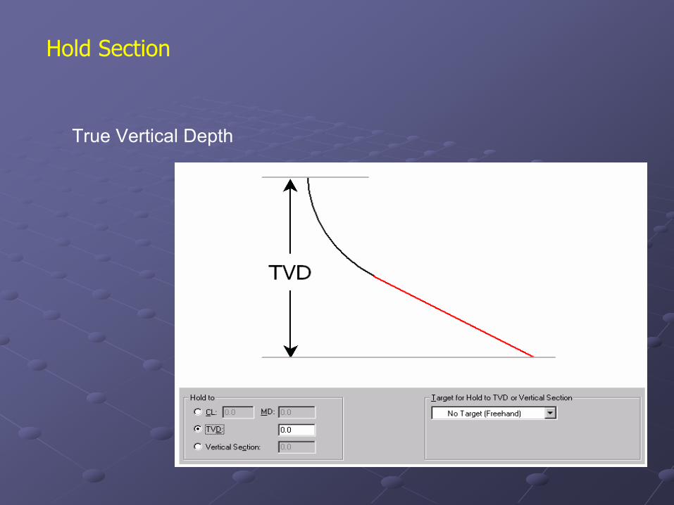
Hold Section
True Vertical Depth
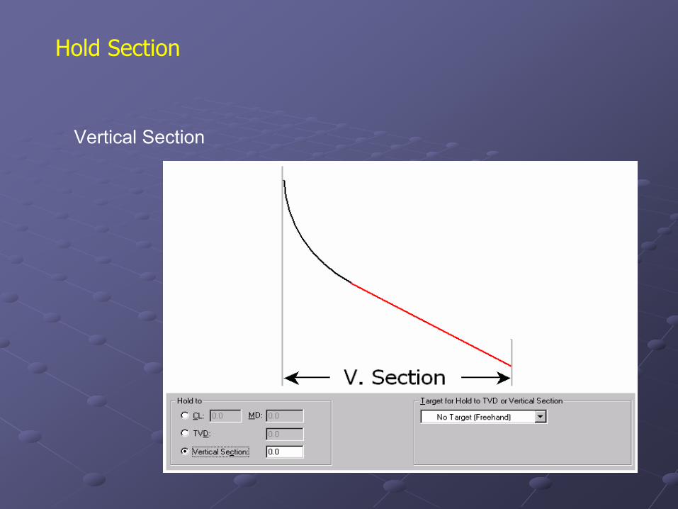
Hold Section
Vertical Section
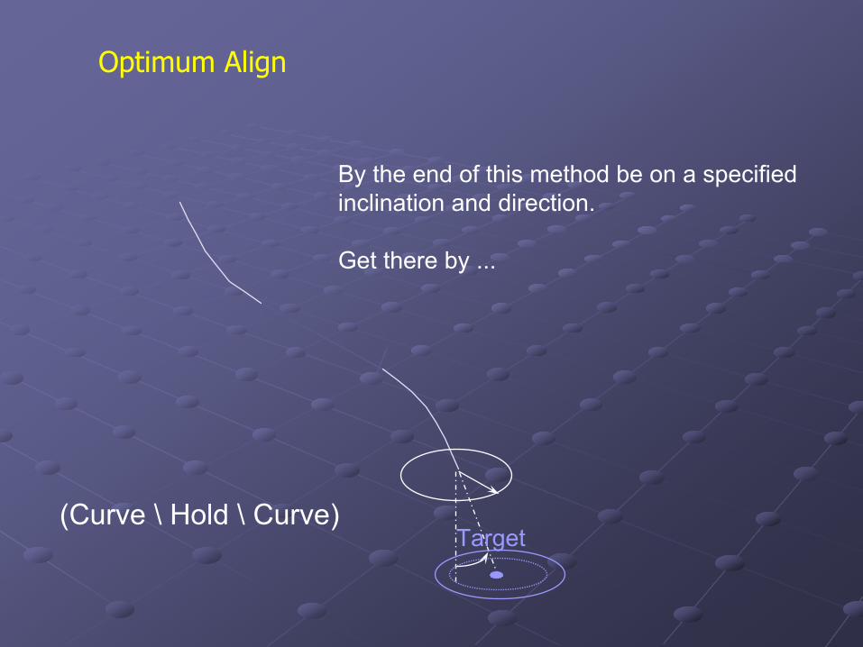
Optimum Align
By the end of this method be on a specifiedinclination and direction.
Get there by ...
(Curve \ Hold \ Curve)Target
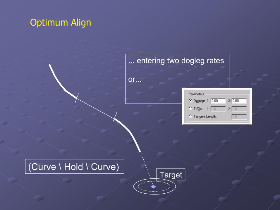
Optimum Align
(Curve \ Hold \ Curve)
... entering two dogleg rates
or...
Target
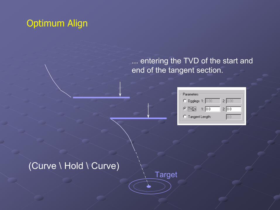
Optimum Align
(Curve \ Hold \ Curve)
... entering the TVD of the start and end of the tangent section.
Target
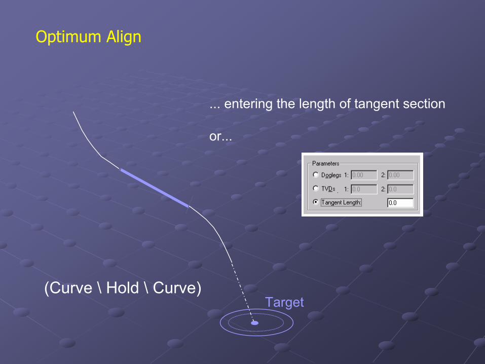
Optimum Align
(Curve \ Hold \ Curve)
... entering the length of tangent section
or...
Target
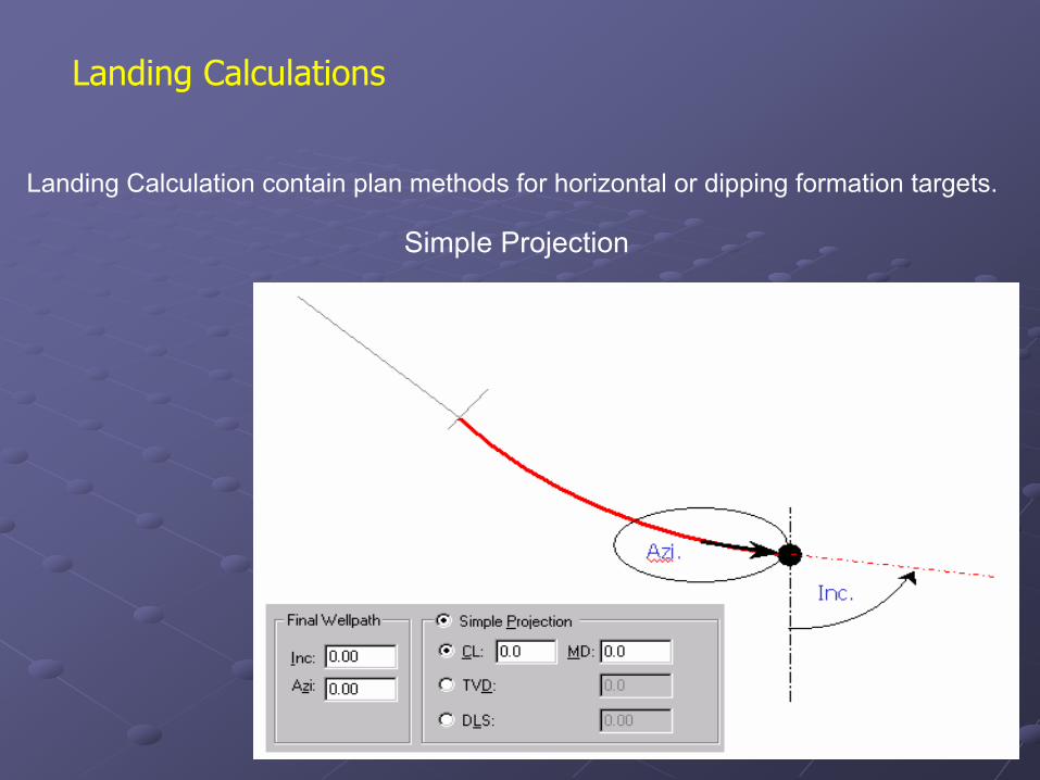
Landing Calculations
Landing Calculation contain plan methods for horizontal or dipping formation targets.
Simple Projection
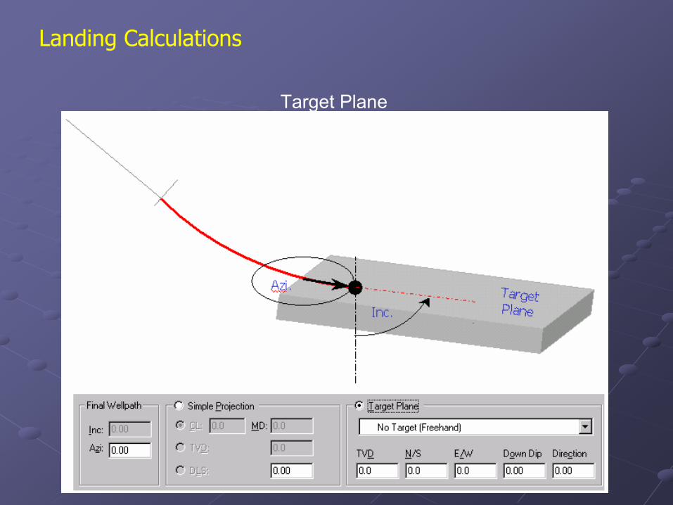
Landing Calculations
Target Plane
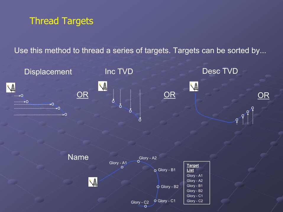
Use this method to thread a series of targets. Targets can be sorted by...
Displacement Inc TVD Desc TVD
OR OR
Name
OR
Glory - A1Glory - A2
Glory - B1
Glory - B2
Glory - C1Glory - C2
Target ListGlory - A1Glory - A2Glory - B1Glory - B2Glory - C1Glory - C2
Thread Targets
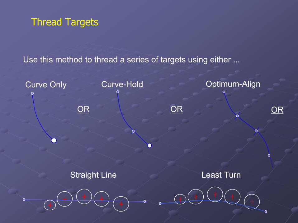
Thread Targets
Curve Only Curve-Hold Optimum-Align
Use this method to thread a series of targets using either ...
OR OR OR
Straight Line Least Turn
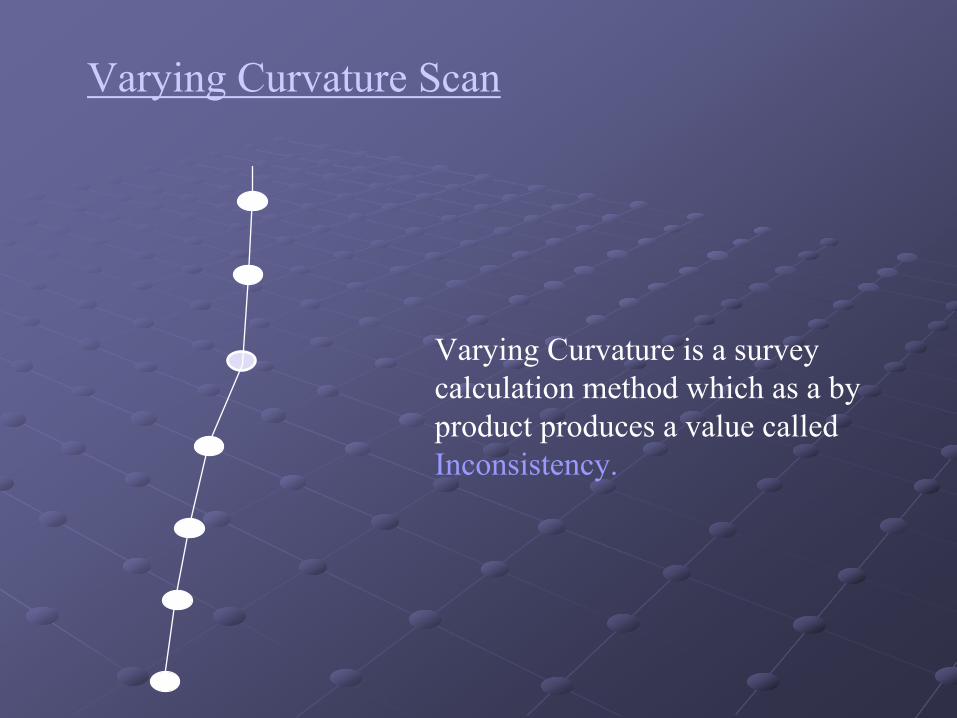
Varying Curvature Scan
Varying Curvature is a survey calculation method which as a by product produces a value called Inconsistency.
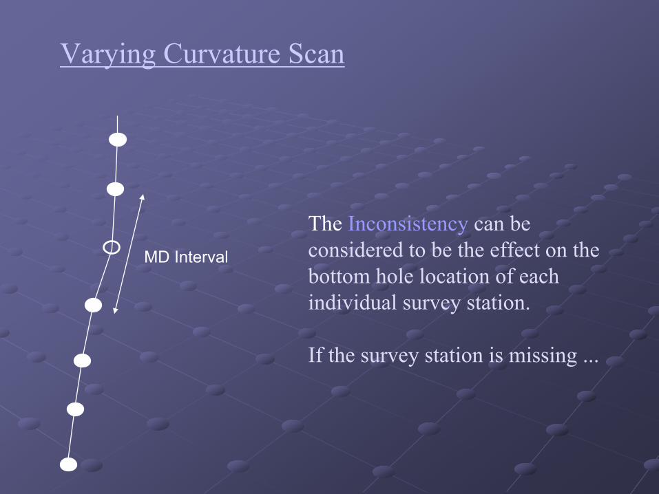
MD Interval
The Inconsistency can be considered to be the effect on the bottom hole location of each individual survey station.
If the survey station is missing ...
Varying Curvature Scan
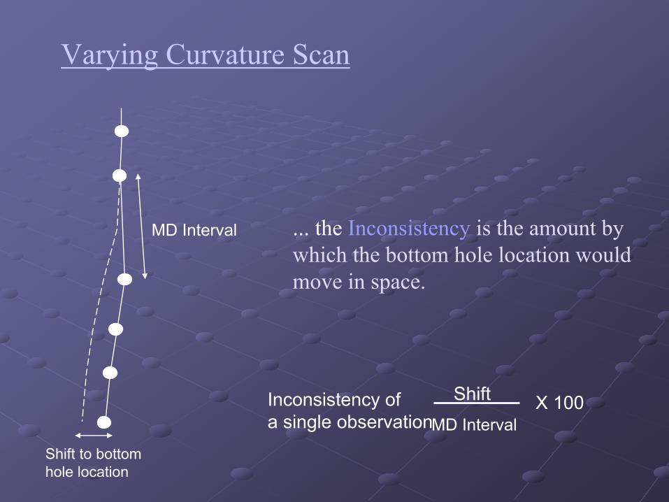
Inconsistency of a single observation
ShiftMD Interval
X 100
Shift to bottom hole location
MD Interval ... the Inconsistency is the amount by which the bottom hole location would move in space.
Varying Curvature Scan