inductors & inductance - cie-wc.edu · inductors & inductance when induction occurs in an...
TRANSCRIPT
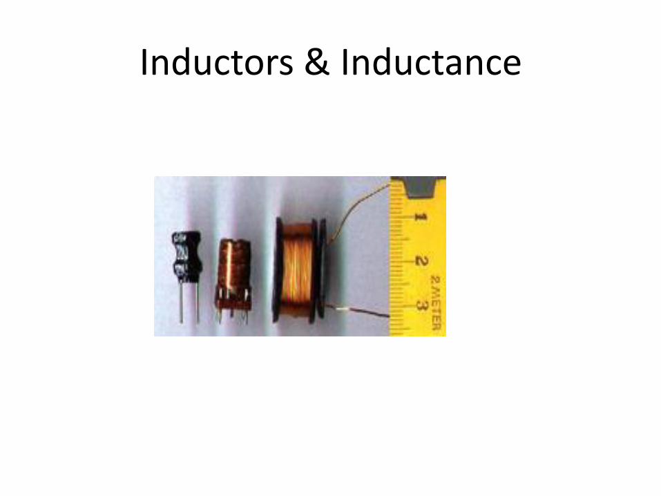
Inductors & Inductance
Electronic Components
Inductors & Inductance
Induction
In 1824, Oersted discovered that current passing though a coil created a magnetic field capable of shifting a compass needle. Seven years later, Faraday and Henry discovered just the opposite. They noticed that a moving magnetic field would induce current in an electrical conductor. This process of generating electrical current in a conductor by placing the conductor in a changing magnetic field is called electromagnetic induction or just induction. It is called induction because the current is said to be induced in the conductor by the magnetic field.
Inductors & Inductance
Inductors & Inductance
Induction is measured in unit of Henries (H) which reflects this dependence on the rate of change of the magnetic field. One henry is the amount of inductance that is required to generate one volt of induced voltage when the current is changing at the rate of one ampere per second. Note that current is used in the definition rather than magnetic field. This is because current can be used to generate the magnetic field and is easier to measure and control than magnetic flux.
Inductors & Inductance When induction occurs in an electrical circuit and affects the flow of electricity it is called inductance, L. Self-inductance, or simply inductance, is the property of a circuit whereby a change in current causes a change in voltage in the same circuit. When one circuit induces current flow in a second nearby circuit, it is known as mutual-inductance. The image to the right shows an example of mutual-inductance. When an AC current is flowing through a piece of wire in a circuit, an electromagnetic field is produced that is constantly growing and shrinking and changing direction due to the constantly changing current in the wire. This changing magnetic field will induce electrical current in another wire or circuit that is brought close to the wire in the primary circuit. The current in the second wire will also be AC and in fact will look very similar to the current flowing in the first wire.
Inductors & Inductance An electrical transformer uses inductance to change the voltage of electricity into a more useful level. In nondestructive testing, inductance is used to generate eddy currents in the test piece. It should be noted that since it is the changing magnetic field that is responsible for inductance, it is only present in AC circuits. High frequency AC will result in greater inductive reactance since the magnetic field is changing more rapidly. The property of self-inductance is a particular form of electromagnetic induction.
Self-inductance is defined as the induction of a voltage in a current-carrying wire when the current in the wire itself is changing. In the case of self-inductance, the magnetic field created by a changing current in the circuit itself induces a voltage in the same circuit. Therefore, the voltage is self-induced.
Inductors & Inductance The term inductor is used to describe a circuit element possessing the property of inductance and a coil of wire is a very common inductor. In circuit diagrams, a coil or wire is usually used to indicate an inductive component. Taking a closer look at a coil will help understand the reason that a voltage is induced in a wire carrying a changing current. The alternating current running through the coil creates a magnetic field in and around the coil that is increasing and decreasing as the current changes. The magnetic field forms concentric loops that surround the wire and join to form larger loops that surround the coil as shown in the image below. When the current increases in one loop the expanding magnetic field will cut across some or all of the neighboring loops of wire, inducing a voltage in these loops. This causes a voltage to be induced in the coil when the current is changing.
Inductors & Inductance
Inductors & Inductance
Lenz's Law Soon after Faraday proposed his law of induction, Heinrich Lenz developed a rule for determining the direction of the induced current in a loop. Basically, Lenz's law states that an induced current has a direction such that its magnetic field opposes the change in magnetic field that induced the current. This means that the current induced in a conductor will oppose the change in current that is causing the flux to change. Lenz's law is important in understanding the property of inductive reactance, which is one of the properties measured in eddy current testing.
Inductors & Inductance
Inductors & Inductance
As in the definition of capacitance, we have a factor of 1/2, which is purely a matter of definition. The quantity L is called the inductance of the inductor, and we see that its units must be joules per ampere squared. This clumsy combination of units is more commonly abbreviated as the henry, 1 henry = 1 J/A2. Rather than memorizing this definition, it makes more sense to derive it when needed from the definition of inductance. Many people know inductors simply as “coils,” or “chokes,” and will not understand you if you refer to an “inductor,” but they will still refer to L as the “inductance.”
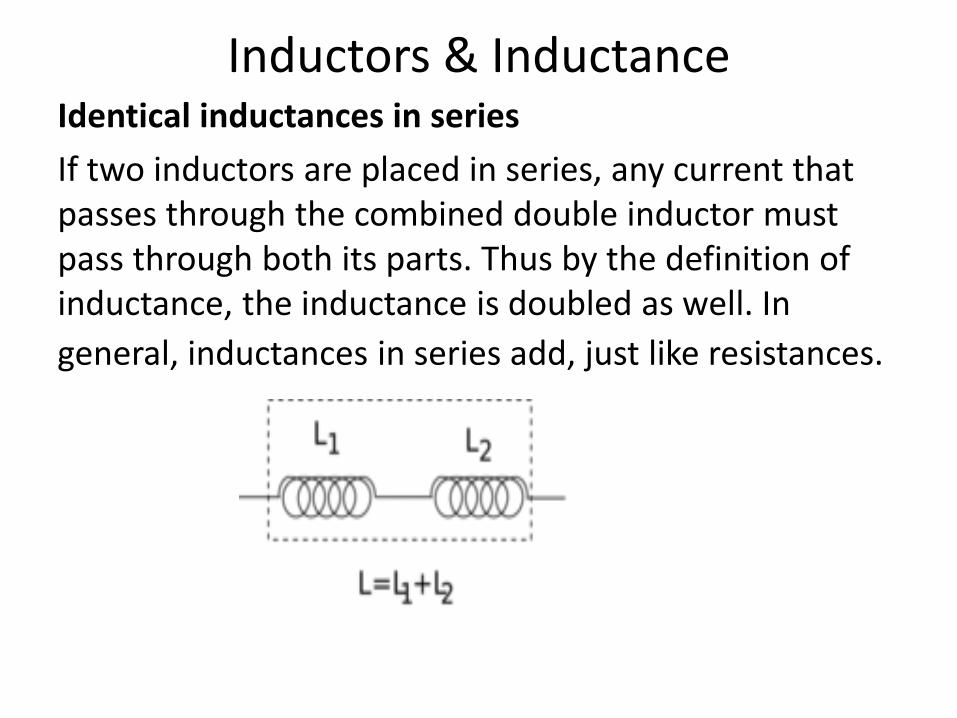
Inductors & Inductance Identical inductances in series
If two inductors are placed in series, any current that passes through the combined double inductor must pass through both its parts. Thus by the definition of inductance, the inductance is doubled as well. In
general, inductances in series add, just like resistances.
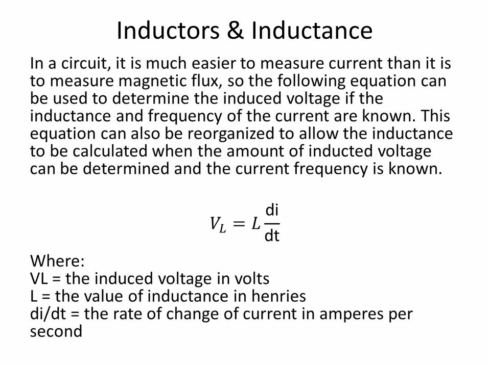
Inductors & Inductance