industrial 3d measurement techniques with...
TRANSCRIPT

Text
Pict
ure
Text
Pict
ure
Text
Pict
ure
Text
Pict
ure
KissSoft User Conference
Anil Gupta 25-Nov-2015
Industrial3D MeasurementTechniques with ATOS

Text
Pict
ure
Text
Pict
ure
Text
Pict
ure
Text
Pict
ure
GOM – Precise Industrial 3D Metrology
GOM is a technology companyGlobal industrial partner with over 20 years experience in the developmentand production of optical 3D metrology solutions
Hardware and Software
Material and component testing3D coordinate measurement
Source: LiA, University Paderborn

Text
Pict
ure
Text
Pict
ure
Text
Pict
ure
Text
Pict
ure
GOM – Precise Industrial 3D Metrology
Projected pattern Regular pattern Stochastic pattern Point markers
Know-how:
· Digital image processing· 3D coordinate measurement techniques· Quality control· Material parameters· Automation

Text
Pict
ure
Text
Pict
ure
Text
Pict
ure
Text
Pict
ure
GOM – Precise Industrial 3D Metrology
GOM Network
GOM Group with 9 companies and branches
Continuous growth to over 350 employees within GOM Group
36 sales and support partners with over 55 offices worldwide
700 employees in worldwide network

Text
Pict
ure
Text
Pict
ure
Text
Pict
ure
Text
Pict
ure
GOM – Precise Industrial 3D MetrologyOptical metrology has become a standard in the development and production ofindustrial products
Automotive industry Aerospace industry Research andUniversities
Consumer goodsindustry
GOM measurement systems are used worldwide inindustry, research institutions and universities

Text
Pict
ure
Text
Pict
ure
Text
Pict
ure
Text
Pict
ure
GOM – Precise Industrial 3D Metrology Customers (Extract)
Over 8000 system installations worldwide
AutomotiveAudi, Avtovaz, Bentley, BMW,Chrysler, Daihatsu Motor,Daimler, Fiat, Ford, GM , Honda ,Hyundai , Isuzu, Jaguar, Kia,Land Rover, McLaren, Modenas,NAZA, Nissan, Opel, Porsche,PSA, Renault, Seat, Skoda,Subaru, Suzuki, Tata Motors,Toyota, VW, Volvo, Temsa, …
TurbinesABB Turbo systems , Alstom,Aviadvigatel, BTL, Chromalloy,Elbar Sulzer, E.ON, GorbynovAviation, Honeywell, Howmet,IMA Dresden, MTU, Pratt &Whitney, Rolls Royce, Salut,Saturn, Siemens PG, Snecma,Solar Turbines, Triumph, TurbineServices, …
Comsumer GoodsAdidas, Asics, ASUS, Blaupunkt,Bosch, Braun, Ching Luh Shoes,Ecco, FisherPrice, Foxconn, Fuji,Gillette, Greenpoint, Hilti, Lego,LG Electronic Mattel, Microsoft,Motorola, Nautor, Nike, Nokia,Philips, Reebok , Samsung,SANYO, Siemens, Sony, Stihl,Villeroy+Boch, Walt Disney, …
Material SupplierACTech, Alfa Laval, Alcan(Alusuisse), Arcelor, , BASF,Bayer, Corning, DuPont,EXXON, Hydro (VAW), PierburgKolbenschmidt, Salzgitter,Shell, Tata Steel, ThyssenKrupp, Thyssen Nirosta, TokaiRubber Industries, Voest AlpineStahl, …
Automotive SuppliersAutomotive Lighting, Batz,Bertrandt, Bosch, Bombardier,Bridgestone, Carcoustics, DAAZ,Dräxlmaier, Faurecia, GeorgFischer, Gienanth, Goodyear,Hella, Johnson Controls, KautexTextron, Michelin, Nothelfer,Pininfarina, Siemens, Thule,ThyssenKrupp, ZF Sachs, …
AerospaceAirbus, Air Force Research Labs,Aselsan, Boeing, Cessna, ChromAlloy, DLR, DNV, EADS,Eurocopter, FAA, FOI, Goodrich,Gorbynov Aviation, HansenTransmissions, Hydro, IMPO,JAXA, Lockheed Martin, NASA,NLR, Northrop Grumman,ONERA, Vulcan Air, VZLÚ, …

Text
Pict
ure
Text
Pict
ure
Text
Pict
ure
Text
Pict
ure
GOM – Precise Industrial 3D MetrologyGOM solutions simplify complex measurementtasks in product development and production
Improving product quality and productionthroughput
Shortening of development processes
Improving quality assurance throughout the entireproduct life cycle
Cost reduction
Improvement of competitiveness

Text
Pict
ure
Text
Pict
ure
Text
Pict
ure
Text
Pict
ure
8Presentation title | Presenters name
How ATOS works ?
Full-field component measurement
3D Data for follow-on processes
Functionality and measurement process
Inspection software: Evaluation workflow

Text
Pict
ure
Text
Pict
ure
Text
Pict
ure
Text
Pict
ure
9Presentation title | Presenters name
Full-field component measurement
Optical 3D scanner for three-dimensional component measurement and inspection
Any object size, surface characteristics and component complexity
Full-field, precise 3D coordinates
Non-contact

Text
Pict
ure
Text
Pict
ure
Text
Pict
ure
Text
Pict
ure
10Presentation title | Presenters name
3D Data for follow-on processes
ATOS provides 3D Mesh (STL)High resolution for finest detailsMeasurement of small radii
CNC Machining
Data for follow-on processes
Quality Control
Additive Manufacturing
Reverse Engineering

Text
Pict
ure
Text
Pict
ure
Text
Pict
ure
Text
Pict
ure
11Presentation title | Presenters name
3D Data for follow-on processes
ATOS provides 3D Mesh (STL)High resolution for finest detailsMeasurement of small radii
CNC Machining
Data for follow-on processes
Quality Control
Additive Manufacturing
Reverse Engineering

Text
Pict
ure
Text
Pict
ure
Text
Pict
ure
Text
Pict
ure
12Presentation title | Presenters name
3D Shape and Dimension Analysis with ATOS
Step 1Measurement
Step 2Evaluation
Step 3Inspection Report/Table
Measurement process in three basic steps

Text
Pict
ure
Text
Pict
ure
Text
Pict
ure
Text
Pict
ure
13Presentation title | Presenters name
3D Shape and Dimension Analysis with ATOS
Step 1Measurement
Step 2Evaluation
Step 3Inspection Report/Table
Measurement process in three basic steps

Text
Pict
ure
Text
Pict
ure
Text
Pict
ure
Text
Pict
ure
14Presentation title | Presenters name
Functionality and measurement process
Fringe projection supplies precise3D coordinates for each pixel
1

Text
Pict
ure
Text
Pict
ure
Text
Pict
ure
Text
Pict
ure
15Presentation title | Presenters name
Functionality and measurement process
2
Fringe projection supplies precise3D coordinates for each pixel
Approx. 2 seconds for eachindividual measurement of 16million points
1

Text
Pict
ure
Text
Pict
ure
Text
Pict
ure
Text
Pict
ure
16Presentation title | Presenters name
Functionality and measurement process
32
Fringe projection supplies precise3D coordinates for each pixel
Approx. 2 seconds for eachindividual measurement of 16million points
Measurement from differentdirections
1

Text
Pict
ure
Text
Pict
ure
Text
Pict
ure
Text
Pict
ure
17Presentation title | Presenters name
Functionality and measurement process
4
32
Fringe projection supplies precise3D coordinates for each pixel
Approx. 2 seconds for eachindividual measurement of 16million points
Measurement from differentdirections
Automatic transformation ofsingle measurements
1

Text
Pict
ure
Text
Pict
ure
Text
Pict
ure
Text
Pict
ure
18Presentation title | Presenters name
Functionality and measurement process
4
32
Fringe projection supplies precise3D coordinates for each pixel
Approx. 2 seconds for eachindividual measurement of 16million points
Measurement from differentdirections
Automatic transformation ofsingle measurements
Polygonization of individualmeasurements to eliminateoverlapping areas
1
5

Text
Pict
ure
Text
Pict
ure
Text
Pict
ure
Text
Pict
ure
19Presentation title | Presenters name
Functionality and measurement process
64
32
Fringe projection supplies precise3D coordinates for each pixel
Approx. 2 seconds for eachindividual measurement of 16million points
Measurement from differentdirections
Automatic transformation ofsingle measurements
Polygonization of individualmeasurements to eliminateoverlapping areas
The result a complete 3Dpoint cloud (STL triangularmesh)
1
5

Text
Pict
ure
Text
Pict
ure
Text
Pict
ure
Text
Pict
ure
Functionality and measurement process
Presentation title | Presenters name 20

Text
Pict
ure
Text
Pict
ure
Text
Pict
ure
Text
Pict
ure
21Presentation title | Presenters name
3D Shape and Dimension Analysis with ATOS
Step 1Measurement
Step 2Evaluation
Step 3Inspection Report/Table
Measurement process in three basic steps

Text
Pict
ure
Text
Pict
ure
Text
Pict
ure
Text
Pict
ure
22Presentation title | Presenters name
Basic Concept of the Inspection Software
Evaluation workflow
Nominal data(CAD/STL = nominal part, measuring plans, FTA)
Actual data(meshes, point clouds)
Alignment of actual data to nominal data(RPS, 3-2-1, best-fit)
Comparison/inspection(surface, sections, coordinates, GD&T, tolerances)
Inspection reports(diagrams, tables, free viewer)

Text
Pict
ure
Text
Pict
ure
Text
Pict
ure
Text
Pict
ure
Basic Concept of the Inspection Software
Presentation title | Presenters name 23

Text
Pict
ure
Text
Pict
ure
Text
Pict
ure
Text
Pict
ure
24Presentation title | Presenter's name
ATOS Technology
ATOS system overview
Stereo camera setup
GOM reference point system
Process safety∙ Dynamic referencing∙ Integrated monitoring
Blue Light Technology
Triple Scan Technology
GOM Touch Probes and adapters
Tracking and back projection
Certified precision
Calibration by user
Flexible sensor concept
Mobile - stationary - automated
ATOS ScanBox series
GOM Software
Industries

Text
Pict
ure
Text
Pict
ure
Text
Pict
ure
Text
Pict
ure
25Presentation title | Presenter's name
3D Scanner of the ATOS Series
ATOS Core ATOS Compact Scan ATOS Triple Scan
Today, optical 3D measuring technology and full-field surface measurement systems havebecome a standard tool within virtually all industries worldwide. ATOS is engineered withadvanced hardware and software providing precise measurement results for industrialapplications.

Text
Pict
ure
Text
Pict
ure
Text
Pict
ure
Text
Pict
ure
26Presentation title | Presenter's name
Basic Concept of ATOS
Stereo Camera System
Using the triangulation principle in conjunction with the fringe projection technique,precise 3D coordinates are captured by the stereo camera system.
Fringe projection technique
Optics 1Fringe projection
Optics 2Camera
0010010
0010010
Triangulation principle
Optics 1 Optics 2
Stereo camera system

Text
Pict
ure
Text
Pict
ure
Text
Pict
ure
Text
Pict
ure
27Presentation title | Presenter's name
GOM Reference Point System
Strategies for transformation of single measurementsBoth variants can be used in the GOM software
Measurement Without Reference Points
Only possible with sufficient object geometry
No process reliability
Measurement with Reference Points
Also possible on continuous surfaces
Process-safe measurement strategy

Text
Pict
ure
Text
Pict
ure
Text
Pict
ure
Text
Pict
ure
28Presentation title | Presenter's name
Process Reliability in Measurement Operations
Dynamic Referencing
The combination of the stereo camera technology with GOM's reference point systemdelivers for each measurement an overdetermined system of equations.

Text
Pict
ure
Text
Pict
ure
Text
Pict
ure
Text
Pict
ure
29Presentation title | Presenter's name
Process Reliability in Measurement Operations
Integrated Monitoring
The combination of all these checks during the measurement leads to a process-safemeasurement strategy in the current measurement operation and ensures the accuracy ofeach individual measurement.
Unique transformationof single measurements
Measurement datacaptured without userintervention
Online tracking ofsensor position
Free positioningof part to sensor
Online monitoringof sensor/objectmovement andambient light
Prevention ofmeasurement errors
Online monitoringof sensor calibration
Verifiablemeasurement accuracy

Text
Pict
ure
Text
Pict
ure
Text
Pict
ure
Text
Pict
ure
30Presentation title | Presenter's name
Blue Light Technology
Scanning in anyambient light
Less reflection andpicture noise
Better data quality
Back projection of elementsfrom the software such aslines, points, isolines
Blue LED light source
Low bandwidth/narrowbandblue light
Digital and calibratedprojector

Text
Pict
ure
Text
Pict
ure
Text
Pict
ure
Text
Pict
ure
31Presentation title | Presenter's name
Triple Scan Technology
3-in-1 Sensor Concept
Right and left camera, each combined withthe projector
Three different views of an object during asingle measurement process
Measurement Results
Reduces the number of individual scans:faster overall measurement thanks to fewersingle scans, even on complex components
Improved measurement of shiny surfaces,through avoidance of 'hot spots'
Better measurement of deep pockets

Text
Pict
ure
Text
Pict
ure
Text
Pict
ure
Text
Pict
ure
32Presentation title | Presenter's name
Triple Scan Technology
3-in-1 Sensor Concept
Right and left camera, each combined withthe projector
Three different views of an object during asingle measurement process
Measurement Results
Reduces the number of individual scans:faster overall measurement thanks to fewersingle scans, even on complex components
Improved measurement of shiny surfaces,through avoidance of 'hot spots'
Better measurement of deep pockets

Text
Pict
ure
Text
Pict
ure
Text
Pict
ure
Text
Pict
ure
33Presentation title | Presenter's name
Triple Scan Technology
3-in-1 Sensor Concept
Right and left camera, each combined withthe projector
Three different views of an object during asingle measurement process
Measurement Results
Reduces the number of individual scans:faster overall measurement thanks to fewersingle scans, even on complex components
Improved measurement of shiny surfaces,through avoidance of 'hot spots'
Better measurement of deep pockets

Text
Pict
ure
Text
Pict
ure
Text
Pict
ure
Text
Pict
ure
34Presentation title | Presenter's name
Triple Scan Technology
3-in-1 Sensor Concept
Right and left camera, each combined withthe projector
Three different views of an object during asingle measurement process
Measurement Results
Reduces the number of individual scans:faster overall measurement thanks to fewersingle scans, even on complex components
Improved measurement of shiny surfaces,through avoidance of 'hot spots'
Better measurement of deep pockets

Text
Pict
ure
Text
Pict
ure
Text
Pict
ure
Text
Pict
ure
35Presentation title | Presenter's name
Measuring Difficult-to-Access Areas
GOM referencepoint system
CT data inspectionwith GOM software
GOM Touch Probe

Text
Pict
ure
Text
Pict
ure
Text
Pict
ure
Text
Pict
ure
36Presentation title | Presenter's name
GOM Touch Probe and Adapters
The ATOS Sensor serves as a tracker for thereference point group on the GOM TouchProbe and adapters
GOM Touch Probe
Measurement of hidden/partly hiddensurfaces
Measurement of primitives
Comparison of measurements with CAD data
Quick measurement of individual points
Online alignment

Text
Pict
ure
Text
Pict
ure
Text
Pict
ure
Text
Pict
ure
37Presentation title | Presenter's name
Optical and Tactile in a Single System
GOM Touch Probecombines full-field andpointwise measurement
∙ Fast process, since allmeasurements are madewith one system
∙ All evaluations (full-fieldand tactile) performeddirectly in the ATOSsoftware

Text
Pict
ure
Text
Pict
ure
Text
Pict
ure
Text
Pict
ure
38Presentation title | Presenter's name
Optical and Tactile in a Single System

Text
Pict
ure
Text
Pict
ure
Text
Pict
ure
Text
Pict
ure
39Presentation title | Presenter's name
Tracking and Back Projection
TrackingEnables component alignment and positioningas well as transfer of the optimum virtualalignment to the real/physical world.
Applications in industry:∙ Component positioning for CNC machining ona machine tool
∙ Assembly analysis of molds and tools∙ Meisterbock & Cubing∙ Online positioning of a component in thenominal position or in an assembly

Text
Pict
ure
Text
Pict
ure
Text
Pict
ure
Text
Pict
ure
40Presentation title | Presenter's name
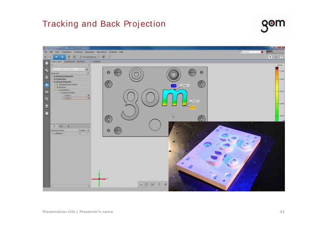
Tracking and Back Projection
TrackingEnables component alignment and positioningas well as transfer of the optimum virtualalignment to the real/physical world.
Applications in industry:∙ Component positioning for CNC machining ona machine tool
∙ Assembly analysis of molds and tools∙ Meisterbock & Cubing∙ Online positioning of a component in thenominal position or in an assembly
Back ProjectionEnables direct projection of elements ontoreal physical components in order tosupport machining and/or visualization.
Applications in industry:∙ Fast marking of workpiece∙ Marking for positioning in the millingmachine
∙ Verification of inspection results on thephysical workpiece
∙ Marking of machining areas
Text
Pict
ure
Text
Pict
ure
Text
Pict
ure
Text
Pict
ure
41Presentation title | Presenter's name
Tracking and Back Projection

Text
Pict
ure
Text
Pict
ure
Text
Pict
ure
Text
Pict
ure
42Presentation title | Presenter's name
Tracking and Back Projection

Text
Pict
ure
Text
Pict
ure
Text
Pict
ure
Text
Pict
ure
43Presentation title | Presenter's name
Certified Precision
GOM acceptance test of system accuracyaccording to VDI guideline 2634, part 3,with the title "Optical 3D-measuringsystems - Multiple view systems based onarea scanning"
Verification goes beyond the requirementsdescribed in the VDI/VDE guideline
Re-verification of the system accuracy ispossible at the customer site at any time

Text
Pict
ure
Text
Pict
ure
Text
Pict
ure
Text
Pict
ure
44Presentation title | Presenter's name
Calibration by User
ATOS is pre-calibrated and ready foroperation on delivery and thus requiresonly low maintenance
During the measuring process, GOMsystems automatically monitor theiraccuracy
Re-calibration by the user or automaticallyby using a robot

Text
Pict
ure
Text
Pict
ure
Text
Pict
ure
Text
Pict
ure
45Presentation title | Presenter's name
Flexible Sensor Concept
From small to big – stationary and mobile
... in the office ... in production
Flexibly scalable measurement fields
From small to big

Text
Pict
ure
Text
Pict
ure
Text
Pict
ure
Text
Pict
ure
46Presentation title | Presenter's name
Mobile – Stationary – Automated
Mobile measurement system Stationary system Automated measuring cell
One sensor head | modular design

Text
Pict
ure
Text
Pict
ure
Text
Pict
ure
Text
Pict
ure
4105 5108 5120 6130
47Presentation title | Presenter's name
ATOS ScanBox
Automated Full-field 3D Metrology
Standardized robotic measurement cell
Fully automated 3D digitizing and inspection
For different component sizes and applications

Text
Pict
ure
Text
Pict
ure
Text
Pict
ure
Text
Pict
ure
48Presentation title | Presenter's name
GOM Software
All 3D software solutions are part of GOM'sindustrial measuring systems.
Software for simple scanning tasks withATOS Core provides high-quality 3Dpolygon meshes in STL format
Numerous features for control of ATOSmeasuring systems with extensive shapeand dimension analysis
Inspection of 3D point clouds from whitelight scanners, laser scanners, CTs andother sources

Text
Pict
ure
Text
Pict
ure
Text
Pict
ure
Text
Pict
ure
49Presentation title | Presenter's name
Industries
Casting & Forging Injection Molding Blades
Tool & Mold Making Design Sheet Metal
ATOS is used in automotive, aviation, aerospace and consumer goods industries, theirsuppliers as well as research institutions and universities

Text
Pict
ure
Text
Pict
ure
Text
Pict
ure
Text
Pict
ure
50Presentation title | Presenters name
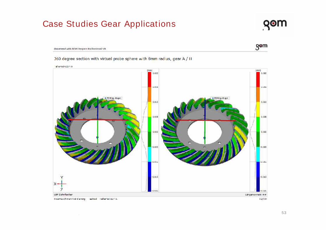
Case Studies Gear Applications

Text
Pict
ure
Text
Pict
ure
Text
Pict
ure
Text
Pict
ure
51Presentation title | Presenters name
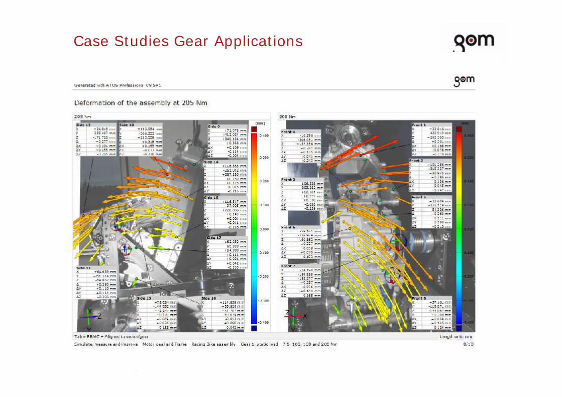
Case Studies Gear Applications

Text
Pict
ure
Text
Pict
ure
Text
Pict
ure
Text
Pict
ure
52Presentation title | Presenters name
Case Studies Gear Applications
Text
Pict
ure
Text
Pict
ure
Text
Pict
ure
Text
Pict
ure
53Presentation title | Presenters name
Case Studies Gear Applications

Text
Pict
ure
Text
Pict
ure
Text
Pict
ure
Text
Pict
ure
54Presentation title | Presenters name
Case Studies Gear Applications

Text
Pict
ure
Text
Pict
ure
Text
Pict
ure
Text
Pict
ure
55Presentation title | Presenters name
Case Studies Gear Applications
Text
Pict
ure
Text
Pict
ure
Text
Pict
ure
Text
Pict
ure
56Presentation title | Presenters name
Case Studies Gear Applications

Text
Pict
ure
Text
Pict
ure
Text
Pict
ure
Text
Pict
ure
57Presentation title | Presenters name
Case Studies Gear Applications

Text
Pict
ure
Text
Pict
ure
Text
Pict
ure
Text
Pict
ure
58Presentation title | Presenters name
Case Studies Gear Applications

Text
Pict
ure
Text
Pict
ure
Text
Pict
ure
Text
Pict
ure
Thanks for your timeFor further details contact
APM TechnologiesA-40 FIEE ComplexOkhla Phase-2, New Delhi-110020
sales@apmtechindia.com011-41631416www.gom.comwww.whitelightscanning.com