industrial catalogue - tnb.ca catalogue - web.pdf · area” classification system for ......
TRANSCRIPT

ww ww ww .. ll uu mm aa cc ee ll ll .. cc oo mm
I n d u s t r i a lC a t a l o g u e

CATALOG
Specia
l Colle
ctio
n


INDEX
Specia
l Colle
ctio
n
1. Hazardous Locations - C.E.C. Classi_cations ................ 06
2. IP Rating ........................................................................ 10
3. Products Table of Contents ............................................ 11
4. Exit Signs ........................................................................ 15
5. Remotes.......................................................................... 37
6. Battery Units .................................................................. 51
7. DC Systems, Options & Acessories .............................. 59

6
Hazardous Locations — C.E.C. Classifications
C.E.C. Code ChangesIn 1998, the Canadian ElectricalCode® (C.E.C.) adopted theInternational ElectrotechnicalCommission's (IEC) “Three ZoneArea” Classification System forClass I hazardous locations. TheZone System is an alternateclassification for Class Ihazardous locations and wasadopted to promoteharmonization with internationalstandards.
The Division System for Class I hazardous locations continues tobe used for existing facilities andis expected to remain in use atleast for the next few editions ofthe C.E.C. For this reason, thiscatalogue's certificationinformation for Class I hazardouslocations includes both the pre-1998 Division System and thenew I.E.C. Zone System.
The following pages provide anoverview of C.E.C. hazardouslocation classi_cations.
ClassesThe Canadian Electrical Code(C.E.C.), Part I, Section 18 -Hazardous Locations, identi_es threeclasses of hazardous locations:• Class I - Gas and VapourEnvironments
• Class II - Dust Environments• Class III - Fibers and FlyingsEnvironments
The 1998 revisions to the C.E.C.affect only Class I - Gas andVapour Environments.
Hazardous location is de_ned by theC.E.C. as premises, buildings or partsthereof in which there exists thehazard of _re or explosion due tohighly `ammable gases and/or`ammable, volatile liquid mixtures thatare manufactured, used or stored inother than the original containers.
This de_nition can also be extendedto include combustible dust andeasily ignitable _bers that are likelyto be present in suf_cient quantitiesto produce an explosive mixture.
Class I — Gas and Vapour Environments
Locations which are deemedhazardous due to the presence ofgases or vapours that are presentin the air in a suf_cient quantity toproduce explosive or ignitablemixtures.
Locations identi_ed as Class Irequire that enclosures andconnectors be explosion-proof.
Class I hazardous locations arefurther subdivided into :
• Divisions (pre-1998 version of theC.E.C.), or
• Zones (I.E.C. Classi_cation - 1998 C.E.C.)
The Division System may still beused for the maintenance and repairof existing facilities. All new
construction must use the I.E.C.Zone Classi_cation.
Divisions
• Division 1— a Class I locationwhere the hazardous atmosphereis expected to be present duringnormal operations on acontinuous, intermittent orperiodic basis.
• Division 2— a Class I location inwhich volatile `ammable liquids orgases are handled, processed orused but in which they wouldnormally be con_ned within closedcontainers or closed systems fromwhich they can escape only in theevent of an accidental rupture orbreakdown of the containers orsystems.

Class I — (continued)
Zones
• Zone 0—Class I locations inwhich explosive gas atmospheresare present continuously or arepresent for long periods.
• Zone 1 —Class I locations inwhich:i. explosive gas atmospheres arelikely to occur in normaloperation; or
ii. explosive gas atmospheres mayexist frequently because ofrepair or maintenanceoperations or because ofleakage; or
iii. the location is adjacent to aClass I, Zone 0 location, fromwhich explosive gasatmospheres could becommunicated.
• Zone 2—Class I locations inwhich:iv. explosive gas atmospheres arenot likely to occur in normaloperation and if they do occurthey will exist for a short timeonly; or
v. `ammable volatile liquids,`ammable gases or vapours arehandled, processed, or used,but in which liquids, gases orvapours are normally con_nedwithin closed containers orclosed systems from which theycan escape only as a result ofaccidental rupture orbreakdown of the containers orsystems or the abnormaloperation of the equipment bywhich the liquids or gases arehandled, processed or used; or
vi. explosive gas atmospheres arenormally prevented by adequateventilation by which may occuras a result of failure or abnormalope-ration of the ventilationsystem; or
vii. the location is adjacent to a ClassI, Zone 1 location from whichexplosive gas atmospheres couldbe communicated, unless suchcommunication is prevented byadequate positive-pressureventilation from a source of cleanair, and effective safeguardsagainst ventilation failure areprovided.
Area Classification — Divisions vs. Zones
Hazard Under
Continuous Hazard Intermittent Hazard Abnormal ConditionsZone 0 Zone 1 Zone 2
Division 1 Division 2
7
Hazardous Locations — C.E.C. Classifications
Class I Equipment
Electrical equipment that isapproved for use in Class IHazardous Location Areas (HLAs) isreferred to as explosion-proof or`ame-proof. This designation meansthat the equipment has beendesigned and manufactured toensure that it will not become asource of ignition when used in aClass I, Gas and Vapour HLA.
All explosion proof equipment isclearly identi_ed by either:
• a «Class I Location» marking(Division System); or
• a «Type of protection “d”» marking (IEC Zone System).
Gas Group Designations
Two systems of groupings for gasesare included in the 1998 C.E.C: thepre-1998 Division Gas Groupsconsisting of Groups A, B, C and D;and the IEC System consisting ofGroups IIA, IIB and IIC.Both systems are accepted by theC.E.C.
Haza
rdous Locatio
ns
8
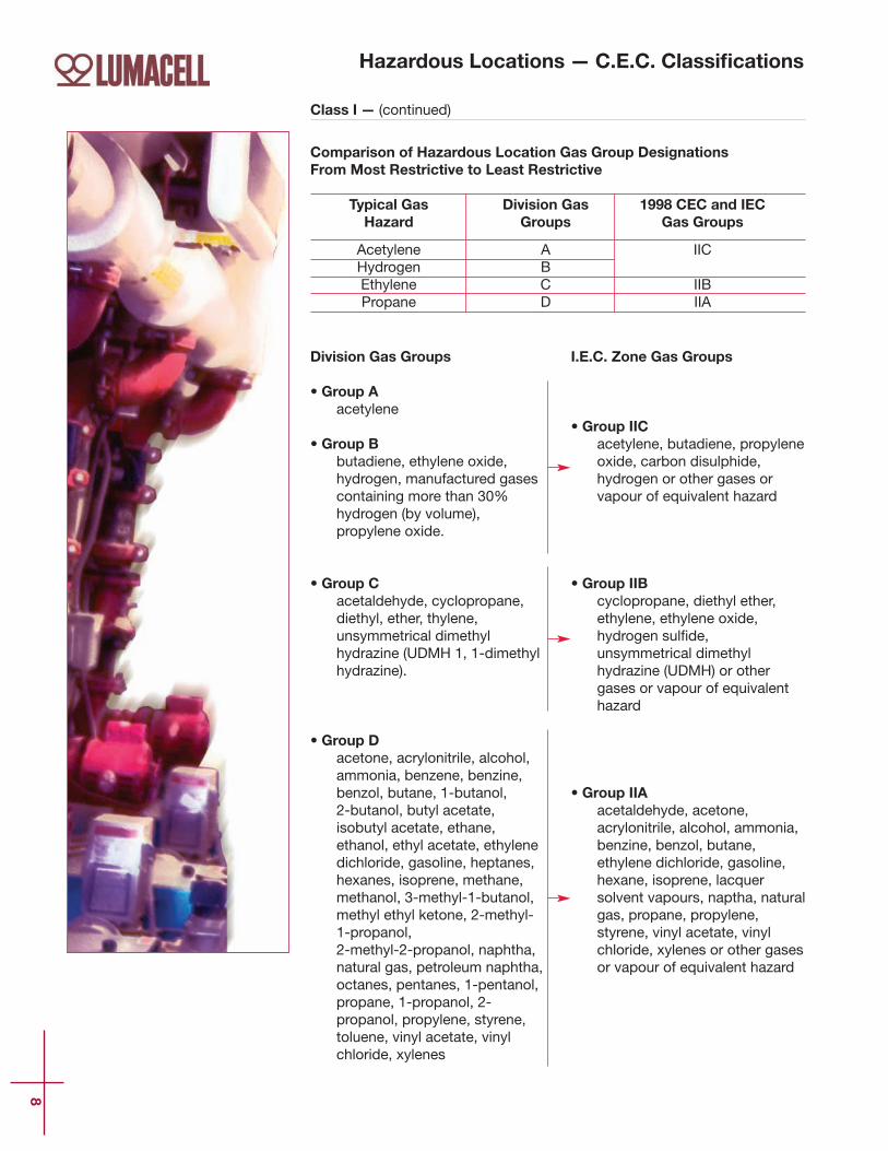
Division Gas Groups
• Group Aacetylene
• Group Bbutadiene, ethylene oxide, hydrogen, manufactured gasescontaining more than 30% hydrogen (by volume),propylene oxide.
• Group Cacetaldehyde, cyclopropane, diethyl, ether, thylene, unsymmetrical dimethylhydrazine (UDMH 1, 1-dimethylhydrazine).
• Group Dacetone, acrylonitrile, alcohol,ammonia, benzene, benzine, benzol, butane, 1-butanol, 2-butanol, butyl acetate, isobutyl acetate, ethane,ethanol, ethyl acetate, ethylenedichloride, gasoline, heptanes,hexanes, isoprene, methane,methanol, 3-methyl-1-butanol,methyl ethyl ketone, 2-methyl-1-propanol, 2-methyl-2-propanol, naphtha, natural gas, petroleum naphtha,octanes, pentanes, 1-pentanol,propane, 1-propanol, 2-propanol, propylene, styrene,toluene, vinyl acetate, vinylchloride, xylenes
I.E.C. Zone Gas Groups
• Group IICacetylene, butadiene, propyleneoxide, carbon disulphide, hydrogen or other gases orvapour of equivalent hazard
• Group IIBcyclopropane, diethyl ether, ethylene, ethylene oxide, hydrogen sul_de,unsymmetrical dimethylhydrazine (UDMH) or othergases or vapour of equivalenthazard
• Group IIAacetaldehyde, acetone, acrylonitrile, alcohol, ammonia,benzine, benzol, butane,ethylene dichloride, gasoline,hexane, isoprene, lacquersolvent vapours, naptha, naturalgas, propane, propylene,styrene, vinyl acetate, vinylchloride, xylenes or other gasesor vapour of equivalent hazard
Comparison of Hazardous Location Gas Group DesignationsFrom Most Restrictive to Least Restrictive
Typical Gas Division Gas 1998 CEC and IECHazard Groups Gas Groups
Acetylene A IICHydrogen BEthylene C IIBPropane D IIA
Class I — (continued)
Hazardous Locations — C.E.C. Classifications
9
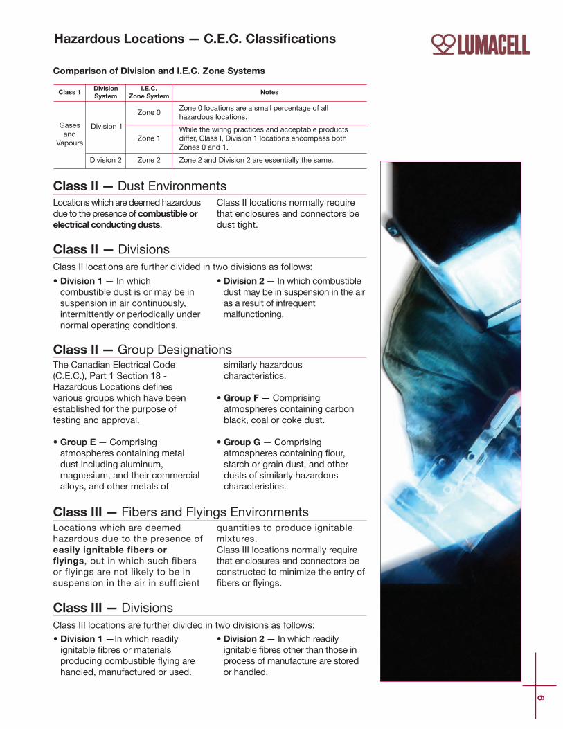
Class II — Dust EnvironmentsLocations which are deemed hazardousdue to the presence of combustible orelectrical conducting dusts.
Class II locations normally requirethat enclosures and connectors bedust tight.
Class III — Fibers and Flyings EnvironmentsLocations which are deemedhazardous due to the presence ofeasily ignitable fibers orflyings, but in which such fibersor flyings are not likely to be insuspension in the air in sufficient
quantities to produce ignitablemixtures.Class III locations normally requirethat enclosures and connectors beconstructed to minimize the entry of_bers or `yings.
Class II — DivisionsClass II locations are further divided in two divisions as follows:
• Division 1 — In whichcombustible dust is or may be insuspension in air continuously,intermittently or periodically undernormal operating conditions.
• Division 2— In which combustibledust may be in suspension in the airas a result of infrequentmalfunctioning.
Class III — DivisionsClass III locations are further divided in two divisions as follows:
• Division 1 —In which readilyignitable _bres or materialsproducing combustible `ying arehandled, manufactured or used.
• Division 2— In which readilyignitable _bres other than those inprocess of manufacture are storedor handled.
Class II — Group DesignationsThe Canadian Electrical Code(C.E.C.), Part 1 Section 18 -Hazardous Locations de_nesvarious groups which have beenestablished for the purpose oftesting and approval.
• Group E—Comprisingatmospheres containing metaldust including aluminum,magnesium, and their commercialalloys, and other metals of
similarly hazardouscharacteristics.
• Group F—Comprisingatmospheres containing carbonblack, coal or coke dust.
• Group G—Comprisingatmospheres containing `our,starch or grain dust, and otherdusts of similarly hazardouscharacteristics.
Class 1DivisionSystem
I.E.C.Zone System
Notes
Gasesand
Vapours
Division 1
Zone 0Zone 0 locations are a small percentage of allhazardous locations.
Zone 1While the wiring practices and acceptable productsdiffer, Class I, Division 1 locations encompass bothZones 0 and 1.
Division 2 Zone 2 Zone 2 and Division 2 are essentially the same.
Comparison of Division and I.E.C. Zone Systems
Hazardous Locations — C.E.C. Classifications

10
Although IP is mainly a Europeanrating system, it is referred to
more and more in North America,especially for lighting _xturesneeding a wet location label.
The _rst number of an IP ratingrepresents the degree of protection
against penetration of solids and thesecond number, the degree ofprotection against penetration ofwater. So, for example, a wallsconce that is rated IP65 iscompletely protected againstpenetration of dust particles andagainst jets of water.
IP R
atin
g
SECOND IDENTIFICATIONNUMBER
Degree of protection againstpenetration of water.
0 Not Protected
1 Protected against verticalfall of water drops
2 Protected against the fall ofwater at a maximum angleof 15”
3 Protected against rain
4 Protected against splashes
5 Protected against jets ofwater
6 Protected against waves
7 Protected against theeffects of immersion
8 Protected against theeffects of prolongedimmersion
Degree of protection
FIRST IDENTIFICATION NUMBER
Degree of protection againstpenetration of solids.
0 Not Protected
1 Protected againstpenetration of solids largerthan 2”
2 Protected againstpenetration of solids largerthan 1/2”
3 Protected againstpenetration of solids largerthan 3/32”
4 Protected againstpenetration of solids largerthan 1/32”
5 Protected againstpenetration of dust
6 Completely protectedagainst penetration of dust

CATALOGP
roducts
12
P r o du c t s
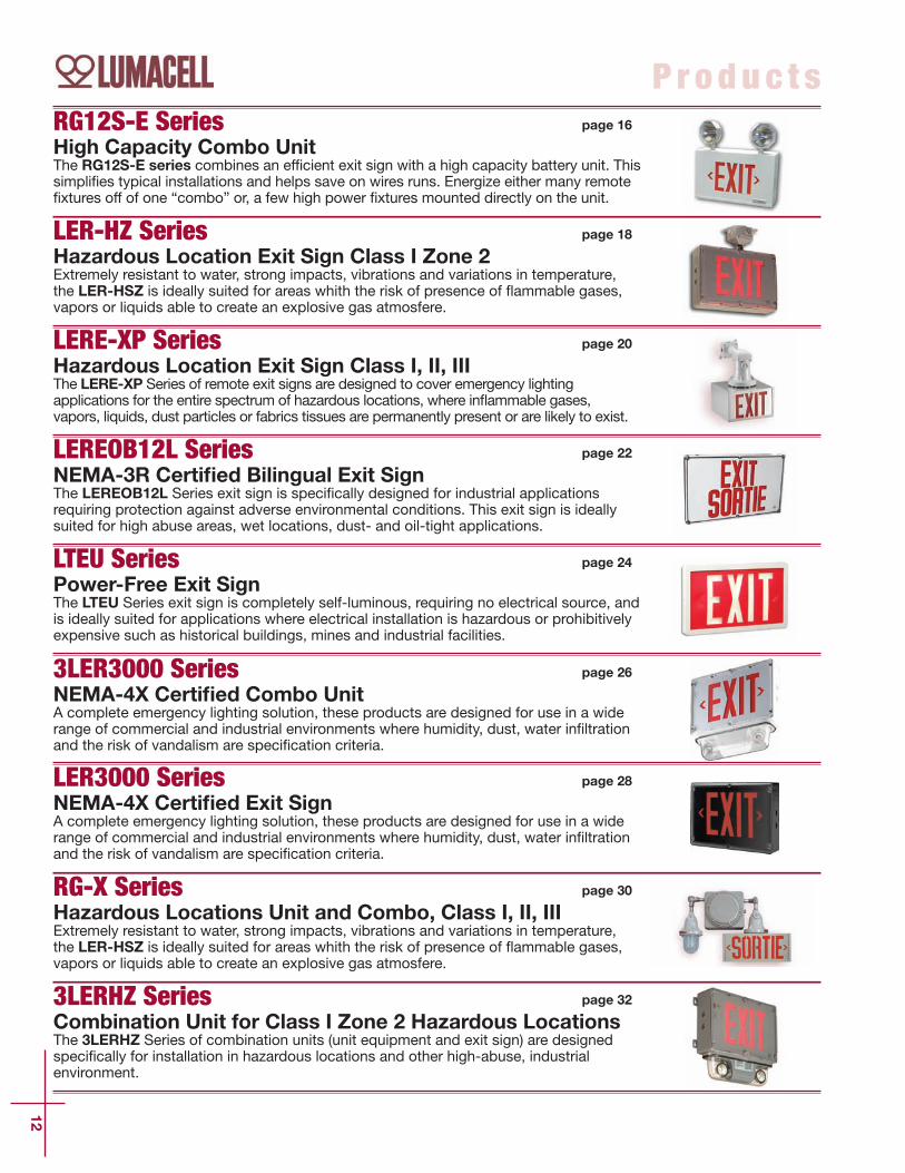
LER-HZ SeriesHazardous Location Exit Sign Class I Zone 2Extremely resistant to water, strong impacts, vibrations and variations in temperature,the LER-HSZ is ideally suited for areas whith the risk of presence of `ammable gases,vapors or liquids able to create an explosive gas atmosfere.
page 18
3LER3000 SeriesNEMA-4X Certified Combo UnitA complete emergency lighting solution, these products are designed for use in a widerange of commercial and industrial environments where humidity, dust, water in_ltrationand the risk of vandalism are speci_cation criteria.
page 26
LEREOB12L SeriesNEMA-3R Certified Bilingual Exit SignThe LEREOB12L Series exit sign is speci_cally designed for industrial applicationsrequiring protection against adverse environmental conditions. This exit sign is ideallysuited for high abuse areas, wet locations, dust- and oil-tight applications.
page 22
LERE-XP SeriesHazardous Location Exit Sign Class I, II, IIIThe LERE-XP Series of remote exit signs are designed to cover emergency lightingapplications for the entire spectrum of hazardous locations, where in`ammable gases,vapors, liquids, dust particles or fabrics tissues are permanently present or are likely to exist.
page 20
LTEU SeriesPower-Free Exit SignThe LTEU Series exit sign is completely self-luminous, requiring no electrical source, andis ideally suited for applications where electrical installation is hazardous or prohibitivelyexpensive such as historical buildings, mines and industrial facilities.
page 24
LER3000 SeriesNEMA-4X Certified Exit SignA complete emergency lighting solution, these products are designed for use in a widerange of commercial and industrial environments where humidity, dust, water in_ltrationand the risk of vandalism are speci_cation criteria.
page 28
RG12S-E SeriesHigh Capacity Combo UnitThe RG12S-E series combines an ef_cient exit sign with a high capacity battery unit. Thissimpli_es typical installations and helps save on wires runs. Energize either many remote_xtures off of one “combo” or, a few high power _xtures mounted directly on the unit.
page 16
RG-X SeriesHazardous Locations Unit and Combo, Class I, II, IIIExtremely resistant to water, strong impacts, vibrations and variations in temperature,the LER-HSZ is ideally suited for areas whith the risk of presence of `ammable gases,vapors or liquids able to create an explosive gas atmosfere.
page 30
3LERHZ SeriesCombination Unit for Class I Zone 2 Hazardous LocationsThe 3LERHZ Series of combination units (unit equipment and exit sign) are designedspeci_cally for installation in hazardous locations and other high-abuse, industrialenvironment.
page 32

MQM-NX SeriesRemote Fixture - Water Proof NEMA-4X Series
A complete emergency lighting solution, these products are designed for use in a widerange of commercial and industrial environments where humidity, dust, water in_ltration
and the risk of vandalism are speci_cation criteria.
13
P r o du c t s
RS-WP SeriesRemote Fixture - Water Proof Series
PAR 36, surface-mounted industrial remote _xtures. Available in single, double or triplehead _xtures. Durable thermoplastic construction suitable for industrial or high abuse
areas.
page 44
RS-WPRB SeriesWater Proof Series
Sealed beam, PAR 36, surface-mounted, rubber coated industrial remote _xture.
page 45
RS10/RS20/RS30T SeriesSurface Mounted Series
PAR36, surface-mounted, large remote _xtures. Single, double or triple head. Positiveaim swivel. Available in factory white (standard) and black.
page 46
MT-W4T SeriesWater Proof Series
NEMA-4X listed, surface-mounted, square industrial remote _xture. Available withtungsten or quartz lamps in single or double head con_gurations. Gray _berglass base
and clear polycarbonate lens.
page 45
MQM-HZ SeriesRemote Fixture for Hazardous Locations Class I Zone 2
The MQM-HZ Series of remote _xtures has been designed speci_cally forinstallation in hazardous locations and other and high-abuse, industrial
environments.
page 36
page 38
Saf-T-Ray SeriesVandal Resistant Wall Mount Remote Head
The Saf-T-RayTM wall sconce unit was designed and engineered with durability andsophistication in mind. Its low-pro_le aesthetic design will provide an attractive
alternative to the typical two-headed standard emergency lighting unit.
page 40
RS10XP SeriesRemote Lighting Fixtures for Hazardous Location Class I, II, IIIThe RS10XP Series of remote emergency lighting heads is designed to cover emergency lightingapplications for the entire spectrum of hazardous locations, where in`ammable gases, vapors,
liquids, dust particles or fabrics, tissues are permanently present or are likely to exist.
page 42
RSQB/RSQBD/RSQB2 SeriesSurface Mounted Series
Cubic, vandal-resistant surface-mounted _xture. Single, double or twin cube with centerbody. Available in factory white (standard) and black with frosted polycarbonate cube.
page 47

Zone Sensing VSR SeriesThe VSR (Voltage Sensing Relay) option activates all of the emergencylighting if only one, multiple or all zones become de-energized througheither a power failure or lighting circuit breaker tripping.
page 68
RG-HZ SeriesBattery Unit for Hazardous Locations Class I Zone 2The RG-HZ Series of battery units are designed speci_cally for installation in hazardouslocations and other high-abuse, industrial environments. Extremely resistant to water,high impacts, vibrations and variations in temperature.
RG-NX SeriesNEMA-4X Certified Battery UnitA complete emergency lighting solution, these products are designed for use in a widerange of commercial and industrial environments where humidity, dust, water in_ltrationand the risk of vandalism are speci_cation criteria.
14
P r o du c t s
page 52
Nexus SystemThe NEXUS project started in Australia. Following many successful installations “downunder”,Thomas & Betts decided to adapt NEXUS to North American norms andspeci_cations, as this system is a truly useful maintenance tool for property owners andmanagers.
page 70
RGS-DT SeriesNEMA-12 Cassified, 6, 12 and 24 Volts Battery UnitsThe RGS-DT Series battery units are specifically designed for use in industrial facilitieswhere equipment is exposed to dust, water, oil or corrosive substances.
page 50
LUMA Source Series120 VDC Central Single SourceIn an existing or new installation where exit signs and emergency lightingmay be supplied by a single 120VDC source using a common negativewire and a switched positive.
page 62
DC Central SystemsFully Automatic ChargerLumacell’s Central DC Systems are utilized where a large number of remote heads orstandard 120 Volt incandescent _xtures. The systems offer the advantage of a centrallocation for maintenance with full supervision of all operating functions.
page 64
page 54
IPLTM SeriesIP65 Linear Fluorescent FixtureThe IPLTM Series of `uorescent _xtures by Lumacell are offered as normally on standardlinear `uorescent _xtures. When used with one of our `uorescent inverters, the IPLTM isconverted to a self-powered emergency lighting unit.
page 56
CATALOG
Exit S
igns

16
RG12S - E S e r i e s
Supply and install a unit thatcombines an illuminated LED exitsign with an emergency light batteryunit. The housing and faceplate shallbe constructed of steel. Thefaceplate shall come standard withknock out chevrons. The light sourcefor the exit sign shall be LED. TheLED lamps shall provide illuminationin normal and emergency operation.Red LEDs shall be of ALINGAP*technology. The charger board, thebattery and the LEDs shall becontained in a single housing. Adiffuser optimized for LEDs shall bemounted behind the legend toprovide the 6” high by 3/4” strokeletters with even illumination.
The unit shall include a test switchand high charge pilot light. Theequipment shall be designed tofurnish exit illumination from thenormal AC source. When a powerfailure occurs, the exit sign alongwith the emergency heads shallilluminate for a minimum of 30minutes. The power available foremergency lights shall be at least110 watts or as otherwise speci_ed.
The heads shall require no tools toaim and shall be as speci_ed. Theexit sign shall be CSA-C860-07approved. The equipment shall be LumacellModel – RG12S_________________.
High Capacity Combo UnitUp to 360 watts of Remote Capacity
16 1/8”[41.0cm]
5 1/2”[13.8cm] 5 1/2”
[13.8cm]
13 7/8”[35.3cm]
16 1/8”[41.0cm]
10 1/4”[26.0cm]
B CABINET(110W and 144W)
Features• High quality steel enclosure with corrosion resistant undercoating
• Fully C860 approved “Exit” legend illuminated with ALINGAP LEDs
• Available in 12 volts, 110, 144, 250 and 360 watts
• Standard 120/347Vac input
• Optional Auto-test charger (available with 110 watts only)
• Long life, maintenance free lead acid battery
• Sealed dust-proof transfer relay
• Solid state pulse type charger standard
Dimensions
The RG12S-E seriescombines an efficient exitsign with a high capacity
battery unit. This simplifiestypical installations and
helps save on wires runs.Energize either many
remote fixtures off of one“combo” or, a few highpower fixtures mounted
directly on the unit
Typical Specification
16 1/8”[41.1cm]
5 3/8”[13.8cm]
5 1/2”[13.8cm]
13 7/8”[35.4cm]10 1/4”
[26.1cm]
23 1/8”[58.8cm]
C CABINET(250W and 360W)

17
RG12S-E
Serie
s
*ALINGAP (AlInGaP): Aluminum, Indium, Gallium and Phosphorus. ALINGAP LEDoffers a higher light efficacy, with the Lumen/Watt ratio 300% to 500% higher thanthe traditional GaAs LED. AlInGaP Exit signs are designed for 10 years+ of CSA/UL photometric compliance.AlInGaP LEDs show an annual light loss rate 10 times lowers than the average lightloss of standard GaAs LEDs.
RG12S110 E 2 MT9W B ZC AT
Series Lettering # of Heads Head Style and Wattage Colour* Voltage Options
RG12S110 =12V-110watts
E =EXIT
Blank =no heads
MT9W =mini tungsten, 12V - 9watt, wedge base
Blank =factory white
Blank =120/347VAC
AT =autotest (110w only)
RG12S144 =12V-144watts
1 =one head
MT18W = mini tungsten, 12V - 18watt, wedge base
B =Black
ZC =277VAC
Blank =No options
RG12S250 =12V-250watts
2 =two heads
MQ8W =mini halogen, 12V - 8watt, quartz bi-pin
* Other coloursavailble ondemand.
Consult yoursales
representative.
RG12S360 =12V-360watts
3 =three heads
MQ12W =mini halogen,12V -12watt, quartz bi-pin
B Cabinet for110w or
144w and CCabinet for250w or360w
MM12W =mini halogen,12V - 12watt, MR16
MM20W =mini halogen, 12V - 20watt, MR16
LH9W =large tungsten ,12V - 9watt, wedge base
LH18W =large tungsten, 12V - 18watt, wedge base
LH25W =large tungsten,12V - 25watt, DCB
LQ12W =large halogen,12V - 12watt, quartz bi-pin
LQ20W =large halogen, 12V - 20watt, quartz bi-pin
LQ55W =large halogen,12V - 55watt, quartz bi-pin
SB12W =large tungsten,12V - 9watt, sealed beam
SB18W =large tungsten,12V - 18watt, sealed beam
SB25W =large tungsten, 12V - 25watt, sealed beam
SQ8W =large halogen,12V - 8watt, quartz sealed beam
SQ12W =large halogen,12V - 12watt, quartz sealed beam
D12W =Deco head DR130, 12V - 12watt, MR16
D20W =Deco head DR130, 12V - 20watt, MR16
D35W =Deco head DR130, 12V - 35watt, MR16
D50W =Deco head DR130, 12V - 50watt, MR16
Ordering InformationEXAMPLE:

18
L ER -H Z Se r i e s
Supply and install Lumacell LER-HZSeries LED exit signs. The equipmentshall operate with universal two-wireAC input voltage from 120Vac to347Vac at less than 3 watts anduniversal two-wire DC input voltagefrom 6Vdc to 48Vdc at less than 2watts for single and double facesigns. Designed speci_cally for hostileenvironments, the equipment frameshall be of industrial grade highimpact thermoplastic with a gasketaround lenses and canopy. Thefaceplate(s) shall be constructed ofheavy-duty vandal-resistantpolycarbonate and feature an evenilluminated legend. The light sourceshall be light emitting diodes (LED).Red LED technology shall beALINGAP. An LED-sensitive diffusershall be mounted behind the legendto provide the 6” high by 3/4” strokeletters with even illumination.
The equipment shall be certi_ed forHazardous Locations: Class I Division2 Groups A, B, C and D with a
temperature code T6 (Maximum85ºC). The equipment shall bedesigned speci_cally for high abuseareas, wet location, and cold weather(-20°C) applications. The self-poweredmodel shall stay illuminated duringemergency operation for at least 90minutes upon AC failure and shallinclude a magnetic test switch andself-testing / self-diagnostic functions.
The equipment shall automaticallyself test for 5 minutes every 30 days,30 minutes every 60 days and 90minutes annually. A “Servicerequired” lamp shall be located nearthe test switch and `ash when a faultis detected. A two-LED diagnosticdisplay shall be located inside theequipment and shall identify theeventual source of failure (battery,charger circuitry, or LED lamps).
The exit sign shall be CSA-C860-07approved.The exit sign shall be LumacellModel – _______________________.
HAZARDOUS LOCATION LED EXIT SIGNClass I, Zone 2 - compliant LED exit sign
Features• Certified Class I Division2, Groups A, B, C and D as per CSA C22.2No.137-M1981, Class I, Zone 2, Groups IIC, IIB and IIA
• Temperature Code: T6 (maximum 85ºC as per Canadian ElectricalCode, Part I and CSA C22.2 No.137-M1981)
• Certified CSA C860-07• Suitable for cold-weather: -20ºC (self-powered model, “CW” option)and -40ºC (AC-only and AC-DC models)
• Input voltages: 120 to 347Vac universal AC-input; 6 to 48Vdc universalDC-input
• High impact thermoplastic frame, with built-in gasket to preventwater infiltration
• Sealed faceplate of heavy-duty, vandal-resistant polycarbonate• Tamper-resistant, hermetically sealed magnetic test switch• Self-test / self-diagnostic circuitry is standard on self-poweredmodels
• Sealed, maintenance-free, Nickel-Cadmium batteries• Batteries recharge as per CSA requirements and provide 90 minutesof emergency operation
• Long-life, energy-efficient ALINGAP red LED light source• Energy efficient – consumes less than 3 watts in AC or DC mode
The LER-HZ Series of Exitsigns has been designed
specifically for installation inhazardous locations and
other high-abuse, industrialenvironments. Extremelyresistant to water, highimpacts, vibrations and
variations in temperature,the LER-HZ Series is ideallysuited for areas with the risk
of presence of flammablegases, vapors or liquids
able to create an explosivegas atmosphere.
Typical Specification

19
LER-H
Z S
erie
s
Dimensions
Power ConsumptionModel AC Specs DC Specs
AC/DC redAC/DC greenSelf-powered redSelf-powered green
120 to 347Vac120 to 347Vac120 to 347Vac120 to 347Vac
Less than 3WLess than 3WLess than 3WLess than 3W
Ordering information
6 to 48Vdc6 to 48VdcNiCad batteryNiCad battery
Less than 2WLess than 2WMin. 90 minutesMin. 90 minutes
9 1/8”(23.2 cm)
13 1/4” (33.6 cm)
13 1/2” (34.2 cm)
4 3/8”(11 cm)
3 1/2” (8.9 cm)
2 1/4” (5.7 cm)
LERHZ 500 SG SPD GN
Series Faces/Mounting Colour Voltage Options
LERHZ =EXIT
hazardouslocation
500 =single face, ceiling or wall
mount600 =
double face, ceiling mount only
SG =grey/grey
Blank =universal120-347Vac, 6-48Vdc
SPD =120-347Vac, self-powered c/w diagnostic
(non audible)VACDC2 =
120Vac, 120Vdc 2 wire (AC only)NEX =
Nexus System Interface*
*Nexus option with self-powered models only
Blank =no optionGN =
green lettersCW =
cold weather*
*(-20ºC for self-powered, -40ºCfor AC/DC)
EXAMPLE:

RSTP Se r i e sTransferPanels
LERE-XP SeriesHazardous Location
Exit Signs
20
CSA certified for use in hazardous locationsClass I, Zone 1, Groups IIC, IIB and IIA for Severity Code 1 productsClass I, Zone 1, Groups IIB and IIA for Severity Code 2 productsClass I, Zone 2, Groups IIC, IIB and IIA for Severity Code 3 products
FeaturesREW-XP Series Exit Signs• CSA Certified for use in hazardous locations:
• Class I, Divisions 1 and 2, Groups A, B, C, D• Class II, Divisions 1 and 2, Groups E, F, G• Class III, Divisions 1 and 2
• Die-cast aluminum body with gray epoxy powder coat finish• Exit housing and faceplate made of industrial-grade 14-gauge steeland finished in gray enamel
• Faceplate features universal knockout chevrons • Two-wire input circuit for both AC and DC inputs• Available in 6, 12, 24 and 120Vac/dc• LED lamp with ALINGAP LEDs; consumes less than 5 Watts in ACand DC mode
• New, easy-to-build catalogue number based on the Lumacell SeverityCodes
• CSA certified, meets or exceeds C860-07 requirements
RSTP Series Transfer Panel• Available with hazardous location housing (Class I, II and III) orNEMA-1 housing (for use outside the hazardous location area)
• Standard AC input: 120Vac, optional 277Vac, 347Vac; standard DCinput: 6, 12 or 24Vdc
• Two-wire output with permanently present AC/DC low voltage • Output power: 25W, can drive up to five (5) units of the LERE-XPremote exit series
• Also available as self-powered exit sign, battery unit and combo unit;see RG-X catalogue sheet
LERE-XP Series Remote Exit Sign:Supply and install the LumacellLERE-XP Series remote exit sign.The exit housing shall be industrialgrade 14-gauge steel and _nished ingray enamel. The faceplate will beconstructed of heavy-duty14-gauge steel and feature universalknockout chevrons and the red lettersshall not be less than 6” (150 mm) inheight with a 3/4” (19 mm) stroke.The sign shall come complete with a____Volt LED lamp, and function fromone voltage source only, in AC and DCcurrent. The LED Lamp shall useALINGAP LEDs and shall consume lessthan 5 watts in either AC or DC current. The exit sign shall be CSA-C860-07approved.
The exit sign shall be suitable forClass ___, Division ___, Group ____. The exit sign shall be LumacellModel - ________________________.RSTP Series Transfer Panel:Supply and install the LumacellRSTP Series transfer panel forhazardous location remote exitsigns. The unit shall have twovoltage inputs: ____ Vac and ____Vdc and shall be able to maintainan output of ____Volts 25 watts forthe permanent supply of a total offour remote LED exit signs. The transfer panel shall be suitablefor Class ___, Division ___,Group ___or for a NEMA 1 environment. The unit shall be Lumacell Model -__________________.
The LERE-XP Series ofremote exit signs are
designed to coveremergency lighting
applications for the entirespectrum of hazardous
locations, whereinflammable gases, vapors,
liquids, dust particles orfabrics tissues are
permanently present or arelikely to exist. The LERE-XP
remote exit signs can beconnected to the RSTP
transfer panel (see below),the RG-X Series of batteryequipment, or the Lumacell
DC system.
Typical Specification

LERE-X
P S
eries &RSTP
Series
21
Dimensions
Ordering Information
DOUBLE PENDANT MOUNT
SEVERITY S3, S4
SEVERITY S1, S2
CEILING MOUNT PENDANT MOUNTNo Severity Rating
Severity Class S1,
S2, S3 and S4
Before ordering, identify the environment of your application: Class___, Division___,Group___. Refer to the following chart for the Severity Code to use in your cataloguenumber:___________________ .
S1 S2S3S4
SeverityCode
Cl. I, Div. 1, Gr. A, BCl. I, Div. 1, Gr. C, D
CI. I, Div. 2, Gr. A, B, C, D Cl. II, Div. 1 & 2, Gr. E, F, G
Cl. III, Div. 1 & 2
EnvironmentFor temperature information, pleaselook at the table below:
S4
T3C (EGF)
Max 160°C
Certification Guide for LERE-XP Series Exit Signs (40°C ambient)
Severity Code
Temperature Code
CSA/UL rating
S1
T6
Max 85°C
S2
T6
Max 85°C
S3
T3C
Max 160°C
Transfer Panel
LERE1X -L12 S1 W
Series Voltage Lamp Type Severity Code Mounting
LERE1X =exit single face C860 LED
LERE2X =exit double face C860 LED
-L6 = 6 volts-L12 = 12 volts-L24 = 24 volts-L120 = 120 volts
Blank = L.E.D. lessthan 5 watts
S1 = see chartS2 = see chartS3 = see chartS4 = see chart
C = ceilingP = pendantW = wall
EXAMPLE:
RSTP 120 12 25
Series A.C. Voltage D.C. Voltage Load Wattage Housing
RSTP = transfer panel 120 = 120Vac347 = 347Vac
6 = 6 volts 12 = 12 volts24 = 24 volts
25 = 25 watts Blank = NEMA 1XP = hazardous
location
EXAMPLE:
12 3/8”[31.4cm]
303/8”[77.1cm]
241 /4 ”
[61.
5cm
]
71 /8 ”[1
8.1c
m]
147 /8 ”
[37.
7cm
]
123/8” [31.4cm]
51/4”[13.3cm]
173 /8 ”
[44.
2cm
]
83/8” [21.3cm]
81 /2 ”[2
1.5c
m]
10” [25.4cm]
9” [22.9cm]
101 /4 ”
[26.
0cm
]
91 /4 ” [2
3.5c
m]
8” [2
0.3c
m]
41 /8 ”[1
0.4c
m]
147 /8 ”
[37.
7cm
] 33” [
83.9
cm]
6”
[15.
3cm
]
6”
[15.
3cm
]6”
[1
5.3c
m]
6”
[15.
3cm
]
6”
[15.
3cm
]
95 /8 ” [2
4.5c
m]
12 3/8”[31.4cm] 303/4”
[78.0cm]
193 /4 ”
[50.
50cm
]
31 /8 ”[7
.8cm
]10
7 /8 ” [2
7.5c
m]
123/8” [31.4cm]
121/4” [5.7cm]
133/8” [34.1cm]123/8” [31.4cm]
4” [10.1cm]
107 /8 ”
[27.
5cm
]
31 /2 ” [9
.0cm
]
33 /8 ” [8
.4cm
]
121 /4 ”
[31.
2cm
]
281 /2 ”
[72.
3cm
]
107 /8 ”
[27.
5cm
]111 /4 ”
[28.
7cm
]

22
L EREOB12 L Se r i e s
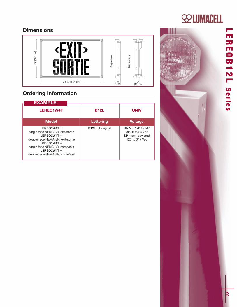
Features• Certified NEMA-3R • Gasketed fiberglass housing designed specifically for industrialapplications
• Gray finish is standard• Sealed, vandal-resistant polycarbonate faceplate• Long-life, even illumination of “EXIT SORTIE” legend provided byenergy efficient, ALINGAP technology LED light source consumingless than 3 watts per face (standard AC/DC model)
• Wall or ceiling mounting; wall or ceiling brackets available for easyinstallation
• Normal AC and emergency DC operation – 120 to 347 volts AC input;6 to 24 DC input
• CSA certified, meets or exceeds C860-01 and NRCAN/C860-01requirements
• The self-powered version is also CSA C22.2 No. 141 certified
Typical Specifications
Power Consumption
ModelAC/DC red
Self-powered red
AC Specs*120 to 347 Vac Less than 3W
120 to 347 Vac Less than 6W
Note: The values of power consumption are for single-face model (max. 6W / bilingual legend).
Note: For the certi_cation guide and temperature codes, please refer toboth pages from the LERE-XP Series of exit signs and the RS10XP Seriesof remote lighting _xtures or consult factory.
The LEREOB12L Series exitsign is specifically designedfor industrial applications
requiring protection againstadverse environmental
conditions. This exit sign isideally suited for high abuse
areas and wet locationsapplications.
NEMA-3R Certified Bilingual Exit Sign
Supply and install LumacellLEREOB12L Bilingual Led exit sign.The equipment shall operate withuniversal two-wire AC input voltagefrom 120 Vac to 347 Vac a less than 3 Watts per face and universal two-wire DC input voltage from 6 Vdc to24 Vdc at less than 3 Watts per face.The housing shall be of gray_berglass, gasketed, speciallydesigned for industrial environment.The sealed front cover shall beconstructed of heavy-duty vandal-resistant transparent polycarbonateof 4mm thickness and shall be bentaround the back box for increasedrigidity. The front cover will featurean even illuminated legend with the
text ”EXIT” and “SORTIE” positionedone on top of the other. The lightsource shall be the new ALINGAPtechnology red LED. The equipmentshall be suitable for wall or ceilingmount and be designed speci_callyfor high abuse areas, wet locations,dust and oil-tight applications. Theequipment in a self-poweredcon_guration shall stay illuminatedduring emergency operation for atleast 60 minutes upon AC failure.
The equipment shall be NEMA-3R,C-860 and NRCan approved.
The equipment shall be LumacellModel - _______________________ .
DC Specs*6 to 24 Vdc Less than 3W
NiCad battery Min. 60 min.
23
LEREOB12L S
erie
s
Ordering Information
LEREO1W4T B12L UNIV
Model Lettering Voltage
LEREO1W4T =single face NEMA-3R, exit/sortie
LEREO2W4T =double face NEMA-3R, exit/sortie
LSRSO1W4T =single face NEMA-3R, sortie/exit
LSRSO2W4T =double face NEMA-3R, sortie/exit
B12L = bilingual UNIV = 120 to 347Vac, 6 to 24 VdcSP = self-powered120 to 347 Vac
EXAMPLE:
po
po
po po
24 1/8“ [61.4 cm]
15“ [38.1 cm
]
Simple face
Double face
4”[10.2 cm]
2”[5.1cm]
Dimensions

24
LT EU Se r i e s
Features• Illumination provided by borosilicate glass tubes, internally coatedwith zinc sulphide phosphor and filled with tritium gas
• Minimum brightness at time of manufacture is 0.132 foot-lambert(0.452 cd/m2)
• Decorative, slim-line heavy-duty ABS housing
• Rugged, impact-resistant polycarbonate face
• Spark free construction
• Simple installation – universal direction capability, comes completewith universal mounting hardware
• Stands up to extreme temperatures in outdoor or indoor applications
• Standard 12-year life expectancy. 15- or 20-year life expectanciesavailable as an option
Typical Specification
Power Free Exit SignSelf-luminous, independent operation exit sign
Dimensions
Wire Guards
The LTEU Series exit sign iscompletely self-luminous,
requiring no electricalsource, and is ideally suited
for applications whereelectrical installation is
hazardous or prohibitivelyexpensive such as historical
buildings, mines andindustrial facilities. TheLTEU Series can also beused for all classes and
divisions of explosion-proofenvironments such as oilrefineries, pulp and papermills, chemical plants and
grain elevators.
Supply and install Lumacell LTEUSeries self-luminous exit signs.
The exit shall be constructed of athermoplastic housing and becorrosion proof. The sealed housingwill incorporate no loose orremovable parts allowing for easyinstallation. The standard expectedlife shall be 12 years with a minimumguaranteed life of 10 years. The
standard mounting brackets will allowfor either end/ceiling or wall mount.Standard signs shall be supplied withred face, grey frame and white lettersthat are 6” high by 3/4” stroke. Theinitial average minimum brightnessshall be .132 foot-lambert(0.452cd/m2)
The Exit shall be Lumacell Model -________________________________.
460.0079 Wall Mount460.0027 End Mount460.0028 Ceiling Mount

25
Ordering Information
LTEU 1
Series Faceplates/Mounting Housing Colour Life Years Options
LTEU = exitLTB3LE/S = exit/sortiLTB3LS/E = sortie/exit
1 = single face,universal mount2 = double face,universal mount
Blank = greyWH = whiteB = black
Blank = 12 years15 = 15 years20 = 20 years
SW = special wordingGN = green background Contactfactory for disposal procedures.
EXAMPLE:
LTEU S
erie
s

26
Combo Unit NEMA-4X Certified Combo Unit
FeaturesStandard• NEMA-4X Certified for wall or ceiling mount
• High efficiency MR16 halogen lamps up to 12V, 12W or 12V, 5W whiteLED, MR16 emergency lights
• Uniform Alingap technology LED illuminated legend
• Comes standard with non-audible advanced diagnostic chargerboard, 10 minute time delay and lamp disconnect
• Audible warning and time delay functions can be enabled or disabled
• Micro-controller diagnostic system tests, detects and indicatesbattery, charger circuitry, LEDs or MR16 lamp failures
• Sealed, maintenance-free nickel cadmium battery
• Non-intrusive magnetic test switch
• Choice of grey, factory white or black housing and face
• NSF Certified for food processing plants
• CSA Certified, meets or exceeds C860-07 requirements
• CSA C22.2 No. 141 Certified
Optional• Double face
• Cold weather (-40°C; 6Volt Unit)
• No heads (for more remote capacity)
• Fire alarm activated flasher
• Flasher/buzzer (AC power failure)
• Flasher (AC power failure)
Dimensions
NEMA-4X
DO
UBL
E FA
CE
SIN
GLE
FAC
E
13 1/4˝(33.6cm)
9 1/4˝(23.4cm)
12 5/8˝(32.1cm)
3 7/8˝(9.9cm)
3 1/2˝(8.7cm)
3 L ER3000 Se r i e s
Innovative, field-adjustablelamp head assembly
Choice of MR16 halogenlamps up to 12V, 12W
or high-efficiency, 5-Watt,MR16 LED lamps
Long life, energy efficientALINGAP technology
red LED illuminated EXITlegend
Can be wall or ceilingmounted
Double face availableSuitable for cold weatherapplications -40˚C (CW
option — available in 6V only)
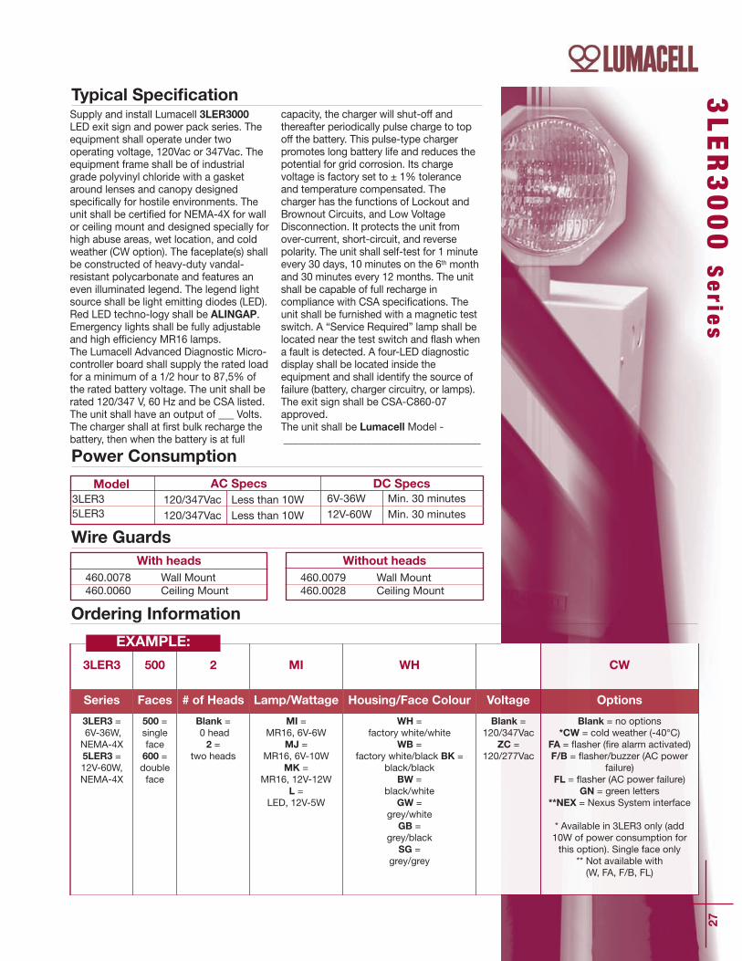
DC Specs6V-36W Min. 30 minutes12V-60W Min. 30 minutes
Model3LER35LER3
AC Specs120/347Vac Less than 10W120/347Vac Less than 10W
27
Power Consumption
Typical Specification
With heads
Wire GuardsWithout heads
460.0079 Wall Mount460.0028 Ceiling Mount
460.0078 Wall Mount460.0060 Ceiling Mount
3LER3000 S
erie
s
Ordering Information
3LER3 500 2 MI WH CW
Series Faces # of Heads Lamp/Wattage Housing/Face Colour Voltage Options
3LER3 =6V-36W,NEMA-4X5LER3 =12V-60W,NEMA-4X
500 = singleface600 =doubleface
Blank =0 head2 =
two heads
MI = MR16, 6V-6W
MJ = MR16, 6V-10W
MK = MR16, 12V-12W
L = LED, 12V-5W
WH = factory white/white
WB = factory white/black BK =
black/blackBW =
black/whiteGW =
grey/whiteGB =
grey/blackSG =
grey/grey
Blank =120/347Vac
ZC =120/277Vac
Blank = no options*CW = cold weather (-40°C)
FA = `asher (_re alarm activated)F/B = `asher/buzzer (AC power
failure)FL = `asher (AC power failure)
GN = green letters**NEX = Nexus System interface
* Available in 3LER3 only (add10W of power consumption forthis option). Single face only
** Not available with (W, FA, F/B, FL)
EXAMPLE:
Supply and install Lumacell 3LER3000LED exit sign and power pack series. Theequipment shall operate under twooperating voltage, 120Vac or 347Vac. Theequipment frame shall be of industrialgrade polyvinyl chloride with a gasketaround lenses and canopy designedspecifically for hostile environments. Theunit shall be certified for NEMA-4X for wallor ceiling mount and designed specially forhigh abuse areas, wet location, and coldweather (CW option). The faceplate(s) shallbe constructed of heavy-duty vandal-resistant polycarbonate and features aneven illuminated legend. The legend lightsource shall be light emitting diodes (LED).Red LED techno-logy shall be ALINGAP.Emergency lights shall be fully adjustableand high efficiency MR16 lamps.The Lumacell Advanced Diagnostic Micro-controller board shall supply the rated loadfor a minimum of a 1/2 hour to 87,5% ofthe rated battery voltage. The unit shall berated 120/347 V, 60 Hz and be CSA listed.The unit shall have an output of ___ Volts.The charger shall at first bulk recharge thebattery, then when the battery is at full
capacity, the charger will shut-off andthereafter periodically pulse charge to topoff the battery. This pulse-type chargerpromotes long battery life and reduces thepotential for grid corrosion. Its chargevoltage is factory set to ± 1% toleranceand temperature compensated. Thecharger has the functions of Lockout andBrownout Circuits, and Low VoltageDisconnection. It protects the unit fromover-current, short-circuit, and reversepolarity. The unit shall self-test for 1 minuteevery 30 days, 10 minutes on the 6th monthand 30 minutes every 12 months. The unitshall be capable of full recharge incompliance with CSA specifications. Theunit shall be furnished with a magnetic testswitch. A “Service Required” lamp shall belocated near the test switch and flash whena fault is detected. A four-LED diagnosticdisplay shall be located inside theequipment and shall identify the source offailure (battery, charger circuitry, or lamps). The exit sign shall be CSA-C860-07approved.The unit shall be Lumacell Model - ______________________________________
28
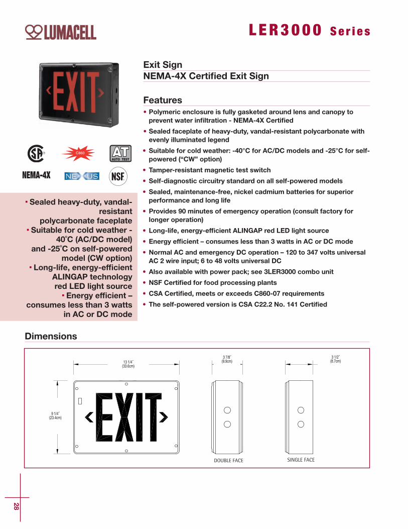
Exit SignNEMA-4X Certified Exit Sign
Features• Polymeric enclosure is fully gasketed around lens and canopy toprevent water infiltration - NEMA-4X Certified
• Sealed faceplate of heavy-duty, vandal-resistant polycarbonate withevenly illuminated legend
• Suitable for cold weather: -40°C for AC/DC models and -25°C for self-powered (“CW” option)
• Tamper-resistant magnetic test switch
• Self-diagnostic circuitry standard on all self-powered models
• Sealed, maintenance-free, nickel cadmium batteries for superiorperformance and long life
• Provides 90 minutes of emergency operation (consult factory forlonger operation)
• Long-life, energy-efficient ALINGAP red LED light source
• Energy efficient – consumes less than 3 watts in AC or DC mode
• Normal AC and emergency DC operation – 120 to 347 volts universalAC 2 wire input; 6 to 48 volts universal DC
• Also available with power pack; see 3LER3000 combo unit
• NSF Certified for food processing plants
• CSA Certified, meets or exceeds C860-07 requirements
• The self-powered version is CSA C22.2 No. 141 Certified
Dimensions
DOUBLE FACE SINGLE FACE
13 1/4˝(33.6cm)
9 1/4˝(23.4cm)
3 7/8˝(9.9cm)
3 1/2˝(8.7cm)
L ER3000 Se r i e s
Sealed heavy-duty, vandal-resistant
polycarbonate faceplateSuitable for cold weather -
40˚C (AC/DC model)and -25˚C on self-powered
model (CW option)Long-life, energy-efficient
ALINGAP technology red LED light source
Energy efficient –consumes less than 3 watts
in AC or DC mode
NEMA-4X

460.0079 Wall Mount460.0027 End Mount460.0028 Ceiling Mount
29
LER3000 S
erie
s
DC Specs6 to 48Vdc Less than 2W6 to 48Vdc Less than 2WNiCad battery Min. 90 minutesNiCad battery Min. 90 minutes
ModelAC/DC redAC/DC greenSelf-powered redSelf-powered green
AC Specs120 to 347Vac Less than 3W120 to 347Vac Less than 3W120 to 347Vac Less than 3W120 to 347Vac Less than 3W
Power Consumption
With heads
Wire Guards
Ordering Information
LER3 500 WH 4X
Series Faces/Mounting Housing/Faceplate Colour Voltage Options Cabinet
LER3 =C860
approved
500 = single face,universal mount 600 = double face,universal mount
WH = factory white/whiteBK = black/blackBW = black/white
WB = factory white/blackGA = grey/greyGW = grey/whiteGB = grey/black
Blank = universal120-347Vac, 6-48Vdc
SPD = 120-347Vac,self-powered c/w
diagnostics (non-audible)120VACDC2 =
120Vac, 120Vdc 2wires (AC only)
Blank = no optionsGN = green letters
FA = _re alarm activated`asher
*FB = `asher/buzzerCW = cold weather
(-25°C for self-powered, -40°C for AC/DC)
**NEX = Nexus System inter-face
* Self-powered models only** Not available with
(FA, FB, CW)
4X = approvedNEMA-4X
EXAMPLE:
Typical SpecificationSupply and install Lumacell LER3000Series LED exit signs. The equipment shalloperate with universal two-wire AC inputvoltage from 120Vac to 347Vac at lessthan 3 watts and universal two-wire DCinput voltage from 6Vdc to 48Vdc at lessthan 2 watts for single and double facesigns. The equipment frame shall be ofindustrial grade polyvinyl chloride with agasket around lenses and canopydesigned specifically for hostileenvironments. The faceplate(s) shall beconstructed of heavy-duty vandal-resistantpolycarbonate and feature an evenilluminated legend. The light source shallbe light emitting diodes (LED). Red LEDtechnology shall be Alingap. An LED-sensitive diffuser shall be mounted behindthe legend to provide the 6” high by 3/4”stroke letters with even illumination. Theexit shall be certified for NEMA-4X anddesigned specifically for high abuse areas,
wet location, and cold weather (-25°C)applications. The self-powered model shallstay illuminated during emergencyoperation for at least 90 minutes upon ACfailure and shall include a magnetic testswitch and self-testing and self-diagnosticfunctions. The equipment shallautomatically self test for 5 minutes every30 days, 30 minutes every 60 days and 90minutes annually. A “Service Required”lamp shall be located near the test switchand flash when a fault is detected. A two-LED diagnostic display shall be locatedinside the equipment and shall identify theeventual source of failure (battery, chargercircuitry, or LED lamps).
The exit sign shall be CSA-C860-07approved.
The exit sign shall be Lumacell Model -_____________________________________.

30
RG -X Se r i e s H a z a r d ou s L o c a t i o n
Features• CSA Certified for use in hazardous locations:
• Class I, Divisions 1 and 2, Groups A, B, C, D• Class II, Divisions 1 and 2, Groups E, F, G• Class III, Divisions 1 and 2
• Die-cast aluminum body with gray epoxy powder coat finish; clear,impact and heat resistant prismatic glass globe
• Long-life, maintenance-free lead-calcium battery• Battery charger is current limited, temperature compensated, short-circuit proof and reverse polarity protected
• Emergency heads with one or twin lamp design• Self-powered exit (combo) includes a transfer circuit to drive fourremote LED-based exit signs
• Exit sign uses a LED lamp with ALINGAP LEDs• Exit sign is CSA certified, meets or exceeds C860-07 requirements • The self-powered version is also CSA C22.2 No. 141 certified• Easy-to-build catalogue number based on the Lumacell SeverityCodes
• Also available as remote exit signs and remote fixtures; refer to theLERE-XP and RS10XP catalogue sheets
Typical Specification
Battery Units, Self-Powered Exit Signs, Combination UnitsCSA certified for use in hazardous locationsClass I, Zone 1, Groups IIC, IIB and IIA for Severity Code 1 productsClass I, Zone 1, Groups IIB and IIA for Severity Code 2 productsClass I, Zone 2, Groups IIC, IIB and IIA for Severity Code 3 products
The RG-X Series of batteryequipment is designed tocover emergency lightingapplications for the entirespectrum of hazardous
locations, whereinflammable gases, vapors,
liquids, dust particles orfabrics tissues are
permanently present or arelikely to exist.
The RG-X Series combinesin one simple-to-ordercatalogue family threetraditional emergencylighting products with
battery back-up: batteryunits with emergency lights,self-powered exit signs, and
combination units withemergency lights and exit
sign. The equipment is alsoavailable with additional
emergency power capacityto drive remote heads and
exit signs.
Supply and install the Lumacell RG-XSeries of hazardous location batteryequipment. The battery unit housing willbe constructed of die cast aluminumwith gray epoxy powder coat _nish. Theequipment shall be rated for 120, 277 or347 volts, 60 Hz input and be CSA listed.The equipment shall have an output of____ volts and ___ watts and shall supplythe rated load for a minimum of a 1/2hour to 87,5% of the rated batteryvoltage. The battery shall be a long-life,maintenance-free lead-calcium type. Thecharger shall be fully computer testedand have its charge voltage set in thefactory to ± 1% tolerance. The chargershall be current limited, temperaturecompensated, short-circuit proof andreverse polarity protected. The chargershall be furnished with an electroniclockout circuit, which will connect thebattery when the AC circuit is activated,and an electronic brownout circuit, whichwill activate the emergency heads whenthe utility power dips below 75% ofnominal voltage.Where required the equipment shall comecomplete with ____ heads, each of them
equipped with ___ lamp(s) of ____ watts.The head housing shall be die-castaluminum with gray epoxy powder coat_nish. The lenses shall be a clear, impactand heat resistant prismatic glass globe.The head shall be factory sealed, with noneed for external seals.Where required the equipment shall comecomplete with one exit sign and willinclude a transfer circuit to maintain theexit sign permanently lighting in bothnormal and emergency operation. The exithousing shall be industrial grade 14-gaugesteel and _nished in gray enamel. Thefaceplate will be constructed of heavy-duty 14-gauge steel and feature universalknockout chevrons and the red lettersshall not be less than 6” (150 mm) inheight with a 3/4” (19 mm) stroke. Thesign shall include a LED lamp withALINGAP LEDs and shall consume lessthan 5 watts in either AC or battery mode. The equipment shall be suitable forClass ___ Division ___ Group ____. The exit sign shall be CSA-C860-07approved.The equipment shall be the LumacellModel - ________________________.

31
RG-X
Serie
s
Dimensions
Before ordering, identify theenvironment of your application:Class___, Division___, Group___. Referto the following chart for the SeverityCode to use in your cataloguenumber:________________________ .
S1 S2S3S4
Severity CodeCl. I, Div. 1, Gr. A, BCl. I, Div. 1, Gr. C, DCI. I, Div. 2, Gr. A, B, C, D Cl. II, Div. 1 & 2, Gr. E, F, GCl. III, Div. 1 & 2
Environment
SMALL CABINET
LARGE CABINET
Ordering Information
RG 6 36 X A1 12W S3 TD
SeriesD.C.
VoltageCapacity/
Cabinet SizeHousing Faces
HeadStyle
Lamps SeverityCode
A.C.Voltage
Options
RG 6 = 6 volts
12 = 12 volts
24 =24 volts
36 = 36 watts [S]*72 = 72 watts [S]*108 = 108 watts [L]*72 = 72 watts [S]*144 = 144 watts [L]*200 = 200 watts [L]*144 = 144 watts [L]*288 = 288 watts [L]*
* Cabinet size is notpart of the orderinginformation. Housing
X =hazardouslocation
Blank =no exit signRE1 =
single faceexit signC860,L.E.D.RE2 =
double faceexit signC860,L.E.D.
-0 = noheads
A1 = singleremote, 1lamp
A2 = singleremote, 2lamps
A3 = dou-ble remote,1 lamp
12W = halogen,6V, 12V - 12 watts,
quartz bi-pin20W = halogen,
12V, 24V - 20 watts,quartz bi-pin
Note: for other lampoptions, pleasecontact factory.
S1 =see chartS2 =
see chartS3 =
see chartS4 =
see chart
Blank =120VacZC =277VacinputZD =347Vacinput
Blank =no optionsTD =
time delayTP =
transferpanel
EXAMPLE:
The temperature code of completeequipament is given by the type ofemergency head or Exit Sign installed.For temperature information, pleaselook at the table below:
Temperature Codes for LERE-XPSeries Exit Signs (40°C ambient)
Severity Code S1 S2 S3 S4
TemperatureCode
T6 T6 T3CT3C(EGF)
CSA/ULrating
Max85°C
Max85°C
Max160°C
Max160°C
103/8”[26.4cm]
181/4”[46.5cm]
195 /8 ”
[48.
9cm
]
95 /8 ”[2
4.4c
m]
131/8”[33.4cm]
211/4” [53.9cm]
201 /8 ”
[51.
0cm
]
10”
[25.
4cm
]
207/8”[53.0cm]
227 /8 ”
[58.
0cm
]
273/4” [70.5cm] 143/8” [36.6cm]
63/8” [16.3cm]
195 /8 ”
[49.
9cm
]
227 /8 ”
[58.
1cm
]
233/4” [60.4cm]
233 /8 ”
[59.
2cm
]
305/8” [77.8cm] 143/8” [36.6cm]
61/4”[20.8cm]
201 /8 ”
[51.
0cm
]
233 /8 ”
[59.
2cm
]
32
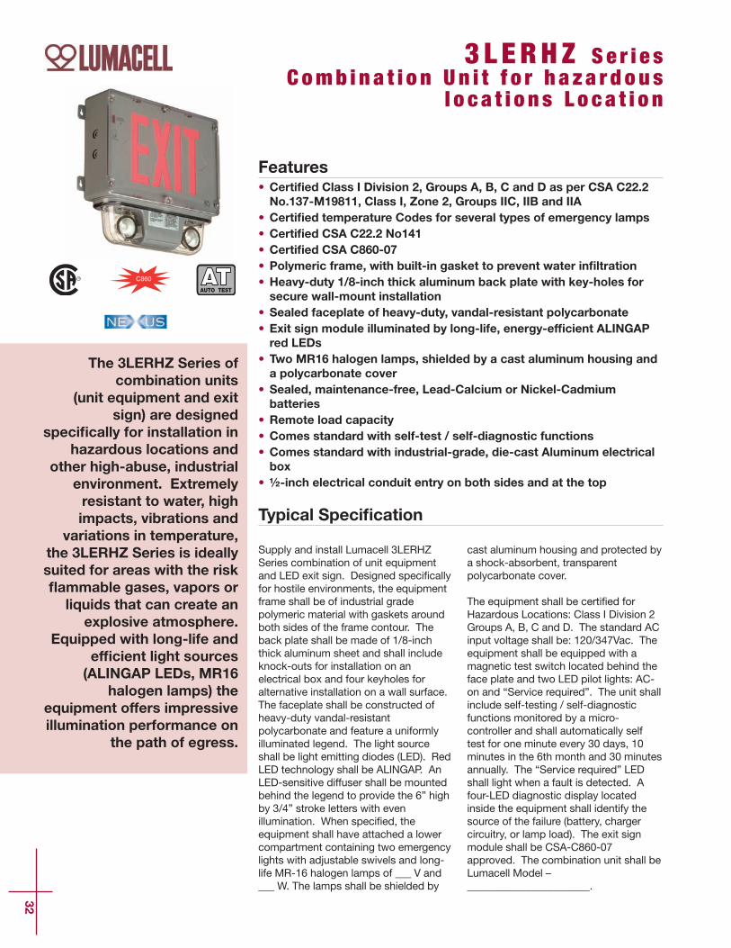
Features• Certified Class I Division 2, Groups A, B, C and D as per CSA C22.2No.137-M19811, Class I, Zone 2, Groups IIC, IIB and IIA
• Certified temperature Codes for several types of emergency lamps• Certified CSA C22.2 No141 • Certified CSA C860-07 • Polymeric frame, with built-in gasket to prevent water infiltration• Heavy-duty 1/8-inch thick aluminum back plate with key-holes forsecure wall-mount installation
• Sealed faceplate of heavy-duty, vandal-resistant polycarbonate• Exit sign module illuminated by long-life, energy-efficient ALINGAPred LEDs
• Two MR16 halogen lamps, shielded by a cast aluminum housing anda polycarbonate cover
• Sealed, maintenance-free, Lead-Calcium or Nickel-Cadmiumbatteries
• Remote load capacity• Comes standard with self-test / self-diagnostic functions • Comes standard with industrial-grade, die-cast Aluminum electricalbox
• ½-inch electrical conduit entry on both sides and at the top
Typical Specification
The 3LERHZ Series ofcombination units
(unit equipment and exitsign) are designed
specifically for installation inhazardous locations and
other high-abuse, industrialenvironment. Extremelyresistant to water, highimpacts, vibrations and
variations in temperature,the 3LERHZ Series is ideallysuited for areas with the riskflammable gases, vapors orliquids that can create an
explosive atmosphere.Equipped with long-life and
efficient light sources(ALINGAP LEDs, MR16
halogen lamps) theequipment offers impressiveillumination performance on
the path of egress.
Supply and install Lumacell 3LERHZSeries combination of unit equipmentand LED exit sign. Designed speci_callyfor hostile environments, the equipmentframe shall be of industrial gradepolymeric material with gaskets aroundboth sides of the frame contour. Theback plate shall be made of 1/8-inchthick aluminum sheet and shall includeknock-outs for installation on anelectrical box and four keyholes foralternative installation on a wall surface.The faceplate shall be constructed ofheavy-duty vandal-resistantpolycarbonate and feature a uniformlyilluminated legend. The light sourceshall be light emitting diodes (LED). RedLED technology shall be ALINGAP. AnLED-sensitive diffuser shall be mountedbehind the legend to provide the 6” highby 3/4” stroke letters with evenillumination. When speci_ed, theequipment shall have attached a lowercompartment containing two emergencylights with adjustable swivels and long-life MR-16 halogen lamps of ___ V and___ W. The lamps shall be shielded by
cast aluminum housing and protected bya shock-absorbent, transparentpolycarbonate cover.
The equipment shall be certi_ed forHazardous Locations: Class I Division 2Groups A, B, C and D. The standard ACinput voltage shall be: 120/347Vac. Theequipment shall be equipped with amagnetic test switch located behind theface plate and two LED pilot lights: AC-on and “Service required”. The unit shallinclude self-testing / self-diagnosticfunctions monitored by a micro-controller and shall automatically selftest for one minute every 30 days, 10minutes in the 6th month and 30 minutesannually. The “Service required” LEDshall light when a fault is detected. Afour-LED diagnostic display locatedinside the equipment shall identify thesource of the failure (battery, chargercircuitry, or lamp load). The exit signmodule shall be CSA-C860-07approved. The combination unit shall beLumacell Model –_______________________.
3 L ERHZ Se r i e s C omb i n a t i o n U n i t f o r h a z a r d ou s
l o c a t i o n s L o c a t i o n

Model AC SpecsWattage Capacity
30 min. 1 hr. 1.5 hrs. 2 hrs. 4 hrs.3LERHZ 120/347 Vac 0.15 / 0.06 Amp 36 21 15 12 -3LERHZN 120/347 Vac 0.15 / 0.06 Amp 36 30 20 15 -5LERHZN 120/347 Vac 0.30 / 0.10 Amp 60 40 30 20 10
Lamp Rating Temperature Code Max. Temperature Replacement part #6V 10W T3C 160 °C 580.007912V 12W T3A 180 °C 580.008012V 20W T2D 215 °C 580.0068
33
3LERHZ S
erie
s
Dimensions
Ordering Information
Power Consumption and Unit Rating
Temperature Codes
Note: Use qualified replacement lamps to avoid risk of over-heating
3LERHZ 2 MJ GG AT
Series # of Heads Lamp/WattageHousing/Face
ColorVoltage
LettersColor
Options
3LERHZ=6V - 36W, lead acid
3LERHZN =6V - 36W, NiCad
5LERHZ =12V - 60W NiCad
Blank = no heads
2 = 2 heads
MJ =MR16, 6V - 10W
MK =MR16, 12V - 12W
MW =MR16 12v- 20 w IR
GG = grey/grey Blank =120/347vac
ZC =120/277vac
Blank =red letters
G =green letters
AT =autotest audible
ATN =auto Test, non-
audibleNEX =
nexus systeminterface
EXAMPLE:
141/2” [36.8cm]31/2”
[8.9cm]
133/4” [34.9cm]
125 /8 ”
[32.
1cm
]
61 /4 ” [1
5.6c
m]


CATALOG
Remote
s

36
MQM-HZ Se r i e sHAZARDOUS LOCATION Compliant Remote FixtureClass I, Division 2, Groups A, B, C and DClass I, Zone 2, Groups IIC, IIB and IIA
Features• Certified Class I Division 2, Groups A, B, C and D as per CSA C22.2No. 9 and No.137-M1981, Class I, Zone 2, Groups IIC, IIB and IIA
• Temperature Codes: T3B (10W and 12W MR16 lamps) and T2C (20WMR16 lamps), as per Canadian Electrical Code, Part I and CSA C22.2No.137-M1981)
• Extreme operational temperature range: -40ºC to +40ºC.• Choice of single- or double-lamp models• High-efficacy MR16 halogen lamps of 10W, 12W and 20W (seespecification table)
• Input voltage: 6V, 12V, 24V or 120V• Fully gasketed die-cast aluminum back plate• Clear polycarbonate cover, UV and impact resistant• Easy installation on a 4-inch octagonal box (included in the package)• Comes standard with tamper-proof screws and bit
Typical Specification
Supply and install Lumacell MQM-HZ Series Model - ________________remote emergency lighting _xture.The _xture shall have a single- ordouble-lamp con_guration (asspeci_ed) and shall include a fullygasketed die-cast aluminum backplate and a clear heavy-duty UVresistant polycarbonate cover. The_xture shall come standard with a 4-inch octagonal box, stainless steeltamper-proof screws and dedicatedscrewdriver bit.
The _xture shall be certi_ed for usein hazardous locations Class I,Division 2, Groups A, B, C and D and
shall be listed to CSA C22.2 No. 9and CSA C22.2 No.137-M1981. The_xture shall be rated with atemperature code for the selectedlamps as in the table below. Each lamp in the _xture shall be ableto be oriented without tools andshould be equipped with highef_ciency MR16 halogen lamp(s) of___ Volts ___ Watts. The remote_xtures will provide illumination inemergency operation and shallreceive their DC power from theLumacell battery unit Model-________________________ . The _xture shall be Lumacell Model– _______________________.
Power ConsumptionLamp typeMR16MR16MR16
Input Voltage6 Volts
12, 24 Volts12, 24, 120 Volts
Power (each of 2 lamps)10 Watts12 Watts20 Watts
Temperature codeT3B (Max 165ºC)T3B (Max 165ºC)T2C (Max 230ºC)
The MQM-HZ Series ofremote fixtures has beendesigned specifically forinstallation in hazardouslocations and other andhigh-abuse, industrial
environments. Extremelyresistant to water, highimpacts, vibrations and
variations in temperature,the MQM-HZ Series is
suited for areas with the riskof presence of flammablegases, vapors or liquids
able to create an explosivegas atmosphere. Besidestheir superior endurance,
the fixtures haveoutstanding lighting
performance, with a center-to-center egress
illumination up to 70-footlong and 3-foot wide.
37
MQM-H
Z S
erie
s
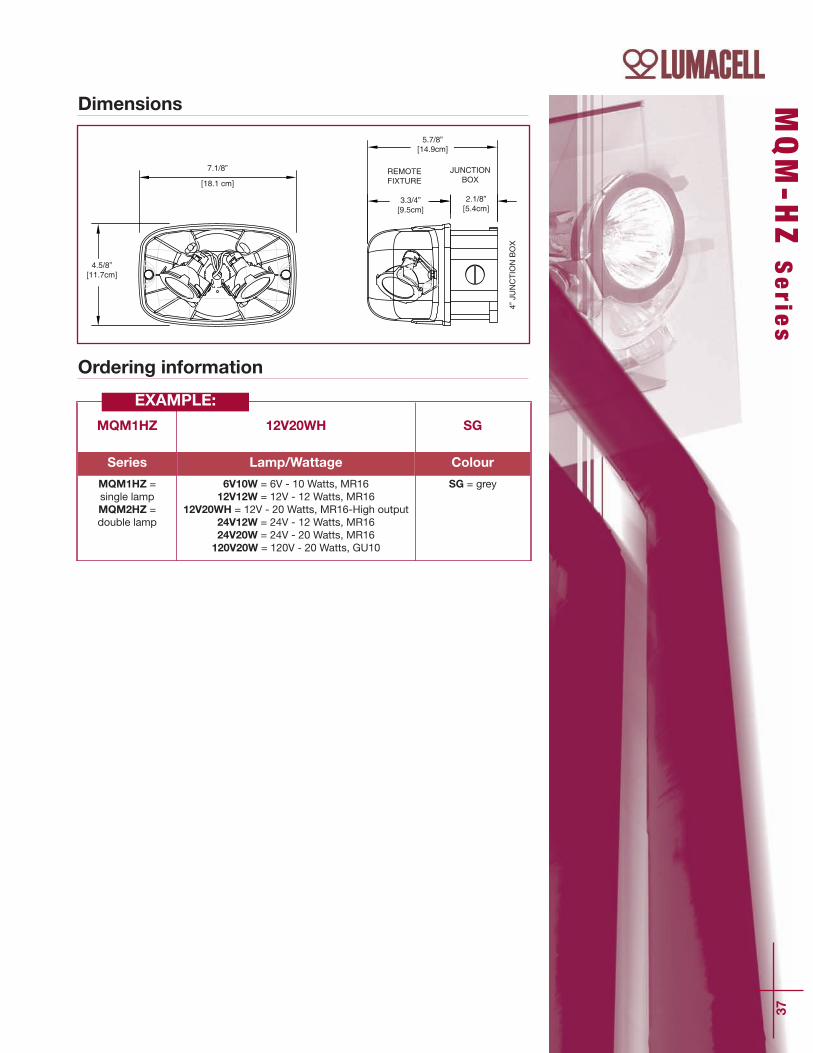
Dimensions
Ordering information
4.5/8”[11.7cm]
7.1/8”
[18.1 cm]
5.7/8”[14.9cm]
3.3/4”[9.5cm]
2.1/8”[5.4cm]
4” JUNCTION BOX
JUNCTION BOX
REMOTEFIXTURE
MQM1HZ 12V20WH SG
Series Lamp/Wattage Colour
MQM1HZ =single lampMQM2HZ =double lamp
6V10W = 6V - 10 Watts, MR1612V12W = 12V - 12 Watts, MR16
12V20WH = 12V - 20 Watts, MR16-High output24V12W = 24V - 12 Watts, MR1624V20W = 24V - 20 Watts, MR16120V20W = 120V - 20 Watts, GU10
SG = grey
EXAMPLE:

38
Features
• Delivers unsurpassed pathway illumination – 70 feet, center-to-center (with 12V 20W lamp)
• Fully gasketed cast aluminum back plate with clear polycarbonatecover – NEMA-4X Certified
• UV and impact resistant cover
• Choice of three colours: factory white, black or grey
• Choice of single or double head models
• Available in 6, 12 and 24 Volt models with various wattages
• High efficiency MR16 lamps up to 20W
• Easy installation on four-inch octagonal box
• Easy lamp replacement
• Comes standard with tamper-proof screws and bit
• NSF Certified for food processing plants
• CSA Certified to C22.2 No. 9
Remote FixtureNEMA-4X Certified Battery Unit
Choice of single or doublehead models
Fully gasketed castaluminum back
plate with clear UVresistant
polycarbonate cover
Choice of MR16 halogenlamps up to 24V, 20W orhigh-efficiency, 5-Watt,
MR16 LED lamps
NEMA-4X
MQM-NX Se r i e s
Typical SpecificationSupply and install Lumacell MQM NXSeries Model - _________________ remoteemergency lighting fixtures. These remotefixtures will consist of either single or doublelamp configurations according to thedesign. These fixtures shall be fullygasketed with a die cast aluminum backplate and a clear heavy-duty UV resistantpolycarbonate light cover. Units shall beNEMA-4X certified and specifically designedfor high abuse areas, wet and cold weatherlocations. The standard unit will come withstainless steel tamper-proof screws and bit.
The remote fixture shall be certified to CSAC22.2 No. 9 and NSF Certified for use infood processing plants.
The head(s) shall be fully adjustablewithout tools and should be equipped withhigh efficiency MR16 halogen lamp(s) of___ volts ___ watts.
The remote fixtures will provideillumination in emergency operation andreceive their DC power from Lumacellbattery unit Model- ___________________ .

39
Ordering Information
MQM1NX 6V6W
Series Lamp/Wattage Colour
MQM1NX =single, NEMA-4XMQM2NX =
double, NEMA-4X
6V6W = 6V-6 watts, MR166V10W = 6V-10 watts, MR1612V12W = 12V-12 watts, MR1612V20W = 12V-20 watts, MR1624V20W = 24V-20 watts, MR1624V12W = 24V-20 watts, MR16
L = 12V-5 watts, LED
Blank = factorywhite
BK = blackSG = grey
EXAMPLE:
Dimensions
4 5/8˝[11.7cm]
7 1/8˝[18.1cm]
3 3/4˝[9.5cm]
MQM-N
X S
erie
s

40
Sa f - T- R a y S e r i e sWa l l Moun t R emo t e H e ad
Robust, vandal resistant, versatile wall mount fixture
Features• Compact wall sconce unit for indoor and outdoor use• High impact resistant polycarbonate diffuser• Die-cast aluminum housing• Available in factory white, black or dark grey finish• Adjustabe lamps• Vandal resistant option
Typical SpecificationWall mount unit shall be gasketed die-cast aluminum housing, impactresistant polycarbonate diffuser.
To be supplied in factory white, black or dark grey. The lamps shall be inadjustable for aisle or area distribution.
Fixture shall be supplied with gasket and shall be
suitable for installation on any four inch octogonal box.
Lamp shall be model ____, ____ watts Model Saf-T-Ray by Lumacell.
The Saf-T-RayTM wallsconce unit was designed
and engineered withdurability and
sophistication in mind.Its low-profile aestheticdesign will provide an
attractive alternative tothe typical two-headedstandard emergency
lighting unit. The Saf-T-RayTM is
suitable for outdoor andindoor use, in a widerange of applications
where aesthetics cannotbe compromised.
MQM-H
Z S
erie
s
41
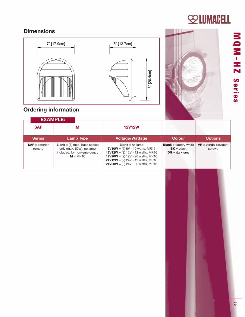
SAF M 12V12W
Series Lamp Type Voltage/Wattage Colour Options
SAF = exteriorremote
Blank = (1) med. base socketonly (max. 60W), no lamp
included, for non-emergencyM = MR16
Blank = no lamp6V10W = (2) 6V - 10 watts, MR1612V12W = (2) 12V - 12 watts, MR1612V20W = (2) 12V - 20 watts, MR1624V12W = (2) 24V - 12 watts, MR1624V20W = (2) 24V - 20 watts, MR16
Blank = factory whiteBK = black
DG = dark grey
VR = vandal resistantscrews
EXAMPLE:
Dimensions
Ordering information
42
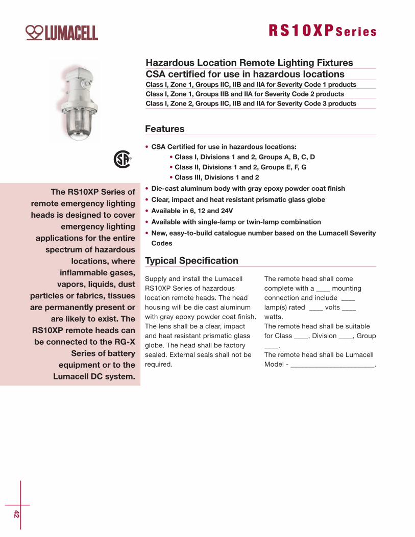
RS10XP Se r i e s
Hazardous Location Remote Lighting FixturesCSA certified for use in hazardous locationsClass I, Zone 1, Groups IIC, IIB and IIA for Severity Code 1 productsClass I, Zone 1, Groups IIB and IIA for Severity Code 2 productsClass I, Zone 2, Groups IIC, IIB and IIA for Severity Code 3 products
Features
• CSA Certified for use in hazardous locations:
• Class I, Divisions 1 and 2, Groups A, B, C, D
• Class II, Divisions 1 and 2, Groups E, F, G
• Class III, Divisions 1 and 2
• Die-cast aluminum body with gray epoxy powder coat finish
• Clear, impact and heat resistant prismatic glass globe
• Available in 6, 12 and 24V
• Available with single-lamp or twin-lamp combination
• New, easy-to-build catalogue number based on the Lumacell Severity
Codes
Typical Specification
Supply and install the LumacellRS10XP Series of hazardouslocation remote heads. The headhousing will be die cast aluminumwith gray epoxy powder coat finish.The lens shall be a clear, impactand heat resistant prismatic glassglobe. The head shall be factorysealed. External seals shall not berequired.
The remote head shall comecomplete with a ____ mountingconnection and include ____lamp(s) rated ____ volts ____watts. The remote head shall be suitablefor Class ____, Division ____, Group____. The remote head shall be LumacellModel - ________________________.
The RS10XP Series ofremote emergency lightingheads is designed to cover
emergency lightingapplications for the entirespectrum of hazardous
locations, whereinflammable gases,vapors, liquids, dust
particles or fabrics, tissuesare permanently present or
are likely to exist. TheRS10XP remote heads canbe connected to the RG-X
Series of batteryequipment or to the
Lumacell DC system.

Certification Guide for Remote Lighting Fixtures (40°C ambient)
43
DimensionsDOUBLE PENDANT MOUNT
SEVERITY S1, S2, S3
SEVERITY S3, S4
CEILING MOUNT WALL MOUNT PENDANT MOUNT
SeverityCodeS1 S2S3S4
Environment
Cl. I, Div. 1, Gr. A, BCl. I, Div. 1, Gr. C, D
CI. I, Div. 2, Gr. A, B, C, D Cl. II, Div. 1 & 2, Gr. E, F, G
Cl. III, Div. 1 & 2
Before ordering, identify theenvironment of your application:Class___, Division___, Group___.Refer to the following chart for theSeverity Code to use in yourcatalogue number:
RS10XPSerie
s
Ordering Information
For additional information, please look at the table below:
Severity CodeTemperature CodeCSA/UL rating
S1T4A
Max 120°C
S2T6
Max 85°C
S3T1
Max 450°C
S4T3B (EGF)Max 165°C
RS10XP 6V 12W S3 P
Series Voltage Lamp Wattage/Type Severity Code Mounting
RS10XP = single remote 1 lampRS20XP = single remote 2 lamps*RS20FXP = double remote 1 lamp*
*Pendant mount only
6V = 6 volts12V = 12 volts24V = 24 volts
12W =halogen, 6V, 12V-12 watts, quartz bi-pin
20W =halogen,12V, 24V- 20 watts, quartz bi-pin
Note: For other lamp options,please contact factory.
S1 = see chartS2 = see chartS3 = see chartS4 = see chart
C = ceiling mountP = pendant mountW = wall mount
EXAMPLE:
71/4” [18.4cm]71/4” [18.4cm]
71/4” [18.4cm]135/8” [34.6cm]
51/4”[13.3cm]
251/4” [64.0cm]
115 /8 ”
[29.
5cm
]
75 /8 ” [1
8.1c
m]
95 /8 ” [2
4.5c
m]
141 /8 ”
[34.
9cm
]
151 /4 ”
[38.
8cm
]
115 /8 ”
[29.
5cm
]
293 /4 ”
[75.
6cm
]
6” [1
5.3c
m]
6” [1
5.3c
m]
21” [
53.3
cm]
7” [17.8cm]
7” [17.6cm] 7” [17.8cm]
103/4” [27.3cm]17/8” [4.8cm]4”
[10.1cm]
251/8” [63.7cm]
91 /8 ” [2
3.0c
m]
3” [7
.7cm
]
35 /8 ” [9
.3cm
]
177 /8 ”
[45.
5cm
]
95 /8 ” [2
4.3c
m]
93 /8 ” [2
3.8c
m]
33 /8 ” [8
.4cm
]
91 /8 ” [2
3.0c
m]
263 /4 ”
[67.
9cm
]
6” [1
5.3c
m]
6” [1
5.3c
m]
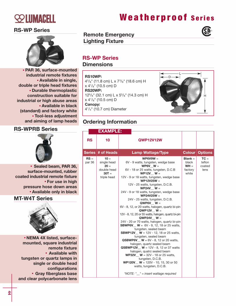
MT-W4T Series
NEMA 4X listed, surface-mounted, square industrial
remote fixtureAvailable with
tungsten or quartz lamps insingle or double head
configurationsGray fiberglass base
and clear polycarbonate lens
RS-WP Series
PAR 36, surface-mountedindustrial remote fixtures
Available in single,double or triple head fixtures
Durable thermoplasticconstruction suitable for
industrial or high abuse areasAvailable in black
(standard) and factory whiteTool-less adjustment
and aiming of lamp heads
44
Wea t h e r p r o o f Se r i e s
Remote EmergencyLighting Fixture
RS-WP SeriesDimensions
DL
H
RS10WP:45/8" (11.8 cm) L x 73/8" (18.6 cm) Hx 41/8" (10.5 cm) DRS20WP:125/8" (32.1 cm) L x 55/8" (14.3 cm) Hx 41/8" (10.5 cm) DCanopy:41/4" (10.7 cm) Diameter
Ordering Information
RS 10 QWP12V12W
Series # of Heads Lamp Wattage/Type Colour Options
RS =par 36
10 =single head
20 =double head
30T =triple head
WP6V9W = 6V - 9 watts, tungsten, wedge base
WP6V__W = 6V - 18 or 25 watts, tungsten, D.C.B
WP12V__ W = 12V - 9 or 18 watts, tungsten, wedge base
WP12V25W = 12V - 25 watts, tungsten, D.C.B.
WP24V__ W = 24V - 9 or 18 watts, tungsten, wedge base
WP24V25W = 24V - 25 watts, tungsten, D.C.B.
QWP6V__ W = 6V - 8, 12, or 20 watts, halogen, quartz bi-pin
QWP12V__ W =12V - 8, 12, 20 or 55 watts, halogen, quartz bi-pin
QWP24V__ W =24V - 20 or 70 watts, halogen, quartz bi-pin SBWP6V__ W = 6V - 9, 12, 18 or 25 watts,
tungsten, sealed beamSBWP12V__ W = 12V - 12, 18 or 25 watts,
tungsten, sealed beamQSBWP6V__ W = 6V - 8, 12 or 20 watts,
halogen, quartz sealed beam QSBWP12V__ W = 12V - 8, 12 or 37 watts
halogen, quatrz sealed beamWP32V__ W = 32V - 18 or 25 watts,
tungsten, D.C.B.WP120V__ W = 120V - 10, 15, 30 or 50
watts, tungsten, D.C.B.
*NOTE: "__" = insert wattage required
Blank =blackWH =factorywhite
TC =te`oncoatedlens
EXAMPLE: RS-WPRB Series
Sealed beam, PAR 36,surface-mounted, rubber
coated industrial remote fixtureFor use in high
pressure hose down areasAvailable only in black

45
Weath
erp
roofSerie
s
MT-W4T SeriesDimensions
RS-WPRB SeriesDimensions
RS10-WPRB:45/8" (11.8 cm) L x 73/8" (18.6 cm) H x 41/8" (10.5 cm) DRS20-WPRB:125/8" (32.1 cm) L x 55/8" (14.3 cm) H x 41/8" (10.5 cm) DCanopy:41/4" (10.7 cm) Diameter
MT1-W4T:5.0” (12.8 cm) L x 5.0” (12.8 cm) H x 4.0’’ (10.2 cm) DMT2-W4T:7.0” (17.8 cm) L x 5.0” (12.8 cm) H x 4.0’’ (10.2 cm) D
D
H
L
D
L
H
Ordering Information
RS 10 SBWPRB6V9W
Series # of Heads Lamp Wattage/Type Options
RS =par 36
10 =single head
20 =double head
30T =triple head
SBWPRB6V __ W = 6V - 9, 12, 18 or 25 watts,tungsten, sealed beam
SBWPRB12V __ W = 12V - 12, 18 or 25 watts,tungsten, sealed beam
QSBWPRB6V __ W = 6V - 8, 12 or 20 watts,halogen, quartz sealed beam
QSBWPRB12V __ W = 12V - 8, 12 or 37 watts,halogen, quatrz sealed beam
*NOTE: "__" = insert wattage required
TC =te`on
coated lens
MQ 1W4T 12V12W
Series # of Heads Lamp Wattage/Type
MT =tungstenMQ =halogen
1W4T =single head 2W4T =
double head
6V9W = 6V - 9 watts, tungsten, wedge base12V __ W = 12V - 9 or 18 watts, tungsten, wedge base24V __ W = 24V - 9 or 18 watts, tungsten, wedge base6V __ W = 6V - 8, 12, or 20 watts, halogen, quartz bi-pin12V __ W = 12V - 8, 12, or 20 watts, halogen, quartz bi-pin
24V20W = 24V - 20 watts, halogen, quartz bi-pin
*NOTE: "__" = insert wattage required
EXAMPLE:
EXAMPLE:
Ordering Information

Cubic, vandal-resistantsurface-mounted fixture
Single, double or twin cubewith center body
Available in factory white(standard) and black with
frosted polycarbonate cube
46
Su r f a c e Moun t e d S e r i e s
RS10/RS20/RS30T Series
Dimensions
Remote EmergencyLighting Fixtures
RS10: 4.5” (11.4 cm) L x 7.25” (18.4 cm) H x 3.5” (8.9 cm) D Canopy: 5.0” (12.7 cm) Diameter
RS20: 4.5” (11.4 cm) L x 7.25” (18.4 cm) H x 11.75” (29.9 cm) DCanopy: 5” (12.7 cm) Diameter
RS30T: 14.0” (35.6 cm) L x 7.25” (18.4 cm) H x 14.0” (35.6 cm) DCanopy: 9.5” (24.1 cm) Diameter
L
D
H
PAR36, surface-mounted, large remote
fixturesSingle, double or
triple headPositive aim swivelAvailable in factory
white (standard) and black
RS10/RS20/RS30T
RSQB/RSQBD/RSQB2
RS 10 Q12V12W
Series # of Heads Lamp Wattage/Type Colour Options
RS =par 36
10 =single head
20 =double head
30T =triple head
6V9W =6V - 9 watts, tungsten, wedge base
6V __W = 6V - 18 or 25 watts, tungsten, D.C.B
12V __ W = 12V - 9 or 18 watts, tungsten, wedge base
12V25W = 12V - 25 watts, tungsten, D.C.B.
24V __ W =24V - 9 or 18 watts, tungsten, wedge base
24V25W = 24V - 25 watts, tungsten, D.C.B.
Q6V __ W =6V - 8, 12, or 20 watts, halogen, quartz bi-pinQ12V __ W = 12V - 8, 12, 20 or 55 watts,
halogen, quartz bi-pinQ24V __ W = 24V - 20 or 70 watts, halogen,
quartz bi-pinSB6V __ W = 6V - 9, 12, 18 or 25 watts,
tungsten, sealed beamSB12V __ W = 12V - 12, 18 or 25 watts,
tungsten, sealed beamQSB6V __ W = 6V - 8, 12 or 20 watts,
halogen, quartz sealed beamQSB12V __ W = 12V - 8, 12 or 37 watts,
halogen, quatrz sealed beam32V __ W =
32V - 18 or 25 watts, tungsten, D.C.B.120V __ W = 120V - 10, 15, 30 or 50
watts,tungsten, D.C.B.
*NOTE: "__" = insert wattage required
Blank =factorywhiteBK =black
TC =te`oncoatedlens
Ordering Information
EXAMPLE:

47
RSQB/RSQBD/RSQB2 Series
Dimensions
RSQB: 43/4” (12.1 cm) L x 47/8” (12.4 cm) H x 43/4” (12.1 cm) D
RSQBD: 91/2” (24.1 cm) L x 57/8” (15.0 cm) H x 43/4” (12.1 cm) D
RSQB2: 143/4” (37.4 cm) L x 43/4” (11.9 cm) H x 41/2” (11.3 cm) D
L
D
H
Surfa
ce M
ounte
d S
erie
s
RSQB 6V8W
Series Special Options Lamp Wattage/Type Colour
RSQB =single cubeRSQBD =double cubeRSQB2 =twin cube
Blank = no optionsT = tamper proof
screws
6V9W = 6V - 9 watts, wedge base 12V9W = 12V - 9 watts, wedge base12V18W = 12V - 18 watts, wedge base24V9W = 24V - 9 watts, wedge base 6V8W = 6V - 8 watts, quartz bi-pin6V12W = 6V - 12 watts, quartz bi-pin12V8W = 12V - 8 watts, quatrz bi-pin12V12W = 12V - 12 watts, quatrz bi-pin24V20W = 24V - 20 watts, quartz bi-pin
M6V6W = 6V - 6 watts, MR16 M6V10W = 6V - 10 watts, MR16M12V12W = 12V - 12 watts, MR16 M12V20W = 12V - 20 watts, MR16 M12V35W = 12V - 35 watts, MR16 M12V50W = 12V - 50 watts, MR16 M24V20W = 24V - 20 watt, MR16 M24V35W = 24V - 35 watts, MR16 M24V50W = 24V - 50 watts, MR16
Blank =factory white
BK =black
Ordering Information
EXAMPLE:


CATALOG
Batte
ry U
nits

50
RGS -D T S e r i e s
Features• Solid-state pulse-type charger – current-limited, temperature-compensated, short-circuit proof and reverse-polarity protected.
• Unit comes standard with electronic lockout and brownout circuits
• Sealed dust-proof transfer relay, test switch and LED indicator lights
• Long-life, maintenance-free sealed lead acid battery
• Wide range of lampheads available – consult Ordering Informationfor complete list
• Standard 120/347Vac input voltage with line cord kit
• NEXUS® compatible (for more information on NEXUS®, pleaseconsult the factory)
• CSA C22.2 No. 141 certified
Typical Specification
NEMA-12 Classified, 6, 12 and 24 Volts Battery UnitsHarsh environment emergency lighting units-steel,thermoplastic or fiberglass cabinets
Supply and install a completeemergency lighting system asdescribed herein and shown onthe drawings.The Lumacell Smart Diagnostic Microcontroller board shall supply the ratedload for a minimum of a 1/2 hour to87.5% of the rated battery voltage.The unit shall be rated 120V or 347V,60 Hz and be CSA listed. The unitshall have an output of _______ volts.The charger shall be fully computertested and its charge voltage factoryset to ± 1% tolerance. Chargers with_eld-adjusted potentiometers are notacceptable. A pulse-type chargershall be employed to promote longbattery life and reduce the potentialfor grid corrosion. The charger shallprovide a continuous high charge torecharge the battery, when thebattery is at full capacity, the chargerwill shut-off. Periodically the chargershall provide a pulse of energy tokeep the battery topped off. ThePulse charge shall be current limitedand precisely regulated by a micro-processing circuit, which samples thebattery in relation to its temperature,state or charge and input voltage`uctuations. The charger shall be
current limited, temperaturecompensated, short-circuit proof andreverse polarity protected. The unitshall be furnished with an electroniclockout circuit, which will connect thebattery when the AC circuit isactivated, and an electronicbrownout circuit, which will activatethe emergency lights when utilitypower dips below 75% of nominalvoltage. A low voltage batteryprotection circuit shall be providedand will disconnect the battery formthe fused output circuit at the end ofdischarge. The unit shall self-test for1 minute every 30 days, 10 minuteson the 6th month and 30 minutesevery 12 months. The unit shall becapable of full recharge incompliance with CSA speci_cations.The unit shall be furnished withsealed dust tight relay, a test switchand diagnostic LED indicator lights tocontinuously monitor the status ofthe unit: Battery Failure, BatteryDisconnected, Charger Failure, LampFailure, Service Alarm, AC “ON”,Charger High Rate.
The unit shall be Lumacell Model -________________________________ .
The RGS-DT Series batteryunits are specificallydesigned for use in
industrial facilities whereequipment is exposed to
dust, water, oil or corrosivesubstances. NEMA-12classified to protect
circuitry from harmful dustor liquid sprays, sealed andgasketed unit cabinets are
available in steel,thermoplastic or fiberglass
in a variety of sizes.
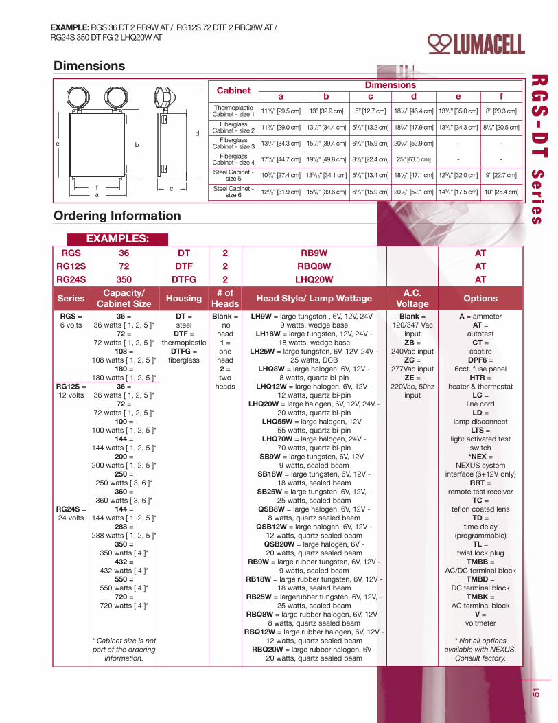
51
RGS-D
T S
erie
s
a
b
c
d
e
f
Dimensions
Ordering Information
EXAMPLE:RGS 36 DT 2 RB9W AT / RG12S 72 DTF 2 RBQ8W AT / RG24S 350 DT FG 2 LHQ20W AT
RGS 36 DT 2 RB9W ATRG12S 72 DTF 2 RBQ8W ATRG24S 350 DTFG 2 LHQ20W AT
SeriesCapacity/
Cabinet Size Housing
# ofHeads
Head Style/ Lamp WattageA.C.
Voltage Options
RGS = 6 volts
RG12S = 12 volts
RG24S = 24 volts
36 =36 watts [ 1, 2, 5 ]*
72 =72 watts [ 1, 2, 5 ]*
108 =108 watts [ 1, 2, 5 ]*
180 =180 watts [ 1, 2, 5 ]*
36 =36 watts [ 1, 2, 5 ]*
72 =72 watts [ 1, 2, 5 ]*
100 =100 watts [ 1, 2, 5 ]*
144 =144 watts [ 1, 2, 5 ]*
200 =200 watts [ 1, 2, 5 ]*
250 =250 watts [ 3, 6 ]*
360 =360 watts [ 3, 6 ]*
144 =144 watts [ 1, 2, 5 ]*
288 =288 watts [ 1, 2, 5 ]*
350 =350 watts [ 4 ]*
432 =432 watts [ 4 ]*
550 =550 watts [ 4 ]*
720 =720 watts [ 4 ]*
* Cabinet size is notpart of the ordering
information.
DT = steelDTF =
thermoplasticDTFG = _berglass
Blank =no
head1 = onehead2 = twoheads
LH9W = large tungsten , 6V, 12V, 24V -9 watts, wedge base
LH18W = large tungsten, 12V, 24V -18 watts, wedge base
LH25W = large tungsten, 6V, 12V, 24V -25 watts, DCB
LHQ8W = large halogen, 6V, 12V -8 watts, quartz bi-pin
LHQ12W = large halogen, 6V, 12V -12 watts, quartz bi-pin
LHQ20W = large halogen, 6V, 12V, 24V -20 watts, quartz bi-pin
LHQ55W = large halogen, 12V -55 watts, quartz bi-pin
LHQ70W = large halogen, 24V -70 watts, quartz bi-pin
SB9W = large tungsten, 6V, 12V -9 watts, sealed beam
SB18W = large tungsten, 6V, 12V -18 watts, sealed beam
SB25W = large tungsten, 6V, 12V, -25 watts, sealed beam
QSB8W = large halogen, 6V, 12V -8 watts, quartz sealed beam
QSB12W = large halogen, 6V, 12V -12 watts, quartz sealed beamQSB20W = large halogen, 6V -20 watts, quartz sealed beam
RB9W = large rubber tungsten, 6V, 12V -9 watts, sealed beam
RB18W = large rubber tungsten, 6V, 12V -18 watts, sealed beam
RB25W = largerubber tungsten, 6V, 12V, -25 watts, sealed beam
RBQ8W = large rubber halogen, 6V, 12V -8 watts, quartz sealed beam
RBQ12W = large rubber halogen, 6V, 12V -12 watts, quartz sealed beam
RBQ20W = large rubber halogen, 6V -20 watts, quartz sealed beam
Blank =120/347 Vac
inputZB =
240Vac inputZC =
277Vac inputZE =
220Vac, 50hzinput
A = ammeter AT =
autotestCT = cabtireDPF6 =
6cct. fuse panel HTR =
heater & thermostatLC =
line cordLD =
lamp disconnectLTS =
light activated testswitch*NEX =
NEXUS systeminterface (6+12V only)
RRT = remote test receiver
TC = te`on coated lens
TD = time delay
(programmable)TL =
twist lock plugTMBB =
AC/DC terminal blockTMBD =
DC terminal blockTMBK =
AC terminal blockV =
voltmeter
* Not all optionsavailable with NEXUS.
Consult factory.
EXAMPLES:
CabinetDimensions
a b c d e fThermoplasticCabinet - size 1 115/8” [29.5 cm] 13” [32.9 cm] 5” [12.7 cm] 181/4” [46.4 cm] 133/4” [35.0 cm] 8” [20.3 cm]
FiberglassCabinet - size 2 113/8” [29.0 cm] 131/2” [34.4 cm] 51/4” [13.2 cm] 187/8” [47.9 cm] 131/2” [34.3 cm] 81/8” [20.5 cm]
FiberglassCabinet - size 3 131/2” [34.3 cm] 151/2” [39.4 cm] 61/4” [15.9 cm] 207/8” [52.9 cm] - -
FiberglassCabinet - size 4 175/8” [44.7 cm] 195/8” [49.8 cm] 87/8” [22.4 cm] 25” [63.5 cm] - -
Steel Cabinet -size 5 103/4” [27.4 cm] 137/16” [34.1 cm] 51/4” [13.4 cm] 181/2” [47.1 cm] 125/8” [32.0 cm] 9” [22.7 cm]
Steel Cabinet -size 6 121/2” [31.9 cm] 155/8” [39.6 cm] 61/4” [15.9 cm] 201/2” [52.1 cm] 143/4” [17.5 cm] 10” [25.4 cm]

52
Battery Unit NEMA-4X Certified Battery Unit
FeaturesStandard• Delivers unsurpassed pathway illumination – 70 feet, center-to-center(with 12V 20W lamp)
• Fully gasketed cast aluminum back plate with clear polycarbonatecover – NEMA-4X Certified
• Choice of three colours: factory white, black or silver grey• Comes standard with non-audible advanced diagnostic chargerboard, 10 minute time delay and lamp disconnect
• Audible warning and time delay functions can be enabled or disabledduring installation
• Micro-controller diagnostic system tests, detects and indicatesbattery, charger circuitry or MR16 lamp failures
• Non intrusive magnetic test switch• High efficiency MR16 lamps, up to 20W• Long-life, maintenance free sealed lead acid battery• 1/2” rigid conduit entry on top and back• Can be installed on 4-inch junction boxes• Comes standard with tamper-proof screws and bit• Standard 120/347Vac input voltage• NSF Certified for food processing plants• CSA C22.2 No. 141 Certified
Optional• NEXUS® compatible (for more information on NEXUS®, pleaseconsult factory)
• Universal bracket (for mounting on poles, I-beams or Superstrut®metal framing)
• Cold weather option (-40ºC)• Bracket pole-beam-wall mounting
Dimensions
RG -NX Se r i e s
Fully gasketed castaluminum back
plate with clear UVresistant
polycarbonatecover
Long-life, maintenance-free sealed lead acid
battery
Choice of MR16 halogenlamps up to 12V, 20W or high-efficiency, 5-
Watt, MR16 LED lamps
Mounting: wall mount
Unit capacity: up to 108W
Suitable for cold weatherapplications — -40˚C
(CW option)
5 3/4˝(14.6cm)
7˝(17.7cm)
17 3/4˝(45.1cm)
NEMA-4X

53
Accessories (order as a separate item)
RG-N
X S
erie
s
Ordering Information
RGNX 36 2 M6W
Series Capacity # of Heads Lamp/Wattage Colour A.C./Voltage
Options
RGNX = 6 volts,NEMA-4X
RG12NX = 12volts, NEMA-4X
36 = 6V-36W72 = 12V-72W108 = 12V-108W
2 = 2 heads M6W =mini halogen, 6V-6
watts, MR16M10W =
mini halogen, 6V-10watts, MR16M12W =
mini halogen, 12V-12watts, MR16M20W =
mini halogen,12V-20watts, MR16
L =12V-5W LED
Blank =factory white
BK =blackSG =grey
Blank =120/347Vac
ZC =277Vac
Blank =no optionsCW1 =
cold weather 120Vac*CW3 =
cold weather 347Vac**NEX =
NEXUS systeminterface
*Available in 6V only.**Not all options
available with NEXUS.Consult factory.
EXAMPLE:
Typical SpecificationSupply and install the Lumacell NEMA-4XCertified RG-NX Series battery unit.
Specifically designed for high abuse areas,wet locations, and cold weather (CWoption -40°C), the housing shall be fullygasketed with a cast aluminum back plateand clear heavyduty UV resistantpolycarbonate cover. The heads shall befully adjustable without tools and the lampsshall be high efficiency halogen MR16. Thestandard unit shall be equipped withtamper-proof screws and bits.
The Lumacell Advanced DiagnosticMicro-controller charger board shallsupply the rated load for a minimum of30 minutes to 87.5% of the rated batteryvoltage. The charger incorporates lockoutand brownout circuits, and low voltagedisconnection. It protects the unit fromover-current, short-circuit, and reverse
polarity. The unit shall be rated 120/347V,60Hz. The unit shall have an output of___ volts.
This unit shall self-test for 1 minute every30 days, 10 minutes on the 6th monthand 30 minutes every 12 months. The unitshall be furnished with a non-intrusivemagnetic test switch. A “ServiceRequired” lamp shall be located near thetest switch and flash when a fault isdetected. A four-LED diagnostic displayshall be located inside the equipment andshall identify the source of failure (battery,charger, circuitry, or lamps).
The unit shall be CSA C22.2 No.141.certified. It shall also be NSF Certified foruse in food processing plants.
The unit shall be Lumacell Model -_____________________________________.
PMK Kit (screws included) Beam Mounting Superstrut Mounting
Additional bit fortamperproof screws
TPB
Universal bracket(for mounting on poles,I-beams or Superstrut®
metal framing)
PMK
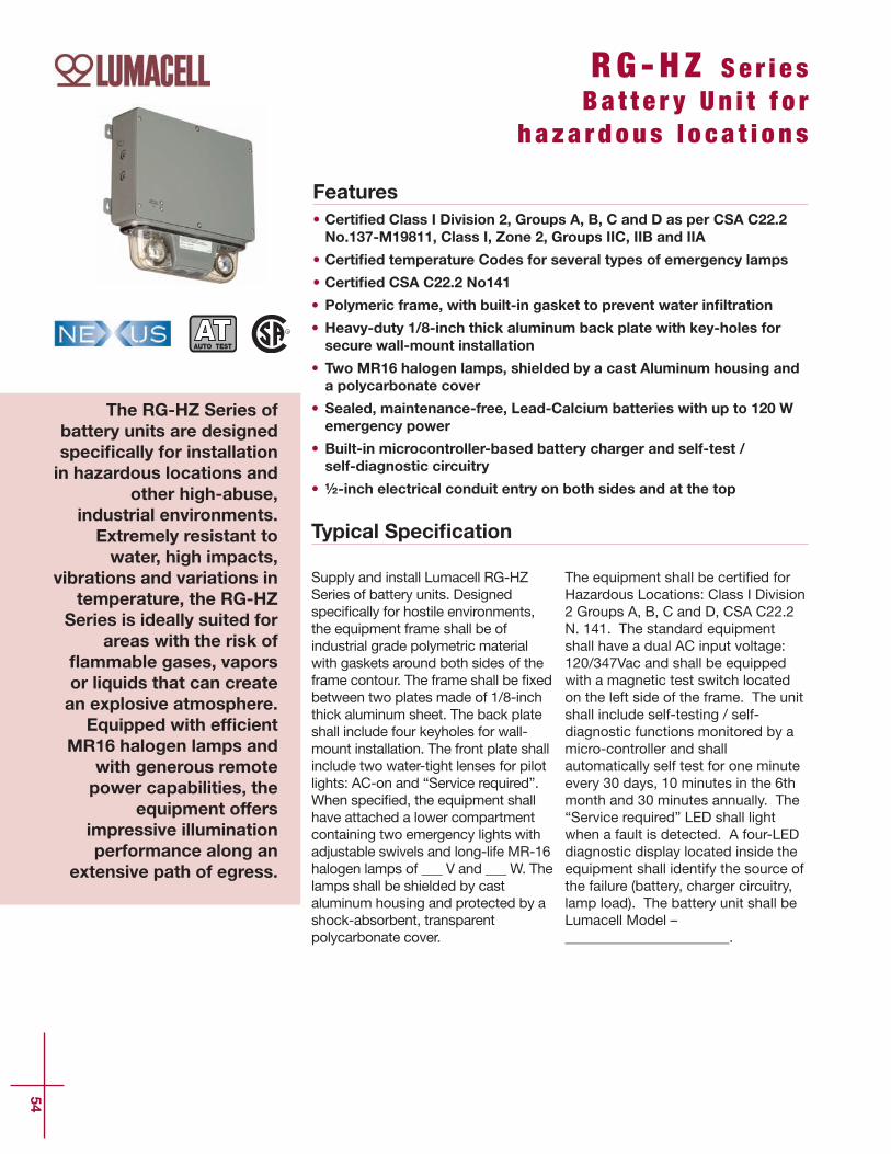
54
Features• Certified Class I Division 2, Groups A, B, C and D as per CSA C22.2No.137-M19811, Class I, Zone 2, Groups IIC, IIB and IIA
• Certified temperature Codes for several types of emergency lamps
• Certified CSA C22.2 No141
• Polymeric frame, with built-in gasket to prevent water infiltration
• Heavy-duty 1/8-inch thick aluminum back plate with key-holes forsecure wall-mount installation
• Two MR16 halogen lamps, shielded by a cast Aluminum housing anda polycarbonate cover
• Sealed, maintenance-free, Lead-Calcium batteries with up to 120 Wemergency power
• Built-in microcontroller-based battery charger and self-test / self-diagnostic circuitry
• ½-inch electrical conduit entry on both sides and at the top
Typical Specification
RG -HZ Se r i e sBa t t e r y U n i t f o r
h a z a r d ou s l o c a t i o n s
The RG-HZ Series ofbattery units are designedspecifically for installationin hazardous locations and
other high-abuse,industrial environments.Extremely resistant towater, high impacts,
vibrations and variations intemperature, the RG-HZ
Series is ideally suited forareas with the risk of
flammable gases, vaporsor liquids that can createan explosive atmosphere.Equipped with efficient
MR16 halogen lamps andwith generous remotepower capabilities, the
equipment offersimpressive illuminationperformance along an
extensive path of egress.
Supply and install Lumacell RG-HZSeries of battery units. Designedspeci_cally for hostile environments,the equipment frame shall be ofindustrial grade polymetric materialwith gaskets around both sides of theframe contour. The frame shall be _xedbetween two plates made of 1/8-inchthick aluminum sheet. The back plateshall include four keyholes for wall-mount installation. The front plate shallinclude two water-tight lenses for pilotlights: AC-on and “Service required”.When speci_ed, the equipment shallhave attached a lower compartmentcontaining two emergency lights withadjustable swivels and long-life MR-16halogen lamps of ___ V and ___ W. Thelamps shall be shielded by castaluminum housing and protected by ashock-absorbent, transparentpolycarbonate cover.
The equipment shall be certi_ed forHazardous Locations: Class I Division2 Groups A, B, C and D, CSA C22.2N. 141. The standard equipmentshall have a dual AC input voltage:120/347Vac and shall be equippedwith a magnetic test switch locatedon the left side of the frame. The unitshall include self-testing / self-diagnostic functions monitored by amicro-controller and shallautomatically self test for one minuteevery 30 days, 10 minutes in the 6thmonth and 30 minutes annually. The“Service required” LED shall lightwhen a fault is detected. A four-LEDdiagnostic display located inside theequipment shall identify the source ofthe failure (battery, charger circuitry,lamp load). The battery unit shall beLumacell Model –_______________________.
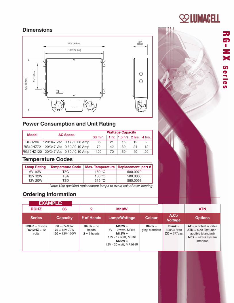
RG-N
X S
erie
s
Dimensions
Model AC SpecsWattage Capacity
30 min. 1 hr. 1.5 hrs. 2 hrs. 4 hrs.RGHZ36 120/347 Vac 0.17 / 0.06 Amp 36 21 15 12 -RG12HZ72 120/347 Vac 0.30 / 0.10 Amp 72 42 30 24 12RG12HZ120 120/347 Vac 0.30 / 0.10 Amp 120 70 50 40 20
Lamp Rating Temperature Code Max. Temperature Replacement part #6V 10W T3C 160 °C 580.007912V 12W T3A 180 °C 580.008012V 20W T2D 215 °C 580.0068
Ordering Information
Power Consumption and Unit Rating
Temperature Codes
Note: Use qualified replacement lamps to avoid risk of over-heating
RGHZ 36 2 M10W ATN
Series Capacity # of Heads Lamp/Wattage Colour A.C./Voltage
Options
RGHZ = 6 voltsRG12HZ = 12
volts
36 = 6V-36W72 = 12V-72W120 = 12V-120W
Blank = noheads
2 = 2 heads
M10W =6V - 10 watt, MR16
M12W =12V - 12 watt, MR16
M20W =12V - 20 watt, MR16-IR
Blank =grey, standard
Blank =120/347vacZC = 277vac
AT = autotest audibleATN = auto Test ,non-audible (standard)
NEX = nexus systeminterface
EXAMPLE:
141/2” [36.8cm]31/2”
[8.9cm]
133/4” [34.9cm]
125 /8 ”
[32.
1cm
]
61 /4 ” [1
5.6c
m]

56
Features• IP65 rated for wet and damp locations
• Polycarbonate enclosure and lens, vandal resistant and UV stabilizedRust proof hardware
• Ceiling, surface or pendant mounting
• Low profile, less than 4” deep
• Ultra efficient specular reflector with optimized shape
• 32W T8 or 54W T5HO
• 90 minutes of emergency operation when installed with our RSFSP orAM inverters
• Emergency operation from external DC power source when installedwith our RSF Series inverters
• High efficiency and reliable electronic ballast, instant start or 3-stepprogrammed rapid start
• 120Vac to 277Vac universal and 347Vac input voltage available
• CSA certified to CAN/CSA-E60598-1:02
Typical Specification
I P L T M S e r i e sI P 65 L i n e a r
F l u o r e s c e n t F i x t u r e
The IPLTM Series offluorescent fixtures byLumacell are offered asnormally on standard
linear fluorescent fixtures.When used with one of ourfluorescent inverters, the
IPLTM is converted to aself-powered emergencylighting unit. Suitable fordamp or wet location, the
IPLTM, thanks to itspolycarbonate enclosureand lens as well as therustproof hardware, istruly a durable fixture.
Supply and install Lumacell IPLTM
Series of fluorescent fixtures asspecified. The luminaire shalloperate from 120Vac to 277Vac or347Vac and use high quality instantstart or 3-step programmed rapidstart high efficiency electronicballasts.
The body and lens shall beconstructed of UV stabilizedindustrial grade vandal resistantpolycarbonate. A durable formedgasket shall be provided betweenthe enclosure and the lens andshall be designed specifically forhostile environments. The reflectorshall be made of highly specularmaterial and formed to maximizelight output efficiency. All partsshall be corrosion resistant. Ametal plate used to retain theballast and reflector also serves todissipate heat, thereforelengthening ballast life.
Lamps shall be as speci_ed, either T8or T5 HO linear `uorescent lamps, 32Wor 54W. The lamps shall not besupplied with the luminaire. Modelswith an inverter from the RSFSP/AMseries and illuminate one or two lampsduring emergency operation for at least90 minutes upon AC failure. Duringpower outage, dual voltage source(AC/DC) models with an inverter fromthe RSF series, shall illuminate onelamp while the DC voltage is present.
The _xture shall be CSA approvedand meet IP65 requirements.
The inverters of RSF series shall beCSA approved.
The inverters of the RSFSP/AM seriesshall be CSA or cUL approved.
The _xture shall be Lumacell Model:IPL __________________
Sturdy construction, easy installation,wet location fluorescent fixture
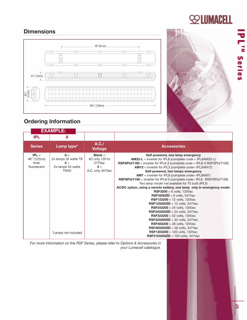
IPL
TMSerie
s
57
36” [91cm]
33/4” [10cm]
503/4” [129cm]
63 / 4”[1
7cm
]
Dimensions
Ordering Information
IPL 8
Series Lamp type*A.C./Voltage
Accessories
IPL =48" (122cm)
linier`uorescent
8 = 2x lamps 32 watts T8
5 = 2x lamps 54 watts
T5HO
*Lamps not included
Blank = AC only 120 to
277Vac3 =
A.C. only 347Vac
Self-powered, one lamp emergencyAM32-L = inverter for IPL8 (complete code = IPL8AM32-L)
RSFSP⁄U⁄1100 = inverter for IPL8-3 (complete code = IPL8-3 RSFSP⁄U⁄1100)AM12 = inverter for IPL5 (complete code= IPL5AM12)
Self-powered, two lamps emergencyAM7 = inverter for IPL8 (complete code= IPL8AM7)
RSFSP⁄U⁄1100 = inverter for IPL8-3 (complete code= IPL8- 3RSFSP⁄U⁄1100)Two lamp model not available for T5 bulb (IPL5)
AC⁄DC option, using a remote battery, one lamp only in emergency mode:RSF3200 = 6 volts, 120Vac
RSF3200ZD = 6 volts, 347VacRSF123200 = 12 volts, 120Vac
RSF123200ZD = 12 volts, 347VacRSF243200 = 24 volts, 120Vac
RSF243200ZD = 24 volts, 347VacRSF323200 = 32 volts, 120Vac
RSF323200ZD = 32 volts, 347VacRSF483200 = 48 volts, 120Vac
RSF483200ZD = 48 volts, 347VacRSF1203200 = 120 volts, 120Vac
RSF2103200ZD = 120 volts, 347Vac
EXAMPLE:
For more information on the RSF Series, please refer to Options & Accessories inyour Lumacell catalogue.


CATALOG
Optio
ns &
Acessorie
s

60
In an existing or new installation where exit signs andemergency lighting may be supplied by a single 120VDC sourceusing a common negative wire and a switched positive.3 wire output from the system reduces the number ofconductors by up to 40%. It also eliminates 50% of the conduit,EMT or BX runs by using a single common conduit for LEDexits and emergency lighting remotes.
LumaSource SeriesTime and labour saveronly one conduit required!
Features
• Single-source 120 VDC supplyfor both exit and emergencylights
• Reduced number of conductors• Eliminates 50% of conduit, BXor EMT runs for exit andemergency lighting
• Control and supervisionfunctions on single modularboard
• Complete package of fullsupervisory functions andalarms included in standard unit
• Floor-mount cabinet• Battery is sealed maintenancefree lead calcium
• All LumaSource Series systemsare designed and manufacturedin Canada
• CSA and Ontario Hydroapproved
• BMEC (Building MaterialsEvaluation Commission)approved for compliance to theOntario Building Code
• Overall reduction on powerconsumption using LED exitsigns
• 120 VDC Central Single SourceEmergency Lighting System
OperationsLumaSource Series CentralEmergency LightingSystems are available in free-standing cabinetstyle enclosures.• Heavy duty, sheet-steel cabinet.• Cabinets are painted ASA No. 61 greyelectrolyte resistant enamel.• Locking and hinged front door.• Front access to battery charger forease of inspection and servicing.
• Generous ventilation provided
Charger / ControlsLumacell’s solid state fully automaticcharger features single modulecontrol board design. This featureprovides cost effective superiorperforming equipment, with ease ofmaintenance and serviceability.
Standard Features andControls• LVD at 91% of nominal Batteryvoltage
• Temperature Compensation• Ground Fault Alarm (Audible &Visual)
• DC Volt & Ammeter (2% Accuracy)• AC present LED indicator• Float level Charge LED indicator• Equalize level Charge LEDindicator
• Charger Failure Alarm• AC Failure Alarm• High Battery Voltage Alarm• Test Switch• Remote Monitor Alarm Panel• Brownout Protection• Dry Contacts
• BMEC - Ontario Building MaterialsEvaluation Commission Approved
• SPF - sprinkler-proof cabinetcomes with drip shield
Optional Features Code• Time Delay TD• 3 Phase Sensing 3PH• 12 Hour Recharge 12HR• 30 or 90 day equalize cycle CYC30 (90)
ApplicationNew construction or retro-_t, theLumaSource Series utilizes the latesttechnology and engineering toreduce the cost of emergencylighting installations. The unique 3wire design allows for the use of justone conduit. With one positive dcnormally energized conductor and acommon negative conductor the LEDexits are supplied constant power.With the same common negativeconductor and a switched positivedc conductor the remote emergencylights are powered on demand.Available in sizes from 4120 watts to22520 watts for 30 minutes.
ElectricalInput: 120V, 240V, 347V, 600V AC60HZ Single Phase Output: 120V DC (3 wire unswitchedpositive, common and switchedpositive)) Systems have beendesigned for minimum 1/2 houroperation time and are capable offull recharge in 24 hours.For systems rating chart andordering guide please see Page 63.Other discharge times are availableupon request.

61
Canada. Limit room ambienttemperature between 0oC to35oC (32oF to 95oF).Optimum systemperformance occurs at 25oC(77oF). A battery service lifeis de_ned as the periodwhich the battery could still provideat least 80% of its rated capacity.
Approvals• CSA Certi_ed• Ontario Hydro: Rule 46-108 (3)
WarrantyThe complete system is guaranteedfor a period of one (1) year againstdefects in workmanship andmaterials. The battery portion of theequipament carries a ten (10) yearpro-rata warranty during its usefulservice life against defects inworkmanship and materials. Thebattery warranty is subject to theprovision of normal testing andinspection as speci_ed in theCanadian Electrical Code, Section46-102, and National Fire Code of
LumaSource Series
Typical Interconnection Wiring Diagram
Develop a Model Number as shown in the following chart
(1)System
Designation
(2)SinglePhase
(3)BatteryType
(4)Capacityin Watts
(5)Qty of
Exit Signs
(6)Mounting
(7)OutputVoltage
(8)DischargeTime
(Minutes)
(9)OptionalEquipment
LS4 120Vac240Vac347Vac600Vac
SL
SealedLead
Calcium
41206400939011260131401878022520
50E100E
C = Console 120V DC 30
For other
discharge
times please
contact factory
TD3PH12HRCYC30CYC90
Enclosure DimensionsSystemSeries
ConsoleH x W x D
LS4 4120LS4 6400-11260LS4 13140-22520
38” x 38” x 18”38” x 38” x 28”56” x 38” x 28”
Time and labour saveronly one conduit required!
CAD Drawing illustrateshow the LumaSourceSeries is applied,saving time, materialand money.Call your local LumacellRepresentative forfurther information, orapplication assistance.
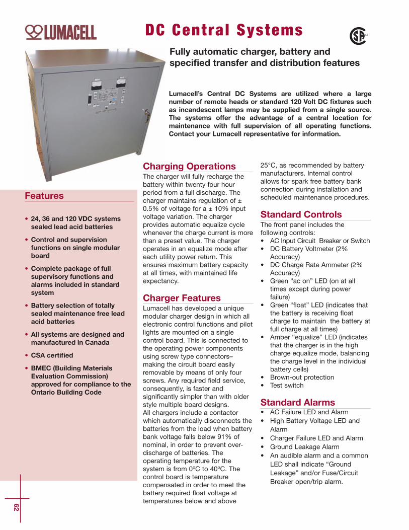
Lumacell’s Central DC Systems are utilized where a largenumber of remote heads or standard 120 Volt DC fixtures suchas incandescent lamps may be supplied from a single source.The systems offer the advantage of a central location formaintenance with full supervision of all operating functions.Contact your Lumacell representative for information.
DC Central SystemsFully automatic charger, battery andspecified transfer and distribution features
62
Features
• 24, 36 and 120 VDC systemssealed lead acid batteries
• Control and supervisionfunctions on single modularboard
• Complete package of fullsupervisory functions andalarms included in standardsystem
• Battery selection of totallysealed maintenance free leadacid batteries
• All systems are designed andmanufactured in Canada
• CSA certified
• BMEC (Building MaterialsEvaluation Commission)approved for compliance to theOntario Building Code
Charging OperationsThe charger will fully recharge thebattery within twenty four hourperiod from a full discharge. Thecharger maintains regulation of ±0.5% of voltage for a ± 10% inputvoltage variation. The chargerprovides automatic equalize cyclewhenever the charge current is morethan a preset value. The chargeroperates in an equalize mode aftereach utility power return. Thisensures maximum battery capacityat all times, with maintained lifeexpectancy.
Charger FeaturesLumacell has developed a uniquemodular charger design in which allelectronic control functions and pilotlights are mounted on a singlecontrol board. This is connected tothe operating power componentsusing screw type connectors–making the circuit board easilyremovable by means of only fourscrews. Any required _eld service,consequently, is faster andsigni_cantly simpler than with olderstyle multiple board designs.All chargers include a contactorwhich automatically disconnects thebatteries from the load when batterybank voltage falls below 91% ofnominal, in order to prevent over-discharge of batteries. Theoperating temperature for thesystem is from 0ºC to 40ºC. Thecontrol board is temperaturecompensated in order to meet thebattery required `oat voltage attemperatures below and above
25°C, as recommended by batterymanufacturers. Internal controlallows for spark free battery bankconnection during installation andscheduled maintenance procedures.
Standard ControlsThe front panel includes thefollowing controls:• AC Input Circuit Breaker or Switch• DC Battery Voltmeter (2%
Accuracy)• DC Charge Rate Ammeter (2%
Accuracy)• Green “ac on” LED (on at all
times except during powerfailure)
• Green “`oat” LED (indicates thatthe battery is receiving `oatcharge to maintain the battery atfull charge at all times)
• Amber “equalize” LED (indicatesthat the charger is in the highcharge equalize mode, balancingthe charge level in the individualbattery cells)
• Brown-out protection• Test switch
Standard Alarms • AC Failure LED and Alarm• High Battery Voltage LED and
Alarm• Charger Failure LED and Alarm• Ground Leakage Alarm• An audible alarm and a common
LED shall indicate “GroundLeakage” and/or Fuse/CircuitBreaker open/trip alarm.

DC Cen
tral System
s
63
Other Options
Optional Alarms• Fuse/Circuit Breaker Open/Trip
Alarm
BatteriesSealed Maintenance-Free LeadAcid Gas Recombination (SL Series)Uses gas recombination to eliminatethe escape of hydrogen. Thickplates are constructed of highstrength material which resistsshedding, `aking, or mechanicalfailure. Design Life; 10 years undernormal operating conditions.
Transfer OptionsSystem may be selected to eitherturn on a normally “off” load oralternatively on 120 Volt DCsystems, maintain a normally“on”load.Normally “off” (DC load): (TPD)If the lamp load is going to be turnedon in the event of power failure addsuf_x –TPD to the model number.Normally “on” (AC/DC load): (TPA)120 V DC systems only:The 120 V incandescent load shallhave 120 VAC power normallysupplied to it and the load shall betransferred to 120 VDC upon failure.Add suf_x –TPA to the modelnumber. For other AC input voltagesplease contact factory.Both Normally “on” & “off” loads:(TPA/TPD) Both of the above apply.
Distribution OptionsA separate distribution panel isavailable for all systems.A choice of fuses or circuit breakersis available.Fuse Distribution PanelSelect -DPF ( ) for separatedistribution fuse panel.Select -DPFF ( ) for separatedistribution fuse panel with visualand audible alarm on main consolefor failure of any fuse.Note: “( )” indicates the number of circuitsrequired.
Circuit Breaker Distribution PanelSpecify - DPCB ( ) for separatecircuit breaker panel.Specify - DPCAB ( ) for separatecircuit breaker panel with visual andaudible alarm on main console fortripping or opening of any breaker.Note: “( )” indicates the number of circuitsrequired.
* Zone explanation: each speci_ed zone relay monitors an individual lighting circuit in abuilding. Should any or all of the monitored circuits lose AC power, the connected lightingload will automatically illuminate:a - all zones if ZSC is speci_ed b - that zone only if ZSI is speci_ed
CODE DESCRIPTION
-TD( ) Time delay, specify time, 1–10 minutes-RRAP Recessed remote alarm panel-3PH 3 phase sensing-ZSC( )* Common Zone Sensing-ZSI( )* Individual zone sensing, specify number of zones (external panel)-SPF Sprinkler proof cabinet c/w drip shield-CYC 30 (90) Monthly/yearly auto test-BCB Input battery circuit breaker
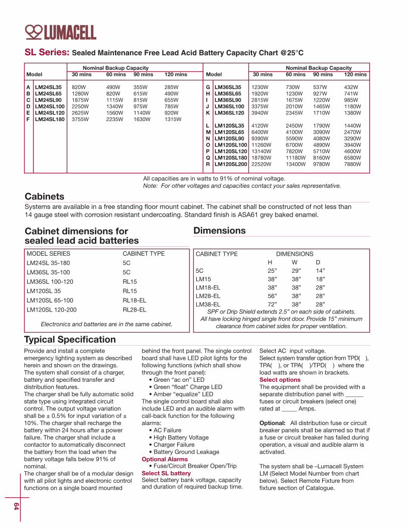
64
SL Series: Sealed Maintenance Free Lead Acid Battery Capacity Chart @25°C
Cabinet dimensions forsealed lead acid batteries
Nominal Backup CapacityModel 30 mins 60 mins 90 mins 120 mins
A LM24SL35 820W 490W 355W 285WB LM24SL65 1280W 820W 615W 490WC LM24SL90 1875W 1115W 815W 655WD LM24SL100 2250W 1340W 975W 785WE LM24SL120 2625W 1560W 1140W 920WF LM24SL180 3755W 2235W 1630W 1315W
Nominal Backup CapacityModel 30 mins 60 mins 90 mins 120 mins
G LM36SL35 1230W 730W 537W 432WH LM36SL65 1920W 1230W 927W 741WI LM36SL90 2815W 1675W 1220W 985WJ LM36SL100 3375W 2010W 1465W 1180WK LM36SL120 3940W 2345W 1710W 1380W
L LM120SL35 4120W 2450W 1790W 1440WM LM120SL65 6400W 4100W 3090W 2470WN LM120SL90 9390W 5590W 4080W 3290WO LM120SL100 11260W 6700W 4890W 3940WP LM120SL120 13140W 7820W 5710W 4600WQ LM120SL180 18780W 11180W 8160W 6580WR LM120SL200 22520W 13400W 9780W 7880W
MODEL SERIES CABINET TYPE
LM24SL 35-180 5C
LM36SL 35-100 5C
LM36SL 100-120 RL15
LM120SL 35 RL15
LM120SL 65-100 RL18-EL
LM120SL 120-200 RL28-EL
Electronics and batteries are in the same cabinet.
CABINET TYPE DIMENSIONSH W D
5C 25” 29” 14”LM15 38” 38” 18”LM18-EL 38” 38” 28”LM28-EL 56” 38” 28”LM38-EL 72” 38” 28”
SPF or Drip Shield extends 2.5” on each side of cabinets.All have locking hinged single front door. Provide 15” minimum
clearance from cabinet sides for proper ventilation.
All capacities are in watts to 91% of nominal voltage.Note: For other voltages and capacities contact your sales representative.
CabinetsSystems are available in a free standing `oor mount cabinet. The cabinet shall be constructed of not less than 14 gauge steel with corrosion resistant undercoating. Standard _nish is ASA61 grey baked enamel.
Typical Specification
Dimensions
Provide and install a completeemergency lighting system as describedherein and shown on the drawings.The system shall consist of a charger,battery and speci_ed transfer anddistribution features.The charger shall be fully automatic solidstate type using integrated circuitcontrol. The output voltage variationshall be ± 0.5% for input variation of ±10%. The charger shall recharge thebattery within 24 hours after a powerfailure. The charger shall include acontactor to automatically disconnectthe battery from the load when thebattery voltage falls below 91% ofnominal.The charger shall be of a modular designwith all pilot lights and electronic controlfunctions on a single board mounted
behind the front panel. The single controlboard shall have LED pilot lights for thefollowing functions (which shall showthrough the front panel): • Green “ac on” LED • Green “`oat” Charge LED • Amber “equalize” LED
The single control board shall alsoinclude LED and an audible alarm withcall-back function for the followingalarms:• AC Failure• High Battery Voltage• Charger Failure• Battery Ground Leakage
Optional Alarms• Fuse/Circuit Breaker Open/Trip
Select SL batterySelect battery bank voltage, capacityand duration of required backup time.
Select AC input voltage.Select system transfer option from TPD( ),TPA( ), or TPA( )/TPD( ) where theload watts are shown in brackets.Select optionsThe equipment shall be provided with aseparate distribution panel with ______fuses or circuit breakers (select one)rated at _____ Amps.
Optional: All distribution fuse or circuitbreaker panels shall be alarmed so that ifa fuse or circuit breaker has failed duringoperation, a visual and audible alarm isactivated.
The system shall be –Lumacell SystemLM (Select Model Number from chartbelow). Select Remote Fixture from_xture section of Catalogue.

Standard Features
65
CODE DESCRIPTIONGL Ground leakage.FC One set of dry contacts for remote fault sensing.RAP Remote alarm panel.SPF Drip shield (2.5” overhang on console).BRO Brownout.BMEC Ontario Building Materials Evaluation Commission approved.
Product Code Construction
Warranty The complete system is guaranteed for a period of one (1) year againstdefects in workmanship and materials. The battery portion of theequipament carries a ten (10) year pro-rata warranty during its usefulservice life against defects in workmanship and materials. The batterywarranty is subject to the provision of normal testing and inspection asspeci_ed in the Canadian Electrical Code, Section 46-102, and NationalFire Code of Canada. Limit room ambient temperature between 0oC to35oC (32oF to 95oF). Optimum system performance occurs at 25oC (77oF). Abattery service life is de_ned as the period which the battery could stillprovide at least 80% of its rated capacity.
LMLumacell Designation
DC VoltageA 24
B 36
C 120Battery TypeBlank = SL
CapacitySelect from Battery Capacity chart in
folderOperating Time (minutes)
30
60
90
120
180
240
AC Voltage (Vac)A 120
B 208
C 240
D 277
E 347
F 480
G 600
Transfer OptionsSpecify Watts for each typeof load
TPD( )
TPA( )
TPA( )/TPD( )
Distribution OptionsSpecify number of circuits
DPF( )
DPFF( )
DPCB( )
DPCAB( )Other OptionsSpecify no.of zones sensing
ZSC( )
ZSI( )
TD( )
BCB
3PH
Specify time
CYC 30
CYC 90
From the selections of features in theSPECIFICATION GUIDE construct theModel Number as shown above.

66
VSR Se r i e s
Typical VSR-4(120)-1(120)-EXT Wiring
Typical Specification
OperationThe VSR (Voltage Sensing
Relay) option activates all ofthe emergency lighting ifonly one, multiple or all
zones become de-energizedthrough either a powerfailure or lighting circuit
breaker tripping.This greatly enhances thelife safety system, as anyfailure of a lighting circuit
will ensure emergencyegress lighting.
A separate test button foreach zone enables
individual testing of eachcircuit monitored. The VSR
can be specified to bemanufactured within a
battery pack or in its ownseparate enclosure.
Zone Sensing Option
Each battery pack shall beprovided with either internally orexternally, zone sensing relays.These relays shall be pre-wired bythe factory within the battery packor pre-wired in their own enclosure.Each zone shall have it's own'push to test' push button mountedon the side of the battery pack orin the case of a separateenclosure, on the enclosure door.Each zone push button shall be
clearly identified to thecorresponding branch lighting orexit circuit being monitored.Provide a minimum of two (2) sparezone circuits for future use. Thezone sensing panel shall be equalto that of a Lumacell model VSR-(number of zones)-(ac voltage ofzones)-(number of unit equipmentper VSR panel)-(ac voltage of unitequipment)-(class of enclosure), ie:VSR-4(120)-1(120)-EXT

67
VSR S
erie
s
Ordering Information
e.g.VSR - 5 (347) - 1(120) -INT
SeriesAC voltage of
zones AC voltageof Packs
Cabinet OtherOptions
e. g. VSR
# of ccts (zones)or lighting panels
monitored
120240277347
# of Battery PacksServed
120240277347
-INT = VSR supplied in battery pack enclosure
-EXT =VSR supplied in its own EEMAC 1 enclosure
-EXT-DT =VSR supplied in its own EEMAC 12 (Dust Tight)
enclosure-EXT-DTF =
VSR supplied in its own EEMAC 4 enclosure-EXT-XP =
VSR supplied in its own Classi_ed Area Use enclosure(class, division & group must be speci_ed)
PB = push buttonzone testing
PL = pilot lamp perzone
EXAMPLE:
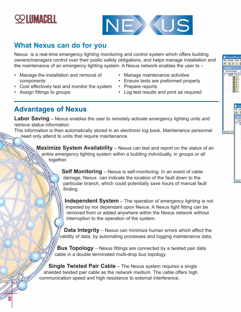
What Nexus can do for youNexus is a real-time emergency lighting monitoring and control system which offers buildingowners/managers control over their public safety obligations, and helps manage installation andthe maintenance of an emergency lighting system. A Nexus network enables the user to –
Advantages of NexusLabor Saving – Nexus enables the user to remotely activate emergency lighting units andretrieve status information.This information is then automatically stored in an electronic log book. Maintenance personnel
need only attend to units that require maintenance.
Maximize System Availability – Nexus can test and report on the status of anentire emergency lighting system within a building individually, in groups or all
together.
Self Monitoring – Nexus is self-monitoring. In an event of cabledamage, Nexus can indicate the location of the fault down to theparticular branch, which could potentially save hours of manual faultfinding
Independent System – The operation of emergency lighting is notimpeded by nor dependant upon Nexus. A Nexus light fitting can beremoved from or added anywhere within the Nexus network withoutinterruption to the operation of the system.
Data Integrity – Nexus can minimize human errors which affect thevalidity of data, by automating processes and logging maintenance data.
Bus Topology – Nexus fittings are connected by a twisted pair datacable in a double terminated multi-drop bus topology.
Single Twisted Pair Cable – The Nexus system requires a singleshielded twisted pair cable as the network medium. The cable offers high
communication speed and high resistance to external interference.
68
• Manage the installation and removal ofcomponents
• Cost effectively test and monitor the system• Assign fittings to groups
• Manage maintenance activities• Ensure tests are preformed properly • Prepare reports• Log test results and print as required

69
Easy to use Graphic User Interface – The Nexus softwarecontains an easy to use graphic user interface which guidesthe user through a series of functions
Nexus Warranty – Lumacell emergency lighting equipmentunits with the Nexus options are fully warranted to be free ofdefects in material and workmanship under normal use for aperiod of five (5) years. The full warranty period begins on thedate of installation or ninety (90) days from the date ofshipment, whichever date is earlier.
Wherever you are, you can depend onto get the job done!
For more information please contact us at:1-866-857-5711 (ext. 7515)[email protected]
Example of Nexus screens.
All information and specifications containedin this catalogue are subject to change dueto engineer design, error and omissions.Illustrations and diagrams within this
catalogue may vary from actual products.
2008 © Thomas & Betts Limited. All rights reserved.
Printed in Canada. 07/08/2000. Order no. LU/INDUSTRIALCAT