industrial communication simatic net - impol-1
TRANSCRIPT
Siemens IK PI News · January 2010
4/2 System interfacing for PG/PC4/2 Overview4/5 CP 56034/11 CP 56234/17 CP 56244/23 CP 5711
4/28 Industrial controls –Motor starters for operation in the field, high degree of protection
Sec.6 SIRIUS M200D motor startersGeneral data
4/28 M200D motor startersfor PROFIBUS / PROFINET
4/32 M200D motor starters for PROFIBUS / PROFINETCommunication modules, motor starter modules
Sec.6 Accessories
4/33 SIRIUS 3RK3 Modular Safety System
4/33 General data4/35 Central modules, expansion modules,
interface modules, operating and monitoring modules
4/36 Accessories4/37 Software
Modular Safety System ES
4/40 Power Management System4/40 System overview4/41 SENTRON multifunction measuring
instrumentsGeneral data
4/45 PAC3100 multifunction measuring instruments
4/46 PAC3200 multifunction measuring instruments
4/47 PAC4200 multifunction measuring instruments
4/48 PAC PROFIBUS DP expansion modules4/49 PAC RS485 expansion modules4/50 PAC 4DI/2DO expansion modules
for PAC4200
4/51 Configuring, Visualizing and Controlling with SIMATIC
4/51 SIMATIC PCS 7 powerrate4/53 SIMATIC WinCC powerrate4/55 SIMATIC PCS 7 Library PAC32004/56 3WL/3VL function block library
for SIMATIC PCS 74/57 PAC3200 function block library
for SIMATIC WinCC
4/58 Configuring, Visualizing and Controlling with SENTRON
4/58 Switch ES Power
4/59 SIMATIC FS600 laser scanner4/59 PROFIsafe laser scanner
PROFIBUS
Kap_04_Titel_en.fm Seite 1 Freitag, 29. Januar 2010 9:53 09
© Siemens AG 2010

PROFIBUSSystem interfacing for PG/PC
Overview
4/2 Siemens IK PI News · January 2010
4
■ Communications processors for PG/PC
System connections for PG/PC
PC card with an internal microprocessor
Recommended solution for:• PC-based control systems
(Soft Control, PLC, Numeric Control, Robot Control)• Process control systems• Operator control and monitoring systems (HMI)• PROFIBUS DP slave connection (CP 5614 A2)• PROFIBUS plants with large quantity framework
(more than 8 stations)• Multi-protocol operation• Use of several CPs in one system• Designs with fiber-optic interface (FO)
PC card without an internal microprocessor
Recommended solution for:• Configuring tools (e.g. STEP 7)• PROFIBUS DP diagnostics station
(e.g. with COM PROFIBUS or as DP master Class 2)• PROFIBUS DP slave connection• PROFIBUS plants with up to 8 stations• Mono protocol mode
You will find software for the PC products running under Windowswith the corresponding authorization diskettes on the SIMATIC NET software CD.Development Kits are available for use in various operating system environments (e.g. for CP 5613 A2 or CP 5614 A2).As a rule, the necessary configuration tools are included in the software packages.Manuals in PDF format and extensive supplementary information on SIMATIC NET products and communication can be found in the SIMATIC NET Manual Collection which is enclosed with the software products.
CPs without an internal microprocessor
CPs with an internal microprocessor
G_I
K10
_XX
_501
84
CP 5512(PC-Card, CardBus)
CP 5613 A2 (PCI)CP 5623(PCIe)
CP 5611 A2 (PCI)CP 5621 (PCIe)
CP 5613 FO (PCI)
CP 5614 A2 (PCI)CP 5624(PCIe)
SIMATIC NETManual Collection
Software Hardware
CP 5711(USB V2.0)
CP 5603
Kap_04_en.fm Seite 2 Freitag, 29. Januar 2010 9:52 09
© Siemens AG 2010

PROFIBUSSystem interfacing for PG/PC
Overview
4/3Siemens IK PI News · January 2010
4
■ Communication overview for PG/PC
Communication overwiew for PG/PC
DP-5613 4)
S7-5613
Kap_04_en.fm Seite 3 Freitag, 29. Januar 2010 9:52 09
© Siemens AG 2010

PROFIBUSSystem interfacing for PG/PC
Overview
4/4 Siemens IK PI News · January 2010
4
■ Communication overview for SIMATIC PCs
The operating systems listed in the table refer exclusively to the communication products specified!
Please refer to the description of the relevant IPC for the operat-ing system that is available and has been released for that IPC.
Options for connecting PROFIBUS CPs to PG/PC
Embedded Systems
Communi-cation hardware
Communication hardware
Operating system envi-ronment of the communi-cation software
SIMATIC Industrial PC/Field PG
Op.sys.
SIMATIC Industrial PCs 4)
Win
dow
s X
P P
ro +
SP
2/3
Win
dow
s S
erve
r 200
3 R
2 / S
P2
Win
dow
s S
erve
r 200
8
Vis
ta B
usin
ess
/ Ulti
mat
e +
SP
1
othe
r ope
ratin
g sy
stem
s
Fiel
d P
G M
Rac
k P
C 8
47B
Rac
k P
C 6
47B
Rac
k P
C 5
47B
/ 54
7C,
Pan
el P
C 5
77B
/ 57
7C
Box
PC
627
B
Box
PC
827
B
Mic
robo
x 42
7B /
427C
(w
ith C
P 5
603)
Win
dow
s X
Pem
bedd
ed +
S
P1/
SP
2/FP
200
7 (w
ith C
P 5
603)
Mic
robo
x 42
7B /
427C
(w
ith C
P 5
603)
Pan
el P
C 4
77B
/ 47
7C
(with
CP
560
3)
Pan
el P
C 6
77B
/ 67
7C 4
)
Box
PC
627
B
SIM
ATIC
S7
mod
ular
Em
bedd
ed
Con
trolle
r
CPs and software for Industrial Ethernet
CP 5603(PCI-104)
CP with DP-Base • - - - - - - - - - - • • • • - - -DK-5613 1) (DP-base) ○ - - - ○ - - - - - - ○ ○ ○ ○ - - ○DP-5613 • - - - - - - - - - - • • • • - - -S7-5613 • - - - - - - - - - - • • • • - - -
CP 5613 A2CP 5613 FOCP 5614 A2(PCI 32 Bit)
CP with DP-Base • • • • - - • • • • • - - - - • • -DK-5613 1) (DP-base) ○ ○ ○ ○ ○ - ○ ○ ○ ○ ○ - ○ - - ○ ○ -DP-5613 • • • • - - • ○ • • • - - - - • • -S7-5613 • • • • - - • ○ • • • - - - - • • -FMS-5613 • • • • - - • ○ • • • - - - - • • -
CP 5623 CP 5624 (PCIe x1)
CP with DP-Base • • • • - - ○5) • • ○5) ○5) - - - - ○5) ○5) -DK-5613 1) (DP-base) ○ ○ ○ ○ ○ - ○5) ○ ○ ○5) ○5) - ○ - - ○5) ○5) -DP-5613 • • • • - - ○5) • • ○5) ○5) - - - - ○5) ○5) -S7-5613 • • • • - - ○5) • • ○5) ○5) - - - - ○5) ○5) -
CP 5611 A2(PCI 32 Bit)
SOFTNET-DP • • • • - - • • • • • - - - - • • -SOFTNET-DP Slave • • • • - - • • • • • - - - - • • -SOFTNET-S7 • • • • - - • • • • • - - - - • • -
CP 5621(PCIe x1)
SOFTNET-DP • • • • - • ○5) • • ○5) ○5) - - - - ○5) ○5) -SOFTNET-DP Slave • • • • - • ○5) • • ○5) ○5) - - - - ○5) ○5) -SOFTNET-S7 • • • • - • ○5) • • ○5) ○5) - - - - ○5) ○5) -
CP 5512(Cardbus 32 Bit)
SOFTNET-DP • • • • - • - - - - - - - - - - - -SOFTNET-DP Slave • • • • - • - - - - - - - - - - - -SOFTNET-S7 • • • • - • - - - - - - - - - - - -
CP 5711 (USB V2.0)
SOFTNET-DP • • • • - • • • • • • • • • • • • -SOFTNET-DP Slave • • • • - • • • • • • • • • • • • -SOFTNET-S7 • • • • - • • • • • • • • • • • • -
SIMATIC PG/PCwith integralPROFIBUSinterface
SOFTNET-DP • • - • - • - - - • • ○4) • ○4) • • • -SOFTNET-DP Slave • • - • - • - - - • • ○4) • ○4) • • • -SOFTNET-S7 • • - • - • - - - • • ○4) • ○5) • • • -
1) Use of these CPs in other operating system environments re-quires porting of the DK-5613 Development Kit to the relevant operating system environment. You can order the DK-5613 in the Internet under www.siemens.com/simatic-net/dk5613.
2) Integrated PROFIBUS interface is optional3) Possible with restrictions, if necessary, depending on memory
expansion and processor capacity. 4) Not possible for 677B/677C in version with 1x PCI or
1x PCIe slot5) Depending on the slots of the selected PC version6) EM-PCI 104 expansion module required
Notes- Please always note the supplementary conditions for the specified SIMATIC NET products
that you can view in the Internet pages shown below.- for further details on XP embedded, see
http://support.automation.siemens.com/WW/view/de/ 21661049- further details on system requirements and operating environments can be found in the
Readme file of the communication products on the SIMATIC NET PC Software CD, 2008 SP2 Edition or under http://support.automation.siemens.com/WW/view/de/ 26610954
- Updates and supplements to the catalog entries, as well as the above tables can be viewed under http://www.siemens.com/simatic-net/ik-info
•-○
suitable
not suitable
suitable under certain conditions
on SIMATIC NET CD 2008 SP2 Edition G
_IK1
0_XX
_50025
Kap_04_en.fm Seite 4 Freitag, 29. Januar 2010 9:52 09
© Siemens AG 2010

PROFIBUSSystem interfacing for PG/PC
CP 5603
4/5Siemens IK PI News · January 2010
4
■ Overview
• PCI-104 interface card with own microprocessor for connect-ing embedded systems with PCI-104 interface to PROFIBUS at up to 12 Mbit/s
• Function compatible with CP 5613 A2• Communication services:
- PROFIBUS DP Master Class 1 and 2 or DP slave according to IEC 61158/61784
- PG/OP communication with STEP 5 and STEP 7- S7 communication with S7-5613 software package- Open communication (SEND/RECEIVE) based on the FDL
interface- PROFIBUS FMS according to IEC 61158/61784 with
FMS-5613 software package• Extensive diagnostics options for installation, commissioning
and operation of the module• Event and filter mechanism for reducing the load on the host
CPU• Multiprotocol operation and parallel operation of up to three
CPs • The appropriate OPC server and configuration tools are
included in the scope of delivery of the respective communi-cation software
• Linux-based development kit with driver sources for integra-tion into "non-Windows" environments
Note:FMS-5613 supports up to two CP 5603/CP 5613 A2/5614 A2/CP 5623/CP 5624 processors.
■ Benefits
• Fast process data exchange; access to process data by means of direct access to the dual port RAM of the hardware
• High computing performance in the PG/PC; reduces workload of host CPU by preprocessing the commu-nication on the hardware
• Use of different operating system environments; driver as source code for porting to different operating system environments
• Use also in motion control applications; real-time capable data exchange through constant bus cycle time
■ Application
The CP 5603 allows the connection of embedded systems with a PC/104 Plus interface to PROFIBUS.
The CP 5603 also provides high-performance support to control tasks on the embedded system (PC-based Control, Numeric Control, Robot Control).
■ Function
PROFIBUS DP
Access to process data with DP-Base
The CP 5603 is operated as PROFIBUS DP master module that keeps the process image (input/output and diagnostics data) in the dual port RAM (memory area on the CP). The hardware of the CP 5603 independently executes the high-performance ex-change of data with the PROFIBUS slaves. The user accesses the Dual Port RAM directly. The process data of the slaves is always consistent, i.e. the user receives the data of a slave from one and the same DP cycle.
The DP-5613 and DP-Base software cannot be operated in par-allel
Event filter mechanism
The user receives up-to-date data over two access mecha-nisms:• Cyclic polling of the DP slaves (higher loading for host CPU)• Notification by innovative event/filter mode when changing the
input data of a slave (minimum loading for host CPU)
The two alternatives can also be combined. This allows users to optimize the PC to their applications.
The event/filter mechanism can be used additionally for • Notification by means of an interrupt of the diagnostic mes-
sages from slaves• In equidistance mode, signaling by means of interrupt:
- Start DP cycle- End of cyclic data exchange with the DP slaves
Kap_04_en.fm Seite 5 Freitag, 29. Januar 2010 9:52 09
© Siemens AG 2010

PROFIBUSSystem interfacing for PG/PC
CP 5603
4/6 Siemens IK PI News · January 2010
4
■ Function (continued)
FastLogic
FastLogic means that the CP 5603 can react autonomously to as many as 4 plant statuses. This results in a short response time and independence from the host application, e.g. fast shutdown of devices.
DP programming interface
The DP programming interface (DP-Base) of the CP 5603 has the following functionality:• DP-Master Class 1 including acyclic DP expansions• DP-Master Class 2 including acyclic DP expansions • DP slave
The process data is accessed directly via the dual port RAM. The DP RAM interface not only offers fast access as DP master or DP slave, but it is also a basis for porting to other operating system environments (e.g. VXWorks, QNX, RMOS, RTX).
Administrative function calls (initialization and management services, as well as diagnostic functions) are provided through a library (DP_BASE.DLL or DPS_BASE.DLL).
Development Kit DK-5613
The Development Kit DK-5613 offers access to the functions of DP-Master Class 1 including acyclic DP expansions.
The software development kit DK-5613 enables the communi-cations processor CP 5603 to be integrated into any operating system environments. The kit contains the necessary source code, including the descriptions in PDF format, and can be downloaded free of charge from the Internet.
Access to process data with DP-5613
DP-Master Class 1
The CP 5603 operates as a DP-Master Class 1 according to IEC 61158/61784 and processes the data transfer with the dis-tributed stations (DP slaves) completely autonomously. The cen-tral controller exchanges information with the DP slaves (e.g. ET 200S) in a specified, constantly repeating message cycle. The DP programming interface (DPLib.DLL) provides the PC programmer with function calls for data exchange. The DP inter-face also provides the SYNC and FREEZE functions as well as activation and deactivation of slaves.
The DP function expansions relating to Master Class 1 make it possible to perform acyclic read and write functions (DS_READ, DS_WRITE) as well as acknowledgement of alarms (ALARM_ACK) at the same time as processing cyclic data communication. Data that is to be transferred acyclically (e.g. parameterization data) is only rarely changed in comparison to the cyclic measured values, and is transferred at lower priority in parallel with the cyclic high-speed user data transfer. The alarm acknowledgment at the Master safeguards the transmission of the alarms from DP slaves.
The DP-5613 and DP-Base software cannot be operated in parallel.
DP-Master Class 2
In addition to the DP-Master Class 1 services, the CP 5603 (in combination with the DP programming interface) also offers DP-Master Class 2 services according to IEC 61158/61784. Devices of this type (programming devices, configuring de-vices, or operator panels) are used during the commissioning and for configuring the DP system, or for operating the system while it is running (diagnostics). The DP programming interface provides the following services:• Master diagnosis• Slave diagnosis• Reading the input/output of a slave• Reading configuration data• Changing slave address
These extended DP functions include acyclic access to the parameters and measured values of a slave (e.g. field devices of process automation and intelligent HMI devices). This type of slave must be supplied with extensive parameter data during start-up and during normal operation (DS_READ, DS_WRITE).
PROFIBUS DP connection with embedded PC SIMATIC Microbox
Microbox withintegrated CP 5611
and CP 5603
PROFIBUS DPPROFIBUS DP
G_I
K10
_XX
_500
33
ET 200M ET 200pro
ET 200S
Kap_04_en.fm Seite 6 Freitag, 29. Januar 2010 9:52 09
© Siemens AG 2010
PROFIBUSSystem interfacing for PG/PC
CP 5603
4/7Siemens IK PI News · January 2010
4
■ Function (continued)
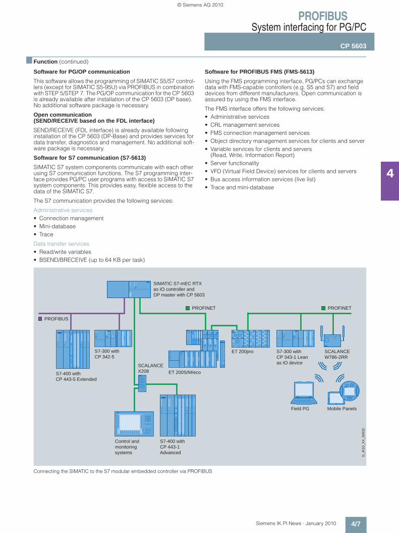
Software for PG/OP communication
This software allows the programming of SIMATIC S5/S7 control-lers (except for SIMATIC S5-95U) via PROFIBUS in combination with STEP 5/STEP 7. The PG/OP communication for the CP 5603 is already available after installation of the CP 5603 (DP base). No additional software package is necessary.
Open communication (SEND/RECEIVE based on the FDL interface)
SEND/RECEIVE (FDL interface) is already available following installation of the CP 5603 (DP-Base) and provides services for data transfer, diagnostics and management. No additional soft-ware package is necessary.
Software for S7 communication (S7-5613)
SIMATIC S7 system components communicate with each other using S7 communication functions. The S7 programming inter-face provides PG/PC user programs with access to SIMATIC S7 system components. This provides easy, flexible access to the data of the SIMATIC S7.
The S7 communication provides the following services:
Administrative services • Connection management• Mini-database• Trace
Data transfer services • Read/write variables• BSEND/BRECEIVE (up to 64 KB per task)
Software for PROFIBUS FMS (FMS-5613)
Using the FMS programming interface, PG/PCs can exchange data with FMS-capable controllers (e.g. S5 and S7) and field devices from different manufacturers. Open communication is assured by using the FMS interface.
The FMS interface offers the following services:• Administrative services• CRL management services• FMS connection management services• Object directory management services for clients and server• Variable services for clients and servers
(Read, Write, Information Report)• Server functionality • VFD (Virtual Field Device) services for clients and servers• Bus access information services (live list)• Trace and mini-database
Connecting the SIMATIC to the S7 modular embedded controller via PROFIBUS
S7-400 withCP 443-5 Extended
S7-400 withCP 443-1Advanced
S7-300 withCP 342-5
S7-300 withCP 343-1 Leanas IO device
SIMATIC S7-mEC RTX as IO controller andDP master with CP 5603
Control and monitoringsystems
PROFINETPROFINET
PROFIBUS
G_I
K10
_XX
_500
32
Mobile PanelsField PG
ET 200pro
ET 200S/M/ecoSCALANCEX208
SCALANCE W786-2RR
Kap_04_en.fm Seite 7 Freitag, 29. Januar 2010 9:52 09
© Siemens AG 2010

PROFIBUSSystem interfacing for PG/PC
CP 5603
4/8 Siemens IK PI News · January 2010
4
■ Function (continued)
User interfaces
OPC interface
The OPC server included in the respective software package can be used as the standard programming interface for the PROFIBUS DP, open communication, S7 communication and PROFIBUS FMS for linking automation technology applications to OPC-capable Windows applications (Office, HMI systems, etc.).
Programming interface via C-Library
The programming interfaces for existing applications are implemented as Dynamic Link Libraries (DLL). The released compilers can be found in the readme file of the SIMATIC NET CD products at http://www.siemens.com/automation/csi/net.
For Borland programming interfaces (e.g. DELPHI), partner solutions from the company SoftwareOption are offered.
For solutions relating to other operating systems, see Development Kit DK-5613.
Configuration • The S7 communication protocol, open communication proto-
col, DP protocol (DP-V0/DP-V1/DP-V2) and FMS protocol are configured in STEP 7 or NCM PC V5.1 +SP2.
• The configuration tool NCM PC is included in the PROFIBUS software packages.
Diagnostics
Comprehensive diagnostic tools are available (for installation, start-up and operation) for the module itself and for the PROFIBUS DP network. These tools can be used for quick and easy start-up of a PROFIBUS network with a CP 5603.
■ Technical specifications
Order No. 6GK1 560-3AA00
Product type designation CP 5603
Data transmission rate
Transmission rate at interface 1 in accordance with PROFIBUS
9.6 Kbit/s ...12 Mbit/s
Interfaces
Number of electrical connections at interface 1 in accordance with PROFIBUS
1
Design of electrical connection
• at interface 1 in accordance with PROFIBUS
9-pin D-sub female connector (RS485)
• of the backplane bus PCI-104 (32 bit)
Supply voltage, current consumption, power loss
Type of power supply DC
Supply voltage 1 from backplane bus
5 V
Relative symmetric tolerance at 5 V DC
5 %
Current consumption 1 from back-plane bus with DC, maximum
0.66 A
Effective power loss 3.3 W
Permissible ambient conditions
Ambient temperature
• During operating phase 0 … 70 °C
• During storage -40 … +70 °C
• During transport -40 … +70 °C
Relative humidity at 25 °C without condensation during operating phase, maximum
85 %
IP degree of protection IP00
Order No. 6GK1 560-3AA00
Product type designation CP 5603
Design, dimensions and weights
Module format PCI-104
Width 90 mm
Height 21 mm
Depth 96 mm
Net weight 80 g
Type of mounting Screw mounting
Product properties, functions, components, general
Number of plug-in cards of same design which can be inserted per PC station
3
Number of modules - Note FMS-5613 supports up to two CP 5603/CP 5613 A2/CP 5614 A2/CP 5623/CP 5624
Performance data
Performance dataOpen communication
Software required for open communication by means of SEND/RECEIVE
FDL driver included in scope of delivery of CP
Number of possible connections for open communication by means of SEND/RECEIVE, maximum
80
Performance data for PROFIBUS DP master
Software required for DP master function
No
Service as DP master
• DPV0 Yes
• DPV1 Yes
• DPV2 Yes
Kap_04_en.fm Seite 8 Freitag, 29. Januar 2010 9:52 09
© Siemens AG 2010

PROFIBUSSystem interfacing for PG/PC
CP 5603
4/9Siemens IK PI News · January 2010
4
■ Technical specifications (continued)
Order No. 6GK1 560-3AA00
Product type designation CP 5603
Number of DP slaves operable on DP master
124
Data volume
• of address area of inputs as DP master, total
30 256 byte
• of address area of outputs as DP master, total
30 256 byte
• of address area of inputs per DP slave
244 byte
• of address area of outputs per DP slave
244 byte
• of address area of diagnostics data per DP slave
244 byte
Performance data forPROFIBUS DP slave
Software required for DP slave function
No
Service as DP slave
• DPV0 Yes
• DPV1 Yes
Data volume
• of address area of inputs as DP slave, total
244 byte
• of address area of outputs as DP slave, total
244 byte
Performance dataFMS functions
Software required for FMS communication
Yes, HARDNET-FMS (FMS-5613)
Number of possible connections with FMS connection, maximum
40
Order No. 6GK1 560-3AA00
Product type designation CP 5603
Performance dataS7 communication
Software required for S7 communication
Yes, HARDNET-S7 (S7-5613)
Number of possible connections for S7/PG communication, maximum
50
Performance dataMultiprotocol operation
Number of active connections for multiprotocol operation
50
Number of configurable connec-tions per PC station
207
Product functions Management, configuration, programming
Configuration software required NCM PC included in scope of delivery
Product functions Diagnostics
Product function: Port diagnostics Yes
Standards, specifications, approvals
Standard
• For EMC 2004/108/EC
• For CSA and UL safety CAN/CSA C22.2 & UL 60950-1, UL 508
• For emitted interference EN 61000-6-3, EN 61000-6-4
• For noise immunity EN 61000-6-1, EN 61000-6-2
Certificate of suitability
• CE mark Yes
• C-Tick Yes
Accessories
Accessories Optional: Expansion frame for SIMATIC Microbox and with-drawable drawer for SIMATIC S7 modular embedded controller
Kap_04_en.fm Seite 9 Freitag, 29. Januar 2010 9:52 09
© Siemens AG 2010
PROFIBUSSystem interfacing for PG/PC
CP 5603
4/10 Siemens IK PI News · January 2010
4
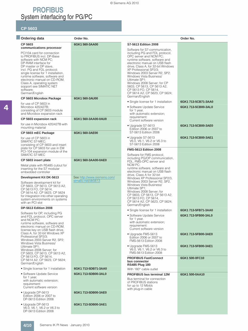
■ Ordering data Order No. Order No.
CP 5603 communications processor
6GK1 560-3AA00
PCI104 card for connection to PROFIBUS incl. DP-Base software with NCM PC; DP-RAM interface for DP master or DP slave, incl. PG and FDL protocol; single license for 1 installation, runtime software, software and electronic manual on CD-ROM, Class A, operating system sopport see SIMATIC NET software;German/English
CP 5603 Microbox Package 6GK1 560-3AU00
for use of CP 5603 in Microbox 420/427B; consisting of CP 5603 module and Microbox expansion rack
CP 5603 expansion rack 6GK1 560-3AA00-0AU0
for use in Microbox 420/427B with mounting material
CP 5603 mEC Package 6GK1 560-3AE00
for use of CP 5603 in SIMATIC S7-MEC; consisting of CP 5603 and insert plate for CP 5603 for use in EM PCI-104 expansion module of the SIMATIC S7-MEC
CP 5603 insert plate 6GK1 560-3AA00-0AE0
Metal plate with RS485 cutout for inserting for the S7 modular embedded controller
Development Kit DK-5613 See http://www.siemens.com/simatic-net/dk5613
Software development kit for CP 5603, CP 5613, CP 5613 A2, CP 5613 FO, CP 5614, CP 5614 A2, CP 5623, CP 5624 for integration into other operating system environments on systems with an PCI slot
DP-5613 Edition 2008
Software for DP, including PG and FDL protocol, OPC server and NCM PC; runtime software, software and electronic manual on CD-ROM, license key on USB flash drive, Class A, for 32-bit Windows XP Professional SP2/3; Windows 2003 Server R2, SP2; Windows Vista Business/Ultimate SP1; Windows 2008 Server; for CP 5603, CP 5613, CP 5613 A2, CP 5613 FO, CP 5614, CP 5614 A2, CP 5623, CP 5624; German/English
• Single license for 1 installation 6GK1 713-5DB71-3AA0
• Software Update Service for 1 year, with automatic extension; requirement: Current software version
6GK1 713-5DB00-3AL0
• Upgrade DP-5613 Edition 2006 or 2007 to DP-5613 Edition 2008
6GK1 713-5DB00-3AE0
• Upgrade DP-5613 V6.0, V6.1, V6.2 or V6.3 to DP-5613 Edition 2008
6GK1 713-5DB00-3AE1
S7-5613 Edition 2008
Software for S7-communication, including PG and FDL protocol, OPC server and NCM PC; runtime software, software and electronic manual on USB flash drive, Class A, for 32-bit Windows XP Professional SP2/3; Windows 2003 Server R2, SP2; Windows Vista Business/Ultimate SP1; Windows 2008 Server; for CP 5603, CP 5613, CP 5613 A2, CP 5613 FO, CP 5614, CP 5614 A2, CP 5623, CP 5624; German/English
• Single license for 1 installation 6GK1 713-5CB71-3AA0
• Software Update Servicefor 1 year, with automatic extension; requirement: Current software version
6GK1 713-5CB00-3AL0
• Upgrade S7-5613 Edition 2006 or 2007 to S7-5613 Edition 2008
6GK1 713-5CB00-3AE0
• Upgrade S7-5613 V6.0, V6.1, V6.2 or V6.3 to S7-5613 Edition 2008
6GK1 713-5CB00-3AE1
FMS-5613 Edition 2008
Software for FMS protocol, including PG/OP communication, FDL, FMS-OPC server and NCM PC; runtime software, software and electronic manual on USB flash drive, Class A for 32-bit Windows XP Professional SP2/3, Windows 2003 Server R2, SP2, Windows Vista Business/Ultimate SP1; Windows 2008 Server; for CP 5603, CP 5613, CP 5613 A2, CP 5613 FO, CP 5614, CP 5614 A2, CP 5623, CP 5624; German/English
• Single license for 1 installation 6GK1 713-5FB71-3AA0
• Software Update Service for 1 year, with automatic extension; requirement: Current software version
6GK1 713-5FB00-3AL0
• Upgrade FMS-5613 Edition 2006 or 2007 to FMS-5613 Edition 2008
6GK1 713-5FB00-3AE0
• Upgrade FMS-5613 V6.0, V6.1, V6.2 or V6.3 to FMS-5613 Edition 2008
6GK1 713-5FB00-3AE1
PROFIBUS FastConnect bus connector RS485 Plug 180
6GK1 500-0FC10
With 180° cable outlet
PROFIBUS bus terminal 12M 6GK1 500-0AA10Bus terminal for connection of PROFIBUS stationsfor up to 12 Mbit/s with plug-in cable
Kap_04_en.fm Seite 10 Freitag, 29. Januar 2010 9:52 09
© Siemens AG 2010
PROFIBUSSystem interfacing for PG/PC
CP 5623
4/11Siemens IK PI News · January 2010
4
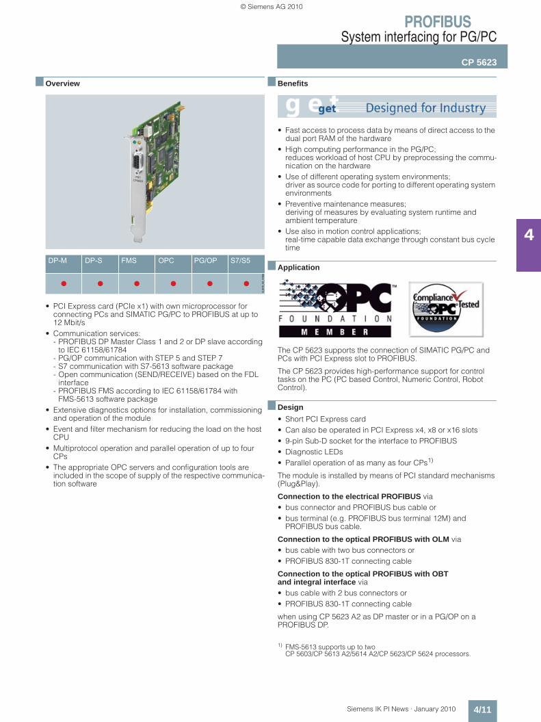
■ Overview
• PCI Express card (PCIe x1) with own microprocessor for connecting PCs and SIMATIC PG/PC to PROFIBUS at up to 12 Mbit/s
• Communication services: - PROFIBUS DP Master Class 1 and 2 or DP slave according
to IEC 61158/61784- PG/OP communication with STEP 5 and STEP 7- S7 communication with S7-5613 software package- Open communication (SEND/RECEIVE) based on the FDL
interface- PROFIBUS FMS according to IEC 61158/61784 with
FMS-5613 software package• Extensive diagnostics options for installation, commissioning
and operation of the module• Event and filter mechanism for reducing the load on the host
CPU• Multiprotocol operation and parallel operation of up to four
CPs• The appropriate OPC servers and configuration tools are
included in the scope of supply of the respective communica-tion software
■ Benefits
• Fast access to process data by means of direct access to the dual port RAM of the hardware
• High computing performance in the PG/PC; reduces workload of host CPU by preprocessing the commu-nication on the hardware
• Use of different operating system environments; driver as source code for porting to different operating system environments
• Preventive maintenance measures; deriving of measures by evaluating system runtime and ambient temperature
• Use also in motion control applications; real-time capable data exchange through constant bus cycle time
■ Application
The CP 5623 supports the connection of SIMATIC PG/PC and PCs with PCI Express slot to PROFIBUS.
The CP 5623 provides high-performance support for control tasks on the PC (PC based Control, Numeric Control, Robot Control).
■ Design
• Short PCI Express card• Can also be operated in PCI Express x4, x8 or x16 slots• 9-pin Sub-D socket for the interface to PROFIBUS• Diagnostic LEDs• Parallel operation of as many as four CPs1)
The module is installed by means of PCI standard mechanisms (Plug&Play).
Connection to the electrical PROFIBUS via• bus connector and PROFIBUS bus cable or • bus terminal (e.g. PROFIBUS bus terminal 12M) and
PROFIBUS bus cable.
Connection to the optical PROFIBUS with OLM via • bus cable with two bus connectors or • PROFIBUS 830-1T connecting cable
Connection to the optical PROFIBUS with OBT and integral interface via• bus cable with 2 bus connectors or • PROFIBUS 830-1T connecting cable
when using CP 5623 A2 as DP master or in a PG/OP on a PROFIBUS DP.
1) FMS-5613 supports up to two CP 5603/CP 5613 A2/5614 A2/CP 5623/CP 5624 processors.
Kap_04_en.fm Seite 11 Freitag, 29. Januar 2010 9:52 09
© Siemens AG 2010

PROFIBUSSystem interfacing for PG/PC
CP 5623
4/12 Siemens IK PI News · January 2010
4
■ Function
PROFIBUS DP
Access to process data with DP-Base
The CP 5623 is operated as PROFIBUS DP master module that keeps the process image (input/output and diagnostics data) in the dual port RAM (memory area on the CP). The hardware of the CP 5623 independently executes the high-performance ex-change of data with the PROFIBUS slaves. The user accesses the dual-port RAM directly.
The process data of the slaves is always consistent, i.e. the user receives the data of a slave from one and the same DP cycle.
Parallel operation of the DP-5613 and DP-Base software is not possible.
Example configuration of PROFIBUS DP for SIMATIC S5/S7 and PG/PC
Event filter mechanism
The user receives up-to-date data over two access mecha-nisms:• Cyclic polling of the DP slaves (higher loading for host CPU)• Notification by means of event/filter mode when changing the
input data of a slave (minimal loading for host CPU)
Both alternatives can be combined. This allows users to optimize use of the PC for their applications.
The event/filter mechanism can be used additionally for• Notification by means of an interrupt of the diagnostic
messages from slaves• During operation with constant bus cycle time, signaling by
means of interrupt: - Start DP cycle- End of cyclic data exchange with DP slaves
FastLogic
FastLogic means that the CP 5623 can react autonomously to as many as four plant statuses. This results in a short response time and independence from the host application, e.g. fast shutdown of devices.
DP programming interface
The DP programming interface (DP-Base) of the CP 5623 has the following functionality:• DP Master Class 1 including acyclic DP expansions• DP Master Class 2 including acyclic DP expansions • DP slave
The process data is accessed directly through the dual-port RAM. The DP RAM interface not only offers fast access as DP master/slave but also a basis for porting to other operating system environments (e.g. VXWorks, QNX, RMOS, RTX).
Administrative function calls (initialization and management services, as well as diagnostic functions) are provided through a library (DP_BASE.DLL or DPS_BASE.DLL).
Development Kit DK-5613
The Development Kit DK-5613 provides access to the functions DP Master Class 1 including acyclic DP expansions
The software development kit DK-5613 enables the communi-cations processor CP 5623 to be integrated into any operating system environments. The kit contains the necessary source code, including the descriptions in PDF format, and can be downloaded free of charge from the Internet.
S7-400 withCP 443-5 Extended(DP master)
S7-300 with CP 342-5(DP master)
PC with CP 5613 A2/ CP 5623and DP Base(DP master)
PG with STEP 7/ STEP 5 and CP 5711
Third-party device
S5 withIM 308-C
G_I
K10
_XX
_500
07
ET 200S
ET 200pro
PROFIBUS DP
Kap_04_en.fm Seite 12 Freitag, 29. Januar 2010 9:52 09
© Siemens AG 2010
PROFIBUSSystem interfacing for PG/PC
CP 5623
4/13Siemens IK PI News · January 2010
4
■ Function (continued)
Access to process data with DP-5613 • DP Master Class 1
The CP 5623 operates as a DP Master Class 1 according to IEC 61158/61784 and processes data communication with the distributed stations (DP slaves) completely autonomously. The central controller exchanges information with the DP slaves (e.g. ET 200S) in a specified, constantly repeating message cycle. The DP programming interface (DPLib.DLL) provides the PC programmer with function calls for data transfer. The DP interface also provides the SYNC and FREEZE functions as well as activation and deactivation of slaves.
The DP function expansions for Master Class 1 make it possible to perform acyclic read and write functions (DS_READ, DS_WRITE) as well as acknowledgement of alarms (ALARM_ACK) at the same time as processing cyclic data communication. Data that are to be transferred in non-isochronous mode (e.g. parameter-ization data) are only rarely changed, in comparison to the cyclic measured values, and are transferred at lower priority in parallel with the cyclic high-speed useful data transfer. Alarm acknowl-edgement by the master ensures reliable transfer of the alarms from DP slaves.
Parallel operation of the DP-Base and DP-5613 software is not possible.• DP Master Class 2
Apart from the DP Master Class 1 services, the CP 5623 also offers DP Master Class 2 services to IEC 61158/61784 in con-junction with the DP programming interface. Devices of this type (programming, configuration or operating devices) are used during start-up, for configuring the DP system or for operating the system during normal operation (diagnostics). The DP programming interface provides the following services:• Master diagnostics• Slave diagnostics• Reading the inputs/outputs of a slave• Reading configuration data• Changing slave addresses
The extended DP functions comprise acyclic access to the parameters and measured values of a slave (e.g. field devices of process automation and intelligent HMI devices). This type of slave must be supplied with extensive parameter data during start-up and during normal operation (DS_READ, DS_WRITE).
Software for PG/OP communication
This software supports programming of the SIMATIC S5/S7 con-trollers (with the exception of SIMATIC S5-95U) over PROFIBUS in combination with STEP 5/STEP 7. The PG/OP communication for the CP 5623 is already available following installation of the CP 5623 (DP-Base). No additional software packages are re-quired.
Open communication(SEND/RECEIVE on the basis of the FDL interface)
SEND/RECEIVE (FDL interface) is already available following installation of the CP 5623 (DP-Base) and provides services for data transfer, diagnostics and management. No additional software packages are required.
Software for S7 communication (S7-5613)
SIMATIC S7 system components communicate with each other using S7 communication functions. The S7 programming inter-face provides programming device/PC user programs with access to SIMATIC S7 system components. This makes for easy and flexible access to SIMATIC S7 data.
The following services are available with S7 communication:
Administrative services • Connection management• Mini-database• Trace
Data transfer services • Read/write variables• BSEND/BRECEIVE (up to 64 KB per task)
Software for PROFIBUS FMS (FMS-5613)
With the FMS programming interface, PG/PCs can exchange different manufacturer data with FMS-capable controllers (e.g. S5 and S7) and field devices. Open communication is assured by using the FMS interface.
The FMS interface offers the following services:• Administrative services• CRL management services• FMS connection management services• Object directory management services for clients and server• Variable services for clients and servers
(Read, Write, Information Report)• Server functionality • VFD services (Virtual Field Device) for clients and servers• Bus access information services (live list)• Trace and mini-database
User interfaces • OPC interface
The OPC server included in the respective software package can be used as the standard programming interface for the PROFIBUS DP, open communication, S7 communication and PROFIBUS FMS in order to connect automation technology applications to OPC-compatible Windows applications (Office, HMI systems, etc.)• Programming interface via C-library
The programming interfaces for existing applications are implemented as Dynamic Link Libraries (DLL). The released compilers can be found in the readme file of the SIMATIC NET CD products at http://www.siemens.com/automation/csi/net.
For Borland programming interfaces (e.g. DELPHI), partner solutions from the company SoftwareOption are offered.
For solutions for other operating systems, see Development Kit DK-5613.
Configuration • The S7 communication protocol, open communication
protocol, DP protocol (DP-V0/DP-V1/DP-V2), and FMS proto-col are configured in STEP 7 or NCM PC V5.1 +SP2.
• The NCM PC configuration tool is included in the scope of delivery of the PROFIBUS software packages.
Diagnostics
Comprehensive diagnostic tools are available (for installation, start-up and operation) for the module itself and for the PROFIBUS DP network. These tools can be used for quick and easy start-up of a PROFIBUS network with a CP 5623.
Kap_04_en.fm Seite 13 Freitag, 29. Januar 2010 9:52 09
© Siemens AG 2010
PROFIBUSSystem interfacing for PG/PC
CP 5623
4/14 Siemens IK PI News · January 2010
4
■ Technical specifications
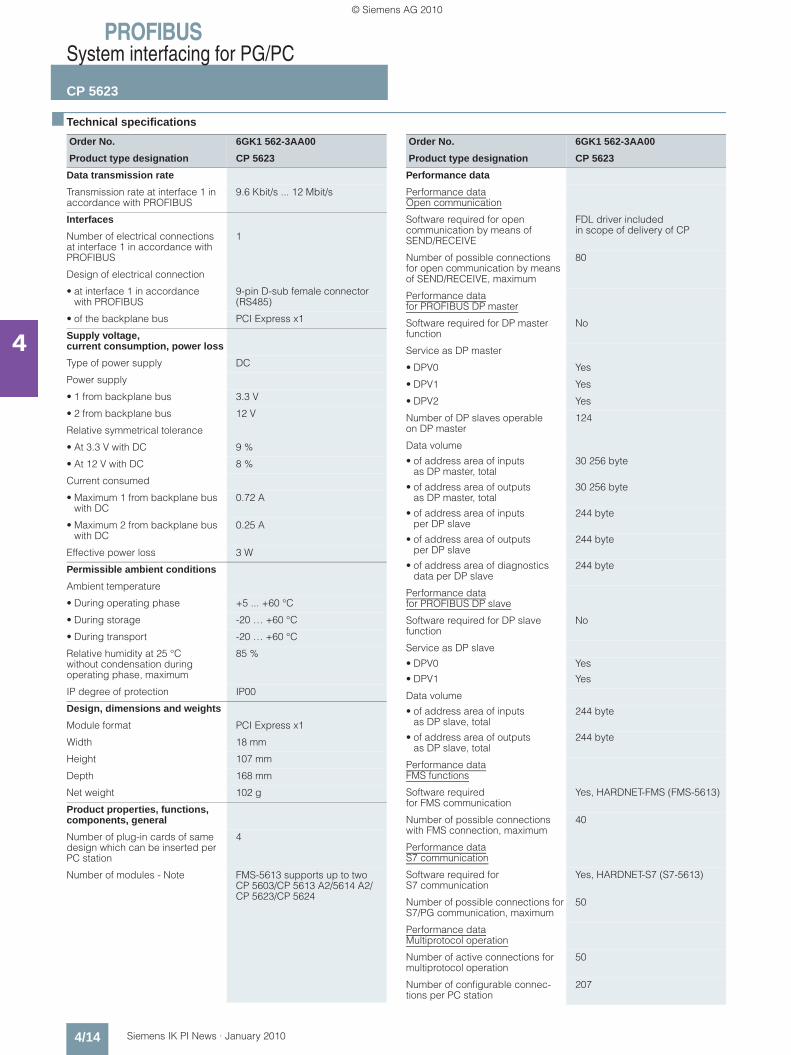
Order No. 6GK1 562-3AA00
Product type designation CP 5623
Data transmission rate
Transmission rate at interface 1 in accordance with PROFIBUS
9.6 Kbit/s ... 12 Mbit/s
Interfaces
Number of electrical connections at interface 1 in accordance with PROFIBUS
1
Design of electrical connection
• at interface 1 in accordance with PROFIBUS
9-pin D-sub female connector (RS485)
• of the backplane bus PCI Express x1
Supply voltage, current consumption, power loss
Type of power supply DC
Power supply
• 1 from backplane bus 3.3 V
• 2 from backplane bus 12 V
Relative symmetrical tolerance
• At 3.3 V with DC 9 %
• At 12 V with DC 8 %
Current consumed
• Maximum 1 from backplane bus with DC
0.72 A
• Maximum 2 from backplane bus with DC
0.25 A
Effective power loss 3 W
Permissible ambient conditions
Ambient temperature
• During operating phase +5 ... +60 °C
• During storage -20 … +60 °C
• During transport -20 … +60 °C
Relative humidity at 25 °C without condensation during operating phase, maximum
85 %
IP degree of protection IP00
Design, dimensions and weights
Module format PCI Express x1
Width 18 mm
Height 107 mm
Depth 168 mm
Net weight 102 g
Product properties, functions, components, general
Number of plug-in cards of same design which can be inserted per PC station
4
Number of modules - Note FMS-5613 supports up to twoCP 5603/CP 5613 A2/5614 A2/CP 5623/CP 5624
Order No. 6GK1 562-3AA00
Product type designation CP 5623
Performance data
Performance dataOpen communication
Software required for open communication by means of SEND/RECEIVE
FDL driver includedin scope of delivery of CP
Number of possible connections for open communication by means of SEND/RECEIVE, maximum
80
Performance datafor PROFIBUS DP master
Software required for DP master function
No
Service as DP master
• DPV0 Yes
• DPV1 Yes
• DPV2 Yes
Number of DP slaves operable on DP master
124
Data volume
• of address area of inputs as DP master, total
30 256 byte
• of address area of outputs as DP master, total
30 256 byte
• of address area of inputs per DP slave
244 byte
• of address area of outputs per DP slave
244 byte
• of address area of diagnostics data per DP slave
244 byte
Performance datafor PROFIBUS DP slave
Software required for DP slave function
No
Service as DP slave
• DPV0 Yes
• DPV1 Yes
Data volume
• of address area of inputs as DP slave, total
244 byte
• of address area of outputs as DP slave, total
244 byte
Performance dataFMS functions
Software required for FMS communication
Yes, HARDNET-FMS (FMS-5613)
Number of possible connections with FMS connection, maximum
40
Performance dataS7 communication
Software required for S7 communication
Yes, HARDNET-S7 (S7-5613)
Number of possible connections for S7/PG communication, maximum
50
Performance dataMultiprotocol operation
Number of active connections for multiprotocol operation
50
Number of configurable connec-tions per PC station
207
Kap_04_en.fm Seite 14 Freitag, 29. Januar 2010 9:52 09
© Siemens AG 2010
PROFIBUSSystem interfacing for PG/PC
CP 5623
4/15Siemens IK PI News · January 2010
4
■ Technical specifications (continued)
■ Ordering data Order No. Order No.
Order No. 6GK1 562-3AA00
Product type designation CP 5623
Product functions Management, configuration, programming
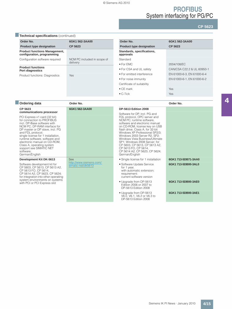
Configuration software required NCM PC included in scope of delivery
Product functions Port diagnostics
Product functions: Diagnostics Yes
Order No. 6GK1 562-3AA00
Product type designation CP 5623
Standards, specifications, approvals
Standard
• For EMC 2004/108/EC
• For CSA and UL safety CAN/CSA C22.2 & UL 60950-1
• For emitted interference EN 61000-6-3, EN 61000-6-4
• For noise immunity EN 61000-6-1, EN 61000-6-2
Certificate of suitability
• CE mark Yes
• C-Tick Yes
CP 5623 communications processor
6GK1 562-3AA00
PCI Express x1 card (32 bit) for connection to PROFIBUS incl. DP-Base software with NCM PC; DP-RAM interface for DP master or DP slave, incl. PG and FDL protocol; single license for 1 installation, runtime software, software and electronic manual on CD-ROM, Class A, operating system sopport see SIMATIC NET software;German/English
Development Kit DK-5613 See http://www.siemens.com/ simatic-net/dk5613Software development kit for
CP 5603, CP 5613, CP 5613 A2, CP 5613 FO, CP 5614, CP 5614 A2, CP 5623, CP 5624; for integration into other operating system environments on systems with PCI or PCI Express slot
DP-5613 Edition 2008
Software for DP, incl. PG and FDL protocol, OPC server and NCM PC; runtime software, software and electronic manual on CD-ROM, license key on USB flash drive, Class A, for 32-bit Windows XP Professional SP2/3; Windows 2003 Server R2, SP2; Windows Vista Business/Ultimate SP1; Windows 2008 Server; for CP 5603, CP 5613, CP 5613 A2, CP 5613 FO, CP 5614, CP 5614 A2, CP 5623, CP 5624;German/English
• Single license for 1 installation 6GK1 713-5DB71-3AA0
• Software Update Service for 1 year, with automatic extension; requirement: current software version
6GK1 713-5DB00-3AL0
• Upgrade from DP-5613 Edition 2006 or 2007 to DP-5613 Edition 2008
6GK1 713-5DB00-3AE0
• Upgrade from DP-5613 V6.0, V6.1, V6.2 or V6.3 to DP-5613 Edition 2008
6GK1 713-5DB00-3AE1
Kap_04_en.fm Seite 15 Freitag, 29. Januar 2010 9:52 09
© Siemens AG 2010
PROFIBUSSystem interfacing for PG/PC
CP 5623
4/16 Siemens IK PI News · January 2010
4
■ Ordering data Order No. ■ More information
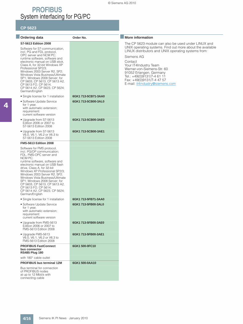
The CP 5623 module can also be used under LINUX and UNIX operating systems. Find out more about the available LINUX distributors and UNIX operating systems from:
Siemens AGContact Your IT4Industry Team Werner-von-Siemens-Str. 60 91052 Erlangen, Germany Tel.: +49(0)9131/7-4 61 11Fax: +49(0)9131/7-4 47 57E-mail: [email protected]
S7-5613 Edition 2008
Software for S7-communication, incl. PG and FDL protocol, OPC server and NCM PC; runtime software, software and electronic manual on USB stick, Class A, for 32-bit Windows XP Professional SP2/3; Windows 2003 Server R2, SP2; Windows Vista Business/Ultimate SP1; Windows 2008 Server; for CP 5603, CP 5613, CP 5613 A2, CP 5613 FO, CP 5614, CP 5614 A2, CP 5623, CP 5624;German/English
• Single license for 1 installation 6GK1 713-5CB71-3AA0
• Software Update Servicefor 1 year, with automatic extension; requirement: current software version
6GK1 713-5CB00-3AL0
• Upgrade from S7-5613Edition 2006 or 2007 toS7-5613 Edition 2008
6GK1 713-5CB00-3AE0
• Upgrade from S7-5613V6.0, V6.1, V6.2 or V6.3 to S7-5613 Edition 2008
6GK1 713-5CB00-3AE1
FMS-5613 Edition 2008
Software for FMS protocol, incl. PG/OP communication; FDL, FMS-OPC server and NCM PC; runtime software, software and electronic manual on USB flash drive, Class A, for 32-bit Windows XP Professional SP2/3; Windows 2003 Server R2, SP2; Windows Vista Business/Ultimate SP1; Windows 2008 Server; for CP 5603, CP 5613, CP 5613 A2, CP 5613 FO, CP 5614, CP 5614 A2, CP 5623, CP 5624;German/English
• Single license for 1 installation 6GK1 713-5FB71-3AA0
• Software Update Servicefor 1 year, with automatic extension; requirement: current software version
6GK1 713-5FB00-3AL0
• Upgrade from FMS-5613 Edition 2006 or 2007 to FMS-5613 Edition 2008
6GK1 713-5FB00-3AE0
• Upgrade FMS-5613V6.0, V6.1, V6.2 or V6.3 toFMS-5613 Edition 2008
6GK1 713-5FB00-3AE1
PROFIBUS FastConnect bus connector RS485 Plug 180
6GK1 500-0FC10
with 180° cable outlet
PROFIBUS bus terminal 12M 6GK1 500-0AA10
Bus terminal for connection of PROFIBUS nodes at up to 12 Mbit/s with connecting cable
Kap_04_en.fm Seite 16 Freitag, 29. Januar 2010 9:52 09
© Siemens AG 2010
PROFIBUSSystem interfacing for PG/PC
CP 5624
4/17Siemens IK PI News · January 2010
4
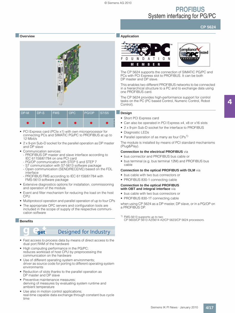
■ Overview
• PCI Express card (PCIe x1) with own microprocessor for connecting PCs and SIMATIC PG/PC to PROFIBUS at up to 12 Mbit/s
• 2 x 9-pin Sub-D socket for the parallel operation as DP master and DP slave
• Communication services: - PROFIBUS DP master and slave interface according to
IEC 61158/61784 on one PCI card- PG/OP communication with STEP 5 and STEP 7- S7 communication with S7-5613 software package- Open communication (SEND/RECEIVE) based on the FDL
interface- PROFIBUS FMS according to IEC 61158/61784 with
FMS-5613 software package• Extensive diagnostics options for installation, commissioning
and operation of the module• Event and filter mechanism for reducing the load on the host
CPU• Multiprotocol operation and parallel operation of up to four CPs• The appropriate OPC servers and configuration tools are
included in the scope of supply of the respective communi-cation software
■ Benefits
• Fast access to process data by means of direct access to the dual port RAM of the hardware
• High computing performance in the PG/PC; reduces workload of host CPU by preprocessing the communication on the hardware
• Use of different operating system environments; driver as source code for porting to different operating system environments
• Reduction of slots thanks to the parallel operation as DP master and DP slave
• Preventive maintenance measures; deriving of measures by evaluating system runtime and ambient temperature
• Use also in motion control applications; real-time capable data exchange through constant bus cycle time
■ Application
The CP 5624 supports the connection of SIMATIC PG/PC and PCs with PCI Express slot to PROFIBUS. It can be both DP master and DP slave.
This enables two different PROFIBUS networks to be connected in a hierarchical structure to a PC and to exchange data using one PROFIBUS card.
The CP 5624 provides high-performance support for control tasks on the PC (PC based Control, Numeric Control, Robot Control).
■ Design
• Short PCI Express card• Can also be operated in PCI Express x4, x8 or x16 slots• 2 x 9-pin Sub-D socket for the interface to PROFIBUS• Diagnostic LEDs• Parallel operation of as many as four CPs1)
The module is installed by means of PCI standard mechanisms (Plug&Play).
Connection to the electrical PROFIBUS via• bus connector and PROFIBUS bus cable or • bus terminal (e.g. bus terminal 12M) and PROFIBUS bus
cable
Connection to the optical PROFIBUS with OLM via• bus cable with two bus connectors or • PROFIBUS 830-1 connecting cable
Connection to the optical PROFIBUS with OBT and integral interface via• bus cable with two bus connectors or • PROFIBUS 830-1T connecting cable
when using CP 5624 as a DP master, DP slave, or in a PG/OP on a PROFIBUS DP.
1) FMS-5613 supports up to two CP 5603/CP 5613 A2/5614 A2/CP 5623/CP 5624 processors.
Kap_04_en.fm Seite 17 Freitag, 29. Januar 2010 9:52 09
© Siemens AG 2010
PROFIBUSSystem interfacing for PG/PC
CP 5624
4/18 Siemens IK PI News · January 2010
4
■ Function
PROFIBUS DP
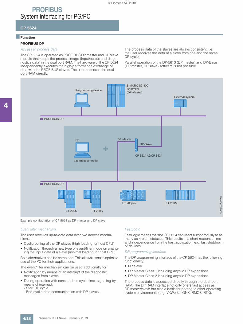
Access to process data
The CP 5624 is operated as PROFIBUS DP master and DP slave module that keeps the process image (input/output and diag-nostics data) in the dual port RAM. The hardware of the CP 5624 independently executes the high-performance exchange of data with the PROFIBUS slaves. The user accesses the dual-port RAM directly.
The process data of the slaves are always consistent, i.e. the user receives the data of a slave from one and the same DP cycle.
Parallel operation of the DP-5613 (DP master) and DP-Base (DP master, DP slave) software is not possible.
Example configuration of CP 5624 as DP master and DP slave
Event filter mechanism
The user receives up-to-date data over two access mecha-nisms:• Cyclic polling of the DP slaves (high loading for host CPU)• Notification through a new type of event/filter mode on chang-
ing the input data of a slave (minimal loading for host CPU)
Both alternatives can be combined. This allows users to optimize use of the PC for their applications.
The event/filter mechanism can be used additionally for• Notification by means of an interrupt of the diagnostic
messages from slaves• During operation with constant bus cycle time, signaling by
means of interrupt: - Start DP cycle- End cyclic data communication with DP slaves
FastLogic
FastLogic means that the CP 5624 can react autonomously to as many as 4 plant statuses. This results in a short response time and independence from the host application, e.g. fast shutdown of devices.
DP programming interface
The DP programming interface of the CP 5624 has the following functionality:• DP slave• DP Master Class 1 including acyclic DP expansions• DP Master Class 2 including acyclic DP expansions
The process data is accessed directly through the dual-port RAM. The DP RAM interface not only offers fast access as DP master/slave but also a basis for porting to other operating system environments (e.g. VXWorks, QNX, RMOS, RTX).
External system
SIMATIC S7-400Controller(DP-Master)
Programming device
e.g. robot controller
DP-Master
DP-Slave
G_I
K10
_XX
_500
21
PROFIBUS DP
PROFIBUS DP
PC
CP 5614 A2/CP 5624
ET 200SET 200S
ET 200MET 200pro
Kap_04_en.fm Seite 18 Freitag, 29. Januar 2010 9:52 09
© Siemens AG 2010
PROFIBUSSystem interfacing for PG/PC
CP 5624
4/19Siemens IK PI News · January 2010
4
■ Function (continued)
Administrative function calls (initialization and management services as well as diagnostic functions) are provided through a DP master and DP slave library (DP_BASE.DLL and DPS_BASE.DLL).
A transfer mechanism (PC application) can be activated in the software as a linking component for data transfer between the master and slave interface.
Defined I/O data can be transferred in this manner between the master interface and the slave interface.
The two connected PROFIBUS networks can be operated with different PROFIBUS bus parameters because they are indepen-dent of each other.
Development Kit DK-5613
The Development Kit DK-5613 provides access to the functions DP Master Class 1 and DP slave (incl. acyclic DP expansions)
The software development kit DK-5613 enables the CP 5624 communications processor to be integrated into any operating system environments. The kit contains the necessary source code, including the descriptions in PDF format, and can be downloaded free of charge via the Internet.
Access to process data with DP-5613 • DP Master Class 1
The CP 5624 operates as a DP Master Class 1 according to IEC 61158/61784 and processes data communication with the distributed stations (DP slaves) completely autonomously. The central controller exchanges information with the DP slaves (e.g. ET 200S) in a specified, constantly repeating message cycle. The DP programming interface (DPLib.DLL) provides the PC programmer with function calls for data transfer. The DP interface also provides the SYNC and FREEZE functions as well as activation and deactivation of slaves.
The DP function expansions for Master Class 1 make it possible to perform acyclic read and write functions (DS_READ, DS_WRITE) as well as acknowledgement of alarms (ALARM_ACK) at the same time as processing cyclic data communication. Data to be transferred in acyclic mode (e.g. parameterization data) is only rarely changed, in comparison to the cyclic measured values, and is transferred at lower priority in parallel with the cyclic high-speed useful data transfer. Alarm acknowledgement by the master ensures reliable transfer of the alarms from DP slaves (DS_READ, DS_WRITE).
Parallel operation of the DP-Base and DP-5613 software is not possible.• DP Master Class 2
Apart from the DP Master Class 1 services, the CP 5624 also offers DP Master Class 2 services to IEC 61158/61784 in con-junction with the DP programming interface. Devices of this type (programming, configuration or operating devices) are used during start-up, for configuring the DP system or for operating the system during normal operation (diagnostics). The DP programming interface provides the following services:• Master diagnostics• Slave diagnostics• Reading the inputs/outputs of a slave• Reading configuration data • Changing slave addresses
The extended DP functions comprise acyclic access to the parameters and measured values of a slave (e.g. field devices of process automation and intelligent HMI devices). This type of slave must be supplied with extensive parameter data during start-up and during normal operation. (DS_READ, DS_WRITE).
Software for PG/OP communication
This software supports programming of the SIMATIC S5/S7 con-trollers (with the exception of SIMATIC S5-95U) over PROFIBUS in combination with STEP 5/STEP 7. The PG/OP communication for the CP 5624 is already available following installation of the CP 5624 (DP-Base). No additional software packages are re-quired.
Open communication (SEND/RECEIVE on the basis of the FDL interface)
SEND/RECEIVE (FDL interface) is already available following installation of the CP 5624 (DP-Base) and provides services for data transfer, diagnostics and management. No additional software packages are required.
Software for S7 communication (S7-5613)
SIMATIC S7 system components communicate with each other using S7 communication functions. The S7 programming inter-face provides programming device/PC user programs with access to SIMATIC S7 system components. This makes for easy and flexible access to SIMATIC S7 data.
The following services are available with S7 communication:
Administrative services • Connection management• Mini-database• Trace
Data transfer services • Read/write variables• BSEND/BRECEIVE (up to 64 KB per task)
Software for PROFIBUS FMS (FMS-5613)
With the FMS programming interface, PG/PCs can exchange different manufacturer data with FMS-capable controllers (e.g. S5 and S7) and field devices. Open communication is assured by using the FMS interface.
The FMS interface offers the following services:• Administrative services• CRL management services• FMS connection management services• Object directory management services for clients and server• Variable services for clients and servers
(Read, Write, Information Report)• Server functionality• VFD services (Virtual Field Device) for clients and servers• Bus access information services (live list)• Trace and mini-database
Kap_04_en.fm Seite 19 Freitag, 29. Januar 2010 9:52 09
© Siemens AG 2010

PROFIBUSSystem interfacing for PG/PC
CP 5624
4/20 Siemens IK PI News · January 2010
4
■ Function (continued)
User interfaces • OPC interface
The OPC server included in the respective software package can be used as the standard programming interface for the PROFIBUS DP (DP master and DP slave), open communication, S7 communication and PROFIBUS FMS in order to connect automation technology applications to OPC-compatible Windows applications (Office, HMI systems, etc.).• Programming interface via C-library
The programming interfaces for existing applications are implemented as Dynamic Link Libraries (DLL). The released compilers can be found in the readme file of the SIMATIC NET CD products at http://www.siemens.com/automation/csi/net.
For Borland programming interfaces (e.g. DELPHI), partner solutions from the company SoftwareOption are offered.
For solutions for other operating systems, see Development Kit DK-5613.
Configuration • The S7 communication protocol, open communication proto-
col, DP protocol (DP-V0/DP-V1/DP-V2) and FMS protocol are configured in STEP 7 or NCM PC version V5.1 +SP2 or higher.
• The NCM PC configuration tool is included in the scope of delivery of the PROFIBUS software packages.
Diagnostics
Comprehensive diagnostic tools are available (for installation, start-up and operation) for the module itself and for the PROFIBUS DP network. These tools can be used for quick and easy start-up of a PROFIBUS DP network with a CP 5624.
Configuration example for CP 5624
■ Technical specifications
Transfermechanism
Distributed I/Os
SIMATIC S7-300 withCP 342-5 (DP-Master)
G_I
K10
_XX
_501
10
ET 200S
PROFIBUS
PROFIBUS
ET 200M
RS 485
DP-Master
DP-Slave
CP 5614 A2/ CP 5624
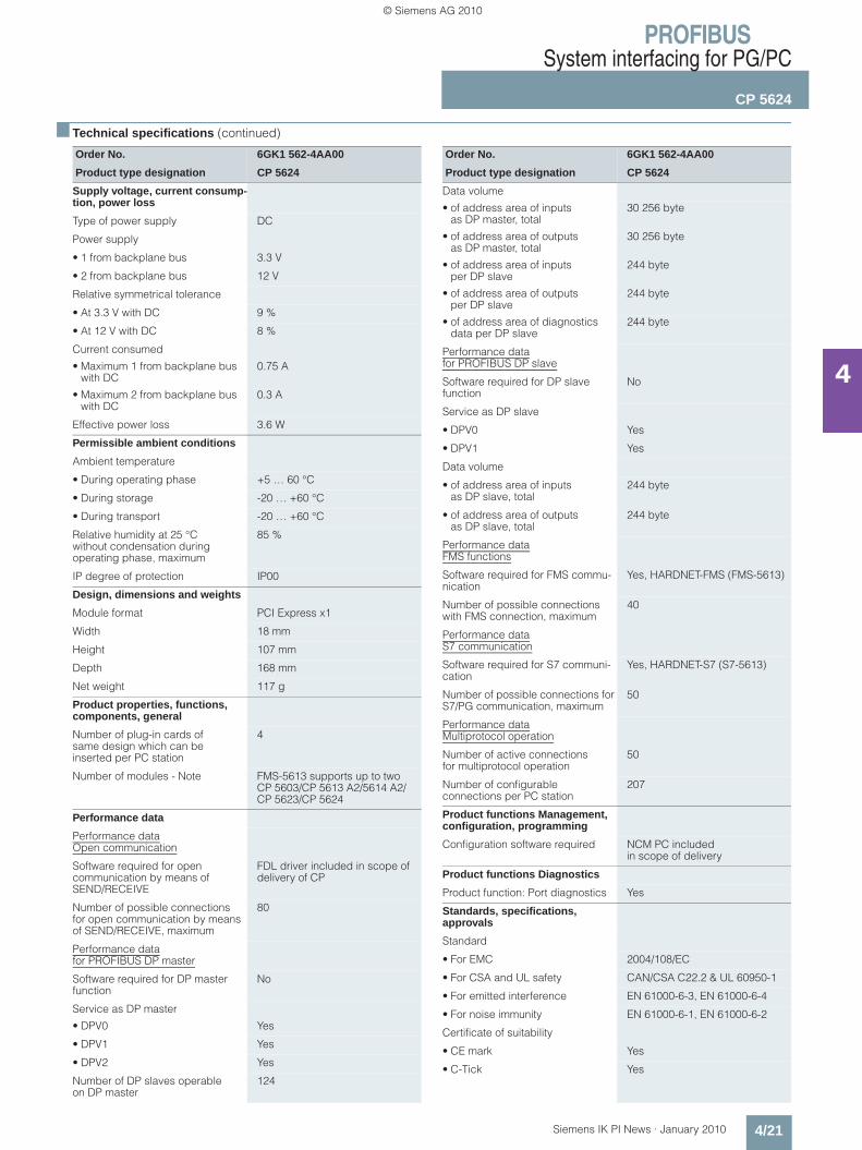
Order No. 6GK1 562-4AA00
Product type designation CP 5624
Data transmission rate
Data transmission rate
• at interface 1 in accordance with PROFIBUS
9.6 Kbit/s ... 12 Mbit/s
• at interface 2 in accordance with PROFIBUS
9.6 Kbit/s ... 12 Mbit/s
Order No. 6GK1 562-4AA00
Product type designation CP 5624
Interfaces
Number of electrical connections
• at interface 1 in accordance with PROFIBUS
1
• at interface 2 in accordance with PROFIBUS
1
Design of electrical connection
• at interface 1 in accordance with PROFIBUS
9-pin D-sub female connector (RS485)
• at interface 2 in accordance with PROFIBUS
9-pin D-sub female connector(RS485)
• of the backplane bus PCI Express x1
Kap_04_en.fm Seite 20 Freitag, 29. Januar 2010 9:52 09
© Siemens AG 2010
PROFIBUSSystem interfacing for PG/PC
CP 5624
4/21Siemens IK PI News · January 2010
4
■ Technical specifications (continued)
Order No. 6GK1 562-4AA00
Product type designation CP 5624
Supply voltage, current consump-tion, power loss
Type of power supply DC
Power supply
• 1 from backplane bus 3.3 V
• 2 from backplane bus 12 V
Relative symmetrical tolerance
• At 3.3 V with DC 9 %
• At 12 V with DC 8 %
Current consumed
• Maximum 1 from backplane bus with DC
0.75 A
• Maximum 2 from backplane bus with DC
0.3 A
Effective power loss 3.6 W
Permissible ambient conditions
Ambient temperature
• During operating phase +5 … 60 °C
• During storage -20 … +60 °C
• During transport -20 … +60 °C
Relative humidity at 25 °C without condensation during operating phase, maximum
85 %
IP degree of protection IP00
Design, dimensions and weights
Module format PCI Express x1
Width 18 mm
Height 107 mm
Depth 168 mm
Net weight 117 g
Product properties, functions, components, general
Number of plug-in cards of same design which can beinserted per PC station
4
Number of modules - Note FMS-5613 supports up to two CP 5603/CP 5613 A2/5614 A2/CP 5623/CP 5624
Performance data
Performance dataOpen communication
Software required for open communication by means of SEND/RECEIVE
FDL driver included in scope of delivery of CP
Number of possible connectionsfor open communication by means of SEND/RECEIVE, maximum
80
Performance datafor PROFIBUS DP master
Software required for DP master function
No
Service as DP master
• DPV0 Yes
• DPV1 Yes
• DPV2 Yes
Number of DP slaves operable on DP master
124
Order No. 6GK1 562-4AA00
Product type designation CP 5624
Data volume
• of address area of inputs as DP master, total
30 256 byte
• of address area of outputs as DP master, total
30 256 byte
• of address area of inputs per DP slave
244 byte
• of address area of outputs per DP slave
244 byte
• of address area of diagnostics data per DP slave
244 byte
Performance datafor PROFIBUS DP slave
Software required for DP slave function
No
Service as DP slave
• DPV0 Yes
• DPV1 Yes
Data volume
• of address area of inputs as DP slave, total
244 byte
• of address area of outputs as DP slave, total
244 byte
Performance dataFMS functions
Software required for FMS commu-nication
Yes, HARDNET-FMS (FMS-5613)
Number of possible connections with FMS connection, maximum
40
Performance dataS7 communication
Software required for S7 communi-cation
Yes, HARDNET-S7 (S7-5613)
Number of possible connections for S7/PG communication, maximum
50
Performance dataMultiprotocol operation
Number of active connections for multiprotocol operation
50
Number of configurable connections per PC station
207
Product functions Management, configuration, programming
Configuration software required NCM PC includedin scope of delivery
Product functions Diagnostics
Product function: Port diagnostics Yes
Standards, specifications, approvals
Standard
• For EMC 2004/108/EC
• For CSA and UL safety CAN/CSA C22.2 & UL 60950-1
• For emitted interference EN 61000-6-3, EN 61000-6-4
• For noise immunity EN 61000-6-1, EN 61000-6-2
Certificate of suitability
• CE mark Yes
• C-Tick Yes
Kap_04_en.fm Seite 21 Freitag, 29. Januar 2010 9:52 09
© Siemens AG 2010

PROFIBUSSystem interfacing for PG/PC
CP 5624
4/22 Siemens IK PI News · January 2010
4
■ Ordering data Order No. Order No.
CP 5614 A2 communications processor
6GK1 562-4AA00
PCI Express x1 card (32 bit) master and slave connection to PROFIBUS incl. DP-base software with NCM PC; DP-RAM interface for DP master, incl. PG and FDL protocol; single license for 1 installation, runtime software, software and electronic manual on CD-ROM, Class A, operating system sopport see SIMATIC NET software; German/English
Development Kit DK-5613 See http://www.siemens.com/simatic-net/dk5613
Software development kit for CP 5603, CP 5613, CP 5613 A2, CP 5613 FO, CP 5614, CP 5614 A2, CP 5623, CP 5624; for integration into other operating system environments on systems with PCI or PCI Express slot
DP-5613, 2008 Edition
Software for DP,incl. PG and FDL protocol, OPC server and NCM PC; runtime software, software and electronic manual on CD-ROM, license key on USB flash drive, Class A, for 32-bit Windows XP Professional SP2/3; Windows 2003 Server R2, SP2; Windows Vista Business/Ultimate SP1; Windows 2008 Server; for CP 5603, CP 5613, CP 5613 A2, CP 5613 FO, CP 5614, CP 5614 A2, CP 5623, CP 5624; German/English
• Single license for 1 installation 6GK1 713-5DB71-3AA0
• Software Update Service for 1 year, with automatic extension; requirement: current software version
6GK1 713-5DB00-3AL0
• Upgrade from DP-5613 Edition 2006 or 2007 to DP-5613 Edition 2008
6GK1 713-5DB00-3AE0
• Upgrade from DP-5613 V6.0, V6.1, V6.2 or V6.3 to DP-5613 Edition 2008
6GK1 713-5DB00-3AE1
S7-5613 Edition 2008
Software for S7-communication, incl. PG and FDL protocol, OPC server and NCM PC; runtime software, software and electronic manual on USB flash drive, Class A, for 32-bit Windows XP Professional SP2/3; Windows 2003 Server R2, SP2; Windows Vista Business/Ultimate SP1; Windows 2008 Server; for CP 5603, CP 5613, CP 5613 A2, CP 5613 FO, CP 5614, CP 5614 A2, CP 5623, CP 5624; German/English
• Single license for 1 installation 6GK1 713-5CB71-3AA0
• Software Update Service for 1 year, with automatic extension; requirement: current software version
6GK1 713-5CB00-3AL0
• Upgrade from S7-5613 Edition 2006 or 2007 to S7-5613 Edition 2008
6GK1 713-5CB00-3AE0
• Upgrade from S7-5613 V6.0, V6.1, V6.2 or V6.3 to S7-5613 Edition 2008
6GK1 713-5CB00-3AE1
FMS-5613 Edition 2008
Software for FMS protocol, incl. PG/OP communication; FDL, FMS-OPC server and NCM PC; runtime software, software and electronic manual on USB flash drive, Class A, for 32-bit Windows XP Professional SP2/3; Windows 2003 Server R2, SP2; Windows Vista Business/Ultimate SP1; Windows 2008 Server; for CP 5603, CP 5613, CP 5613 A2, CP 5613 FO, CP 5614, CP 5614 A2, CP 5623, CP 5624;German/English
• Single license for 1 installation 6GK1 713-5FB71-3AA0
• Software Update Service for 1 year, with automatic extension; requirement: current software version
6GK1 713-5FB00-3AL0
• Upgrade from FMS-5613 Edition 2006 or 2007 to FMS-5613 Edition 2008
6GK1 713-5FB00-3AE0
• Upgrade FMS-5613 V6.0, V6.1, V6.2 or V6.3 to FMS-5613 Edition 2008
6GK1 713-5FB00-3AE1
PROFIBUS FastConnect bus connector RS485 Plug 180
6GK1 500-0FC10
with 180° cable outlet
PROFIBUS bus terminal 12M 6GK1 500-0AA10
Bus terminal for connection of PROFIBUS nodes at up to 12 Mbit/s with connecting cable
Kap_04_en.fm Seite 22 Freitag, 29. Januar 2010 9:52 09
© Siemens AG 2010
PROFIBUSSystem interfacing for PG/PC
CP 5711
4/23Siemens IK PI News · January 2010
4
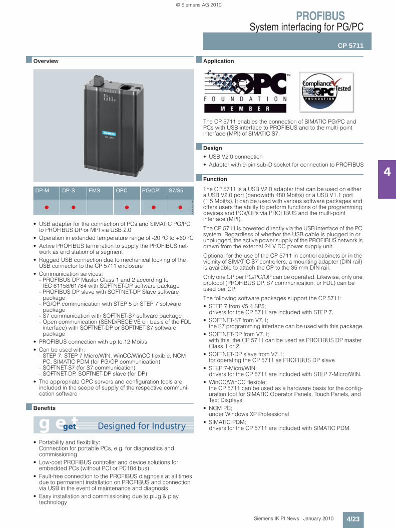
■ Overview
• USB adapter for the connection of PCs and SIMATIC PG/PC to PROFIBUS DP or MPI via USB 2.0
• Operation in extended temperature range of -20 °C to +60 °C• Active PROFIBUS termination to supply the PROFIBUS net-
work as end station of a segment• Rugged USB connection due to mechanical locking of the
USB connector to the CP 5711 enclosure• Communication services:
- PROFIBUS DP Master Class 1 and 2 according to IEC 61158/61784 with SOFTNET-DP software package
- PROFIBUS DP slave with SOFTNET-DP Slave software package
- PG/OP communication with STEP 5 or STEP 7 software package
- S7 communication with SOFTNET-S7 software package- Open communication (SEND/RECEIVE on basis of the FDL
interface) with SOFTNET-DP or SOFTNET-S7 software package
• PROFIBUS connection with up to 12 Mbit/s• Can be used with:
- STEP 7, STEP 7 Micro/WIN, WinCC/WinCC flexible, NCM PC, SIMATIC PDM (for PG/OP communication)
- SOFTNET-S7 (for S7 communication)- SOFTNET-DP, SOFTNET-DP slave (for DP)
• The appropriate OPC servers and configuration tools are included in the scope of supply of the respective communi-cation software
■ Benefits
• Portability and flexibility:Connection for portable PCs, e.g. for diagnostics and commissioning
• Low-cost PROFIBUS controller and device solutions for embedded PCs (without PCI or PC104 bus)
• Fault-free connection to the PROFIBUS diagnosis at all times due to permanent installation on PROFIBUS and connection via USB in the event of maintenance and diagnosis
• Easy installation and commissioning due to plug & play technology
■ Application
The CP 5711 enables the connection of SIMATIC PG/PC and PCs with USB interface to PROFIBUS and to the multi-point interface (MPI) of SIMATIC S7.
■ Design
• USB V2.0 connection• Adapter with 9-pin sub-D socket for connection to PROFIBUS
■ Function
The CP 5711 is a USB V2.0 adapter that can be used on either a USB V2.0 port (bandwidth 480 Mbit/s) or a USB V1.1 port (1.5 Mbit/s). It can be used with various software packages and offers users the ability to perform functions of the programming devices and PCs/OPs via PROFIBUS and the multi-point interface (MPI).
The CP 5711 is powered directly via the USB interface of the PC system. Regardless of whether the USB cable is plugged in or unplugged, the active power supply of the PROFIBUS network is drawn from the external 24 V DC power supply unit.
Optional for the use of the CP 5711 in control cabinets or in the vicinity of SIMATIC S7 controllers, a mounting adapter (DIN rail) is available to attach the CP to the 35 mm DIN rail.
Only one CP per PG/PC/OP can be operated. Likewise, only one protocol (PROFIBUS DP, S7 communication, or FDL) can be used per CP.
The following software packages support the CP 5711:• STEP 7 from V5.4 SP5;
drivers for the CP 5711 are included with STEP 7.• SOFTNET-S7 from V7.1;
the S7 programming interface can be used with this package.• SOFTNET-DP from V7.1;
with this, the CP 5711 can be used as PROFIBUS DP master Class 1 or 2.
• SOFTNET-DP slave from V7.1; for operating the CP 5711 as PROFIBUS DP slave
• STEP 7-Micro/WIN; drivers for the CP 5711 are included with STEP 7-Micro/WIN.
• WinCC/WinCC flexible; the CP 5711 can be used as a hardware basis for the config-uration tool for SIMATIC Operator Panels, Touch Panels, and Text Displays.
• NCM PC; under Windows XP Professional
• SIMATIC PDM; drivers for the CP 5711 are included with SIMATIC PDM.
Kap_04_en.fm Seite 23 Freitag, 29. Januar 2010 9:52 09
© Siemens AG 2010

PROFIBUSSystem interfacing for PG/PC
CP 5711
4/24 Siemens IK PI News · January 2010
4
■ Function (continued)
Diagnostics
Numerous diagnostic tools are available for the CP 5711. For support, the module also includes comprehensive LED diagnostics. Operating and signal states can be recognized quickly via five LEDs.
Configuration • The S7 communication and open communication protocols
can be configured in STEP 7 or NCM PC.
The NCM PC configuration tool is included with the software packages SOFTNET-S7 and SOFTNET-DP for PROFIBUS.
■ Technical specifications
PC/IPC with CP 5711 and SOFTNET for PROFIBUS
S7-300with CP 342-5or CP 343-5
S7-400 withCP 443-5
PROFIBUS
G_I
K10
_XX
_500
34
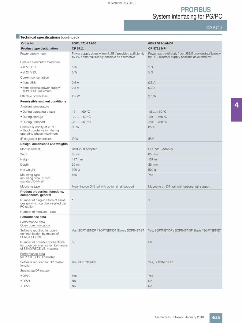
Order No. 6GK1 571-1AA00 6GK1 571-1AM00
Product type designation CP 5711 CP 5711 MPI
Data transmission rate
Data transmission rate at interface 1 in accordance with ROFIBUS
9.6 kbit/s … 12 Mbit/s 9.6 kbit/s … 12 Mbit/s
Interfaces
Number of electrical connections at interface 1 in accordance with ROFIBUS
1 1
Number of interfacesin accordance with USB
1 1
Number of electrical connections for supply voltage
1 1
Design of electrical connections
• at interface 1 in accordance with ROFIBUS
9-pin D-sub female connector (RS485) 9-pin D-sub female connector (RS485)
• for supply voltage 2-pin terminal block 2-pin terminal block
• of USB interface standard B socket standard B socket
Standard for USB 2.0 interface Yes Yes
Supply voltage, current con-sumption, power loss
Type of power supply DC DC
Type of power supply optional external supply
Yes Yes
Power supply
• from USB 5 V 5 V
• external 24 V 24 V- minimum 18 V 18 V- maximum 30 V 30 V
Kap_04_en.fm Seite 24 Freitag, 29. Januar 2010 9:52 09
© Siemens AG 2010
PROFIBUSSystem interfacing for PG/PC
CP 5711
4/25Siemens IK PI News · January 2010
4
■ Technical specifications (continued)
Order No. 6GK1 571-1AA00 6GK1 571-1AM00
Product type designation CP 5711 CP 5711 MPI
Power supply note Power supply directly from USB if provided sufficiently by PC / external supply possible as alternative
Power supply directly from USB if provided sufficiently by PC / external supply possible as alternative
Relative symmetric tolerance
• at 5 V DC 5 % 5 %
• at 24 V DC 5 % 5 %
Current consumption
• from USB 0.5 A 0.5 A
• from external power supply at 24 V DC maximum
0.3 A 0.3 A
Effective power loss 2.5 W 2.5 W
Permissible ambient conditions
Ambient temperature
• During operating phase +5 … +60 °C +5 … +60 °C
• During storage -20 … +60 °C -20 … +60 °C
• During transport -20 … +60 °C -20 … +60 °C
Relative humidity at 25 °C without condensation during operating phase, maximum
85 % 85 %
IP degree of protection IP20 IP20
Design, dimensions and weights
Module format USB V2.0 Adapter USB V2.0 Adapter
Width 85 mm 85 mm
Height 137 mm 137 mm
Depth 35 mm 35 mm
Net weight 300 g 500 g
Mounting type mounting onto 35 mm standard DIN rail
Yes Yes
Mounting type Mounting on DIN rail with optional rail support Mounting on DIN rail with optional rail support
Product properties, functions, components, general
Number of plug-in cards of same design which can be inserted per PC station
1 1
Number of modules - Note - -
Performance data
Performance dataOpen communication
Software required for open communication by means of SEND/RECEIVE
Yes, SOFTNET-DP / SOFTNET-DP Slave / SOFTNET-S7 Yes, SOFTNET-DP / SOFTNET-DP Slave / SOFTNET-S7
Number of possible connections for open communication by means of SEND/RECEIVE, maximum
50 50
Performance datafor PROFIBUS DP master
Software required for DP master function
Yes, SOFTNET-DP Yes, SOFTNET-DP
Service as DP master
• DPV0 Yes Yes
• DPV1 No No
• DPV2 No No
Kap_04_en.fm Seite 25 Freitag, 29. Januar 2010 9:52 09
© Siemens AG 2010
PROFIBUSSystem interfacing for PG/PC
CP 5711
4/26 Siemens IK PI News · January 2010
4
■ Technical specifications (continued)
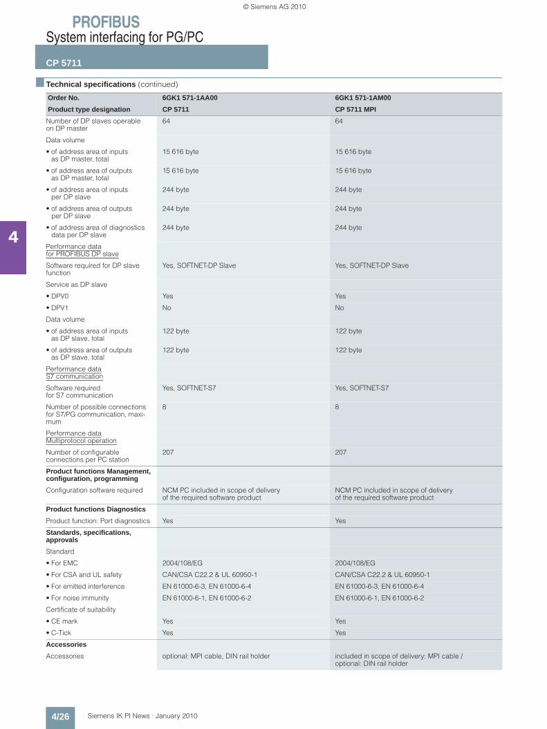
Order No. 6GK1 571-1AA00 6GK1 571-1AM00
Product type designation CP 5711 CP 5711 MPI
Number of DP slaves operableon DP master
64 64
Data volume
• of address area of inputs as DP master, total
15 616 byte 15 616 byte
• of address area of outputs as DP master, total
15 616 byte 15 616 byte
• of address area of inputs per DP slave
244 byte 244 byte
• of address area of outputsper DP slave
244 byte 244 byte
• of address area of diagnostics data per DP slave
244 byte 244 byte
Performance datafor PROFIBUS DP slave
Software required for DP slave function
Yes, SOFTNET-DP Slave Yes, SOFTNET-DP Slave
Service as DP slave
• DPV0 Yes Yes
• DPV1 No No
Data volume
• of address area of inputs as DP slave, total
122 byte 122 byte
• of address area of outputs as DP slave, total
122 byte 122 byte
Performance dataS7 communication
Software requiredfor S7 communication
Yes, SOFTNET-S7 Yes, SOFTNET-S7
Number of possible connections for S7/PG communication, maxi-mum
8 8
Performance dataMultiprotocol operation
Number of configurable connections per PC station
207 207
Product functions Management, configuration, programming
Configuration software required NCM PC included in scope of delivery of the required software product
NCM PC included in scope of delivery of the required software product
Product functions Diagnostics
Product function: Port diagnostics Yes Yes
Standards, specifications, approvals
Standard
• For EMC 2004/108/EG 2004/108/EG
• For CSA and UL safety CAN/CSA C22.2 & UL 60950-1 CAN/CSA C22.2 & UL 60950-1
• For emitted interference EN 61000-6-3, EN 61000-6-4 EN 61000-6-3, EN 61000-6-4
• For noise immunity EN 61000-6-1, EN 61000-6-2 EN 61000-6-1, EN 61000-6-2
Certificate of suitability
• CE mark Yes Yes
• C-Tick Yes Yes
Accessories
Accessories optional: MPI cable, DIN rail holder included in scope of delivery: MPI cable / optional: DIN rail holder
Kap_04_en.fm Seite 26 Freitag, 29. Januar 2010 9:52 09
© Siemens AG 2010

PROFIBUSSystem interfacing for PG/PC
CP 5711
4/27Siemens IK PI News · January 2010
4
■ Ordering data Order No. Order No.
CP 5711 communications processor
for connection of a programming device or notebook to PROFIBUS or MPI, under 32 bit in connection with PROFIBUS SOFTNET software or STEP 7; German/English
• USB V2.0 adapter 6GK1 571-1AA00
• USB V2.0 adapter CP 5711 and MPI cable, 5 m
6GK1 571-1AM00
Mounting rail support for CP 5711
6GK1 571-1AA00-0AH0
Compartment for CP 5711 enclosure; fastened mechanically to 35 mm DIN rail
SOFTNET-S7 Edition 2008
Software for S7 communication, including FDL protocol with OPC server and NCM PC; runtime software, software and electronic manual on CD-ROM, license key on USB stick, Class A, for 32 bit Windows XP Profes-sional SP2/3, Windows 2003 Server R2, SP2, Windows Vista Business/Ultimate SP1; Windows 2008 Server, for CP 5512, CP 5611, CP 5611 A2, CP 5621, CP 5711; German/English
• Single license for 1 installation 6GK1 704-5CW71-3AA0
• Software Update Servicefor 1 year, with automatic extension; requirement:Current software version
6GK1 704-5CW00-3AL0
• Upgrade of SOFTNET-S7 Edition 2006 or 2007 toSOFTNET-S7 Edition 2008
6GK1 704-5CW00-3AE0
• Upgrade of SOFTNET-S7 V6.0, V6.1, V6.2 or V6.3 to SOFTNET-S7 Edition 2008
6GK1 704-5CW00-3AE1
SOFTNET-DP Edition 2008
Software for DP protocol (Master Class 1 and 2) including FDL protocol with OPC server and NCM PC; runtime software, software and electronic manual on CD-ROM, license key on USB stick, Class A, for 32 bit, Windows XP Profes-sional SP2/3; Windows 2003 Server R2, SP2; Windows Vista Business/Ultimate SP1; Windows 2008 Server, for CP 5512, CP 5611, CP 5611 A2, CP 5621, CP 5711; German/English
• Single license for 1 installation 6GK1 704-5DW71-3AA0
• Software Update Service for 1 year, with automatic extension; requirement: Current software version
6GK1 704-5DW00-3AL0
• Upgrade of SOFTNET-DP Edition 2006 or 2007 to SOFTNET-DP Edition 2008
6GK1 704-5DW00-3AE0
• Upgrade of SOFTNET-DP V6.0, V6.1, V6.2 or V6.3 to SOFTNET-DP Edition 2008
6GK1 704-5DW00-3AE1
SOFTNET-DP Slave Edition 2008
Software for DP slave, with DP-OPC server and NCM PC; single license for 1 installation, runtime software, software and electronic manual on CD-ROM, license key on USB stick, Class A for 32 bit Windows XP Professional SP2/3; Windows 2003 Server R2, SP2; Windows Vista Business/Ultimate SP1; Windows 2008 Server; for CP 5512, CP 5611, CP 5611 A2, CP 5621, CP 5711; German/English
• Single license for 1 installation 6GK1 704-5SW71-3AA0
• Software Update Service for 1 year, with automatic extension; requirement: Current software version
6GK1 704-5SW00-3AL0
• Upgrade of SOFTNET-DP Slave Edition 2006 or 2007 to SOFTNET-DP Slave Edition 2008
6GK1704-5SW00-3AE0
• Upgrade of SOFTNET-DP Slave V6.0, V6.1, V6.2 or V6.3 to SOFTNET-DP Slave Edition 2008
6GK1704-5SW00-3AE1
PROFIBUS FastConnect bus connector RS485 Plug 180
6GK1 500-0FC10
with 180° cable outlet
Kap_04_en.fm Seite 27 Freitag, 29. Januar 2010 9:52 09
© Siemens AG 2010
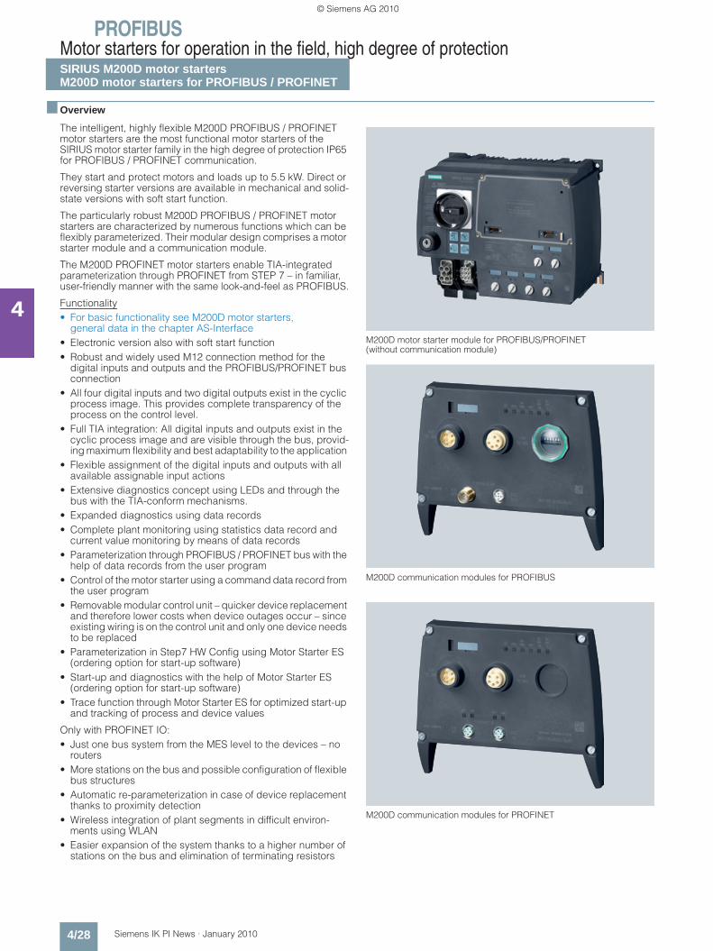
PROFIBUSMotor starters for operation in the field, high degree of protectionSIRIUS M200D motor startersM200D motor starters for PROFIBUS / PROFINET
4/28 Siemens IK PI News · January 2010
4
■ Overview
The intelligent, highly flexible M200D PROFIBUS / PROFINET motor starters are the most functional motor starters of the SIRIUS motor starter family in the high degree of protection IP65 for PROFIBUS / PROFINET communication.
They start and protect motors and loads up to 5.5 kW. Direct or reversing starter versions are available in mechanical and solid-state versions with soft start function.
The particularly robust M200D PROFIBUS / PROFINET motor starters are characterized by numerous functions which can be flexibly parameterized. Their modular design comprises a motor starter module and a communication module.
The M200D PROFINET motor starters enable TIA-integrated parameterization through PROFINET from STEP 7 – in familiar, user-friendly manner with the same look-and-feel as PROFIBUS.
Functionality• For basic functionality see M200D motor starters,
general data in the chapter AS-Interface• Electronic version also with soft start function • Robust and widely used M12 connection method for the
digital inputs and outputs and the PROFIBUS/PROFINET bus connection
• All four digital inputs and two digital outputs exist in the cyclic process image. This provides complete transparency of the process on the control level.
• Full TIA integration: All digital inputs and outputs exist in the cyclic process image and are visible through the bus, provid-ing maximum flexibility and best adaptability to the application
• Flexible assignment of the digital inputs and outputs with all available assignable input actions
• Extensive diagnostics concept using LEDs and through the bus with the TIA-conform mechanisms.
• Expanded diagnostics using data records• Complete plant monitoring using statistics data record and
current value monitoring by means of data records• Parameterization through PROFIBUS / PROFINET bus with the
help of data records from the user program• Control of the motor starter using a command data record from
the user program• Removable modular control unit – quicker device replacement
and therefore lower costs when device outages occur – since existing wiring is on the control unit and only one device needs to be replaced
• Parameterization in Step7 HW Config using Motor Starter ES (ordering option for start-up software)
• Start-up and diagnostics with the help of Motor Starter ES (ordering option for start-up software)
• Trace function through Motor Starter ES for optimized start-up and tracking of process and device values
Only with PROFINET IO:• Just one bus system from the MES level to the devices – no
routers • More stations on the bus and possible configuration of flexible
bus structures• Automatic re-parameterization in case of device replacement
thanks to proximity detection• Wireless integration of plant segments in difficult environ-
ments using WLAN • Easier expansion of the system thanks to a higher number of
stations on the bus and elimination of terminating resistors
M200D motor starter module for PROFIBUS/PROFINET (without communication module)
M200D communication modules for PROFIBUS
M200D communication modules for PROFINET
Kap_04_en.fm Seite 28 Freitag, 29. Januar 2010 9:52 09
© Siemens AG 2010

PROFIBUSMotor starters for operation in the field, high degree of protection
SIRIUS M200D motor startersM200D motor starters for PROFIBUS / PROFINET
4/29Siemens IK PI News · January 2010
4
■ Overview (continued)
Mounting and installation
The M200D PROFIBUS / PROFINET motor starter consists of a communication module and a motor starter module. Only the motor starter module has to be replaced therefore when replac-ing devices. This saves time and money. The communication module remains as an active station on the bus and all other system components continue running. This prevents downtimes.
The integrated plug-in technology enables far lower wiring out-lay: Connecting cables can be plugged directly onto the motor starter module. The PROFINET bus is connected cost-effectively using an M12 connection on the device. All versions have iden-tical enclosure dimensions for easier system design and conver-sion.
Parameterization and configuration
All motor protection functions, limit values and reactions can be defined by parameterization.
The user has several user-friendly options for the parameteriza-tion. In addition to parameterization directly from STEP 7, which also permits automatic re-parameterization in case of device re-placement, it is possible to use the user-friendly Motor Starter ES start-up software. By connecting a programming device directly to PROFIBUS / PROFINET and the Motor Starter ES start-up soft-ware, the devices can also be conveniently programmed from a central point through the bus. Also, parameters can be changed during operation from the user program using the data record mechanism so that the function of the motor starter is adapted to the process when required. With the help of a PC and the Motor Starter ES software it is also possible to perform the parameter-ization through the local point-to-point interface on-site.
Functions can be flexibly assigned to the digital inputs and outputs, adapting them to all possible conveyor applications. All digital inputs and outputs exist in the cyclic process image. All limit values for monitoring functions and their reactions are parameterizable and therefore adaptable to the application. Consistency with other products of the SIRIUS M200D motor starter range and with the frequency converter and ET 200pro peripherals system is assured.
Only with the M200D PROFINET motor starter
Thanks to the integrated proximity detection, the device name does not need to be issued manually when a device is replaced. The name is issued automatically by the neighboring devices which note the "names" of the devices in their proximity. No additional start-up measures are required therefore when replacing a device.
The new motor starter generation is characterized by high func-tionality, maximum flexibility and the highest level of automation. The PROFINET is recommended in particular for expansive and highly automated system components because the possibility of monitoring devices and systems with data records (statistical data, measured values and device diagnostics) guarantees an in-depth view of the plant from the control room and therefore in-creases plant availability.
Operation
The motor starters record the actual current flow. Evaluating the current of the parameterizable solid-state overload protection increases the availability of the drives, as do reliable messages concerning the overranging or underranging of setpoint values.
Diagnostics and maintenance
Diagnostics is provided through numerous mechanisms – and can be used as the customer prefers.
The motor starter is TIA-diagnostics compatible, which means that when a fault is identified, a diagnostics alarm is distributed, which invokes the diagnostics-OB with a SIMATIC control. The fault can be evaluated as usual in the user program.
The M200D motor starter offers a large variety of diagnostics data through data records. Its functionality is without equal on the market. There are extensive options for reading out data from the motor starter for monitoring devices, systems or processes.
The motor starter is equipped internally with 3 logbooks for device faults, motor starter trips and events, which are issued with a time stamp. These logbooks can be read out of the motor starter at any time in the form of data records and provide the plant operator with plenty of information about the state of his plant and process which he can use to carry out improvements.
With the slave pointer and statistical data functions it is possible to read out, for example, the maximum internal current values or the number of motor starter connection operations for plant monitoring purposes. This enables process deviations to be monitored or commissioning to be optimized. The user can draw conclusions about the actual load conditions of the devices in his process and on this basis can optimize his plant mainte-nance intervals.
The device diagnostics data record contains details of all the states of the motor starter, the device configuration and the com-munication as a basis for central device and plant monitoring.
With installation and maintenance functions (I&M), information (I&M) on modules employed is stored in the motor starter on the one hand, and on the other, data (I&M), which can be specified by the user during configuration, such as location designations. I&M functions serve for troubleshooting faults and localizing changes in hardware at a plant or checking the system configu-ration. Reordering a device is particularly easy as the result.
The integrated maintenance timer can be used to implement preventative maintenance and avoid plant downtimes through look-ahead servicing.
Another new feature is the integrated TRACE function with the Motor Starter ES software. It can be used to record measured values as a function of time following a trigger event. This en-ables process flows to be recorded and their timing optimized.
Local control of a drive is possible using the ordering option with integrated manual operation. This is yet another new develop-ment which distinguishes the M200D PROFIBUS / PROFINET motor starter from the rest of the market and adds innovative technology, maximum availability and transparency to the system.
See from page 5/7 for the Motor Starter ES software.
Kap_04_en.fm Seite 29 Freitag, 29. Januar 2010 9:52 09
© Siemens AG 2010
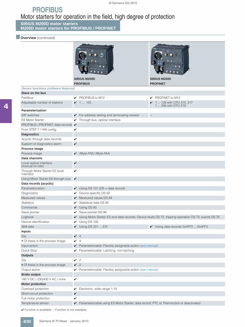
PROFIBUSMotor starters for operation in the field, high degree of protectionSIRIUS M200D motor startersM200D motor starters for PROFIBUS / PROFINET
4/30 Siemens IK PI News · January 2010
4
■ Overview (continued)
SIRIUS M200D SIRIUS M200D
PROFIBUS PROFINET
Device functions (software features)Slave on the bus
Fieldbus ✔ PROFIBUS to M12 ✔ PROFINET to M12
Adjustable number of stations ✔ 1 .... 125 ✔ 1 ... 128 with CPU 315, 3171 ... 256 with CPU 319
Parameterization
DIP switches ✔ For address setting and terminating resistor --
ES Motor Starter ✔ Through bus, optical interface
PROFIBUS / PROFINET data records ✔
From STEP 7 / HW config ✔
Diagnostics
Acyclic through data records ✔
Support of diagnostics alarm ✔
Process image
Process image ✔ 2Byte PAE/ 2Byte PAA
Data channels
Local optical interface (manual on-site)
✔
Through Motor Starter ES local interface
✔
Using Motor Starter ES through bus ✔
Data records (acyclic)
Parameterization ✔ Using DS 131 (DS = data record)
Diagnostics ✔ Device-specific DS 92
Measured values ✔ Measured values DS 94
Statistics ✔ Statistical data DS 95
Commands ✔ Using DS 93
Slave pointer ✔ Slave pointer DS 96
Logbook ✔ Using Motor Starter ES and data records: Device faults DS 72, tripping operation DS 73, events DS 75
Device identification ✔ Using DS 100
I&M data ✔ Using DS 231 ... 234 ✔ Using data records 0xAFF0 ... 0xAFF3
Inputs
Qty ✔ 4
• Of these in the process image ✔ 4
Input action ✔ Parameterizable: Flexibly assignable action (see manual)
Quick-Stop ✔ Parameterizable: Latching, non-latching
Outputs
Qty ✔ 2
• Of these in the process image ✔ 2
Output action ✔ Parameterizable: Flexibly assignable action (see manual)
Brake output
180 V DC / 230/400 V AC / none ✔
Motor protection
Overload protection ✔ Electronic, wide range 1:10
Short-circuit protection ✔
Full motor protection ✔
Temperature sensor ✔ Parameterizable using ES Motor Starter, data record: PTC or Thermoclick or deactivated
✔ Function is available; -- Function is not available.
Kap_04_en.fm Seite 30 Freitag, 29. Januar 2010 9:52 09
© Siemens AG 2010

PROFIBUSMotor starters for operation in the field, high degree of protection
SIRIUS M200D motor startersM200D motor starters for PROFIBUS / PROFINET
4/31Siemens IK PI News · January 2010
4
■ Overview (continued)
■ Application
The M200D PROFIBUS / PROFINET motor starters are particu-larly suitable for fully TIA-integrated, highly automated conveyor applications which meet all needs with regard to the monitoring of devices and systems and preventative maintenance. Adaptability of the motor starter functions and maximum flexibil-ity of the device enable a broad range of application without any limits. The PROFINET-specific expansions are the best assur-ance of a future-proof investment.
SIRIUS M200D SIRIUS M200D
PROFIBUS PROFINET
Device functions (software features)Device functions
Repair switch ✔
Current limit monitoring bottom ✔ Parameterizable
Current limit monitoring top ✔ Parameterizable
Zero current detection ✔ Parameterizable: tripping, warning
Blocking current ✔ Parameterizable
Unbalance ✔ Parameterizable
Load type ✔ Parameterizable: single- and three-phase
Shutdown class ✔ Parameterizable using ES Motor Starter, data record: Class 5, 10, 15, 20
Protection against voltage failure ✔ Parameterizable: Activated/deactivated
Soft starter control function
Soft start function ✔
Bypass function ✔ Only electronic version
✔ Function is available; -- Function is not available.
Kap_04_en.fm Seite 31 Freitag, 29. Januar 2010 9:52 09
© Siemens AG 2010
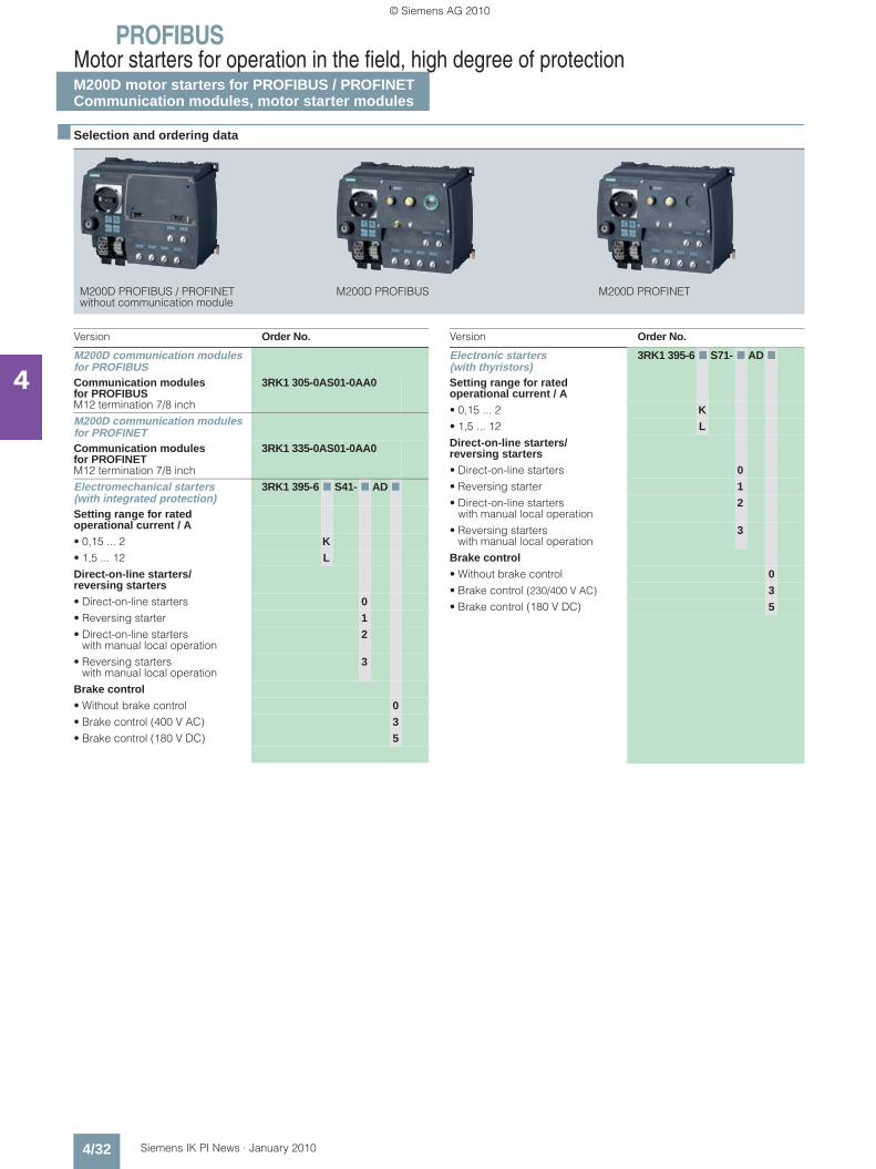
PROFIBUSMotor starters for operation in the field, high degree of protectionM200D motor starters for PROFIBUS / PROFINETCommunication modules, motor starter modules
4/32 Siemens IK PI News · January 2010
4
■ Selection and ordering data
M200D PROFIBUS / PROFINET M200D PROFIBUS M200D PROFINETwithout communication module
Version Order No.
M200D communication modules for PROFIBUS Communication modules for PROFIBUSM12 termination 7/8 inch
3RK1 305-0AS01-0AA0
M200D communication modules for PROFINET Communication modules for PROFINETM12 termination 7/8 inch
3RK1 335-0AS01-0AA0
Electromechanical starters (with integrated protection)
3RK1 395-6 7 S41- 7 AD 7
Setting range for rated operational current / A• 0,15 ... 2 K• 1,5 ... 12 LDirect-on-line starters/reversing starters• Direct-on-line starters 0• Reversing starter 1• Direct-on-line starters
with manual local operation2
• Reversing starters with manual local operation
3
Brake control• Without brake control 0• Brake control (400 V AC) 3• Brake control (180 V DC) 5
Version Order No.
Electronic starters (with thyristors)
3RK1 395-6 7 S71- 7 AD 7
Setting range for rated operational current / A• 0,15 ... 2 K• 1,5 ... 12 LDirect-on-line starters/reversing starters• Direct-on-line starters 0• Reversing starter 1• Direct-on-line starters
with manual local operation2
• Reversing starters with manual local operation
3
Brake control• Without brake control 0• Brake control (230/400 V AC) 3• Brake control (180 V DC) 5
Kap_04_en.fm Seite 32 Freitag, 29. Januar 2010 9:52 09
© Siemens AG 2010
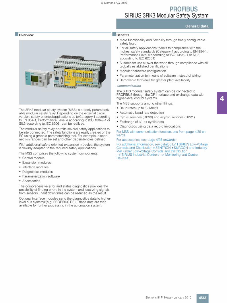
PROFIBUSSIRIUS 3RK3 Modular Safety System
General data
4/33Siemens IK PI News · January 2010
4
■ Overview
The 3RK3 modular safety system (MSS) is a freely parameteriz-able modular safety relay. Depending on the external circuit version, safety-oriented applications up to Category 4 according to EN 954-1, Performance Level e according to ISO 13849-1 or SIL3 according to IEC 62061 can be realized.
The modular safety relay permits several safety applications to be interconnected. The safety functions are easily created on the PC using a graphic parameterizing tool. For example, discon-nection ranges can be set and other dependencies defined.
With additional safety-oriented expansion modules, the system is flexibly adapted to the required safety applications.
The MSS comprises the following system components:• Central module• Expansion modules• Interface modules• Diagnostics modules• Parameterization software• Accessories
The comprehensive error and status diagnostics provides the possibility of finding errors in the system and localizing signals from sensors. Plant downtimes can be reduced as the result.
Optional interface modules send the diagnostics data to higher-level bus systems (e.g. PROFIBUS DP). These data are then available for further processing in the automation system.
■ Benefits
• More functionality and flexibility through freely configurable safety logic
• For all safety applications thanks to compliance with the highest safety standards (Category 4 according to EN 954-1, Performance Level e according to ISO 13849-1 or SIL3 according to IEC 62061)
• Suitable for use all over the world through compliance with all globally established certifications
• Modular hardware configuration • Parameterization by means of software instead of wiring• Removable terminals for greater plant availability
Communication
The 3RK3 modular safety system can be connected to PROFIBUS through the DP interface and exchange data with higher-level control systems.
The MSS supports among other things:• Baud rates up to 12 Mbit/s • Automatic baud rate detection• Cyclic services (DPV0) and acyclic services (DPV1)• Exchange of 32-bit cyclic data• Diagnostics using data record invocations
For MSS with communication function, see from page 4/35 on-wards.For accessories, see page 4/36 onwards.For additional information, see catalog LV 1 SIRIUS Low-Voltage Controls and Distribution • SENTRON • SIVACON and Industry Mall under Low-Voltage Controls and Distribution --> SIRIUS Industrial Controls --> Monitoring and Control Devices.
Kap_04_en.fm Seite 33 Freitag, 29. Januar 2010 9:52 09
© Siemens AG 2010
PROFIBUSSIRIUS 3RK3 Modular Safety System
General data
4/34 Siemens IK PI News · January 2010
4
■ Application
The 3RK3 modular safety system can be used for all safety-oriented requirements in the manufacturing industry and offers the following safety functions:• EMERGENCY-STOP:
With this function, signals from EMERGENCY-STOP devices with positive-opening contacts are evaluated.
• Protective door monitoring: Signals from protective doors or protective flaps with positive opening contacts or an NC-NO combination are evaluated.
• Non-contact protective devices (BWS):Signals from e.g. light curtains and laser scanners are evaluated.
• Switching mats:Signals from switching mats with NC contacts or crossover monitoring are evaluated.
• Two-hand operator controls:With this function, signals from a two-hand operator control device are evaluated.
• OK buttons:Signals from OK buttons with NO contact are evaluated.
• Operating mode selector switches:With this function, signals from an operating mode selector switch with NO contacts are evaluated. Up to 5 operating modes can be defined. The operating mode to be imple-mented can be freely configured in the downstream logic.
• Logic operation functions:AND, OR, XOR, NAND, NOR, negation (NEG), flip-flop (FF-RS)
• Counter functions:- The safety relay supports the counting function
"counter 0 -> 1". The count value is changed only when there is a positive edge at the count inputs. The current count value can be counted forwards or backwards through one own count input each.
- The safety relay supports the counting function "For negative edge 1 -> 0". The count value is changed only when there is a negative edge. The current count value can be counted forwards or backwards through one own count input each.
- The safety relay supports the counting function"For both edges". The count value is changed both when there is a positive edge and when there is a negative edge. The cur-rent count value can be counted forwards or backwards through one own count input each.
• Time functions:ON delay, On delay (trigger), passing make contact, passing make contact (trigger), OFF delay, OFF delay (trigger), clock-pulsing.
• Start functions:Manual and automatic start
• Output functions:Standard outputs and fail-safe outputs can be actuated.
Kap_04_en.fm Seite 34 Freitag, 29. Januar 2010 9:52 09
© Siemens AG 2010
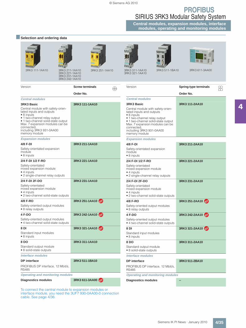
PROFIBUSSIRIUS 3RK3 Modular Safety System
Central modules, expansion modules, interfacemodules, operating and monitoring modules
4/35Siemens IK PI News · January 2010
4
■ Selection and ordering data
To connect the central module to expansion modules or interface module, you need the 3UF7 930-0AA00-0 connection cable. See page 4/36.
3RK3 111-1AA10 3RK3 211-1AA103RK3 221-1AA103RK3 231-1AA103RK3 242-1AA10
3RK3 311-1AA103RK3 321-1AA10
3RK3 511-1BA103RK3 251-1AA10 3RK3 611-3AA00
Version Screw terminals
Order No.
Central modules
3RK3 Basic 3RK3 111-1AA10Central module with safety-orien-tated inputs and outputs• 8 inputs• 1 two-channel relay output• 1 two-channel solid-state outputMax. 7 expansion modules can be connected,including 3RK3 931-0AA00 memory module
Expansion modules
4/8 F-DI 3RK3 211-1AA10
Safety-orientated expansion module• 8 inputs
2/4 F-DI 1/2 F-RO 3RK3 221-1AA10
Safety-orientated mixed expansion module• 4 inputs• 2 single-channel relay outputs
2/4 F-DI 2F-DO 3RK3 231-1AA10
Safety-orientated mixed expansion module• 4 inputs• 2 two-channel solid-state outputs
4/8 F-RO 3RK3 251-1AA10
Safety-oriented output modules• 8 relay outputs
4 F-DO 3RK3 242-1AA10
Safety-oriented output modules• 4 two-channel solid-state outputs
8 DI 3RK3 321-1AA10
Standard input modules• 8 inputs
8 DO 3RK3 311-1AA10
Standard output module• 8 solid-state outputs
Interface modules
DP interface 3RK3 511-1BA10
PROFIBUS DP interface, 12 Mbit/s, RS485
Operating and monitoring modules
Diagnostics modules 3RK3 611-3AA00
N
N
N
N
Version Spring-type terminals
Order No.
Central modules
3RK3 Basic 3RK3 111-2AA10
Central module with safety-orien-tated inputs and outputs• 8 inputs• 1 two-channel relay output• 1 two-channel solid-state outputMax. 7 expansion modules can be connected,including 3RK3 931-0AA00 memory module
Expansion modules
4/8 F-DI 3RK3 211-2AA10
Safety-orientated expansion module• 8 inputs
2/4 F-DI 1/2 F-RO 3RK3 221-2AA10
Safety-orientated mixed expansion module• 4 inputs• 2 single-channel relay outputs
2/4 F-DI 2F-DO 3RK3 231-2AA10
Safety-orientated mixed expansion module• 4 inputs• 2 two-channel solid-state outputs
4/8 F-RO 3RK3 251-2AA10
Safety-oriented output modules• 8 relay outputs
4 F-DO 3RK3 242-2AA10
Safety-oriented output modules• 4 two-channel solid-state outputs
8 DI 3RK3 321-2AA10
Standard input modules• 8 inputs
8 DO 3RK3 311-2AA10
Standard output module• 8 solid-state outputs
Interface modules
DP interface 3RK3 511-2BA10
PROFIBUS DP interface, 12 Mbit/s, RS485
Operating and monitoring modules
Diagnostics modules --
N
N
N
Kap_04_en.fm Seite 35 Dienstag, 2. Februar 2010 5:22 17
© Siemens AG 2010
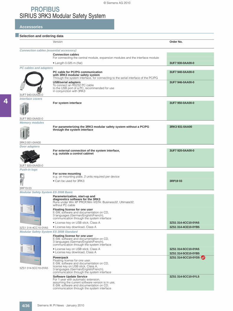
PROFIBUSSIRIUS 3RK3 Modular Safety System
Accessories
4/36 Siemens IK PI News · January 2010
4
■ Selection and ordering data
Version Order No.
Connection cables (essential accessory)Connection cablesFor connecting the central module, expansion modules and the interface module
• Length 0.025 m (flat) 3UF7 930-0AA00-0
PC cables and adapters
3UF7 940-0AA00-0
PC cable for PC/PG communication with 3RK3 modular safety systemThrough the system interface, for connecting to the serial interface of the PC/PG
3UF7 940-0AA00-0
USB/serial adaptersTo connect an RS232 PC cable to the USB port of a PC, recommended for use in conjunction with 3RK3
3UF7 946-0AA00-0
Interface covers
3UF7 950-0AA00-0
For system interface 3UF7 950-0AA00-0
Memory modules
3RK3 931-0AA00
For parameterizing the 3RK3 modular safety system without a PC/PG through the system interface
3RK3 931-0AA00
Door adapters
3UF7 920-0AA00-0
For external connection of the system interface, e.g. outside a control cabinet
3UF7 920-0AA00-0
Push-in lugs
3RP19 03
For screw mountinge.g. on mounting plate, 2 units required per device• Can be used for 3RK3 3RP19 03
Modular Safety System ES 2008 Basic
3ZS1 314-4CC10-0YA5
Parameterization, start-up and diagnostics software for the 3RK3Runs under Win XP PROF/Win VISTA: Business32, Ultimate32; without PC cableFloating license for one userE-SW, software and documentation on CD, 3 languages (German/English/French), communication through the system interface• License key on USB stick, Class A 3ZS1 314-4CC10-0YA5• License key download, Class A 3ZS1 314-4CE10-0YB5
Modular Safety System ES 2008 Standard
3ZS1 314-5CC10-0YA5
Floating license for one userE-SW, software and documentation on CD, 3 languages (German/English/French), communication through the system interface• License key on USB stick, Class A 3ZS1 314-5CC10-0YA5• License key download, Class A 3ZS1 314-5CE10-0YB5Powerpack Floating license for one user,E-SW, software and documentation on CD, license key on USB stick, Class A, 3 languages (German/English/French), communication through the system interface
3ZS1 314-5CC10-0YD5
Software Update Service For 1 year with automatic extension, assuming the current software version is in use, E-SW, software and documentation on CD, communication through the system interface
3ZS1 314-5CC10-0YL5
N
Kap_04_en.fm Seite 36 Freitag, 29. Januar 2010 9:52 09
© Siemens AG 2010

PROFIBUSSIRIUS 3RK3 Modular Safety System
SoftwareModular Safety System ES
4/37Siemens IK PI News · January 2010
4
■ Overview
Modular Safety System ES: the uniform software for the modular safety system
Modular Safety System ES is the engineering software for the configuration, start-up and diagnostics of the 3RK3 modular safety system. The software combines the configuring of the hardware, the programming of the safety functions, and the test-ing and diagnostics of the safety system.
Hardware configurationThe configuration defines the system's hardware layout. It lays down which modules are used in the system: A central module as a safe control system including onboard peripherals, expan-sion modules with inputs and outputs, an interface module for connecting to PROFIBUS. For better clarity, the layout is shown in a graphic presentation. For each module, it is optionally possible to issue an equipment ID which is shown in the logic diagram for identification of the inputs and outputs.
Definition of the hardware layout
Graphic parameterizing of the safety logic by Drag & DropThe functionality of the safety logic is laid down with a graphics editor designed for intuitive operation. Safe monitoring functions (EMERGENCY-STOP, non-contact protective devices/light ar-rays, protective doors, etc.), output functions and logic functions (AND/OR operations, counting function, time functions, etc.), non-safety-orientated input/output functions, device status func-tions and control functions can be dragged from the extensive functions catalog onto the work interface by Drag&Drop. Depending on the version, each function has several input and output connecting points through which the functions can be interconnected by simple mouse clicks. Double-clicking on a function symbol opens the related features dialog window in which all the parameters can be displayed and configured: Scope of the function's inputs and outputs, configuring the chan-nel type (one-channel/two-channel, NC contact/NO contact), activating the crossover monitoring, defining start options, assigning the hardware inputs and outputs, etc. Of course each function can be issued with an individual name so that e.g. the position of a safety switch in the plant can be documented.
The safety logic can be divided into several diagrams in order to enable structured processing of the entire plant. The user can freely position the functions on a quasi infinitely large drawing board, whereby the connecting lines are drawn automatically. If there is not enough space, more pages are automatically added to the diagram in horizontal or vertical direction. Connect-ing lines extending over several pages are automatically issued with cross-references during print-out. If required in the interest of clarity, the user can divide a connecting line manually into two segments, whereby the mutual reference is marked by reference arrows. For further documentation, freely compilable comment texts can be placed at any point in the diagram. Every point in the logic diagram can be processed with ease by dragging and zooming. Every project can be saved as a file and be password-protected from unauthorized access.
Processing the safety functions with the graphics editor
User prompting during start-up and maintenanceTo start up the 3RK3 modular safety system, the created project file is loaded into the device. This requires the serial interface (COM) of the PC to be connected with a special connection cable to the device. Access to the device can be password-pro-tected.After the project is loaded, the user switches the device by means of the software from configuring mode to test mode in which the safety functions are tested. Activating the diagnostics shows the status of the individual functions in the graphic logic diagram by means of different colors and symbols. In addition, the signal status of each input and output can be manually overwritten ("forcing"). If the test is completed successfully, the user releases the configuration and switches the device to protection mode, in which case "forcing" is automatically deactivated.Service personnel can activate the graphic diagnostics in pro-tection mode as well. The I&M (Identification & Maintenance) data saved in the device facilitate maintenance.
Kap_04_en.fm Seite 37 Freitag, 29. Januar 2010 9:52 09
© Siemens AG 2010

PROFIBUSSIRIUS 3RK3 Modular Safety SystemSoftwareModular Safety System ES
4/38 Siemens IK PI News · January 2010
4
■ Overview (continued)
✓ Function available
-- Function not available
More functions• The program interface language can be switched during use
between German, English and French.• A context-sensitive help function provides useful assistance
with questions concerning the use of the program.• A consistency check informs clearly about function assign-
ment errors; checks are carried out automatically when a project is saved and during the configuration test, but they can also be initially manually.
• Lists of symbols and cross-references can be issued output for effective processing of the project file.
• Standards-conform printouts:The programs of the SIRIUS ES software family make machine documentation far easier. They enable parameterization print-outs according to EN ISO 7200. The elements to be printed are easy to select and group as required.
Types of delivery and licenseModular Safety System ES 2008 is available as follows: • Floating license
- Package contains the software on CD and a floating license on a USB stick.
- The software can be installed on any number of PCs.- The floating license enables the software to be used by
1 user; after use, it can be transferred from the one PC to another.
- The CD also contains a trial license for test and evaluation purposes (free use of all program functions on any PC for a period of 14 days).
Following delivery versions are available in addition for Modular Safety System ES 2008:
• PowerpackSpecial pack for switching within the same software version to a more powerful version with more functionality, e.g. Power-pack Modular Safety System ES 2008 for switching from Basic to Standard.
• Software Update ServiceTo keep you up to date at all times, we offer a special service which supplies you automatically with all service packs and upgrades (floating license not included in delivery).
• License DownloadUser-friendly license key download from our Mall (currently only for customers from Germany) as an easy and quick way for you to receive additional licenses for your software.
The software can be downloaded free from the Internet (without floating license) at: support.automation.siemens.com/WW/view/en/25801078/133100
The download file also contains a trial license for test and evalu-ation purposes, which allows free use of all program functions on any PC for a period of 14 days. A floating license is needed to use the software after the 14 days.
System requirements
Modular Safety System ES Basic Standard
Access through the local interface on the device
✔ ✔
Parameter assignment ✔ ✔
Operating ✔ ✔
Diagnostics ✔ ✔
Test ✔ ✔
Integrated graphics editor ✔ ✔
Importing/exporting parameters ✔
Comparison functions ✔
Comfort functions ✔
Terminal designator ✔
Work on sub-diagrams ✔
Standards-conform printout according to EN ISO 7200
✔ ✔
Modular Safety System ES 2008 parameterization, start-up and diagnostics software for the 3RK3 modular safety system
Operating system Windows XP Professional (Service Pack 2), Windows Vista Ultimate 32/Business 32
Processor ≥ Pentium 800 MHz/≥ 1 GHz (Windows Vista)
RAM ≥ 512 MB/≥ 1 GB (Windows Vista)
Monitor resolution ≥ 1024 x 768
Free space on hard disk ≥ 280 MB
CD-ROM/DVD drive Yes (only when installing from CD)
Serial interface (COM) Yes
PC cables for PC/PG communication Yes
Kap_04_en.fm Seite 38 Freitag, 29. Januar 2010 9:52 09
© Siemens AG 2010

PROFIBUSSIRIUS 3RK3 Modular Safety System
SoftwareModular Safety System ES
4/39Siemens IK PI News · January 2010
4
■ Ordering data Order No. Order No.
Parameterization, start-up and diagnostics software for the 3RK3 modular safety system• Runs under WIN XP PROF/
Windows Vista: Ultimate 32/Business 32• Without PC cable
Modular Safety System ES 2008 Basic
Floating license for one userE-SW, software and documentation on CD, 3 languages (German/English/French), communication through system interface
• License key on USB stick, Class A, including CD
3ZS1 314-4CC10-0YA5
• License key download, Class A, no CD
3ZS1 314-4CE10-0YB5
Modular Safety System ES 2008 Standard
Floating license for one userE-SW, software and documentation on CD, 3 languages (German/English/French), communication through system interface
• License key on USB stick, Class A, including CD
3ZS1 314-5CC10-0YA5
• License key download, Class A, no CD
3ZS1 314-5CE10-0YB5
Powerpack For Modular Safety System ES 2008 BasicFloating license for one user,E-SW, software and documentation on CD, license key on USB stick, Class A, 3 languages (German/English/French), communication through the system interface
3ZS1 314-5CC10-0YD5
Software Update Service For 1 year with automatic extension, assuming the current software version is in use, E-SW, software and documentation on CD, communication through the system interface
3ZS1 314-5CC10-0YL5
Accessories
PC cables for PC/PG communicationThrough the system interface on the device, for connecting to the serial interface on the PC/PG
3UF7 940-0AA00-0
USB/serial adaptersTo connect a serial PC cable (for connection to the serial PC interface / RS 232), we recommend using modular safety system 3RK3, soft starter 3RW44, ET 200S/ECOFAST/ET 200pro motor starter, AS-i safety monitor and AS-i analyzer in conjunction with SIMOCODE pro 3UF7
3UF7 946-0AA00-0
Kap_04_en.fm Seite 39 Freitag, 29. Januar 2010 9:52 09
© Siemens AG 2010

PROFIBUSPower Management System
System overview
4/40 Siemens IK PI News · January 2010
4
■ Overview
Power Management System: Configuration and makeup of all participating components
The continuous increase in energy prices is leading to higher operating costs and can pose a threat to a company's competi-tiveness.
The goal of our Power Management System is to optimize operating costs and increase plant availability.
As part of TIA and TIP, it is fully integrated in the industrial tech-nologies of production and process automation (SIMATIC PCS 7 and SIMATIC WinCC) from Siemens. This means lower costs of implementation and all the following benefits:• Consistent product design• Standard components• Open interfaces• Uniform operating philosophy• System-tested, certified products• Global availability in high Siemens quality• Optimum support from Siemens hotline
In other words: With Power Management, you can make full use of all the potential for optimization provided by a consistent power management solution.
The power management system comprises both hardware components and software components.
Hardware components
The hardware components are:• Communication-capable measuring devices such as • SENTRON PAC3200 and SENTRON PAC4200• Switching and protection devices (3VL / 3WL) • The SIMOCODE pro motor management system• E-counters• Protection equipment such as SIPROTEC • And diverse other communication-capable devices
Software components
The software components are:• SIMATIC PCS 7 powerrate/SIMATIC WinCC powerrate
as add-ons to SIMATIC PCS 7 or SIMATIC WinCC• SIMATIC PCS 7 Library PAC3200 as driver / faceplate for
SIMATIC PCS 7• Switch ES Power
SIMATIC PCS 7 powerrate/SIMATIC WinCC powerrate
SIMATIC PCS 7 and WinCC powerrate are extensions to PCS 7 and WinCC respectively and throw light on power consumption from the infeed to the load.• Identification of power-intensive consumer devices and
processes in order to introduce measures for improving power efficiency
• Comparison of consumption profiles for greater efficiency of process design, charge-related load recording
• Optimizing the company according to energy parameters based on an assessment of consumption and costs
• Complying with the contractually agreed power limit, thus preventing higher power supply costs or penalty payments.
SIMATIC PCS 7 Library PAC3200 and PAC3200 function block library for SIMATIC WinCC
The SIMATIC PCS 7 and WinCC function block libraries for PAC3200 enable optimum integration of the SENTRON PAC3200 multifunction measuring instrument in SIMATIC PCS 7 and WinCC respectively.
■ More information
Hardware components of the Power Management System and its software components are dealt with in this chapter.
You can find more information on the Internet at:www.siemens.com/powermanagementsystem
Protection equipmente.g.SIPROTEC
SIMATIC S7
Archive Bus systems(e.g. Ethernet)
Bus systems(e.g. PROFIBUS)
Analog and digital signals from contactors, counters, flow meters,...
Powermonitoring devices, e.g. SENTRON PAC3200or SENTRON PAC4200
E-counter Circuitbreaker, e.g.SENTRON 3WL
Motormanagementsystem, e.g.SIMOCODE pro
Soft starter, e.g.SIRIUS 3RW44
Frequencyconverter, e.g.SINAMICS G120
Distributed peripheralse.g. ET 200
Operating andmonitoring level
Processing level
Data acquisition andcontrol level
OS with SIMATIC PCS 7 / WinCC, powerrate add-ons and function block libraries
Office PC Office PC via Internet
NS
H0_
0006
0b
Kap_04_en.fm Seite 40 Freitag, 29. Januar 2010 9:52 09
© Siemens AG 2010
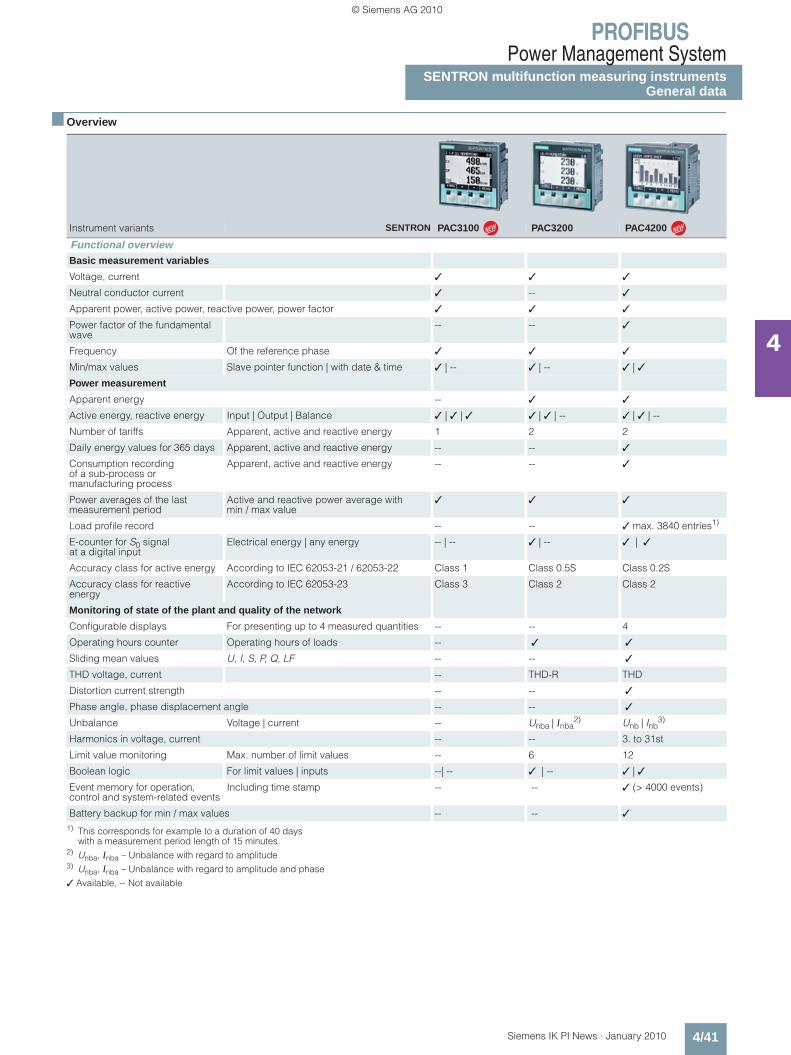
PROFIBUSPower Management System
SENTRON multifunction measuring instruments General data
4/41Siemens IK PI News · January 2010
4
■ Overview
1) This corresponds for example to a duration of 40 dayswith a measurement period length of 15 minutes.
2) Unba, Inba – Unbalance with regard to amplitude 3) Unba, Inba – Unbalance with regard to amplitude and phase
✓ Available, -- Not available
Instrument variants SENTRON PAC3100 PAC3200 PAC4200
Functional overviewBasic measurement variables
Voltage, current ✓ ✓ ✓
Neutral conductor current ✓ -- ✓
Apparent power, active power, reactive power, power factor ✓ ✓ ✓
Power factor of the fundamental wave
-- -- ✓
Frequency Of the reference phase ✓ ✓ ✓
Min/max values Slave pointer function | with date & time ✓ | -- ✓ | -- ✓ | ✓
Power measurement
Apparent energy -- ✓ ✓
Active energy, reactive energy Input | Output | Balance ✓ | ✓ | ✓ ✓ | ✓ | -- ✓ | ✓ | --
Number of tariffs Apparent, active and reactive energy 1 2 2
Daily energy values for 365 days Apparent, active and reactive energy -- -- ✓
Consumption recording of a sub-process or manufacturing process
Apparent, active and reactive energy -- -- ✓
Power averages of the last measurement period
Active and reactive power average with min / max value
✓ ✓ ✓
Load profile record -- -- ✓ max. 3840 entries1)
E-counter for S0 signalat a digital input
Electrical energy | any energy -- | -- ✓ | -- ✓ | ✓
Accuracy class for active energy According to IEC 62053-21 / 62053-22 Class 1 Class 0.5S Class 0.2S
Accuracy class for reactive energy
According to IEC 62053-23 Class 3 Class 2 Class 2
Monitoring of state of the plant and quality of the network
Configurable displays For presenting up to 4 measured quantities -- -- 4
Operating hours counter Operating hours of loads -- ✓ ✓
Sliding mean values U, I, S, P, Q, LF -- -- ✓
THD voltage, current -- THD-R THD
Distortion current strength -- -- ✓
Phase angle, phase displacement angle -- -- ✓
Unbalance Voltage | current -- Unba | Inba2) Unb | Inb
3)
Harmonics in voltage, current -- -- 3. to 31st
Limit value monitoring Max. number of limit values -- 6 12
Boolean logic For limit values | inputs --| -- ✓ | -- ✓ | ✓
Event memory for operation, control and system-related events
Including time stamp -- -- ✓ (> 4000 events)
Battery backup for min / max values -- -- ✓
N N
Kap_04_en.fm Seite 41 Freitag, 29. Januar 2010 9:52 09
© Siemens AG 2010

PROFIBUSPower Management SystemSENTRON multifunction measuring instrumentsGeneral data
4/42 Siemens IK PI News · January 2010
4
■ Overview (continued)
1) In conjunction with SENTRON PAC RS485 expansion module
✓ Available, -- Not available
Measuring precisely with SENTRON PAC3100/3200/4200 – New dimensions with the multifunction measuring instruments
The SENTRON PAC multifunction measuring instruments:PAC3200 (left), PAC3100 (center) and PAC4200 (right)
The multifunction measuring instruments of the SENTRON PAC series are used to measure and indicate all relevant network parameters in low-voltage power distribution. They can be used for single-phase measurements as well as for multiphase easurements in 3 and 4-conductor networks (TN, TT, IT).
Power values for main distribution boards, electrical feeders or individual loads are recorded precisely and reliably, and impor-tant measured values are supplied in addition for assessing the state of the plant and the quality of the network.
Instrument variants SENTRON PAC3100 PAC3200 PAC4200
Functional overviewSystem integration and communication
Ethernet (integrated) -- 10 Mbit/s 10/100 Mbit/s
• Protocol Modbus TCP -- ✓ ✓
• Gateway Ethernet <--> RS485 (Modbus) -- -- ✓1)
PROFIBUS DP (V1) -- Expansion module optional
RS485 Integrated Expansion module optional
• Protocol Modbus RTU ✓ ✓ ✓
4DI/2DO expansion module Expansion to max. 10 DI / 6 DO -- -- ✓ (max. 2 modules)
Number of expansion modules Max. -- 1 2
Integrated digital inputs (DI) Number | multifunctional 2 | -- 1 | ✓ 2 | ✓
Integrated digital outputs (DO) Number | multifunctional 2 | ✓ 1 | ✓ 2 | ✓
Installation plan
Dimensions (L x W x D) In mm 96 x 96 x 56 96 x 96 x 56 96 x 96 x 82
Mounting depth PAC | PAC with expansion module (in mm) 51 | -- 51 | 73 77 | 99
Panel cut-out (L x W) In mm 92 x 92 92 x 92 92 x 92
Standards and Approvals
CE / cULus / C-Tick / GOST ✓ ✓ ✓
IEC 61557-12 ✓ -- ✓
N N
Kap_04_en.fm Seite 42 Freitag, 29. Januar 2010 9:52 09
© Siemens AG 2010

PROFIBUSPower Management System
SENTRON multifunction measuring instrumentsGeneral data
4/43Siemens IK PI News · January 2010
4
■ Benefits
SENTRON PAC General
Performance characteristics of all multifunction measuring instruments in the SENTRON PAC series:• Simple mounting and commissioning• High IP65 degree of protection (front side, when installed)
permits usage in extremely dusty and wet environments• Intuitive operation using 4 function buttons and multilingual
plain text displays• Easy adaptation to different systems using integrated and
optional- Digital inputs and outputs- Communications interface
• Worldwide use- Min. 8 languages- International approvals- Developed and tested to European and international
standards• Low mounting depth
SENTRON PAC3200 and SENTRON PAC4200
Additional performance characteristics of the SENTRON PAC3200 and SENTRON PAC4200:• Precise energy recording• Versatile system integration
- Integrated Ethernet interface - Optional communication modules available- Multifunctional digital inputs and outputs- Limit value monitoring
• Can be connected directly to power supply networks up to 690V AC (UL-L) , CATIII without voltage transformers.
• Easy-to-use configuration software included as standard
SENTRON PAC4200
Additional performance characteristics of the SENTRON PAC4200:• Monitoring the plant status and the system quality
- Basic information for evaluating network quality - Logging of plant operations through operational, operating
and system events• Recording of the power range through power averaging
(load profile)• Daily energy meters for apparent, active and reactive energy
across 365 days for cut-off date assessment• Detection of gas, water, compressed air or other energy
sources via pulse counter to the digital inputs• Can be expanded using modules to up to 10 digital inputs and
6 digital outputs• Meters for apparent, active and reactive energy for the precise
detection of the power consumption of a partial process or manufacturing process
• 10/100 Mbit/s Ethernet interface with gateway function for the easy connection of devices with serial RS485 interface via expansion module PAC RS485 to an Ethernet network
• Comprehensive convenience indicators, such as user-defined displays, bar and status indicators, phase diagram and list and histogram graphics
• Satisfies the accuracy requirements of class 0.2S high-preci-sion meters used by power supply companies according to IEC 62053-22, which are normally reserved for exacting indus-trial applications
■ Application
Three-phase multifunction measuring instruments are used to measure and indicate all relevant network parameters of an electrical installation and they monitor these parameters perma-nently.
Applications
Wherever power has to be distributed, be it in industrial or infrastructural buildings, the SENTRON PAC supplies important information to the building services system or the power control-ling system.
The many different communication options offered by the SENTRON PAC make it an indispensable supplier of data for power management systems and for plant and building auto-mation.
Industries
Power distribution systems for the power supply are needed in all sectors of industry. SENTRON PAC is used accordingly in all sectors where power consumption and electrical parameters are to be measured.
Integration of PAC3200 and PAC4200
When the SENTRON PAC3200 and PAC4200 are fully integrated in a power management system, they monitor the power con-sumption and help to monitor the operating state of the plant. Measured values, limit value violations, operating hours of a con-nected load or power flows are supplied by the instruments quickly and reliably.
Using the optionally available interface modules, it is possible to integrate both instruments in every I&C system or every SIMATIC S7 environment.
System integration using function block libraries
Optionally available function block libraries make it easy to integrate the multifunction measuring instruments in the SIMATIC PCS 7 process control system and the SCADA-System SIMATIC WinCC. Together with the faceplates as user interface for SENTRON PAC3200, the driver blocks and diagnostics blocks in the control system enable the operating and monitor-ing of technologically important values and functions of the measuring devices in the respective target system.
Integration of the SENTRON PAC3200 in SIMATIC PCS 7/WinCC
S7 driver / components
Industrial Ethernet
PROFIBUSPROFIBUS
Faceplates
Kap_04_en.fm Seite 43 Freitag, 29. Januar 2010 9:52 09
© Siemens AG 2010

PROFIBUSPower Management SystemSENTRON multifunction measuring instrumentsGeneral data
4/44 Siemens IK PI News · January 2010
4
■ Application (continued)
System integration of RS485 field bus devices through Ethernet
A special feature is the integrated gateway function of the SENTRON PAC4200. It enables a cost-effective and simple connection of devices with an RS485 interface to an Ethernet network.
Everything required is provided by the SENTRON PAC RS485 expansion module, to which a maximum of 31 lower-level devices can be connected without a repeater and as many as 247 with a repeater.
The gateway function of the SENTRON PAC4200 supports the Modbus protocol and can be parameterized using SENTRON powerconfig.
Connecting Modbus-RTU devices to a power management system through PAC4200
■ More information
More information is available on the Internet at www.siemens.com/powermanagementsystem
Power monitoring devices
SENTRON PAC4200with gateway
SQL database
SENTRON WLSENTRON VL
SENTRONPAC3200
NS
G0_
0023
8a
ClientClientServer
Ethernet
Modbus RTU
Kap_04_en.fm Seite 44 Freitag, 29. Januar 2010 9:52 09
© Siemens AG 2010
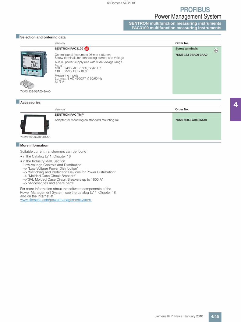
PROFIBUSPower Management System
SENTRON multifunction measuring instrumentsPAC3100 multifunction measuring instruments
4/45Siemens IK PI News · January 2010
4
■ Selection and ordering data
■ Accessories
■ More information
Suitable current transformers can be found• in the Catalog LV 1, Chapter 16• in the Industry Mall, Section
"Low-Voltage Controls and Distribution" --> "Low-Voltage Power Distribution"--> "Switching and Protection Devices for Power Distribution" --> "Molded Case Circuit Breakers" -->"3VL Molded Case Circuit Breakers up to 1600 A"--> "Accessories and spare parts"
For more information about the software components of the Power Management System, see the catalog LV 1, Chapter 18 and on the Internet atwww.siemens.com/powermanagementsystem
Version Order No.
7KM3 133-0BA00-3AA0
SENTRON PAC3100 Screw terminals
Control panel instrument 96 mm x 96 mmScrew terminals for connecting current and voltageAC/DC power supply unit with wide voltage range UAUX: 100 … 240 V AC ±10 %, 50/60 Hz 110 … 250 V DC ±10 %Measuring inputsUe: max. 3 AC 480/277 V, 50/60 Hz Ie: /5 A
7KM3 133-0BA00-3AA0
Version Order No.
7KM9 900-0YA00-0AA0
SENTRON PAC TMP
Adapter for mounting on standard mounting rail 7KM9 900-0YA00-0AA0
N
Kap_04_en.fm Seite 45 Freitag, 29. Januar 2010 9:52 09
© Siemens AG 2010
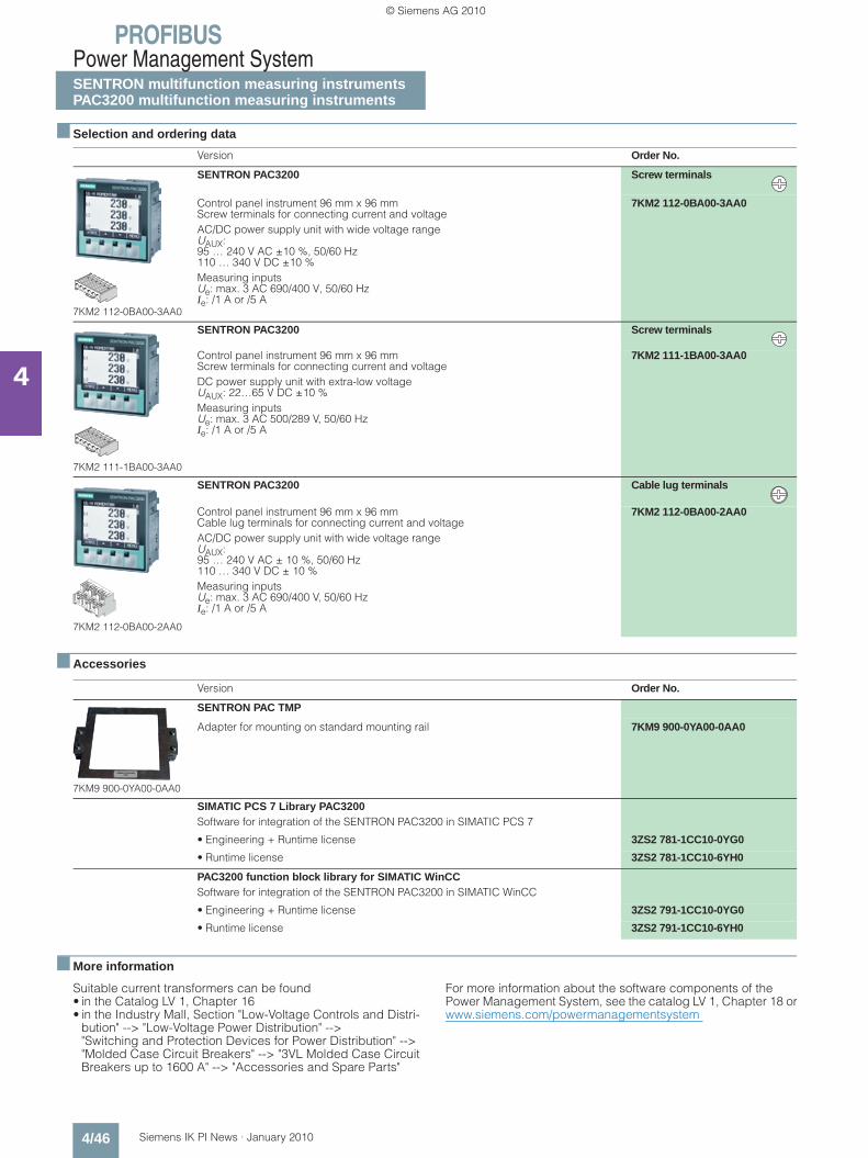
PROFIBUSPower Management SystemSENTRON multifunction measuring instrumentsPAC3200 multifunction measuring instruments
4/46 Siemens IK PI News · January 2010
4
■ Selection and ordering data
■ Accessories
■ More information
Suitable current transformers can be found• in the Catalog LV 1, Chapter 16• in the Industry Mall, Section "Low-Voltage Controls and Distri-
bution" --> "Low-Voltage Power Distribution" --> "Switching and Protection Devices for Power Distribution" --> "Molded Case Circuit Breakers" --> "3VL Molded Case Circuit Breakers up to 1600 A" --> "Accessories and Spare Parts"
For more information about the software components of the Power Management System, see the catalog LV 1, Chapter 18 orwww.siemens.com/powermanagementsystem
Version Order No.
7KM2 112-0BA00-3AA0
SENTRON PAC3200 Screw terminals
Control panel instrument 96 mm x 96 mmScrew terminals for connecting current and voltageAC/DC power supply unit with wide voltage rangeUAUX: 95 … 240 V AC ±10 %, 50/60 Hz 110 … 340 V DC ±10 %Measuring inputsUe: max. 3 AC 690/400 V, 50/60 Hz Ie: /1 A or /5 A
7KM2 112-0BA00-3AA0
7KM2 111-1BA00-3AA0
SENTRON PAC3200 Screw terminals
Control panel instrument 96 mm x 96 mmScrew terminals for connecting current and voltageDC power supply unit with extra-low voltageUAUX: 22…65 V DC ±10 %Measuring inputsUe: max. 3 AC 500/289 V, 50/60 HzIe: /1 A or /5 A
7KM2 111-1BA00-3AA0
7KM2 112-0BA00-2AA0
SENTRON PAC3200 Cable lug terminals
Control panel instrument 96 mm x 96 mmCable lug terminals for connecting current and voltageAC/DC power supply unit with wide voltage rangeUAUX:95 … 240 V AC ± 10 %, 50/60 Hz 110 … 340 V DC ± 10 %Measuring inputsUe: max. 3 AC 690/400 V, 50/60 HzIe: /1 A or /5 A
7KM2 112-0BA00-2AA0
Version Order No.
7KM9 900-0YA00-0AA0
SENTRON PAC TMP
Adapter for mounting on standard mounting rail 7KM9 900-0YA00-0AA0
SIMATIC PCS 7 Library PAC3200 Software for integration of the SENTRON PAC3200 in SIMATIC PCS 7
• Engineering + Runtime license 3ZS2 781-1CC10-0YG0
• Runtime license 3ZS2 781-1CC10-6YH0
PAC3200 function block library for SIMATIC WinCC Software for integration of the SENTRON PAC3200 in SIMATIC WinCC
• Engineering + Runtime license 3ZS2 791-1CC10-0YG0
• Runtime license 3ZS2 791-1CC10-6YH0
Kap_04_en.fm Seite 46 Freitag, 29. Januar 2010 9:52 09
© Siemens AG 2010
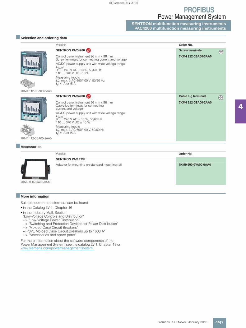
PROFIBUSPower Management System
SENTRON multifunction measuring instrumentsPAC4200 multifunction measuring instruments
4/47Siemens IK PI News · January 2010
4
■ Selection and ordering data
■ Accessories
■ More information
Suitable current transformers can be found• in the Catalog LV 1, Chapter 16• in the Industry Mall, Section
"Low-Voltage Controls and Distribution" --> "Low-Voltage Power Distribution"--> "Switching and Protection Devices for Power Distribution" --> "Molded Case Circuit Breakers" -->"3VL Molded Case Circuit Breakers up to 1600 A"--> "Accessories and spare parts"
For more information about the software components of the Power Management System, see the catalog LV 1, Chapter 18 orwww.siemens.com/powermanagementsystem
Version Order No.
7KM4 112-0BA00-3AA0
SENTRON PAC4200 Screw terminals
Control panel instrument 96 mm x 96 mmScrew terminals for connecting current and voltageAC/DC power supply unit with wide voltage rangeUAUX: 95 … 240 V AC ±10 %, 50/60 Hz 110 … 340 V DC ±10 %Measuring inputsUe: max. 3 AC 690/400 V, 50/60 Hz Ie: /1 A or /5 A
7KM4 212-0BA00-3AA0
7KM4 112-0BA00-2AA0
SENTRON PAC4200 Cable lug terminals
Control panel instrument 96 mm x 96 mmCable lug terminals for connecting current and voltageAC/DC power supply unit with wide voltage rangeUAUX:95 … 240 V AC ± 10 %, 50/60 Hz 110 … 340 V DC ± 10 %Measuring inputsUe: max. 3 AC 690/400 V, 50/60 HzIe: /1 A or /5 A
7KM4 212-0BA00-2AA0
Version Order No.
7KM9 900-0YA00-0AA0
SENTRON PAC TMP
Adapter for mounting on standard mounting rail 7KM9 900-0YA00-0AA0
NS
G0_
0023
0
N
N
Kap_04_en.fm Seite 47 Freitag, 29. Januar 2010 9:52 09
© Siemens AG 2010

PROFIBUSPower Management SystemSENTRON multifunction measuring InstrumentsPAC PROFIBUS DP expansion modules
4/48 Siemens IK PI News · January 2010
4
■ Overview
SENTRON PAC PROFIBUS DP expansion module
The PAC PROFIBUS DP expansion module has the following features:• Pluggable PROFIBUS DP communication modules for
SENTRON PAC3200 and PAC4200 multifunction measuring instruments
• Parameterizable from the front of the device or using parame-terization software
• Using PROFIBUS DPV1, data can be transferred in both cyclic and acyclic modes
• Easy integration using GSD file, with free choice of the measurement variables to be transmitted
• Plug and play• All baud rates from 9.6 Kbit/s to 12 Mbit/s are supported• Connection through 9-pole Sub-D connector according to
IEC 61158• No external auxiliary power necessary• Additional display via the device display and via LEDs on the
module
■ Application
The SENTRON PAC PROFIBUS DP communication module is plugged onto the rear of the multifunction measuring instrument. The device identifies the module automatically and presents the parameters of relevance for this module for selection in the parameterization menu.
All individual measurement variables supplied by the SENTRON PAC multifunction measuring instruments are se-lected and cyclically transmitted by means of the GSD file.This permits the optimum use of the PROFIBUS Master process image.
■ Selection and ordering data
Version Order No.
7KM9 300-0AB00-0AA0
PAC PROFIBUS DP
Expansion module for SENTRON PAC3200 and PAC4200(PROFIBUS DP V1)
7KM9 300-0AB00-0AA0
Kap_04_en.fm Seite 48 Freitag, 29. Januar 2010 9:52 09
© Siemens AG 2010
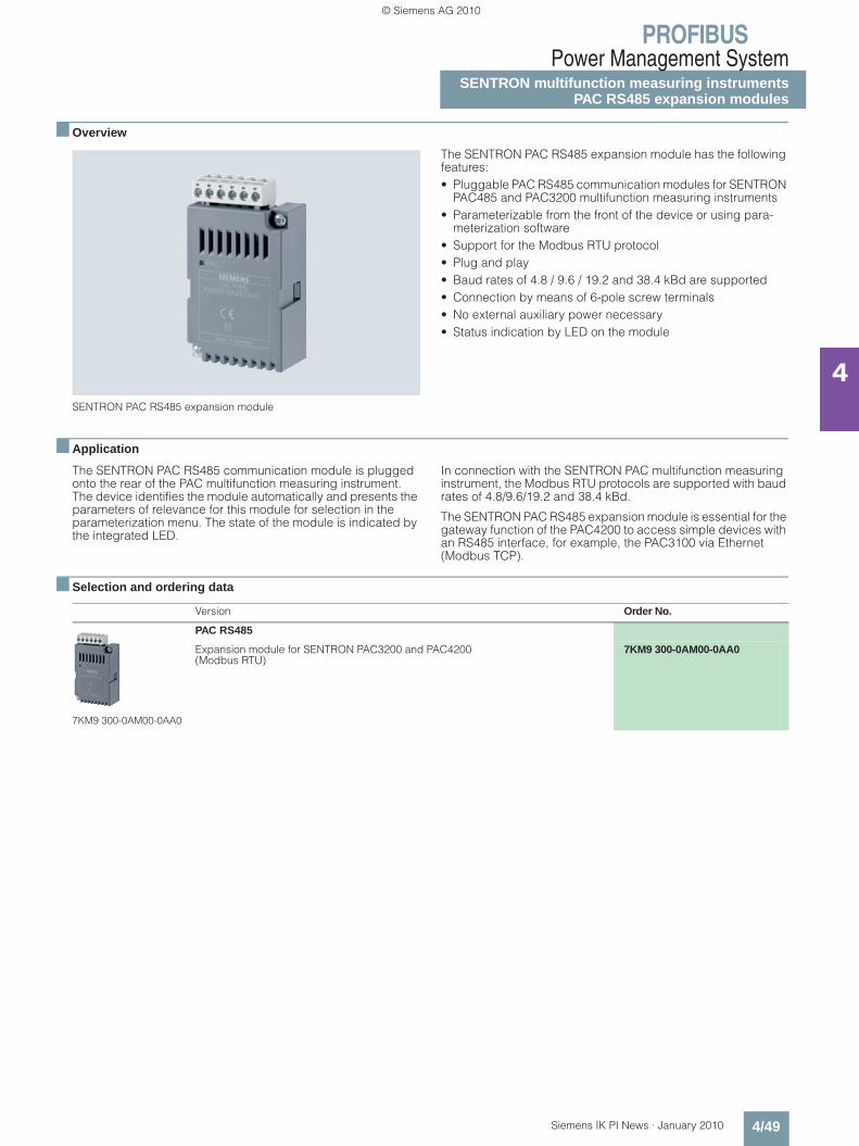
PROFIBUSPower Management System
SENTRON multifunction measuring instrumentsPAC RS485 expansion modules
4/49Siemens IK PI News · January 2010
4
■ Overview
SENTRON PAC RS485 expansion module
The SENTRON PAC RS485 expansion module has the following features:• Pluggable PAC RS485 communication modules for SENTRON
PAC485 and PAC3200 multifunction measuring instruments• Parameterizable from the front of the device or using para-
meterization software• Support for the Modbus RTU protocol• Plug and play• Baud rates of 4.8 / 9.6 / 19.2 and 38.4 kBd are supported• Connection by means of 6-pole screw terminals• No external auxiliary power necessary• Status indication by LED on the module
■ Application
The SENTRON PAC RS485 communication module is plugged onto the rear of the PAC multifunction measuring instrument. The device identifies the module automatically and presents the parameters of relevance for this module for selection in the parameterization menu. The state of the module is indicated by the integrated LED.
In connection with the SENTRON PAC multifunction measuring instrument, the Modbus RTU protocols are supported with baud rates of 4.8/9.6/19.2 and 38.4 kBd.
The SENTRON PAC RS485 expansion module is essential for the gateway function of the PAC4200 to access simple devices with an RS485 interface, for example, the PAC3100 via Ethernet (Modbus TCP).
■ Selection and ordering data
Version Order No.
7KM9 300-0AM00-0AA0
PAC RS485
Expansion module for SENTRON PAC3200 and PAC4200(Modbus RTU)
7KM9 300-0AM00-0AA0
Kap_04_en.fm Seite 49 Freitag, 29. Januar 2010 9:52 09
© Siemens AG 2010
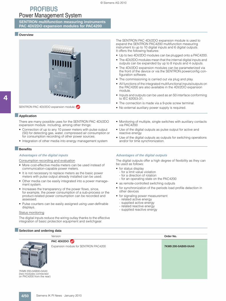
PROFIBUSPower Management SystemSENTRON multifunction measuring instrumentsPAC 4DI/2DO expansion modules for PAC4200
4/50 Siemens IK PI News · January 2010
4
■ Overview
SENTRON PAC 4DI/2DO expansion module
The SENTRON PAC 4DI/2DO expansion module is used to expand the SENTRON PAC4200 multifunction measuring instrument to up to 10 digital inputs and 6 digital outputs. It offers the following features:• Up to two 4DI/2DO modules can be plugged onto a PAC4200.• The 4DI/2DO modules mean that the internal digital inputs and
outputs can be expanded by up to 8 inputs and 4 outputs. • The 4DI/2DO expansion modules can be parameterized via
the front of the device or via the SENTRON powerconfig con-figuration software.
• The commissioning is carried out via plug and play.• All functions of the integrated multifunctional inputs/outputs on
the PAC4200 are also available in the 4DI/2DO expansion module.
• Inputs and outputs can be used as an S0 interface conforming to IEC 62053-31.
• The connection is made via a 9-pole screw terminal.• No external auxiliary power supply is required.
■ Application
There are many possible uses for the SENTRON PAC 4DI/2DO expansion module. including, among other things:• Connection of up to any 10 power meters with pulse output
(S0) for detecting gas, water, compressed air consumption or for consumption recording of other power sources.
• Integration of other media into energy management system
• Monitoring of multiple, single switches with auxiliary contacts via PAC4200
• Use of the digital outputs as pulse output for active and reactive energy
• Use of the digital outputs as outputs for switching operations and/or for time synchronization.
■ Benefits
Advantages of the digital inputs
Consumption recording and evaluation• More cost-effective media meters can be used instead of
communication-capable power meters.• It is not necessary to replace meters as the basic power
meters with pulse output already installed can be used.• Other media can be easily integrated into a power manage-
ment system.• Increases the transparency of the power flows, since,
for example, the power consumption of a sub-process or the product-related power consumption can be recorded and assessed.
• Pulse counters can be easily assigned using user-definable displays.
Status monitoring
The digital inputs reduce the wiring outlay thanks to the effective integration of basic protection equipment and switchgear.
Advantages of the digital outputs
The digital outputs offer a high degree of flexibility as they can be used as follows: • for status display
- for a limit value violation- for a direction of rotation- for an operating state on the PAC4200
• as remote-controlled switching outputs• for synchronization of the periods load profile detection in
other devices• for signaling power measurement
- related active energy- supplied active energy- related reactive energy- supplied reactive energy
■ Selection and ordering data
N
Version Order No.
7KM9 200-0AB00-0AA0(two modules connected on PAC4200 from the rear)
PAC 4DI/2DO
Expansion module for SENTRON PAC4200 7KM9 200-0AB00-0AA0N
Kap_04_en.fm Seite 50 Freitag, 29. Januar 2010 9:52 09
© Siemens AG 2010

PROFIBUSConfiguring, Visualizing and Controlling with SIMATIC
SIMATIC PCS 7 powerrate
4/51Siemens IK PI News · January 2010
4
■ Overview
SIMATIC PCS 7 powerrate
SIMATIC PCS 7 is an add-on to PCS 7 which throws light on power consumption from the infeed to the load. Power data are continuously collected, archived and processed further. With an exact knowledge of the consumption profile, it is possible to identify savings potential, optimize your power supply condi-tions and hence, lower your power costs. Monitoring the con-tractually agreed power limit helps on the one hand to prevent unnecessarily high power prices or penalties and on the other hand to make full use of the fixed power limit.
Batch-related consumption recording enables the exact record-ing and evaluation of power consumption per batch.
The integration of switches through digital inputs/outputs en-ables the monitoring or indication of switch status and, with suit-able authorization, remote switching. With integration through DPV1, selected measured values and signals of the SENTRON PAC3200 and SENTRON PAC4200 multifunction measuring in-struments can be indicated online.
Data recorded and archived by SIMATIC PCS 7 powerrate can be exported to Excel, and they can also be presented in different reports.
Full integration in PCS 7 enables the easy use of standard inter-faces or standard functionalities from PCS 7.
Components
SIMATIC PCS 7 powerrate is made up of the following compo-nents:• Modules for the acquisition and processing of power data• Faceplates for the presentation and processing of power data• Components for implementing load management (calculating
trends, monitoring limits, enabling/disabling loads)• Components for batch-related consumption recording• Components for the integration of measuring devices and
switches• Other components, for example, for time synchronization,
data buffering or data exchange with archives• Faceplates for presenting results and for entering values
(e.g. for configuration or from manual measured values)• Excel-based reports for allocating power data to cost centers,
for batch-related evaluations and for determining and present-ing the duration curve
• Exporting data to Excel
■ Benefits
• Identification of power-intensive consumer devices and pro-cesses in order to introduce measures for improving power efficiency
• Comparison of consumption profiles for greater efficiency of process design
• Optimizing the company according to energy parameters based on an assessment of consumption and costs
• Complying with the contractually agreed power limit, thus preventing higher power supply costs or penalty payments
• Integration of the SENTRON PAC3200 and SENTRON PAC4200 measuring devices, with a quick overview of selected measured values and signals
• Integration of switches, with an overview of switch status and switching possibilities
• Exact assignment and comparison of the consumption data of certain work processes through batch-related consumption recording
■ Application
SIMATIC PCS 7 powerrate is used in all areas in which PCS 7 is used and energy efficiency considerations play a major role. Full integration in PCS 7 means that there is no need for a special system environment. Predefined modules and symbols give you the assurance of building on tested and certified product components, with interfaces which enable customized expand-ability.
Kap_04_en.fm Seite 51 Freitag, 29. Januar 2010 9:52 09
© Siemens AG 2010

PROFIBUSConfiguring, Visualizing and Controlling with SIMATIC
SIMATIC PCS 7 powerrate
4/52 Siemens IK PI News · January 2010
4
■ Ordering data Order No.
SIMATIC PCS 7 V 6.1 SP1, V 6.1 SP2 and V 7.0 SP1
■ More information
You can find further general information on the Internet at: www.siemens.com/powermanagementsystem
You can find information on using SIMATIC PCS 7 powerrate at:support.automation.siemens.com/WW/view/en/38823708
SIMATIC PCS 7 powerrate V 3.0
• Trial licenseEngineering license limited to 30 days
3ZS2 785-1CC30-0YG7
• Engineering license and unlimited runtime license for operation on one PCS 7 OS (single workstation system orserver) and any number of automation systems (AS).When using additional PCS 7 OS devices, you need an engineering license for each PCS 7 OS.The PAC3200 function block libraries for SIMATIC PCS 7(order no. 3ZS2 781-1CC10-0YG0) and 3WL/3VL for SIMATIC PCS 7 (order no. 3ZS2 782-1CC10-0YG0) are included at no charge with the license.
3ZS2 785-1CC30-0YG0
Upgrade from SIMATIC PCS 7 powerrate V 2.0 to V 3.0
• Engineering license and unlimited runtime license for operation on one PCS 7 OS (single workstation system or server) and any number of automation systems (AS).When using additional PCS 7 OS devices, you need an engineering license for each PCS 7 OS.The PAC3200 function block libraries for SIMATIC PCS 7 (order no. 3ZS2 781-1CC10-0YG0) and 3WL/3VL for SIMATIC PCS 7 (order no. 3ZS2 782-1CC10-0YG0) are included at no charge with the license.
3ZS2 785-1CC30-0YE0
Kap_04_en.fm Seite 52 Freitag, 29. Januar 2010 9:52 09
© Siemens AG 2010
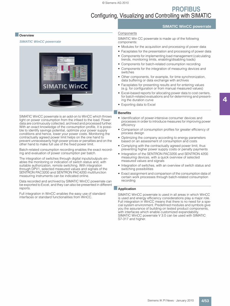
PROFIBUSConfiguring, Visualizing and Controlling with SIMATIC
SIMATIC WinCC powerrate
4/53Siemens IK PI News · January 2010
4
■ Overview
SIMATIC WinCC powerrate
SIMATIC WinCC powerrate is an add-on to WinCC which throws light on power consumption from the infeed to the load. Power data are continuously collected, archived and processed further. With an exact knowledge of the consumption profile, it is possi-ble to identify savings potential, optimize your power supply conditions and hence, lower your power costs. Monitoring the contractually agreed power limit helps on the one hand to prevent unnecessarily high power prices or penalties and on the other hand to make full use of the fixed power limit.
Batch-related consumption recording enables the exact record-ing and evaluation of power consumption per batch.
The integration of switches through digital inputs/outputs en-ables the monitoring or indication of switch status and, with suitable authorization, remote switching. With integration through DPV1, selected measured values and signals of the SENTRON PAC3200 and SENTRON PAC4200 multifunction measuring instruments can be indicated online.
Data recorded and archived by SIMATIC WinCC powerrate can be exported to Excel, and they can also be presented in different reports.
Full integration in WinCC enables the easy use of standard interfaces or standard functionalities from WinCC.
Components
SIMATIC Win CC powerrate is made up of the following components:• Modules for the acquisition and processing of power data• Faceplates for the presentation and processing of power data• Components for implementing load management (calculating
trends, monitoring limits, enabling/disabling loads) • Components for batch-related consumption recording• Components for the integration of measuring devices and
switches• Other components, for example, for time synchronization,
data buffering or data exchange with archives• Faceplates for presenting results and for entering values
(e.g. for configuration or from manual measured values)• Excel-based reports for allocating power data to cost centers,
for batch-related evaluations and for determining and present-ing the duration curve
• Exporting data to Excel
■ Benefits
• Identification of power-intensive consumer devices and processes in order to introduce measures for improving power efficiency
• Comparison of consumption profiles for greater efficiency of process design
• Optimizing the company according to energy parameters based on an assessment of consumption and costs
• Complying with the contractually agreed power limit, thus preventing higher power supply costs or penalty payments
• Integration of the SENTRON PAC3200 and SENTRON 4200 measuring devices, with a quick overview of selected measured values and signals
• Integration of switches, with an overview of switch status and switching possibilities
• Exact assignment and comparison of the consumption data of certain work processes through batch-related consumption recording
■ Application
SIMATIC WinCC powerrate is used in all areas in which WinCC is used and energy efficiency considerations play a major role. Full integration in WinCC means that there is no need for a spe-cial system environment. Predefined modules and symbols give you the assurance of building on tested product components, with interfaces which enable customized expandability. SIMATIC WinCC powerrate V 3.0 can be used with SIMATIC S7-317 and higher.
Kap_04_en.fm Seite 53 Freitag, 29. Januar 2010 9:52 09
© Siemens AG 2010

PROFIBUSConfiguring, Visualizing and Controlling with SIMATIC
SIMATIC WinCC powerrate
4/54 Siemens IK PI News · January 2010
4
■ Ordering data Order No.
SIMATIC WinCC V 6.2 SP2 and V 7.0
■ More information
You can find further general information on the Internet at: www.siemens.com/powermanagementsystem
You can find information on using SIMATIC PCS 7 powerrate at:support.automation.siemens.com/WW/view/en/38823708
SIMATIC WinCC powerrate V 3.0
• Trial licenseEngineering license limited to 30 days
3ZS2 795-1CC30-0YG7
• Engineering licenseand unlimited runtime license for operation on one WinCC OS (single workstation system or server) and any number of automation systems (AS).When using additional WinCC OS devices, you need an engineering license for each WinCC OS.The PAC3200 function block libraries for SIMATIC WinCC (order no. 3ZS2 791-1CC10-0YG0) are included at no charge with the license.
3ZS2 795-1CC30-0YG0
Upgrade from SIMATIC WinCC powerrate V 2.0 to V 3.0
• Engineering licenseand unlimited runtime license for operation on one WinCC OS (single workstation system or server) and any number of automation systems (AS).When using additional WinCC OS devices, you need an engineering license for each WinCC OS.The PAC3200 function block libraries for SIMATIC WinCC(order no. 3ZS2 791-1CC10-0YG0) are included at no charge with the license.
3ZS2 795-1CC30-0YE0
Kap_04_en.fm Seite 54 Mittwoch, 3. Februar 2010 8:49 08
© Siemens AG 2010

PROFIBUSConfiguring, Visualizing and Controlling with SIMATIC
SIMATIC PCS 7 Library PAC3200
4/55Siemens IK PI News · January 2010
4
■ Overview
SIMATIC PCS 7 Library PAC3200
The PCS 7 function block library – SIMATIC PCS 7 Library PAC3200 – for the SENTRON PAC3200 multifunction measuring instrument enables the seamless integration of the multifunction instrument in the PCS 7 process world.
It comprises one driver block, one diagnostics block and the faceplates. The blocks in the SIMATIC S7 supply energy data to the faceplates in the user interface of the process control sys-tem, generate signals and guarantee connection to the mainte-nance system of PCS 7.
Faceplates
Faceplates serve as a user interface for operating and monitor-ing and enable technologically important values and functions of the SENTRON PAC3200 to be displayed and performed as a PCS 7 object.
Between the faceplates and the modules as well as between the modules and the SENTRON PAC3200 there exist on the system side bidirectional communication connections not only for dis-playing values in the faceplates, but also for forwarding input data to the device.
This makes the SENTRON PAC3200 power monitoring device an integral component of PCS 7.
The operating systems supported are the same as those for the SIMATIC PCS 7.
■ Benefits
• Full integration of SENTRON PAC3200 in the PCS 7 process control system through PROFIBUS DPV1 using a certifiedPCS 7 add-on module
• Reading out and displaying device data• Inputting limit values for monitoring through the driver block• Resetting values on the device (min/max values)
■ Application
SIMATIC PCS 7 Library PAC3200 is used in all areas in which PCS 7 is used. Full integration in PCS 7 means that there is no need for a special system environment. Predefined modules and symbols give you the assurance of building on tested and certified product components.
■ Ordering data Order No.
SIMATIC PCS 7 V 6.1 SP1, PCS 7 V 7.0 SP1 and PCS 7 V 7.1
SIMATIC PCS 7 Library PAC3200
• Engineering licensefor operation on one PCS 7 OS (single workstation system or server) and an automation system (AS). When using additional PCS 7 OS devices, you need an engineering license for each PCS 7 OS.
3ZS2 781-1CC10-0YG0
• Runtime license for operation on an additional AS
3ZS2 781-1CC10-6YH0
Kap_04_en.fm Seite 55 Mittwoch, 3. Februar 2010 9:00 09
© Siemens AG 2010

PROFIBUSConfiguring, Visualizing and Controlling with SIMATIC
3WL/3VL function block library for SIMATIC PCS 7
4/56 Siemens IK PI News · January 2010
4
■ Overview
3WL/3VL function block library for SIMATIC PCS 7
The 3WL/3VL PCS 7 function block library for SENTRON circuit breaker allows for the simple and quick integration of the SENTRON circuit breaker into the PCS 7 process world.
It comprises one driver block, one diagnostics block and the faceplates. The blocks in the SIMATIC S7 supply current, power and energy data to the faceplates in the user interface of the process control system, generate signals and guarantee con-nection to the maintenance system of PCS 7.
Faceplates
Faceplates serve as a user interface for operating and monitor-ing and enable the SENTRON circuit breaker to be displayed and performed simply as a PCS 7 object.
The 3WL/3VL function block library for SIMATIC PCS 7 provides for continual plant transparency. Critical plant states are recog-nized quickly and costs owing to outages avoided. System avail-ability is permanently increased
This transforms the SENTRON circuit breaker into an integral component of PCS 7.
The operating systems supported are the same as those for the SIMATIC PCS 7.
■ Benefits
• Full integration of SENTRON circuit breaker in the PCS 7 process control system through PROFIBUS DPV1 using a certified PCS 7 add-on module
• Remote switching and monitoring• Reading out of maintenance information• Automatic information in case of overload, short-circuit and
faults• Reading out and displaying device data• Limit monitoring through the driver block• Resetting values on the device (min/max values)
■ Application
The 3WL/3VL function block for SIMATIC PCS 7 is used in all areas in which PCS 7 is used. Full integration in PCS 7 means that there is no need for a special system environment. Predefined modules and symbols give you the assurance of building on tested and certified product components.
■ Ordering data Order No.
SIMATIC PCS 7 V 6.1 SP1 and PCS 7 V 7.0 SP1
3WL/3VL function block library for SIMATIC PCS 7
• Engineering licensefor operation on one PCS 7 OS (single workstation system or server) and an automation system (AS).When using additional PCS 7 OS devices, you need an engineering license for each PCS 7 OS.
3ZS2 782-1CC10-0YG0
• Runtime licensefor operation on an additional AS
3ZS2 782-1CC10-6YH0
Kap_04_en.fm Seite 56 Mittwoch, 3. Februar 2010 8:52 08
© Siemens AG 2010

PROFIBUSConfiguring, Visualizing and Controlling with SIMATIC
PAC3200 function block libraryfor SIMATIC WinCC
4/57Siemens IK PI News · January 2010
4
■ Overview
SENTRON PAC3200 function block library for SIMATIC WinCC
The SENTRON PAC3200 function block library for SIMATIC WinCC enables the seamless integration of the SENTRON PAC3200 multifunction measuring instrument in WinCC.
It comprises one driver block, one diagnostics block and the faceplates. The blocks in the SIMATIC S7 supply energy data to the faceplates in the user interface of WinCC, generate signals and guarantee connection to the maintenance system of WinCC.
Faceplates
Faceplates serve as a user interface for operating and monitor-ing and enable technologically important values and functions of the SENTRON PAC3200 to be displayed and performed in WinCC.
Between the faceplates and the modules as well as between the modules and the SENTRON PAC3200 there exist on the system side bidirectional communication connections not only for dis-playing values in the faceplates, but also for forwarding input data to the device.
This makes the SENTRON PAC3200 multifunction measuring instrument an integral component of WinCC.
System requirements
The SENTRON PAC3200 function block library for SIMATIC WinCC is released for • WinCC V 6.2 SP2• WinCC V 7.0 and• WinCC V 7.0 SP1
WinCC options AS-OS Engineering and Basic Process Control must be installed. The function block library is available for both S7-300 and S7-400. At least one S7 CPU317-2DP is required for use in the S7-300 area. At least one S7 CPU414-2 is required for use in the S7-400 area.
Supported operating systems are the same as for SIMATIC WinCC.
■ Benefits
• Full integration of the SENTRON PAC3200 in SIMATIC WinCC through PROFIBUS DPV1 The function block library is a certified WinCC add-on module
• Reading out and displaying device data• Inputting limit values for monitoring through the driver block• Resetting values on the device (min/max values)
■ Application
The SENTRON PAC3200 function block library for SIMATIC WinCC is used in all areas in which WinCC is used. Full integra-tion in WinCC means that there is no need for a special system environment. Predefined modules and symbols give you the assurance of building on tested and certified product compo-nents.
■ Ordering data Order No.
SIMATIC WinCC V 6.2 SP2, WinCC V 7.0 and WinCC V 7.0 SP1
SENTRON PAC3200 function block library for SIMATIC WinCC
• Engineering licensefor operation on one WinCC OS (single workstation system or server) and an automation system (AS).When using additional WinCC OS devices, you need an engineering license for each WinCC OS.
3ZS2 791-1CC10-0YG0
• Runtime licensefor operation on an additional AS
3ZS2 791-1CC10-6YH0
Kap_04_en.fm Seite 57 Freitag, 29. Januar 2010 9:52 09
© Siemens AG 2010

PROFIBUSConfiguring, Visualizing and Controlling with SENTRON
Switch ES Power
4/58 Siemens IK PI News · January 2010
4
■ Overview
Switch ES Power
Adjustment of parameter set A with Switch ES Power
Switch ES Power is the shared software platform for communica-tion-capable SENTRON circuit breakers. This has the advantage that all device-specific setting options are identical in terms of appearance and handling.
Switch ES Power can be used to configure, document, operate and monitor the SENTRON 3WL and SENTRON 3VL circuit breakers through PROFIBUS DP.
More information can be found on the Internet at:www.siemens.com/sentron
■ Benefits
• Parameterization, documentation, operation and monitoring in one software
• Documentation of measured values and settings• Clear representation of all available parameters• All the available status information and measured values are
clearly displayed in dialog boxes• Software for SENTRON 3WL and SENTRON 3VL• Easy connection build-up through acyclic PROFIBUS DPV1
data traffic• Identical storage format for parameters with the Breaker Data
Adapter (BDA)• Easy-to-operate Windows interface• No programming knowhow is required for operation
Object manager of Switch ES Power• Uniform data management for circuit breaker parameters• Automatic parameterization if components are replaced
■ Ordering data Order No.
Switch ES Power 3ZS2 311-0CC10-0YA0
Calibration, documentation, operation and monitoring of SENTRON 3WL/3VL circuit breakers through PROFIBUS DP; runs under Windows 95/98/NT/2000/XP Professional, including online help, the language can be switched between German and English; including Object Manager (OM) for Switch ES Power for integration in STEP7
System requirements: PROFIBUS card: CP 5512, CP 5611, CP 5613 or CP 5614and MPI interface on PG7xx andits driver software, see interactive Catalog CA01, CD-ROM drive
System requirementsfor OM Switch ES Power: SIMATIC: S7, M7, C7, PCS 7STEP 7: version 5.2 or higherCD-ROM drive
Kap_04_en.fm Seite 58 Freitag, 29. Januar 2010 9:52 09
© Siemens AG 2010

PROFIBUSSIMATIC FS600 laser scanner
PROFIsafe laser scanner
4/59Siemens IK PI News · January 2010
4
■ Overview
The laser scanner is an optical distance sensor for flexible monitoring of hazardous areas in horizontal applications, for ac-cess control in vertical applications, and for motion monitoring.
They provide perfect all-round protection up to Category 3 according to EN 954-1, SIL 2 according to IEC 61508, and PL d according to ISO 13849-1.
SIMATIC FS600 laser scanners work in an operating field of 190° and over a distance of up to 6.25 m. In this range the laser scanner reliably senses every object and every person.
And it works so simply: The distance sensor emits light pulses at regular intervals. If they hit an obstruction, the sensor receives the reflected light and evaluates it. If this is evaluated as the pre-defined area to be protected, a Stop function is triggered.
With up to 8 programmable protective fields that can be selected during operation, our laser scanners can be optimally adapted to any application – on machines, production robots, conveyor systems, or vehicles.
Different variants support optimal integration in the automation system: Whether conventionally in the safety circuit, over PROFIBUS with PROFIsafe or over AS-Interface with ASIsafe.
■ Integration
��
��
����
��
��
�� ��
��������
Terminal Description Item Connectable accessories Order No.
X1 M12 connector for connecting a restart button (optional)
1 M12 connector with terminal housing, 5-pin 3RX8 000-0CD55
X2 M12 socket for PROFIBUS output cable 2 Terminating resistor for PROFIBUS DP 6GK1 905-0EC00
3 PROFIBUS M12 connecting cable, with plug and socket, 2-pin
6XV1 830-3DE50( 0.5 m) 6XV1 830-3DH15 (1.5 m)6XV1 830-3DH30 (3 m) 6XV1 830-3DH50 (5 m) 6XV1 830-3DN10 (10 m) 6XV1 830-3DN15 (15 m)
4 PROFIBUS M12 connecting plug with male insert
6GK1 905-0EA00
X3 M12 plug for PROFIBUS input cable 3 PROFIBUS M12 connecting cable, with plug and socket, 2-pin
6XV1 830-3DE50 (0.5 m) 6XV1 830-3DH15 (1.5 m) 6XV1 830-3DH30 (3 m) 6XV1 830-3DH50 (5 m) 6XV1 830-3DN10 (10 m) 6XV1 830-3DN15 (15 m)
5 PROFIBUS M12 connecting plug with female insert
6GK1 905-0EB00
X4 M12 plug for 24 V DC power supply 6 M12 cable socket with terminal housing, 5-pin 3RX8 000-0CB55
X5 Optical PC interface 7 PC connecting cable for laser scanner with optical interface, 9-pin
3RG78 38-1DC
Kap_04_en.fm Seite 59 Freitag, 29. Januar 2010 9:52 09
© Siemens AG 2010

PROFIBUSSIMATIC FS600 laser scanner
PROFIsafe laser scanner
4/60 Siemens IK PI News · January 2010
4
■ Technical specifications
Type PROFIsafe laser scanner
Protective field
Protective field 2.15 m, 4 m, 6.25 m
Degree of remission min. 1.8 %
Resolutions Resolutions: 30, 40, 50, 70, 150 mm
Response time
• 2-fold evaluation (2 scans) 80 ms (laser scanner only, without PROFIBUS system times)
• Adjustable up to 16 scans 640 ms (laser scanner only, without PROFIBUS system times)
Number 4 (selectable via PROFIBUS)
Safety category acc. to IEC 61508 SIL 2
Output PROFIBUS (PROFIsafe profile)
Start-up Start-up test and start-up disable can be set separately
Warm restart 160 ms to 10 s (settable or manually)
Protective field additional distance
• with dust suppression deactivated
83 mm
• with dust suppression activated
- for protective fields < 3.5 mm 83 mm
- for protective fields > 3.5 mm 100 mm
• Additional distance for retro-reflectors or strongly reflective surfaces (such as certain metals or ceramics in the scan plane)- over 1.2 m behind the protective
field line0 mm
- in the protective field or up to 1.2 m behind the protective field line
110 mm
Warning zone
Detection zone 0 ... 15 m
Degree of remission min. 20%
Object size 150 × 150 mm
Response time
• 2-fold evaluation (2 scans) 80 ms (laser scanner only, without PROFIBUS system times)
• Adjustable up to 16 scans 640 ms (laser scanner only, without PROFIBUS system times)
Number of warning zones 4 / 8 (selectable via PROFIBUS)
Output PROFIBUS
Type PROFIsafe laser scanner
Contour measurement
Detection zone 0 ... 50 m
Degree of remission min. 20%
Output RS232 serial interface via infrared interface
Radial resolution 5 mm
Lateral resolution 0.36 °
Supply voltage
• via external supply 24 V DC (+20 % / -30 %)
• Note The power supply unit for the external power supply must feature safe isolation from the supply according to IEC 60742 and bridge temporary power failures of up to 20 ms.
Overcurrent protection Fuse 1.25 A, slow acting
Current consumption typ. 350 mA
Inputs
Restart/Reset Connection of a command device for operating mode "With restart inhibit" and/or device reset, dynamically monitored
Signal definition
• High (logic 1) 16 ... 30 V
• Low (logic 0) < 3 V
Control cable
• Length max. 50 m (with 0.5 mm2 conductor cross-section, shielded)
Field pair switchover Field pair switchover over PROFIBUS (PROFIsafe profile)
RS232 interfaces by means of infrared interface
For device parameterization and field function
Optical system
Range of angle 190 °
Angle resolution 0.36 °
Lateral tolerance
• without mounting system (with ref-erence to rear of enclosure)
± 0.18 °
• with mounting system (with refer-ence to the mounting surface)
± 0.22 °
Scan rate 25 scans/s or 40 ms/scan
Laser protection class
- according to standard EN 60825-1, Class 1(safe for eyes)
Wave length 905 nm
Beam divergence 2 mrad
Time basis 100 s
Kap_04_en.fm Seite 60 Freitag, 29. Januar 2010 9:52 09
© Siemens AG 2010
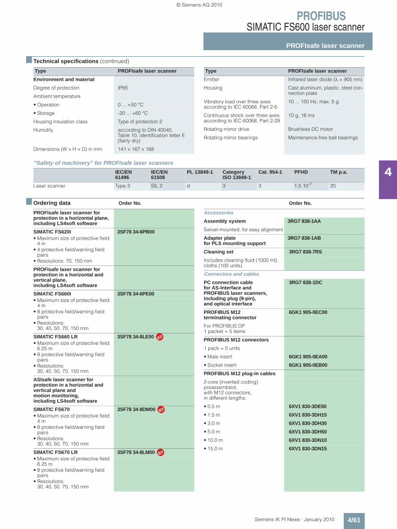
PROFIBUSSIMATIC FS600 laser scanner
PROFIsafe laser scanner
4/61Siemens IK PI News · January 2010
4
■ Technical specifications (continued)
"Safety of machinery" for PROFIsafe laser scanners
■ Ordering data Order No. Order No.
Type PROFIsafe laser scanner
Environment and material
Degree of protection IP65
Ambient temperature
• Operation 0 ... +50 °C
• Storage -20 ... +60 °C
Housing insulation class Type of protection 2
Humidity according to DIN 40040, Table 10, identification letter E (fairly dry)
Dimensions (W × H × D) in mm 141 × 167 × 168
Type PROFIsafe laser scanner
Emitter Infrared laser diode (λ = 905 nm)
Housing Cast aluminum, plastic, steel con-nection plate
Vibratory load over three axes according to IEC 60068, Part 2-6
10 ... 150 Hz, max. 5 g
Continuous shock over three axes according to IEC 60068, Part 2-29
10 g, 16 ms
Rotating mirror drive Brushless DC motor
Rotating mirror bearings Maintenance-free ball bearings
IEC/EN 61496
IEC/EN 61508
PL 13849-1 Category ISO 13849-1
Cat. 954-1 PFHD TM p.a.
Laser scanner Type 3 SIL 2 d 3 3 1.5 10-7 20
PROFIsafe laser scanner for protection in a horizontal plane, including LS4soft software
SIMATIC FS620I 3SF78 34-6PB00• Maximum size of protective field:
4 m• 4 protective field/warning field
pairs• Resolutions: 70, 150 mm
PROFIsafe laser scanner for protection in a horizontal and vertical plane,including LS4soft software
SIMATIC FS660I 3SF78 34-6PE00• Maximum size of protective field:
4 m• 8 protective field/warning field
pairs• Resolutions:
30, 40, 50, 70, 150 mm
SIMATIC FS660 LR 3SF78 34-8LE00 • Maximum size of protective field:
6.25 m• 8 protective field/warning field
pairs• Resolutions:
30, 40, 50, 70, 150 mm
ASIsafe laser scanner for protection in a horizontal and vertical plane and motion monitoring, including LS4soft software
SIMATIC FS670 3SF78 34-8DM00 • Maximum size of protective field:
4 m• 8 protective field/warning field
pairs• Resolutions:
30, 40, 50, 70, 150 mm
SIMATIC FS670 LR 3SF78 34-8LM00 • Maximum size of protective field:
6.25 m• 8 protective field/warning field
pairs• Resolutions:
30, 40, 50, 70, 150 mm
N
N
N
Accessories
Assembly system 3RG7 838-1AA
Swivel-mounted, for easy alignment
Adapter plate for PLS mounting support
3RG7 838-1AB
Cleaning set 3RG7 838-7RS
Includes cleaning fluid (1000 ml), cloths (100 units)
Connectors and cables
PC connection cable for AS-Interface and PROFIBUS laser scanners,including plug (9-pin), and optical interface
3RG7 838-1DC
PROFIBUS M12 terminating connector
6GK1 905-0EC00
For PROFIBUS DP 1 packet = 5 items
PROFIBUS M12 connectors
1 pack = 5 units
• Male insert 6GK1 905-0EA00
• Socket insert 6GK1 905-0EB00
PROFIBUS M12 plug-in cables
2-core (inverted coding) preassembled, with M12 connectors, in different lengths:
• 0.5 m 6XV1 830-3DE50
• 1.5 m 6XV1 830-3DH15
• 3.0 m 6XV1 830-3DH30
• 5.0 m 6XV1 830-3DH50
• 10.0 m 6XV1 830-3DN10
• 15.0 m 6XV1 830-3DN15
Kap_04_en.fm Seite 61 Freitag, 29. Januar 2010 9:52 09
© Siemens AG 2010
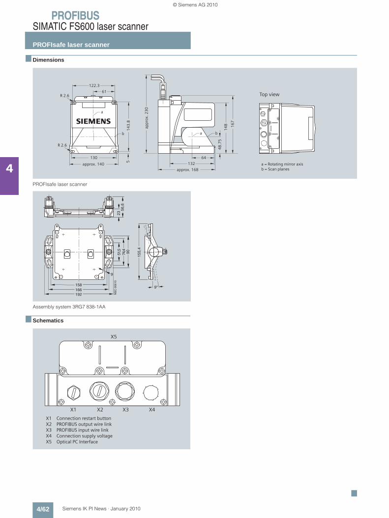
PROFIBUSSIMATIC FS600 laser scanner
PROFIsafe laser scanner
4/62 Siemens IK PI News · January 2010
4
■ Dimensions
PROFIsafe laser scanner
Assembly system 3RG7 838-1AA
■ Schematics
■
61
approx. 140
130
R 2.6
5s
R 2.6
122.3
14
3.8
b
a
Top view
a = Rotating mirror axisb = Scan planes
appr
ox. 2
30
approx. 168
48
.75
64
132
14
8 16
7
a b
����
����
���
� �
��������
����
�����
����
X5
X1 X2 X3 X4
X1 Connection restart buttonX2 PROFIBUS output wire linkX3 PROFIBUS input wire linkX4 Connection supply voltageX5 Optical PC Interface
Kap_04_en.fm Seite 62 Freitag, 29. Januar 2010 9:52 09
© Siemens AG 2010