industrial duty commercial door operator duty commercial door operator l 3ogic not for residential...
TRANSCRIPT

This Operator Features the Enhanced
Radio Receiver Built on Board
O W N E R ’ S M A N U A L
GHINDUSTRIAL DUTY COMMERCIAL DOOR OPERATOR
ogicL 3
NOT FOR RESIDENTIAL USE
AL
ER
T S Y ST
EM
MA
INTENAN
CE
PATENT PENDING
The Maintenance Alert System™ allows the installer to set an internal Maintenance Cycle Counter. The Logic 3 operator incorporates a self-diagnostic feature built into the (MAS) Maintenance Alert System LED. An LED on the 3-button station will signal when the set number of cycles/months is reached or when the operator requires immediate service.
Serial # Box
Installation Date
2 Y E A R W A R R A N T Y315MHz
Visit www.LiftMaster.com to locate a professional installing dealer in your area.
INTENDED FOR PROFESSIONAL INSTALLATION ONLY
A SAFETY DEVICE IS HIGHLY RECOMMENDED

2
When you see these Safety Symbols and Signal Words on the following pages, they will alert you to the possibility of serious injury or death if you do not comply with the warnings that accompany them. The hazard may come from something mechanical or from electric shock. Read the warnings carefully.When you see this Signal Word on the following pages, it will alert you to the possibility of damage to your door and/or the door operator if you do not comply with the cautionary statements that accompany it. Read them carefully.
Mechanical
Electrical
ATTENTION
AVERTISSEMENT AVERTISSEMENT
AVERTISSEMENT
WARNING WARNING
CAUTION
WARNING
WARNING
PRECAUCIÓN ADVERTENCIA
ADVERTENCIA ADVERTENCIA
ATTENTION
AVERTISSEMENT AVERTISSEMENT
AVERTISSEMENT
WARNING
CAUTION
WARNING WARNING
WARNING
PRECAUCIÓN ADVERTENCIA
ADVERTENCIA ADVERTENCIA
ATTENTION
AVERTISSEMENT AVERTISSEMENT
AVERTISSEMENT
WARNING
CAUTION CAUTION
WARNING
WARNING
PRECAUCIÓN ADVERTENCIA
ADVERTENCIA ADVERTENCIA
SPECIFICATIONSCarton Inventory . . . . . . . . . . . . . . . . . . . . . . . . . . . . . . . . . . . . . .3Operator Dimensions . . . . . . . . . . . . . . . . . . . . . . . . . . . . . . . . . .3Operator Specifications. . . . . . . . . . . . . . . . . . . . . . . . . . . . . . . . .4
PREPARATIONHand Chain Right/Left Conversion . . . . . . . . . . . . . . . . . . . . . . . .5Disconnect Lever Right/Left Conversion. . . . . . . . . . . . . . . . . . . .5Horizontal Mounting Conversion . . . . . . . . . . . . . . . . . . . . . . . . .5
INSTALLATIONMount the Operator . . . . . . . . . . . . . . . . . . . . . . . . . . . . . . . . . . .6Manual Operation . . . . . . . . . . . . . . . . . . . . . . . . . . . . . . . . . . . . .7Entrapment Protection Accessories . . . . . . . . . . . . . . . . . . . . . . .8
ADJUSTMENTLimit Switch Adjustment. . . . . . . . . . . . . . . . . . . . . . . . . . . . . . . .8Adjust Torque Limiter Clutch . . . . . . . . . . . . . . . . . . . . . . . . . . . .9Brake Adjustment . . . . . . . . . . . . . . . . . . . . . . . . . . . . . . . . . . . . .9
POWER & GROUND WIRINGSafety Warnings . . . . . . . . . . . . . . . . . . . . . . . . . . . . . . . . . . . . .10Power Wiring Connections . . . . . . . . . . . . . . . . . . . . . . . . . . . . .10Ground Wiring Connections . . . . . . . . . . . . . . . . . . . . . . . . . . . .10
CONTROL STATION WIRING & INSTALLATIONControl Wiring Connections . . . . . . . . . . . . . . . . . . . . . . . . . . . .11Mounting Instructions . . . . . . . . . . . . . . . . . . . . . . . . . . . . . . . .11External Radio Wiring Connections . . . . . . . . . . . . . . . . . . . . . .11
DIAGRAMSStandard Power & Control Connection Diagrams. . . . . . . . . . . .121 Phase Wiring Diagram. . . . . . . . . . . . . . . . . . . . . . . . . . . . . . .133 Phase Wiring Diagram. . . . . . . . . . . . . . . . . . . . . . . . . . . . . . .14Logic Board . . . . . . . . . . . . . . . . . . . . . . . . . . . . . . . . . . . . . . . .15
PROGRAMMINGLogic Control Pushbuttons . . . . . . . . . . . . . . . . . . . . . . . . . . . . .16Determine and Set Wiring Type . . . . . . . . . . . . . . . . . . . . . . . . .16Failsafe Wiring Types . . . . . . . . . . . . . . . . . . . . . . . . . . . . . . . . .17Self-Monitoring Safety Device Options . . . . . . . . . . . . . . . . . . . .17Programming Remotes. . . . . . . . . . . . . . . . . . . . . . . . . . . . . 18-19Maintenance Alert System (MAS). . . . . . . . . . . . . . . . . . . . . . . .20Mid Stop . . . . . . . . . . . . . . . . . . . . . . . . . . . . . . . . . . . . . . . . . . .21Timer to Close . . . . . . . . . . . . . . . . . . . . . . . . . . . . . . . . . . . 21-22Car Dealer Mode . . . . . . . . . . . . . . . . . . . . . . . . . . . . . . . . . . . . .22
AUTOMATICALLY LEARNED PROGRAMMINGAuxiliary Reversal System/RPM Sensor . . . . . . . . . . . . . . . . . . .23Maximum Run Timer (MRT). . . . . . . . . . . . . . . . . . . . . . . . . . . .23
OPTIONAL PROGRAMMINGRed/Green Warning Light Card. . . . . . . . . . . . . . . . . . . . . . . . . .24Resetting Factory Defaults - Clearing Memory . . . . . . . . . . . . . .24
MAINTENANCEMaintenance Schedule . . . . . . . . . . . . . . . . . . . . . . . . . . . . . . . .25Life of Operator Feature . . . . . . . . . . . . . . . . . . . . . . . . . . . . . . .25How to Order Repair Parts . . . . . . . . . . . . . . . . . . . . . . . . . . . . .25
TROUBLESHOOTINGDiagnostic Chart . . . . . . . . . . . . . . . . . . . . . . . . . . . . . . . . . . . . .26Troubleshooting Guide . . . . . . . . . . . . . . . . . . . . . . . . . . . . . . . .27Troubleshooting Error Codes . . . . . . . . . . . . . . . . . . . . . . . . . . .28Troubleshooting Radio Functionality . . . . . . . . . . . . . . . . . . . . .29
REPAIR PARTSElectrical Box . . . . . . . . . . . . . . . . . . . . . . . . . . . . . . . . . . . . 30-31Repair Parts Kits . . . . . . . . . . . . . . . . . . . . . . . . . . . . . . . . . 32-33Operator Notes . . . . . . . . . . . . . . . . . . . . . . . . . . . . . . . . . . 34-35Control Connection Diagram. . . . . . . . . . . . . . . . . . . . . . . . . . . .36
IMPORTANT NOTES:• BEFORE attempting to install, operate or maintain the operator,
you must read and fully understand this manual and follow all safety instructions.
• DO NOT attempt installation, repair or service of your commercial door and gate operator unless you are an Authorized Service Technician.
T A B L E O F C O N T E N T S

3
Before beginning your installation check that all components were provided.
14.00"
Hand Chain Wheel
See
Note #1See Note #2
A
X
BY
C
D
Y
See Note #3
NOTES:1) Output Shaft with: 1" x 1/4" Key for 1/2 thru 1 HP operators, 1-3/16" x 5/16" Key for 1-1/2 & 2 HP operators
and 1-1/4" x 1/4" Key for 3 HP operators.2) Mounting Centers: X = 4-3/4"; Y = 5-1/2" for 1/2 thru 2HP operators
X = 7-17/32"; Y = 9-1/16" for 3HP operators3) Hand Chain Wheel extends 1-5/8" beyond operator in vertical mounting position as shown.
WEIGHTS AND DIMENSIONSHANGING WEIGHT: 80-110 LBS.
DESCRIPTION POWERHEAD ASSEMBLY OWNER’S MANUAL AND CAUTION LABELS HARDWARE BOX (INCLUDES FASTENERS, DISCONNECT AND CHAIN HOIST WALL BRACKET) 3-BUTTON CONTROL STATION WITH LED HOIST HAND CHAIN DOOR SPROCKET DOOR/OPERATOR DRIVE CHAIN
HP PHASEDIMENSIONS
A B C D
1/2 1 11-1/2 25-3/4 14.13 3
3/4 1 12-1/2 26-3/4 14.13 3
1 1 12-3/4 27 14.13 3
1-1/2 1 12-3/4 27 15.13 3-1/2
1/2 3 11 25-1/4 14.13 3
3/4 3 11 25-1/4 14.13 3
1 3 12 26-1/4 14.13 3
1-1/2 3 12-1/2 26-3/4 15.13 3-1/2
2 3 12-3/4 27 15.13 3-1/2
3 3 13-1/4 28-5/8 17.13 3
O P E R A T O R D I M E N S I O N S
C A R T O N I N V E N T O R Y
4
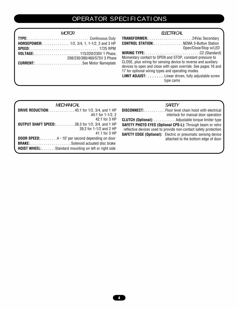
SAFETYDISCONNECT: . . . . . . . . . . . Floor level chain hoist with electrical
interlock for manual door operationCLUTCH (Optional): . . . . . . . . . . . Adjustable torque limiter typeSAFETY PHOTO EYES (Optional CPS-L): Through beam or retroreflective devices used to provide non-contact safety protection
SAFETY EDGE (Optional): Electric or pneumatic sensing device attached to the bottom edge of door
MOTORTYPE: . . . . . . . . . . . . . . . . . . . . . . . . . . . . . . . .Continuous DutyHORSEPOWER: . . . . . . . . . . . . . 1/2, 3/4, 1, 1-1/2, 2 and 3 HP SPEED: . . . . . . . . . . . . . . . . . . . . . . . . . . . . . . . . . . . 1725 RPMVOLTAGE: . . . . . . . . . . . . . . . . . . . . . . . 115/220/230V 1 Phase,
208/230/380/460/575V 3 PhaseCURRENT: . . . . . . . . . . . . . . . . . . . . . . . .See Motor Nameplate
ELECTRICALTRANSFORMER:. . . . . . . . . . . . . . . . . . . . . . .24Vac SecondaryCONTROL STATION: . . . . . . . . . . . . . . . NEMA 3-Button Station
Open/Close/Stop w/LEDWIRING TYPE: . . . . . . . . . . . . . . . . . . . . . . . . . . . .C2 (Standard)Momentary contact to OPEN and STOP, constant pressure to CLOSE, plus wiring for sensing device to reverse and auxiliary devices to open and close with open override. See pages 16 and 17 for optional wiring types and operating modes.LIMIT ADJUST: . . . . . . . Linear driven, fully adjustable screw
type cams
MECHANICALDRIVE REDUCTION: . . . . . . . . . . . . . 45:1 for 1/2, 3/4, and 1 HP
44:1 for 1-1/2, 2 42:1 for 3 HP
OUTPUT SHAFT SPEED: . . . . . . . . . . 38.3 for 1/2, 3/4, and 1 HP 39.2 for 1-1/2 and 2 HP
41.1 for 3 HP DOOR SPEED:. . . . . . . . .4 - 10" per second depending on doorBRAKE: . . . . . . . . . . . . . . . . . . . . . Solenoid actuated disc brakeHOIST WHEEL: . . . . . . .Standard mounting on left or right side
O P E R A T O R S P E C I F I C A T I O N S
5
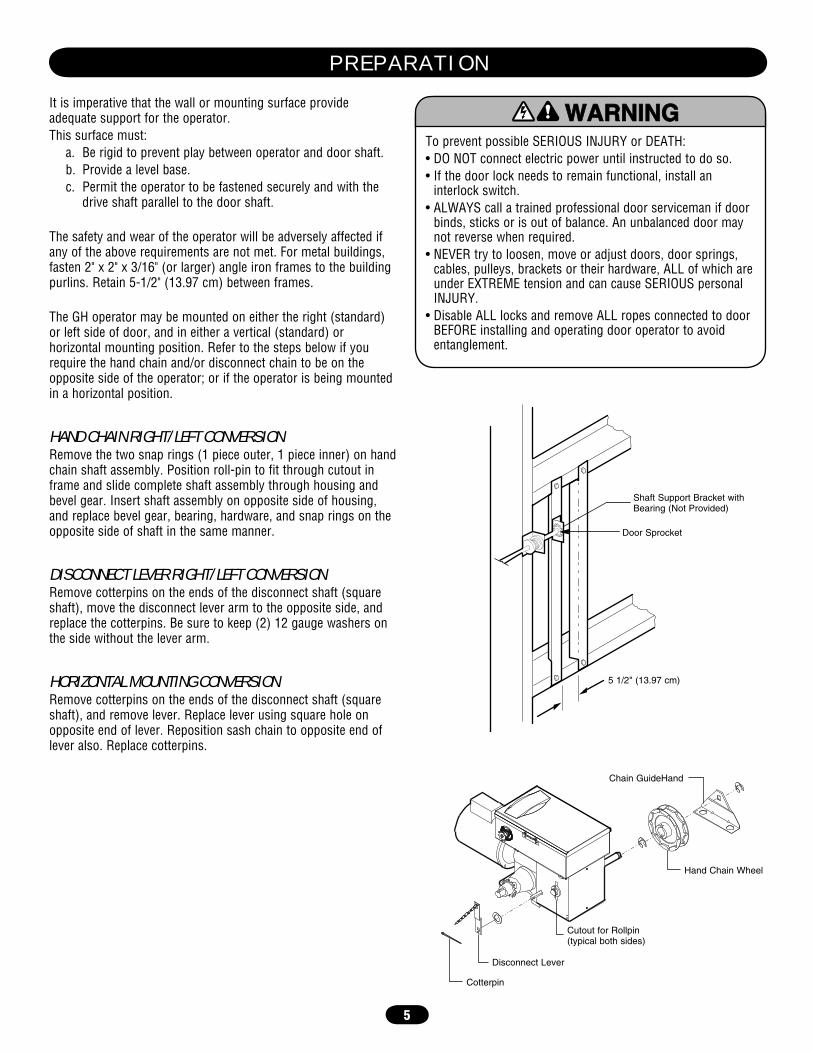
It is imperative that the wall or mounting surface provide adequate support for the operator.This surface must: a. Be rigid to prevent play between operator and door shaft. b. Provide a level base. c. Permit the operator to be fastened securely and with the
drive shaft parallel to the door shaft.
The safety and wear of the operator will be adversely affected if any of the above requirements are not met. For metal buildings, fasten 2" x 2" x 3/16" (or larger) angle iron frames to the building purlins. Retain 5-1/2" (13.97 cm) between frames.
The GH operator may be mounted on either the right (standard) or left side of door, and in either a vertical (standard) or horizontal mounting position. Refer to the steps below if you require the hand chain and/or disconnect chain to be on the opposite side of the operator; or if the operator is being mounted in a horizontal position.
HAND CHAIN RIGHT/LEFT CONVERSIONRemove the two snap rings (1 piece outer, 1 piece inner) on hand chain shaft assembly. Position roll-pin to fit through cutout in frame and slide complete shaft assembly through housing and bevel gear. Insert shaft assembly on opposite side of housing, and replace bevel gear, bearing, hardware, and snap rings on the opposite side of shaft in the same manner.
DISCONNECT LEVER RIGHT/LEFT CONVERSIONRemove cotterpins on the ends of the disconnect shaft (square shaft), move the disconnect lever arm to the opposite side, and replace the cotterpins. Be sure to keep (2) 12 gauge washers on the side without the lever arm.
HORIZONTAL MOUNTING CONVERSIONRemove cotterpins on the ends of the disconnect shaft (square shaft), and remove lever. Replace lever using square hole on opposite end of lever. Reposition sash chain to opposite end of lever also. Replace cotterpins.
To prevent possible SERIOUS INJURY or DEATH:• DO NOT connect electric power until instructed to do so.• If the door lock needs to remain functional, install an
interlock switch.• ALWAYS call a trained professional door serviceman if door
binds, sticks or is out of balance. An unbalanced door may not reverse when required.
• NEVER try to loosen, move or adjust doors, door springs, cables, pulleys, brackets or their hardware, ALL of which are under EXTREME tension and can cause SERIOUS personal INJURY.
• Disable ALL locks and remove ALL ropes connected to door BEFORE installing and operating door operator to avoid entanglement.
ATTENTION
AVERTISSEMENT AVERTISSEMENT
AVERTISSEMENT
WARNING
CAUTION
WARNING
WARNING WARNING
PRECAUCIÓN ADVERTENCIA
ADVERTENCIA ADVERTENCIA 5 1/2" (13.97 cm)
Door Sprocket
Shaft Support Bracket with Bearing (Not Provided)
Chain GuideHand
Cotterpin
Disconnect Lever
Cutout for Rollpin (typical both sides)
Hand Chain Wheel
P R E P A R A T I O N

6
IMPORTANT NOTE: Before your operator is installed, be sure the door has been properly aligned and is working smoothly. The operator may be wall mounted or mounted on a bracket or shelf. If necessary, refer to the preparation on page 5. Refer to the illustrations and instructions below that suit your application.
Optimum Distance 12 - 15" (30.5 - 38.1 cm)
Optimum Distance12 - 15" (30.5 - 38.1 cm)
Chain Keeper 4' (1.22 m) above floor
Be sure door sprocket is properly aligned with drive before securing to shaft.
Figure 1
Figure 2
MOUNT THE OPERATOR1. Wall Mount: The operator should generally be installed below
the door shaft, and as close to the door as possible (Figure 1).Bracket Shelf Mounting: The operator may be mounted either above or below the door shaft (Figure 2).
IMPORTANT: The shelf or bracket must provide adequate support, prevent play between operator and door shaft, and permit operator to be fastened securely and with the drive shaft parallel to the door shaft.NOTE: The optimum distance between the door shaft and operator drive shaft is between 12" - 15" (30.5 - 38.1 cm).2. Place door sprocket on the door shaft. Do not insert the key at
this time.3. Place drive sprocket on the appropriate side of the operator.
Do not insert the key at this time.4. Wrap drive chain around door sprocket and join roller chain
ends together with master link.5. Raise operator to approximate mounting position and position
chain over operator sprocket.6. Raise or lower operator until the chain is taut (not tight). Make
sure the operator output shaft is parallel to door shaft and sprockets are aligned. When in position, secure the operator to wall or mounting bracket.
7. Align sprockets and secure (Figure 3).8. Install Hand Chain
Place hand chain around hand chain wheel. Be sure to pass it through both openings in the chain guide. Remove enough links so chain hangs approximately 2' (.61 m) above the floor.
9. Mount Chain Keeper / Keyhole BracketUsing suitable hardware mount the chain keeper approximately 4' (1.22 m) above the floor, near the free hanging chain. Remove disconnect sash chain from bag and place the end through the keyhole in the chain keeper. Remove excess links if necessary.
Figure 3
Typical Right Hand Wall Mounted Operator
OPTIONALMounting Bracket
P/N 08-9098
I N S T A L L A T I O N

7
MANUAL OPERATIONThis operator has provisions for manually operating the door in case of emergency or power failure. These operators are equipped with a manual hoist. An electrical interlock will disable the electrical controls when the hoist is used.
To operate the hoist:
1. Pull the disconnect chain (small chain) to engage the interlock to disable the controls. The disconnect chain may be locked in position by slipping the end through the keyhole of the chain keeper mounted on the wall.
2. Operate the door in the desired direction by pulling on one side or the other of the continuous loop hoist chain (large chain).
3. The disconnect chain must be released from the chain keeper before the door will operate again electrically.
To prevent possible SERIOUS INJURY from a moving chain, ENGAGE interlock BEFORE manually operating your door.
ATTENTION
AVERTISSEMENT AVERTISSEMENT
AVERTISSEMENT
WARNING WARNING
CAUTION
WARNING
WARNING
PRECAUCIÓN ADVERTENCIA
ADVERTENCIA ADVERTENCIA
Chain Keeper (with pad locking provisions)
I N S T A L L A T I O N
8
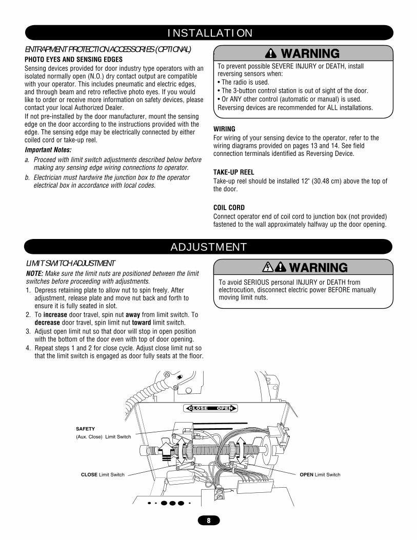
ENTRAPMENT PROTECTION ACCESSORIES (OPTIONAL)PHOTO EYES AND SENSING EDGESSensing devices provided for door industry type operators with an isolated normally open (N.O.) dry contact output are compatible with your operator. This includes pneumatic and electric edges, and through beam and retro reflective photo eyes. If you would like to order or receive more information on safety devices, please contact your local Authorized Dealer.If not pre-installed by the door manufacturer, mount the sensing edge on the door according to the instructions provided with the edge. The sensing edge may be electrically connected by either coiled cord or take-up reel.Important Notes:a. Proceed with limit switch adjustments described below before
making any sensing edge wiring connections to operator.b. Electrician must hardwire the junction box to the operator
electrical box in accordance with local codes.
WIRINGFor wiring of your sensing device to the operator, refer to the wiring diagrams provided on pages 13 and 14. See field connection terminals identified as Reversing Device.
TAKE-UP REELTake-up reel should be installed 12" (30.48 cm) above the top of the door.
COIL CORDConnect operator end of coil cord to junction box (not provided) fastened to the wall approximately halfway up the door opening.
To avoid SERIOUS personal INJURY or DEATH from electrocution, disconnect electric power BEFORE manually moving limit nuts.
ATTENTION
AVERTISSEMENT AVERTISSEMENT
AVERTISSEMENT
WARNING
CAUTION
WARNING
WARNING WARNING
PRECAUCIÓN ADVERTENCIA
ADVERTENCIA ADVERTENCIA
LIMIT SWITCH ADJUSTMENTNOTE: Make sure the limit nuts are positioned between the limit switches before proceeding with adjustments.1. Depress retaining plate to allow nut to spin freely. After
adjustment, release plate and move nut back and forth to ensure it is fully seated in slot.
2. To increase door travel, spin nut away from limit switch. To decrease door travel, spin limit nut toward limit switch.
3. Adjust open limit nut so that door will stop in open position with the bottom of the door even with top of door opening.
4. Repeat steps 1 and 2 for close cycle. Adjust close limit nut so that the limit switch is engaged as door fully seats at the floor.
CLOSE OPEN
SAFETY
(Aux. Close) Limit Switch
CLOSE Limit Switch OPEN Limit Switch
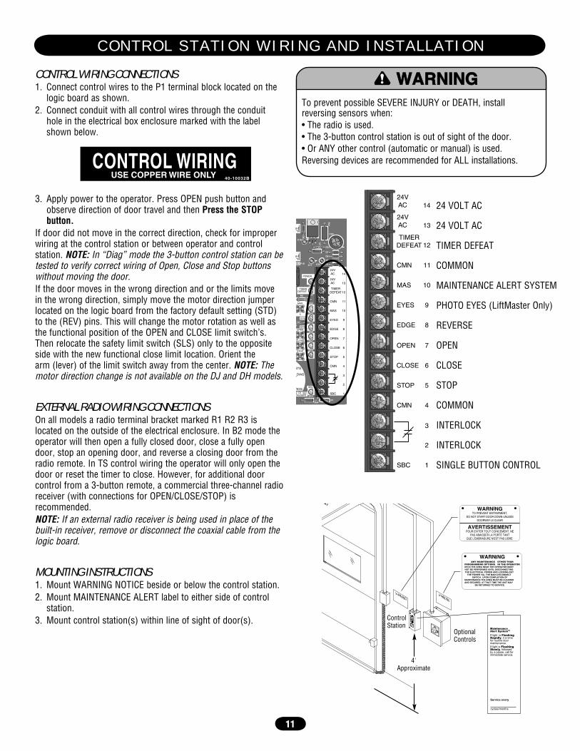
To prevent possible SEVERE INJURY or DEATH, install reversing sensors when:• The radio is used. • The 3-button control station is out of sight of the door.• Or ANY other control (automatic or manual) is used. Reversing devices are recommended for ALL installations.
ATTENTION
AVERTISSEMENT AVERTISSEMENT
AVERTISSEMENT
WARNING WARNING
CAUTION
WARNING
WARNING
PRECAUCIÓN ADVERTENCIA
ADVERTENCIA ADVERTENCIA
A D J U S T M E N T
I N S T A L L A T I O N

9
ADJUST TORQUE LIMITER CLUTCH(OPTIONAL MODIFICATION)1. Loosen set screws on clutch nut.2. Back off clutch nut until there is very little tension on the
clutch spring.3. Tighten clutch nut gradually until there is just enough tension
to permit the operator to move the door smoothly but to allow the clutch to slip if the door is obstructed. When the clutch is properly adjusted, it should generally be possible to stop the door by hand during travel.
BRAKE ADJUSTMENTThe brake is adjusted at the factory and should not need additional adjustment for the life of the brake assembly.
Replace brake assembly when necessary. Refer to the illustration for identification of components for the solenoid type brake system.
A D J U S T M E N T
(3) Set Screws
Brake Assembly
Actuator Plate
Solenoid
Brake Plate Assembly
Release Lever
10
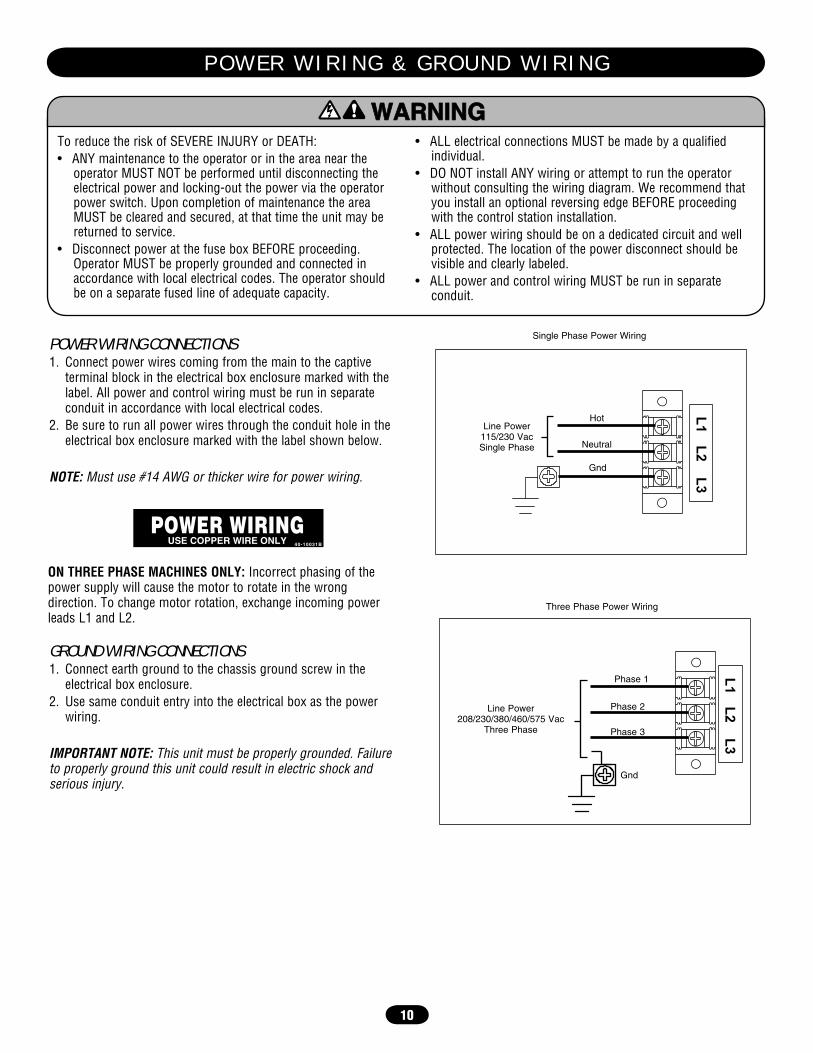
To reduce the risk of SEVERE INJURY or DEATH:• ANY maintenance to the operator or in the area near the
operator MUST NOT be performed until disconnecting the electrical power and locking-out the power via the operator power switch. Upon completion of maintenance the area MUST be cleared and secured, at that time the unit may be returned to service.
• Disconnect power at the fuse box BEFORE proceeding. Operator MUST be properly grounded and connected in accordance with local electrical codes. The operator should be on a separate fused line of adequate capacity.
• ALL electrical connections MUST be made by a qualified individual.
• DO NOT install ANY wiring or attempt to run the operator without consulting the wiring diagram. We recommend that you install an optional reversing edge BEFORE proceeding with the control station installation.
• ALL power wiring should be on a dedicated circuit and well protected. The location of the power disconnect should be visible and clearly labeled.
• ALL power and control wiring MUST be run in separate conduit.
P O W E R W I R I N G & G R O U N D W I R I N G
ATTENTION
AVERTISSEMENT AVERTISSEMENT
AVERTISSEMENT
WARNING
CAUTION
WARNING
WARNING WARNING
PRECAUCIÓN ADVERTENCIA
ADVERTENCIA ADVERTENCIA
POWER WIRING CONNECTIONS1. Connect power wires coming from the main to the captive
terminal block in the electrical box enclosure marked with the label. All power and control wiring must be run in separate conduit in accordance with local electrical codes.
2. Be sure to run all power wires through the conduit hole in the electrical box enclosure marked with the label shown below.
NOTE: Must use #14 AWG or thicker wire for power wiring.
ON THREE PHASE MACHINES ONLY: Incorrect phasing of the power supply will cause the motor to rotate in the wrong direction. To change motor rotation, exchange incoming power leads L1 and L2.
GROUND WIRING CONNECTIONS1. Connect earth ground to the chassis ground screw in the
electrical box enclosure.2. Use same conduit entry into the electrical box as the power
wiring.
IMPORTANT NOTE: This unit must be properly grounded. Failure to properly ground this unit could result in electric shock and serious injury.
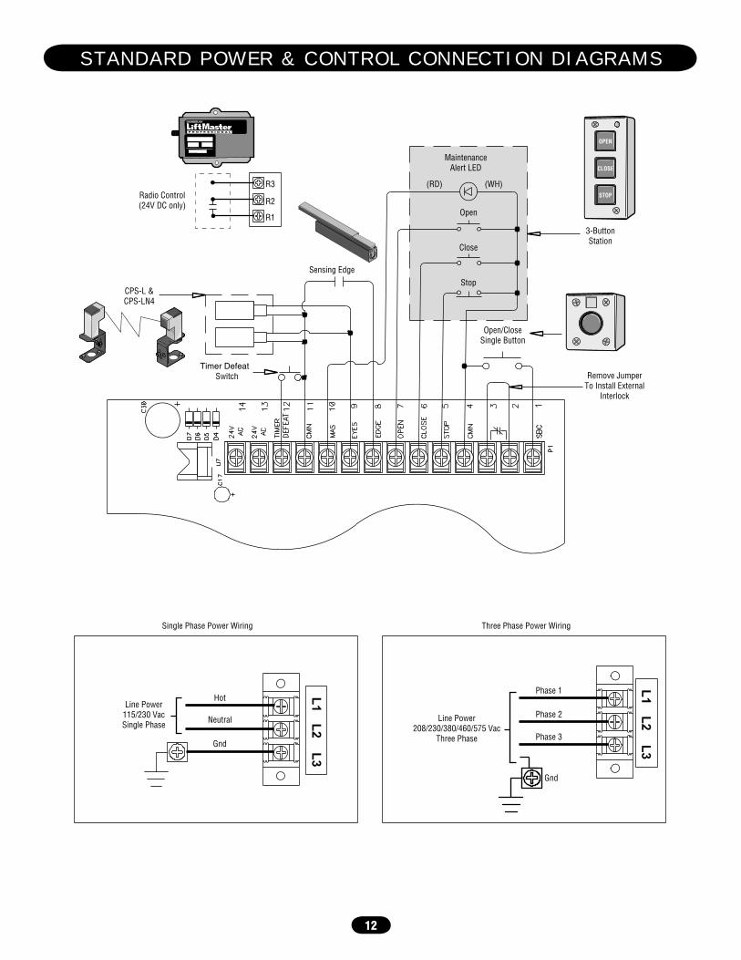
Single Phase Power Wiring
Line Power 115/230 Vac Single Phase
Gnd
Neutral
Hot
Line Power 208/230/380/460/575 Vac
Three Phase Phase 3
Phase 2
Phase 1
Gnd
Three Phase Power Wiring
11
CONTROL WIRING CONNECTIONS1. Connect control wires to the P1 terminal block located on the
logic board as shown.2. Connect conduit with all control wires through the conduit
hole in the electrical box enclosure marked with the label shown below.
3. Apply power to the operator. Press OPEN push button and observe direction of door travel and then Press the STOP button.
If door did not move in the correct direction, check for improper wiring at the control station or between operator and control station. NOTE: In “Diag” mode the 3-button control station can be tested to verify correct wiring of Open, Close and Stop buttons without moving the door.If the door moves in the wrong direction and or the limits move in the wrong direction, simply move the motor direction jumper located on the logic board from the factory default setting (STD) to the (REV) pins. This will change the motor rotation as well as the functional position of the OPEN and CLOSE limit switch’s. Then relocate the safety limit switch (SLS) only to the opposite side with the new functional close limit location. Orient the arm (lever) of the limit switch away from the center. NOTE: The motor direction change is not available on the DJ and DH models.
EXTERNAL RADIO WIRING CONNECTIONSOn all models a radio terminal bracket marked R1 R2 R3 is located on the outside of the electrical enclosure. In B2 mode the operator will then open a fully closed door, close a fully open door, stop an opening door, and reverse a closing door from the radio remote. In TS control wiring the operator will only open the door or reset the timer to close. However, for additional door control from a 3-button remote, a commercial three-channel radio receiver (with connections for OPEN/CLOSE/STOP) is recommended.NOTE: If an external radio receiver is being used in place of the built-in receiver, remove or disconnect the coaxial cable from the logic board.
MOUNTING INSTRUCTIONS1. Mount WARNING NOTICE beside or below the control station.2. Mount MAINTENANCE ALERT label to either side of control
station.3. Mount control station(s) within line of sight of door(s).
CONTROL WIRINGUSE COPPER WIRE ONLY 40-10032B
OR IN THE AREA NEAR THE OPERATOR MUST NOT BE PERFORMED UNTIL DISCONNECTING THE ELECTRICAL POWER AND LOCKING-OUT
THE POWER VIA, THE MAIN DISCONNECT SWITCH. UPON COMPLETION OF
MAINTENANCE THE AREA MUST BE CLEARED AND SECURED, AT THAT TIME THE UNIT MAY
BE RETURNED TO SERVICE.
MaintenanceAlert SystemTM
If light is FlashingRapidly, it is timefor routine doormaintenance.If light is FlashingSlowly, followedby a pause, call forimmediate service.
Service every
cycles/months
4'Approximate
ControlStation
OptionalControls
POWER
TIMERDEFEAT
MAS
4
STS
DIAG
ROG
24VAC
24VAC
TIMERDEFEAT
CMN
MAS
EYES
EDGE
OPEN
CLOSE
STOP
CMN
SBC
11
10
9
14
13
12
8
7
6
5
4
3
2
1
CLOSE
STOP
OPENEDGE
EYES
P1
D34F1
2 D1 E2)FAILSAFE
D23
D151
R8
C18
D8
U7
R31
D31
C3Ø
D7
D6
D5
D4C25C17P1Ø
A
D2Ø
D21
D13
D14
D28
D17
D19
SBC
24VAC
24VAC
TIMERDEFEAT
CMN
MAS
EYES
EDGE
OPEN
CLOSE
STOP
CMN
SBC
11
10
9
14
13
12
8
7
6
5
4
3
2
1
24 VOLT AC
24 VOLT AC
TIMER DEFEAT
COMMON
MAINTENANCE ALERT SYSTEM
PHOTO EYES (LiftMaster Only)
REVERSE
OPEN
CLOSE
STOP
COMMON
INTERLOCK
INTERLOCK
SINGLE BUTTON CONTROL
To prevent possible SEVERE INJURY or DEATH, install reversing sensors when:• The radio is used. • The 3-button control station is out of sight of the door.• Or ANY other control (automatic or manual) is used. Reversing devices are recommended for ALL installations.
ATTENTION
AVERTISSEMENT AVERTISSEMENT
AVERTISSEMENT
WARNING WARNING
CAUTION
WARNING
WARNING
PRECAUCIÓN ADVERTENCIA
ADVERTENCIA ADVERTENCIA
C O N T R O L S T A T I O N W I R I N G A N D I N S T A L L A T I O N
12
Open
Close
Stop
MaintenanceAlert LED
Open/CloseSingle Button
(WH)(RD)
Sensing Edge
CPS-L &CPS-LN4
Timer DefeatSwitch
R1
R2
R3Radio Control(24V DC only)
Neutral
Hot
Gnd
Remove JumperTo Install External
Interlock
Single Phase Power Wiring Three Phase Power Wiring
Phase 1
Phase 2
Phase 3
Gnd
Line Power208/230/380/460/575 Vac
Three Phase
Line Power115/230 VacSingle Phase
3-ButtonStation
OPEN
CLOSE
STOP
S T A N D A R D P O W E R & C O N T R O L C O N N E C T I O N D I A G R A M S
13
U1
PO
WE
R
TIM
ER
D
EF
EAT
MA
S
4
MR
T
1 R
AD
IO
MID
2
TIM
ER
TIM
ER
E
NA
BLE
T
TS
FS
TS
E
2
RE
LAY
A
RE
LAY
B
D1
DIA
G
C2 B
2 P
RO
G
3
24V
A
C
24V
A
C
TIM
ER
D
EF
EAT
CM
N
MA
S
EY
ES
ED
GE
OP
EN
CLO
SE
STO
P
CM
N
SB
C
11
10
9 14
13
12
8 7 6 5 4 3 2 1
CLO
SE
STO
P
OP
EN
E
DG
E
OLS
MID
SLS
MOTOR DIRECTION
CLS
D25
D24
D26
D27
D36
C77
C73
C54
C78
L1 L5
P6
D35
S8
D16
P7
EY
ES
K3
P1
D34
F1
FAIL
SA
FE
( B
2 C
2 D
1 E
2)
NO
N F
AIL
SA
FE
D23
D15
D1
D22
R8
J1
X1
E1 R29
C18
D8
U7
R31
D31
C3Ø
D7
D6
D5
D4
C25
C17
C11
D3 Ø
2P
1 Ø
P4
Ø1
4L
GØ
65
7–
A
Ø1
4G
PØ
65
7–
A
J3Ø
Ø
D2Ø
D21
D13
D14
D28
D17
D19
SB
C
C71
®
Remove JumperTo Install External
Door Interlock
3-ButtonStation
MaintenanceAlert LED
(RD) (WH)
Open
Close
Stop
Open/CloseSingle Button
SensingEdge
CPS-L & CPS-LN4
Hoist InterlockWhen Present TMR DEF
SWITCH
MOV
MOV
(YE) (BL)
(YE)
(OR) (WH) (YE) (PU) (WH) (RD) (GY) (YE) (RD) (WH) (PU) (YE) (OR)
(GY)
(OR) (PU)
(WH) (WH)
(WH)
(WH)
(WH)
(PU) (YE)
(WH)
(WH)
(WH)
(WH)
(YE)
115
/ 230
VOLT
1PH
.PO
WER
IN
hot
neutral
ground
(BK)
COM 120 VAC
120 / 240 VAC
+24 VAC -24 VAC See MotorConnections
8
0 1
4
6 2 6 2
8 4
0 1
COIL
COM
NO
C
B A
(WH)
(BL) (GY)
(YE)
(BR)
(GY)
See MotorConnections
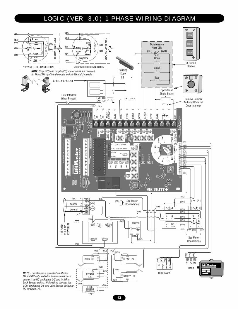
NOTE: Lock Sensor is provided on Models DJ and DH only, red wire from main harness connects to NC on Bypass L/S and to NO on Lock Sensor switch. White wires connect the COM on Bypass L/S and Lock Sensor switch to NC on Open L/S.
OPEN
CLOSE
STOP
NOTE: Gray (GY) and purple (PU) motor wires are reversedfor H and HJ right hand models and all GH and J models.
115V MOTOR CONNECTION 230V MOTOR CONNECTION
(WH)
(WH)
(WH)(RD) (PU)
(YE)
COMNO
NC
NO
NC
COM
NO
NC
COM
OPEN L/S
NO
NC
LOCKSENSOR
(see note at left)
CLOSE L/S
SAFETY L/S
(WH)(RD)
NO
NC
COM
BYPASSL/S
(WH)
(RD)
(WH
)
(RD
)
(YE
)
(GY
)
(WH
)
(OR
)
(YE
)
1 2 3 4
RPM Board
Radio
R1 R2 R3
L3
L2
L1
L O G I C ( V E R . 3 . 0 ) 1 P H A S E W I R I N G D I A G R A M

14
U1
PO
WE
R
TIM
ER
D
EF
EAT
MA
S
4
MR
T
1 R
AD
IO
MID
2
TIM
ER
TIM
ER
E
NA
BLE
T
TS
FS
TS
E
2
RE
LAY
A
RE
LAY
B
D1
DIA
G
C2 B
2 P
RO
G
3
24V
A
C
24V
A
C
TIM
ER
D
EF
EAT
CM
N
MA
S
EY
ES
ED
GE
OP
EN
CLO
SE
STO
P
CM
N
SB
C
11
10
9 14
13
12
8 7 6 5 4 3 2 1
CLO
SE
STO
P
OP
EN
E
DG
E
OLS
MID
SLS
MOTOR DIRECTION
CLS
D25
D24
D26
D27
D36
C77
C73
C54
C78
L1 L5
P6
D35
S8
D16
P7
EY
ES
K3
P1
D34
F1
FAIL
SA
FE
( B
2 C
2 D
1 E
2)
NO
N F
AIL
SA
FE
D23
D15
D1
D22
R8
J1
X1
E1 R29
C18
D8
U7
R31
D31
C3Ø
D7
D6
D5
D4
C25
C17
C11
D3Ø
2P
1Ø
P4
Ø1
4L
GØ
65
7–
A
Ø1
4G
PØ
65
7–
A
J3Ø
Ø
D2Ø
D21
D13
D14
D28
D17
D19
SB
C
C71
®
Remove JumperTo Install External
Door Interlock
3-ButtonStation
MaintenanceAlert LED
(RD) (WH)
Open
Close
Stop
Open/CloseSingle Button
SensingEdge
CPS-L & CPS-LN4
Hoist InterlockWhen Present TMR DEF
SWITCH
MOV
MOV
NOTE: Lock Sensor is provided on Models DJ and DH only, red wire from main harness connects to NC on Bypass L/S and to NO on Lock Sensor switch. White wires connect the COM on Bypass L/S and Lock Sensor switch to NC on Open L/S.
(WH)
(WH)
(WH)(RD) (PU)
(YE)
COMNO
NC
NO
NC
COM
NO
NC
COM
OPEN L/S
NO
NC
LOCKSENSOR
(see note at left)
CLOSE L/S
SAFETY L/S
(WH)(RD)
NO
NC
COM
BYPASSL/S
(WH)
(RD)
(YE) (BL)
(YE)
(OR) (WH) (YE) (PU) (WH) (RD) (GY) (YE) (RD) (WH) (PU) (YE) (OR)
(GY)
(OR) (PU)
(WH) (WH) (WH)
(WH)
(WH)
(WH)
(GY) (YE)
(WH)
(GY)
(WH)
(WH)
(WH)
(WH) (WH)
(PU) (BR) (BR)
(YE) 208/
230
/ 38
0 / 4
60VO
LT 3
PH.
POW
ER IN
(BK)
COM 120 VAC
240 / 460 / 575 VAC
+24 VAC -24 VAC
COIL COIL
COM COM
NO NO
See MotorConnections
See MotorConnections
8
0 1
4
6 2 6 2
8 4
0 1 AB
CD
OPEN
CLOSE
STOP
NOTE: Gray (GY) and purple (PU) motorwires are reversed for H and HJ right handmodels and all GH and J models.
575V
BRA
KE(W
HEN
PRES
ENT) 1
2
3
(GY)(BR)
(PU)
(BR)
(BL/BK)
(BL/BK)
(YE)230V
BRA
KE(W
HEN
PRES
ENT)
JT4 T7 T1
T5 T8 T2
T6 T9 T3
(GY)(BR)
(PU)
(BR)(YE)J 23
0V B
RAKE
(WHE
N PR
ESEN
T)
JT4 T7 T1
T5 T8 T2
T6 T9 T3
(GY)(BR)
(PU)
(BR)(YE)J
208/230V MOTOR CONNECTION 460V MOTOR CONNECTION 575V MOTOR CONNECTION
(WH
)
(RD
)
(YE
)
(GY
) (WH
)
(OR
)
(YE
)
1 2 3 4
RPM BoardRadio
R1 R2 R3
L3
L2
L1
L O G I C ( V E R . 3 . 0 ) 3 P H A S E W I R I N G D I A G R A M

15
U1
POWER
TIMERDEFEAT
MAS
4
MRT
1RADIO
MID
2
TIMER
TIMERENABLE
T TS
FSTSE2
RELAY A
RELAY B
D1 DIAG
C2
B2 PROG
3
24VAC
24VAC
TIMERDEFEAT
CMN
MAS
EYES
EDGE
OPEN
CLOSE
STOP
CMN
SBC
11
10
9
14
13
12
8
7
6
5
4
3
2
1
CLOSE
STOP
OPENEDGE
OLS
MID
SLS
MO
TOR
DIR
EC
TIO
N
RE
V�
ST
D�
CLS
D25
D24
D26
D27
D36
C77
C73
C54
C78
L1
L5
P6
D35
S8
D16
P7
EYES
K3
P1
D34F1
FAILSAFE (B2 C2 D1 E2)NON FAILSAFE
D23
D15D1
D22
R8
J1
X1
E1
R29
C18
D8
U7
R31
D31
C3Ø
D7
D6
D5
D4C25C17
C11
D3Ø2 P1Ø
P4
Ø14LGØ657–A Ø14GPØ657–A
J3ØØ
D2Ø
D21
D13
D14
D28
D17
D19
CO
NTA
CTO
R/3
PH
�
SIN
GLE
PH
AS
E
�
SBCC71
®
Wiring Type Selector Dial
Failsafe Switch
Maximum Run Timer Button
Auxiliary Board Connections
Programmed Chip
Mid Stop Learn Button
Timer to Close Learn Button
Radio Learn Button
Open Button
Close Button
Stop Button
Control Wiring Terminal Block
Motor Direction Jumper
Maintenance Alert System Button for Programming
Single Phase and Three Phase Jumper
L O G I C B O A R D
16
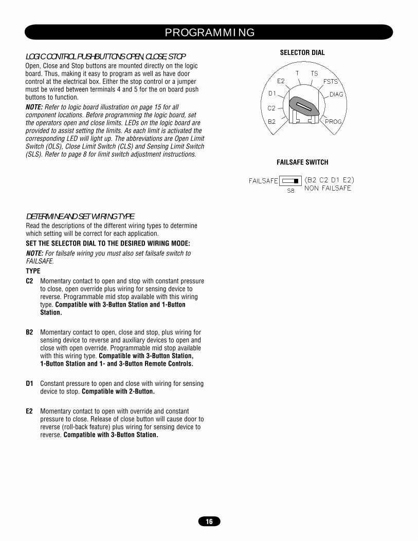
DETERMINE AND SET WIRING TYPERead the descriptions of the different wiring types to determine which setting will be correct for each application.SET THE SELECTOR DIAL TO THE DESIRED WIRING MODE: NOTE: For failsafe wiring you must also set failsafe switch to FAILSAFE.TYPEC2 Momentary contact to open and stop with constant pressure
to close, open override plus wiring for sensing device to reverse. Programmable mid stop available with this wiring type. Compatible with 3-Button Station and 1-Button Station.
B2 Momentary contact to open, close and stop, plus wiring for sensing device to reverse and auxiliary devices to open and close with open override. Programmable mid stop available with this wiring type. Compatible with 3-Button Station, 1-Button Station and 1- and 3-Button Remote Controls.
D1 Constant pressure to open and close with wiring for sensing device to stop. Compatible with 2-Button.
E2 Momentary contact to open with override and constant pressure to close. Release of close button will cause door to reverse (roll-back feature) plus wiring for sensing device to reverse. Compatible with 3-Button Station.
LOGIC CONTROL PUSHBUTTONS OPEN, CLOSE, STOPOpen, Close and Stop buttons are mounted directly on the logic board. Thus, making it easy to program as well as have door control at the electrical box. Either the stop control or a jumper must be wired between terminals 4 and 5 for the on board push buttons to function.NOTE: Refer to logic board illustration on page 15 for all component locations. Before programming the logic board, set the operators open and close limits. LEDs on the logic board are provided to assist setting the limits. As each limit is activated the corresponding LED will light up. The abbreviations are Open Limit Switch (OLS), Close Limit Switch (CLS) and Sensing Limit Switch (SLS). Refer to page 8 for limit switch adjustment instructions.
SELECTOR DIAL
FAILSAFE SWITCH
P R O G R A M M I N G
17
FAILSAFE WIRING TYPESTYPETS Momentary contact to open, close, and stop with
open override and Timer To Close. Every device that causes door to open, including a reversing device, activates the Timer To Close. Auxiliary controls can be connected to open input to activate the Timer To Close. If the timer has been activated, the open button and radio control can recycle the timer. The stop button will deactivate the Timer To Close until the next command input. The Timer To Close will function from the programmable mid stop with this wiring type. Compatible with 3-Button Station,1-Button Station and 1- and 3-Button Remote Controls. (NOTE: Requires self monitoring photo eyes to operate.)
T Momentary contact to open, close, and stop, with open override and Timer To Close. Every device that causes the door to open, except a reversing device, activates the Timer To Close. Auxiliary controls can be connected to open input to activate the Timer To Close. If the Timer To Close has been activated, the open button and radio control can recycle the timer. The stop button will deactivate the timer until the next command input. The Timer to Close will function from the programmable mid stop with this wiring type. Compatible with 3-Button Station,1-Button Station and 1- and 3-Button Remote Controls. (NOTE: Requires self monitoring photo eyes to operate.)
FSTS Momentary button contact for open, close and stop programming. Radio controls allowing open, close and stop. User set mid stop. User set Timer To Close. The single button station opens the door to the full open limit bypassing the mid stop and activates the Timer To Close, putting the operator in TS mode until the door reaches the down limit, or is stopped in travel. At which time the operator enters the B2 mode. Compatible with 3-Button Station, 1-Button Station and 1- and 3-Button Remote Controls. (NOTE: Requires self monitoring photo eyes to operate this feature/wire type.)
C2 Failsafe Same functions as C2. Self Monitoring safety device must be installed to operate door for each of the following failsafe wiring types. See Self Monitoring Safety Device Options. Compatible with 3-Button Station, 1-Button Station and 1- and 3-Button Remote Controls.
SELF-MONITORING SAFETY DEVICE OPTIONSTo use the operator in any of the Failsafe wiring modes, or Timer To Close wiring modes (TS, T, FSTS), a self monitoring safety device or CPS3 card with photo eyes or safety edges must be installed.
RECOMMENDED SELF-MONITORING SAFETY DEVICES:CPS-L NEMA 1 Direct Connect EyesCPS-LN4 NEMA 4 Direct Connect Eyes
IMPORTANT NOTES:1. External interlocks may be used with all functional modes.2. Auxiliary devices are any devices that have only dry contacts.
Examples: photocell, loop detector, pneumatic or electrical treadles, radio controls, one button stations, pull cords, etc.
3. Open override means that the door may be reversed while closing by activating an opening device without the need to use the stop button first.
B2 Failsafe Same functions as B2. Self Monitoring safety device must be installed to operate door for each of the following failsafe wiring types. See Self Monitoring Safety Device Options. Compatible with 3-Button Station, 1-Button Station and 1- and 3-Button Remote Controls.
D1 Failsafe Same functions as D1. Self Monitoring safety device must be installed to operate door for each of the following failsafe wiring types. See Self Monitoring Safety Device Options. Compatible with 2-Button Station and 2-Button Remote Control.
E2 Failsafe Same functions as E2. Self Monitoring safety device must be installed to operate door for each of the following failsafe wiring types. See Self Monitoring Safety Device Options. Compatible with 3-Button Station and 3-Button Remote Control.
P R O G R A M M I N G

18
SINGLE BUTTON REMOTE CONTROL PROGRAMMED AS A SINGLE BUTTON CONTROL (SBC)This function programs a remote control as a wireless single button control. This function will work in the following modes:
In B2 mode, operation is OPEN/STOP/CLOSE/REVERSE/STOP.In C2 mode, operation is OPEN/STOP/constant pressure to CLOSE/STOP on release.In T and TS modes, operation is OPEN/STOP/CLOSE/REVERSE/STOP and Timer to Close start/refresh. NOTE: If Car Dealer mode is enabled, SBC will be open only stopping at the Open Mid-Stop.In FSTS mode, operation is OPEN with Timer to Close start/refresh only, bypassing a programmed Open Mid-Stop.
1. Press and release the RADIO button on the logic board (LED will light).
2. Press and release the SBC externally wired button or TIMER on the logic board (LED flashes rapidly and then remains on solid).
3. Press and hold the remote control button until the LED flashes rapidly. The LED will then remain on solid after releasing.
4. Press and release the RADIO button on the logic board (LED flashes rapidly and then turns off). The programming mode is exited if no activity is performed within 30 seconds.
NOTE: Requires self-monitoring photo eyes when using constant pressure to close (wiring C2, D1 and E2 ).ERASING REMOTE CONTROLSPress and hold the RADIO button on the logic board until the RADIO LED flashes rapidly (approximately 5 seconds).All remote controls will be erased.
STANDARD SINGLE BUTTON REMOTE CONTROLBuilt in 3-channel, 315MHz radio receiver allows you to add as many as 23 Security✚® remote controls or dip switch remote controls.
PROGRAMMING REMOTE CONTROLSSTANDARD SINGLE BUTTON REMOTE CONTROL1. To enter programming, press and release the RADIO button on
the logic board (LED will light).2. Press and hold the remote control button until the LED flashes
rapidly, then release remote control button. The LED will then remain on solid after releasing the button. Repeat to add additional remote control(s).
3. Press and release the RADIO button to complete the programming. The programming mode is exited if no activity is performed within 30 seconds.
NOTE: Single button remote control is not supported with D1 and E2 wiring modes.
L i f t M a s t e r
U1
MRT
1 RADIO
MID
2
T
E2
RELA
RELA
D1
C2
B2
OLS
MID
SLS
RE
V
CLS
D25
D24
D26
D27
D36
C77
C73
C54
C78
L1
L5
P6
D35
D16
P7
K3
FAILSAF
X1
E1
R29
C11
D3Ø2
P4
Ø14LGØ6
C71
®
RADIO
NOTICE: To comply with FCC and or Industry Canada (IC) rules, adjustment or modifications of this receiver and/or transmitter are prohibited, except for changing the code setting or replacing the battery. THERE ARE NO OTHER USER SERVICEABLE PARTS.Tested to Comply with FCC Standards FOR HOME OR OFFICE USE. Operation is subject to the following two conditions: (1) this device may not cause harmful interference, and (2) this device must accept any interference received, including interference that may cause undesired operation.
To prevent possible SEVERE INJURY or DEATH, install reversing sensors when:• The radio is used. • The 3-button control station is out of sight of the door.• Or ANY other control (automatic or manual) is used. Reversing devices are recommended for ALL installations.
ATTENTION
AVERTISSEMENT AVERTISSEMENT
AVERTISSEMENT
WARNING WARNING
CAUTION
WARNING
WARNING
PRECAUCIÓN ADVERTENCIA
ADVERTENCIA ADVERTENCIA
P R O G R A M M I N G

19
3-BUTTON REMOTE CONTROLS
Your 315MHz Security✚®or dip switch remote control can be programmed to operate as a 3-button wireless control station: the large button will open the door, the middle button will close the door, and the third button will stop the door’s movement. You may set up this feature as follows:1. To enter programming press the RADIO button on the logic
board (the RADIO LED will light).2. To program the OPEN button to a remote control press the
OPEN button on the logic board. The RADIO LED will flash and then stay on solid. Then press the corresponding button on the remote control. The RADIO LED on the logic board will flash, this confirms that the remote control has been programmed. (By programming the remote control you use 1 channel of the 23 channels on the radio receiver.)
3. To program the CLOSE button to a remote control press the CLOSE button on the logic board. The RADIO LED will flash and then stay on solid. Then press the corresponding button on the remote control. The RADIO LED on the logic board will flash, this confirms that the remote control has been programmed. (By programming the remote control you use 1 channel of the 23 channels on the radio receiver.)
4. To program the STOP button to a remote control, press the STOP button on the logic board. The RADIO LED will flash and then stay on solid. Then press the corresponding button on the remote control. The RADIO LED on the logic board will flash, this confirms that the remote control has been programmed. (By programming the remote control you use 1 channel of the 23 channels on the radio receiver.)
5. After learning remote controls press the RADIO button on the logic board (LED will turn off). NOTE: If no activity within 30 seconds the radio will automatically exit programming mode.
OPEN
CLOSE
STOP
U1
POWER
TIMERDEFEAT
MAS
4
MRT
1 RADIO
MID
2
TIMER
TIMERENABLE
T TS
FSTSE2
RELAY A
RELAY B
D1 DIAG
C2
B2 PROG
3
24VAC
24V AC
TIMERDEFEAT
CMN
MAS
EYES
EDGE
OPEN
CLOSE
STOP
CMN
SBC
11
10
9
14
13
12
8
7
6
5
4
3
2
1
CLOSE
STOP
OPENEDGE
OLS
MID
SLS
MO
TOR
DIR
EC
TIO
N
RE
V�
ST
D�
CLS
D25
D24
D26
D27
D36
C77
C73
C54
C78
L1
L5
P6
D35
S8
D16
P7
EYES
K3
P1
D34F1
FAILSAFE (B2 C2 D1 E2)NON FAILSAFE
D23
D15D1
D22
R8
J1
X1
E1
R29
C18
D8
U7
R31
D31
C3Ø
D7
D6
D5
D4C25C17
C11
D3Ø2 P1Ø
P4
Ø14LGØ657–A Ø14GPØ657–A
J3ØØ
D2Ø
D21
D13
D14
D28
D17
D19
CO
NTA
CTO
R/3
PH
�
SIN
GLE
PH
AS
E
�
SBCC71
®
CLOSE
STOP
OPEN EDGE D1
D22D2Ø
D21
D13
Open
Close
Stop
REMOTE CONTROL PROGRAMMING FEATUREProgram Remote Controls from the 3-button control station (3BCS). Requires Firmware Version 4.6 or higher and a 3BCS with the MAS connected to the control board.This feature allows the user to add additional remote controls from the 3BCS. By default the remote control learn option is off. NOTE: Requires access to the operator electrical box to enable or disable this feature.To turn this feature on:1. Turn the SELECTOR DIAL to PROG.2. Press and release the RADIO button. The RADIO LED will be lit.3. Press and release the MID button. The RADIO LED will flash
quickly 6 times.4. Press and release the RADIO button. The RADIO LED will turn
off.5. Return the SECTOR DIAL to the desired wiring type.To add remote controls from the 3BCS:1. With the door in the fully closed position (close limit activated),
press and hold STOP.2. While holding STOP, press and hold CLOSE.3. While holding STOP and CLOSE, press and hold OPEN.4. Release all three buttons once the MAS LED has lit.5. Learn a remote control by one of the following methods:
a. Programming a standard single button/single function remote control, push and hold the remote control button until the MAS LED goes out. Repeat steps 1 through 4 to add additional remote controls.
b. Programming a 3-button/three function remote control (open/close/stop), first push the button on the 3BCS (example: OPEN) and then press and hold the button on the remote control (example: large button) that you want to correspond with the selected (example: OPEN) command until the MAS LED flashes and goes out. Repeat steps 1 through 4 to add additional buttons (close and stop).
To turn this feature off:1. Turn the SECTOR DIAL to PROG.2. Press and release the RADIO button. The RADIO LED will be lit.3. Press and release the MRT button. The RADIO LED will flash
quickly 3 times.4. Press and release RADIO button. The RADIO LED will turn off.5. Return SELECTOR DIAL to desired wiring type.NOTE: Restoring the operator to Factory Default (see “RESETTING FACTORY DEFAULTS”) will also disable this feature. The remote controls will still be learned.
P R O G R A M M I N G

20
MAINTENANCE ALERT SYSTEM (MAS)Feature: An internal cycle counter will activate a flashing LED on the 3-button control station when the preset number of cycles or months has elapsed (whichever occurs first). Setting this feature is optional. By default this feature will never activate. Logic 3.0 operators incorporate a self diagnostic feature built into the MAS LED. In addition to indicating when routine maintenance is due, the MAS LED can be used to troubleshoot some problems with the operator.Benefit: The Maintenance Alert System (MAS) assists the installing dealer in setting up a routine maintenance program. Once programmed, the MAS notifies the end user (with a flashing LED on the 3-button station) when a preset number of cycles/months has elapsed and scheduled maintenance is due.To Program:1. The Maintenance Alert System (MAS) assists the installing
dealer in setting up a routine maintenance program. Once programmed, the MAS notifies the end user (with a flashing LED on the 3-button station) when a preset number of cycles/months has elapsed and scheduled maintenance is due.
2. Close the door.3. Turn the selector dial to PROGRAM.4. Press and release the MAS SET button.5. Press the STOP button once to clear the MAS counter.6. Press the OPEN button once for every 5,000 cycles
increments. Press the CLOSE button once for every 3 month increments. Press the STOP button once to clear the MAS memory.
7. Press the MAS SET button to complete the programming. The on board LED will flash back the programmed settings. The OPEN LED will flash once for every 5,000 cycles. The CLOSE LED will flash once for every 3 months.
8. Turn the selector dial back to the desired wiring type.NOTE: If MAS LED flashes 2 or more flashes in a row followed by a pause, an operator error occurred. Turn to page 28 to diagnose problem.Example: A door is installed with 30,000 cycle springs and has an annual service contract. To set the MAS, turn selector dial to PROGRAM, press MAS button, press the STOP button to clear the memory and then press the OPEN button 6 times (30,000 cycles) and close 4 times (12 months). Press the MAS again to complete the programming. Set the selector dial to desired wiring type.
Special Notes about MAS: A 5th wire must be run to the control station to activate the MAS LED. The MAS LED on the logic board is always enabled. When the operator is serviced after the MAS LED has started to flash, repeat the setup procedure to program in the number or cycles desired until the next service visit OR press and hold the MAS button for 5 seconds in the PROGRAM mode to reset the MAS with its current programmed value. To disable the MAS, follow the programming procedure above and press the STOP button to reset the counter to zero. Every time the operator leaves the close limit is counted as one cycle.
Operation will vary depending on wiring type
SELECTOR DIAL
3-BUTTON STATION
OPEN
CLOSE
STOP
Maintenance Alert LED
To view how many cycles are programmed into the MAS, set the selector dial to DIAGNOSTIC and press the MAS button. The OPEN button LED will flash once for every 5,000 cycle increment programmed and the CLOSE button LED will flash once for every 3 month increment programmed.To view how many cycles have elapsed since the last time the MAS was programmed, set the selector dial to “Diagnostic” and press the “MAS” button. Press the OPEN button; the OPEN LED will flash once for every 5,000 cycles that has elapsed. Press the CLOSE button; the CLOSE LED will flash once for every (3) months that has elapsed. Press the MAS button to exit.
Press This To Get This
OPEN Adds 5,000 cycles to Maintenance Alert System Activation Counter.
CLOSE Adds 3 Months to Maintenance Alert System Activation Timer.
STOP Clears memory, sets Maintenance Alert System Activation Counter to 0 cycles and 0 months.
P R O G R A M M I N G

21
Operation will vary depending on wiring type
SELECTOR DIAL
Operation will vary depending on wiring type
SELECTOR DIAL
OPEN MID STOPFeature: The mid stop feature is to open the door to a preset point prior to the fully open position.Benefit: The door opens to a midpoint between open and close reducing heating and cooling costs. The door will not cycle fully, providing longer door and operator life.To Program:1. Close the door.2. Turn selector dial to “PROGRAM.”3. Press the “MID SET” button on logic board.4. Press the OPEN button, wait until the door reaches the desired
mid stop height, then press the STOP button.5. Press the MID SET button to complete programming.6. Turn selector dial back to desired wiring type.NOTE: A momentary open command will open the door fully from the “Mid Stop” position. Once at the “Mid Stop,” Photo eyes and other safety devices will not open the door beyond the mid stop position, except in E2 mode. The Timer to Close will work from the Mid Stop.To clear the Mid Stop set the selector dial to Program and press and hold the MID SET button for 5 seconds. The MID SET LED will flash rapidly and turn off once the Mid Stop has been cleared.
DOWN MID STOPA new feature is the down mid stop which can be enabled with the purchase of the red/green light kit (RDGRNCARD). See kit instructions of how to enable this new feature.
TIMER TO CLOSEFeature: Timer automatically closes door after preset time. All safety devices must be unobstructed.Benefit: The door will automatically close after pre set amount of time. Great for apartment buildings, fire stations and other applications where the end user wants the door to close automatically after a specified amount of time.Requirements: Must have at least one of the following safety devices attached: CPS-L, CPS-LN4 or CPS3 card with valid safety device. Wiring type must be set to TS, T or FSTS.TO PROGRAM MANUALLY (Method 1):1. Close the door.2. Turn the selector dial to PROGRAM.3. Press the TIMER button on the logic board.4. Press the STOP button to clear the timer.5. Press the OPEN button for every 5 seconds the operator should wait
before attempting to close the door. Press the CLOSE button for every 60 seconds the operator should wait before closing the door.
6. Press the TIMER button to complete programming. The OPEN/CLOSE button LEDs will flash to confirm the timer setting. The OPEN LED will flash once for every 5 seconds programmed and the CLOSE LED will flash once for every 60 seconds programmed.
7. Turn the selector dial to desired timer wiring type (TS ,T or FSTS).Example: To close the door after 70 seconds. Turn selector dial to Program, press the TIMER button, press the STOP button to clear the timer, Press the CLOSE button once for 60 seconds and press the OPEN button twice for 10 seconds. Press the TIMER button to finish programming the timer. Turn selector dial to desired Timer wiring type (TS, T or FSTS).
To prevent possible SEVERE INJURY or DEATH, install reversing sensors when:• The radio is used. • The 3-button control station is out of sight of the door.• Or ANY other control (automatic or manual) is used. Reversing devices are recommended for ALL installations.
ATTENTION
AVERTISSEMENT AVERTISSEMENT
AVERTISSEMENT
WARNING WARNING
CAUTION
WARNING
WARNING
PRECAUCIÓN ADVERTENCIA
ADVERTENCIA ADVERTENCIA
P R O G R A M M I N G

22
TIMER TO CLOSEPROGRAM TIMER TO CLOSE BY EXAMPLE (Method 2):To Program:1. Close the door.2. Turn the selector dial to PROGRAM.3. Press and hold TIMER button for 5 seconds until TIMER LED
flashes.4. Press the OPEN button and wait for the door to reach full open
or mid stop position. 5. Wait for desired amount of time to pass. (An internal stop
watch starts counting when the door stops moving.)6. Press the TIMER button or CLOSE button to stop the timer.
(TIMER SET LED will turn on.)7. Turn the selector dial to the desired wiring type.Example: The door should close 15 seconds after a truck enters a garage. To program the Timer to Close, turn the selector dial to PROGRAM, press the TIMER button until the TIMER LED blinks, press the OPEN button and wait until the door reaches the open position, wait for the truck to pass through, count 15 seconds and then press the CLOSE button.NOTES: To read back the Timer to Close setting, turn the selector dial to Diagnostic and press the TIMER button. The OPEN LED will flash once for every 5 seconds programmed and the CLOSE LED will flash once for every 60 seconds programmed.
Operation will vary depending on wiring type
SELECTOR DIAL
CAR DEALER MODEFeature: The car dealer mode uses the SBC (Single Button Control input) to bring the door from a closed position to the programmed Open Mid-Stop position and keep it at that location even with multiple inputs.Benefit: Provides energy cost savings by limiting the door opening height.Requirements: This feature works in conjunction with the programmable Timer-to-Close feature. To enable this feature you must first connect a treadle, photo eye or loop detector accessory to the SBC input and must have at least one of the following safety devices attached: CPS-L, CPS-LN4 or CPS3 card with valid safety device. Wiring type must be set to TS or T.To program:1. Start with the door in the closed position.2. Turn the SELECTOR DIAL to PROG.3. Push the TIMER button and release (Green Timer LED
will be lit).4. Push the MID button and release. This turns on the Car Dealer
Mode. (The Green Timer LED will flash 6 times indicating the Car Dealer Mode is turned on.)
5. Push the TIMER button and release.6. Turn the SELECTOR DIAL to the desired wiring type (TS or T).NOTE: To disable the Dealer Mode follow steps 2 and 3, then press the MRT button and release. (The GREEN TIMER LED will flash 3 times indicating that the Car Dealer Mode is off.)
To deactivate the timer from the open position press the STOP button. The timer will be reactivated on the next operation command. To deactivate the timer for more than one cycle, attach a switch to 11 and 12 (Common and Timer Defeat).All timer modes require a supervised safety device to be installed.Reminders: FSTS wiring mode allows the Timer to Close to be activated by the Single Button Control (terminal 1) only. T wiring mode allows the door to attempt to close only one time for safety purposes.
Operation will vary depending on wiring type
SELECTOR DIAL
P R O G R A M M I N G
23
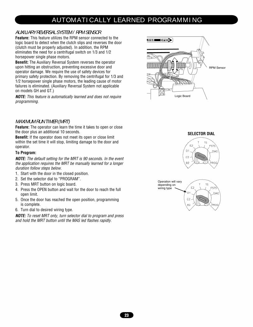
MAXIMUM RUN TIMER (MRT)Feature: The operator can learn the time it takes to open or close the door plus an additional 10 seconds.Benefit: If the operator does not meet its open or close limit within the set time it will stop, limiting damage to the door and operator.To Program:NOTE: The default setting for the MRT is 90 seconds. In the event the application requires the MRT be manually learned for a longer duration follow steps below.1. Start with the door in the closed position.2. Set the selector dial to “PROGRAM”.3. Press MRT button on logic board.4. Press the OPEN button and wait for the door to reach the full
open limit.5. Once the door has reached the open position, programming
is complete.6. Turn dial to desired wiring type.NOTE: To reset MRT only, turn selector dial to program and press and hold the MRT button until the MAS led flashes rapidly.
Operation will vary depending on wiring type
SELECTOR DIAL
AUXILIARY REVERSAL SYSTEM / RPM SENSORFeature: This feature utilizes the RPM sensor connected to the logic board to detect when the clutch slips and reverses the door (clutch must be properly adjusted). In addition, the RPM eliminates the need for a centrifugal switch on 1/3 and 1/2 horsepower single phase motors.Benefit: The Auxiliary Reversal System reverses the operator upon hitting an obstruction, preventing excessive door and operator damage. We require the use of safety devices for primary safety protection. By removing the centrifugal for 1/3 and 1/2 horsepower single phase motors, the leading cause of motor failures is eliminated. (Auxiliary Reversal System not applicable on models GH and GT.)NOTE: This feature is automatically learned and does not require programming.
LOSE OPEN
RPM Sensor
Logic Board
A U T O M A T I C A L L Y L E A R N E D P R O G R A M M I N G
24
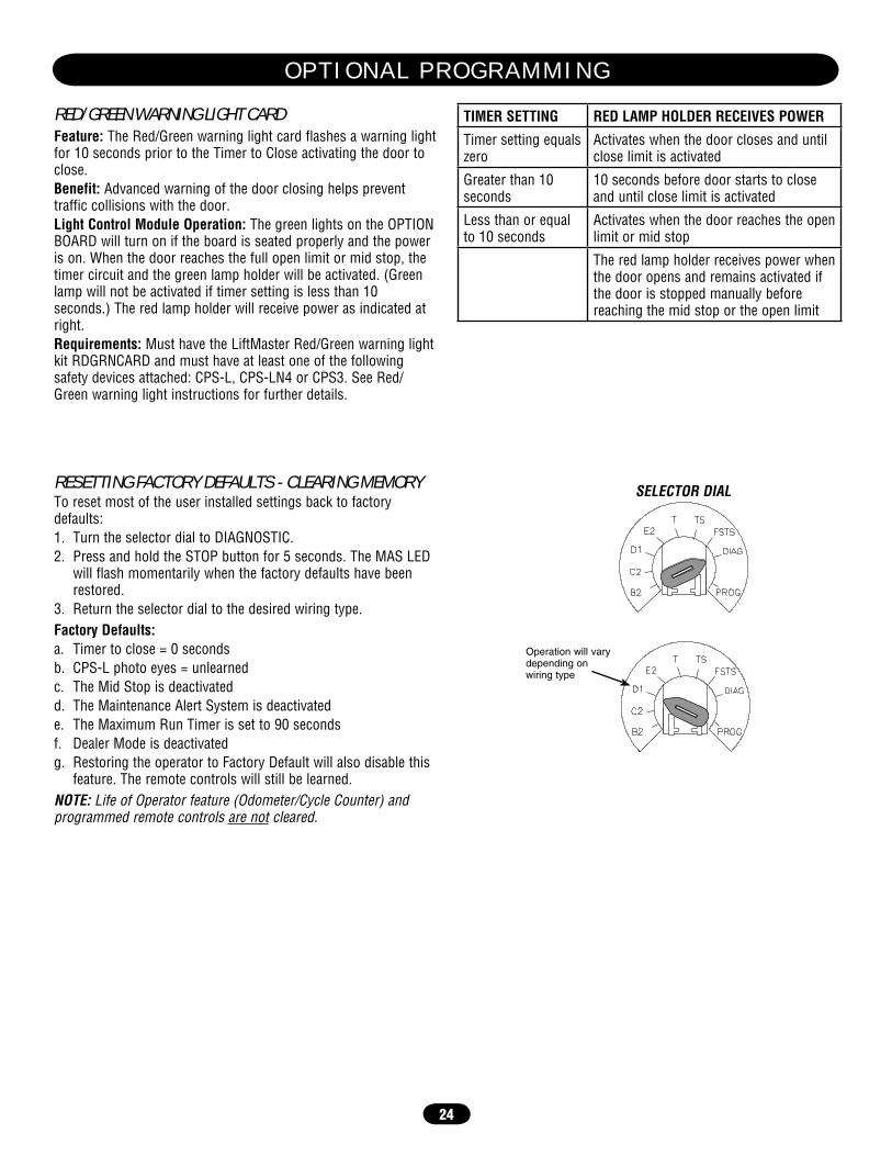
RESETTING FACTORY DEFAULTS - CLEARING MEMORYTo reset most of the user installed settings back to factory defaults:1. Turn the selector dial to DIAGNOSTIC.2. Press and hold the STOP button for 5 seconds. The MAS LED
will flash momentarily when the factory defaults have been restored.
3. Return the selector dial to the desired wiring type.Factory Defaults:a. Timer to close = 0 secondsb. CPS-L photo eyes = unlearnedc. The Mid Stop is deactivatedd. The Maintenance Alert System is deactivatede. The Maximum Run Timer is set to 90 secondsf. Dealer Mode is deactivatedg. Restoring the operator to Factory Default will also disable this
feature. The remote controls will still be learned.NOTE: Life of Operator feature (Odometer/Cycle Counter) and programmed remote controls are not cleared.
Operation will vary depending on wiring type
SELECTOR DIAL
RED/GREEN WARNING LIGHT CARDFeature: The Red/Green warning light card flashes a warning light for 10 seconds prior to the Timer to Close activating the door to close. Benefit: Advanced warning of the door closing helps prevent traffic collisions with the door.Light Control Module Operation: The green lights on the OPTION BOARD will turn on if the board is seated properly and the power is on. When the door reaches the full open limit or mid stop, the timer circuit and the green lamp holder will be activated. (Green lamp will not be activated if timer setting is less than 10 seconds.) The red lamp holder will receive power as indicated at right.Requirements: Must have the LiftMaster Red/Green warning light kit RDGRNCARD and must have at least one of the following safety devices attached: CPS-L, CPS-LN4 or CPS3. See Red/Green warning light instructions for further details.
TIMER SETTING RED LAMP HOLDER RECEIVES POWER
Timer setting equals zero
Activates when the door closes and until close limit is activated
Greater than 10 seconds
10 seconds before door starts to close and until close limit is activated
Less than or equal to 10 seconds
Activates when the door reaches the open limit or mid stop
The red lamp holder receives power when the door opens and remains activated if the door is stopped manually before reaching the mid stop or the open limit
O P T I O N A L P R O G R A M M I N G
25
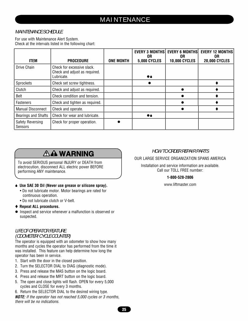
MAINTENANCE SCHEDULE
For use with Maintenance Alert System.Check at the intervals listed in the following chart:
HOW TO ORDER REPAIR PARTS
OUR LARGE SERVICE ORGANIZATION SPANS AMERICA
Installation and service information are available.Call our TOLL FREE number:
1-800-528-2806
www.liftmaster.com Use SAE 30 Oil (Never use grease or silicone spray).• Do not lubricate motor. Motor bearings are rated for
continuous operation.• Do not lubricate clutch or V-belt.
Repeat ALL procedures. Inspect and service whenever a malfunction is observed or suspected.
To avoid SERIOUS personal INJURY or DEATH from electrocution, disconnect ALL electric power BEFORE performing ANY maintenance.
ATTENTION
AVERTISSEMENT AVERTISSEMENT
AVERTISSEMENT
WARNING
CAUTION
WARNING
WARNING WARNING
PRECAUCIÓN ADVERTENCIA
ADVERTENCIA ADVERTENCIA
LIFE OF OPERATOR FEATURE(ODOMETER/CYCLE COUNTER)The operator is equipped with an odometer to show how many months and cycles the operator has performed from the time it was installed. This feature can help determine how long the operator has been in service.1. Start with the door in the closed position.2. Turn the SELECTOR DIAL to DIAG (diagnostic mode).3. Press and release the MAS button on the logic board.4. Press and release the MRT button on the logic board.5. The open and close lights will flash. OPEN for every 5,000
cycles and CLOSE for every 3 months.6. Return the SELECTOR DIAL to the desired wiring type.NOTE: If the operator has not reached 5,000 cycles or 3 months, there will be no indications.
ITEM PROCEDURE ONE MONTH
EVERY 3 MONTHS OR
5,000 CYCLES
EVERY 6 MONTHSOR
10,000 CYCLES
EVERY 12 MONTHS OR
20,000 CYCLES
Drive Chain Check for excessive slack.Check and adjust as required.Lubricate.
Sprockets Check set screw tightness.
Clutch Check and adjust as required.
Belt Check condition and tension.
Fasteners Check and tighten as required.
Manual Disconnect Check and operate.
Bearings and Shafts Check for wear and lubricate.
Safety Reversing Sensors
Check for proper operation.
M A I N T E N A N C E

26
DIAGNOSTIC CHARTThe logic board has several LEDs to assist in the installation and troubleshooting of the operator. The following chart should assist in verifying the operator is functioning properly. Turn the selector dial to DIAGNOSTIC to keep the door from moving while troubleshooting.
LED COLOR DEFINITION
Power Green Indicates that power is being generated for the logic board.
Stop Green Indicates a closed circuit between common and terminal 5. Pressing stop should turn off this LED.
Open Yellow Indicates a closed circuit between common and terminal 7. Pressing the open button should turn ON this LED.
Close Yellow Indicates a closed circuit between common and terminal 6. Pressing the close button should turn ON this LED.
Eyes Green Solid on indicates photo eyes learned. Flashing indicates photo eyes need to be connected or obstructed. Solid off indicates no eyes learned.
Timer Defeat Yellow Solid on indicates a closed circuit between common and terminal 12. Timer to close will not close.
OLS Yellow Pressing the Open Limit Switch should turn ON this LED.
CLS Yellow Pressing the Close Limit Switch should turn ON this LED.
SLS Yellow Pressing the Sensing Limit Switch should turn ON this LED.
Edge Yellow Indicates a closed circuit between common and terminal 8. Pressing the edge should turn ON this LED.
Mid Stop Yellow Solid on indicates door is stopped on up or down mid stop. Flashing indicates MID STOP is being set.
Timer Enabled Green Solid on indicates TIMER is programmed and will activate from open or mid stop position. Flashing indicates Timer is counting down and door will close after preset time.
SBC Yellow Indicates a closed circuit between common and terminal 1. Pressing the single button control station should turn ON this LED.
MAS Yellow Indicates the Maintenance Alert System has been activated or an error code has been triggered.
Relay A Yellow Indicates open or close command has been given to the motor. LED turns on when OPEN/CLOSE button is pressed.
Relay B Yellow Indicates open or close command has been given to the motor. LED turns on when OPEN/CLOSE button is pressed.
T R O U B L E S H O O T I N G
27
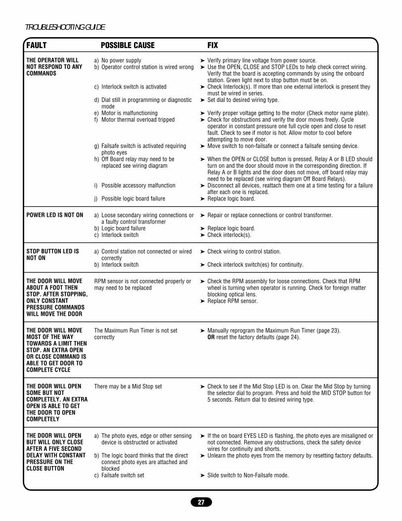
TROUBLESHOOTING GUIDE
FAULT POSSIBLE CAUSE FIX
THE OPERATOR WILL NOT RESPOND TO ANY COMMANDS
a) No power supplyb) Operator control station is wired wrong
c) Interlock switch is activated
d) Dial still in programming or diagnostic mode
e) Motor is malfunctioningf) Motor thermal overload tripped
g) Failsafe switch is activated requiring photo eyes
h) Off Board relay may need to be replaced see wiring diagram
i) Possible accessory malfunction
j) Possible logic board failure
➤ Verify primary line voltage from power source.➤ Use the OPEN, CLOSE and STOP LEDs to help check correct wiring.
Verify that the board is accepting commands by using the onboard station. Green light next to stop button must be on.
➤ Check Interlock(s). If more than one external interlock is present they must be wired in series.
➤ Set dial to desired wiring type.
➤ Verify proper voltage getting to the motor (Check motor name plate).➤ Check for obstructions and verify the door moves freely. Cycle
operator in constant pressure one full cycle open and close to reset fault. Check to see if motor is hot. Allow motor to cool before attempting to move door.
➤ Move switch to non-failsafe or connect a failsafe sensing device.
➤ When the OPEN or CLOSE button is pressed, Relay A or B LED should turn on and the door should move in the corresponding direction. If Relay A or B lights and the door does not move, off board relay may need to be replaced (see wiring diagram Off Board Relays).
➤ Disconnect all devices, reattach them one at a time testing for a failure after each one is replaced.
➤ Replace logic board.
POWER LED IS NOT ON a) Loose secondary wiring connections or a faulty control transformer
b) Logic board failurec) Interlock switch
➤ Repair or replace connections or control transformer.
➤ Replace logic board.➤ Check interlock(s).
STOP BUTTON LED IS NOT ON
a) Control station not connected or wired correctly
b) Interlock switch
➤ Check wiring to control station.
➤ Check interlock switch(es) for continuity.
THE DOOR WILL MOVE ABOUT A FOOT THEN STOP. AFTER STOPPING, ONLY CONSTANT PRESSURE COMMANDS WILL MOVE THE DOOR
RPM sensor is not connected properly or may need to be replaced
➤ Check the RPM assembly for loose connections. Check that RPM wheel is turning when operator is running. Check for foreign matter blocking optical lens.
➤ Replace RPM sensor.
THE DOOR WILL MOVE MOST OF THE WAY TOWARDS A LIMIT THEN STOP. AN EXTRA OPEN OR CLOSE COMMAND IS ABLE TO GET DOOR TO COMPLETE CYCLE
The Maximum Run Timer is not set correctly
➤ Manually reprogram the Maximum Run Timer (page 23).OR reset the factory defaults (page 24).
THE DOOR WILL OPEN SOME BUT NOT COMPLETELY. AN EXTRA OPEN IS ABLE TO GET THE DOOR TO OPEN COMPLETELY
There may be a Mid Stop set ➤ Check to see if the Mid Stop LED is on. Clear the Mid Stop by turning the selector dial to program. Press and hold the MID STOP button for 5 seconds. Return dial to desired wiring type.
THE DOOR WILL OPEN BUT WILL ONLY CLOSE AFTER A FIVE SECOND DELAY WITH CONSTANT PRESSURE ON THE CLOSE BUTTON
a) The photo eyes, edge or other sensing device is obstructed or activated
b) The logic board thinks that the direct connect photo eyes are attached and blocked
c) Failsafe switch set
➤ If the on board EYES LED is flashing, the photo eyes are misaligned or not connected. Remove any obstructions, check the safety device wires for continuity and shorts.
➤ Unlearn the photo eyes from the memory by resetting factory defaults.
➤ Slide switch to Non-Failsafe mode.

28
TROUBLESHOOTING ERROR CODESLogic 3.0 operators incorporate a self diagnostic feature built into the MAS LED. In addition to indicating when routing maintenance is due, the MAS LED can be used to troubleshoot some problems with the operator.If the MAS LED is flashing on and off rapidly, the Maintenance Alert System has been triggered and the schedule operator service is due. If the MAS LED flashes 2 or more pulses in a row
ERROR CODE DESCRIPTION EFFECT DISPLAY CORRECTION
E1 MAS triggered (cycles or months).
None normal operation. 1 blink Reset MAS.
E2 No RPM input during opening or closing.
The door only responds to constant pressure commands.
2 blinks Clutch is slipping, adjust clutch, or verify RPM sensor connection or replace RPM sensor. NOTE: To relearn the RPM sensor, move the door with a constant pressure command. The door will stop once relearned and normal operation will resume.
E3 (MRT) Maximum Run Time timed out.
The door stops before reaching the desired time.
3 blinks First check Operator for any faults (i.e., Bad Limit switch), manually learn Max Run Timer (page 23) OR reset factory defaults (page 24).
E4 Obstruction sensed on closing.
Operator will be in the OPEN position.
4 blinks Cleared by removing obstruction or realigning photo eyes and giving a close command.
E5 Stuck key button pressed for greater than 2 minutes.
Stuck key on 3-button station will not respond.
5 blinks Stuck key must be unstuck before it will be recognized as an input.
E6 Rotary dial in invalid position for greater than 30 seconds.
The door will not respond to the 3-button station or any other input.
6 blinks Rotary dial must be set to a valid position.
E7 Failsafe Safety device faulted or not connected for greater than 2 minutes.
Normal operation (5 second constant pressure override required to close).
7 blinks Cleared when safety device is cleared or connected.
E8 Brownout Detected. Operator will run as long as enough power is present.
8 blinks 1. Check AC line for voltage.2. Check transformer secondary for low
voltage. To many accessories may be connected to the transformer.
E9 Motor movement at invalid time.
Operator will continue to function normally for 5 operations and then default to a constant pressure mode.
Flash on start of movement
Check relays and the drive circuitry to insure that they are turning off. Operator must run correctly for two starts for the error to be cleared.
followed by a pause, an operator error has occurred. To view how many errors currently exist, turn the selector dial to DIAGNOSTIC and press the OPEN button. To read out each individual error code (if more than one exists) press CLOSE. It is possible to have more than one error at a time.The chart below can assist with identifying the flashes on the MAS LED.
NOTES: Error codes take priority over normal MAS LED operation. Error codes will repeat on the MAS every 1.5 seconds until cleared. There may be more than one error present, but only the highest priority will flash. If the highest error is cleared, the next highest will flash. All errors self-correct when the corrective action is taken and a reset is not needed.
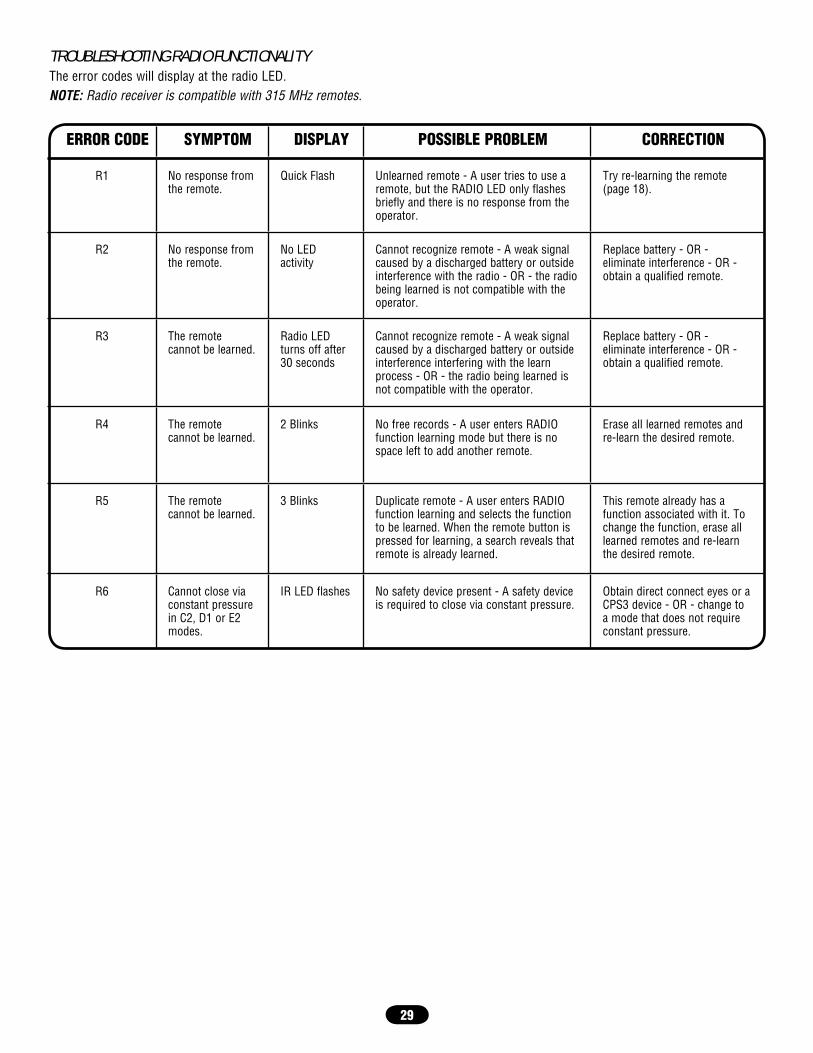
29
TROUBLESHOOTING RADIO FUNCTIONALITYThe error codes will display at the radio LED.NOTE: Radio receiver is compatible with 315 MHz remotes.
ERROR CODE SYMPTOM DISPLAY POSSIBLE PROBLEM CORRECTION
R1 No response from the remote.
Quick Flash Unlearned remote - A user tries to use a remote, but the RADIO LED only flashes briefly and there is no response from the operator.
Try re-learning the remote (page 18).
R2 No response from the remote.
No LED activity
Cannot recognize remote - A weak signal caused by a discharged battery or outside interference with the radio - OR - the radio being learned is not compatible with the operator.
Replace battery - OR -eliminate interference - OR - obtain a qualified remote.
R3 The remote cannot be learned.
Radio LED turns off after 30 seconds
Cannot recognize remote - A weak signal caused by a discharged battery or outside interference interfering with the learn process - OR - the radio being learned is not compatible with the operator.
Replace battery - OR - eliminate interference - OR - obtain a qualified remote.
R4 The remote cannot be learned.
2 Blinks No free records - A user enters RADIO function learning mode but there is no space left to add another remote.
Erase all learned remotes and re-learn the desired remote.
R5 The remote cannot be learned.
3 Blinks Duplicate remote - A user enters RADIO function learning and selects the function to be learned. When the remote button is pressed for learning, a search reveals that remote is already learned.
This remote already has a function associated with it. To change the function, erase all learned remotes and re-learn the desired remote.
R6 Cannot close via constant pressure in C2, D1 or E2 modes.
IR LED flashes No safety device present - A safety device is required to close via constant pressure.
Obtain direct connect eyes or a CPS3 device - OR - change to a mode that does not require constant pressure.

30
6
9
8
1
4
7
5
2
11
10
3
K1
K2
(K72-10047-1)
(K72-12515-1)
(K72-10047)
E L E C T R I C A L B O X

31
For replacement of electrical box, motor or brake components be sure to match model number of your unit to kit number below to ensure proper voltage requirements.
SERVICE KITS
ITEM PART # DESCRIPTIONK1 K72-10047 Limit shaft kit (1/2 up to 2HP)
K72-10047-1 Limit shaft kit (3HP)Complete with: Limit shaft, limit nuts, limit bearings, limit sprocket, interrupter cup, shim washers, compression ring, roll pin, and e-rings.
K2 K72-12515-1 Limit switch kitComplete with: Limit nut retainer, switch plates, backup plate, depress plates, limit switches, standoffs, screws, and locknuts.
* To order a complete electrical box kit, add a K- prefix to the model number of your operator. For example: GH5011L3 (Operator) = K-GH5011L3 (Electrical box kit)
INDIVIDUAL PARTS
ITEM PART # DESCRIPTION 1 13-10024 Limit nut 2 23-10041 Limit switch3 K75-32268 Cover 4 21-14182 Transformer, 115/230V 21-35057 Transformer, 460V
21-5575 Transformer, 575V5 29-31244 Relay 24Vdc DPST - (A and B relay)
all operators6 29-31245 Relay 12Vdc SPDT - (C and D relay)
3 Phase only 29-31229 Relay 24Vdc SPDT - (C relay)
1 Phase only7 K74-31243 MOV 580V 8 K79-15016-1 RPM sensor assembly9 K1A5729 Logic board - Logic 3 10 K2A761 Coaxial cable11 K1C3196-3 Antenna
*Non stocked item. Please allow additional delivery time.
E L E C T R I C A L B O X L O G I C ( V E R 3 . 0 )
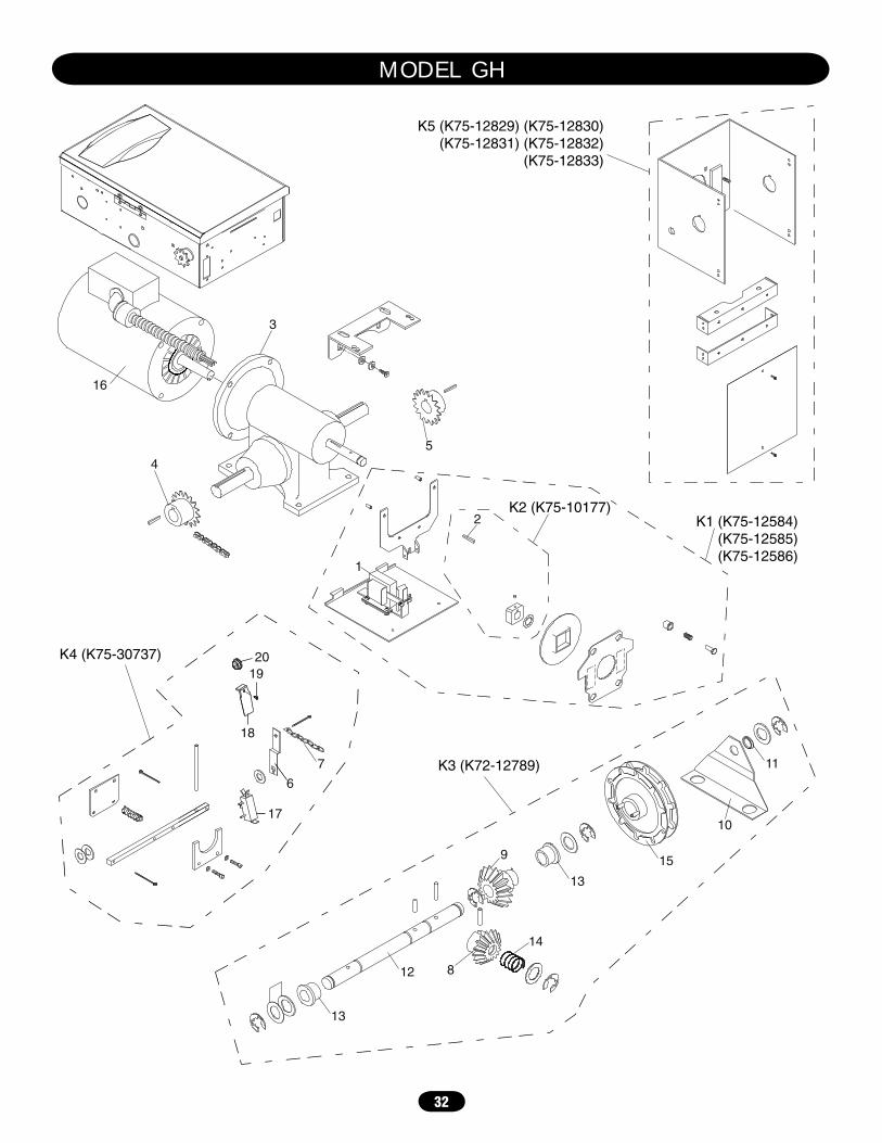
32
1
3
4
K5 (K75-12829) (K75-12830)(K75-12831) (K75-12832)
(K75-12833)
K1 (K75-12584)(K75-12585)(K75-12586)
2
5
K4 (K75-30737)
6
17
18
1920
7 K3 (K72-12789)
13
13
8
9
10
11
12
14
15
16
K2 (K75-10177)
M O D E L G H
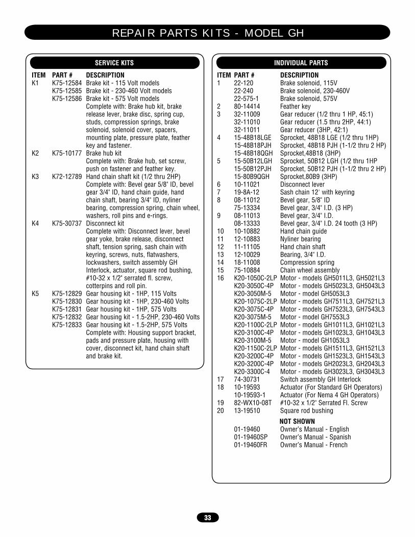
33
SERVICE KITS
ITEM PART # DESCRIPTIONK1 K75-12584 Brake kit - 115 Volt models
K75-12585 Brake kit - 230-460 Volt modelsK75-12586 Brake kit - 575 Volt models
Complete with: Brake hub kit, brake release lever, brake disc, spring cup, studs, compression springs, brake solenoid, solenoid cover, spacers, mounting plate, pressure plate, feather key and fastener.
K2 K75-10177 Brake hub kitComplete with: Brake hub, set screw, push on fastener and feather key.
K3 K72-12789 Hand chain shaft kit (1/2 thru 2HP)Complete with: Bevel gear 5/8" ID, bevel gear 3/4" ID, hand chain guide, hand chain shaft, bearing 3/4" ID, nyliner bearing, compression spring, chain wheel, washers, roll pins and e-rings.
K4 K75-30737 Disconnect kitComplete with: Disconnect lever, bevel gear yoke, brake release, disconnect shaft, tension spring, sash chain with keyring, screws, nuts, flatwashers, lockwashers, switch assembly GH Interlock, actuator, square rod bushing, #10-32 x 1/2" serrated fl. screw, cotterpins and roll pin.
K5 K75-12829 Gear housing kit - 1HP, 115 VoltsK75-12830 Gear housing kit - 1HP, 230-460 VoltsK75-12831 Gear housing kit - 1HP, 575 VoltsK75-12832 Gear housing kit - 1.5-2HP, 230-460 VoltsK75-12833 Gear housing kit - 1.5-2HP, 575 Volts
Complete with: Housing support bracket, pads and pressure plate, housing with cover, disconnect kit, hand chain shaft and brake kit.
INDIVIDUAL PARTS
ITEM PART # DESCRIPTION1 22-120 Brake solenoid, 115V
22-240 Brake solenoid, 230-460V22-575-1 Brake solenoid, 575V
2 80-14414 Feather key3 32-11009 Gear reducer (1/2 thru 1 HP, 45:1) 32-11010 Gear reducer (1.5 thru 2HP, 44:1) 32-11011 Gear reducer (3HP, 42:1)4 15-48B18LGE Sprocket, 48B18 LGE (1/2 thru 1HP) 15-48B18PJH Sprocket, 48B18 PJH (1-1/2 thru 2 HP) 15-48B18QGH Sprocket,48B18 (3HP)5 15-50B12LGH Sprocket, 50B12 LGH (1/2 thru 1HP 15-50B12PJH Sprocket, 50B12 PJH (1-1/2 thru 2 HP) 15-80B9QGH Sprocket,80B9 (3HP)6 10-11021 Disconnect lever7 19-8A-12 Sash chain 12' with keyring8 08-11012 Bevel gear, 5/8" ID 75-13334 Bevel gear, 3/4" I.D. (3 HP)9 08-11013 Bevel gear, 3/4" I.D. 08-13333 Bevel gear, 3/4" I.D. 24 tooth (3 HP)10 10-10882 Hand chain guide11 12-10883 Nyliner bearing12 11-11105 Hand chain shaft13 12-10029 Bearing, 3/4" I.D.14 18-11008 Compression spring15 75-10884 Chain wheel assembly16 K20-1050C-2LP Motor - models GH5011L3, GH5021L3
K20-3050C-4P Motor - models GH5023L3, GH5043L3K20-3050M-5 Motor - model GH5053L3K20-1075C-2LP Motor - models GH7511L3, GH7521L3K20-3075C-4P Motor - models GH7523L3, GH7543L3K20-3075M-5 Motor - model GH7553L3K20-1100C-2LP Motor - models GH1011L3, GH1021L3K20-3100C-4P Motor - models GH1023L3, GH1043L3K20-3100M-5 Motor - model GH1053L3K20-1150C-2LP Motor - models GH1511L3, GH1521L3K20-3200C-4P Motor - models GH1523L3, GH1543L3K20-3200C-4P Motor - models GH2023L3, GH2043L3K20-3300C-4 Motor - models GH3023L3, GH3043L3
17 74-30731 Switch assembly GH Interlock18 10-19593 Actuator (For Standard GH Operators) 10-19593-1 Actuator (For Nema 4 GH Operators)19 82-WX10-08T #10-32 x 1/2" Serrated Fl. Screw20 13-19510 Square rod bushing
NOT SHOWN 01-19460 Owner’s Manual - English 01-19460SP Owner’s Manual - Spanish 01-19460FR Owner’s Manual - French
R E P A I R P A R T S K I T S - M O D E L G H

34
O P E R A T O R N O T E S

35
O P E R A T O R N O T E S
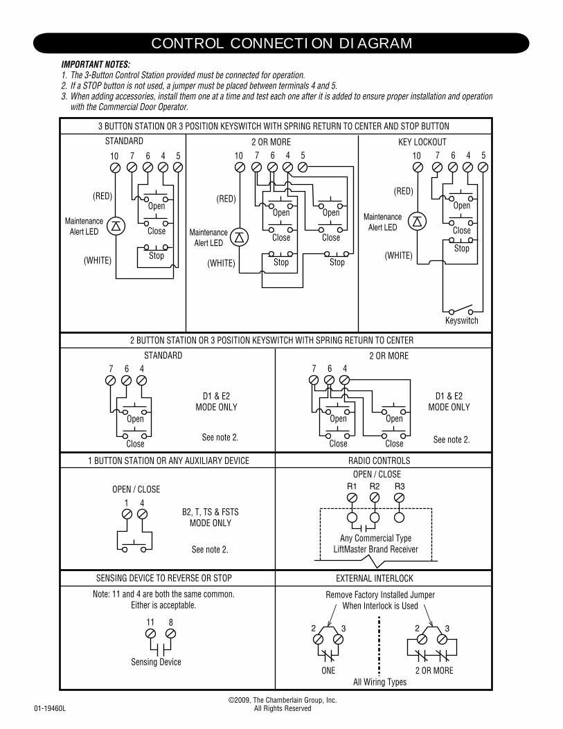
C O N T R O L C O N N E C T I O N D I A G R A MIMPORTANT NOTES:1. The 3-Button Control Station provided must be connected for operation.2. If a STOP button is not used, a jumper must be placed between terminals 4 and 5.3. When adding accessories, install them one at a time and test each one after it is added to ensure proper installation and operation with the Commercial Door Operator.
OPEN / CLOSE
3 BUTTON STATION OR 3 POSITION KEYSWITCH WITH SPRING RETURN TO CENTER AND STOP BUTTON
2 OR MORE KEY LOCKOUT
R1 R2 R3
7 6 4 5
Stop
Close
Open
Stop
Close
Open
7 6 4 5
Stop
Close
Open
2 BUTTON STATION OR 3 POSITION KEYSWITCH WITH SPRING RETURN TO CENTER
STANDARD7 6 4
Close
Open
D1 & E2MODE ONLY
2 OR MORE7 6 4
Close
Open
Close
Open
D1 & E2MODE ONLY
OPEN / CLOSE1 4
B2, T, TS & FSTSMODE ONLY
Any Commercial TypeLiftMaster Brand Receiver
1 BUTTON STATION OR ANY AUXILIARY DEVICE RADIO CONTROLS
SENSING DEVICE TO REVERSE OR STOP EXTERNAL INTERLOCK
11 82 3 2 3
Remove Factory Installed JumperWhen Interlock is Used
ONE 2 OR MORE
STANDARD
7 6 4 5
Stop
Close
Open
All Wiring Types
Keyswitch
Sensing Device
10
MaintenanceAlert LED
10 10
MaintenanceAlert LED
MaintenanceAlert LED
(RED)
(WHITE)
(RED)
(WHITE)
(RED)
(WHITE)
Note: 11 and 4 are both the same common.Either is acceptable.
See note 2.
See note 2.See note 2.
©2009, The Chamberlain Group, Inc.01-19460L All Rights Reserved