industrial ethernet - cni.co.th ethernet.pdf · industrial ethernet ... the data field contains 46...
TRANSCRIPT

110 Theoretical and general applications www.westermo.com
Industrial Ethernet
As a communication standard, Ethernet has existed for many years and today formsthe basis of most networks throughout the world. Despite many claims over the yearsthat Ethernet will be replaced, it continues to be developed and offers the propertiesthat users have requested. In recent years Ethernet has also won approval in the indus-trial market.
IEEE 802.3 Ethernet
Access methodsIn order for two or more parties to communicate requires a set of rules, this applies toeverything, especially to data communication. How data is transmitted on to a line isknown as the access method, the original method used by Ethernet was calledCSMA/CD, which means: Carrier Sense Multiple Access/Collision Detect. It is impor-tant to establish that Ethernet uses two access methods, constant access orCSMA/CD. CSMA/CD is referred to regularly in literature but is not so commonlyused today. It has a historical background and for this reason we will give a briefdescription of the parts in CSMA/CD:
… Carrier Sense, which means that a single unit, before it sends, must detectwhether someone is using the network. If so, the unit must wait before it trans-mits.
… Multiple Access, means that everyone can use the network, but not simultane-ously.
… Collision Detect, means that when two or more units transmit simultaneouslythis should be detected. When a collision is detected, a collision signal is sentand all those concerned stop sending. All units then wait for a random periodbefore new attempts are made, this minimises the risk of them starting to sendat the same time. Naturally, collisions have the effect of slowing traffic in the sys-tem. A network with a high load results in many collisions, which leads to fur-ther network traffic, which in turn creates more collisions, etc. Some equipmenthas LEDs that indicate collisions, in doing so you can easily check the load onthe network. The advantage of a CSMA/CD network is that all equipment canstart transmitting at any time compared with a polled system or token ringwhere transmission is strictly controlled.
CSMA/CD
CSMA/CD
CSMA/CD

www.westermo.com Theoretical and general applications 111
Ethernet Address & PacketsAll Ethernet hardware has an address that uniquely identifies each node in a network.This address is programmed into the device by the manufacturer, for example, a net-work adapter card. This can not be changed by the user or by software, which meansthere is not (should not be) two network adapter cards with the same address. Thisaddress is often refered to as the MAC Media Access Control Address.
The Ethernet packet contains the following information:… Preamble. The preamble is a 64-bit (8 byte) field that contains a synchroniza-
tion pattern consisting of alternating ones and zeros and ending with two con-secutive ones. After synchronization is established, the preamble is used tolocate the first bit of the packet. The preamble is generated by the LAN inter-face card.
… Destination Address. The destination address field is a 48-bit (6 byte) field thatspecifies the station or stations to which the packet should be sent. Each stationexamines this field to determine whether it should accept the packet.
… Source Address. The source address field is a 48-bit (6 byte) field that containsthe unique address of the station that is transmitting the packet.
… Type field. The type field is 16-bit (2 byte) field that identifies the higher-levelprotocol associated with the packet. It is interpreted at the data link level.
… Data Field. The data field contains 46 to 1500 bytes. Each octet (8-bit field)contains any arbitrary sequence of values. The data field is the informationreceived from Layer 3 (Network Layer). The information, or packet, receivedfrom Layer 3 is broken into frames of information of 46 to 1500 bytes byLayer 2.
… CRC Field. The Cyclic Redundancy Check (CRC) field is a 32-bit error check-ing field. The CRC is generated based on the destination address, type and datafields.
Preamable Destination address Source address Type Data CRC8 bytes 6 bytes 6 bytes 2 bytes 46 – 1500 bytes 4 bytes
112 Theoretical and general applications www.westermo.com
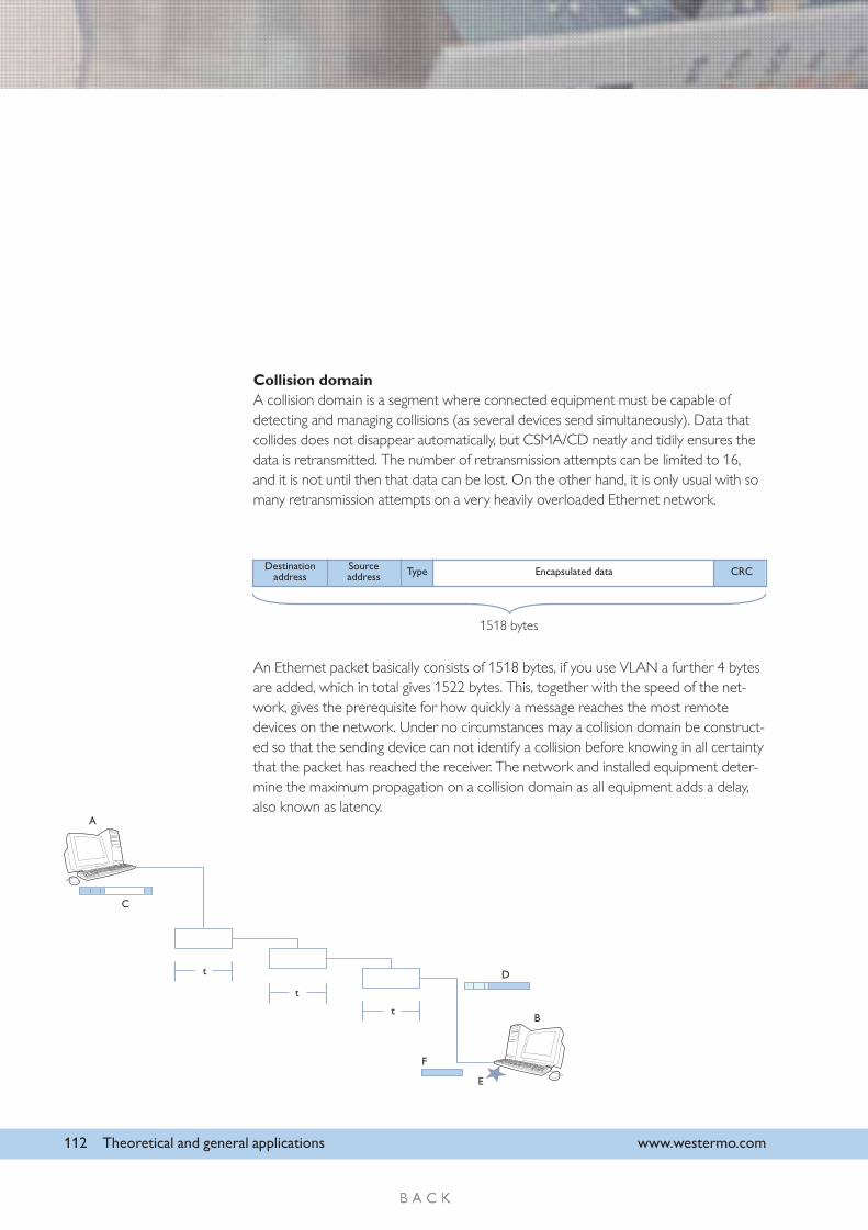
Collision domainA collision domain is a segment where connected equipment must be capable ofdetecting and managing collisions (as several devices send simultaneously). Data thatcollides does not disappear automatically, but CSMA/CD neatly and tidily ensures thedata is retransmitted. The number of retransmission attempts can be limited to 16,and it is not until then that data can be lost. On the other hand, it is only usual with somany retransmission attempts on a very heavily overloaded Ethernet network.
An Ethernet packet basically consists of 1518 bytes, if you use VLAN a further 4 bytesare added, which in total gives 1522 bytes. This, together with the speed of the net-work, gives the prerequisite for how quickly a message reaches the most remotedevices on the network. Under no circumstances may a collision domain be construct-ed so that the sending device can not identify a collision before knowing in all certaintythat the packet has reached the receiver. The network and installed equipment deter-mine the maximum propagation on a collision domain as all equipment adds a delay,also known as latency.
Destinationaddress
Sourceaddress Type Encapsulated data
1518 bytes
A
C
t
t
t
D
B
F
E
CRC

www.westermo.com Theoretical and general applications 113
… Assume that A intends to send a packet to B.… The network includes a certain amount of equipment that has an internal
delay (t).… A continuously empties its send buffer, when no collision is discovered.… A collision occurs on the outermost node on the network (E).… All data (D) is not received, which results in (B) not being able to interpret it.… The collision signal (F) is sent back to the transmitter (A).… When the domain is too large, the collision signal does not reach (A) before the
send buffer has been emptied. This makes it impossible to retransmit the packet.
IP Networks
Internet ProtocolIP or Internet Protocol is designed for connections in a network or between severalnetworks. When the specification was written it was understood that new technolo-gies and new transfer methods would be continuously developed. This is why an openstandard that is primarily independent of the underlying network and medium wasdeveloped. TCP/IP is a family of protocols that extends between many different layersin the OSI-model.
Addressing methodsMuch of the information in a network goes from single sender to a single receiver. Thisis completely natural in most cases, for example, a PLC communicating with an I/Odevice. This kind of transfer is usually called unicast.
The opposite to unicast is “broadcast”, i.e. the way that radio and television are trans-mitted: one sender and many receivers. Broadcasting means that information is sentout to everyone, the technique is used in some closed computer networks, but broad-casting over the entire Internet is impossible as it would overload the network.
Multicast is a technique that fits in between unicast and broadcast. Information is notsent out indiscriminately to everyone as in broadcasting, but the same information canhave numerous receivers unlike unicasting. Using multicast allows the building of distri-bution networks, which are suitable for video monitoring or television transmissionsover the Internet, i.e. information with one sender and many receivers. Multicast willopen up new possibilities for the Internet and prevent it from collapsing due to over-loading.
Network
Network
Network
Unicast
Broadcast
Multicast
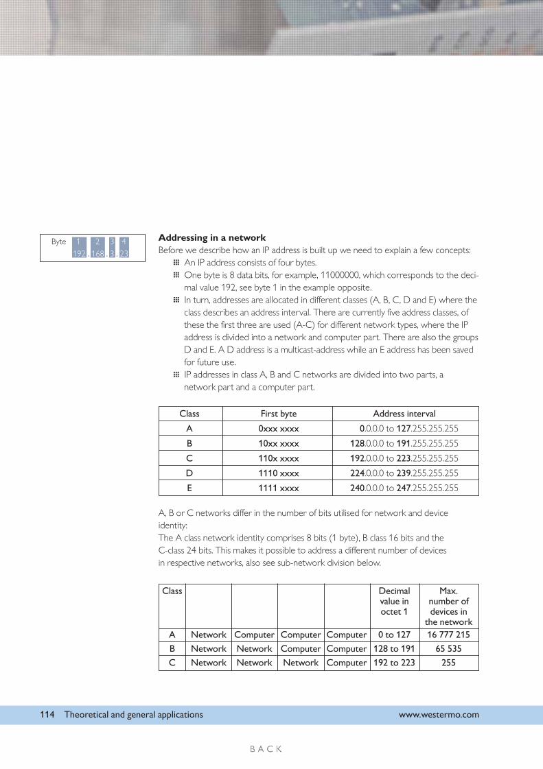
Class Decimal Max.value in number ofoctet 1 devices in
the networkA Network Computer Computer Computer 0 to 127 16 777 215
B Network Network Computer Computer 128 to 191 65 535
C Network Network Network Computer 192 to 223 255
114 Theoretical and general applications www.westermo.com
Addressing in a networkBefore we describe how an IP address is built up we need to explain a few concepts:
… An IP address consists of four bytes.… One byte is 8 data bits, for example, 11000000, which corresponds to the deci-
mal value 192, see byte 1 in the example opposite.… In turn, addresses are allocated in different classes (A, B, C, D and E) where the
class describes an address interval. There are currently five address classes, ofthese the first three are used (A-C) for different network types, where the IPaddress is divided into a network and computer part. There are also the groupsD and E. A D address is a multicast-address while an E address has been savedfor future use.
… IP addresses in class A, B and C networks are divided into two parts, anetwork part and a computer part.
A, B or C networks differ in the number of bits utilised for network and deviceidentity:The A class network identity comprises 8 bits (1 byte), B class 16 bits and theC-class 24 bits. This makes it possible to address a different number of devicesin respective networks, also see sub-network division below.
Class First byte Address interval
A 0xxx xxxx 0.0.0.0 to 127.255.255.255
B 10xx xxxx 128.0.0.0 to 191.255.255.255
C 110x xxxx 192.0.0.0 to 223.255.255.255
D 1110 xxxx 224.0.0.0 to 239.255.255.255
E 1111 xxxx 240.0.0.0 to 247.255.255.255
Byte 1 2 3 4
192 . 168 . 3 . 23

www.westermo.com Theoretical and general applications 115
Private and public addressesThere may be cases where you can not use or do not want to use public IP addresseson your internal network, instead you can use private IP addresses (RFC1918). TheseIP addresses will not work on an Internet connection, the solution is then to use NAT(Network Address Translation).
Internal networkwith private IP addresses
Routerwith NAT
10.0.1.1 10.0.1.2 10.0.1.3
10.01.4 60.20.10.10
Internet
A router or “firewall” with support for NAT translates private addresses to publicaddresses:When the computer with address 10.0.1.2 needs to access the Internet, 10.0.1.4 isaddressed which is the “Default Gateway” or “way out”. When data from address10.0.1.2 passes through the router NAT translates the internal IP address 10.0.1.2 to60.20.10.10 i.e. the IP address on the “outside”. In this way an internal IP address cancommunicate with other computers on the Internet. It does not matter when anotherinternal IP address communicates at the same time as the router manages which ses-sion belongs to which internal IP address and ensures the right traffic goes to the rightcomputer on the internal network.
IANA (Internet Assigned Numbers Authority) has reserved the following threeaddress blocks for IP addresses in private networks:10.0.0.0 - 10.255.255.255172.16.0.0 - 172.31.255.255192.168.0.0 - 192.168.255.255

116 Theoretical and general applications www.westermo.com
Ipv4 and Ipv6IPv6 is version 6 of the Internet-protocol, the new version was drawn up at the end ofthe 1990s to replace the current, IPv4 (version 4), mainly because the IP addresses arestarting to come to an end. The greatest difference between IPv6 and IPv4 is that theaddress length has been increased from 32 bits to 128 bits. This means the number ofpossible addresses has been increased from 4 billion to a real astronomical number.
Ipv6 header
Subnetwork divisionLocal networks with more than a few hundred connected devices are unusual; allow-ing this kind of network to take up its own A or B Class (Over 16 million networkswith 65000 devices possible on each network) is an immense waste of availableaddresses. Most of these classes are therefore divided into a subnetwork, where apart of the device identity is used as a type of network address. The division is madeby utilising a part of the device identity, i.e. the “border” between the network addressand the device identity is “moved” so that the number of available network identities isincreased, at the same time as the number of devices in the subnetwork decreases. Inorder to achieve this a netmask is used where the bits that belong to the networkpart are set to one (and the computer bits are set to zero).
Smaller networks are easier to administrate, the data traffic in the subnetwork is less,the physical network becomes easier to set up and maintain (for example, you canutilise different subnetworks on different floors of a building), etc.
128 bits source address
Payload length Next header Hop limit
128 bits source address
128 bits destination address
www.westermo.com Theoretical and general applications 117
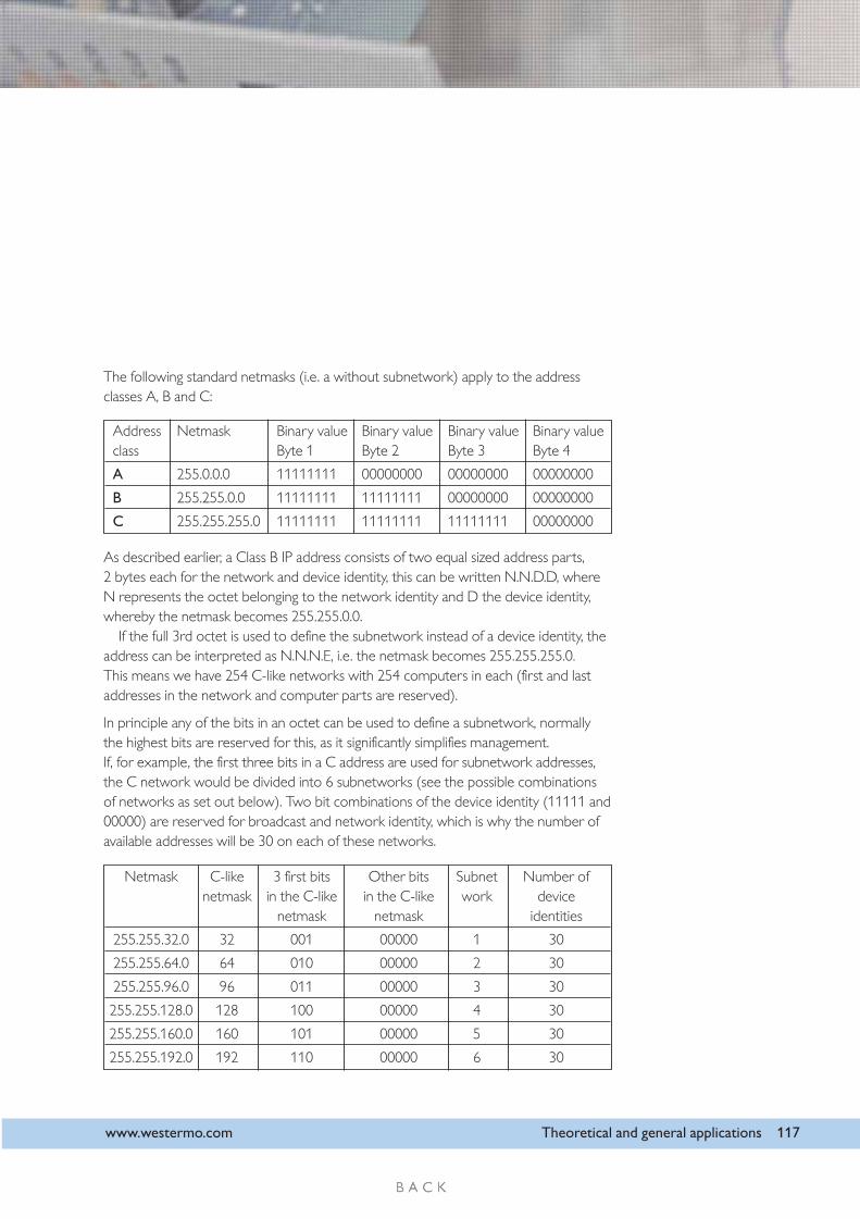
The following standard netmasks (i.e. a without subnetwork) apply to the addressclasses A, B and C:
As described earlier, a Class B IP address consists of two equal sized address parts,2 bytes each for the network and device identity, this can be written N.N.D.D, whereN represents the octet belonging to the network identity and D the device identity,whereby the netmask becomes 255.255.0.0.
If the full 3rd octet is used to define the subnetwork instead of a device identity, theaddress can be interpreted as N.N.N.E, i.e. the netmask becomes 255.255.255.0.This means we have 254 C-like networks with 254 computers in each (first and lastaddresses in the network and computer parts are reserved).
In principle any of the bits in an octet can be used to define a subnetwork, normallythe highest bits are reserved for this, as it significantly simplifies management.If, for example, the first three bits in a C address are used for subnetwork addresses,the C network would be divided into 6 subnetworks (see the possible combinationsof networks as set out below). Two bit combinations of the device identity (11111 and00000) are reserved for broadcast and network identity, which is why the number ofavailable addresses will be 30 on each of these networks.
Address Netmask Binary value Binary value Binary value Binary valueclass Byte 1 Byte 2 Byte 3 Byte 4
A 255.0.0.0 11111111 00000000 00000000 00000000
B 255.255.0.0 11111111 11111111 00000000 00000000
C 255.255.255.0 11111111 11111111 11111111 00000000
Netmask C-like 3 first bits Other bits Subnet Number ofnetmask in the C-like in the C-like work device
netmask netmask identities
255.255.32.0 32 001 00000 1 30
255.255.64.0 64 010 00000 2 30
255.255.96.0 96 011 00000 3 30
255.255.128.0 128 100 00000 4 30
255.255.160.0 160 101 00000 5 30
255.255.192.0 192 110 00000 6 30

118 Theoretical and general applications www.westermo.com
PortsAn application receives data on a special port number that identifies communicationwith this application.
For example, a computer can be both a web server, E-mail server and DNS serverrunning at the same time. In order for the traffic to the different applications not tocollide, it must be divided up, this is done by predefining the port number to the appli-cation. Port numbers between 1 and 1024 are known port numbers and must not beused by applications other than those specified.
Examples of known port numbers are:
21 ftp File transfer23 Telnet Telnet25 smtp Mail, Simple Mail transfer80 http www
A complete list can be found at www.iana.org/assignments/port-numbers
ARPComputers, or other hardware, that are connected to a TCP/IP–network all have atleast one IP address. The IP address is also known as the logical address as it is usuallyimplemented in software and can be changed depending on where in the network thehardware is physically located. The devices also have a physical address which in anEthernet network is called the MAC-address, this is unique for each piece of connect-ed hardware.
When two pieces of equipment (A) and (B) utilises TCP/IP to communicate overEthernet, they must keep track of each other’s MAC-address, as all communication onan Ethernet is made to MAC-addresses.
A
B
C
LAN
Sub net

www.westermo.com Theoretical and general applications 119
This is why devices A and B have their own ARP-table of IP addresses and associatedMAC-addresses.ARP Address Resolution Protocol, manages a dynamic update of the ARP-tables sothat the association between IP and MAC-addresses is always known.
… Assume that computer (A) wants to communicate with the PLC (B).Computer (A) already knows (B’s) IP address (can e.g. have been manually con-figured by an operator) but (B’s) MAC address is unknown to (A).Communication can not begin until (A) knows (B’s) MAC-address.
… A discovers that B is on the same network by comparing the destination’s IPaddress and the network mask.
… A sends out an ARP request in the form of a broadcast message. The enquirycontains (A’s) IP and MAC address as well as B’s IP address.
… All units on the network understand the message, but only B recognises its IPaddress and sends an ARP reply in response, which contains B’s MAC-address.
… A’s ARP-table can now be updated so that it also contains B’s MAC-address.
Point to Point (PPP)There are also occasions when you need to connect and communicate using TCP/IPvia a serial connection. This concerns connections to the Internet via a modem orwhen you need to connect to a local area network. How you communicate variesfrom application to application. On these occasions you use the PPP protocol(Point to Point Protocol.) which is without doubt the most used link protocol for com-puters that remotely connect to a network. Examples of serial communications are:telecom modem, modem with own leased line, ISDN, GSM, radio or short-haulmodems.
Security (CHAP and PAP)The protocol PPP is frequently used for remote point to point connections, irrespec-tive of whether it is a dial-up, ISDN or leased line. In general some form of securitybetween the communicating parties is required. PPP supports two methods of userverification, PAP (Password Authentication Protocol) and CHAP (ChallengeHandshake Authentication Protocol) for this purpose. Authentication, verification ofmessages, is not compulsory in PPP, so the parties are free to communicate withoutidentification or negotiating on which protocol to use. The principal rule is first andforemost to choose CHAP. PAP is generally only chosen when one of the parties doesnot support CHAP.

120 Theoretical and general applications www.westermo.com
PAP works similarly to when a user logs in using a terminal, you state your user nameand password. Authentication only takes place once when the connection is beingestablished, never while communication is in progress.
… The PAP-procedure starts by one of the parties sending an Authenticate-Request, containing name and password. This packet is repeated until theopposite party responds.
… When the name and password are accepted the recipient answers with anAuthenticate-Ack. Otherwise an Authenticate-Nak is sent as the answer, andthe recipient disconnects the connection.
The fact that the name and password are transmitted in plain text over the link makesPAP a relatively vulnerable authentication method. The password can be easily inter-cepted through tapping, and there is no protection against repeated trial-and-error-attacks.
CHAP involves significantly improved security compared to PAP.CHAP uses an encrypted password in a three step procedure. Furthermore, authenti-cation takes place partly when the link is established and this can then be repeated atanytime. The idea behind the periodic repetition is to limit the time that the system isopen for an attack. It is always the authenticator (recipient) that determines how oftenauthentication takes places. The three steps of authentication are:
… When the link is established one of the parties (authenticator) sends a chal-lenge to the peer.
… The peer calculates an encrypted value based on the challenge and its pass-word. The encrypted value is returned to the authenticator.
… The authenticator makes an equivalent calculation (the challenge and the peer’spassword are known) and then compares the expected value with the valuefrom the peer. When the value is identical authentication is confirmed, other-wise the connection is terminated.

TCP/IP and UDP/IPIn the OSI model each layer is responsible for thedata that passes through it. The transport layer bearsresponsibility for the transfer of data and there aretwo alternative protocols available for this, TCP andUDP.
UDPUDP (User Datagram Protocol) is usually classifiedas a connectionless protocol. This means that datacan be sent irrespective of whether the receiverexists or not. Neither will the receiver notify thesender whether the data was received or not. Asdata is transferred without an established connec-tion, the transfer is more effective and usually faster.Consequently, UDP is used in applications that require effective use of the bandwidthand where the application supports the retransmission of lost data if necessary.
You can compare UDP to posting a letter, data is placed in an addressed envelope.Once you have posted the letter, you expect the post office to distribute the lettercorrectly. Another important function included in UDP is the possibility to send“broadcast” and “multicast”, one message with many recipients. This is the primaryreason for choosing UDP.
TCPTCP (Transmission Control Protocol) is a connection oriented protocol, this means aconnection is established before the devices exchange data. TCP takes greater respon-sibility for the data transfer than UDP, as the transferred data is acknowledged by therecipient. The recipient must return an acknowledgement (ACK) for each sent datapacket. When an ACK is not received, the packet is retransmitted, which guaranteesthat the data reaches the recipient.
Another function of TCP is that the protocol maintains sequence and flow controlwhen large amounts of data are transferred. Several TCP-packets can reach the recipi-ent in another order than the one they were sent in. TCP guarantees, that the packetsare put together in the correct sequence, as they are assigned a sequence number. Onaccount of the requirement to establish a session and acknowledge transfers, it takeslonger for TCP to transfer data than UDP, in addition TCP uses more bandwidth.
www.westermo.com Theoretical and general applications 121
Windows SocketsApplicationsTelnet, FTP
Sockets
TCP
ApplicationOSI Layer No.
7Application
Layer
4Transport
Layer
3Network
Layer
1, 2Physical Layer
Data LinkLayer
Transport
Internet
Network interface
TDI
UDP
TCP
NetBiosNetBios over TCP/IP
NetBiosApplications
LAN TechnologiesEthernet, Token Ring
FDDI
NetBiosNetBios over TCP/IP
ICPM IGMP
ARP

122 Theoretical and general applications www.westermo.com
Establishing a TCP connectionA connection is established using a handshaking procedure comprising of three steps:
… The client A sends a connection request with the SYN-bit enabled.This allows the client to synchronise a sequence number with theServer (B).
… Server (B) acknowledges (ACK) the client with its SYN-bit enabledand with that the server has also synchronised its sequence numberwith the client.
… Finally the client acknowledges with (ACK).
The transfer takes place with one or more bytes, which are numberedand acknowledged.
A connection is terminated through the client (A) checking the localTCP-packet and through all information being transferred and acknow-ledged. A TCP-packet with the FIN-bit enabled is then sent. The server(B) acknowledges this, but continues to send data if the application sorequires. Once this is complete the server (B) sends a TCP-packet withthe FIN-bit enabled.
A B
SYN
SYN Ack
Ack
Application
Transport
Network
Fysical
Application
Transport
Network
Fysical

www.westermo.com Theoretical and general applications 123
Building a network
Devices in a network
RepeatersA repeater can be compared to an amplifier, it has no intelligence it only recreates sig-nals. Signals are attenuated depending on the length of the medium and the frequencyof the signal, which results in a network having a limited range. Using a repeater youcan extend a medium by recreating the signal, thus the signal is identical to its initialstate with regard to strength and appearance. A repeater acts within the same collisiondomain (HDPX CSMA/CD) and due to the added latency in each repeater, you cannot install an unlimited number of repeaters in a segment.
BridgeA bridge separates two or more collision domains and can be usedto connect different topologies. The bridges listen and note whichaddresses belong to respective segments, and by doing so the bridgelearns which segment respective devices are connected to.
A bridge is used, for example, when you want to join Ethernetwith Token ring. Bridges usually work selectively, i.e. filters addressesso that data only reaches the destination address, for example,devices A and B only communicate on segment 2. In this way thenetwork is divided up and internal traffic does not load other seg-ments.
A bridge functions at the MAC layer routing traffic only based onits physical address. Whereas a router makes decisons based on thelayer 3 addresses
A
1
2 3
D E
B
C
F
G
H
Tokenring
Unit
ABCDEFGH
Segment
22211333

124 Theoretical and general applications www.westermo.com
RouterThe word route means to select or find the right path. A router is a device, or in somecases software in a computer, that determines where a packet should be sent on itsway to the end destination (the router is the end destination from a LAN’s perspec-tive). Subsequently, the router is a network device that links together two or more
logically separate net-works. It does not con-nect networks blindly,but acts more as apacket switch for theinterconnection of localnetworks over short orlong distances. In addi-
tion to equipment being installed in separate networks, the network can also utilise dif-ferent topologies and standards.
As all devices have a unique address, sending equipment can always address a specialrecipient in the same or in a different network. When a recipient in another network isaddressed, the data is directed in an appropriate manner through a logical connection
between the networks.This information isgathered in a routingtable, which defines therouting and alternativeconnection options.
In the exampleopposite we adopt a
simplified addressing technique. The network addresses are 1, 2, 3 or 4. Devices onthe same network have the address 1.1, 1.2, etc.
Assume the computer with the address 1.1 wants to communicate with the com-puter at 4.2. Router A receives a packet addressed to 4.2, detects that the addressbelongs to another network, which results in the packet being routed forward, in thiscase to 2.1 and on to 2.2. The same procedure occurs between routers B and C.Finally the packet reaches router C and is transferred to network 4 to the computerwith the address 4.2.
Besides routing traffic, there is usually the possibility to control and filter traffic. Arouting table lists where different equipment and networks are located, a table can be
Network
Router A Router B Router C
Network
Network
Router A
Address 1.1
Address 4.21.2 2.1 2.2 3.1 3.2 4.1
Router B Router C
Network
www.westermo.com Theoretical and general applications 125
dynamic or static. A dynamic routing table is updated automatically based on the struc-ture of the surroundings.
How the traffic should be routed is controlled by a routing protocol, e.g. RIP(Routing Information Protocol) or OSPF (Open Shortest Path First).
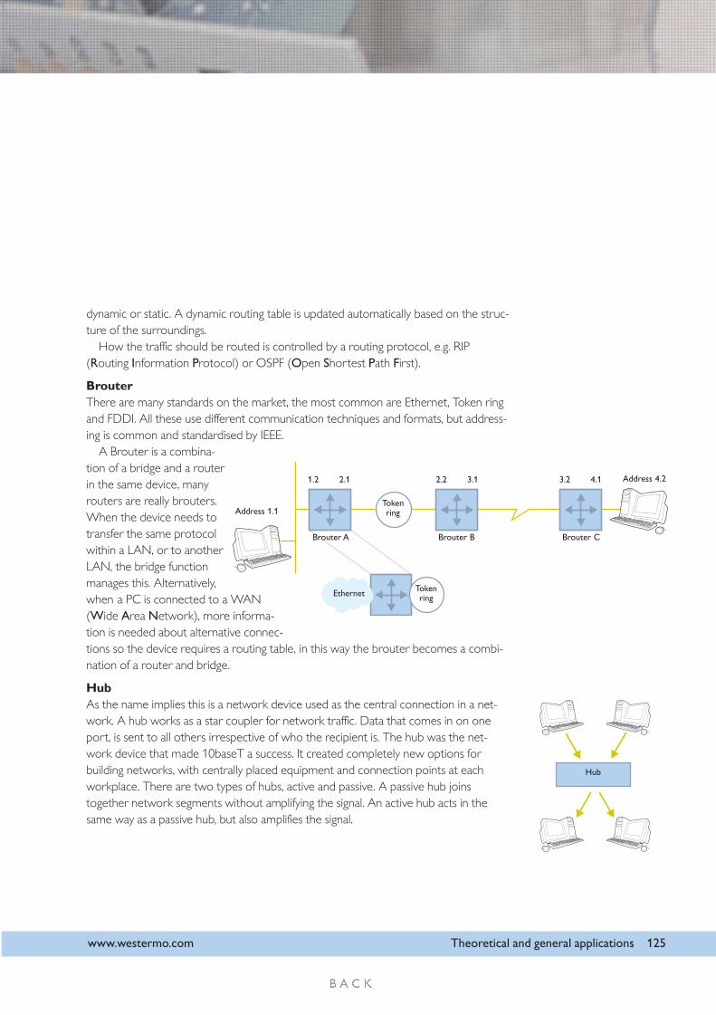
BrouterThere are many standards on the market, the most common are Ethernet, Token ringand FDDI. All these use different communication techniques and formats, but address-ing is common and standardised by IEEE.
A Brouter is a combina-tion of a bridge and a routerin the same device, manyrouters are really brouters.When the device needs totransfer the same protocolwithin a LAN, or to anotherLAN, the bridge functionmanages this. Alternatively,when a PC is connected to a WAN(Wide Area Network), more informa-tion is needed about alternative connec-tions so the device requires a routing table, in this way the brouter becomes a combi-nation of a router and bridge.
HubAs the name implies this is a network device used as the central connection in a net-work. A hub works as a star coupler for network traffic. Data that comes in on oneport, is sent to all others irrespective of who the recipient is. The hub was the net-work device that made 10baseT a success. It created completely new options forbuilding networks, with centrally placed equipment and connection points at eachworkplace. There are two types of hubs, active and passive. A passive hub joinstogether network segments without amplifying the signal. An active hub acts in thesame way as a passive hub, but also amplifies the signal.
Brouter A
Ethernet
Address 1.1
Address 4.21.2 2.1 2.2 3.1 3.2 4.1
Brouter B Brouter C
Tokenring
Tokenring
Hub

126 Theoretical and general applications www.westermo.com
SwitchA switch is similar to a hub in that it is the central connection point for the network.The difference is that the switch keeps track of which devices are connected to itsrespective ports. When data is sent to a device in the network, the recipient address ischecked by the switch and data is only sent to the port where the device is connected(switched network). In this way the network is not overloaded with unnecessary traf-fic. Another advantage is an increase in security, as it is more difficult to access informa-tion that is not intended for the computer in question.
A layer 2 switch is a type of bridge.A layer 3 switch is a type of router.
Consequently, in some contexts the terms switch, bridge and router are used synony-mously.
Managed and unmanaged switches are other terms that are used regularly. The dif-ference is that you can communicate with a managed ( monitorable) switch, whichnormally takes place through SNMP, also refer to pages 138 to 143.
GatewayA gateway connects together networks, but its main task is to convert data betweendifferent protocols, for example, between AppleTalk and TCP/IP. Apart from convert-ing protocols, a gateway also supports different formats, character codes, addresses,etc.
FirewallA firewall is special equipment or software that only forwards traffic when specificrequirements have been met, other traffic is refused. This means that users in a net-work can be protected from prohibited traffic. Usually there is a firewall between alocal network and the Internet. You can also have firewalls on internal networks ortogether with equipment that makes it possible to call into a network. Rules varying indegree of complexity are used to determine what the firewall allows to pass. When,where and how a firewall is used is controlled by the security requirements placed onthe network. There are a large number of products on the market to choosebetween, from a combination of hardware and software solutions to firewalls that canbe downloaded as “freeware” and used on your own computer.
Switch