industrial measuring technology from carl zeiss · the quality of the construction of zeiss form...
TRANSCRIPT

I n d u s t r i a l M e a s u r i n g T e c h n o l o g y f r o m C a r l Z e i s s
Form measuring systems
We make it visible.

Maximum quality – from produc-
tion to service
The f inishing of vital machine components is
performed by specialists. Quality control of our
products fol lows the most str ingent internal
testing procedures which are more exacting than
the specified standards.
Furthermore, Carl Zeiss also delivers first class
service whether it concerns a metrology question,
maintenance or repair. Thanks to our network of
regional offices, you receive the expert help you
need within a short time.
Overview
Machine concept
Measuring range
Inspection equipment from Carl Zeiss for the production floor.
2
The right system for every requirement
Rondcom 41: The compact form measuring station with manual and software alignment of the workpiece.
Rondcom 44/45: The highly accurate system with a broad range of applications. Easy upgrade to a full CNC form measuring station.
Rondcom 47/55: The highly accurate form measuring systems with manual or complete CNC-controlled rotary table for large workpieces.
Rondcom 60: The reference form measuring machine for maximum accuracy through design quality.
Rondcom 72/75: The highly accurate spindle form testers for oversizedworkpieces in the automotive industry.
The Rondcom form measuring line from Carl Zeiss allows you to properly meet the requirements of the various measuring areas. The Rondcom41, 44 and 54 table instruments for highly accurate workpieces are ideal up toa measuring height of 500 mm max. (optional).
The Rondcom 47, 55 and 60 systems can accommodate workpieces up to 800 mm (optional) and 60 kg (100 kg optional).
The Rondcom 72 and 75 spindle form testers from Carl Zeiss are designed foroversized workpieces in the automotive industry. Cylinder heads, crankshaftsand engine blocks are just a few of the typical applications.
Carl Zeiss offers a complete pro-
duct line for industrial metrology.
From the small “handy surf” for
surface measurements up to the
large systems used for measuring
large vehicles – whatever your
application, Carl Zeiss has the
right metrology equipment.
Our product line also offers highly
accurate measuring machines for
form, contour and surface measu-
rements.
Flexibility
Operation
Software
Precision
3
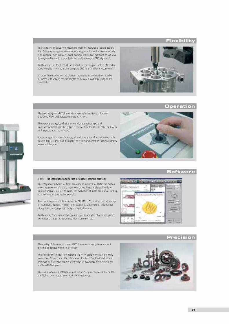
The entire line of ZEISS form measuring machines features a flexible design:Carl Zeiss measuring machines can be equipped either with a manual or fullyCNC capable rotary table. A special feature: the manual Rondcom 44 can alsobe upgraded onsite to a form tester with fully automatic CNC alignment.
Furthermore, the Rondcom 54, 55 and 60 can be equipped with a CNC detec-tor-and-stylus system to enable complete CNC runs for volume measurement.
In order to properly meet the different requirements, the machines can be delivered with varying column heights or increased load depending on theapplication.
The basic design of ZEISS form measuring machines consists of a base, Z column, R axis and detector-and-stylus system.
The systems are equipped with a controller and Windows-based computer workstations. The system is operated via the control panel or directlywith support from the software.
Customer-specific system furniture, also with an optional anti-vibration table,can be integrated with an instrument to create a workstation that incorporatesergonomic features.
The quality of the construction of ZEISS form measuring systems makes it possible to achieve maximum accuracy.
The key element in each form tester is the rotary table which is the primarycomponent for precision. The rotary tables for the ZEISS Rondcom line areequipped with air bearings and achieve radial accuracies of up to 0.02 µm on the reference point.
The combination of a rotary table and the precise guideway axes is ideal forthe highest demands on accuracy in form metrology.
TIMS – the intelligent and future-oriented software strategy
The integrated software for form, contour and surfaces facilitates the exchan-ge of measurement data, e.g. from form or roughness analyses directly to contour analysis, in order to permit the evaluation of micro-contours accordingto specific requirements, for example.
Polar and linear form tolerances as per DIN ISO 1101, such as the calculationof roundness, flatness, cylinder form, coaxiality, radial runout, axial runout,straightness, and perpendicularity, are typical features.
Furthermore, TIMS form analysis permits special analyses of gear and pistonevaluations, statistic calculations, Fourier analyses, etc.

TIMS – the intelligent and future-oriented software strategy.
Software overview
4
Measurement
The “measurement window” offers easy access to
all relevant functions, such as:
Control of all motorized axes
Computer-supported calibration
Enter workpiece data
Specification of measuring requirements
Measure polar and linear parameters
Set automatic functions
Automatic fast tilting, leveling
and centering
... in accordance with optimum customer criteria
such as:
Centering according to roundness
Tilting/centering according to roundness
Tilting according to straightness
Leveling according to flatness
Analysis
The profile is available in an analysis window with
a wide range of evaluations immediately after the
measurement.
Perfect profile processing and post-measure-
ment calculation with other filter settings,
analysis methods, etc.
Different display possibilities: 2D, 3D, linear,
material percent, amplitude density, Fourier
analysis
Clear display of selected windows
Up to 10 profiles can be edited simultaneously
Gear tooth tip analysis function
QS-STAT output

Data processingRoundness evaluation LSC Gaussian compensating circle (Least Square Circle Method)
MZC (Minimum Zone Circle Method)MIC (Maximum Inscribed Circle Method)MCC (Minimum Circumscribed Circle Method)NC (No Correction)
Tested features polar Roundness, flatness, concentricity, parallelism, coaxiality, cylindricity, squareness,total run, radial runout, axial runout, diameter and height deviation
linear Straightness, tapering (cylindricity), squareness, parallelismDisplay unit Color monitor Printer Color inkjet printer or laser printerDisplayable values Measuring conditions, measuring parameters, graphic display, Fourier analysis, Abbott curve, ADCMeasuring units mm, inch (selectable)Filter type Gaussian, 2 RC (Digital)Filter setting Low pass filter 15, 50, 150, 500 / revolution, or without limitationfor roundness and straightness High pass filter 15–150, 15–500 / revolution, 50–500 / revolution
Critical wavelength 0.25; 0.8; 2.5; 8 mmMagnfication 50, 100, 200, 500, 1,000, 2,000, 5,000, 10,000, 20,000, 50,000, 100,000x, AutoBroken surface angular range 0,1°–8° (in 1° increments)
Limit Each value in 0.1 mm icrementsData interface RS-232C
100,000x magnification and detail zoom
Data fadeout for the analysis of segments, broken
surfaces, gear wheels
Customer-specific displays
Change the scales, line colors and thickness, zoom
etc.
Extensive measurement logs can be printed in
color using the print layout and designed accor-
ding to your own needs.
All profiles and detail sections
Result lists, measurement conditions, com-
ments
Add your company's logo, workpiece drawings
and pictures
Export protocol elements for other software
applications
5

6
Manual form measuring machines
Designed for fast, easy and precise completion
of form measuring tasks
Measure polar and linear parameters, e.g.
cylinders, straightness and concentricity, etc.
High-quality axes with rotary table on air
bearings, optional 500 mm Z column
Variable measuring range and probing force
Easy to use
Semi-automatic processes
CNC analysis with printout
TIMS measuring software with assistant
function for centering and leveling
Workpieces up to 25 kg max.
Extensive accessories permit flexible use
Menu-guided, fast tilting and centering
For perfect cooperation with the user when
preparing the measurement.
Rondcom 41The compact form measuring station with manual,software-supported alignment of the workpiece.
Accuracy through mechanical
precision

7
Rondcom 44 /54The highly accurate system with a broad range of applications.Easy upgrade to a full CNC form measuring station.
Maximum accuracy and high flexibility through
newly developed detector-and-stylus system
New: easy on-site upgrade to full CNC capable
form measuring system
High productivity resulting from time savings
during set up: rough alignment – maximum
measuring accuracy
Compact table form measuring station
Highly accurate rotary table with air bearings
for wear-free radial runout
Additional linear scale in the R-axis in the
R44 and R54 standard systems
TIMS software with assistant function for
centering and leveling
Rondcom 44 with manual rotary table,
Rondcom 54 with fully automatic workpiece
alignment
Different variations with the manual or CNC
detector and stylus systems, Z = 300 mm or
500 mm
Manual/CNC form measuring machines
Rondcom 44 and Rondcom 54 are equipped with
a new type of correction software which permits
maximum measuring accuracies with a rough
alignment of the workpiece.
Rondcom 44
Rondcom 54 withintegrated furniture design

8
Manual/CNC form measuring machines
Rondcom 47/ 55The higly accurate form measuring systems with manualor complete CNC-controlled rotary table for large workpieces.
Fast, easy and precise completion of form
measuring tasks
Very high accuracies resulting from rotary table
on air bearings
TIMS measuring software with assistant
function for centering and leveling with
Rondcom 47
Automated fast tilting and centering of the
workpiece with Rondcom 55
CNC programming from measurement to
evaluation to printout, easy with teach-in
Optional manual or CNC-controlled detector-
and-stylus system
Optional with incremental glass scale also in
the R axis
Standard machine with Z = 350 mm and 60 kg
max. load
Variable measuring range and probing force
Numerous possible variations Rondcom 47 with manual rotary table
Rondcom 55 with fully-automatic rotary table

9
CNC form measuring machines
Rondcom 60The reference form measuring machine for maximum accuracythrough design quality.
Automated fast tilting and centering of the
workpiece with CNC measurements
Programming from measurement to evaluation
to printout, easy with teach-in
Optional manual or CNC-controlled detector-
and-stylus system
Incremental glass scale also in the R axis
Standard machine with Z = 500 mm and 60 kg
max. load
Variable measuring range and probing force
Numerous possible variations
High-end CNC form measuring machine for
highest precision completion of form measur-
ing tasks
Most accurate form measuring station in its
class
Design quality resulting from distortion-free
granite base and air bearings in all axes
Data transmission for contour
The profiles can be optionally transmitted to the
contour evaluation module for processing, e.g. for
analysis of angles and gaps.
...easy to use, both manual and automatic!
Different 3D profile displays with choice of viewing
angle via tilting and rotating.

Rondcom 72/75The highly accurate spindle form testers for oversized workpieces in the automotive industry.
Manual/CNC-controlledspindle form testers
10
Highest accuracy form measuring on over-sized
workpieces
Typical applications: cylinder heads, engine
blocks, crank shafts
Manual or CNC controlled Rondcom 72
Rondcom 75 with granite base and air
bearings, completely CNC controlled
Max. load up to 1000 kg with Rondcom 75
Extensive accessories permit versatile use
Windows-based TIMS software with teach-in
programming
� Rondcom 72

11
Examples of typical applications forRondcom 72/75:measurement of cylinder heads,engine blocks and crankshafts
Rondcom 75
12
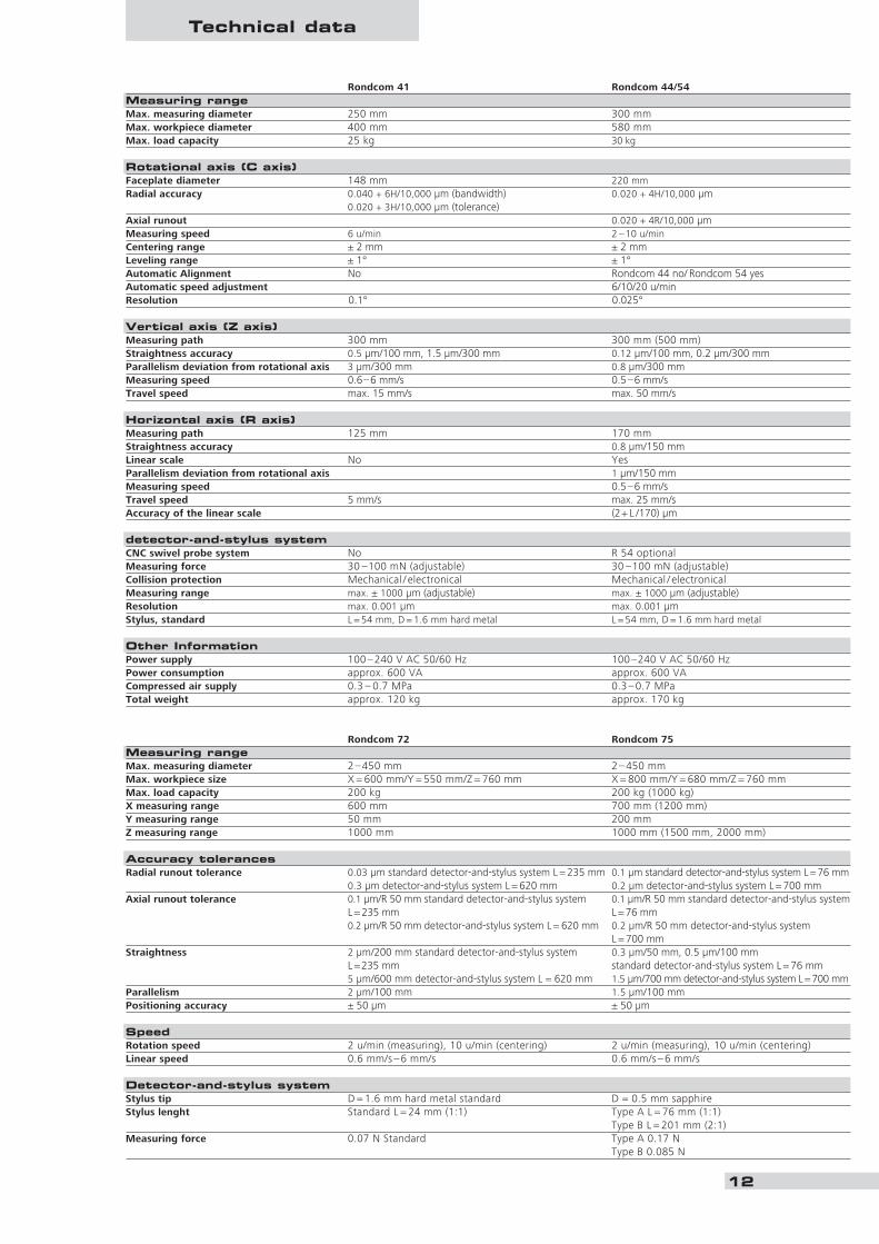
Rondcom 41 Rondcom 44/54Measuring rangeMax. measuring diameter 250 mm 300 mmMax. workpiece diameter 400 mm 580 mmMax. load capacity 25 kg 30 kg
Rotational axis (C axis)Faceplate diameter 148 mm 220 mmRadial accuracy 0.040 + 6H/10,000 µm (bandwidth) 0.020 + 4H/10,000 µm
0.020 + 3H/10,000 µm (tolerance)Axial runout 0.020 + 4R/10,000 µmMeasuring speed 6 u/min 2 –10 u/minCentering range ± 2 mm ± 2 mmLeveling range ± 1° ± 1°Automatic Alignment No Rondcom 44 no/ Rondcom 54 yesAutomatic speed adjustment 6/10/20 u/minResolution 0.1° 0.025°
Vertical axis (Z axis)Measuring path 300 mm 300 mm (500 mm)Straightness accuracy 0.5 µm/100 mm, 1.5 µm/300 mm 0.12 µm/100 mm, 0.2 µm/300 mmParallelism deviation from rotational axis 3 µm/300 mm 0.8 µm/300 mmMeasuring speed 0.6–6 mm/s 0.5–6 mm/sTravel speed max. 15 mm/s max. 50 mm/s
Horizontal axis (R axis)Measuring path 125 mm 170 mmStraightness accuracy 0.8 µm/150 mmLinear scale No YesParallelism deviation from rotational axis 1 µm/150 mmMeasuring speed 0.5–6 mm/sTravel speed 5 mm/s max. 25 mm/sAccuracy of the linear scale (2+ L /170) µm
detector-and-stylus systemCNC swivel probe system No R 54 optionalMeasuring force 30 –100 mN (adjustable) 30 –100 mN (adjustable)Collision protection Mechanical / electronical Mechanical / electronicalMeasuring range max. ± 1000 µm (adjustable) max. ± 1000 µm (adjustable)Resolution max. 0.001 µm max. 0.001 µmStylus, standard L = 54 mm, D = 1.6 mm hard metal L = 54 mm, D = 1.6 mm hard metal
Other InformationPower supply 100–240 V AC 50/60 Hz 100 –240 V AC 50/60 HzPower consumption approx. 600 VA approx. 600 VACompressed air supply 0.3 – 0.7 MPa 0.3– 0.7 MPaTotal weight approx. 120 kg approx. 170 kg
Rondcom 72 Rondcom 75Measuring rangeMax. measuring diameter 2–450 mm 2– 450 mmMax. workpiece size X = 600 mm/Y = 550 mm/Z = 760 mm X = 800 mm/Y = 680 mm/Z = 760 mmMax. load capacity 200 kg 200 kg (1000 kg)X measuring range 600 mm 700 mm (1200 mm)Y measuring range 50 mm 200 mmZ measuring range 1000 mm 1000 mm (1500 mm, 2000 mm)
Accuracy tolerancesRadial runout tolerance 0.03 µm standard detector-and-stylus system L = 235 mm 0.1 µm standard detector-and-stylus system L = 76 mm
0.3 µm detector-and-stylus system L = 620 mm 0.2 µm detector-and-stylus system L = 700 mmAxial runout tolerance 0.1 µm/R 50 mm standard detector-and-stylus system 0.1 µm/R 50 mm standard detector-and-stylus system
L = 235 mm L = 76 mm0.2 µm/R 50 mm detector-and-stylus system L = 620 mm 0.2 µm/R 50 mm detector-and-stylus system
L = 700 mmStraightness 2 µm/200 mm standard detector-and-stylus system 0.3 µm/50 mm, 0.5 µm/100 mm
L =235 mm standard detector-and-stylus system L = 76 mm5 µm/600 mm detector-and-stylus system L = 620 mm 1.5 µm/700 mm detector-and-stylus system L=700 mm
Parallelism 2 µm/100 mm 1.5 µm/100 mmPositioning accuracy ± 50 µm ± 50 µm
SpeedRotation speed 2 u/min (measuring), 10 u/min (centering) 2 u/min (measuring), 10 u/min (centering)Linear speed 0.6 mm/s – 6 mm/s 0.6 mm/s – 6 mm/s
Detector-and-stylus systemStylus tip D = 1.6 mm hard metal standard D = 0.5 mm sapphireStylus lenght Standard L = 24 mm (1:1) Type A L = 76 mm (1:1)
Type B L = 201 mm (2:1)Measuring force 0.07 N Standard Type A 0.17 N
Type B 0.085 N
Technical data

13
Technical data
Accuracy information based on environmental temperatureof 20 °C ± 2 °C.
Subject to change as a result of technical modificationsand required export licenses.
R = Radius in mmH = Measuring height in mm
Rondcom 47/55 Rondcom 60Measuring rangeMax. measuring diameter 350 mm 420 mmMax. workpiece diameter 600 mm 680 mmMax. load capacity 60 kg 60 kg
Rotational axis (C axis)Faceplate diameter 290 mm 290 mmRadial accuracy 0.020 + 6H/10,000 µm (bandwidth) 0.020 + 6H/10,000 µm (bandwidth)
0.010 + 3H/10,000 µm (tolerance) 0.010 + 3H/10,000 µm (tolerance)Measuring speed 2 –10 u/min 2 –10 u/minCentering range ± 5 mm ± 5 mmLeveling range ± 1° ± 1°Automatic Alignment Rondcom 47: no/Rondcom 55: yes YesAutomatic speed adjustment 6/10/20 u/min 6/10/20 u/minResolution 0.1° 0.1°
Vertical axis (Z axis)Measuring path 350 mm (500 mm) 500 mm (800 mm)Straightness accuracy 0.15 µm/100 mm, 0.3 µm/300 mm 0.10 µm/100 mm, 0.25 µm/500 mmParallelism deviation from rotational axis 1.5 µm/350 mm 1.5 µm/500 mmMeasuring speed 0.6–6 mm/s 0.6–6 mm/sTravel speed max. 30 mm/s max. 30 mm/s
Horizontal axis (R axis)Measuring path 187 mm 220 mm Straightness accuracy 1 µm/100 mm 0.5 µm/200 mmLinear scale R 55 optional YesParallelism deviation from rotational axis 2 µm/100 mm 0.5 µm/200 mmMeasuring speed 0.6–6 mm/s 0.6–6 mm/sTravel speed max. 16 mm/s max. 20 mm/sAccuracy of the linear scale (2+ L /220) µm (2+ L /220) µm
Detector and stylus systemCNC swivel probe system R 55 optional optionalMeasuring force 30 –100 mN (adjustable) 30 –100 mN (adjustable)Collision protection Mechanical / electronical Mechanical / electronicalMeasuring range Max. ± 1000 µm (adjustable) Max. ± 1000 µm (adjustable)Resolution Max. 0.001 µm Max. 0.001 µmStylus, standard L = 54 mm, D = 1.6 mm hard metal L = 54 mm, D = 1.6 mm hard metal
Other InformationPower Supply 100 – 240 V AC 50 / 60 Hz 100– 240 V AC 50 / 60 HzPower consumption appox. 800 VA appox. 800 VACompressed air supply Supply pressure 0.5– 0.7 MPa Supply pressure 0.5 – 0.7 MPaTotal weight appox. 480 kg appox. 600 kg

60-2
2-7
32-e
00Pr
inte
d in
Ger
man
y00D
BD-T
S-IV
I/200
5 Po
o00P
rinte
d on
env
ironm
enta
lly-f
riend
ly, c
hlor
ine-
free
ble
ache
d pa
per
Carl Zeiss
Industrial Metrology
73446 Oberkochen/Germany
Sales: +49 1803 336 336
Service: +49 1803 336 337
Fax: +49 7364 203 870
E-Mail: [email protected]
Internet: www.zeiss.de/imt