industrial process monitoring and controlling using internet protocol and wireless technology
DESCRIPTION
to monitor and control industrial process by using this project1.motor on off control2.water level control3.temperature control lallim parallel port software is used.TRANSCRIPT

Industrial Process Monitoring And Controlling Using Internet Protocol And Wireless Technique
Chapter 1
INTRODUCTION
1.1 Introduction:
Nowadays the Internet is playing a very important role in different domains. During
the previous years a lot of research has been done for trying to develop applications, which
make it possible to supervise and control industrial processes using the World Wide Web.
Although different experiments have proven that this technology has a great impact in the
future there are still some problems.
It is often desirable to monitor or control industrial equipment from a remote location.
Whether for the purpose of controlling a process, monitoring performance or performing
remote diagnostics, the cost and time saving of remote monitoring can often justify large
expenditures in infrastructure costs. Fortunately, with the advent of the Worldwide Web and
low-cost Web server hardware, remote monitoring and control can often be added for very
little additional cost to the manufacturer.
Remote monitoring and intelligent maintenance is one of the most important criteria
for maximizing production and process plant availability. Wireless media has been
undergoing a rapid innovation process in search for a reliable, simple and business-viable
technology for fast, easy and inexpensive diagnosis of faults in process plants. With the
complexity and interdisciplinary nature of emerging engineering designs and solutions, it is
vital that groups working in industry and academia share information at a rapid pace, with the
collective aim of increasing product quality and reducing development time and costs. The
rapid growth of global internet connectivity, coupled with improved security norms and
standards, gives us a powerful tool to achieve these goals.
The internet protocol has made it possible to send a lot of data from one side of the
world to the other side in almost no time. The use of the Internet for real-time interaction of
the remote controlling and monitoring of the plants would give us many advantages. This
technology cannot only be used in the industry, but also in the field of medicine, education,
etc. Although all this looks promisingly two main problems should be faced before the web
based control and monitoring can be implemented. The first one is the aspect of time delay,
which can lead to irregular data transmission and data loss. In the worst-case this can make
the whole system unstable. The other one is the problem of security. When malicious hackers
Dept. of E&E 1 S.T.J.I.T. RNR

Industrial Process Monitoring And Controlling Using Internet Protocol And Wireless Technique
can grant access to a system the consequences can be catastrophic. Other problems concern
the distance or logistics. If something goes wrong with the system, a lot of time and
preparation can be needed before somebody can intervene to requirement specifications and
system implementation.
This project presents a practical approach to monitor and control the process in
industries by computer using IP connection. Internet Protocol (IP) is the protocol for
communication on the Internet. IP is responsible for sending the packet to its destination
along a route.
The user can monitor and control the process by using computer. Programming
software also will be used to program this microcontroller. By using this IP on this project, a
lot of advantages we can get such as the user can be at any place to monitor and control the
system as long as they have computer along with the internet connection. It also can maintain
the productivity and prevent losses of the product in industries.
Wireless data transmission is ubiquitous. It has touched all aspects of life from cordless
phones, garage door openers, wireless LANs at home and business to high-speed Internet
access in rural areas. Consumers have quickly embraced wireless technologies in pursuit of
simplicity, productivity and mobility.
In industrial automation, users have realized the benefits of adopting wireless
technologies in eliminating the need for cables in hard to reach areas within the plant,
increasing data availability and quality and monitoring and controlling remote assets that
otherwise were inaccessible. Several radio frequency technologies, such as licensed Very
High Frequency (VHF) and Ultra High Frequency (UHF) radios have been used for decades.
Due to license restriction and the complexity of the deployment, UHF/VHF radios required
radio experts to setup and maintain the systems. The allocation of radio spectrum for
Industrial, Scientific and Medical (ISM) license-free band have propelled the use of wireless
in industrial applications. Vendors were able to create products that are easy to deploy,
configure and maintain.
1.2 Necessity of project:
Dept. of E&E 2 S.T.J.I.T. RNR

Industrial Process Monitoring And Controlling Using Internet Protocol And Wireless Technique
Internet protocol is the protocols for communication on the internet. Industrial process
monitoring and controlling using internet protocol can be described as the whole of operations
performed to control or monitor a system situated in a closed network.
Protocol has key role in today's communication world, without protocol it is not possible
for one computer to communicate with another computer.
Using the power of internet, remote monitoring and controlling takes a new meaning. Use of
internet protocol and wireless technology provides greater flexibility to our project.
It also provides long range of operation as we are controlling by two PC’s which are
synchronized through internet protocol address. Closed loop control provides automatic
operation and important consideration is, it reduces the human power and it can save cost
from taking many employees and save time because the system can be monitored and
controlled by less number of persons. Wireless technology makes system more flexible as
there is an absence of wires.
1.3 Objectives of project:
The main objective of this project is aimed at monitoring and controlling the
industrial process with the help of internet protocol and wireless technique and it is purposely
designed to easier the user to monitor and control the process in industries by computer using
IP connection.
Long range of operation is provided
Closed loop control is used.
By using temperature and liquid sensors we can control temperature and liquid
levels automatically.
Chapter 2
Dept. of E&E 3 S.T.J.I.T. RNR

Industrial Process Monitoring And Controlling Using Internet Protocol And Wireless Technique
LITERATURE SURVEY
Egwin Warnier, Leena Yliniemi and Pasi Joensuu. [1] Nowadays the Internet is playing a
very important role in different domains. During the previous years a lot of research has been
done for trying to develop applications, which make it possible to supervise and control
industrial processes using the World Wide Web. Although different experiments have proven
that this technology has a great impact in the future there are still some problems. These
problems concern architectures, requirement specifications, and security aspects. This report
will give a brief overview about the design methods and architectures developed so far for the
Internet-based process control systems and also about the problems concerning security
aspects.
Internet based process control has been examined. Internet-based control is only an
extra control level added into the existing process control hierarchy. When designing
architecture the requirement specifications, user interface, universally platform-independent
programming languages and security measures are important issues. Internet technologies can
provide web clients a platform, not only for remotely.
Monitoring the behavior of process plants, but also for remotely controlling the plants
as well. One of the key problems in the Internet based process control is the Internet time
delay. If the Internet is heavily loaded, the responses may be delayed and the operator
corrections may take too long time for correcting the system. More advanced technologies
should be implemented to properly deal with the Internet transmission delay.
K. K. Soundrapandian, Manoj Rao and Sameer Khandekar [2]The development of a
remote-access real-time laboratory (RART-Lab) is described, and a case study is presented of
its application to a real-time mechanical engineering experiment, namely a study of thermo-
hydrodynamics of flow through mini-channels. (The study of such flows is vital for many
applications, ranging from electronics thermal management to fuel cells.) The RART-Lab
concept encompasses data acquisition during the experiment, storage, post-processing and
online transmission of data to multiple users logged on to their respective web browsers.
Control of the experimental process parameters (e.g. liquid mass flow rate and heater power
level) from one (or more) remote stations over the web in real time is also incorporated.
Online video images of the experimental facility, visualization modules and color-indexed
temperature data can be transmitted by webcam. The system developed has a friendly
graphical user interface. It also allows transmission of process parameter alarm signals via an
e-mail client server or via an SMS text message to a mobile telephone. Simultaneously,
Dept. of E&E 4 S.T.J.I.T. RNR

Industrial Process Monitoring And Controlling Using Internet Protocol And Wireless Technique
conventional chatting has also been incorporated to add vibrancy to inter-user
communication. In addition, three-dimensional computational fluid dynamics simulations
have also been done simultaneously with the real-time laboratory to mimic the experiments.
Such an integrated development greatly widens the possibilities of collaborative research,
development, simulation and experimentation, to overcome the need for the physical
proximity of the experimental hardware and experimenters. Such generic tools not only make
academic interactions and real-time data sharing more fruitful but also greatly facilitate joint
research and development activities between academia and the industrial community.
Nurul Izyan Binti Ahmad Tarmizi [3]. Practical approach to monitor and control the
process in industries by computer using TCP/IP connection. Transmission Control Protocol
(TCP) and the Internet Protocol (IP) are the protocols for communication on the Internet
where a stream of data that is sent over the Internet is first broken down into packets by the
TCP and IP is responsible for sending the packet to its destination along a route. The system
contains two main parts that is a local digital controller and graphical user interface (GUI)
application. The local digital controller which controls the system is implemented on a
PIC18F4620 microcontroller. The graphical user interface (GUI) application by using visual
basic makes the users easier to monitor and control the system when uses TCP/IP protocol.
The user can monitor and control the process by using computer. Programming software also
will be used to program this microcontroller. By using this TCP/IP on this project, a lot of
advantages we can get such as the user can be at any place to monitor and control the system
as long as they have computer along with the internet connection. It also can maintain the
productivity and prevent losses of the product in industries.
Sanath Alahakoon, Lilantha Samaranayake, Thilakasiri Vijayananda, Mats Leksell [4]
Ethernet today is the most widely used information carrier and the service provider for many
important applications in our day-to-day life such as e-mail, voice-image data and web based
information. It is also emerging strongly in the area of industrial communication. This paper
presents research and development being carried out to enhance the possibilities of using
standard TCP/IP Ethernet for real-time condition monitoring and distributed real-time
control.
Chapter 3
SYSTEM DEVELOPMENT
Dept. of E&E 5 S.T.J.I.T. RNR

Industrial Process Monitoring And Controlling Using Internet Protocol And Wireless Technique
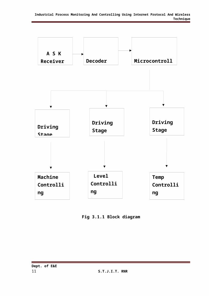
3.1 Model development:3.1.1 Block diagram:
Remote operation arrangement
PC arrangement inside Industry
Process Control arrangement inside the Industry
Dept. of E&E 6 S.T.J.I.T. RNR
Remote PC
Decoder A S K Receiver
Opto Couplers
Data Encoder
Communication Port
PC Inside Industry
Microcontroller
Internet Protocol
Internet
Protocol
User Inter Action Data
A S K Transmitter

Industrial Process Monitoring And Controlling Using Internet Protocol And Wireless Technique
Fig 3.1.1 Block diagram
3.1.2 Explanation:
1. User Interaction Data And Internet Protocol:
Dept. of E&E 7 S.T.J.I.T. RNR
Temp Controlling Process
Driving Stage Driving Stage Driving Stage
Level Controlling Process
Machine Controlling Process
Industrial Process Monitoring And Controlling Using Internet Protocol And Wireless Technique
It is nothing but the command which the key person of the industry enters into the
remote PC. Internet protocol is the method or protocol by which data is sent from one
computer to another on the internet. Each computer (known as a host) on the internet
has at least one IP address that uniquely identifies it from all other computer on the
internet.
2. Remote PC and PC Inside Industry:
It is the PC which is located in the remote area from which the commands are entered
and it is received by the PC which is inside the industry and the communication is
build up.
3. Communication Port:
Here we used Line Print Terminal (LPT) port as a communication port. This
communication port is found on the back of older PCs and is used for connecting
external devices. An LPT port has an 8-bit data bus and four pins for control output
(Strobe, Linefeed, Initialize, and Select In), and five more for control input (ACK,
Busy, Select, Error, and Paper Out). Its data transfer speed is at 12,000 k bit/s.
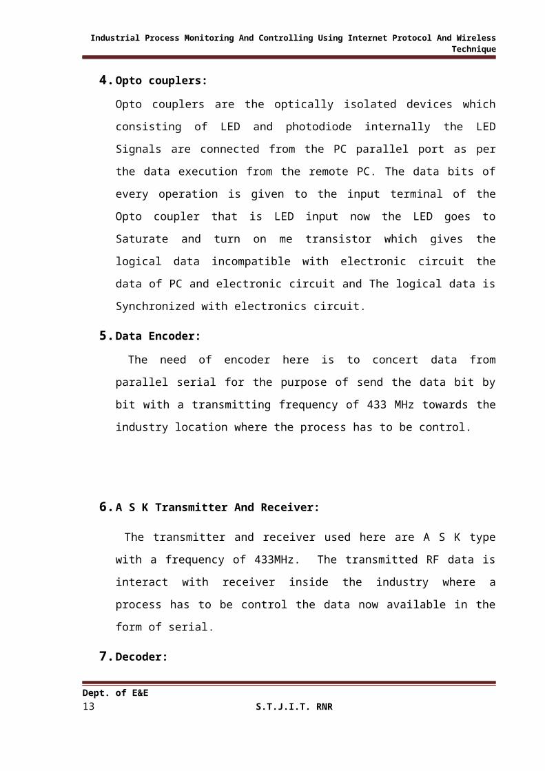
4. Opto couplers:
Opto couplers are the optically isolated devices which consisting of LED and
photodiode internally the LED Signals are connected from the PC parallel port as per
the data execution from the remote PC. The data bits of every operation is given to the
input terminal of the Opto coupler that is LED input now the LED goes to Saturate
and turn on me transistor which gives the logical data incompatible with electronic
circuit the data of PC and electronic circuit and The logical data is Synchronized with
electronics circuit.
5. Data Encoder:
The need of encoder here is to concert data from parallel serial for the purpose of
send the data bit by bit with a transmitting frequency of 433 MHz towards the
industry location where the process has to be control.
6. A S K Transmitter And Receiver:
Dept. of E&E 8 S.T.J.I.T. RNR

Industrial Process Monitoring And Controlling Using Internet Protocol And Wireless Technique
The transmitter and receiver used here are A S K type with a frequency of 433MHz.
The transmitted RF data is interact with receiver inside the industry where a process
has to be control the data now available in the form of serial.
7. Decoder:
The decoder has one input serial data terminal and four output data terminals each bit
which is available from the receiver Unit is convened into a parallel data with
synchronized frequency between encoder and decoder. The decoded data is connected
to microcontroller for further operation. .
8. Microcontroller:
The controller used here is 89 c51 which is haring inbuilt memory of 8k and it’s a
kind of flash memory So that modifications to the codes can be easily possible. The
data which is connected to the Controller is continuously monitoring and the
controller is so programmed that the particular process has to be controlled with
driving unit.
9. Driving Stage:
The driving unit is designed with relays and transistors from which the different
industrial processes can be possible to control. The need of relays here is to drive the
process control voltages with logical data from the Controller. Relays provide the
complete isolation between microcontroller and process system.
10. Temperature Controlling Process:
The temperature or oven Control is possible by just Connecting a thermister or a LM-
35 sensor the data can be Send to control the operation of over after reaching to a
particular temp.
11.Level Controlling Process:
The level Sensing process can be possible to Control after the float level Sensor
senses the level of the liquid using Control bit the particular level can be stopped
using the control bit.
12.Machine Controlling Process:
The machine operation can be controlled by a switching action from the controlling unit.
3.2 Hardware Design:
Dept. of E&E 9 S.T.J.I.T. RNR

Industrial Process Monitoring And Controlling Using Internet Protocol And Wireless Technique
3.2.1 Wiring diagram:
Fig 3.2.1 Wiring diagram
3.2.2 Working principle:
The system uses two PC one is remote PC from which the key person of the industry
send the required control signal and the PC which is in Industry communicate with Internet
protocol and intercommunication we can build and the process in the Industry gets controlled.
The data received from user interaction unit is in the form of logical data which has to
be entered into pc Internet protocol window the accessing of data from a protocol window is
in the form of binary bit the required bit can be set reset using bit set or reset icon. The
Internet protocol address is separate and unique for every PC. Each and every PC under
internet Connection can be identified with this unique code. Now from the remote PC the
required IP address has to be entered after this the communication is build up.
Now the data passes from internet Connectivity and reach the destination end which is
a PC inside the industry because of synchronization and IP address the data available from its
port. The L P T port we taken as a Communication port for interfacing with next Stage. The
data available from the port is as per the logical level of the PC which has to be modified and
Synchronization with electronic circuit for this purpose we are using Opto coupler unit here
for the purpose of Synchronization and Converting to a logical level of the next Circuit.
Dept. of E&E 10S.T.J.I.T. RNR
Industrial Process Monitoring And Controlling Using Internet Protocol And Wireless Technique
Opto couplers are the optically isolated devices which consisting of LED and
photodiode internally the LED Signals are connected from the PC parallel port as per the data
execution from the remote PC. The data bits of every operation is given to the input terminal
of the Opto coupler that is LED input now the LED goes to Saturate and turn on me transistor
which gives the logical data incompatible with electronic circuit the data of PC and electronic
circuit and The logical data is Synchronized with electronics circuit.
The available data from opted couplers now has to be sending for further control using
encoder. The data encoder used here is priority encoder which encodes the data to words me
transmitting unit.
The encoder uses 4 bit data input line and these data input, are connected to the
respective Opto coupler output as in data available from Opto coupler goes high the encoder
sends the data Serially to transmitter. The need of encoder here is to concert data from
parallel serial for the purpose of send the data bit by bit with a transmitting frequency of 433
MHz to words me industry location where the process has to be control. The transmitter and
receiver used here are A S K type with a frequency of 433MHz.
When the transmitted RF data is interact with receiver inside the industry where a
process has to be control the data now available in the form of serial. But for further process
the data has to be Convert in terms of parallel here we are using decoder which is a
Compatible operation with encoder. The decoder has one input serial data terminal and four
output data terminals each bit which is available from the receiver Unit is convened into a
parallel data with synchronized frequency between encoder and decoder. The decoded data is
connected to microcontroller for further operation.
The controller used here is 89 c51 which is haring inbuilt memory of 8k and it’s a kind
of flash memory So that modifications to the codes can be easily possible. The data which is
connected to the Controller is continuously monitoring and the controller is so programmed
that the particular process has to be controlled with driving unit.
The driving unit is designed with relays and transistors from which the different
industrial processes can be possible to control. The need of relays here is to drive the process
control voltages with logical data from the Controller. Relays provide the complete isolation
between microcontroller and process system. Different processes can be possible to Control
here we are using temperature Control level control and some machine operation Control. The
temperature or oven Control is possible by just Connecting a thermister or a LM 35 sensor the
Dept. of E&E 11S.T.J.I.T. RNR

Industrial Process Monitoring And Controlling Using Internet Protocol And Wireless Technique
data can be Send to control the operation of over after reaching to a particular temp. The level
Sensing process can be possible to Control after the float level Sensor senses the level of the
liquid using Control bit the particular level can be stopped using the control bit. The machine
operation can be controlled by a switching action from the controlling unit. This system
provides complete control over all the operation and process control in the industry with
unlimited range of operation.
3.2.3 MICROCONTROLLER
3.2.3 A) Introduction to Microcontroller:
Nowadays the introduction of a technology that has radically changed the way in
which we analyze and control the world around us, Born of parallel development in computer
Architecture and Integrated circuit fabrication, have seen the growth of the number of
personal computer users. From a handful of hobbyist and “hackers” to millions of Business,
industrial, government, defenses, Educational and Private users now enjoying the advantage
of inexpensive computing. A product of Microprocessor developed was Microcontroller.
The microcontroller which is a “True Computer on Chip”. The design of
Microcontroller incorporates all the futures in a Microprocessor: CPU, ALU, PC, SP and
Registers. It has also added the other futures needed to make a complete computer: ROM,
RAM, Parallel I/O, Serial I/O, counters and a clock circuit.
Like the Microprocessor and Microcontroller is a general purpose device but which is
meant to read data, perform limited calculation and control its Environment, based on those
calculations. The prime use of Microcontroller is to control the operation of a machine using
a fixed program that is stored in ROM and does not change over the life time of the system.
The 89C51 is a low power, high performance CMOS 8-bit Microcomputer with 8K
byte of flash programmable and Erasable ROM. The device is manufactured using ATMEL’s
high density, non-volatile memory technology and is compatible with the industry standard
80C51 and 80C52 instruction set and pin out. The On-chip Flash allows program to be re-
programmed in system or by a conventional non-volatile memory programmer by combining
a versatile 8-bit CPU with flash memory on a monolithic chip. The ATMEL 89C51 is a
powerful microcontroller which provides a highly flexible and cost effective solution to many
Embedded control applications.
3.2.3 B) PIN Configuration of 89C51:
Dept. of E&E 12S.T.J.I.T. RNR
Industrial Process Monitoring And Controlling Using Internet Protocol And Wireless Technique
Microcontroller is a true computer on chip the design incorporates all the features found in a
microprocessor. It is a 40 pin chip consisting of 4 ports which can be used either input ports
or output ports. A pin out of the 89C51 packaged in a 40 pin dual input package is as shown
in figure.
PORT O
Port O is an 8 bit open drain bi-directional I/O port. Each pin can sink 8 TTL I/P’s. It can
be configured to be multiplexed low order Address / Data bus during access to external
program and data memory. When a pin is to be used as an I/P, a 1 must be written to a
corresponding port O latch by the program, thus turning both of the transistor OFF, which
in turn causes the pin to float in high impedance state, and the pin is connected to I/P
buffer. When used as an O/P the pin latches that are programmed to a 0 will turn ON the
lower FET grounding the pin. All latches that are programmed to a 1 still float; thus,
external pull-up resistors will be needed to supply logic high when using port O as an O/p.
Post 0 also receives the code bytes during flash programming and outputs the code bytes
during program verification
PORT 1
Port 1 is an 8-bit bi-directional I/O port with internal pull-ups. The port 1 O/P buffers can
sink/source four TTL I/P’s. When 1’s are written to port 1 pin, they are pulled high by
internal pull-ups and can be used as I/P’s. Port 1 pins that are externally being pulled low
will source current in because of the internal pull-ups. In addition port 1.0 and port 1.1 can
be configured to be the timer/counter 2 external count I/P’s (P1.0/t2) and the timer counter
2 trigger I/P (P1.1/T2(Ex)) respectively.
Dept. of E&E 13S.T.J.I.T. RNR

Industrial Process Monitoring And Controlling Using Internet Protocol And Wireless Technique
(T ) P1.0.2 1
T (Ex) P1.12
P1.2
P1.3
P1.4
P1.5
P1.6
P1.7
RST
(R ) P3.0XD
(T ) P3.1XD
(INTO) P3.2
(INT1) P3.3.
(T ) P3.40
(T ) P3.51
(WR) P3.6
(RD) P3.7
XTAL2
XTAL1
GND
2
3
4
5
6
7
8
9
11
12
13
14
15
16
17
18
19
20
40
39
38
37
36
35
34
33
32
31
29
28
27
26
25
24
23
22
21
VCC
P0.0 (AD )0
P0.1 (AD )1
P0.2 (AD )2
P0.3 (AD )3
P0.4 (AD )4
P0.5 (AD )5
P0.6 (AD )6
P0.7 (AD )7
EA / VPP
ALE / PROG
PSEN
P2.1 (A )15
P2.6 (A )14
P2.5 (A )13
P2.4 (A )12
P2.3 (A )11
P2.2 (A )10
P2.1 (A )9
P2.0 (A )8
ATMEL89C52
Fig 3.2.3 b) Pin configuration of 89C51
PORT 2
Port 2 may be used as an input/output similar in operation to port 1. Port 2 emits the high
order address byte during fetches from external program memory and during accesses to
external data memory that use 16 bit addresses. In this application, Port 2 uses strong
internal pull-ups. When emitting 1’s. During excesses to external data memory that 8 bit
address, Port 2 emits the contents of the P2 Special function Register. Port 2 also receives
Dept. of E&E 14S.T.J.I.T. RNR

Industrial Process Monitoring And Controlling Using Internet Protocol And Wireless Technique
the high order address bits and some control signals during flash programming and
verification.
PORT 3
Port 3 is an input/output port similar to port 1. The input and output functions can be
programmed under the control of the P3 latches or under the control of various other
special function registers. The port 3 alternate uses are shown in the following table.
3.2.3 C) Features of 89C51:
1. Compatible with MCS-51TM Products.
2. 8K byte of in system re-programmable flash memory.
3. Endurance: 1000 write / Erase cycle.
4. Fully static operation.
5. 3 Level program memorial clocks.
6. 256 X 8 bit internal RAM.
7. 32 programmable I/O Line.
8. 3-16 bit timer/Counter.
9. 8-Interupt Source.
10. Programmable serial channel.
11. Low power, Ideal and Power down modes.
12. Four register Banks each containing 8 registers
Dept. of E&E 15S.T.J.I.T. RNR

Industrial Process Monitoring And Controlling Using Internet Protocol And Wireless Technique
3.2.4 Power Supply Unit:
Fig 3.2.4 Power supply unit
A DC power supply system, which maintains constant voltage irrespective of
fluctuations in the main supply or variation in the load, is known as Regulated Power supply.
The 7805 IC referred to fixed positive voltage regulator, which provides fixed voltage 5 volts.
The 7805 regulator is known as fixed voltage regulator.
Fixed –Voltage regulator design has been greatly simplified by the introduction of 3-
terminal regulator ICs such as the 78xx series of positive regulators and the 79xxx series of
negative regulators, which incorporate features such as built-in fold back current limiting and
thermal protection, etc. These ICs are available with a variety of current and output voltages
ratings, as indicated by the ‘xxx’ suffix; current ratings are indicated by the first part of the
suffix and the voltage ratings by the last two parts of the suffix. Thus, a 7805 device gives a
5V positive output at a 1a rating, and a 79L15 device gives a 15V negative output at a
100mA rating. 3-terminal regulators are very easy to use.
The regulators ICs typically give about 60dB of ripple rejection, so 1V of input ripple
appears as a mere 1mV of ripple on the regulated output. A rectified filter and unregulated
DC voltage is given to pin of IC regulator. A bypass capacitor is connected between input
and ground to bypass the ripples and oscillations. The output capacitor is connected between
output and ground to improve transient response. The unregulated input is applied to the IC
must be always more than the regulated output.
Dept. of E&E 16S.T.J.I.T. RNR

Industrial Process Monitoring And Controlling Using Internet Protocol And Wireless Technique
3.2.5 Opto coupler With Transistor Interface:
Fig 3.2.5 Opto coupler with Transistor Interface
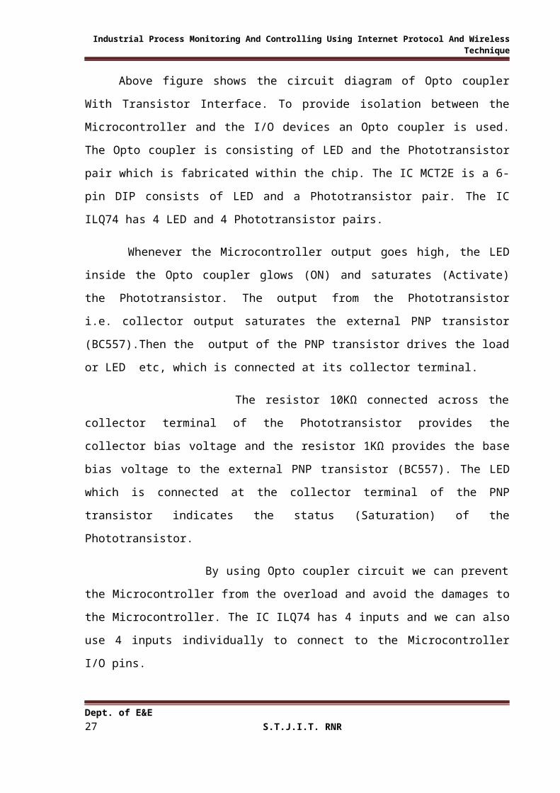
Above figure shows the circuit diagram of Opto coupler With Transistor Interface. To
provide isolation between the Microcontroller and the I/O devices an Opto coupler is used.
The Opto coupler is consisting of LED and the Phototransistor pair which is fabricated within
the chip. The IC MCT2E is a 6-pin DIP consists of LED and a Phototransistor pair. The IC
ILQ74 has 4 LED and 4 Phototransistor pairs.
Whenever the Microcontroller output goes high, the LED inside the Opto coupler
glows (ON) and saturates (Activate) the Phototransistor. The output from the Phototransistor
Dept. of E&E 17S.T.J.I.T. RNR

Industrial Process Monitoring And Controlling Using Internet Protocol And Wireless Technique
i.e. collector output saturates the external PNP transistor (BC557).Then the output of the
PNP transistor drives the load or LED etc, which is connected at its collector terminal.
The resistor 10KΩ connected across the collector terminal of the Phototransistor
provides the collector bias voltage and the resistor 1KΩ provides the base bias voltage to the
external PNP transistor (BC557). The LED which is connected at the collector terminal of the
PNP transistor indicates the status (Saturation) of the Phototransistor.
By using Opto coupler circuit we can prevent the Microcontroller from the
overload and avoid the damages to the Microcontroller. The IC ILQ74 has 4 inputs and we
can also use 4 inputs individually to connect to the Microcontroller I/O pins.
Dept. of E&E 18S.T.J.I.T. RNR

Industrial Process Monitoring And Controlling Using Internet Protocol And Wireless Technique
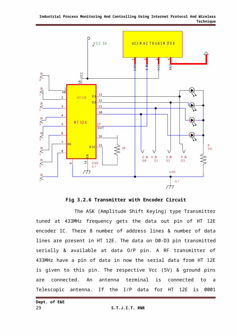
3.2.6 Transmitter with Encoder Circuit:
D I
N2
VC
C2
GN
D1
AN
T4
43 3 M HZ T R A NS M ITE R
D010
A12
A78
A34
A45
GN
D9
OSC16A5
6
D111
A01
A23
D OUT17
D313
A67
OSC15
EN
14
D212
VC
C1
8
HT 12 E
HT12E
330ER
G?
GND
G?GND
V CC 5V
A0
IN
A1
IN
A3
IN
A4
IN
A5
IN
A2
IN
A6
IN
A7
IN
D0D IN
D1D IN
D2D IN
D3D IN
1M
Fig 3.2.6 Transmitter with Encoder Circuit
The ASK (Amplitude Shift Keying) type Transmitter tuned at 433MHz frequency
gets the data out pin of HT 12E encoder IC. There 8 number of address lines & number of
data lines are present in HT 12E. The data on D0-D3 pin transmitted serially & available at
data O/P pin. A RF transmitter of 433MHz have a pin of data in now the serial data from HT
12E is given to this pin. The respective Vcc (5V) & ground pins are connected. An antenna
terminal is connected to a Telescopic antenna. If the I/P data for HT 12E is 0001 (Binary) the
D0-D3 bits transmitted serially & 433MHz transmitter transmit these bits in the form of RF
waves through an transmitting antenna.
The encoder inputs connected in different application like sensors, keyboard to enter
the sensor data. HT12E is a series of CMOS LSIs for remote control. The encoders of this
type are capable of encoding 12bits; consisting of N address bits and 12-N data bits. The
Dept. of E&E 19S.T.J.I.T. RNR

Industrial Process Monitoring And Controlling Using Internet Protocol And Wireless Technique
HT12E has 8 address bits and 4 data bits. The data that is set on these data lines is sent
serially along with the bits set on the address lines. The address bits are sent in prior to the
data bits. The data as well as the address is transmitted in four successions. The data consists
of differing lengths of positive going pulses for ‘1’ and ‘0’.The pulse width for ‘0’ is twice
the pulse width of ‘0’.The frequency of these pulses may lie in between 1.5KHz to 7KHz,
depending on the oscillator frequency.
Dept. of E&E 20S.T.J.I.T. RNR

Industrial Process Monitoring And Controlling Using Internet Protocol And Wireless Technique
3.2.7 Receiver with Decoder Circuit:
D O
UT
2
AN
T4
VC
C2
GN
D1
43 3 M HZ R E C E IV E R
330ER
G?
GND
V CC 5V
A0
IN
A1
IN
A3
IN
A4
IN
A5
IN
A2
IN
A6
IN
A7
IN
D0D OUT
D1D OUT
D2D OUT
D3D OUT
A67
A56
A45
A34
A23
A12
A01
D IN14
OSC16
OSC15
D313
D212
D111
D010
VC
C1
8G
ND
9
A78
HT
12D
VT17HT12D
..
BC 548
T
1KR
56K
R
Fig 3.2.7 Receiver with Decoder Circuit
The Receiver CKT is arranged as shown above. The 433MHz RF receiver (ASK type)
gets the data from antenna & the serial data is available at its data O/P pin. The corresponding
+Vcc & GND pins are connected to +5V source.
HT 12D Decoder decodes the serial data to parallel & it is available at D1- D4 data
bits the oscillating resistor of 51K is connected to its oscillating pins (pin 15 pin16) Pin 17 is
considered as going high when Transmitter starts generating & sending RF wave the pin 17 is
connected to a transistor & an LED which glows & indicates the link between Transmitter &
Receiver. If a data bit of 1010 is applied to the D0-D3 of HT 12E is Transmit serially.
Transmit 433MHz & now through Transmitter& Receiver receives the data bits & HT 12D
decodes the serial data bits to parallel & the same data i.e. 1010 is available at D1-D4 pins of
HT 12D.
Dept. of E&E 21S.T.J.I.T. RNR

Industrial Process Monitoring And Controlling Using Internet Protocol And Wireless Technique
The decoder outputs are connected to microcontroller, LCD, relays or motor driver
circuit. HT-12D decoder is also a series CMOS LSIs for the remote control applications. The
decoder is analogous to the encoder that is specified earlier. It is also capable of decoding 12
bits of information that consists of N address bits and 12-N data bits. It has 8 address and four
data lies.
For the proper operation of the encoder/decoder pair, the address on the address lines on
both the ICs must be the same. The decoder receives serial address and data from its
corresponding series of encoders that are transmitted by the RF transmitter. Then it compares
the serial data obtained twice continuously with its location address. If both of them are
matched, the input data codes are decoded and transferred to the output pin. The VT pin also
goes high to indicate the valid transmission. The internal operating frequency is 50 times
greater than the oscillating frequency of HT12E depends on the values of timing register on
the pin OSC1 and OSC2.
Dept. of E&E 22S.T.J.I.T. RNR
Industrial Process Monitoring And Controlling Using Internet Protocol And Wireless Technique
3.2.8 Relay Interface:
Fig 3.2.8 Relay Interface
The circuit diagram shows the connection of Relay Driver Circuit. When the logic signal
from the Buffer O/P is applied to base of the transistor through resistor 1KOhm the starts
conducting, it energizes the relay. The transistor act as a small signal amplifier resistor of
1KOhm is used to provide proper emitter base voltage to turn the transistor to ON state from
OFF state.
Relay is an electromechanical switch & it works on the principled energizing an
electromagnet. It consists of primary coil, 2 contacts one is normally open contact “NO” &
the other is normally closed contact “NC”& pole normally identified a common. When relay
is in off state the pole is connected to normally closed (NC contact).The load is connected to
the relay as shown in above circuit diagram. The load may be a fan or dc motor or heater coil,
when transistor starts conducting current starts flowing through the coil. Which develops its
Dept. of E&E 23S.T.J.I.T. RNR

Industrial Process Monitoring And Controlling Using Internet Protocol And Wireless Technique
own magnetic flux when the strength of current is suitable; a sufficient flux when produced
attracts the pole to make contact with normally open position ‘NO’. Hence the load
connected to it performs its operation until the contact is broken. A diode connected in
parallel across the primary coil is to eliminate the effect of back EMF on the transistor.
Relays have great application in industry. Using the principle of energizing an Electromagnet
we can handle large voltages & current application without the risk of shocks.
Dept. of E&E 24S.T.J.I.T. RNR
Industrial Process Monitoring And Controlling Using Internet Protocol And Wireless Technique
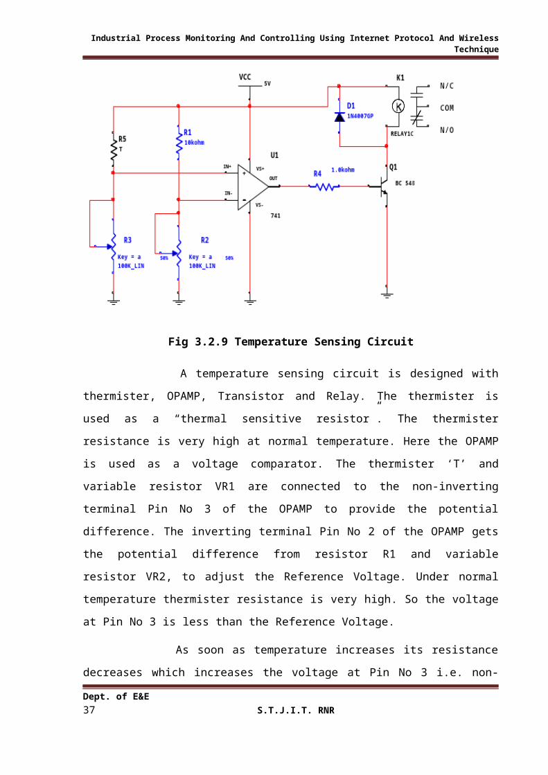
3.2.9 Temperature Sensing Circuit:
Fig 3.2.9 Temperature Sensing Circuit
A temperature sensing circuit is designed with thermister, OPAMP, Transistor and
Relay. The thermister is used as a “thermal sensitive resistor”. The thermister resistance is
very high at normal temperature. Here the OPAMP is used as a voltage comparator. The
thermister ‘T’ and variable resistor VR1 are connected to the non-inverting terminal Pin No 3
of the OPAMP to provide the potential difference. The inverting terminal Pin No 2 of the
OPAMP gets the potential difference from resistor R1 and variable resistor VR2, to adjust the
Reference Voltage. Under normal temperature thermister resistance is very high. So the
voltage at Pin No 3 is less than the Reference Voltage.
As soon as temperature increases its resistance decreases which increases the voltage
at Pin No 3 i.e. non-inverting terminal of the OPAMP. Now because of this condition the
potential difference between two inputs at comparator also changes and the output of the
comparator goes from its low to high state to activate (Saturate) the transistor. The collector
of the transistor further drives relay.
As long as the temperature is maintained high the OPAMP output remains in the same
state. When the temperature falls down on thermister, its resistance goes to increase. This
Dept. of E&E 25S.T.J.I.T. RNR

Industrial Process Monitoring And Controlling Using Internet Protocol And Wireless Technique
decrease the voltage at Pin No 3. Because of this condition the OPAMP i.e. comparator
output changes from its high to low state. At this instant the transistors goes to cutoff and
deactivate the relay.
Dept. of E&E 26S.T.J.I.T. RNR
Industrial Process Monitoring And Controlling Using Internet Protocol And Wireless Technique
3.2.10 Water Sensing Circuit:
Fig 3.2.10 Water Sensing Circuit
Above figure shows the circuit diagram of Water Sensing. It consists of Water Sensor
(Copper Conducting Plates or Probes), OPAMP, Transistor and Relay. The Water Sensor is
used for sensing the water level. The input probes are inserted in the well, storage tank or
submersible system. Here the OPAMP is used as a voltage comparator. The Sensor and
variable resistor VR1 are connected to the non-inverting terminal Pin No 3 of the OPAMP to
provide the potential difference. The inverting terminal Pin No 2 of the OPAMP gets the
potential difference from resistor R1 and variable resistor VR2, to adjust the Reference
Voltage.
When there is no water in the storage tank, well etc then the water resistance between
the input probes is more. At this condition the voltage at Pin No 3 is less than the reference
voltage and the output of the comparator is at low state which cutoff the transistor.
If the input probes get the sufficient water the resistance between the probes decreases
and the voltage at Pin No 3 increases which is more than the reference voltage. Now because
of this condition the potential difference between two inputs(Pin No 3 & Pin No 2 ) at
comparator also changes and the output of the comparator goes from its low to high state
Dept. of E&E 27S.T.J.I.T. RNR

Industrial Process Monitoring And Controlling Using Internet Protocol And Wireless Technique
which activate (Saturate) the transistor. Then the output of the transistor is given to the
microcontroller for further manipulation.
3.2.9 Hardware model circuit
Dept. of E&E 28S.T.J.I.T. RNR
Industrial Process Monitoring And Controlling Using Internet Protocol And Wireless Technique
3.3 Software Design:
3.3.1Software used:
LALIM PARALLEL PORT CONTROL BASIC
3.3.2 Explanation of software:
Lalim parallel port control can control hardware through the parallel port (printer
port) and can also control a remote PC parallel port through a network. Most of engineering
industry using PC to control hardware with using additional I/O card but with lalim parallel
port control, you can use your default printer port controlling external device such as
switching on/off light or control electronic devices. What does this program trigger the
parallel port (printer port)’s data pin by your command. For example when you trigger pin 2,
your printer port’s pin 2 becomes +5 volt. With this +5 volt, you can build your own
electronic circuit to drive other external device. You can also build a simple circuit to test it
by connecting a LED with 1 K ohm resister direct to it.
3.3.3 Working of software:
The system divided in to two parts, the client side (remote PC) & server side (PC
inside the industry). In both side PC’s software called Lalim Parallel Port Controllable Basic
is installed. in client side PC double click on icon “Lalim parallel port control” a dialogue
box will appear like this in server PC also double click on same icon &same dialogue box
will appear. In server PC click on option “Connect as Server”, another “Server “ dialogue box
will appear, in that IP address will be there and that same IP address should be entered into
the client pc after entering IP address click the option “Connect” now both the pc are
synchronized. From client PC we can give the commands .Because of synchronization of
both PC that commands transferred to the server and those signals are used for further
process.
Dept. of E&E 29S.T.J.I.T. RNR

Industrial Process Monitoring And Controlling Using Internet Protocol And Wireless Technique
3.4 PCB Design:
3.4.1 PCB Layout:
Fig 3.4.1 PCB layout
3.4.2 PCB Preparation
Dept. of E&E 30S.T.J.I.T. RNR

Industrial Process Monitoring And Controlling Using Internet Protocol And Wireless Technique
Printed Circuit Board, popularly known as PCB, PCB is a piece of plastic insulating
board, on one side of which a complete layout diagram of an electronic circuit consisting of
copper silver conducting paths is printed by a special photo etching process.
Construction:
The steps involved in the manufacturing of PCB are as follows:
Design and preparation
Pattern Design
Resist Application
Etching
Clearing and resist remover
Finishing
1) Design and preparation:
Artwork should be prepared on transparent polystyrene film using block ink or
adhesive tapes and pads. In modern technique screen printing method is used for art working
of PCB. This is the primary step in fabricating the PCB.
2) Pattern Design:
In industrial work, pattern is usually transformed to the surface of the laminate by
means of screen printing or by photographic method.
3) Resist application:
Adhesive tapes and pads which have high chemical resistance and excellent adhesion
can be attached to copper clad laminate.
4) Etching:
Etching sol can be prepared using available etchers like ferric Chloride, cupric
chloride etc. Ferric chloride is popularly used. Etching can be carried out in a spray etching
chambers. Few drops of HCL can be added to FECL3 to spread an etching action. The
Etching process may take 30-40 min depending upon the PCB.
5) Clearing and Resist Removal:
Dept. of E&E 31S.T.J.I.T. RNR

Industrial Process Monitoring And Controlling Using Internet Protocol And Wireless Technique
After etching, board should be washed under running water and then dried by
applying turpentine pads or spirit, the tapes can be cleaned off from PCB, Now printed
pattern will be clearly visible.
6) Finishing:
After PCB is cleaned, center of terminals can be center punched and holes can drill
over board. The drilling machine can be used to drill the holes. Then terminal points can be
lightly tinned. After wards suitable component can be mounted on PCB.
3.4.3 Soldering:
1. The two surfaces to be soldered should be thoroughly cleaned and made free from any
dust, grease or oil. Infect, through clearing of the PCB before beginning of the soldering
operation and proper tinning of the component leads at the time of soldering that
component achieves good result.
2. A small quantity of flux may be applied on the surfaces to be soldered. It is the function
of the soldering flux to keep away any oxide film. During soldering operation allow the
two surfaces to make a metallic contact and alloy with each other. The flux residue
should be removed after the soldering is done.
3. One of the most common problems in soldering is the application of insufficient heat.
The alloying action in soldering cannot be achieved without a uniform distribution of
heat b/n the solder and the metal being soldered. If hot solder is applied to a cold metal
or a cold solder is applied to a hot metal, there can never be a proper soldering action.
Soldering will be proper when the solder alloy is hot enough to remain in a liquid state,
as soldering is being done. To achieve a proper wetted soldering joint, heat up the
component terminal and slightly and apply solder by alloy right on the component lead
and instead of applying it on the soldering iron tip, melt the solder so that it flows over
the joint, Avoid putting solder metal and ensure that it is in the liquid state till it has
completely flowed over the joint. A perfect soldered joint would give a shiny bead like
appearance. Different electronic components used have different soldering temperatures.
Chapter 4
Dept. of E&E 32S.T.J.I.T. RNR

Industrial Process Monitoring And Controlling Using Internet Protocol And Wireless Technique
RESULT AND DISCUSSION
This system provides complete control over all the operation and process control in the
industry with unlimited range of operation. The machine operation can be controlled by a
switching action from the controlling unit.
In this dissertation we are controlling temperature by connecting LM 35 sensor and
fluid levels of some machines by float level sensors.
OUTPUT:
INPUT BIT STATUS RESULT OPERATION
D0 SET First device ON It may be either machine or lights operation
and we also provided level control
automatically.
D3 SET First device OFF DO
D2 SET Second device ON It may be either machine or lights operation
and we also provided temp control by temp
sensor.
D1 SET Second device OFF DO
Chapter 5
Dept. of E&E 33S.T.J.I.T. RNR

Industrial Process Monitoring And Controlling Using Internet Protocol And Wireless Technique
APPLICATIONS, ADVANTAGE AND DISADVANTAGE
5.1 Application and advantages:
1. Suitable for all kinds of Industries.
2. Less manpower is required and reduces the human effort.
3. This system provides flexibility and reduces the time.
4. Unlimited range of operation.
5. Also it can applicable for substations, receiving stations etc.
6. More accuracy and reliable.
5.2 Disadvantages:
1. One of the key problems in the internet based process control is the internet time
delay. If the internet is heavily loaded, the responses may be delayed & the operator
corrections may take too long time for correcting the system.
2. Another disadvantage is from Hackers, they may make miss use of the information on
the net.
Chapter 6
CONCLUSION AND FUTURE SCOPE
Dept. of E&E 34S.T.J.I.T. RNR

Industrial Process Monitoring And Controlling Using Internet Protocol And Wireless Technique
6.1 Conclusion:
In this project the Internet protocol and wireless technology based process control has
been examined. Internet-based control is only an extra control level added into the existing
process control hierarchy.
Internet technologies can provide web clients a platform, not only for remotely
monitoring the behavior of process plants, but also for remotely controlling the plants as well.
One of the key problems in the Internet based process control is the Internet time delay.
If the Internet is heavily loaded, the responses may be delayed and the operator
corrections may take too long time for correcting the system. More advanced technologies
should be implemented to properly deal with the Internet transmission delay.
It looks that in the near future the attention will first go to develop web based
monitoring systems. When the problem of time delay is resolved the way for Internet based
control is widely open.
6.2 Future Scope:
1. This project can be made still advanced by using more and advanced sensors.
2. Wireless cameras and alarms can be used where ever required.
3. Automatic power management can be done using LDR.
4. More processes can be controlled by interfacing number of peripherals with the
microcontroller.
References
[1].Egwin Warnier, Leena Yliniemi and Pasi Joensuu “Web based monitoring and control of
industrial processes”
Dept. of E&E 35S.T.J.I.T. RNR

Industrial Process Monitoring And Controlling Using Internet Protocol And Wireless Technique
[2].K. K. SoundraPandian, Manoj Rao and Sameer Khandekar “Remote-access real-time
laboratory: process monitoring and control through the internet protocol”
[3].Sanath alahakoon , lilantha Samaranayake , thilakasiri vijayananda , Mats leksell
“Remote monitoring and distributed Real-time control via ethernet”
[4].Nurul Izyan Binti Ahmad Tarmizi “Remote process control and monitoring By using
tcp/ip”
Text Books
1.The 8051 Microcontroller And Embedded Systems By Mohammed Ali Mazdi
2.The 8051 Microcontroller Architecture, Programming And Apllication. By: Kennathayala
WEB SITES:
WWW.IEEE.COM WWW.ALLCIRCUITS.COM WWW.WHEREISDOC.COM
APPENDIX: A
Program:
Dept. of E&E 36S.T.J.I.T. RNR
Industrial Process Monitoring And Controlling Using Internet Protocol And Wireless Technique
ORG 0000H MOV P2, #00H MOV P1, #0FFH START: MOV A, P1 CJNE A, #0f1H, LOOP SETB P2.0 acall delay clr p2.0 SJMP START LOOP: CJNE A,#0f2H,LOOP1 SETB P2.1 acall delay clr p2.1 SJMP START LOOP1: CJNE A,#0f4H,LOOP2 SETB P2.2 acall delay clr p2.2 SJMP START LOOP2: CJNE A,#0f8H,START SETB P2.3 acall delay clr p2.3 SJMP START delay: MOV TMOD, #10H MOV R3, #10 AGAIN: MOV TL1, #08 MOV TH1, #01 SETB TR1 BACK: JNB TF1, BACK CLR TR1 CLR TF1 DJNZ R3, AGAIN RET
APPENDIX: B
Microcontroller 89C51:
Dept. of E&E 37S.T.J.I.T. RNR

Industrial Process Monitoring And Controlling Using Internet Protocol And Wireless Technique
Dept. of E&E 38S.T.J.I.T. RNR

Industrial Process Monitoring And Controlling Using Internet Protocol And Wireless Technique
Dept. of E&E 39S.T.J.I.T. RNR

Industrial Process Monitoring And Controlling Using Internet Protocol And Wireless Technique
APPENDIX C:
Dept. of E&E 40S.T.J.I.T. RNR

Industrial Process Monitoring And Controlling Using Internet Protocol And Wireless Technique
Dept. of E&E 41S.T.J.I.T. RNR

Industrial Process Monitoring And Controlling Using Internet Protocol And Wireless Technique
APPENDIX D:Opto coupler MCT2E:
Dept. of E&E 42S.T.J.I.T. RNR

Industrial Process Monitoring And Controlling Using Internet Protocol And Wireless Technique
Dept. of E&E 43S.T.J.I.T. RNR

Industrial Process Monitoring And Controlling Using Internet Protocol And Wireless Technique
Dept. of E&E 44S.T.J.I.T. RNR

Industrial Process Monitoring And Controlling Using Internet Protocol And Wireless Technique
Dept. of E&E 45S.T.J.I.T. RNR