industrial product catalogue€¦ · piping systems – pipe, fittings and valves in abs, pvc,...
TRANSCRIPT

Industrial Product Catalogue March 2018
PROCESS PIPING SYSTEMSXirtec Sch.80 PVC
Corzan Sch.80 CPVC
SuperFLO ABS
THERMOPLASTIC VALVESBall Valves
Butterfly Valves
Check and Vent Valves
Diaphragm Valves
superChilled & cold water pipework
FLO
HP

Launceston
Wagga Wagga Sydney
BrisbaneToowoomba
Townsville
Adelaide
Perth
Darwin
Melbourne
Manufacturing
Distribution
Vinidex Pty Limited is Australia’s leading manufacturer and supplier of pipe systems and solutions for the transportation of fluid, data and energy. Vinidex is recognised internationally as a major participant in the pipe industry and as a quality manufacturer of PVC, Polyethylene (PE) and Polypropylene (PP) pipe systems.
From humble beginnings in 1960, Vinidex has grown to become Australia’s leading plastic pipes systems company. The company now has eleven manufacturing plants and thirteen distribution centres across Australia. Vinidex has products and systems solutions for a broad range of applications including plumbing, water supply, waste management, stormwater and drainage, mining, industrial, rural, irrigation, electrical, telecommunications and gas.
Proven long term performance and reliability of Vinidex products in major infrastructure and building projects has resulted in ongoing substitution of traditional materials such as metals, earthenware, concrete and fibre cement with better performing plastic pipes.
Vinidex is renowned for a commitment to technical advancement and product innovation. Our continuous evaluation programs examine new materials, processing technology and manufacturing equipment to ensure our continued high standard in the pipes and fittings industry.
Vinidex is recognised internationally as a major participant in the piping industry. We are represented and participate in Australian and ISO standards committees, Australian and International piping associations and the pipe industry generally.
Our technologies and products are used in Europe, the USA and Africa. We have an ongoing presence in international developments in product and services to this industry. As part of the world wide Aliaxis Group of companies Vinidex provides products, access to international technologies and innovative solutions that are world class. The Aliaxis Group is a leading global manufacturer and distributor of plastic pipe systems, present in over 40 countries, has more than 100 commercial entities and employs over 16 200 people.
Our global reach extends across six continents and gives us unrivalled access to the most advanced pipe systems in the world. We are able to source a variety of new pipes and fittings technologies never before seen in the Australian market. These products support our ever-growing and expanding range and allow us to maintain our position as Australia’s leading manufacturer and supplier of quality pipe systems and solutions.
At every level of Vinidex you will find a genuine commitment from our staff to exceed expectations and ensure that you are satisfied with the overall experience. We offer a total solutions service from supply, technical and design assistance right through to installation, testing and evaluation.
Having built an enviable reputation in Australia and supported by an emphasis on product quality and customer service, Vinidex will continue to lead the industry in the development, manufacture and delivery of plastic pipeline and conduit systems.
NATIONAL REACH.GLOBAL SUPPORT.
INDUSTRIAL PRODUCT CATALOGUEPROCESS PIPING SYSTEMS 1
Xirtec Sch.80 PVC 2
Corzan Sch.80 CPVC 9
SuperFLO ABS 16
THERMOPLASTIC VALVES 37
Ball Valves 38
Butterfly Valves 41
Check & Vent Valves 42
Diaphragm Valves 43
Launceston
Wagga Wagga Sydney
BrisbaneToowoomba
Townsville
Adelaide
Perth
Darwin
Melbourne
Manufacturing
Distribution

v

Process Piping SystemsVinidex offers a comprehensive range of integrated process piping systems – pipe, fittings and valves in ABS, PVC, CPVC, HDPE, PP and PVDF – designed to meet the temperature, pressure and size requirements of a wide range of chemical processing and similar industrial applications.
In addition to costing less than common and exotic metal systems, our thermoplastic process piping systems are lightweight, as well as easy to handle, store, cut and join, so transportation and installation cost are substantially lower.
When you specify a high-performance process piping system from Vinidex, you get the added benefits of a complete piping solution that is engineered for total integration, and backed by comprehensive support – all from one reliable source.
Xirtec140 (PVC) and Corzan (CPVC) systems have been developed to meet industry demands for a complete Pipe, Valves and Fittings (PVF) package that is designed, produced and backed by a single manufacturer. These systems are engineered and manufactured to strict quality, performance and dimensional standards.
Our high-performance vinyl systems are designed to meet the temperature, pressure and size requirements of piping systems used in chemical processes and other industrial applications. They feature outstanding resistance to photo-degradation, creep stress and immunity to oxidation, and are exceptionally suited for use with a wide range of acids, alcohols, salts and halogens. The perfect extended service, low maintenance alternative to common and exotic metal systems.
Xirtec140 and Corzan pipe and fittings are available in Schedule 80, IPS.
Durapipe SuperFLO ABS combines corrosion resistance, toughness and economic benefits to provide tremendous advantage for low temperature fluid transportation.
SuperFLO ABS is a solvent welded, fully matched pipework system incorporating pipe, fittings and valves that is available in both imperial and metric sizes. SuperFLO ABS provides a wide temperature range and the system remains extremely ductile even at temperatures as low as -40°C.
Furthermore, SuperFLO ABS is extremely lightweight and is much easier to handle on-site than traditional materials especially during installation which can significantly reduce both time and cost.
superChilled & cold water pipework
FLO
1

Xirtec 140 PVC Sch. 80
92727 ¼92274 ½92275 ¾92276 192277 1¼92278 1½92279 292280 392281 492282 6
92304 ½92305 ¾92306 1
92733 ¼92301 ½92302 ¾92303 192734 1¼92735 1½92736 292737 392738 4
VX Code Dimension inches92112 ½92113 ¼92114 ¾92115 1 92116 1½92117 1¼92118 292119 392120 492121 6
VX Code Dimension inches92286 ¾ x ¾ x ½92728 1 x ¾ x 192287 1 x 1 x ½92288 1 x 1 x ¾92729 1¼ x 1 x ¾92730 1¼ x 1¼ x ¾92731 1¼ x 1¼ x 192289 1½ x 1½ x ¾92290 1½ x 1½ x 192291 2 x 2 x ½92292 2 x 2 x ¾92293 2 x 2 x 192294 2 x 2 x 1½92295 3 x 3 x 292296 4 x 4 x 292297 4 x 4 x 392298 6 x 6 x 392299 6 x 6 x 4
Unequal Tee Soc x Soc x Soc
Tee Soc x Soc x Fpt
Tee Fpt x Fpt x Fpt
PVC Sch. 80 Pipe
Tee Soc x Soc x Soc
92524 ¼92161 ½92162 ¾92163 192164 1¼92165 1½92166 292167 392168 492169 6
92525 ¼92526 ½92527 ¾92528 192529 1¼92530 1½92531 292532 392533 4
92518 ½92519 ¾92520 192521 1¼92522 1½92523 2
90º Elbow Fpt x Fpt
90º Elbow Soc x Fpt
90º Elbow Soc x Soc
2

Xirtec 140 PVC Sch. 80
92408 ¼92149 ½92150 ¾92151 192152 1¼92153 1½92154 292155 392156 492157 6
45º Elbow Soc x SocVX Code Dimension inches
92426 ¼92427 ½92437 ¾92438 192486 1¼92495 1½92496 292516 392517 4
45º Elbow Fpt x Fpt
Coupling Soc x Soc92171 ¼92137 ½92138 ¾92139 192140 1¼92141 1½92142 292143 392144 492145 6
Coupling Fpt x Fpt
Reducer Coupling Fpt x Fpt92720 ½ x ¼92721 ¾ x ½92722 1 x ½92723 1 x ¾92724 1¼ x ¾92725 1½ x 192726 2 x 1½
92172 ¼92190 ½92201 ¾92202 192203 1¼92237 1½92273 292283 392284 4
Reducer Coupling Soc x Soc
92258 ¾ x ½92259 1 x ½92260 1 x ¾92261 1¼ x ¾92262 1¼ x 192263 1½ x ½92264 1½ x ¾92265 1½ x 192266 1½ x 1¼92755 2 x ½92267 2 x 192268 2 x 1½92269 3 x 292270 4 x 292271 4 x 392272 6 x 4
VX Code Dimension inches
92534 ¼92173 ½92174 ¾92175 192176 1¼92177 1½92178 292179 392180 4
92331 ½92332 ¾92333 192334 1¼92335 1½92336 292337 392338 4
92323 ½92324 ¾92325 192326 1¼92327 1½92328 292329 392330 4
Female Adapter Soc x Fpt
Female AdapterSoc x Fpt (SS reinforced)
Female AdapterSpig x Fpt (SS reinforced)
3

Xirtec 140 PVC Sch. 80
92204 ½92205 ¾92206 192207 1¼92208 1½92209 292210 392211 4
Male Adapter Soc x MptVX Code Dimension inches
VX Code Dimension inches
½” - 2” Wye – 1600 kpa maximum internal pressure rating @ 20ºC3” - 6 x 6 x 4” Wye – 1000 kpa maximum internal pressure rating @ 20ºC
92135 ¼92136 ½92146 ¾92147 192148 1¼92158 1½92159 292160 392170 4
92749 1½92750 292751 392752 492753 692754 6 x 4
Cap Fpt
Wye Soc x Soc x Soc
Reducer Bushing Sp x Soc (flushstyle)
92688 ½ x ¼92215 ¾ x ½92216 1 x ½92217 1 x ¾92218 1¼ x ½92219 1¼ x ¾92220 1¼ x 192221 1½ x ½92222 1½ x ¾92223 1½ x 192224 1½ x 1¼92225 2 x ½92226 2 x ¾92227 2 x 192228 2 x 1¼92229 2 x 1½92230 3 x 192231 3 x 1½92232 3 x 292233 4 x 292234 4 x 392235 6 x 292689 6 x 392236 6 x 4
Reducer BushingSp x Fpt (flushstyle)
92238 ½ x ¼92240 ¾ x ¼92241 ¾ x ½92242 1 x ½92243 1 x ¾92244 1¼ x ½92245 1¼ x ¾92246 1¼ x 192247 1½ x ½92248 1½ x ¾92249 1½ x 192250 1½ x 1¼92251 2 x ½92252 2 x ¾92253 2 x 192239 2 x 1¼92254 2 x 1½92713 3 x ¾92714 3 x 192715 3 x 1¼92716 3 x 1½92255 3 x 292256 4 x 292257 4 x 392717 6 x 292718 6 x 392719 6 x 4
Cap Soc92125 ½92126 ¾92127 192128 1¼92129 1½92130 292131 3
4

Xirtec 140 PVC Sch. 80
VX Code Dimension inches
Reducer BushingMpt x Fpt (flushstyle)
92690 ½ x ¼92691 ¾ x ¼92692 ¾ x ½92693 1 x ¼92694 1 x ½92695 1 x ¾92696 1¼ x ½92697 1¼ x ¾92698 1¼ x 192699 1½ x ½92700 1½ x ¾92701 1½ x 192702 1½ x 1¼92703 2 x ½92704 2 x ¾92705 2 x 192706 2 x 1¼92707 2 x 1½92708 3 x 1½9279 3 x 292711 4 x 292712 4 x 3
92687 2Plug Spig
92680 ¼92212 ½92213 ¾92214 192681 1¼92682 1½92683 292684 392685 492686 6
92285 ½92300 ¾92375 192385 1¼92386 1½92396 292397 392407 4
Plug Mpt
Cross Soc x Soc x Soc x Soc
98320 ¼92307 ½92308 ¾92309 192310 1¼92311 1½92312 292313 392314 4
98321 ¼92759 ½92760 ¾92761 192762 1¼92763 1½92764 292765 398322 4
92739 ¼92315 ½92316 ¾92317 192318 1¼92319 1½92320 292321 392322 4
92740 ¼92741 ½92742 ¾92743 192744 1¼92745 1½92746 292747 392748 4
Union Soc x Soc (EPDM O-ring Seal)
Union Fpt x Fpt (EPDM O-ring Seal)
Union Soc x Soc (Viton® O-ring Seal)
Union Fpt x Fpt (Viton® O-ring Seal)
VX Code Dimension inches
5
Xirtec 140 PVC Sch. 80
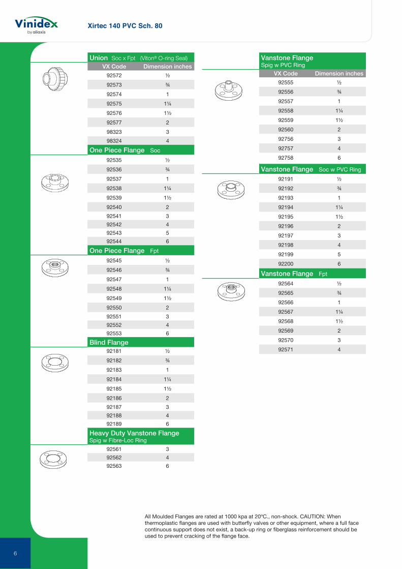
92572 ½92573 ¾92574 192575 1¼92576 1½92577 298323 398324 4
92535 ½92536 ¾92537 192538 1¼92539 1½92540 292541 392542 492543 592544 6
92545 ½92546 ¾92547 192548 1¼92549 1½92550 292551 392552 492553 6
92181 ½92182 ¾92183 192184 1¼92185 1½92186 292187 392188 492189 6
Union Soc x Fpt (Viton® O-ring Seal)
One Piece Flange Soc
One Piece Flange Fpt
Blind Flange
VX Code Dimension inchesVX Code Dimension inches
92561 392562 492563 6
92555 ½92556 ¾92557 192558 1¼92559 1½92560 292756 392757 492758 6
Heavy Duty Vanstone Flange Spig w Fibre-Loc Ring
Vanstone Flange Spig w PVC Ring
92191 ½92192 ¾92193 192194 1¼92195 1½92196 292197 392198 492199 592200 6
92564 ½92565 ¾92566 192567 1¼92568 1½92569 292570 392571 4
Vanstone Flange Soc w PVC Ring
Vanstone Flange Fpt
All Moulded Flanges are rated at 1000 kpa at 20ºC., non-shock. CAUTION: When thermoplastic flanges are used with butterfly valves or other equipment, where a full face continuous support does not exist, a back-up ring or fiberglass reinforcement should be used to prevent cracking of the flange face.
6

Xirtec 140 PVC Sch. 80
NipplesVX Code Dimension inches
¼” diameter
92578 7⁄8 close92586 1½92593 292594 2½92595 392596 3½92597 492598 4½92599 592600 698325 1098326 12
½” diameter
92579 11⁄8 close92587 1½92601 292602 2½92603 392604 3½92605 492606 4½92607 592608 5½92609 692610 892611 1092612 12
close
standard
close
standard
¾” diameter92588 1½92613 292614 2½92615 392616 3½92617 492618 4½92619 592620 5½92621 692622 892623 1092624 12
1” diameter
92580 1½ close92589 292625 2½92626 392627 3½92628 492629 4½92630 592631 5½92632 692633 892634 1092635 12
1¼” diameter92581 15⁄8 close92590 292636 2½92637 392638 3½92639 492640 4½92641 592642 692643 892644 1092645 12
NipplesVX Code Dimension inches
7
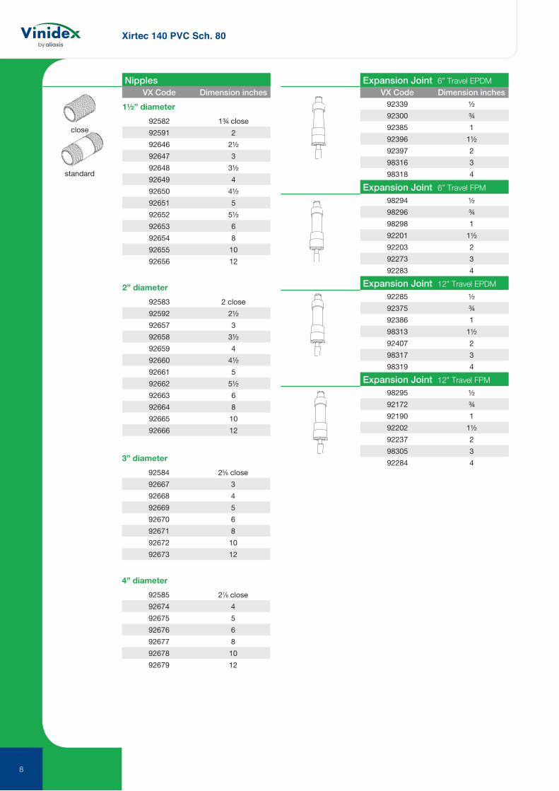
Xirtec 140 PVC Sch. 80
1½” diameter92582 1¾ close92591 292646 2½92647 392648 3½92649 492650 4½92651 592652 5½92653 692654 892655 1092656 12
2” diameter92583 2 close92592 2½92657 392658 3½92659 492660 4½92661 592662 5½92663 692664 892665 1092666 12
close
standard
NipplesVX Code Dimension inches VX Code Dimension inches
3” diameter92584 25⁄8 close92667 392668 492669 592670 692671 892672 1092673 12
4” diameter92585 27⁄8 close92674 492675 592676 692677 892678 1092679 12
Expansion Joint 6” Travel EPDM
Expansion Joint 6” Travel FPM
Expansion Joint 12” Travel EPDM
Expansion Joint 12” Travel FPM
92339 ½92300 ¾92385 192396 1½92397 298316 398318 4
98294 ½98296 ¾98298 192201 1½92203 292273 392283 4
92285 ½92375 ¾92386 198313 1½92407 298317 398319 4
98295 ½92172 ¾92190 192202 1½92237 298305 392284 4
8

Corzan CPVC Sch. 80
9
VX Code Dimension inches
Fabricated Tee Soc x Soc x Soc
Tee Soc x Soc x Soc
Tee Soc x Soc x Fpt
Tee Soc x Soc x Fpt
98169 ¼92487 ½92488 ¾92489 192490 1¼92491 1½92492 292493 392494 498170 6
98250 ½98251 ¾98191 192767 2
98182 ¼98183 ½98184 ¾98185 198186 1¼98187 1½98188 298189 398190 4
98171 ¾ x ¾ x ½98172 1 x 1 x ½98173 1 x 1 x ¾98216 1¼ x 1 x 198217 1¼ x 198174 1¼ x 1 x 1¼98218 1½ x 1¼ x 198175 1½ x 1½ x ¾92497 1½ x 1½ x 198176 2 x 2 x ½98177 2 x 2 x ¾92498 2 x 2 x 198178 2 x 2 x 1½98179 3 x 3 x 292499 4 x 4 x 298180 4 x 4 x 398219 6 x 6 x 398181 6 x 6 x 4
98024 ¼92398 ½92399 ¾92400 192401 1¼92402 1½92403 292404 392405 492406 6
98025 ¼98026 ½98027 ¾98028 198029 1¼98030 1½98031 298032 398033 4
98220 ¼98019 ½98249 ¾98020 198021 1¼98022 1½98023 2
90º Elbow Soc x Soc
90º Elbow Fpt x Fpt
90º Elbow Soc x Fpt
VX Code Dimension inches
45º Elbow Soc x Soc
45º Elbow Fpt x Fpt
22½º Elbow Soc x Soc
98009 ¼92387 ½92388 ¾92389 192390 1¼92391 1½92392 292393 392394 492395 6
98010 ¼98011 ½98012 ¾98013 198014 1¼98015 1½98016 298017 398018 4
98221 298222 398223 4
92355 ½92356 ¾92357 1 92358 1½92359 1¼92360 292361 392362 492363 6
CPVC Sch. 80 Pipe

Corzan CPVC Sch. 80
10
92778 ¼92376 ½92377 ¾92378 192379 1¼92380 1½92381 292382 392383 492384 6
92779 ¼92780 ½92781 ¾92782 192783 1¼92784 1½92785 292786 392787 4
Coupling Soc x Soc
VX Code Dimension inches
Coupling Fpt x Fpt
Reducer Coupling Soc x Soc92472 ¾ x ½92473 1 x ½92474 1 x ¾92475 1¼ x ½92476 1¼ x ¾92477 1¼ x 192478 1½ x ½92479 1½ x ¾92480 1½ x 192481 1½ x 1¼92482 2 x ¾92483 2 x 198228 2 x 1¼98166 2 x 1½98168 3 x 298167 4 x 292484 4 x 392485 6 x 4
VX Code Dimension inchesReducer Bushing Spig x Soc
98124 ½ x ¼92447 ¾ x ½92448 1 x ½92449 1 x ¾92450 1¼ x ½98125 1¼ x ¾92451 1¼ x 192452 1½ x ½92453 1½ x ¾92454 1½ x 192455 1½ x 1¼92456 2 x ½92457 2 x ¾92458 2 x 198126 2 x 1¼98127 2 x 1½98208 3 x 198229 3 x 1¼98128 3 x 1½98129 3 x 298131 4 x 298132 4 x 398133 6 x 298134 6 x 398135 6 x 4
11¼º Elbow Soc x Soc
Cross Soc x Soc x Soc x Soc
98224 298225 398226 4
98227 ¼92788 ¾92789 192790 1¼98005 1½98006 298007 398008 4
10

Corzan CPVC Sch. 80
11
98157 ½ x ¼98158 ¾ x ¼92459 ¾ x ½92460 1 x ½92461 1 x ¾92462 1¼ x ½92463 1¼ x ¾92464 1¼ x 192465 1½ x ½92466 1½ x ¾92467 1½ x 192468 1½ x 1¼92469 2 x ½92470 2 x ¾92471 2 x 198159 2 x 1¼98160 2 x 1½98230 3 x ¾98206 3 x 198231 3 x 1¼98161 3 x 1½98162 3 x 298163 4 x 298164 4 x 398233 6 x 398165 6 x 4
VX Code Dimension inchesReducer Bushing Spig x Fpt
Reducer Bushing Mpt x Fpt 98136 ½ x ¼98137 ¾ x ¼98138 ¾ x ½98234 1 x ¼98139 1 x ½98140 1 x ¾98141 1¼ x ½98142 1¼ x ¾98143 1¼ x 198144 1½ x ½98145 1½ x ¾98146 1½ x 198147 1½ x 1¼98148 2 x ½98149 2 x ¾98150 2 x 198151 2 x 1¼98152 2 x 1½98153 3 x 1½98154 3 x 298155 4 x 298156 4 x 3
Male Adapter Soc x Mpt
92439 ½92440 ¾92441 192442 1¼92443 1½92444 292445 392446 4
VX Code Dimension inches
Female Adapter Soc x Fpt98034 ¼92409 ½92410 ¾92411 192412 1¼92413 1½92414 292415 392416 4
Female AdapterSoc x Fpt (SS reinforced)
Female AdapterSpig x Fpt (SS reinforced)
98258 ½98259 ¾98260 198261 1¼98262 1½98263 298264 398265 4
98252 ½98253 ¾98254 198255 1¼98256 1½98257 298235 398236 4
92768 ¼92366 ½92367 ¾92368 192369 1¼92370 1½92371 292372 392373 492374 6
Cap Soc

Corzan CPVC Sch. 80
12
All Moulded Flanges are rated at 1000 kpa at 20ºC., non-shock. CAUTION: When thermoplastic flanges are used with butterfly valves or other equipment, where a full face continuous support does not exist, a back-up ring or fiberglass reinforcement should be used to prevent cracking of the flange face.
92769 ¼92770 ½92771 ¾92772 192773 1¼92774 1½92775 292776 392777 4
VX Code Dimension inches VX Code Dimension inches
Union Fpt x Fpt (EPDM O-ring Seal)
Union Soc x Soc (Viton® O-ring Seal)
Union Fpt x Fpt (Viton® O-ring Seal)
45º Wye Soc x Soc x Soc
Cap Fpt
Plug Mpt
Union Soc x Soc (EPDM O-ring Seal)
98115 ¼98116 ½98117 ¾98118 198119 1¼98120 1½98121 298122 398123 4
92508 ½92509 ¾92510 192511 1¼92512 1½92513 292514 392515 4
98215 ½98209 ¾98210 198211 1¼98212 1½98213 298214 398237 4
98192 ¼92500 ½92501 ¾92502 192503 1¼92504 1½92505 292506 392507 4
98193 ¼98194 ½98195 ¾98196 198197 1¼98198 1½98199 298200 398238 4
98239 ½98240 ¾98241 198242 1¼98207 1½98201 298202 398203 498204 698205 6 x 6 x 4
½” - 2” Wye – 1600 kpa maximum internal pressure rating @ 20ºC3” - 6 x 6 x 4” Wye – 1000 kpa maximum internal pressure rating @ 20ºC
One Piece Flange Soc
One Piece Flange Fpt
98035 ½98036 ¾98037 198038 1¼98039 1½98040 298041 398042 498043 6
98044 ½98045 ¾98046 198047 1¼98048 1½98049 298050 398051 4
12

Corzan CPVC Sch. 80
13
All Moulded Flanges are rated at 1000 kpa at 20ºC., non-shock. CAUTION: When thermoplastic flanges are used with butterfly valves or other equipment, where a full face continuous support does not exist, a back-up ring or fiberglass reinforcement should be used to prevent cracking of the flange face.
VX Code Dimension inches
Vanstone Flange Fpt
Heavy Duty Vanstone Flange Soc
92428 ½92429 ¾92430 192431 1¼92432 1½92433 292434 392435 492436 6
98243 ½98244 ¾98245 198061 1¼98246 1½98247 298062 398248 4
92417 ½92418 ¾92419 192420 1¼92421 1½92422 292423 392424 492425 6
98052 ½98053 ¾98054 198055 1¼98056 1½98057 298058 398059 498060 6
close
standard
Vanstone Flange Spig
Blind Flange
¼” diameter98063 7⁄8 close98071 1½98079 298080 398081 498082 598083 6
½” diameter98064 11⁄8 close98072 1½98085 298084 398086 498087 598088 6
¾” diameter98073 1½98089 298090 398091 498092 598093 6
1” diameter98065 1½ close98074 298094 398095 498096 598097 6
NipplesVX Code Dimension inches

Corzan CPVC Sch. 80
14
close
standard
1¼” diameter98066 15⁄8 close98075 298098 398099 498100 598101 6
1½” diameter98067 1¾ close98076 298102 398103 498104 598105 6
2” diameter98068 2 close98077 2½98106 398107 498108 598109 6
3” diameter98069 25⁄8 close98110 398111 498112 598113 6
4” diameter98070 27⁄8 close98078 492766 598114 6
Nipples Expansion Joint 6” Travel EPDM
Expansion Joint 12” Travel EPDM
Expansion Joint 6” Travel FPM
Expansion Joint 12” Travel FPM
VX Code Dimension inches VX Code Dimension inches98280 ½98282 ¾98284 198286 1½98288 298290 398292 4
98281 ½98283 ¾98285 198287 1½98289 298291 398293 4
98266 ½98268 ¾98270 198272 1½98274 298276 398278 4
98267 ½98269 ¾98271 198273 1½98275 298277 398279 4

15

SuperFLO ABS
16
SuperFLO ABS Pipe imperial system Plain
d1 (mean)
t (mean)
Mean OD Thickness Length Weight Code Size d1 t (mm) (m) kg/m 3/8 17.1 1.7 6 0.09 90760 ½ 21.4 2.0 6 0.13 90761 ¾ 26.7 2.5 6 0.20 90762 1 33.6 3.1 6 0.31 90763 1¼ 42.2 3.9 6 0.49 90764 1½ 48.3 4.5 6 0.64 90765 2 60.3 5.6 6 1.00 90766 3 88.9 8.3 6 2.16 90767 4 114.3 10.6 6 3.59 90768
Mean OD Thickness Length Weight Code Size d1 t (mm) (m) kg/m 6 168.3 9.9 6 5.12 90769 8 219.1 12.7 6 8.57 90770
Mean OD Thickness Length Weight Code Size d1 t (mm) (m) kg/m 3/8 17.1 3.5 6 0.16 90807 ½ 21.4 3.6 6 0.22 90808 ¾ 26.7 3.6 6 0.28 90809 1 33.6 4.3 6 0.43 90810 1¼ 42.2 5.3 6 0.65 90811 1½ 48.3 6.0 6 0.85 90812 2 60.3 7.2 6 1.28 90813
Pipe - ABS Class T (for threading) 173 psig (12 bar after threading)
Pipe - ABS Class E 217psig (15 bar)
Pipe - ABS Class C130psig (9 bar)

SuperFLO ABS
17
Sockets Plain
B
Z1
A
Size PN A B Z1 gms Code 3/8 15 21 32 2 4 90466 ½ 15 26 38 2 6 90467 ¾ 15 32 43 3 12 90468 1 15 41 50 3 24 90469 1¼ 15 52 60 4 41 90470 1½ 15 60 66 2 62 90471 2 15 74 78 4 114 90472 3 15 108 104 4 355 90473 4 15 136 135 5 595 90474 6 12 201 191 9 2269 90475 8 9 257 249 11 3668 90476
Reducing bushes Plain
BZ1
Size PN B Z1 gms Code½ x 3/8 15 17 2 7 90510¾ x ½ 15 20 3 8 905111 x ½ 15 23 6 23 905121 x ¾ 15 24 4 15 90513
*1¼ x ½ 15 28 12 21 90505*1¼ x ¾ 15 28 8 24 905061¼ x 1 15 28 5 20 90514*1½ x ½ 15 30 13 26 90507*1½ x ¾ 15 30 10 37 90508*1½ x 1 15 30 7 40 905151½ x 1¼ 15 31 4 19 90516*2 x ¾ 15 38 15 45 90509*2 x 1 15 38 15 45 90517
*2 x 1¼ 15 38 11 57 905182 x 1½ 15 37 7 42 90519*3 x 1½ 15 51 21 130 90521*3 x 2 15 51 15 178 90522*4 x 3 15 65 12 277 90524*6 x 4 12 93 27 666 90525*8 x 6 9 110 23 1185 90526
*Relief configuration (see drawing insert).
BZ1
BZ1
*

SuperFLO ABS
18
Elbows 45° Plain
Elbows 90° Plain
Z1
A
C
Size PN A C Z1 gms Code 3/8 15 21 20 6 8 90571 ½ 15 27 26 8 9 90572 ¾ 15 33 27 12 15 90573 1 15 41 37 13 25 90574 1¼ 15 52 44 15 59 90575 1½ 15 60 50 18 86 90576 2 15 82 66 27 160 90577 3 15 112 94 40 750 90578 4 15 139 115 50 1300 90579 6 12 198 134 41 2390 90580 8 9 259 182 65 5620 90581
Size PN A C Z1 gms Code 3/8 15 21 24 9 6 90542 ½ 15 26 29 12 11 90543 ¾ 15 32 34 14 19 90544 1 15 41 41 17 35 90545 1¼ 15 52 49 21 70 90546 1½ 15 60 56 26 101 90547 2 15 74 68 31 191 90548 3 15 111 104 52 720 90549 4 15 141 130 65 1505 90550 6 12 203 175 85 4075 90551 8 9 256 251 112 6900 90552
A
Z1
C
B
A
Z1
C
Reducing sockets Plain Size PN A B C Z1 gms Code ¾ x ½ 15 32 44 26 7 11 90533 1 x ¾ 15 41 53 33 9 19 90534 1¼ x 1 15 52 63 41 10 39 90535 1½ x 1¼ 15 59 68 51 8 58 90536 2 x 1½ 15 74 82 59 12 100 90537 3 x 2 15 108 114 75 26 320 90538 4 x 3 15 136 136 108 20 558 90539 6 x 4 12 205 213 140 55 1975 90540 8 x 6 9 256 263 198 50 3410 90541
B
A
Z1
Z3
C
Z2
Tees 45° Plain Size PN A B C Z1 Z2 Z3 gms Code ½ 9 28 68 44 34 27 7 30 90597 ¾ 9 33 81 52 41 32 8 45 90598 1 9 41 97 63 49 39 9 80 90599 1¼ 9 50 117 80 61 52 10 194 90600 1½ 9 60 140 97 80 67 12 298 90601 2 9 74 170 113 90 73 15 546 90602

SuperFLO ABS
19
C
Z1
BAZ1
Tees 90° Equal plain Size PN A B C Z1 gms Code 3/8 15 21 49 25 10 7 90582 ½ 15 26 58 29 11 13 90583 ¾ 15 32 69 34 15 23 90584 1 15 41 83 42 19 43 90585 1¼ 15 52 101 50 23 92 90586 1½ 15 59 113 53 25 133 90587 2 15 74 137 70 31 249 90588 3 15 113 204 105 44 926 90589 4 15 143 244 121 54 1960 90590 6 12 205 355 175 88 4449 90591 8 9 257 468 240 100 9600 90592
C
Z1
D
A
Z3
Z2B
Tees 90° Swept plain Size PN A B C D Z1 Z2 Z3 gms Code 1 9 41 115 79 79 57 57 14 85 90650 1½ 9 62 160 105 105 74 74 24 285 90651 2 9 78 195 125 125 87 87 32 515 90652 4 9 139 315 190 190 127 127 62 2080 90654
Bends 221⁄2° Long radius Size PN C E R gms Code 1 15 76 38 102 46 90719 1½ 15 110 57 152 143 90720 2 15 113 73 203 274 90721 3 15 202 114 305 857 90722 4 15 262 152 407 1886 90723 6 12 385 229 610 5154 90724 8 9 503 305 812 8962 90725
Tolerance on angle ±3°
R
C
E

SuperFLO ABS
20
Bends 45° Long radiusC
R
E
Size PN C E R gms Code 1 15 75 37 102 51 90712 1½ 15 113 55 152 156 90713 2 15 152 73 203 322 90714 3 15 238 121 305 1100 90715 4 15 300 145 407 2290 90716 6 12 440 218 610 6290 90717 8 9 592 280 812 11440 90718
Tolerance on angle ±3°
Bends 90° Long radius
CR
E
Size PN C E R gms Code 3 15 403 98 305 1535 90708 4 15 545 138 407 3440 90709 6 12 817 207 610 9430 90710 8 9 1174 362 812 19070 90711Tolerance on angle ±3°
Bends 90° Short radius plain
Z1
C
A
Size PN A C Z1 gms Code
½ 15 26 56 43 20 90563 ¾ 15 33 65 45 45 90564 1 15 40 85 63 65 90565 1¼ 15 51 108 81 130 90566 1½ 15 62 134 102 290 90567 2 15 73 165 126 560 90568 3 15 111 226 172 1445 90569 4 15 140 280 216 2400 90570
B
E
AZ1
pipecentre
line
Saddles Plain Size PN A B E Z1 gms Code 2 x 1¼ 15 60 136 48 33 90 90593 3 x 1½ 15 76 140 60 46 158 90594 4 x 2 15 95 140 74 58 230 90595 6 x 2 15 71 154 73 86 225 90596
Two saddles can be mounted diametrically opposite.

SuperFLO ABS
21
End caps Plain
Socket unions Plain
B
Z2Z1
A
Size PN A B gms Fig Code 3/8 15 21 17 3 1 90633 ½ 15 26 22 5 1 90634 ¾ 15 32 25 9 1 90635 1 15 40 30 20 1 90636 1¼ 15 52 51 33 2 90637 1½ 15 59 39 48 1 90638 2 15 74 70 90 2 90639 3 15 109 97 268 2 90640 4 15 136 120 465 2 90641
Size PN A B Z1 Z2 gms Code 3/8 15 39 44 5 10 25 90685 ½ 15 43 49 5 10 36 90686 ¾ 15 51 55 5 10 51 90687 1 15 64 65 7 12 86 90688 1¼ 15 72 77 10 14 122 90689 1½ 15 79 92 13 16 160 90690 2 15 102 112 15 19 297 90691 3 9 155 113 6 4 750 90692 4 9 180 138 7 6 1155 90693
EPDM seal as standard.For FPM seal order 01 204 1**
FIG.1
FIG.2
B
A
B
A

SuperFLO ABS
22
BZ1
Reducing bushes Plain female BSP thread Size PN B Z1 gms Code ½ x 3/8 12 17 6 4 90527 3/8 x ½ 12 20 5 7 90528 1 x ¾ 12 23 6 12 90529
A
Z1
C
Z1
Elbows 90° Plain female BSP thread Size PN A C Z1 gms Code ½ 12 26 34 17 26 90553 ¾ 12 32 36 20 34 90554 1 12 40 41 23 63 90555 1½ 12 62 57 30 136 90556 2 12 75 66 35 203 90557
BC
Z1
A
Sockets Plain female BSP thread Size PN A B C Z1 gms Code ½ 12 27 38 17 4 8 90477 ¾ 12 33 44 20 2 14 90478 1 12 42 51 23 5 30 90479 1¼ 12 52 55 22 4 46 90480 1½ 12 60 61 26 2 65 90481 2 12 75 70 29 2 114 90482 3 12 110 107 52 3 378 90483
Female threaded adaptors Plain spigot end/female BSP thread Size PN A B Z1 gms Code ½ 12 27 38 16 8 90662 ¾ 12 36 44 18 14 90663 1 12 43 50 21 24 90664 1¼ 12 55 60 22 49 90665 1½ 12 63 66 25 68 90666 2 12 78 78 29 129 90667Z1
B
A

SuperFLO ABS
23
Hexagon nipples Plain spigot/male BSP thread Size PN A B D gms Code 3/8 12 24 36 11 7 90498 ½ 12 30 42 15 12 90499 ¾ 12 36 48 16 30 90500 1 12 46 56 20 40 90501 1¼ 12 46 60 21 50 90502 1½ 12 55 63 22 58 90503 2 12 72 74 26 91 90504
B
D
A(A/F)
Male threaded adaptors Plain/male BSP taper threaded Size PN A B D Z1 gms Code
3/8 12 22 35 10 20 5 90655 ½ 12 27 45 12 28 9 90656 ¾ 12 35 48 14 28 14 90657
Z1
B
A
D
B
Z1
D
A(A/F)
Size PN A B D Z1 gms Code 1 12 46 58 19 35 36 90658 1¼ 12 56 66 22 38 70 90659 1½ 12 72 75 22 43 115 90660 2 12 80 85 26 46 150 90661
Barrel nipples Plain/BSP taper threaded Size PN B D gms Code 3 12 128 30 252 90731 4 12 153 36 525 90732
B
D

SuperFLO ABS
24
Z1
A(A/F)
B
Z2
B
Z1
A(A/F)
B D
A(A/F)
C
E
B
D
A(A/F) F C
Composite unions Plain/brass, female BSP parallel thread
Composite unions Plain/brass, male BSP taper thread
Hose adaptors BSP taper threaded/hose tail Size PN A B C D E gms Code ½ 12 26 60 41 13 14 8 90675 ¾ 12 28 66 41 16 20 15 90676 1 12 40 73 46 19 27 28 90677
Tank connectors Plain spigot/male BSP parallel thread Size A B C D F gms Code ½ 28 70 38 28 15 26 90706 ¾ 33 77 38 38 21 30 90707
Size PN A B Z1 Z2 gms Code ½ 15 40 42 3 7 165 90694 ¾ 15 48 49 3 9 290 90695 1 15 55 59 11 12 310 90696 1¼ 15 65 68 9 10 450 90697 1½ 15 79 75 12 14 800 90698 2 15 88 90 14 14 950 90699
Fitted with brass retaining nut.
Brass material to BS2872, WRAS approved.
ALL Durapipe Brass Components are manufactured using DZR Brass.
Size PN A B Z1 gms Code ½ 15 40 54 3 175 90700 ¾ 15 48 74 3 320 90701 1 15 55 86 8 420 90702 1¼ 15 65 94 10 620 90703 1½ 15 78 108 13 1000 90704 2 15 88 129 15 1200 90705
Fitted with brass retaining nut.
Brass material to BS2872, WRAS approved.
ALL Durapipe Brass Components are manufactured using DZR Brass.

SuperFLO ABS
25
B
A
Sockets Female BSP taper thread
A
Z1
C
Elbows 90° Female BSP taper thread
B
D
A(A/F)
Reducing bushes Male/female BSP thread
B
A
D
End caps Female BSP taper thread
Size PN A B gms Code ½ 12 26 38 12 90484 ¾ 12 33 43 22 90485 1 12 41 51 34 90486 1¼ 12 51 54 60 90487 1½ 12 62 63 87 90488 2 12 75 72 132 90489 3 12 110 107 437 90490
Size PN A C Z1 gms Code ½ 12 26 29 17 27 90558 ¾ 12 32 33 19 39 90559 1 12 41 41 23 65 90560 1½ 12 63 57 30 141 90561 2 12 75 67 35 212 90562
Size PN A B D gms Code ½ x 3/8 12 24 25 10 5 90530 ¾ x ½ 12 30 27 11 10 90531 1 x ¾ 12 36 31 12 13 90532
Male thread taper.
Female thread parallel.
Size PN A B D gms Code 3/8 12 26 20 16 5 90642 ½ 12 27 20 16 6 90643 ¾ 12 36 23 17 10 90644 1 12 44 28 21 18 90645 1¼ 12 55 31 22 33 90646 1½ 12 63 35 25 50 90647 2 12 78 40 28 90 90648 3 12 111 65 53 262 90649

SuperFLO ABS
26
B
A(A/F)C
Back nuts Female BSP taper thread Size PN A B C gms Code 3/8 12 25 11 29 5 90678 ½ 12 28 13 38 8 90679 ¾ 12 33 13 38 15 90680 1 12 45 16 54 18 90681 1¼ 12 50 18 58 19 90682 1½ 12 60 19 69 31 90683 2 12 79 21 91 65 90684
Flanges stub Plain/serrated Size PN A B D Z1 gms Code 2 15 96 40 14 3 90 90628 3 15 127 57 18 6 200 90629 4 15 159 69 20 6 350 90630 6 12 213 104 24 11 805 90631 8 9 269 132 26 14 2075 90632
B
D
A(A/F)
Plugs Male BSP taper thread Size PN A B D gms Code 3/8 12 11 19 10 3 90668 ½ 12 13 23 14 5 90669 ¾ 12 14 28 15 8 90670 1 12 17 30 17 12 90671 1¼ 12 22 35 22 30 90672 1½ 12 27 38 22 36 90673 2 12 37 45 26 50 90674
B
D
A(A/F)
Hexagon nipples Male BSP taper thread Size PN A B D gms Code 3/8 12 24 38 14 6 90491 ½ 12 30 46 18 12 90492 ¾ 12 36 50 19 30 90493 1 12 46 59 13 40 90494 1¼ 12 46 67 27 55 90495 1½ 12 55 73 29 75 90496 2 12 72 81 33 125 90497
B
D
Z1
A
All Durapipe flanges are designed for use with Durapipe backing rings. Guarantees are null and void if used with incorrect backing ring.

SuperFLO ABS
27All Durapipe flanges are designed for use with Durapipe backing rings. Guarantees are null and void if used with incorrect backing ring.
Flanges full face Plain/drilled
Note: Durapipe backing rings must be used in conjunction with full face flanges.
A
Z1
D B
BS10 Table D/E No. of Hole Size A B D Z1 P.C.D. Holes Diameter gms Code ½ 96 21 10 4 67 4 14 68 90612 ¾ 105 24 10 4 73 4 14 78 90613 1 115 27 10 4 83 4 14 107 90614 1¼ 140 33 10 5 87 4 14 122 90615 1½ 150 37 10 5 98 4 14 154 90616 2 166 45 10 6 115 4 18 223 90617 3 199 60 11 8 145 4 18 398 90618 *4 220 72 14 6 178 8 18 638 90619 6 284 98 22 8 235 8 22 1340 90620
*4” BS10 Table D has 4 holes and should be ordered as 01 317 110.
No. of Hole Size A B D Z1 P.C.D. Holes Diameter gms Code ½ 96 21 10 4 65 4 14 68 90733 ¾ 105 24 10 4 75 4 14 78 90734 1 115 27 10 4 85 4 14 107 90735 11⁄4 140 33 10 5 100 4 18 122 90736 11⁄2 150 37 10 5 110 4 18 154 90737 2 166 45 10 6 125 4 18 223 90738 3 199 60 11 8 160 8 18 398 90739 4 220 72 14 6 180 8 18 638 90740 6 284 98 22 8 240 8 22 1340 90741
No. of Hole Size A B D Z1 P.C.D. Holes Diameter gms Code ½ 96 21 10 4 60 4 14 68 90742 ¾ 105 24 10 4 70 4 14 78 90743 1 115 27 10 4 80 4 14 107 90744 1½ 150 37 10 5 98 4 14 154 90745 2 166 45 10 6 121 4 18 223 90746 3 199 60 11 8 152 4 18 398 90747 4 220 72 14 6 190 8 18 638 90748 6 284 98 22 8 241 8 22 1340 90749
Size PN A B D Z1 gms Code ½ 15 96 21 10 4 75 90603 ¾ 15 105 24 10 4 85 90604 1 15 115 27 10 4 111 90605 1¼ 15 140 32 10 4 130 90606 1½ 15 150 36 10 5 160 90607 2 15 165 45 11 6 233 90608 3 15 199 60 11 8 414 90609 4 15 220 73 14 6 657 90610 6 12 284 99 22 8 1417 90611
Undrilled
BS4504 Table 16/3-10/3
ANSI Class 150

SuperFLO ABS
28
ANSI Class 150 No. of Hole Size A B P.C.D. Holes Diameter gms Code 2 165 13 121 4 18 235 90755 3 197 19 152 4 18 520 90756 4 214 19 190 8 18 720 90757 6 286 26 241 8 22 1575 90758 8 337 26 298 8 22 2300 90759
B
A
BS10 Table D/E No. of Hole Size A B P.C.D. Holes Diameter gms Code 2 165 13 115 4 18 235 90726 3 197 19 145 4 18 520 90727 *4 214 19 178 8 18 720 90728 6 286 26 235 8 22 1575 90729 8 337 26 292 8 22 2300 90730
*4” BS10 Table D has 4 holes and should be ordered as 01 326 110.
Flanges blanking Plain/drilled
Backing rings Galvanised mild steel drilled
Size PN A B gms Code 1 15 116 13 140 90621 1½ 15 150 13 185 90622 2 15 166 13 235 90623 3 15 197 19 520 90624 4 15 214 19 720 90625 6 12 286 26 1575 90626 8 9 337 26 2300 90627
Note: Durapipe backing rings must be used in conjunction with blank flanges.
Undrilled
BS4504 Table 16/3 (½” to 8”) 10/3 (½” to 6”) No. of Hole Size A B P.C.D. Holes Diameter gms Code 2 165 13 125 4 18 235 90750 3 197 19 160 8 18 520 90751 4 214 19 180 8 18 720 90752 6 286 26 240 8 22 1575 90753 8 337 26 295 12 22 2300 90754
B
AC P
L
BS10 Table D/E No. of Hole Bolt Weight Size A B C P Holes Dia. Size gms Code ½ 95 6 35 67 4 14 M12x50 270 90836 ¾ 103 7 45 73 4 14 M12x50 300 90837 1 114 6 49 83 4 14 M12x50 380 90838 1¼ 120 7 60 87 4 14 M12x50 380 90839 1½ 135 7 68 98 4 14 M12x50 480 90840 2 151 8 78 115 4 18 M16x65 880 90841 3 187 9 110 145 4 18 M16x70 1040 90842 *4 216 9 140 178 8 18 M16x80 1330 90843 6 282 11 195 235 8 22 M20x90 2340 90845 8 337 10 255 292 8 22 M20x100 2870 90846*4” BS10 Table D has 4 holes and should be ordered as 03 415 110.
All Durapipe flanges are designed for use with Durapipe backing rings. Guarantees are null and void if used with incorrect backing ring.

SuperFLO ABS
29
VKD Double union ball valves Manual – EPDM seals
Options: FPM seals (plain ends) order H0 DKB*** FPM seals (threaded ends) order H0 DKB***
Manual valves can be supplied with locking kits - further information is available from our Valve Department.
d DN PN L Z H E B C gms Code ½ 15 16 16.5 70 103 55 49 66 160 90771 ¾ 20 16 19 77 115 66 59 75 265 90772 1 25 16 22.5 83 128 75 66 85 345 90773 1¼ 32 16 26 94 146 87 75 97 550 90774 1½ 40 16 30 104 164 100 87 110 730 90775 2 50 16 36 127 199 122 101 134 1280 90776
d DN PN Z L H H1 E B B1 C C1 gms Code
3 80 16 168 51 270 149 203 177 105 327 272 5700 90777 4 100 16 186 61 308 167 238 195 129 385 330 8660 90778
Options: FPM seals (plain ends) order H0 DKB***
VKD & TKD ball valves can be supplied electrically or pneumatically actuated.
SX Easyfit ball check valves Plain ends – EPDM seals (other options available)
Options: EPDM seals (threaded ends) order H0 SXA B** FPM seals (plain ends) order H0 SXB*** FPM seals (threaded ends) order H0 SXB B**
Note: this valve must be installed at a minimum distance of 10 x nominal diameter (eg. 20" for size 2") from pump flange.
d DN PN L Z H E gms Code ½ 15 16 16.5 50 82 54 133 90781 ¾ 20 16 19 53 91 63 171 90782 1 25 16 22.5 59 103 72 270 90783 1¼ 32 16 26 68 120 85 414 90784 1½ 40 16 30 77 139 100 608 90785 2 50 16 36 98 174 118 972 90786

SuperFLO ABS
30
RV Y-Type strainers Plain ends – EPDM seals
Options: EPDM seals (threaded ends) order H0 RVA B** FPM seals (plain ends) order H0 RVB*** FPM seals (threaded ends) order H0 RVB B**
d DN PN A B E L Z H Fig. gms Code Grey max ½ 15 15 125 72 55 16 103 135 A 211 90787 ¾ 20 15 145 84 66 19 120 158 A 358 90788 1 25 15 165 95 75 22 132 176 A 526 90789 1¼ 32 15 190 111 87 26 155 207 A 733 90790 1½ 40 15 210 120 100 31 181 243 A 1095 90791 2 50 9 240 139 120 38 222 298 A 1843 90792
DK Diaphragm valves Manual – plain union ends – EPDM seals
Options: FPM diaphragm order H0 VMB*** PTFE diaphragm order H0 VMC***
d DN PN B B1 H h H1 J L gms Code ½ 15 9 95 26 124 12 90 M6 16 690 90917 ¾ 20 9 95 26 144 12 90 M6 19 690 90918 1 25 9 95 26 154 12 90 M6 23 720 90919 1¼ 32 9 126 40 174 18 115 M8 27 1520 90920 1½ 40 9 126 40 194 18 115 M8 32 1545 90921 2 50 9 148 40 224 18 140 M8 39 2275 90922
*Note: 2½", 3" and 4" are spigot ended.
Size DN PN B2 B3 C C1 Z gms U Code
6 150 9 134 225 330 110 70 3850 8 90779 8 200 9 161 272 420 122 71 6750 8 90780
FK Butterfly valves Glass reinforced polypropylene with ABS disc and EPDM seals
Lever operated
Options: FPM seals order H0 FKB*** U = No. of holes
Note: Lugged versions available to special order. Please refer to our Valve Department for further details.

SuperFLO ABS
31
BG
C
A
D
Cobra pipe clips Polypropylene
Size A B C D G Bolt/Screw size gms Code 3/8 – 35 25 19 16 M.4/3BA/No 8 7 98327 ½ – 35 30 14 16 M.5/1BA/No 10 8 92346 ¾ – 35 35 16 17 M.5/1BA/No 10 11 92347 1 – 40 40 17 17 M.5/1BA/No 10 14 92348 1¼ 75 45 45 20 20 M.5/1BA/No 10 21 92349 1½ 85 50 50 22 21 M.6/0BA/No 10 30 92350 2 102 60 60 19 21 M.6/0BA/No 10 42 92351 3 148 80 90 39 31 M.8 121 92352 4 171 90 96 36 35 M.8 185 92353 6 243 170 150 40 40 M.8 330 92354
Clips of size 1¼" and above are fitted with retaining strap. Bolts/screws not supplied.
G E
C
F
Saddle clips Polypropylene Size C E F G Bolt/Screw size gms Code 3/8 13 37 – 14 M.4/3BA/No 8 3 90793 ½ 18 41 – 14 M.4/3BA/No 8 4 90794 ¾ 21 45 – 16 M.5/2BA/No 10 6 90795 1 23 56 – 16 M.5/2BA/No 10 7 90796 1¼ 29 65 – 16 M.5/2BA/No 10 11 90797 1½ 34 67 – 16 M.5/2BA/No 10 12 90798 2 38 87 – 22 M.6/0BA/No 12 25 90799 3 50 122 8 34 M.10/3⁄8UNC 45 90800 4 65 156 13 38 M.10/3⁄8UNC 70 90801
Backing plate shown dotted supplied with 3" and 4" only. Bolts/screws not supplied. Bolt holes in 3" and 4" clips are not countersunk.
One-step solvent cement
Only Durapipe ABS solvent cement and Durapipe MEK cleaner should be used for jointing of Durapipe ABS pipework systems.
ECO Cleaner Litres gms Code
0.5 500 90853
Only Durapipe ABS solvent cement and Durapipe ECO cleaner should be used for jointing of Durapipe ABS pipework systems.
Litres gms Code
0.5 550 90802 1.0 1100 90803

SuperFLO ABS
32
SuperFLO ABS Jointing GuideSolvent cement welding offers a simple and quick means of constructing high integrity, leak-free joints. The solvent cement operates by chemically softening the joint surfaces. Joint integrity will be greatly reduced if these surfaces are not clean and properly prepared.Durapipe SuperFLO ABS solvent cement must be used. The jointing procedure detailed below must be followed.When using ‘One-step’ solvent cement, it is not necessary to abrade pipe or fitting (unless making a joint on to old ABS pipe).No attempt should be made to increase the clearance between the pipes and fittings.
Procedure1. The pipe must be cut clean and square. A suitable wheel
cutter will eliminate swarf. As an alternative (and on larger sizes) a carpenters saw should be used, however this may create dust and swarf which can enter the system.
2. Chamfer the end of the pipe using a coarse file or suitable chamfering tool. The chamfer should be approximately 45° by 3mm to 5mm depending on the pipe size. Reducing bushes should also be chamfered (unless where a moulded chamfer is included).
3. Mark the pipe a known distance from the end and clear of the area to be cleaned. This mark should be used to confirm full insertion of pipe into socket of fitting.
4. Ensure joint surfaces are clean and free from moisture. Clean surfaces thoroughly with Durapipe MEK Cleaner
using lint free cloth/paper towel.
5. Using a clean brush apply cement to the pipe and fitting. The joint surfaces should be completely covered by cement.
Cement should be applied using an appropriate size brush and tin of cement. It is important to apply cement quickly to enable assembly without excessive force being required.
When applying cement with brush, the size of the brush should be approximately half the size of the pipe to be jointed - brush size up to 2½" (63mm) for 0.5 litre and up to 3" (75mm) for 1 litre tins.
6. Immediately after applications of cement, push pipe fully home into the fitting. Do not twist. Hold the pipe and the fitting for times varying from a few seconds on sizes 3/8" or 16mm up to 1 minute on size 315mm. The slight taper moulded into the fitting may otherwise cause it to slide off the pipe with consequent loss of joint strength. Application of the correct amount of cement will result in a neat bead of cement at the edge of the fitting and at the edge of the pipe. Excessive deposits inside the fittings must be avoided as these can weaken the wall, particularly on smaller sizes. When working under cold conditions make sure the joints are free from frost and moisture.
SuperFLO ABS
33
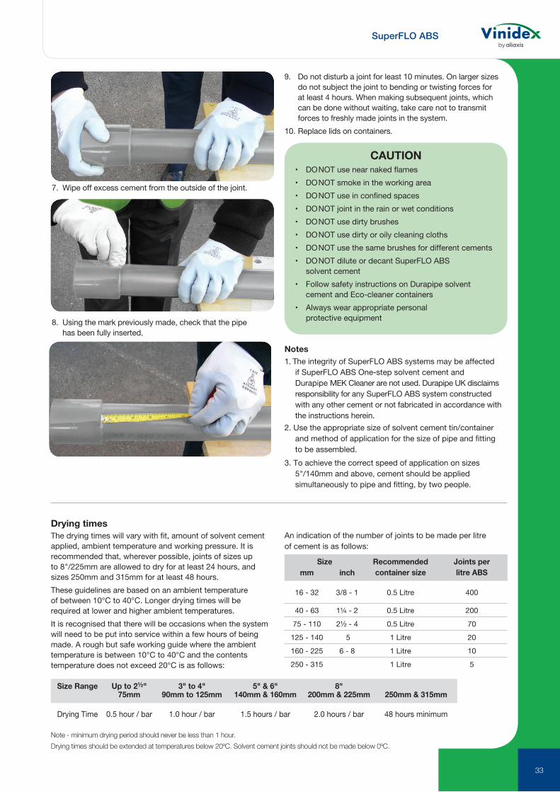
7. Wipe off excess cement from the outside of the joint.
8. Using the mark previously made, check that the pipe has been fully inserted.
Notes1. The integrity of SuperFLO ABS systems may be affected
if SuperFLO ABS One-step solvent cement and Durapipe MEK Cleaner are not used. Durapipe UK disclaims responsibility for any SuperFLO ABS system constructed with any other cement or not fabricated in accordance with the instructions herein.
2. Use the appropriate size of solvent cement tin/container and method of application for the size of pipe and fitting to be assembled.
3. To achieve the correct speed of application on sizes 5"/140mm and above, cement should be applied simultaneously to pipe and fitting, by two people.
Note - minimum drying period should never be less than 1 hour.
Drying times should be extended at temperatures below 20ºC. Solvent cement joints should not be made below 0ºC.
Size Range Up to 2½" 3" to 4" 5" & 6" 8" 75mm 90mm to 125mm 140mm & 160mm 200mm & 225mm 250mm & 315mm
Drying Time 0.5 hour / bar 1.0 hour / bar 1.5 hours / bar 2.0 hours / bar 48 hours minimum
Drying timesThe drying times will vary with fit, amount of solvent cement applied, ambient temperature and working pressure. It is recommended that, wherever possible, joints of sizes up to 8"/225mm are allowed to dry for at least 24 hours, and sizes 250mm and 315mm for at least 48 hours. These guidelines are based on an ambient temperature of between 10°C to 40°C. Longer drying times will be required at lower and higher ambient temperatures.It is recognised that there will be occasions when the system will need to be put into service within a few hours of being made. A rough but safe working guide where the ambient temperature is between 10°C to 40°C and the contents temperature does not exceed 20°C is as follows:
An indication of the number of joints to be made per litre of cement is as follows:
9. Do not disturb a joint for least 10 minutes. On larger sizes do not subject the joint to bending or twisting forces for at least 4 hours. When making subsequent joints, which can be done without waiting, take care not to transmit forces to freshly made joints in the system.
10. Replace lids on containers.
CAUTION• DO NOT use near naked flames• DO NOT smoke in the working area• DO NOT use in confined spaces• DO NOT joint in the rain or wet conditions• DO NOT use dirty brushes• DO NOT use dirty or oily cleaning cloths• DO NOT use the same brushes for different cements• DO NOT dilute or decant SuperFLO ABS
solvent cement• Follow safety instructions on Durapipe solvent
cement and Eco-cleaner containers• Always wear appropriate personal
protective equipment
Size Recommended container size
Joints per litre ABSmm inch
16 - 32 3/8 - 1 0.5 Litre 400
40 - 63 1¼ - 2 0.5 Litre 200
75 - 110 2½ - 4 0.5 Litre 70
125 - 140 5 1 Litre 20
160 - 225 6 - 8 1 Litre 10
250 - 315 1 Litre 5

SuperFLO ABS
34
Chemical resistanceand performance data
Typical applications
Unsuitable for the following uses
Sizes and jointinginformation
Moderately strong mineral acids Chilled water Applications over 60ºC Metric: 16mm to 315mm ODCaustic and ammoniacal solutions Low temperature brine Bleaches Imperial: 3/8" to 8" NBMost inorganic salt solutions Potable water Solvents Jointed by solvent cement
weldingSome detergents Process water Domestic hot water Threaded fittings availableTemperature range -40ºC to +60ºC Flammable substances
Note: Temperatures given are for guidance only, please check before specifying.
Properties guide
Tabulated below is a comparison of imperial and metric sized SuperFLO ABS pipe. They are produced to different standards, but can be joined together using flanges or adaptors.
The systems are also designated differently; the imperial system refers to the nominal bore size; the metric system relates to the outside diameter.
Both systems are produced with the outside diameter as the controlled dimension. This enables the same fitting of a particular size to be joined to all classes of pipe in that size.
Please refer to the pipe section in this brochure for pipe sizes available from Durapipe UK.
Threaded systems Imperial system Class T ABS pipe can be machined to BSP parallel or BSP taper thread forms. Metric pipe is not produced with an outside diameter suitable for threading.
Comparison of SuperFLO ABS Imperial and Metric Sized Pipe
Imperial System (BS 5391) Metric System (ISO 15493)Size
(nominal bore) (imperial)
Minimum mean outside diameter (mm)
Minimum wall thickness (mm)Size outside
diameter (mm)Minimum
mean outside diameter (mm)
Minimum wall thickness
(mm) PN10Class
BClass
CClass
DClass
EClass
T3/8 17.0 - - - 1.6 3.4 16 16.0 1.4½ 21.2 - - - 1.9 3.5 20 20.0 1.5¾ 26.6 - - - 2.4 3.5 25 25.0 1.8
1 33.4 - 1.9 - 3.0 4.2 32 32.0 2.0
1¼ 42.1 - 2.4 - 3.8 5.1 40 40.0 2.5
1½ 48.1 - 2.7 - 4.4 5.8 50 50.0 3.2
2 60.2 - 3.4 - 5.4 7.0 63 63.0 4.0
2½ 75.0 - 4.7 - - - 75 75.0 4.7
3 88.7 - 5.0 - 8.06 - 90 90.0 5.7
4 114.1 - 6.4 - 10.3 - 110 110.0 6.9
- - - - - - - 125 125.0 7.9
5 140.0 - 8.8 - - - 140 140.0 8.8
6 168.0 - 9.4 12.3 - - 160 160.0 10.0
- - - - - - - 200 200.0 12.5
8 218.0 - 12.2 - - - 225 225.0 14.1
- - - - - - - 250 250.0 15.6
- - - - - - - 315 315.0 19.7*
2½” and 5” pipes are PN10 rated. *315mm is rated at PN8.
DURAPIPE UK MANUFACTURE FULLY MATCHED PIPEWORK SYSTEMS.AS A RESULT WE DO NOT RECOMMEND THE USE OF NON-DURAPIPE PRODUCTS
INCLUDING BACKING RINGS, GASKETS, SOLVENT CEMENT AND CLEANER. INSIST ON DURAPIPE.

35

Thermoplastic Valves
Vinidex offers one of the most comprehensive ranges of high quality, high performance thermoplastic valves and actuation products available today. With more than 65 years of design and manufacturing experience, FIP lightweight, long life, maintenance free valves will save you time and money.
36

Material options such as PVC, CPVC, PP, PVDF, and ABS make our corrosion resistant valves ideal for use in a wide variety of applications. Quarter turn pneumatic and electric actuation, pneumatically actuated diaphragm valves, and many options and accessories allow for fully automated control. Whether a valve is required for isolation, diversion, control, or throttling, Vinidex has a solution to meet your needs.
We offer both manual and actuated thermoplastic valves.
Applications include:
• Acid products handling for refineries, metal works, etc.
• Alum and ferric chloride handling
• Aquariums and aquatic animal life support systems
• Bleach, dye and acid lines
• Brine and seawater systems
• Chlorine injection, chlorine dioxide and chloralkali plant piping
• Pharmaceutical
• Plant chemical distribution lines
• Plant water supply and distribution
• Swimming pools
• Wash water recovery systems
• Water and wastewater treatment
WHAT TYPE OF VALVE TO USE Ball Valves
Butterfly Valves
Diaphragm Valves
Check & Vent Valves
On/Off Service
High Capacity
Throttling
Quick & Frequent Cycling
Slurries/Dirty Fluids
Filtering
Back Flow Prevention
Air & Gas Release
Electro-Mechanical Control
Actuation
37

38
PVC w/ PTFE Seats
EndConn.
Size inches
EPDMVinidex Code
FPMVinidex Code
Socket ½ 87188 87189Socket ¾ 87190 87191Socket 1 87192 87193Socket 1¼ 87194 87195Socket 1½ 87196 87197Socket 2 87198 87199Socket 3 87200 87201Socket 4 87202 87203
Corzan® CPVC w/ PTFE SeatsSocket ½ 87204 87205Socket ¾ 87206 87207Socket 1 87208 87209Socket 1¼ 87210 87211Socket 1½ 87212 87213Socket 2 87214 87215Socket 3 87216 87217Socket 4 87218 87219
PP w/ PTFE SeatsSocket 20mm 87222 87223Socket 25mm 87224 87225Socket 32mm 87226 87227Socket 40mm 87228 87229Socket 50mm 87230 87231Socket 63mm 87232 87233
VKD Series Ball Valves
Thermoplastic Valves

39
EndConn.
Size inches
EPDMVinidex Code
FPMVinidex Code
PVC, w/ PTFE Seats (Socket)
CPVC, w/ PTFE Seats (Socket)
PVC, w/ PTFE Seats (Threaded)
Socket ½ 87264 -Socket ¾ 87265 -Socket 1 87266 -Socket 1¼ 87267 -Socket 1½ 87268 -Socket 2 87269 -Socket 3 87270 87271Socket 4 87272 87273
Socket ½ 87286 87287Socket ¾ 87288 87289Socket 1 87290 87291Socket 1¼ 87292 87293Socket 1½ 87294 87295Socket 2 87296 87297Socket 3 87298 87299Socket 4 87300 87301
Threaded ½ 87274 87275Threaded ¾ 87276 87277Threaded 1 87278 87279Threaded 1¼ 87280 87281Threaded 1½ 87282 87283Threaded 2 87284 87285
Easyfit VXE Series Ball Valves
Thermoplastic Valves

40
EndConn.
Size inches
EPDMVinidex Code
Socket ½ 87302Socket ¾ 87303Socket 1 87304Socket 1¼ 87305Socket 1½ 87306Socket 2 87307Socket 3 87308Socket 4 87309
Threaded ½ 87310Threaded ¾ 87311Threaded 1 87312Threaded 1¼ 87313Threaded 1½ 87314Threaded 2 87315Threaded 3 87316Threaded 4 87317
PVC c/w PTFE Seats (Socket)
PVC c/w PTFE Seats (Threaded)
Easyfit VEE Series Ball Valves
TKD Series 3-way Ball Valves
Socket ½ 87240 87241Socket ¾ 87242 87243Socket 1 87244 87245Socket 1¼ 87246 87247Socket 1½ 87248 87249Socket 2 87250 87251
Socket ½ 87252 87253Socket ¾ 87254 87255Socket 1 87256 87257Socket 1¼ 87258 87259Socket 1½ 87260 87261Socket 2 87262 87263
PVC w/ PTFE Seats, L-Port
PVC w/ PTFE Seats, T-Port
EndConn.
Size inches
EPDMVinidex Code
FPMVinidex Code
Thermoplastic Valves

41
PVC Wafer Style
CPVC Wafer Style
Size (mm)
EPDMVinidex Code
FPMVinidex Code
Size (mm)
EPDMVinidex Code
FPMVinidex Code
50mm 87384 8738563mm 87386 8738775mm 87388 8738990mm 87390 87391110mm 87392 87393140mm 87394 87395160mm 87396 87397225mm 87398 87399
50mm 87416 8741763mm 87418 8741975mm 87420 8742190mm 87422 87423110mm 87424 87425140mm 87426 87427160mm 87428 87429225mm 87430 87431
50mm 87400 8740163mm 87402 8740375mm 87404 8740590mm 87406 87407110mm 87408 87409140mm 87410 87411160mm 87412 87413225mm 87414 87415
FK Series Butterfly Valves
PVC Wafer Style
NBR and FPM lined valves are available upon request.
FE Series Butterfly Valves
Thermoplastic Valves
42
PVC
EndConnection
Size inches
EPDMVinidex Code
FPM Vinidex Code
Socket ½ 87318 87319Socket ¾ 87320 87321Socket 1 87322 87323Socket 1¼ 87324 87325Socket 1½ 87326 87327Socket 2 87328 87329Socket 3 87330 87331Socket 4 87332 87333
CPVCSocket ½ 87334 87335Socket ¾ 87336 87337Socket 1 87338 87339Socket 1¼ 87340 87341Socket 1½ 87342 87343Socket 2 87344 87345Socket 3 87346 87347Socket 4 87348 87349
PVC (Socket)
EndConnection
Size inches
EPDMVinidex Code
Socket ½ 87350Socket ¾ 87352Socket 1 87354Socket 1¼ 87356Socket 1½ 87358Socket 2 87360Socket 3 87362Socket 4 87363
SXE Series Ball Check Valves
SSE Series Spring Assisted Ball Check Valves
Thermoplastic Valves
43
EndConnection
Size inches
EPDMVinidex Code
FPM Vinidex Code
PTFE Vinidex Code
EndConnection
Size inches
EPDMVinidex Code
Socket ½ 87432 87433 87434Socket ¾ 87435 87436 87437Socket 1 87438 87439 87440Socket 1¼ 87441 87442 87443Socket 1½ 87444 87445 87446Socket 2 87447 87448 87449
PVC (Socket)
PVC (Threaded)
EndConnection
Size inches
EPDMVinidex Code
Socket ½ 87364Socket ¾ 87365Socket 1 87366Socket 1¼ 87367Socket 1½ 87368Socket 2 87369
Threaded ½ 87370Threaded ¾ 87371Threaded 1 87372Threaded 1¼ 87373Threaded 1½ 87374Threaded 2 87375
VRU Series Check Valves
RV Series Sediment Strainers – True Union – Y Pattern
DK Series Diaphragm Valves
Clear PVC True Union, w/PVC 35 Mesh ScreenS/T ½ 87376S/T ¾ 87377S/T 1 87378S/T 1¼ 87379S/T 1½ 87380S/T 2 87381
Clear PVC NOT True Union, w/PVC 35 Mesh ScreenSocket 3 87382Socket 4 87383
Thermoplastic Valves

Vinidex Pty LimitedABN 42 000 664 942
HEAD OFFICELevel 4, 26 College Street Darlinghurst NSW 2010 PO Box 747, Darlinghurst NSW 1300
CUSTOMER SERVICEP 13 11 69 | F 13 24 43E [email protected] W www.vinidex.com.au
Limitation of LiabilityThis product catalogue has been compiled by Vinidex Pty Limited (“the Company”) to promote better understanding of the technical aspects of the Company’s products to assist users in obtaining from them the best possible performance. The product catalogue is supplied subject to acknowledgement of the following conditions: 1 The product catalogue is protected by copyright and may not be copied or reproduced in any form or by any means in whole or in part without prior consent in writing by the Company. 2 Product specifications, usage data and advisory information may change from time to time with advances in research and field experience. The Company reserves the right to make such changes at any time without further notice. 3 Correct usage of the Company’s products involves engineering judgements, which can not be properly made without full knowledge of all the conditions pertaining to each specific installation. The Company expressly disclaims all and any liability to any person whether supplied with this publication or not in respect of anything and all of the consequences of anything done or omitted to be done by any such person in reliance whether whole or part of the contents of this publication. 4 No offer to trade, nor any conditions of trading, are expressed or implied by the issue of content of this product catalogue. Nothing herein shall override the Company’s Condition of Sale, which may be obtained from the Registered Office or any Sales Office of the Company. 5 This product catalogue is and shall remain the property of the Company, and shall be surrendered on demand to the Company. 6 Information supplied in this product catalogue does not override a job specification, where such conflict arises; consult the authority supervising the job. © Copyright Vinidex Pty Limited.
VIN320.1- 20190410