industrial safety systems intelligent interface modules applications (ue470) simultaneous protective...
TRANSCRIPT

Industrial Safety Systems
Intelligent interface modules
Pro
du
ct
Info
rm
ati
on
Is it possible
for man and
machine
to co-operate
safely ?
Sure.
Competence Products Applications Complete programmeService

Increasing system productivity
Optimising cost structures
Increasing availability
Reducing time-to-market
Securing the future

Superior
quality
With the decision for a safety
solution from SICK, you are not just
selecting uncompromising state-of-
the-art technology. You acquire much
more: Quality that covers the whole
process from consultation through
commissioning to after-sales service.
Solutions that generate sustainable added value.
How is it possible to maintain one’s position in the industrial safety world after 5 decades at the top?
By means of safety solutions that support your success.
By means of innovative sensor solutions for all important sectors and applications.
By means of product development and services that address all requirements.
We give you the safety that you need every day.
Industrial safety needs more
than just technology.
Straightforward
integration
SICK stands for standardised inte-
gration in all automation environ-
ments: from the relay through safe
controls to fieldbus.
Problem-free due to uniform CDS
user interface for all programmable
SICK safety products.
Competence Products Applications Complete programmeService

Contents
Product overview 06
Series UE 10 safety relays 10
Series UE 100 safety controllers 12
Series UE 1000 safety bus modules 14
• UE 4100 PROFIsafe 16
• UE 4400 DeviceNet SafetyTM
18
• UE 4200 AS-Interface Safety at Work 20
One application — three solutions 22
Main features UE 10 to UE 48 24
Main features series UE 100 25
Main features series UE 1000 26
Industrial Safety Management 30
Industrial Safety Systems 32
Is the system safe?
Hazard potential?
Safety distances?
Access protection?
Area protection?
Hand protection?
Finger protection?
Safety category?
Complete
know-how
Knowledge of the specific require-
ments in a sector is the prerequisite
for productive solutions. By means
of our application support, you can
benefit from our wealth of experience,
without this support you would have
to build up this know-how.
Comprehensive
service
Value-added service.
We place the emphasis on more:
Services throughout the entire
life cycle of a system. Support
during planning, commissioning,
maintenance and training.

6
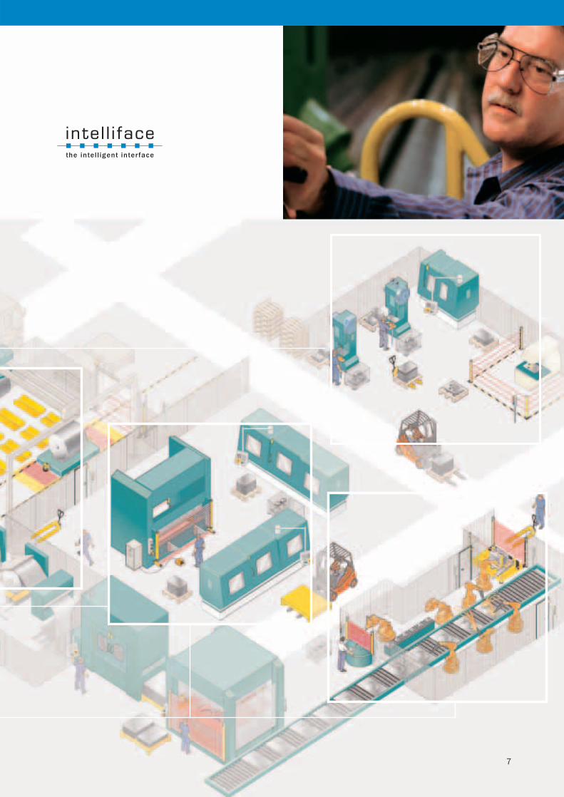
Intelliface connects.
From the simple machine to the complex manufacturing system:
Intelliface interface modules enable you to protect your hazardous areas.
SICK provides the connection, irrespective of the complexity of the network.
Safety relays
The series UE 10 to UE 48 safety relays enable
electromechanical and opto-electronic compo-
nents to be simply integrated into a machine or
system. From emergency stop to laser scanner —
12 product families are available.
Safety controllers
Series UE 100 — the device series
for complex applications with medium
network complexity. If you want to
connect your network more con-
veniently than with conventional relay
technology, the solution is UE 100.
Using the UE 100 series, two indepen-
dent or dependent complex safety
applications can be solved.
Safety network solutions
Series UE 1000 solutions are designed for
machines and systems with high network
complexity and programmable controls.
Series UE 1000 modules enable safety-relevant
components to be integrated and evaluated
in bus systems as well as solving complete
safety applications.
UE 100 series
UE 1000 series
UE 10 – 48 series
Competence Products Applications Complete programmeService
7

Press applications
(UE470)
Simultaneous protective
field evaluation
Integrated configuration
memory: Automatic
configuration download
on sensor replacement
Simple commissioning, short MTTR
due to replaceable terminals
5 operating modes
Overview of main features
Safety controllers
UE 440/UE 470
You are looking for the right
interface module for your
application?
SICK will provide the flexible
solution for different require-
ments.
With our product line, the
optimal product for almost
every application
is available to you — easy
to service, easy to use and
certified.
User modes
1
23
45
EN 954-1/
IEC 61508
Inputs
Safety outputs
Application
diagnostics output
Protection class
Configuration
possibility
Applications
Products
Up to cat. 4/–
1- or 2-channel
2 … 6 relays
1 … 4 relays
IP 20
–
Mechanical locking
(UE 44-3SL)
–
–
–
UE 10 to UE 48
Cat. 4/SIL 3
1 or 2-channel,
15 safety inputs — of which
3 are 2-channel safety inputs,
two ESPE interfaces (Cat. 4)
4 semiconductor outputs (OSSD)
4 semiconductor outputs
IP 20
Drag and Drop Software (CDS)
UE 440, UE 470
Safety sensor system that can be integrated
Interface modules
for all requirements
from a single
source.
Safety relays
UE 10 – UE 48 series
Simple machine Complex machine
Simple configuration via Drag and
Drop with uniform user software CDS
The big online product
catalogue
www.sick.de/produktfinder
Added value
in the system
Competence Products Applications Complete programmeService

Standard sensors and safety
sensors on a single network
Easy commisioning because of
simple wiring
Easy configuration with Software
ASIMON
–
Simple configuration with uniform user
software CDS local or via PROFIBUS
Diagnostics via PROFIBUS
Master class 2
Simultaneous protective field
evaluation via safety PLC
Automatic configuration
download and operating
mode switching using
PLC via PROFIBUS
Standard sensors and safety sensors
in a network
Safety bus modules
UE 4100 PROFIsafe
Safety bus modules
UE 4200 AS-i Safety at Work
Cat. 4/SIL 3
16 1-channel or 8 2-channel
and two communication interfaces
for ESPE
Via PROFIsafe
up to 16 (with current monitoring
e. g. Muting Lamp)
IP 67
Safety PLC
PROFIsafe:
UE 4120, UE 4150, UE 4155
Easy configuration using NEDSI applet,
local or via DeviceNetTM
. Additional local
port for access to complete DeviceNet/
DeviceNet SafetyTM
network
Safety controller and network master
in a single compact device
Logical and application specific
function blocks for the complete
safety automation
Safety Network Controller for local and
remote Safety Inputs and -Outputs
Cat. 4/SIL 3
16 1-channel or 8 2-channel
8 1-channel or 4 2-channel
4 (1 with current monitoring
e. g. Muting Lamp)
IP 20
Drag and Drop Software
DeviceNet SafetyTM:
UE 4470
Cat. 4/–
1- or 2-channel
1 or 2 2-channel relay
1 … 2 relays
IP 20(UE 4231, UE 4232)
IP 65(UE 3212), IP 67(UE 4215)
Drag and Drop Software
AS-Interface Safety at Work:
UE 3212, UE 4215,
UE 4231, UE 4232
Safety Network Controller
UE 4470 DeviceNet SafetyTM
Easy configuration using NEDSI applet
or EDS, local or via DeviceNetTM
.
Configuration of intelligent Safety sensors
supported by NEDSI applet and CDS
Simultaneously monitored protective
fields
Intelligent diagnosis via DeviceNetTM
and Standard HMI
Standard and Safety sensors and -
actuators on a single network
Cat. 4/SIL 3
6 2-channel (UE 4420, UE 4450)
+ 2 ESPE interfaces (UE 4450)
2 up to 6 2-channel (UE 4421)
2 2-channel bipolar (UE 4420, UE 4450)
up to 4 2-channel /2 Relay (UE 4421)
12 (UE 4420/4450) (2 with current
monitoring e. g. Muting Lamps)
IP 20 (UE 4421)
IP 67 (UE 4420, UE 4450)
Drag and Drop Software
DeviceNet SafetyTM:
UE 4420, UE 4450, UE 4421
Safety bus modules
UE 4400 DeviceNet SafetyTM
Systemdiagnosis via
Software ASIMON
Network system Network system Network system Network system

Series UE10 to UE48
safety relays.
Emergency
stop
Switch
Safety mat*
* 4-wire technology
Product example UE 48:
Safety relay; suitable for
five sensor types
Instead of using a special relay for emergency stop,
switches, safety mats, light curtains or laser
scanners, the UE 48 can evaluate each of these
safety components up to cat. 4.
Using the series UE 10 to UE 48 safety relays, individual electromechanical
and opto-electronic safety components can be easily integrated into a machine.
12 family groups from emergency stop to laser scanners are available.
Light curtain
Laser scanner
Specially developed for SICK light curtains
and laser scanners
High safety, availability and service life
Reduced service effort due to coded plug-in
terminals
Compact, space saving design
Can be used up to cat. 4 in accordance
with EN 954-1
10
System and user advantages
Competence Products Applications Complete programmeService

Main application Input circuit Features UE device
UE 10 to UE 48 — selection made easy
two-channel
two-channel
two-channel
two-channel
two-channel
Expansion module
1) Safety switches with mechanical locking
1)
UE 43-2 MF
UE 43-3 MF
UE 43-6 MF
UE 45-3 S1 2 3
1 output
up to 3 s off-delayed
UE 45-3 S1 2 30
1 output
up to 30 s off-delayed
UE 44-3 SL 2 3
1 output
up to 3 s on-delayed
UE 44-3 SL 2 30
1 output
up to 30 s on-delayed
UE 11-4 DX
off-delayed
0.5, 1, 2 or 3 s
UE 42-2 HD
UE 10-3 OS
UE 48-2 OS
UE 48-3 OS
UE 10-4 XT
2
1
3
1
6
4
3
0
3
0
3
0
3
0
2
1
4
2
4
2
3
0
2
1
3
1
2
1
single-channel
11
Stopping
cat. 0
Stopping
cat. 0
Stopping
cat. 1
Stopping
cat. 0
Stopping
cat. 0
Stopping
cat. 0
UE 23-2 MF

Configurable safety controllers
of the UE 100 series.
UE 100 is the device series for complex machines and systems. If you want to connect your
network more conveniently than with conventional relay technology, the solution is UE 100.
Two independent or dependent
safety applications
Simple Drag-and-Drop
programming
Space saving
Simple wiring,
rapid commissioning
Intelligent communication
interface for electro-sensitive
protective equipment
Stopping cat. 0/1
Autoconfiguration using
parameter memory
Direct diagnostics
CDS interface
12
Product options UE 440/UE 470
2 ESPE interfaces of cat. 4 for intelligent sensors
like e. g. C 4000/S 3000
15 1-channel inputs, of which three can be used
as 2-channel
2 pairs of safe semiconductor outputs (Cat. 4)
with separate EDM and reset
4 wear-free semiconductor outputs
Stopping cat. 0 and 1
Easy to service and maintain due to uniform
configuration and diagnostics for device and
connected intelligent sensors, e. g. S 3000
and C 4000
Simple user-friendly logic programming via
Drag and Drop
Reduced wiring effort due to logical linking of
the safety sensors (AND, OR, NAND …)
Simple replication of the application by
uploading and downloading data sets
Secure against tampering due to different
password levels
Function expansion for intelligent SICK sensors
(simultaneous protective field monitoring S 3000)
Autoconfiguration of intelligent SICK sensors
(C 4000)
Fast reaction time (≤ 10 ms): optimisation of the
safety distances between man and machine
System and user advantages
Competence Products Applications Complete programmeService

Realise two applications (dependent/independent)
with one UE 440 solution
The access to the press from
the rear is protected with an
M 2000 Host /Guest System,
the C 2000 Guest mounted
horizontally is used for point-
of-operation guarding.
Access and hazardous area
protection using safety controller
for presses UE 470
Universal application with UE 440
Special applications with UE 470
Application example: Press protection
The hazardous point on a press is protected using
a UE 470 safety controller with a C 4000 safety light
curtain.
All signals directly related to pressing action such as
TDC, BDC and SCC are evaluated. The press is shut
down depending on the safety sensors connected.
For the safety application, the indication of PSDI,
“Reset require”, reset, EDM and emergency stop is
configured in the UE 470.
Simultaneous hazardous area
monitoring with UE440
The hazardous areas on two robot cells are
secured using a UE 440 safety controller in
conjunction with a S 3000 safety laser scanner.
For this purpose two safety applications are
configured in the UE 440.
The S 3000 laser scanner monitors the two
hazardous areas with 2 simultaneous protective
fields. When there is an object in one of the
protective fields, the monitored semiconductor
output for the related safety application is shut
down. The side access doors to the robot cells
are monitored by safety door switches. The
emergency stop function and the reset function
are also realised using the UE 440.
Hydraulic and eccentric presses
with UE 470
Certified safety function blocks, e.g. single PSDI,
two PSDI, protective operation
Evaluation of signals related to pressing action:
Top dead centre (TDC), bottom dead centre
(BDC), stop control contact (SCC)
13

Series UE 1000 safety bus modules.
The series UE 1000 safety bus modules enable safety-relevant components to be interfaced
to the fieldbus systems PROFIBUS DeviceNetTM
and AS-Interface.
Products
PROFIsafe
•UE 4120; UE 4150; UE 4155
Remote bus module in IP 67
DeviceNet Safety
• UE 4421 – Remote bus module in IP20
• UE 4420; UE 4450 – Remote bus module in IP67 for
sensors with contacts and ESPE and safety actuators
• UE4470 – Safety Network Controller for evaluation
of local and remote safety related signals
AS-Interface Safety at Work
•UE 3212; UE 4215
De-central bus connection in IP 65/67
For sensors fitted with contacts and ESPE
• UE 4231; UE 4232
Safety monitors for the evaluation of the
safety-related signals
Applications
For the de-central interfacing of safety-relevant
components in networked systems
14
For safety tasks up to cat. 4 (EN 954) or SIL 3
(IEC 61508)
For safety automation without control cabinet
design to IP 67 or IP 65
Open device technology for connecting different
sensor systems
Optimised connection for SICK electro-sensitive
protective equipment
Seamless configuration and diagnostics for
sensors as well as bus modules
System and user advantages
(in preparation)
Competence Products Applications Complete programmeService

15
Easy communication in PROFIBUS Networks
Seamless solution by SICK with the example of AS-Interface
Seamless solution by SICK with the example of DeviceNetTM

Emergency
stop
Safety
switch
Light curtain
Laser scanner
etc.
Safety
sensor
Safety operating
device
Configurable PROFIsafe products
in the UE 4100 series.
PROFIsafe is an extension of the PROFIBUS DP protocol for safety technology.
In the case of PROFIsafe, the communication between the PROFIsafe slaves and
the PROFIsafe master is protected against transmission errors and changes.
UE 4100
UE 4100 PROFIsafe is not only a de-central I/O
fieldbus node of IP-67 design for the connection
of “classic” safety components to the PROFIsafe
fieldbus system, but also an intelligent de-central
communication interface to complex safety com-
ponents, e. g. C 4000 and S 3000.
16
For safety tasks up to category 4 (EN 954) or
SIL 3 (IEC 61508)
IP-67 design for safety automation without
control cabinet
Reduced wiring effort
Safety Data Link (SDL): Optimised connection
for safety devices such as C 4000 and S 3000
Uniform configuration and diagnostics for bus
nodes and sensors using CDS
Configuration and diagnostics on the components
via PROFIBUS
System and user advantages
Competence Products Applications Complete programmeService

Application example: Two independently protected robot cells with PROFIsafe
17
Series UE 4100 PROFIsafe Bus Nodes
Common features of the UE 4120 and
UE 4150/UE 4155
8 field signal connections to connect active and
passive safety components up to safety category 4
Convenient configuration and diagnostics using the
Windows software CDS (Configuration & Diagnostic
Software)
Offline configuration of the system without fail-safe
PLC is possible
Support for PROFIsafe V1.20 10/2002
Support for PROFIBUS DP V1: Cyclic communication
with DP-Master Class 1 (central control)
Acyclic communication with DP-Master class 2
(configuration and diagnostics tool)
Additional features of the UE 4150
2 SDL connections for S 3000 and C 4000
Configuration and diagnostics on the components
connected to the SDL connection
Additional features of the UE 4155
2 SDL connections for S 3000 and C 4000
Usage of the expanded functions in the safety sensors on
the SDL, e. g. operating mode selector switch for C 4000
or protective field switching for S 3000
Configuration and diagnostics on all components connected
to the SDL connection
Expansion of the functions with function packages
for cross-routing between bus nodes and C 4000 or
S 3000 (e. g. de-central protective field switching by
means of the direct connection of a selector switch
to the bus node and cross-routing to the S 3000)
Components that can be connected:
Electro-sensitive protective equipment
Emergency stop button
Electromechanical safety switches
Safety operating devices
Control switches with lamps
Operating mode selector switch
Muting sensors
Muting lamp
Example applications:
Bodyshell manufacture and final assembly in the
car industry
• Robot cells
• Storage and conveyor systems
among others

Series UE 4400 programmable and
configurable products for DeviceNet SafetyTM
DeviceNet SafetyTM
incorporates safety-rated functionality into the DeviceNet fieldbus
architecture. SICK’s DeviceNet SafetyTM
product portfolio includes safety programmable
devices as well as remote I/O bus nodes supporting complete safety automation of
machinery and manufacturing processes.
Emergency
stop
Safety
switch
Light curtain
Laser scanner
etc.
UE 4400
The UE 4400 DeviceNet SafetyTM
product portfolio
includes all of the components needed to implement
a safe automation system. The system supports both
standard and safety capable inputs and -outputs.
Additionally, the UE 4450 series remote I/O devices
support the communication with SICK intelligent
safety devices such as C 4000 series safety light
curtains and S 3000 series laser scanners
Safety
sensor
Safety operating
device
18
For complete safety applications up to category 4
(EN 954) and SIL 3 (IEC 61508)
IP 67 bus node version for distributed safety
automation without control cabinet
Reduced wiring compared to point-to-point
hard-wired safety systems
Safety Data Link (SDL): Optimised connection
of intelligent C 4000 safety light curtain and
S 3000 safety laser scanner.
Standardised software for programming,
configuring and diagnosing controllers,
bus nodes including connected sensors
and the network.
Device programming, configuration, and
diagnostics can be communicated via the
DeviceNet SafetyTM
network
System and user advantages
(in preparation)
Competence Products Applications Complete programmeService

UE 4420/4450 IP 67 Remote I/O Bus Node Product Family
Provision of safety capable inputs and safety capable
outputs with rugged IP 67 enclosure for field based moun-
ting without the need for control cabinets
Only one safety field bus address is required for up to
14 sensors or actuators
Easy upgrade of standard DeviceNetTM
to DeviceNet
SafetyTM
using the installed base of sensors or actuators
Easy Installation utilising standard connectors
(e. g. M12 and mini)
Easy connection of intelligent sensors, like e. g. C 4000
safety light curtains or S 3000 safety laser scanners
UE 4470 IP 20 Safety Network Controller Product family
Safety automation with full complement of third-party
certified — logical and application specific – function blocks
Decentralised evaluation and logical combination of
safety sensors and -actuators
Supports both local and remote connection to safety
sensors and -actuators
Easy Installation utilising spring clamp-style pluggable terminal
blocks
Remote Configuration of other DeviceNet SafetyTM
devices
through local port via DeviceNet SafetyTM
Network
(*)in preparation
Application example : Two independently protected robot cells with DeviceNet SafetyTM
19
Complete suite of products for safety automation
up to category 4 (EN 954) and SIL 3 (IEC 61508)
of machinery and manufacturing process
Supports the upgrade of standard DeviceNetTM
to
DeviceNet SafetyTM
Seamless and comfortable configuration and diagnosis
of both standard and safety-rated devices or the system
and the network using Windows-based software
Offline configuration of the system without the need
for a safety PLC
Decentralized evaluation of both standard and safety
sensors and actuators
Easy integration of intelligent sensors like e. g. C 4000
safety light curtain and S 3000 safety laser scanner
UE 4421 IP 20 Remote I/O Bus Node Product Family
Provision of safety capable Inputs and safety capable
outputs with IP 20 enclosure for DIN Rail, panel
mounting
Only one fieldbus address is required for up to
16 sensors or actuators
Easy upgrade of standard DeviceNetTM
to
DeviceNet SafetyTM
using the installed base
of sensors or actuators
Easy Installation utilising spring clamp-style pluggable
terminal blocks
Safety capable outputs available as solid state or
relay contacts
Modular System for DeviceNet SafetyTM (*)

Series UE 4200 safety bus modules
for AS-Interface Safety at Work.
AS-Interface products in the UE 4200 series facilitate the easy integration of protective
devices into an existing or new AS-Interface network. Existing AS-Interface applications can
therefore be extended with safety-relevant functions.
UE 4200
The modules for the UE 4200 AS-Interface Safety at
Work provide connection options for a wide range of
electro-sensitive protective equipment as well as for
electromechanical safety sensors. With the related
safety monitors, the safety-related signals are evaluated
in the AS-Interface network.
20
Standardised solution for AS-Interface and
AS-Interface Safety at Work
For safety tasks up to category 4 (EN 954)
Bus circuit in IP 65 or IP 67 for de-central safety
automation without control cabinets
Connection for different safety light curtains
and scanners to AS-Interface Safety at Work
via UE 4215
Connection for E-stop and electromechanical
safety switches to AS-Interface Safety at Work
via UE 3212
AS-Interface Safety-at-Work monitors with one
or two safe shutdown paths (UE 4231/UE 4232)
System and user advantages
Photo
: via
sto
re s
yste
ms, G
MB
H, S
tutt
gart
Competence Products Applications Complete programmeService

Safe bus node UE 4215:
Connection for electro-sensitive protective equipment
(ESPE) with self-monitoring semiconductor outputs
Connection for the supply of the sender for an
ESPE system
For field use IP 67
A few possible applications in conjunction with various
safety components:
Hazardous point protection, e.g. with C 4000 from SICK
Access protection with and without muting, e. g. with
MSL from SICK
Hazardous point protection and access protection,
e. g. with C 2000/M 2000 from SICK
Area protection, e. g. with PLS, S 3000 from SICK
Safe bus node UE3212:
Connection for 1 or 2-channel electromechanical sensors
For field use IP 65
Some examples of components that can be connected:
Emergency stop button
Safety switches
Position switches
Safety monitors UE 4231/UE 4232:
Evaluation of the safety-relevant signals in the AS-Interface
network. It is possible to use of several safety monitors in
an AS-Interface network.
Example applications for AS-Interface Safety at Work:
Packaging machines
Foodstuff machines
Conveyor systems for individual items and bulk goods
Machine tools
Extensive machines with several control elements and
safety sensors for machining wood and metal
Safe integration of safety sensors and electromechanical safety devices
with AS-Interface Safety at Work
21
or
UE 4215 UE 3212
or

One application — three solutions.
Intelliface interface products make it possible to realise
different system solutions within one and the same
application.
Protection of the hazardous
point on the turntable on a
robot cell using the C 4000
safety light curtain
Protection of the following robot cell
with a S 3000 safety laser scanner
Monitoring of the side access door to
the front robot cell by a safety switch.
This switch shuts down the dangerous
movement when the guard is opened.
A restart interlock is configured for both
safety applications.
Two independent indicators signal that
a reset is necessary after the shut down
of one of the systems.
The system is activated again by operating
the control switch connected.
Three emergency stop buttons are connected;
these buttons shut down both safety
applications.
Every emergency stop acts independently
on both parts of the system.
Application example: Production area with two
independently protected robot cells.
22
1
2
3
1
2
3
1
2
3
3
Competence Products Applications Complete programmeService

Solution 1: UE 10 – UE 48 series
Solution 2 : UE 100 series
Solution 3 : UE 1000 series
UE 48-2 0S :
With the UE 48-2 OS safety components for the robot cells can be connec-
ted individually.
The safety relay monitors the laser scanner, the light curtain, the emergen-
cy stop buttons and the safety switch on the guard with one device type.
Restart interlock and external device monitoring can also be provided with
the UE 48-2 OS.
UE 440 :
Both safety applications can be realised with the UE 440. The safety appli-
cations are prepared conveniently using Drag and Drop with the configurati-
on software CDS.
Each part of the system shuts down the dangerous movement of the related
robot depending on the state of its inputs (C 4000, S 3000, safety switch).
The emergency stop buttons fitted to the parts of
the system act on both parts of the system independently. After an emer-
gency stop, each part of the system must be reset before the related part
can be started again.
UE 4100 PROFIsafe
One UE 4155 was used for each part of the system. All safety-
relevant signals for each robot cell are acquired via the bus circuit. The bus
nodes UE 4155 are configured for the devices connected such as the
emergency stop buttons, laser scanner, light curtain, reset, etc. using the
SICK CDS user interface.
Both bus nodes are simply integrated as slaves in the PLC with one PROFI-
BUS address each. The monitoring and functional control of
the two parts of the system is then performed via the safety PLC.
UE 4200 AS-Interface Safety at Work
To solve the application described with AS-Interface Safety at Work the
Monitor UE 4232 with two shut down paths, one for the 1st part of the
system and one for the 2nd part of the system, is used.
To interface the C 4000 light curtain and the S 3000 laser scanner, Slaves
UE 4215 are used. The safety switch and the emergency stop buttons are
integrated in the AS-Interface network using a module UE 3212.
UE 4400 DeviceNet SafetyTM
At each part of the application, one UE 4450 bus node collects all relevant
safety and standard signals and transfers them after pre-evaluation via
DeviceNet SafetyTM
to a UE 4470 Safety Network controller. The UE 4470
solves the complete safety application, using logical and application specific
function blocks.
The resulting safety relevant output signals are transmitted via DeviceNet
SafetyTM
to the UE 4450, switching off safely the robot cells. The system
offers comfortable diagnosis information e. g. for evaluation in standard
controllers or display at HMI terminals.
(in preparation)
23

Main features UE 10 and UE 100.
1) The connected control switch and the following control as well as the wiring and laying of the wiring must comply with the control category2) As for protective device3) As for basic device4)4) 4 normally open/2 normally closed contacts off-delayed
For technical data on the individual products, see product catalogue “Safety Relays UE 10 – UE 48 Series” (8009607)
Main features series UE 10 - UE 48
Safe
ty c
ateg
ory
in c
ompl
ianc
e w
ith E
N95
4-1
Basi
c de
vice
Expa
nsio
n m
odul
e
Emer
genc
y st
op b
utto
n (E
N41
8)
Safe
ty s
witc
hes
(EN
1088
)
Two-
hand
con
trol
s (T
ype
IIIC/
EN57
4)
Safe
ty m
ats
(onl
y 4-
wire
tech
nolo
gy)
Opt
o-el
ectr
onic
pro
tect
ive
devi
ces
(Typ
e2,
3,4)
Enab
le c
urre
nt p
aths
Sign
allin
g cu
rren
t pat
hs
Enab
le c
urre
nt p
aths
on-
dela
yed
Enab
le c
urre
nt p
aths
off-
dela
yed
1-ch
anne
l ope
ratio
n
2-ch
anne
l ope
ratio
n
Cros
s ci
rcui
t det
ectio
n
Auto
mat
ic re
set
Man
ual r
eset
(mon
itore
d)
Conc
urre
nce
mon
itorin
g (0
.5s)
Sync
hron
ous
time
mon
itorin
g (0
.5s)
Hou
sing
wid
th (m
m)
UE 42-2 HD 4 x - - x x - - 2 1 - - - x - x - x - 22.5
4 1)
x - x x - - - 2 1 - - x - - x x - - 22.5
4 x - x x - - - 2 1 - - x x x x x - x 22.5
4 x - x x - - - 3 1 - - x x x x x - x 45
4 x - x x - - - 6 4 - - x x x x x - x 90
2)x - - - - - x 3 1 - - - x - - - - - 22.5
4 x - x x - x x 2 1 - - x x x x x - - 22.5
4 x - x x - x x 3 0 - - x x x x x - - 22.5
4 x - x x - - - 2 - 1 - x x x x x - x 22.5
4 x - x x - - - 2 - - 1 x x x x x - x 22.5
3)- x - - - - - 4 2 - - - - - - - - - 22.5
3)- x - - - - - - - - 4/2
4)- - - - - - - 22.5
UE 23-2 MF
UE 43-2 MF
UE 43-3 MF
UE 43-6 MF
UE 10-3 OS
UE 48-2 OS
UE 48-3 OS
UE 44-3 SL
UE 45-3 S1
UE 10-4 XT
UE 11-4 DX
General Applications Contacts Functions
Main features
UE 10 to UE 48.
24
Competence Products Applications Complete programmeService

Supply voltage
Voltage tolerance
Residual ripple
(within the supply voltage limits)
Maximum power consumption
Protection class
Response time
Input delay (adjustable)
Discrepancy time on the inputs (adjustable)
Enclosure rating
Dimensions (W x H x D)
Main features UE 440/UE 470
24 V DC
± 20 %1)
≤ 10 %
4.5 A
III (safety extra-low voltage)
< 10 ms
0…90 ms
0…30 s
IP 20
65 x 120 x 100 mm3
S 3000 (EFI)
Outputs
Max. 8 OSSD
Max.
number
Max. 2
Max.
number2 pairs 2 2 2 8 4
Test pulse
outputs
Reset
lamp
Bypass
lamp
Signal out-
put (HIGH-
active)
Signal out-
put (LOW-
active)
Number of communication interfaces (EFI) to SICK sensors
C 4000 (EFI)
2 2
Inputs
Main features UE 440/UE 470 UE 470
Signals related to pressing actions
Max. 15
Max.
number
Operating
modes
5 15 3 2 2 3 2 2 1 1 1 1 1
Single-
channel
input
Two-
channel
input
Emergency
stop single-
channel
Emergency
stop two-
channel
ESPE
(OSSD)Reset
External
device
monitoring
Teach-inkey-operatedswitch
Key-operatedpushbuttonfor bypass
Bottom
dead
centre
Top
dead
centre
Stop
control
contact
1) Reverse polarity protected via safety transformer in accordance with EN 60742
Main features
UE 100.
25

Enclosure rating (IEC 60529)
Safety category
Internal processing time
Field signal inputs
Input voltage1) HIGH
Input delay (configurable)
Field-signal outputs
When status is ‘switched-on’
Output voltage HIGH (without load)
Switching current
Minimum current for fault monitoring on
field-signal connections 7 and 82)
SDL connections
Power supply
Current
Internal resistance
OSSD inputs
Input voltage HIGH
PROFIBUS connection
Baud rate
Address range
Manufacturer’s code
UE 4120
UE 4150/UE 4155
Operating data
Supply voltage Uv at device3)
Power consumption through power-supply connection
IP 67
Cat. 4 (EN 954), SIL 3 (IEC 61508)
6 ms
Minimum
11 V
0 ms
Uv
0 mA
7 mA
13 V
9.6 kBit/s
3
070F hex
071A hex
19.2 V
Typical
24 V
20 mA
24 V
24 V
Maximum
28.8 V
90 ms
700 mA
40 mA
1.4 A
0.3 Ω
28.8 V
12 MBit/s
125
28.8 V
9 A
Main features series UE 41xx
1) In compliance with IEC61131-2, Type 2
2) Only when the connec-tion is configured as an output for a mutinglamp
3) The external voltagesupply must be capableof buffering brief mainsvoltage failures of 20 ms as specified inEN 60204-1
Main features
UE 4100 PROFIsafe.
Main features UE 1000.
Competence Products Applications Complete programmeService

Supply voltage Uv1)
Total power consumption
Safety data
Safety category (EN 954)
Response time
Safe inputs
Input circuit
Current loading2)
Short-circuit detection
Short-circuit protected
Switching level HIGH signal
Input current HIGH/LOW
External supply
External voltage supply3)
Current load per module
Interface for AS-Interface
AS-Interface profile
AS-Interface specification
Product standard/EMC
Enclosure rating in
compliance with EN 60529
Ambient temperature
DC 26.5 ... 31.6 V
60 mA
PNP
PNP/NPN
200 mA
> 10 V
> 5 mA/< 1.5 mA
DC 24 V via ribbon cable
1.2 A
Reverse polarisation protection
S-7.B.O
S-0.B.E
2.1
EN 50295
IP 65
Operation: –25 ... +70 °C
Operation: –25 ... +65 °C
x
x
-
3
6
x
-
x
-
x
x
-
-
-
-
x
x
-
x
x
x
-
x
x
x
-
4
22
x
x
-
x
x
x
x
x
x
x
x
-
x
x
x
-
IP 67 - x
x
-
Display LED yellow Input signals x x
LED green AS-i voltage indication x x
LED red Fault x x
Addressing Via IR interface x x
Housing material PBTP (Pocan) x x
Weight 85 g - x
100 g x -
Connection to AS-Interface Via contact pins4) x x
Safety sensors that can be
connected
Electromechanical safety
sensorsx -
Electro-sensitive protective
equipment (ESPE) with
self-monitoring semicon-
ductor outputs (OSSD)
- x
Main features UE 3212 4215
1) In compliance with AS-Interface specification2) For all inputs in total3) In accordance with PELV via AS-Interface ribbon cable4) On FK or FKE base or FK-A or FKE-A base
For accessories, see technical description “SENSICK AS-i components” (8009362)
Configuration interface
Supply voltage Uv1)
Power consumption
Switch on delay
Safety data
Safety category (EN 954)
Response time
AS-Interface data
AS-Interface profile
Voltage range
Power consumption
Safety switching outputs
Enable circuits
Max. contact load
Continuous current
Housing
Enclosure rating in compliance
with EN 60529
Weight
Operating temp.
RS 232
DC 24 V +/–15 %
150 mA
200 mA
< 10 s
4
< 40 ms
Monitor 7.F
18.5 ... 31.6 V
< 45 mA
Floating normally opened
contacts
1 output pair
2 output pairs
1 A DC13 at DC 24 V
3 A AC15 at DC 230 V
3 A per output circuit
Housing IP 20
350 g
450 g
–20 ... +60 °C
x
x
x
-
x
x
x
x
x
x
x
x
-
x
x
x
x
x
-
x
x
x
-
x
x
x
x
x
x
x
x
-
x
x
x
x
x
Fastening
Snap-in fastening
for mounting rail as
per EN 50022
x x
-
x
x
Main features UE 4231 4232
Main features
UE 4200 AS-Interface Safety at Work.
27

Main features UE 1000.
Main features UE 4470Safety Network Controller
Main features UE 4470Safety Network Controller
Protection class
Category
IP 20
Cat. 4 (EN 954)SIL 3 (IEC 61508)
Supply voltage UL1, UL2, US 20.4 … 26.4 V DC
Supply voltage DeviceNet 11 … 25 V DC
Operating Temperature –10 … +55 °C
Response time 15 ms
Safety Capable Inputs
ON voltage 11 V DC min.
OFF voltage 5 V DC max.
OFF current 1 mA max.
Input current 6 mA typ.
8 Dual channel
Test/Signal Outputs 4 (one with current monitor)
Output type Current sourcing
Rated output current 700 mA max.
Over current detection Yes
Current type Current sourcing (PNP)
Rated output current 500 mA max.
Over current detection Yes
Safety Capable Outputs (Solid State) 4 Dual channel
Function blocks per application 128 max.
Function block inputs 8 max. (function block dependent)
Function block outputs 8 max. (function block dependent)
Logical Function Blocks AND
OR
NOT
Exclusive OR (EXOR)
Exclusive NOR (EXNOR)
Reset/Restart
Application Specific Function Blocks E-Stop Monitoring
ON-Delay Timer
OFF-Delay Timer
Signal Routing
EDM (External Device Monitoring)
Selector Switch
Safety Gate Monitoring
OSSD Monitoring
Two Hand Control Monitoring
Logic Engine Specifications
DeviceNet Safety I/O Communication
Originator connections 16 max.
Target connections (Safety) 4 max.
Slave connections (Standard) 2 max.
16 bytes max.I/O per connection
Single-cast I/O support Yes
YesMulti-cast I/O support
DeviceNet Safety I/O Communication
Slave connections (Standard) 2 max. to same MACID
Standard DeviceNet I/O Communication
Input Bytes (max.)/Output Bytes (max.)
MaximumNo. Svcs.
Poll Connection I/O size 16/16 1
Bitstrobe I/O size 8/0 1
COS Connection I/O size 16/16 1
Cyclic Connection I/O size 16/16 1
Main features UE 4470
DeviceNet SafetyTM
.(in preparation)
Note: Output bytes refer to the output data that is transmitted from a master
to a slave. Input bytes refer to the input data that is transmitted from
a slave to a master.
Competence Products Applications Complete programmeService

Main features
UE 4420/UE 4450
DeviceNet SafetyTM
.
Main features
UE 4421.
(in preparation)
Main features UE 4420/UE 4450
Protection class
Category
IP 67
Internal response time 15 ms
Power supply (In/Out, 7/8"Connector) Minimum Typical Maximum
19.2V DC 24 V DC 28.8V DC
19.2V DC 24 V DC 28.8V DC
11 V DC 24 V DC 25 V DC
Cat. 4 (EN 954)SIL 3 (IEC 61508)
Main features UE 4421- UE 4421- UE 4421-22EE900 22EE490 22EE330
Protection class
Category
IP 20
Supply voltage UL 20.4 … 26.4 V DC
Supply voltage DeviceNet 11 … 25 V DC
Cat. 4 (EN 954)SIL 3 (IEC 61508)
Logic supply voltageUL
Switchable supply voltage US
Supply voltage DeviceNet
Safety Capable Inputs(6 Dual Channel, M12 Connector)
Input voltage HIGH 11 V 24 V 30 V
–30 V 0 V 5 V
0 ms 120 ms
0 ms 30 s
Input voltage LOW
Input delay time
Discrepancy time
Test/Signal Outputs(12, M12- Connector)
In activated state
Output voltage HIGH UL –0.25 V UL –0.1 V UL
5 mA 500 mA 700 mASwitching current
5 mA 12 mA 25 mACurrent threshold for failure monitoringat field signal connections 1 and 2
Switching voltage high-side ACTIVE US –1.5 V US
0 V 1.5 V
0 mA 2 A
Switching voltage low-side ACTIVE
Switching current
Safety capable Outputs (2 Dual Channel, M12 Connector)
SDL Connections (UE 4450)(2, M23 Connector)
Supply 1.3 A
11 V 24 V 30 V
–30 V 0 V 5 V
6 max.
OSSD Inputs
Input voltage HIGH
Input voltage LOW
DeviceNet Safety I/O Communication(In/Out, 5 Pin Mini sealed)
Target connections
YesSingle-cast I/O support
YesMulti-cast I/O support
YesPoll Connection I/O support
Standard DeviceNet I/O Communication
YesBitstrobe I/O support
YesCOS Connection I/O support
YesCyclic Connection I/O support
1 µ F
1 H
Load capacitive
Load Inductive (Switching sequence 1/sec)
Operating Temperature –10 … +55 °C
Response time (Internal to Bus Node) 15 ms
Safety Capable Inputs
ON voltage 11 V DC min.
OFF voltage 5 V DC max.
OFF current 1 mA max.
Input current 6 mA typ., 20 mA max.
6 DualChannel
4 DualChannel
2 DualChannel
Test/Signal Outputs 4
Output type Current sourcing
Rated output current 700 mA max.
Over current detection Yes
Current type Currentsourcing
Minimum load 1 mA at 5 V DC
Maximum AC load 2 A at240 V AC
Maximum DC Load 2 A at 30 V DC
Service life, mechanical cycles min. 5.000.000
Service life, electrical cycles min. 100.000
500 mAmax.Rated output current
Over current detection Yes
Safety Outputs (Solid State) – 4 DualChannel
–
Safety Outputs (Relay) 2 DualChannel
DeviceNet Safety I/O Communication
Target connections 4 max.
Single-cast I/O support Yes
Multi-cast I/O support Yes
Standard DeviceNet I/O Communication
Poll Connection I/O size 5 bytes/1 byte
4 bytes/1 byte
3bytes/1byte
29

SICK — value-added services
Reducing time-to-market
Increasing machine availability
Increasing system productivity
Securing technical lead
Minimising costs and financial
risks
Competence Products Applications Complete programmeService
30

31
Safety Consulting
Application consulting
Technical advice on site
Project support
Preparation of safety concepts
Access to a wide range of application and
sector know-how provides comprehensive
problem solutions and shortens planning
times.
Training & Education
Product training
Seminars
User training
Specialist training modules
Flexible seminar and training programmes
generate knowledge that can be utilised
directly and secure quality.
Assured success
with safety.
Industrial Safety
Management.
Product Service
Technical information line
Support during commissioning
Repair and exchange service
Broad support for your SICK sensor solution
ensures reliable and productive system
operation.
Safety Inspection
Initial commissioning inspection
Periodic inspections
Stoptime measurements
Service contracts
Safety inspections ensure maximum system
availability and very high quality system safety
as well as documented and traceable results.

Field bus level
SDL (Safety Data Link) SDL
SDL
Safety photo-
electric switches
Linking safety-relevant
signals with Intelliface
series interface modules
Safety light curtains and multi-beam
photoelectric safety switches
Uniform
configuration
and diagnostics
software
Photoelectric switches
Safety controllers
Safety laser
scanners
Safety laser
scanners
Safety
switches
Safety bus
modules
Safety light curtains and
multi-beam photoelectric
safety switches
Safety muting
systems
Safety switches
Safety relays
Safety
sensors
Emergency stop
SICK safety systems — the right decision
for today and tomorrow
Safety engineering on
machines and systems:
Safe design, risk assessment
and documentation
Safety photo-
electric switch
systems
2-hand module
Safety
Network
Controller
Competence Products Applications Complete programmeService
32

SICK Industrial
Safety Systems
SICK Industrial Safety Systems
www.sick.de/safetysystems
Safety switches, sensors
and operating devices
Safety light curtains
• UE 4120, UE 4150, UE 4155
• UE 3212, UE 4215, UE 4231,
UE 4232
• UE 4420, UE 4421, UE 4450,
UE 4470
• UE 440
• UE 470
• UE 10 to UE 48
• C 4000 Micro
• C 4000 Basic
• C 4000 Standard/Advanced
• C 4000 Entry/Exit
• C 4000 Palletizer in preparation
• C 2000
• LGT
Multiple light beam
safety devices
Safety photoelectric switches
Safety bus modules and
Safety network controller
UE 1000 series
Safety controllers
UE 100 series
Safety relays
UE 10 series
• Safexpert
Safety software
• M 4000 in preparation
• MSL
• MSL/MSM
• M 2000
• Safety position switches
• Safety switches
with separate actuator
• Safety locking devices
• Safety sensors
• Safety operating devices
• L 4000 system
• WSU/WEU 26/2
• WS/WE 12-2 with LE 20
• WS/WE 18-2 with LE 20
• WS/WE 24-2 with LE 20
• WS/WE 27-2 with LE 20
• VS/VE 18-2 with LE 20
Safety laser scanners and
Safety camera system
• S 3000
• PLS
• PLS short range
• RLS
• V 4000 Press Brake
eCatalog
Product finder
Applications
and much more
(in preparation)
33

SICK AG · Industrial Safety Systems · Waldkirch · Germany · www.sick.com
Industrial Safety Systems Auto IdentIndustrial Sensors Analyzers and Process Instrumentation
Comprehensive safeguarding of both
personnel and machinery! As specialists
in Sensor Technology, SICK develops and
manufactures pioneering products for
providing protection in hazardous zones,
dangerous locations and for safeguarding
access points. By providing services,
which encompass all aspects of machine
safety and security, SICK is setting new
standards in Safety Technology.
System control, maintaining setpoints,
optimising process control and
monitoring the flow of materials – the
instruments and services for Analysis
and Process Measurement, supplied
by SICK-MAIHAK, are setting the
standards for these applications in
terms of Technology and Quality.
Whether the tasks involve identification,
handling, classification or volume
measurement, innovative Auto Ident
systems and laser measuring systems
function extremely reliably, even under
rapid cycle times. They conform to the
latest Standards and can be simply
and speedily integrated in all industrial
environments and external applications.
80
10
73
7/1
1-0
4 .
MR
H/
FD
.Printe
d in G
erm
any (
11
-04
) .
Sub
ject
to c
hange
witho
ut
no
tice
.0
2 W
B int1
7
Our complete range of sensors pro-
vides answers to suit any application
in the field of automation. Even under
rugged ambient conditions objects
are reliably detected, counted and
positioned in respect of their form,
location and surface finish, as well
as their distances established with
pin-point accuracy.
S I C KSensor In te l l i gence .
Contact:
A u s t r a l i a
Phone +61 3 9497 4100
1800 33 48 02 – tollfree
E-Mail [email protected]
B e l g i u m / L u x e m b o u r g
Phone +32 (0)2 466 55 66
E-Mail [email protected]
B r a s i l
Phone +55 11 5091- 4900
E-Mail [email protected]
C e s k á R e p u b l i k a
Phone +420 2 57 91 18 50
E-Mail [email protected]
C h i n a
Phone +852-2763 6966
E-Mail [email protected]
D a n m a r k
Phone +45 45 82 64 00
E-Mail [email protected]
D e u t s c h l a n d
Phone +49 (0)2 11 53 01- 260
E-Mail [email protected]
E s p a ñ a
Phone +34 93 480 31 00
E-Mail [email protected]
F r a n c e
Phone +33 1 64 62 35 00
E-Mail [email protected]
G r e a t B r i t a i n
Phone +44 (0)1727 831121
E-Mail [email protected]
I t a l i a
Phone +39 02 27 40 93 19
E-Mail [email protected]
J a p a n
Phone +81 (0)3 3358 1341
E-Mail [email protected]
K o r e a
Phone +82-2 786 6321/4
E-Mail [email protected]
N e d e r l a n d s
Phone +31 (0)30 229 25 44
E-Mail [email protected]
N o r g e
Phone +47 67 81 50 00
E-Mail [email protected]
Ö s t e r r e i c h
Phone +43 (0)22 36 62 28 8- 0
E-Mail [email protected]
P o l s k a
Phone +48 22 837 40 50
E-Mail [email protected]
S c h w e i z
Phone +41 41 619 29 39
E-Mail [email protected]
S i n g a p o r e
Phone +65 6744 3732
E-Mail [email protected]
S u o m i
Phone +358 - 9 -25 15 800
E-Mail [email protected]
S v e r i g e
Phone +46 8 680 64 50
E-Mail [email protected]
T a i w a n
Phone +886 2 2365 - 6292
E-Mail [email protected]
T ü r k i y e
Phone +90 216 388 95 90 pbx
E-Mail [email protected]
U S A / C a n a d a / M é x i c o
Phone +1(952) 941- 6780
1800 -325 -7425 – tollfree
E-Mail [email protected]
More representatives and
agencies in all major industrial
nations at www.sick.com