industrial technology: engineering -...
TRANSCRIPT
1
Sydney Technical High School
Industrial Technology:
Engineering
Year 9
Module 1 & 2: Structures & Mechanisms
Course Notes
2
Introduction to Engineering What is Engineering? Engineering is the art of applying scientific and mathematical principles, experience, judgment, and common sense to make things that benefit people. Engineers design bridges and important medical equipment as well as processes for cleaning up toxic spills and systems for mass transit. In other words, engineering is the process of producing a technical product or system to meet a specific need. Engineers have many different types of jobs to choose from, including research, design, analysis, development, testing, and sales positions. If you are interested in discovering new knowledge, you might consider a career as a research engineer. If you are imaginative and creative, design engineering may be for you. The work of analytical engineers most closely resembles what you do in your mathematics and science classes. If you like laboratory courses and conducting experiments, look into becoming a development engineer. Sales engineering could be a good choice if you are persuasive and like working with people. Engineering work is also organised by traditional academic fields of study. The five largest of these are chemical, civil, electrical, industrial, and mechanical engineering. There are also more specialized engineering fields, including aerospace, ocean, nuclear, biomedical, and environmental engineering. Areas of engineering What projects do these engineers become involved in? Aeronautical ___________________________________________________________________ Civil ___________________________________________________________________ Mechanical ___________________________________________________________________ Electrical ___________________________________________________________________ Biomedical ___________________________________________________________________ Great Engineers Like all fields and occupations engineering has seen some great people over the years. Below is a list of famous engineers. Write a paragraph about each engineer outlining what development/s they are most famous for. 1. Isambard Kingdom Brunel 2. Robert Stevenson 3. Alec Issigonis 4. James Dyson 5. Archimedes 6. John Roebling 7. Henry Bessemer 8. Rudolf Diesel
3
Engineering Principles Structures Terminology Word Definition Tension This is when an object is subjected to a stretching action. Some materials
deal well with tension loads, but brittle materials tend to be poor under tension.
Compression This is when an object undergoes a form of squashing. Brittle materials tend to perform well under compression loads.
Torsion This is a mechanism where an object undergoes twisting. Bending When an object is supported and tends to sag in between the supports Shear Is a slicing mechanism much like cutting paper with scissors. Beam Beams are structures where they are supported at one or both ends. Like a
log over a creek. Column A thick vertical member loaded in compression Strut A thick compression member that may be at any angle. Tie A tension member, usually thin. Brace A member that may be loaded in tension or compression to stabilise a
structure. Truss A structure where small straight members are connected together to form
triangles which are stronger than quadrilaterals. Cantilever A type of beam that is supported at one end only. Like the front wheel on
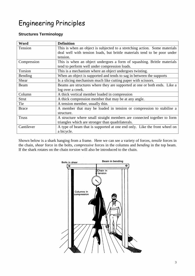
a bicycle. Shown below is a shark hanging from a frame. Here we can see a variety of forces, tensile forces in the chain, shear force in the bolts, compressive forces in the columns and bending in the top beam. If the shark rotates on the chain torsion will also be introduced to the chain.
Beam in bending

4
Types of Structures Bridges Bridges are designed to carry traffic of any type over an obstacle. Bridges are excellent examples of structures in action, especially because they have most of their structural members exposed to see. Bridges may be loosely grouped as beam, arch or suspension. Beam Bridges These consist of a horizontal beam supported at each end by piers. The weight of the beam pushes straight down on the piers. The farther apart its piers, the weaker the beam becomes. This is why beam bridges rarely span more than 100 metres. Another type of beam called the cantilever is only anchored on one end. In bridges cantilever bridges are often used with two or more cantilevers meeting in the middle.
Forth Bridge in Scotland – A steel truss cantilever bridge When a beam bridge bends under an applied load, the opposing sides will undergo different types of loads. The outside curve will be under tension, while the inner curve will be under compression. This means when we make a beam we must se a material that can withstand both tension and compression forces. Or alternatively we may use a composite material of two materials, one strong in compression and one strong in tension. Arch Bridges Arch bridges are one of the oldest types of bridges and have been around for thousands of years. Arch bridges have great natural strength. They were originally built of stone or brick but these days are built of reinforced concrete or steel. The introduction of these new materials allows arch bridges to be longer with lower spans. Instead of pushing straight down, the load of an arch bridge is carried outward along the curve of the arch to the supports at each end. The weight is transferred to the supports at either end.
5
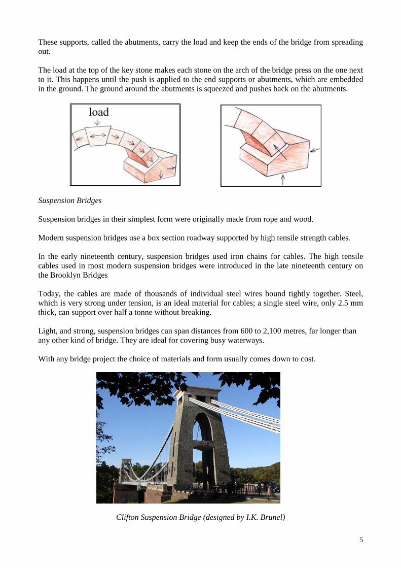
These supports, called the abutments, carry the load and keep the ends of the bridge from spreading out. The load at the top of the key stone makes each stone on the arch of the bridge press on the one next to it. This happens until the push is applied to the end supports or abutments, which are embedded in the ground. The ground around the abutments is squeezed and pushes back on the abutments. Suspension Bridges Suspension bridges in their simplest form were originally made from rope and wood. Modern suspension bridges use a box section roadway supported by high tensile strength cables. In the early nineteenth century, suspension bridges used iron chains for cables. The high tensile cables used in most modern suspension bridges were introduced in the late nineteenth century on the Brooklyn Bridges Today, the cables are made of thousands of individual steel wires bound tightly together. Steel, which is very strong under tension, is an ideal material for cables; a single steel wire, only 2.5 mm thick, can support over half a tonne without breaking. Light, and strong, suspension bridges can span distances from 600 to 2,100 metres, far longer than any other kind of bridge. They are ideal for covering busy waterways. With any bridge project the choice of materials and form usually comes down to cost.
Clifton Suspension Bridge (designed by I.K. Brunel)
6
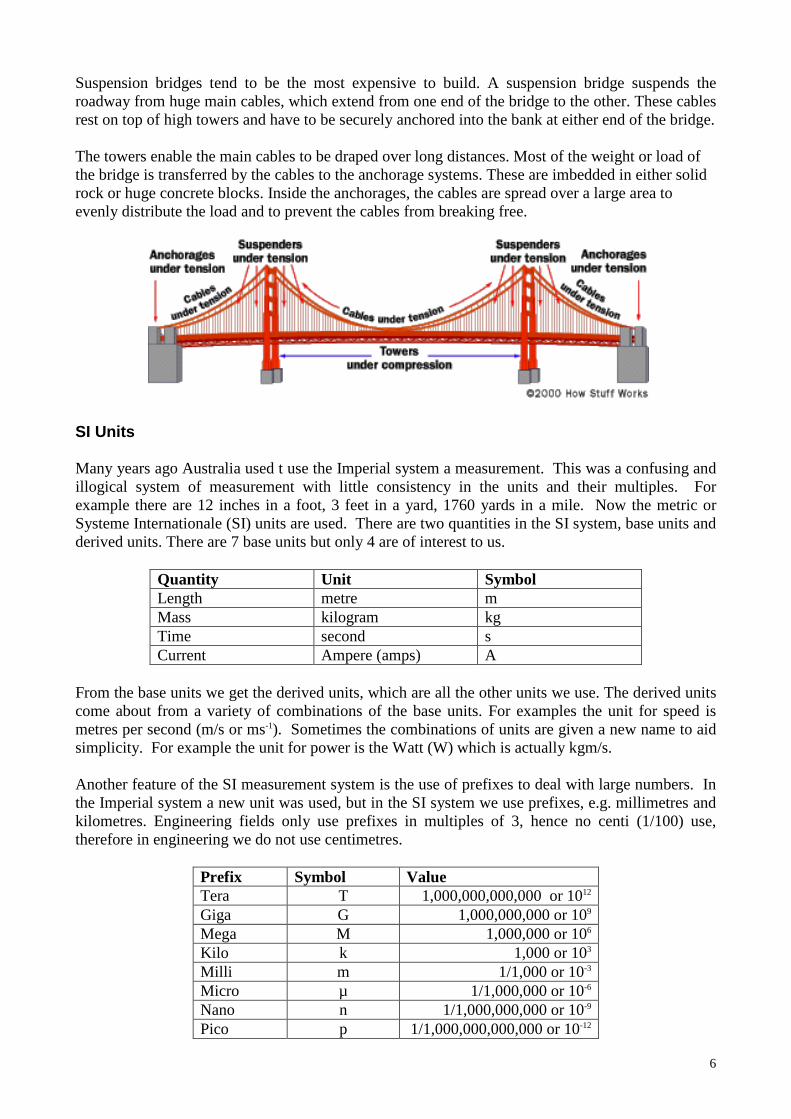
Suspension bridges tend to be the most expensive to build. A suspension bridge suspends the roadway from huge main cables, which extend from one end of the bridge to the other. These cables rest on top of high towers and have to be securely anchored into the bank at either end of the bridge. The towers enable the main cables to be draped over long distances. Most of the weight or load of the bridge is transferred by the cables to the anchorage systems. These are imbedded in either solid rock or huge concrete blocks. Inside the anchorages, the cables are spread over a large area to evenly distribute the load and to prevent the cables from breaking free. SI Units Many years ago Australia used t use the Imperial system a measurement. This was a confusing and illogical system of measurement with little consistency in the units and their multiples. For example there are 12 inches in a foot, 3 feet in a yard, 1760 yards in a mile. Now the metric or Systeme Internationale (SI) units are used. There are two quantities in the SI system, base units and derived units. There are 7 base units but only 4 are of interest to us.
Quantity Unit Symbol Length metre m Mass kilogram kg Time second s Current Ampere (amps) A
From the base units we get the derived units, which are all the other units we use. The derived units come about from a variety of combinations of the base units. For examples the unit for speed is metres per second (m/s or ms-1). Sometimes the combinations of units are given a new name to aid simplicity. For example the unit for power is the Watt (W) which is actually kgm/s. Another feature of the SI measurement system is the use of prefixes to deal with large numbers. In the Imperial system a new unit was used, but in the SI system we use prefixes, e.g. millimetres and kilometres. Engineering fields only use prefixes in multiples of 3, hence no centi (1/100) use, therefore in engineering we do not use centimetres.
Prefix Symbol Value Tera T 1,000,000,000,000 or 1012 Giga G 1,000,000,000 or 109 Mega M 1,000,000 or 106 Kilo k 1,000 or 103 Milli m 1/1,000 or 10-3 Micro µ 1/1,000,000 or 10-6 Nano n 1/1,000,000,000 or 10-9 Pico p 1/1,000,000,000,000 or 10-12
7
It should be noted that in terms of mass there is one unit that is not standard. We do not say 1000 kg is 1 Mg, instead we say 1000 kg equals 1 tonne (pronounced t-on). This is to accommodate a universally accepted Imperial unit called the ton (pronounced t-un). One tonne equals 0.984 ton. Review Questions 1. Convert the following quantities into more suitable values.
1,400 mm ___________________
23,450 N ___________________
0.00005 s ___________________
15,000 µA ___________________
45,600 kg ___________________
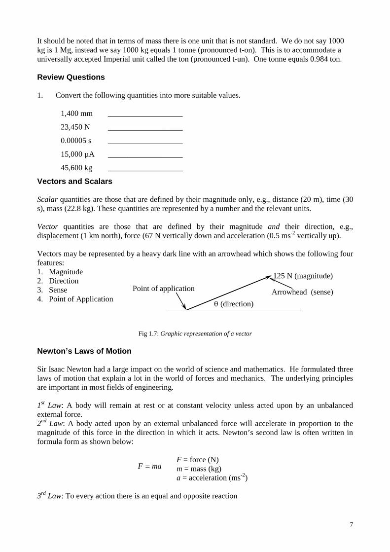
Vectors and Scalars Scalar quantities are those that are defined by their magnitude only, e.g., distance (20 m), time (30 s), mass (22.8 kg). These quantities are represented by a number and the relevant units. Vector quantities are those that are defined by their magnitude and their direction, e.g., displacement (1 km north), force (67 N vertically down and acceleration (0.5 ms-2 vertically up). Vectors may be represented by a heavy dark line with an arrowhead which shows the following four features: 1. Magnitude 2. Direction 3. Sense 4. Point of Application
Fig 1.7: Graphic representation of a vector
Newton’s Laws of Motion Sir Isaac Newton had a large impact on the world of science and mathematics. He formulated three laws of motion that explain a lot in the world of forces and mechanics. The underlying principles are important in most fields of engineering. 1st Law: A body will remain at rest or at constant velocity unless acted upon by an unbalanced external force. 2nd Law: A body acted upon by an external unbalanced force will accelerate in proportion to the magnitude of this force in the direction in which it acts. Newton’s second law is often written in formula form as shown below:
F = force (N) m = mass (kg) a = acceleration (ms-2)
3rd Law: To every action there is an equal and opposite reaction
125 N (magnitude)
θ (direction) Arrowhead (sense) Point of application
maF =
8
Mass, Force and Acceleration Mass: The amount of matter that a body contains with the SI unit being the kilogram (kg) Force: A force may be defined as a push or pull on a body. The SI unit for force is the Newton (N). Forces cannot be seen but their effects can be felt or seen. For example, when you go round a corner in a car, you do not see the forces but your body moves and you can feel the force acting on you. Acceleration: is the rate of change of velocity, or in other words how long it takes something to speed up or slow down. Because acceleration is a fundamental element in Newton’s second law it is pivotal in understanding the effect of gravity and how mass and force relate to each other. If a car moves from 0-100 km/h in 12 seconds and another car performs the same feat in 6 seconds the second car is accelerating twice as quickly. Since acceleration is a vector there can be negative acceleration: this is called deceleration. The SI unit for acceleration is metres per second squared (ms-2 or m/s2) Gravity: The Earth exerts a gravitational force on all bodies. The amount of the gravitational force depends on the mass of the objects and the distance between them. For all objects on the earth’s surface, the gravitational force accelerates at 9.8ms-2 towards the centre of the earth. In all calculations in this course acceleration due to gravity (g) is approximated to 10 ms-2; however some publications may use 9.8 ms-2. Weight: Do not confuse mass with weight. Weight is a force that is created by gravity acting upon a mass. When you “weigh” yourself on the scales at home your weight force acts on the scales causing the scales to give a reading. But because we are so used to using kilograms as a measure of our weight, the scales are calibrated in kilograms instead of Newtons. This convention is misleading as weight is a force and the units must be Newtons. If you are on the moon your mass will be the same as it was on earth but your weight will be less, as the moon has less gravitational force than the earth. In space you have no weight as there is no gravity but your mass is the same as it was on earth. Weight is the effect that the earth’s gravitational force has on a body. The weight of a body is the force created by the product of a body’s mass and the acceleration due to gravity. Thus the formula for weight is a variation of Newton’s second law. Therefore, W = weight (N) m = mass (kg) g = acceleration due to gravity (ms-2) This means that any mass will have a unit in kilograms, while a weight will have a unit in Newtons. If you want to know what your true weight is, multiply the reading you get off the scales (your mass) by 10. So if you have a mass of 60 kg, then your weight will be 600 N. Example 1 A car has a mass of 1100 kg, determine its weight.
W = ? m = 1100 kg g = 10 ms-2
mgW =
kN 11N 000,11101100
==
×==
WWW
mgW
9
Example 2 A car has a mass of 1.5 tonnes. Four people are sitting in the car and their average mass is 78 kg. Determine the total weight of the car and its occupants. Analysis: You need to convert the car’s mass in tonnes to kilograms then add all the masses together. You cannot add dissimilar units.
W = ? mC = mass of car = 1100 kg
mO = mass of each occupant = 78 kg g = 10 ms-2 Review Questions
1. Determine the weight of a 60 kg cable on a bridge. 2. A truck has a mass of 18 tonnes. If a 400 kg object is placed on the back of the truck what is
the total weight.
3. A bus has a mass of 8 tonnes. It carries 40 passengers with an average mass of 80 kg, determine the total weight of the bus.
4. A person weighs 750 N on Earth and is chosen to go to the Moon. If the acceleration due to
gravity on the moon is 1.6 ms-2, calculate the weight of the astronaut on the Moon.
5. A truck goes onto a weight bridge, the two rear axles register a weight of 15 kN and the front axle registers a weight on 10 kN, what is the total mass of the truck?
kN 12.18N 120,18
10))784(1500()4(
≈=
××+=+=
=
WWW
gmmWmgW
OC
10
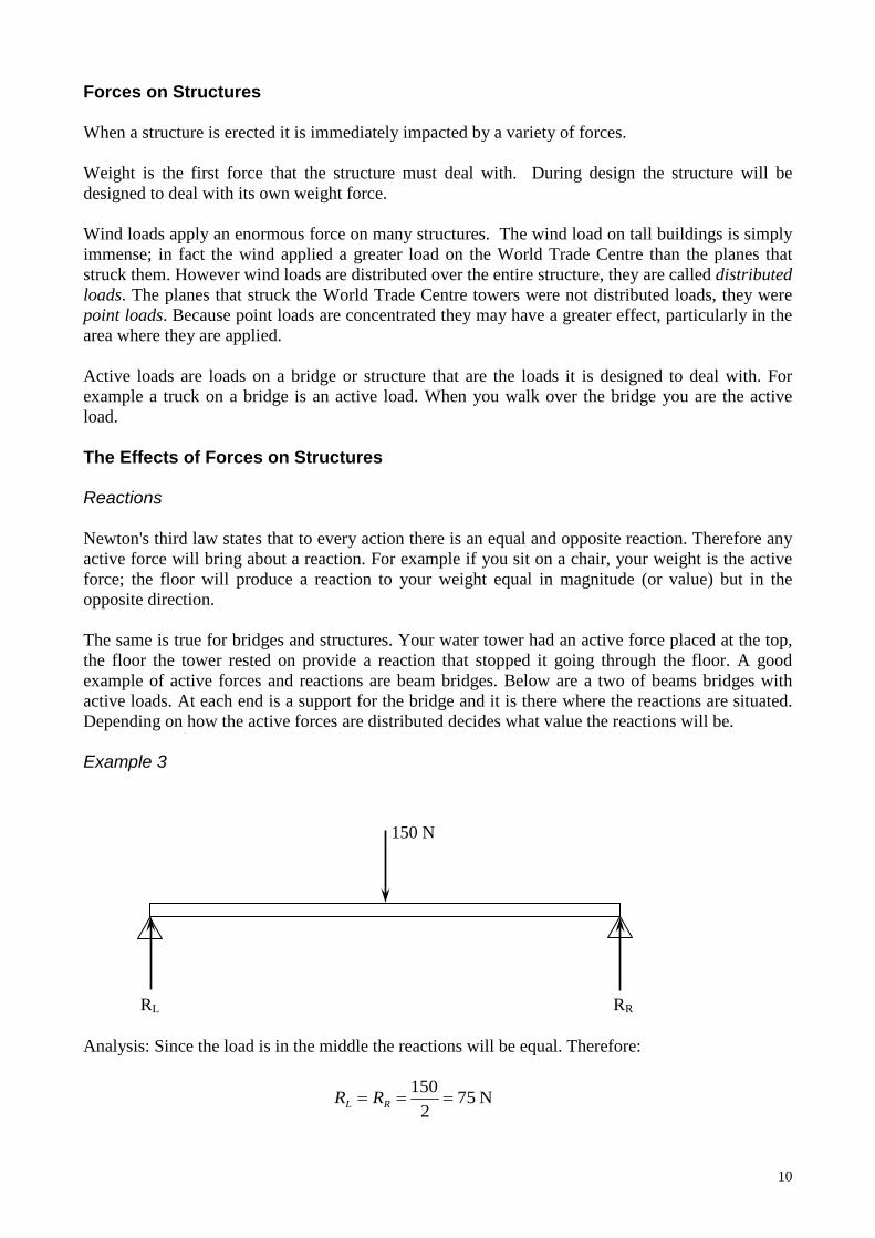
Forces on Structures When a structure is erected it is immediately impacted by a variety of forces. Weight is the first force that the structure must deal with. During design the structure will be designed to deal with its own weight force. Wind loads apply an enormous force on many structures. The wind load on tall buildings is simply immense; in fact the wind applied a greater load on the World Trade Centre than the planes that struck them. However wind loads are distributed over the entire structure, they are called distributed loads. The planes that struck the World Trade Centre towers were not distributed loads, they were point loads. Because point loads are concentrated they may have a greater effect, particularly in the area where they are applied. Active loads are loads on a bridge or structure that are the loads it is designed to deal with. For example a truck on a bridge is an active load. When you walk over the bridge you are the active load. The Effects of Forces on Structures Reactions Newton's third law states that to every action there is an equal and opposite reaction. Therefore any active force will bring about a reaction. For example if you sit on a chair, your weight is the active force; the floor will produce a reaction to your weight equal in magnitude (or value) but in the opposite direction. The same is true for bridges and structures. Your water tower had an active force placed at the top, the floor the tower rested on provide a reaction that stopped it going through the floor. A good example of active forces and reactions are beam bridges. Below are a two of beams bridges with active loads. At each end is a support for the bridge and it is there where the reactions are situated. Depending on how the active forces are distributed decides what value the reactions will be. Example 3 Analysis: Since the load is in the middle the reactions will be equal. Therefore:
N 752
150=== RL RR
150 N
RL RR
11
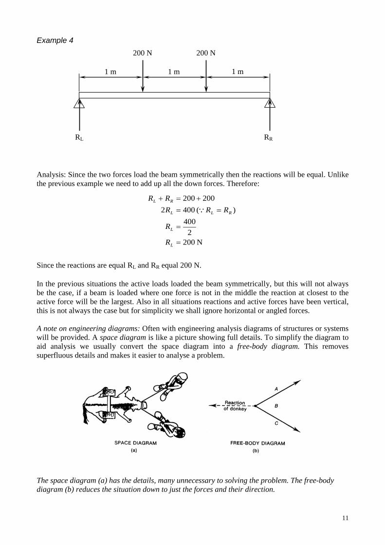
Example 4 Analysis: Since the two forces load the beam symmetrically then the reactions will be equal. Unlike the previous example we need to add up all the down forces. Therefore: Since the reactions are equal RL and RR equal 200 N. In the previous situations the active loads loaded the beam symmetrically, but this will not always be the case, if a beam is loaded where one force is not in the middle the reaction at closest to the active force will be the largest. Also in all situations reactions and active forces have been vertical, this is not always the case but for simplicity we shall ignore horizontal or angled forces. A note on engineering diagrams: Often with engineering analysis diagrams of structures or systems will be provided. A space diagram is like a picture showing full details. To simplify the diagram to aid analysis we usually convert the space diagram into a free-body diagram. This removes superfluous details and makes it easier to analyse a problem. The space diagram (a) has the details, many unnecessary to solving the problem. The free-body diagram (b) reduces the situation down to just the forces and their direction.
N 2002
400) ( 4002
200200
=
=
==+=+
L
L
RLL
RL
R
R
RRRRR
200 N
RL RR
200 N
1 m 1 m 1 m
12
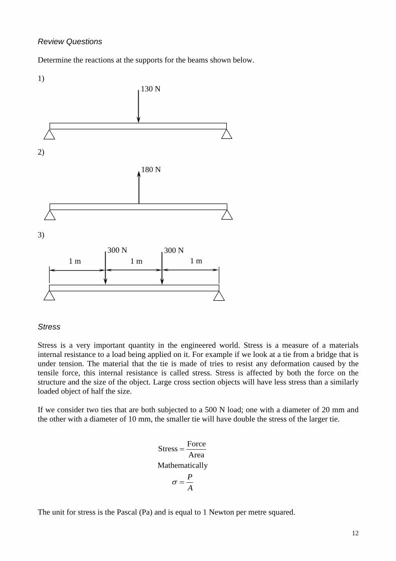
Review Questions Determine the reactions at the supports for the beams shown below. 1) 2) 3) Stress Stress is a very important quantity in the engineered world. Stress is a measure of a materials internal resistance to a load being applied on it. For example if we look at a tie from a bridge that is under tension. The material that the tie is made of tries to resist any deformation caused by the tensile force, this internal resistance is called stress. Stress is affected by both the force on the structure and the size of the object. Large cross section objects will have less stress than a similarly loaded object of half the size. If we consider two ties that are both subjected to a 500 N load; one with a diameter of 20 mm and the other with a diameter of 10 mm, the smaller tie will have double the stress of the larger tie. Mathematically The unit for stress is the Pascal (Pa) and is equal to 1 Newton per metre squared.
130 N
180 N
300 N 1 m 1 m
AP
=
=
σ
AreaForceStress
1 m 300 N
13
Example 5 A tie in a frame has a 900 N load on it, if the cross section is 10 mm square calculate the stress. Analysis: We need to convert all the values into base SI units, so 10 mm becomes 0.01 m. Therefore the cross sectional area is 0.0001 m2. So when that tie has a 900 N load on it the tensile stress within the tie is 9 MPa. Strain Strain is closely related to stress, but it measures deflection or deformation. Strain is a measure of the deformation compared to the original length. This is useful because a 10 mm deformation is more severe in an object if it is 100 mm long than if it were 1 metre long. The formula for strain is: Mathematically Since you are dividing two lengths the units cancel out, hence strain is a dimensionless quantity. Materials with high strain have undergone a large deformation relative to their original length. Ductile materials will allow high strain while brittle materials will not. Deflection When a load is applied to a structure there will usually be some type of deflection. Often the deflection may be tiny or indiscernible. Sydney Tower can withstand wind speeds of up to 172 km/h. At this speed it deflects up to I metre. Deflection at standard wind speeds is much less. Even though there is moderate deflection you are unlikely to feel it. The water towers we made also demonstrate deflection particularly in the compression members as they bend. Any type of beam will bend when loaded and this deflection may be large or very small depending on the load and the beam itself. Many structures are designed to a have an allowable deflection, the problem occurs when it exceeds that. Tacoma Narrows Bridge is an example of a structure where the deflection became too large.
MPa 9Pa 000,000,9
0001.0900
==
=
=
σσ
σ
σAP
Le
=
=
ε
Length OriginalnDeformatioStrain
14
FdM =
Nm 25.5675.075
=×=
=
MM
FdM
Moments of a Force Moments of a force are an exceedingly important concept in engineering mechanics. A moment is produced when a force causes or tends to cause rotation. Examples of moments are: • A force applied to a spanner which is over a nut causes the spanner to rotate, and thus loosen or
tighten the nut. • A force applied to a swing door as you walk through causes it to rotate on its hinges. • Winds acting on the side of a tall building cause a tendency for the building to sway. • When a bicycle rider pushes on the pedals the pedals rotate about their pivot. Each of these is an example of a moment caused by a force. Moments are expressed as clockwise or anti-clockwise and are vectors. In this course clockwise moments will be considered as positive. The value of a moment is found by multiplying the force’s magnitude by the perpendicular distance from the pivot point. The unit for the moment is Newton metres (Nm). Therefore the formula may be written as follows,
M = moment of the force (Nm) F = force (N) d = perpendicular distance of the force to the pivot (m)
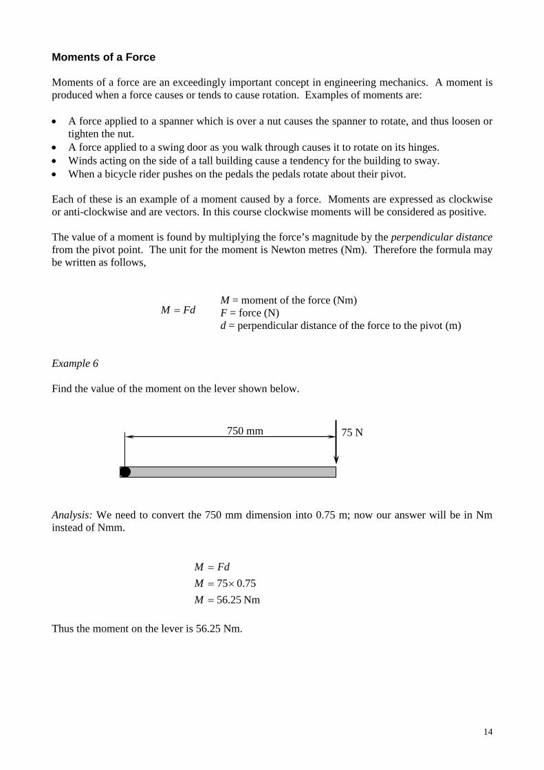
Example 6 Find the value of the moment on the lever shown below. Analysis: We need to convert the 750 mm dimension into 0.75 m; now our answer will be in Nm instead of Nmm. Thus the moment on the lever is 56.25 Nm.
75 N 750 mm
15
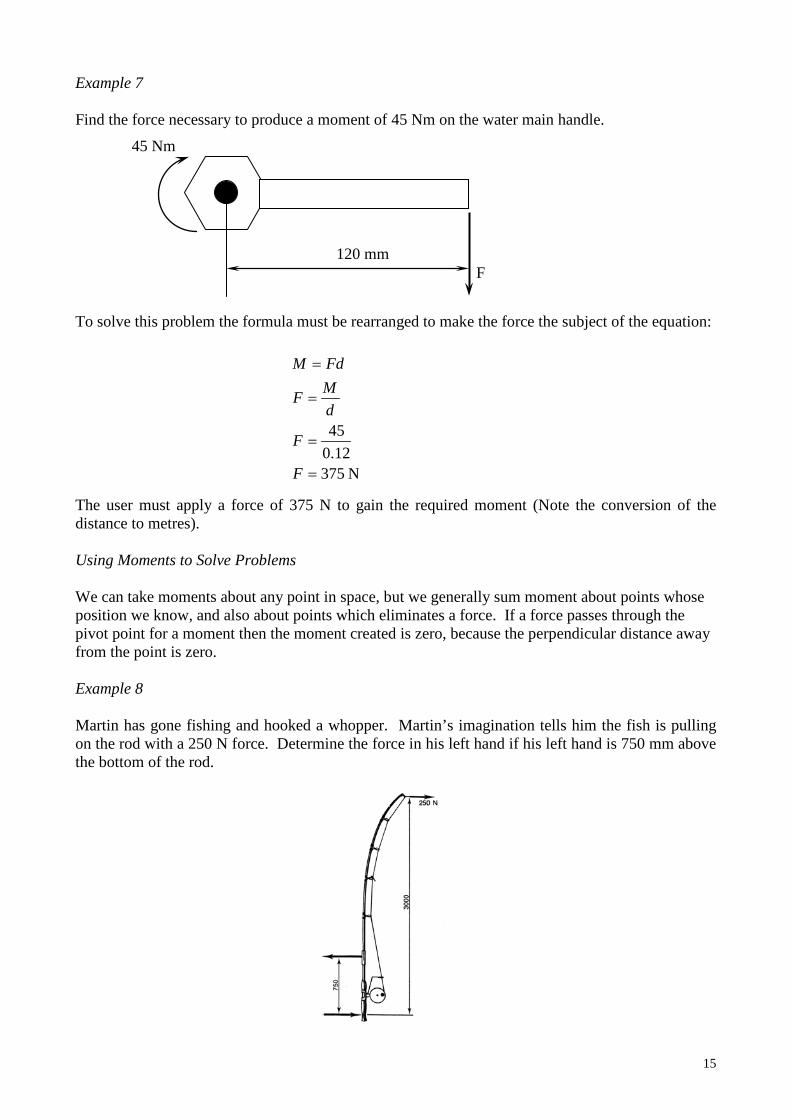
Example 7 Find the force necessary to produce a moment of 45 Nm on the water main handle. To solve this problem the formula must be rearranged to make the force the subject of the equation: The user must apply a force of 375 N to gain the required moment (Note the conversion of the distance to metres). Using Moments to Solve Problems We can take moments about any point in space, but we generally sum moment about points whose position we know, and also about points which eliminates a force. If a force passes through the pivot point for a moment then the moment created is zero, because the perpendicular distance away from the point is zero. Example 8 Martin has gone fishing and hooked a whopper. Martin’s imagination tells him the fish is pulling on the rod with a 250 N force. Determine the force in his left hand if his left hand is 750 mm above the bottom of the rod.
120 mm
45 Nm
N 37512.0
45
=
=
=
=
F
F
dMF
FdM
F
16
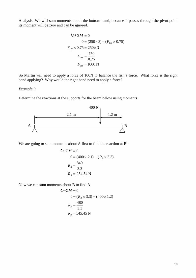
Analysis: We will sum moments about the bottom hand, because it passes through the pivot point its moment will be zero and can be ignored. So Martin will need to apply a force of 100N to balance the fish’s force. What force is the right hand applying? Why would the right hand need to apply a force? Example 9 Determine the reactions at the supports for the beam below using moments. We are going to sum moments about A first to find the reaction at B. Now we can sum moments about B to find A
400 N
2.1 m 1.2 m
A B
N 100075.0
750325075.0
)75.0()3250(00
=
=
×=××−×=
=Σ
LH
LH
LH
LH
F
F
FF
M+
N 54.2543.3
840)3.3()1.2400(0
0
=
=
×−×==Σ
B
B
B
R
R
RM+
N 45.1453.3
480)2.1400()3.3(0
0
=
=
×−×==Σ
A
A
A
R
R
RM+
17
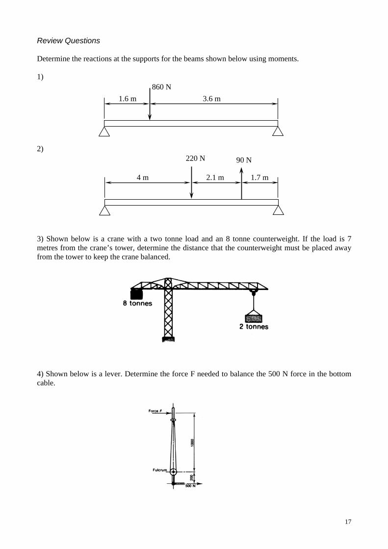
Review Questions Determine the reactions at the supports for the beams shown below using moments. 1) 2) 3) Shown below is a crane with a two tonne load and an 8 tonne counterweight. If the load is 7 metres from the crane’s tower, determine the distance that the counterweight must be placed away from the tower to keep the crane balanced. 4) Shown below is a lever. Determine the force F needed to balance the 500 N force in the bottom cable.
860 N
90 N 220 N
1.6 m 3.6 m
4 m 2.1 m 1.7 m
18
Mechanical Advantage and Velocity Ratio Mechanical Advantage (MA) The mechanical advantage of a machine is a measure of how it helps the user. Mechanical advantage in a mechanical machine is the ratio of load to effort and is found by the formula,
MA = mechanical advantage L = load E = effort
The higher the mechanical advantage, the lower the effort must be for a given load. If the mechanical advantage is below one, then we have a mechanical disadvantage, which means the effort is greater than the load. Mechanical advantage is not a constant value as friction and other losses in a system affect it, meaning the theoretical mechanical advantage may be considerably higher than the practical mechanical advantage. A large mechanical advantage would seem the best option but there are times when a low mechanical advantage is a better choice. A good example is the brake lever on a bike. If the lever is operated with your hand at the end then your fingers will move a greater distance but the effort will be lower. However if you apply the force to the brake lever near the pivot then the force required will be much greater but your fingers will move a much shorter distance. In some instances it is more desirable to sacrifice a low effort to allow smaller movements of the effort. Velocity Ratio (VR) The velocity ratio is the ratio of the distance the effort moves to the distance the load moves in a mechanical system. VR is represented by the formula,
VR = velocity ratio dE = distance the effort moves dL = distance the load moves
The higher the VR the greater the distance that the user must move. Unlike MA, VR is not affected by friction and system losses. If a machine is perfectly efficient (which is not practically possible) then MA will equal VR. However the lower the velocity ratio the greater the effort that is required. In the example on bike brake levers we can say that operating the lever at the end gives a high VR while operating it near the pivot gives a low VR. Thus in the first position your effort is less but your fingers travel further, while in the second position your fingers travel less but the required effort increases. Fishing rods have a low VR and a thus a low MA, which means the effort on the hand is greater than what the fish pulls at the end, but the end moves greater distances than the user’s hand, allowing a person to play the fish with small movements of the hand.
Investigation: Investigate the concept of mechanical advantage and velocity ratio by using some levers. Try a hammer extracting a nail, bike brake levers, a car gear stick and your forearm.
ELMA =
L
E
ddVR =
19
Efficiency (η) An ideal machine is one that is 100% efficient. That means all energy put into the machine is used. In reality, however, this never occurs. There is always some type of energy loss (usually as a result of friction) that results in the efficiency being below the ideal 100%. In the case of levers there may be friction in the pivots or the lever may bend slightly. VR is always the same irrespective of efficiency, since there no change in the distances the effort and load move. But MA is affected by a less than ideal efficiency; thus the MA will always be less than the VR for machines with efficiencies below 100%. The percentage efficiency is found by the following formula,
η = percentage efficiency MA = mechanical advantage VR = velocity ratio
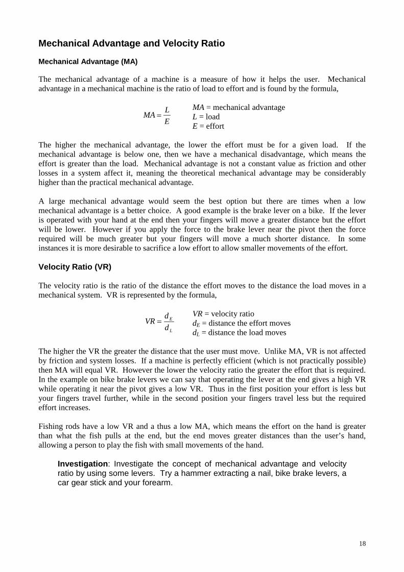
Orders of Levers Levers are one of the simplest machines used by engineers, yet they are the basis for many more complex machines. The use of retractors in surgery is an example of a simple lever, yet many machines are very complex devices filled with many levers. It must also be remembered that the human body is filled with levers, with most limbs operated by muscles and joints forming lever systems. The operation of levers can be divided into three forms or orders. First-order levers These levers have the load and the effort placed either side of the fulcrum (pivot). Examples include a crowbar used to lift, pliers, surgical retractors and a hammer pulling a nail out. The ratio of effort to load (called mechanical advantage) is dependent on their respective distances from the pivot.
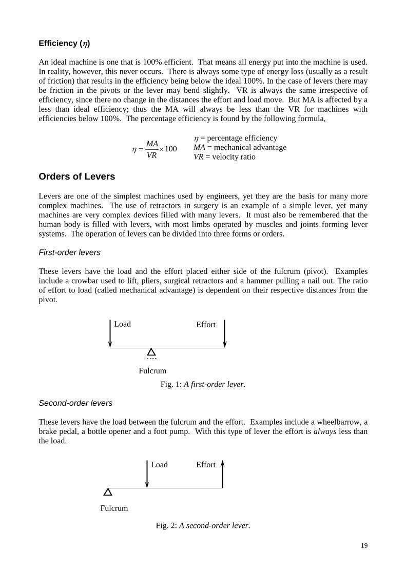
Fig. 1: A first-order lever. Second-order levers These levers have the load between the fulcrum and the effort. Examples include a wheelbarrow, a brake pedal, a bottle opener and a foot pump. With this type of lever the effort is always less than the load.
Fig. 2: A second-order lever.
100×=VRMAη
Load Effort
Fulcrum
Load Effort
Fulcrum
20
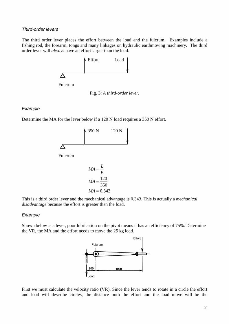
Third-order levers The third order lever places the effort between the load and the fulcrum. Examples include a fishing rod, the forearm, tongs and many linkages on hydraulic earthmoving machinery. The third order lever will always have an effort larger than the load.
Fig. 3: A third-order lever. Example Determine the MA for the lever below if a 120 N load requires a 350 N effort. This is a third order lever and the mechanical advantage is 0.343. This is actually a mechanical disadvantage because the effort is greater than the load. Example Shown below is a lever, poor lubrication on the pivot means it has an efficiency of 75%. Determine the VR, the MA and the effort needs to move the 25 kg load. First we must calculate the velocity ratio (VR). Since the lever tends to rotate in a circle the effort and load will describe circles, the distance both the effort and the load move will be the
Load Effort
Fulcrum
120 N 350 N
Fulcrum
343.0350120
=
=
=
MA
MA
ELMA
21
circumference of the circles. Since the circumference of a circle is found using 2πr (or πD) with the radius being the distance the load and effort are from the fulcrum.
Now we have the VR we can calculate the MA using the efficiency formula.
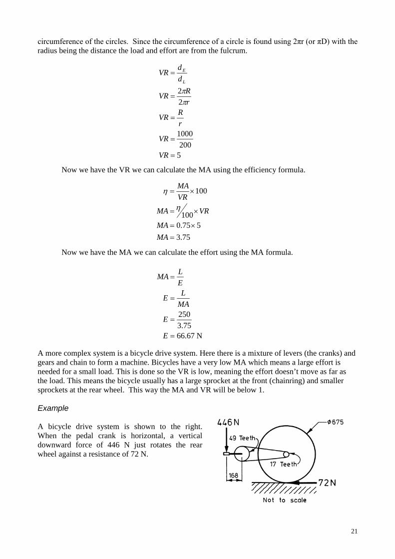
Now we have the MA we can calculate the effort using the MA formula. A more complex system is a bicycle drive system. Here there is a mixture of levers (the cranks) and gears and chain to form a machine. Bicycles have a very low MA which means a large effort is needed for a small load. This is done so the VR is low, meaning the effort doesn’t move as far as the load. This means the bicycle usually has a large sprocket at the front (chainring) and smaller sprockets at the rear wheel. This way the MA and VR will be below 1. Example A bicycle drive system is shown to the right. When the pedal crank is horizontal, a vertical downward force of 446 N just rotates the rear wheel against a resistance of 72 N.
5200
1000
22
=
=
=
=
=
VR
VR
rRVR
rRVR
ddVR
L
E
ππ
75.3575.0
100
100
=×=
×=
×=
MAMA
VRMA
VRMA
η
η
N 67.6675.3
250
=
=
=
=
E
E
MALE
ELMA
22
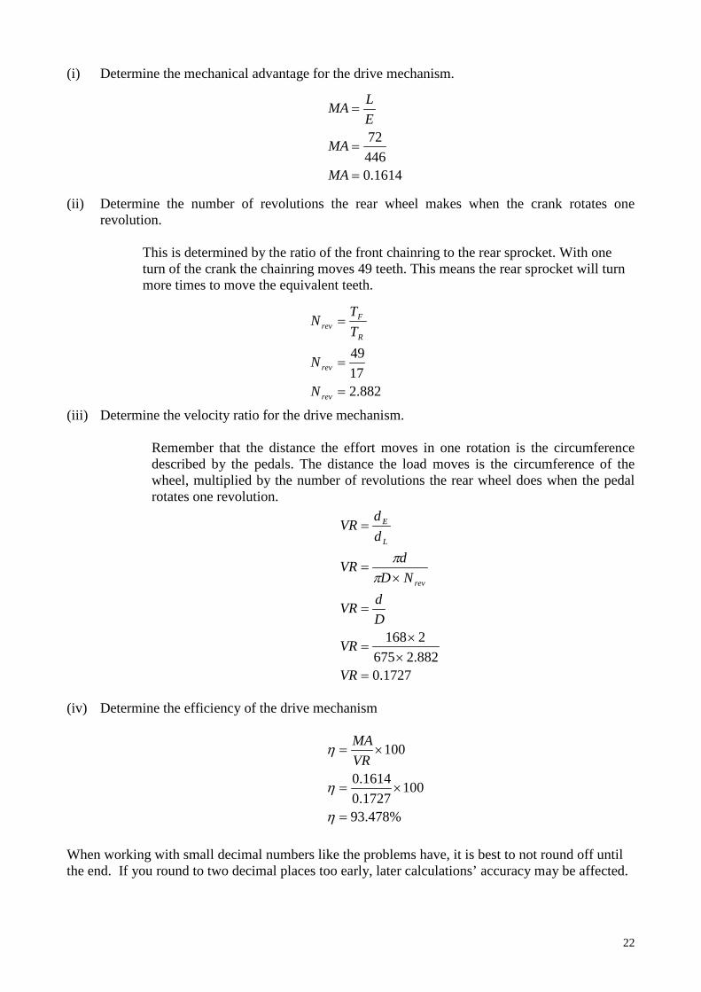
(i) Determine the mechanical advantage for the drive mechanism.
(ii) Determine the number of revolutions the rear wheel makes when the crank rotates one revolution.
This is determined by the ratio of the front chainring to the rear sprocket. With one turn of the crank the chainring moves 49 teeth. This means the rear sprocket will turn more times to move the equivalent teeth.
(iii) Determine the velocity ratio for the drive mechanism.
Remember that the distance the effort moves in one rotation is the circumference described by the pedals. The distance the load moves is the circumference of the wheel, multiplied by the number of revolutions the rear wheel does when the pedal rotates one revolution.
(iv) Determine the efficiency of the drive mechanism
When working with small decimal numbers like the problems have, it is best to not round off until the end. If you round to two decimal places too early, later calculations’ accuracy may be affected.
1614.044672
=
=
=
MA
MA
ELMA
882.21749
=
=
=
rev
rev
R
Frev
N
N
TTN
1727.0882.26752168
=××
=
=
×=
=
VR
VR
DdVR
NDdVR
ddVR
rev
L
E
ππ
%478.93
1001727.01614.0
100
=
×=
×=
η
η
ηVRMA

23