infantry - operation: east wind · · 2010-02-16task summaries ... 2-76 071-312-4029 correct...
TRANSCRIPT
STP 7-11BCHM1-SM
SOLDIER’S MANUAL
MOS 11B, 11C, 11H, 11M
INFANTRY
SKILL LEVEL 1
HEADQUARTERS DEPARTMENT OF THE ARMY
DISTRIBUTION RESTRICTION: Approved for public release; distribution is unlimited.

STP 7-11BCHM1-SM 1 MARCH 2000
0000507 DISTRIBUTION: Active Army, Army National Guard, and U. S. Army Reserve: To be distributed in accordance with the initial distribution number 115794, requirements for STP 7-11BCHM1-SM-TG.
By Order of the Secretary of the Army:
ERIC K. SHINSEKI General, United States Army
Chief of Staff Official:
JOEL B. HUDSON Administrative Assistant to the
Secretary of the Army

______________________________ DISTRIBUTION RESTRICTION: Approved for public release; distribution is unlimited. *This publication supersedes Chapter 1, pages 3-1 through 3-453, and all acronyms, abbreviations, and references that apply to 11BCHM skill level 1 tasks, of STP 7-11BCHM14-SM-TG, 30 September 1988.
i
*STP 7-11BCHM1-SM
Soldier Training Publication Headquarters NO. 7-11BCHM1-SM Department of the Army
Washington, DC, 1 March 2000
SOLDIER'S MANUAL
MOS 11B, 11C, 11H, AND 11M INFANTRY SKILL LEVEL 1
CONTENTS
Page PREFACE ........................................................................................................................ vii CHAPTER 1. INTRODUCTION 1-1. Task Summaries ........................................................................... 1-1 1-2. Soldier's Responsibilities .............................................................. 1-2 1-3. Training Support ........................................................................... 1-2 CHAPTER 2. MOS SKILL LEVEL TASKS
WEAPONS, GENERAL 071-317-0000 Prepare an Antiarmor Range Card ....................................................... 2-1
Page
M9 PISTOL 071-004-0001 Maintain an M9 Pistol ........................................................................ 2-11 071-004-0002 Perform a Function Check on an M9 Pistol ....................................... 2-19

STP 7-11BCHM1-SM
ii
071-004-0003 Load an M9 Pistol .............................................................................. 2-22 071-004-0006 Engage Targets with an M9 Pistol ...................................................... 2-24 071-004-0005 Correct Malfunctions of an M9 Pistol ................................................ 2-32 071-004-0004 Unload an M9 Pistol ........................................................................... 2-34
M16A1/A2 RIFLE 071-311-2006 Construct Field-Expedient Firing Aids for an M16A1 or M16A2 Rifle ....................................................................................... 2-36 071-315-2307 Zero a Night Vision Sight AN/PVS-4 to an M16A1 or M16A2 Rifle ....................................................................................... 2-39 071-315-2308 Engage Targets with an M16A1 or M16A2 Rifle Using a Night Vision Sight AN/PVS-4 ......................................................... 2-45
M249 MACHINE GUN 071-312-4025 Maintain an M249 Machine Gun ....................................................... 2-49 071-312-4026 Perform a Function Check on an M249 Machine Gun ....................... 2-70 071-312-4027 Load an M249 Machine Gun .............................................................. 2-72 071-312-4028 Unload an M249 Machine Gun .......................................................... 2-76 071-312-4029 Correct Malfunctions of an M249 Machine Gun ............................... 2-78 071-312-4004 Lay an M249 Machine Gun Using Field-Expedient Methods ........... 2-82 071-312-4030 Zero an M249 Machine Gun .............................................................. 2-85 071-010-0006 Engage Targets with an M249 Machine Gun ..................................... 2-90 071-010-0002 Mount a Night Vision Sight AN/PVS-4 on an M249 Machine Gun .................................................................. 2-99 071-010-0001 Zero a Night Vision Sight AN/PVS-4 to an M249 Machine Gun ................................................................. 2-102 071-010-0007 Engage Targets with an M249 Machine Gun Using a Night Vision Sight AN/PVS-4 ............................................ 2-105 071-010-0003 Dismount a Night Vision Sight AN/PVS-4 from an M249 Machine Gun ............................................................ 2-109
M60 MACHINE GUN 071-312-3004 Construct a Fighting Position for an M60 Machine Gun ................. 2-111 071-312-3030 Zero an M60 Machine Gun .............................................................. 2-117 071-315-2313 Zero a Night Vision Sight AN/PVS-4 to an M60 Machine Gun ..................................................................................... 2-120
Page 071-315-0008 Engage Targets with an M60 Machine Gun Using a Night Vision Sight AN/PVS-4 ......................................................... 2-125

STP 7-11BCHM1-SM
iii
CALIBER .50 M2 MACHINE GUN 071-022-0001 Maintain a Caliber .50 M2 Machine Gun.......................................... 2-129 071-022-0003 Load a Caliber .50 Machine Gun ...................................................... 2-156 071-313-3455 Set Headspace and Timing on a Caliber .50 M2 Machine Gun .............................................................................. 2-158 071-313-3454 Engage Targets with a Caliber .50 M2 Machine Gun ...................... 2-165 071-022-0005 Correct Malfunctions of a Caliber .50 Machine Gun ....................... 2-174 071-022-0004 Unload a Caliber .50 Machine Gun .................................................. 2-179
MK 19 MACHINE GUN 071-030-0001 Maintain a MK 19 Machine Gun ...................................................... 2-181 071-030-0011 Mount a MK 19 Machine Gun on an M3 Tripod ............................. 2-201 071-030-0009 Mount a MK 19 Machine Gun on a Vehicle .................................... 2-208 071-030-0007 Perform a Function Check on a MK 19 Machine Gun ..................... 2-218 071-030-0005 Load a MK 19 Machine Gun ............................................................ 2-221 071-030-0003 Zero a MK 19 Machine Gun ............................................................ 2-227 071-030-0004 Engage Targets with a MK 19 Machine Gun ................................... 2-230 071-030-0008 Correct Malfunctions of a MK 19 Machine Gun ............................. 2-238 071-030-0006 Unload a MK 19 Machine Gun ........................................................ 2-244 071-030-0012 Dismount a MK 19 Machine Gun from an M3 Tripod .................... 2-248 071-030-0010 Dismount a MK 19 Machine Gun from a Vehicle ........................... 2-250
M203 GRENADE LAUNCHER 071-311-2126 Perform a Function Check on an M203 Grenade Launcher.............. 2-252 071-311-2125 Maintain an M203 Grenade Launcher .............................................. 2-254 071-032-0006 Construct Field-Expedient Firing Aids for an M203 Grenade Launcher .................................................................. 2-261 071-311-2103 Zero an M203 Grenade Launcher ..................................................... 2-264 071-315-2351 Zero a Night Vision Sight AN/PVS-4 to an M203 Grenade Launcher .................................................................. 2-268 071-315-2352 Engage Targets with an M203 Grenade Launcher Using a Night Vision Sight AN/PVS-4 ............................................ 2-273
M47 MEDIUM ANTITANK WEAPON 071-052-0003 Construct a Fighting Position for an M47 Medium Antitank Weapon .............................................................................. 2-277 071-317-3302 Prepare an M47 Medium Antitank Weapon for Firing .................... 2-283
Page 071-052-0005 Operate a Night Vision Sight AN/TAS-5 ......................................... 2-290 071-052-0006 Engage Targets with an M47 Medium Antitank Weapon ................ 2-297

STP 7-11BCHM1-SM
iv
071-317-3306 Perform Misfire Procedures on an M47 Medium Antitank Weapon ............................................................... 2-303 071-052-0004 Restore an M47 Medium Antitank Weapon to Carrying Configuration ................................................................ 2-306
M136 LAUNCHER 071-054-0001 Prepare an M136 Launcher for Firing .............................................. 2-308 071-054-0004 Engage Targets with an M136 Launcher .......................................... 2-314 071-054-0003 Perform Misfire Procedures on an M136 Launcher ......................... 2-323 071-054-0002 Restore an M136 Launcher to Carrying Configuration .................... 2-326
MINES AND DEMOLITIONS 051-192-1021 Locate Mines by Visual Means ........................................................ 2-328 051-193-1025 Neutralize Mines .............................................................................. 2-330 071-098-0002 Install a Mechanical Ambush ........................................................... 2-333 071-098-0001 Recover a Mechanical Ambush ........................................................ 2-338
BASIC TACTICS 071-326-0501 Move as a Member of a Fire Team .................................................. 2-340 071-326-0512 Estimate Range ................................................................................. 2-344 071-410-0001 Perform Self-Extraction from a Minefield ....................................... 2-351
MOUT 071-326-0557 Select Hasty Firing Positions During MOUT .................................. 2-357 071-326-0550 Prepare Positions for Individual and Crew-Served Weapons During MOUT .................................................................................. 2-361 071-326-0541 Perform Movement Techniques During MOUT .............................. 2-372
SUSTAIN, GENERAL 081-831-1043 Practice Preventive Medicine ........................................................... 2-380
NBC 031-503-1021 Mark NBC Contaminated Area ........................................................ 2-386 031-503-1022 Decontaminate Equipment Using M13 Decontaminating Apparatus, Portable .......................................................................... 2-388
Page 031-503-2002 Decontaminate Equipment Using the ABC M11 Decontaminating Apparatus ............................................................. 2-391

STP 7-11BCHM1-SM
v
NIGHT VISION DEVICES 071-710-0009 Maintain Night Vision Goggles AN/PVS-7B .................................. 2-396 071-710-0008 Operate Night Vision Goggles AN/PVS-7B .................................... 2-404 071-315-0003 Operate Night Vision Sight AN/PVS-4 ............................................ 2-415 071-315-0030 Operate Night Vision Goggles AN/PVS-5 ....................................... 2-420 071-315-0091 Operate a Thermal Viewer AN/PAS-7 ............................................. 2-429
OPSEC AND COMSEC 071-730-0012 Identify Combat Vehicles ................................................................. 2-435 071-730-0013 Identify Weapons............................................................................... 2-441 071-730-0008 Employ Field-Expedient Early Warning Devices ............................ 2-462
RADIO 113-587-1064 Prepare SINCGARS (Manpack) for Operation ................................ 2-465 113-587-2070 Operate Secure SINCGARS Single Channel (SC) ........................... 2-468 113-587-2071 Operate Secure SINCGARS Frequency Hopping (FH) (Net Members) .................................................................................. 2-471 113-573-4006 Use the KTC 1400(*) Numerical Cipher/Authentication System..... 2-476 113-573-4003 Encode and Decode Messages Using KTC 600(*) Tactical Operations Code ............................................................................... 2-479
COMMUNICATIONS 113-600-2007 Operate Telephone Set TA-312/PT .................................................. 2-482 113-588-1087 Install Hot Loop ................................................................................ 2-483 APPENDIX A. PROPONENT SCHOOL OR AGENCY CODES .......................... A-1 APPENDIX B. EXAMPLE COMPLETED DA FORM 5164-R (HANDS-ON EVALUATION) ....................................................... B-1 APPENDIX C. CRITICAL TASKS ......................................................................... C-1 GLOSSARY ...................................................................................................... Glossary-1 REFERENCES .............................................................................................. References-1

STP 7-11BCHM1-SM
vi
PREFACE
This publication is for Skill Level 1 soldiers holding the military occupational specialties 11B, 11C, 11H, and 11M. It contains standardized training objectives, in the form of task summaries, to train on critical tasks that support unit missions during wartime. Soldiers holding MOS 11BCHM1 should have access to this publication. It should be made available in the work area, unit learning center, and unit libraries. This manual applies to both Active and Reserve Component soldiers. The proponent of this publication is the United States Army Infantry School. Send comments and recommendations on DA Form 2028 (Recommended Changes to Publications and Blank Forms) directly to-- Commandant, USAIS ATTN: ATSH-OTT-F/Building 4 Fort Benning, GA 31905-5593 [email protected] Unless this publication states otherwise, masculine nouns and pronouns do not refer exclusively to men.

1-1
CHAPTER 1
INTRODUCTION
This soldier's manual (SM) identifies the individual military occupational specialty training requirements for soldiers in MOS 11BCHM. Commanders, trainers, and soldiers should use it to plan, conduct, and evaluate individual training in units. This manual is the primary MOS reference to support the self-development and training of every soldier. It is used with the following manuals to establish effective training plans and programs that integrate soldier, leader, and collective tasks: • STP 7-11BCHM24-SM-TG. • The soldier's manuals of common tasks (STP 21-1-SMCT and
STP 21-24-SMCT). • Army Training and Evaluation Programs (ARTEPs). • FM 25-101.
1-1. TASK SUMMARIES Task summaries outline the wartime performance requirements of each critical task in the SM. They provide the soldier and the trainer with the information needed to prepare, conduct, and evaluate critical task training. As a minimum, task summaries include information the soldier must know and the skills that he must perform to standards for each task. The format for the task summaries included in this SM is as follows: a. Task Number. A 10-digit number identifies each task or skill. This task number, along with the task title, must be included in any correspondence pertaining to the task. b. Task Title. The task title identifies the action to be performed. c. Conditions. The task conditions identify all the equipment, tools, references, job aids, and supporting personnel that the soldier needs to use to perform the task in wartime. This section identifies any environmental conditions that can alter task performance, such as visibility, temperature, or wind. This section also identifies any specific cues or events that trigger task performance such as a chemical attack or identification of a threat vehicle. d. Standards. The task standards describe how well and to what level the task must be performed under wartime conditions. Standards are typically described in terms of accuracy, completeness, and speed. e. Training and Evaluation. The training evaluation section identifies specific actions (known as performance measures) that the soldier must do to successfully complete the task. These actions are in the evaluation guide section of the task summary and are listed in a pass/fail format for easy evaluation. For some tasks, the training and evaluation section may also include detailed training information in a training information outline and an evaluation preparation section. The evaluation preparation section indicates necessary modifications to task performance in order to train and evaluate a task that cannot be trained to the wartime conditions. It may also include special training and evaluation preparation instructions to accommodate these modifications, and any instructions that should be given to the soldier before evaluation.

STP 7-11BCHM1-SM
1-2
f. References. This section identifies references that provide more detailed and thorough explanations of task performance requirements than those given in the task summary description. g. Warnings. Warnings alert users to the possibility of immediate personal injury or damage to equipment. h. Notes. Notes provide a supportive explanation or hint that relates to the performance standards. 1-2. SOLDIER'S RESPONSIBILITIES Each soldier is responsible for performing individual tasks that the first-line supervisor identifies based on the unit's mission-essential task list (METL). The soldier must perform each task to the standards listed in the SM. If a soldier has a question about how to do a task or which tasks he must perform, he must ask the first-line supervisor for clarification. The first-line supervisor either knows how to perform each task or can direct the soldier to the appropriate training materials. 1-3. TRAINING SUPPORT This manual includes the following appendixes and information: a. Appendix A, Proponent School or Agency Codes. This appendix lists the proponent school or agency codes, which are the first three digits of the task number. b. Appendix B, Example Completed DA Form 5164-R (Hands-On Evaluation). This appendix shows an example completed DA Form 5164-R. This form is optional--trainers can reproduce it locally on 8 1/2 by 11-inch paper. They can find the original, reproducible form in the back of STP 21-24-SMCT, which also contains instructions for using the form. c. Glossary. The glossary, which follows the last appendix, is a single comprehensive list of acronyms, abbreviations, definitions, and letter symbols. d. References. This section contains two lists of references that support training of all tasks in this SM. “Needed” references are listed in the conditions statement and are required for the soldier to do the task. “Recommended” references are materials that help a trainer prepare for the task but are not required to perform the task.
2-1
CHAPTER 2
SKILL LEVEL 1 TASKS
WEAPONS, GENERAL
PREPARE AN ANTIARMOR RANGE CARD 071-317-0000
CONDITIONS Given a DA Form 5517-R and all pertinent data (as received from the squad leader’s briefing). STANDARDS Complete the standard range card form within 15 minutes. Include a scaled-down sketch of the terrain, marginal data, all data from the squad leader’s briefing, and the data section of the range card, which should include the unit designation (no higher than company level); a magnetic north arrow (properly oriented); a sector of fire, drawn in solid lines, which should clearly show the locations of left and right limits, maximum engagement line, dead spaces within the sector of fire; a target reference point(s); the weapon’s location, indicated by its distance and azimuth from and location relative to a known point (weapon reference point); and a data section, which should include type of position, date (day and month), weapon type, circle intervals (in meters), azimuth distance, and descriptive remarks about anything of particular interest or not covered previously.
TRAINING AND EVALUATION Training Information Outline
1. Definitions. a. Range card. A range card is a sketch of the terrain that a particular weapon has been assigned to cover by fire. The range card contains data that— (1) Helps leaders plan and control fires. (2) Orients replacement personnel or units. (3) Helps the gunner quickly and correctly detect and engage targets in his assigned sector of fire. b. Sector of fire. A sector of fire is the portion of battlefield each gunner must cover. Leaders show each gunner where to position his weapon and what part of the terrain he will be responsible for. Leaders use terrain features (target reference points) or azimuths to indicate the boundaries (left and right limits) of each sector of fire. They may assign each gunner a primary and a secondary sector of fire. c. Target reference points. The company commander chooses natural or man-made terrain features as TRPs. These help leaders and gunners locate targets and adjust fires.

STP 7-11BCHM1-SM
2-2
Each TRP is identified by a unique combination of letters, numbers, or both. Leaders show each gunner the TRP(s) in or near his sector of fire, and the gunner marks each TRP on his range card. Normally, each sector of fire has between one and three TRPs. d. Dead space. Dead space is any natural or man-made feature that the gunner cannot fire into or behind. For example, dead space could include a hill, draw, or building. Each gunner marks the dead spaces in his sector with diagonal lines (/////) or with the words, “DEAD SPACE.” Other weapons will cover dead spaces. e. Maximum engagement line. The area a gunner can cover is also limited by the weapon’s maximum engagement range. In some places, dead spaces may prevent the gunner from firing all the way to the maximum engagement range. Thus, he should draw the maximum engagement line in front of the dead spaces in his sector of fire. He can write out “MAXIMUM ENGAGEMENT LINE,” or he can shorten it to, “MAX ENG LINE.” f. Alternate and supplementary positions. Leaders may assign each gunner an alternate and supplementary position. Once leaders have given gunners the necessary information, each gunner may begin preparing a range card(s). He should prepare a separate range card for each assigned position (sector of fire).
EXAMPLE: Figure 1 shows the terrain used in this example. The sectionleader says to the squad leader, “I want you to cover a sector of fire that startshere at your firing position and goes to a point about ___ meters past thatwindmill on the left, moves to the right across the high ground at ___ metersbehind the houses, through the woodline, and behind the hill, church, andorchard, until it reaches a point about ___ meters beyond the right leadingedge of that orchard, then returns here to your firing position.
“The enemy will approach from the north, so they will use those two roads toenter our sector. On the road behind the church and the orchard, engageenemy armored vehicles as soon as they come into range. On the other road,engage enemy targets as soon as they appear from behind the left side of thatlarge hill. Copy down the two target reference points in your sector: Thewindmill is TRP C-1, and the church is TRP C-2.”

STP 7-11BCHM1-SM
2-3
CHURCH
WINDMILL
CHURCH
WINDMILL
Figure 1. Area of coverage.
2. Preparation of the range card. The leader gives the gunner the necessary information, and the gunner prepares the range card. If assigned a supplementary firing position, the gunner must prepare a range card for that also. To prepare the range card(s), he first must determine the following and write or draw it on the range card: a. Sector sketch. Draw a sector sketch that covers the entire sector. Draw the sketch as large as possible, but no larger than the outer circle. For large areas covered by trees or woods, draw only the outline and label the area “woods,” “orchard,” or whatever best describes it (Figure 2). In the lower part of the range card, indicate the firing position by placing a dot in the smallest arc. b. Left and right limits. Draw lines from the firing position to reflect left and right limits (Figure 3). Number the left limit “1” and the right limit “2.”
Figure 2. Sector sketch.

STP 7-11BCHM1-SM
2-4
Figure 3. Left and right limits.
c. Maximum engagement line. If no limitations exist, ensure the maximum engagement line follows the arc of the circle representing the maximum engagement range (Figure 4). Draw the maximum engagement line in front of anything that will prevent firing to the maximum engagement range.
Figure 4. Maximum engagement line.

STP 7-11BCHM1-SM
2-5
d. Target reference points. Place the TRP number(s) on the range card (Figure 5) and number them from left to right, beginning with the number “3.”
3
4
Figure 5. Target reference points.
e. Dead spaces. Place diagonal lines, or the words “dead space,” where significant dead space occurs (Figure 6).
3
4
WOODS
WOODS
ORCHARD
Figure 6. Dead spaces.

STP 7-11BCHM1-SM
2-6
f. Weapon reference point. Draw this as a line with a series of arrows. Extend the arrows from a known terrain feature. Aim the arrows at the weapon symbol. Number the WRP last—assign it a 6-digit grid. If you cannot find a terrain feature to use as a WRP, show the weapon’s location as an 8-digit grid coordinate and write it in the REMARKS block on the range card (Figure 7).
3
4
WOODS
ORCHARD
WOODS
Figure 7. Gunner reference point.
g. Marginal information. Place this at the top of the range card (Figure 8). (1) Unit description. Indicate up to company level only. (2) Magnetic north. Orient the range card with the terrain and determine the direction of magnetic north with a compass. Write in the words, “MAGNETIC NORTH” and draw a magnetic north arrow using the straight edge of the compass.
STANDARD RANGE CARD
SQD______PLT ______CO ______ MAGNETIC
NORTH
This range card may be used forall types of direct-fire weapons.
Figure 8. Example completed data section at top of range card.
h. Data section. This is at the bottom of the range card (Figure 9). (1) POSITION IDENTIFICATION. Write in “primary” or “secondary.” (2) WEAPON. Write in the type of weapon: TOW, Dragon, Javelin, or 90-mm recoilless rifle. (3) DATE. Enter the day and month.

STP 7-11BCHM1-SM
2-7
DATA SECTION
POSITION IDENTIFICATION Primary DATE 24 May
WEAPON EACH CIRCLE EQUALS 111 METERS
NODIRECTION/DEFLECTION ELEVATION RANGE AMMO DESCRIPTION
REMARKS
Figure 9. Example completed data section at bottom of range card.
(4) EACH CIRCLE EQUALS ______ METERS. Write in the distance in meters between the circles. To determine the distance, count the intervals from the weapon to the maximum engagement line. Divide the number of intervals into the range. This gives the distance between circles (Figure 10).
(5) NO. Number as many blank rows as you have numbered items on the range card.
(6) DIRECTION/ DEFLECTION. List either the degrees or the azimuth from the azimuth bevel ring (improved TOW vehicle), but not both. Mark through either DIRECTION or DEFLECTION, whichever does not apply. (7) ELEVATION. This applies only to ground-mounted machine guns with traversing and elevating mechanisms. (8) RANGE. Indicate distance in meters from the weapon to the TRP or target engagement area. (9) DESCRIPTION. Write “left limit” on the first line. Write in “right limit” on the second line. Write in the names of the other points numbered on the range card.
EXAMPLE: Dividing 1,000 meters by 7.5 intervals = 133 meters,which rounds down to 130 meters between circles.
EXAMPLE: This example has five numbered locations, so number rows1 through 5 in the NO column.
EXAMPLE: In this example, write on the third line, for number 3 on therange card, “TRP C-1, junction of Ducker and Duffell Roads,” and so forth.

STP 7-11BCHM1-SM
2-8
i. Copies of range card. Draw two copies of each range card. Keep one copy at the firing position. The squad or section leader will normally pick up the second copy to prepare fire plans and coordinate final fires.
STANDARD RANGE CARD
SQD______PLT ______CO ______
[You may use this range card for all types ofdirect-fire weapons.] MAGNETIC
NORTH
3
4
WOODS
WOODS
ORCHARD
DATA SECTIONPOSITION IDENTIFICATION Primary DATE 24 May
WEAPONEACH CIRCLEEQUALS 111 METERS
NODIRECTION/DEFLECTION ELEVATION RANGE AMMO DESCRIPTION
1 346 1,000 M Left limit
2 38 1,000 M Right limit
3 350 672 M TRP C-1 Junction ofDucker and DuffellRoads
4 18 672 M TRP C-2 Junction ofIngle and DuffellRoads
5
REMARKS WRP-RJ at GL 1632 1194, 85° at 200 MTRP C-1 Intersection Duffell and Ducker Roads.
Figure 10. Example completed range card.

STP 7-11BCHM1-SM
2-9
EVALUATION PREPARATION Setup: At the test site, provide all equipment and information given in the task conditions statement. Brief Soldier: Tell the soldier he will be evaluated on his ability to correctly complete an antiarmor range card. Give him the following information: type of position, type of weapon, left and right limits, and TRPs.
EVALUATION GUIDE
Performance Measures
Results
1. Complete an antiarmor range card, to include— a. An arrow between the reference point and the weapon position,including azimuth and distance.
P F
b. Left and right limits. c. All target engagement locations. d. TRPs, including the TRP number. e. A maximum engagement line. f. All prominent terrain features, both natural and man-made. g. All dead spaces. h. Unit, not to exceed company. i. Arrow for Magnetic North. j. Type of position. k. Type of weapon. l. Correct interval between circles. m. Date.
n. The following data on all target engagement locations and TRPs: (1) Direction or deflection.
(2) Range. (3) Description. (4) TRP number for all TRPs.
2. Ensure that the range card is readable and not cluttered.
P F
3. When asked, state that two copies are required. P F
FEEDBACK If the soldier passes all steps, score him GO. If he fails any steps, score him NO-GO, then show him what he did wrong and how to do it correctly.

STP 7-11BCHM1-SM
2-10
REFERENCES
Required Related None FM 23-34 FM 23-35

STP 7-11BCHM1-SM
2-11
M9 PISTOL
MAINTAIN AN M9 PISTOL 071-004-0001
CONDITIONS Given an M9 pistol with components (M12 or M7 holster, magazine, and ammunition pocket), 9-mm ammunition, cleaner lubricant preservative (CLP), lubricating oil arctic weather (LAW), lubricating oil semi-fluid (LSA), bore brush, wiping rags, M4 cleaning rod (a one-section handle and a swab holder), and small arms cleaning swabs. STANDARDS Clean and lubricate M9 pistol and magazine; inspect parts; turn in unserviceable parts for maintenance; assemble pistol; ensure pistol is operational; clean and inspect ammunition for serviceability; and turn in unserviceable ammunition.
TRAINING AND EVALUATION Training Information Outline
1. Clear the pistol. a. Place the safety lever in the SAFE position. b. Hold the pistol in the raised pistol position. c. Depress the magazine release button; remove the magazine from the pistol. d. Pull the slide to the rear; remove any chambered round. e. Push the slide stop up, locking the slide to the rear. f. Look into the chamber to make sure it is empty. 2. Disassemble the pistol and magazine. a. Depress the slide stop and let the slide go forward. b. With your right hand, hold the pistol with the muzzle slightly raised. c. With your forefinger, press the disassembly lever button (Figure 1). d. Rotate the disassembly lever downward until it stops. e. Pull the slide and barrel assembly forward (Figure 1), and remove it from the receiver.

STP 7-11BCHM1-SM
2-12
DISASSEMBLYLEVER
BUTTON
SLIDE ANDBARRELASSEMBLY
Figure 1. Disassembly lever button.
f. Slightly compress the recoil spring and spring guide. At the same time, lift them up and remove them, allowing the recoil spring to stretch slowly (Figure 2).
SPRINGGUIDE
RECOILSPRING
Figure 2. Removal of the recoil spring and spring guide.
g. Separate the recoil spring from the spring guide. h. Push in on the locking block plunger while pushing the barrel forward slightly. Lift and remove the locking block and barrel assembly from the slide (Figure 3).

STP 7-11BCHM1-SM
2-13
LOCKINGBLOCK
PLUNGER
BARRELLOCKINGBLOCK
BARRELASSEMBLY
Figure 3. Removal of the locking block and barrel assembly.
i. Disassemble the magazine (Figure 4). (1) Grasp the magazine firmly, with the floorplate up and the back of the magazine tube against the palm of your hand. (2) Depress the locking block to make the locking block plunger protrude. (3) Using the locking block plunger, push down on the floorplate retainer stud. (4) Slide the floorplate slightly forward with your thumb.
CAUTIONThe magazine spring is under slight tension. Remove themagazine floorplate carefully.
(5) While removing the floorplate, use your thumb to keep pressure on the magazine spring. (6) Remove the floorplate retainer, the magazine spring, and the follower from the magazine tube. (7) Remove the magazine spring from the follower. (8) Remove the floorplate retainer from the magazine spring.
MAGAZINESPRING
FLOORPLATERETAINER
MAGAZINETUBE
FOLLOWER
PUSH DOWN ONFLOORPLATERETAINER STUD
FOLLOWER FLOORPLATESLIDEFLOORPLATEFORWARD
MAGAZINESPRING
Figure 4. Disassembly of the magazine.

STP 7-11BCHM1-SM
2-14
3. Clean the pistol and magazine.
CAUTIONUse the bore brush to clean only the bore. Using it on any otherpart of the pistol would cause damage.
a. Slide assembly. (1) Clean the assembly with cloth. Use CLP on a soft brush to remove excess dirt and carbon. (2) Wipe dry with a clean cloth. b. Barrel assembly. (1) Attach a bore brush to a cleaning rod. Moisten the bore brush with CLP and insert it into the chamber end of the barrel. Make sure the brush completely clears the muzzle before you pull it back through the bore. Repeat this procedure several times to loosen carbon deposits. (2) To clean and dry the barrel, push a clean swab through the bore. Repeat as necessary with fresh swabs, until a swab comes out clean. (3) Clean locking block with a soft brush. (4) Clean the recoil spring and spring guide with CLP and a soft brush or cloth. c. Receiver assembly. Wipe the receiver assembly clean with a cloth and, if needed, a soft brush. d. Magazine (Figure 4). (1) Wipe the magazine tube and the follower with CLP, a cloth, and a soft brush. (2) Clean the magazine spring, floorplate retainer, and floorplate with a clean cloth. e. Holster. Remove dirt from exterior with stiff brush. Wipe interior with clean cloth. f. Ammunition. If ammunition gets wet or dirty, clean it and remove corrosion from it at once using a dry cloth. 4. Inspect for serviceability. a. Slide assembly. (1) Check to ensure the ambidextrous safety moves freely. (2) Check the firing block for damage. (3) Check the rear sight for looseness. b. Barrel assembly. (1) Inspect the bore and chamber for pitting or obstructions. (2) Check the locking block plunger to ensure the locking block moves freely. (3) Inspect the locking lugs for cracks and burrs. c. Recoil spring and recoil spring guide. (1) Check recoil spring to ensure it is not bent or damaged. (2) Check recoil spring to ensure it is straight and free of cracks and burrs. d. Receiver assembly. (1) Check for bends, chips, and cracks. (2) Check to ensure the slide stop and magazine stop move freely. (3) Check the guide rails for excessive wear, burrs, cracks, or chips.

STP 7-11BCHM1-SM
2-15
e. Magazine assembly (Figure 4). (1) Check for damage to the spring and follower. (2) Inspect magazine lips to ensure they are not bent excessively and to ensure they have no cracks and burrs. (3) Check to ensure the magazine tube is not bent. f. Ammunition. (1) Check for damaged or corroded ammunition. Turn in heavily corroded or damaged ammunition. (2) Check to ensure ammunition is free of oil and grease. 5. Lubricate the pistol and magazine. NOTES: 1. CLP, LSA, and LAW are the only lubricants authorized for this pistol. 2. You can use CLP and LSA interchangeably. 3. Before firing, remove excess lubricant from the bore. a. Lubricate all parts with a light coat of LSA or CLP at temperatures above minus 10 degrees Fahrenheit, or LAW at temperatures below plus 10 degrees Fahrenheit. b. Do not mix LAW with other lubricants. 6. Assemble the pistol (Figure 5). a. Grasp the slide with the bottom facing up. b. With the other hand, grasp the barrel assembly with the locking block facing up.
SLIDE
LOCKINGBLOCK
BARRELASSEMBLY
Figure 5. Insertion of the barrel assembly. c. Insert the muzzle into the forward end of the slide. At the same time, lower the rear of the barrel assembly by slightly moving the barrel downward with light thumb pressure. The barrel will fall in place. d. Insert the recoil spring guide into the recoil spring (Figure 6).

STP 7-11BCHM1-SM
2-16
Figure 6. Recoil spring and spring guide.
e. Insert the end of the recoil spring and the recoil spring guide into the recoil spring housing. At the same time, compress the recoil spring and lower the spring guide until it seats fully on the locking block cutaway (Figure 7).
LOCKINGBLOCKCUTAWAY
RECOILSPRINGGUIDE
RECOIL SPRINGHOUSING
RECOILSPRING
HOUSING
Figure 7. Insertion of the recoil spring and guide.
CAUTIONBe sure that the hammer is uncocked and firing pin block leveris in the down position. If the hammer is cocked, carefully andmanually lower the hammer. Do not pull the trigger while placingthe slide onto the receiver.
f. Push the firing pin block lever down. Grasp the slide and barrel assembly with the sights up, and align the slide on the receiver assembly guide rails (Figure 8). g. Push until the rear of the slide is a short distance beyond the rear of the receiver assembly and hold. At the same time, rotate the disassembly latch lever upward. A click indicates a positive lock (Figure 8).

STP 7-11BCHM1-SM
2-17
SIGHTS(UP)
RECEIVERASSEMBLYGUIDE RAILS
RECEIVERASSEMBLY
DISASSEMBLYLATCH
SLIDE
Figure 8. Final assembly.
h. Assemble the magazine (Figure 4). (1) Insert the follower into the top coil of the magazine spring. Make sure the notches on the follower and magazine tube are on the same side. (2) Insert the magazine spring with follower into magazine tube. (3) Turn the magazine bottom up, with its back side against the palm of the hand. Attach and center the floorplate retainer on the bottom spring coil.
CAUTIONAfter inserting the magazine spring, keep tension on it with yourthumb. Be careful not to place the lips of the magazine tube on ahard surface while you reassemble the magazine.
(4) Push and hold the magazine spring and floorplate retainer down. At the same time, slide the floorplate over the side walls until it seats fully. (5) Carefully insert the magazine into the pistol well. You will hear a click when it locks into position.
WARNINGMake sure the pistol is clear and unloaded.
7. Perform a function check.
EVALUATION PREPARATION Setup: At the test site, provide a field table with all the equipment given in the task conditions statement.

STP 7-11BCHM1-SM
2-18
Brief Soldier: Tell the soldier that he must clear, disassemble, clean, inspect, lubricate, assemble, and perform a function check on the weapon.
EVALUATION GUIDE
Performance Measures
Results
1. Clear the pistol.
P F
2. Disassemble the pistol and magazine without damaging any parts.
P F
3. Clean the pistol, components, and ammunition.
P F
4. Inspect the pistol, components, and ammunition for defects.
P F
5. Lubricate pistol and magazine correctly.
P F
6. Assemble pistol and magazine in correct sequence correctly.
P F
7. Perform a function check. P F
FEEDBACK If the soldier passes all steps, score him GO. If he fails any steps, score him NO-GO, then show him what he did wrong and how to do it correctly.
REFERENCES
Required Related TM 9-1005-317-10 None

STP 7-11BCHM1-SM
2-19
PERFORM A FUNCTION CHECK ON AN M9 PISTOL 071-004-0002
CONDITIONS Given an M9 pistol with a magazine. STANDARDS Perform operational checks in correct sequence and determine whether the M9 pistol will function correctly or not.
TRAINING AND EVALUATION Training Information Outline
WARNINGEnsure the pistol is clear before you perform afunction check.
1. Place the safety lever in SAFE position. 2. Insert the empty magazine into the magazine well. 3. Retract the slide fully, then release it. The slide should lock to the rear. 4. Depress the slide stop and allow the slide to return fully forward. At the same time, the hammer should fall to the full forward position. 5. Squeeze and release the trigger. The firing pin block should move up and down. The hammer should not move. 6. Place the safety lever in the FIRE position. 7. To check the double action, squeeze the trigger. The hammer should cock and fall. 8. Squeeze the trigger again, and hold it to the rear. While holding the trigger to the rear, manually retract and release the slide. Release the trigger. You should hear a click, but the hammer should not fall. 9. To check the single action, squeeze the trigger. The hammer should fall.

STP 7-11BCHM1-SM
2-20
10. If the pistol functions as indicated during the checks, it is operational.
EVALUATION PREPARATION
Setup: At the test site, provide the equipment listed in the task conditions statement. Brief Soldier: Tell the soldier to perform a function check based on the steps in this task and to determine whether or not the M9 pistol functions correctly.
EVALUATION GUIDE
Performance Measures
Results
1. Place the safety lever in the SAFE position.
P F
2. Insert the empty magazine into the magazine well.
P F
3. Retract the slide fully, then release it.
P F
4. Depress the slide stop and allow the slide to return fully forward.
P F
5. Squeeze and release the trigger.
P F
6. Place the safety lever in FIRE position.
P F
7. Check the double action by squeezing the trigger.
P F
8. Squeeze the trigger again and hold it to the rear, at the same timemanually retracting and releasing the slide. Release the trigger. Youshould hear a click. The hammer should not fall.
P F
9. Check the single action by squeezing the trigger. The hammer should fall.
P F
FEEDBACK If the soldier passes all steps, score him GO. If he fails any steps, score him NO-GO, then show him what he did wrong and how to do it correctly.

STP 7-11BCHM1-SM
2-21
REFERENCES Required Related TM 9-1005-317-10 None

STP 7-11BCHM1-SM
2-22
LOAD AN M9 PISTOL 071-004-0003
CONDITIONS Given an unloaded M9 pistol and a separate magazine loaded with M9 ammunition. STANDARDS Load the M9 pistol.
TRAINING AND EVALUATION Training Information Outline
WARNINGThe M9 pistol has single and double action firing modes.When the safety is set to FIRE, squeezing the trigger willautomatically cock and fire the pistol (this is the double-action mode).Keep your finger away from the trigger until you intendto fire.
1. Place safety lever in SAFE position. 2. Insert the loaded magazine into the pistol’s magazine well until you hear a click when the magazine seats fully. 3. Point the pistol in a safe direction (usually at the target or skyward). 4. Retract the slide fully and release it. This strips a cartridge from the magazine and chambers it.
EVALUATION PREPARATION Setup: At the test site, provide the equipment listed in the task conditions statement. You can use dummy rounds to evaluate this task. Brief Soldier: Tell the soldier to load the M9 pistol so it will fire a round when he squeezes the trigger.

STP 7-11BCHM1-SM
2-23
EVALUATION GUIDE
Performance Measures
Results
1. Place the safety lever in SAFE position.
P F
2. Insert the loaded magazine into the magazine well.
P F
3. Point the pistol in a safe direction (usually at the target or skyward).
P F
4. Retract and release the slide to chamber a cartridge from the magazine. P F
FEEDBACK
If the soldier passes all steps, score him GO. If he fails any steps, score him NO-GO, then show him what he did wrong and how to do it correctly.
REFERENCES
Required Related TM 9-1005-317-10 None

STP 7-11BCHM1-SM
2-34
UNLOAD AN M9 PISTOL 071-004-0004
CONDITIONS
Given an M9 pistol loaded with rounds. STANDARDS Correctly remove magazine and ammunition from the pistol; remove all the rounds from the magazine; and ensure the pistol safety lever is in the SAFE position.
TRAINING AND EVALUATION Training Information Outline
WARNINGThe M9 pistol will fire single or double action. With thesafety in the FIRE position, squeezing the triggerautomatically cocks and fires the pistol. This is the double-action mode of firing the pistol.Keep your finger away from the trigger unless you intendto fire.
1. Remove the magazine and the ammunition from the pistol. a. Place the safety lever in the SAFE position. b. Depress the magazine release button, and remove the magazine from the pistol. c. Point the pistol in a safe direction (usually at the target or skyward). d. Retract the slide fully to remove the chambered cartridge. e. Lock the slide to the rear using the slide stop. Visually inspect the chamber to make sure it is empty. f. Release the slide. Ensure the safety lever is in the SAFE position. 2. Remove the ammunition from the magazine. a. With one hand, hold the magazine upright, front end forward. With your thumb, firmly press down on the cartridge rim, and push forward. As the cartridge moves forward, tip the forward end of it up and out with your index finger. b. Repeat the above step until the magazine is empty.
EVALUATION PREPARATION
Setup: At the test site, provide the equipment listed in the task conditions statement. You can use dummy rounds to evaluate this task.

STP 7-11BCHM1-SM
2-35
Brief Soldier: Tell the soldier to unload the M9 pistol and remove all ammunition from the magazine.
EVALUATION GUIDE
Performance Measures Results
1. Remove magazine and ammunition from the pistol.
P F
2. Remove ammunition from magazine. P F
FEEDBACK
If the soldier passes all steps, score him GO. If he fails any steps, score him NO-GO, then show him what he did wrong and how to do it correctly.
REFERENCES
Required Related TM 9-1005-317-10 None

STP 7-11BCHM1-SM
2-24
ENGAGE TARGETS WITH AN M9 PISTOL 071-004-0006
CONDITIONS
Given an M9 pistol and one or more magazines loaded with 9-mm ammunition. STANDARDS Applying the correct M9 target engagement techniques, engage hostile targets.
TRAINING AND EVALUATION Training Information Outline
1. Identify the target(s). The most likely target is an enemy soldier on foot. 2. Load the pistol IAW Task 071-004-0003, Load an M9 Pistol. 3. Apply the fundamentals of quick fire. NOTE: To fire quickly without using the pistol sights, use the pistol as an extension of
your arm. a. To use the pistol grip, hold the pistol in your nonfiring hand. Form a “V” with the thumb and forefinger of your firing hand. b. Place the pistol in the “V,” with the sights in line with your firing arm. c. Hold your upper arm close to your body, and your forearm at about a 45-degree angle. d. Wrap your lower three fingers around the grip, putting equal pressure to the rear with all three (Figure 1). e. Place your thumb alongside the pistol without applying any pressure. f. Place your trigger finger on the trigger so you can pull it to the rear. g. Tightly grip the pistol until your hand begins to tremble. Relax until the trembling stops. At this point, you have applied the necessary pressure for a solid grip. NOTE: If you relax any of your three fingers on the grip, you must reapply the
entire grip.

STP 7-11BCHM1-SM
2-25
Figure 1. Pistol ready position, one-hand grip. 4. Choose one of the following supported or unsupported grips: a. Supported grip. The only supported grip is the one-hand grip (Figure 2). Begin by gripping the weapon as previously described (Task Step 3). Allow the thumb of your your firing hand to rest without pressure beside the weapon. Place your trigger finger, between the tip and the second joint, on the trigger, so you can squeeze the trigger to the rear. Your trigger finger must work independently of your other fingers.
Figure 2. One-hand grip.
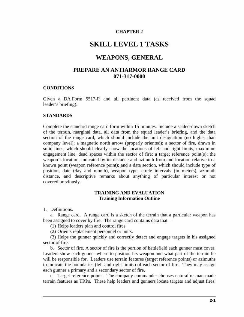
b. Unsupported grips. You may use any of three nonfiring hand grips to support your firing hand (Figures 3, 4, and 5). (1) Fist grip (Figure 3). Begin by gripping the weapon as previously described (Task Step 3). Firmly close the fingers of your nonfiring hand over the fingers of your firing hand. Make sure the index finger of your nonfiring hand is between the middle finger of your firing hand and the guard. Place your nonfiring thumb beside your firing thumb.
STP 7-11BCHM1-SM
2-26
NOTE: The M9 pistol has a recurved trigger guard, which allows you to place the index finger of your nonfiring hand on the front of the trigger guard, if you wish.
RECURVEREST FOR
FOREFINGER
Figure 3. Fist grip.
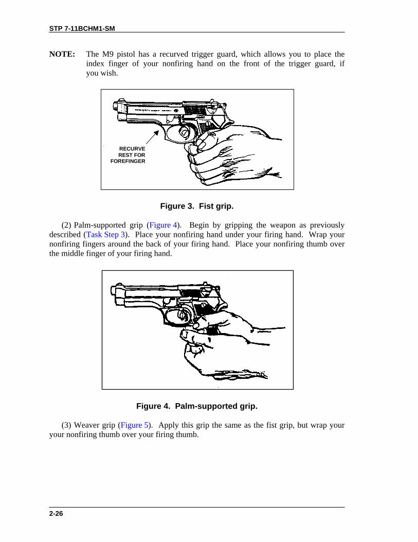
(2) Palm-supported grip (Figure 4). Begin by gripping the weapon as previously described (Task Step 3). Place your nonfiring hand under your firing hand. Wrap your nonfiring fingers around the back of your firing hand. Place your nonfiring thumb over the middle finger of your firing hand.
Figure 4. Palm-supported grip.
(3) Weaver grip (Figure 5). Apply this grip the same as the fist grip, but wrap your your nonfiring thumb over your firing thumb.

STP 7-11BCHM1-SM
2-27
Figure 5. Weaver grip.
5. Select the most stable firing position with the best cover. Consider the following positions: a. Prone (Figure 6). To assume the prone position— (1) Lie flat on the ground, facing the target. (2) Extend your arms to the front, with your firing arm locked. (3) Wrap your nonfiring hand around either the wrist or the fingers of your firing hand. (4) Face forward. Keep your head down between your arms and behind the weapon.
Figure 6. Prone position.
b. Standing-with-support position (Figure 7). To assume this position— (1) Use available cover for support. For example, stand behind a tree or wall. (2) Stand behind a barricade, with your firing side in line with the edge of the barricade. (3) Place the palm of your nonfiring hand at eye level on the edge of the barricade, and extend your thumb past the edge of the barricade. (4) Lock the elbow of your firing arm. Rest your forearm on the extended thumb of your nonfiring hand. (5) Move the foot on your nonfiring side forward until your toe touches the bottom of the barricade. c. Kneeling (Figure 8). To assume this position—

STP 7-11BCHM1-SM
2-28
(1) Use available cover, such as a low wall, rocks, or a vehicle that you can fire over, for support. (2) Place your firing knee on the ground. Put your left knee down to fire left-handed, or your right knee down to fire right-handed. (3) Bend your other knee. Place the foot on your nonfiring side flat on the ground, pointing toward the target. Extend your arms over available cover and use it for support. (4) Lock the wrist and elbow of your firing arm. (5) Wrap your nonfiring hand around your firing fist or wrist to support your firing arm. NOTE: This position could silhouette you, making you a better target. When possible,
fire around the sides of walls, rocks, or vehicles instead of over them. d. Standing-without-support position (Figure 9). To assume this position— (1) Face the target. (2) Place your feet a comfortable distance apart. (3) Wrap your nonfiring hand around the fist or wrist of your firing hand. Lock the wrist and elbow of your firing arm toward the target. (4) Keep your body straight.
RIGHT HAND
FIRINGHAND
NONFIRINGHAND
LEFT HAND
Figure 7. Standing-with-support position.

STP 7-11BCHM1-SM
2-29
RIGHT-HANDEDFIRER
LEFT-HANDEDFIRER
Figure 8. Kneeling position.
POINT
PULL
Figure 9. Standing-without-support position.
e. Crouching (Figure 10). This position is the same as the standing-without-support position, except you must bend your knees slightly. Balance by leaning forward at the waist.

STP 7-11BCHM1-SM
2-30
6. Apply the fundamentals of marksmanship. a. Pistol grip. To obtain a proper pistol grip— (1) Place the pistol in the “V” formed by the thumb and forefinger of your firing hand. Line the sights up with your firing arm. Wrap your lower three fingers around the pistol. Grip with your middle finger under the trigger guard. Exert equal pressure on all three lower fingers to the rear, back through the wrist and forearm (Figure 1). (2) Rest your thumb on top of your middle finger when gripping the pistol. Do not exert any downward pressure. (3) Grip the pistol firmly, but not so firmly that your hand trembles.
Figure 10. Crouching position.
b. Sight alignment. To sight properly— (1) Align the front sight blade in the rear sight notch so that an equal amount of light shows on either side of the front sight. Ensure the top of the front and rear sight are even. (2) Relax as much as possible. (3) Maintain the correct sight alignment, and focus on the front sight. (4) Squeeze the trigger with a steadily increasing pressure straight to the rear, taking care not to disturb the sight alignment until after the hammer falls. NOTE: When there is more than one target, choose the target that presents the greatest
danger. This is often the closest target.
EVALUATION PREPARATION
Setup: Evaluate this task during daylight on a 9-MM Combat Pistol Qualification Course. Provide the soldier with 8 magazines and 52 rounds of live ammunition.
STP 7-11BCHM1-SM
2-31
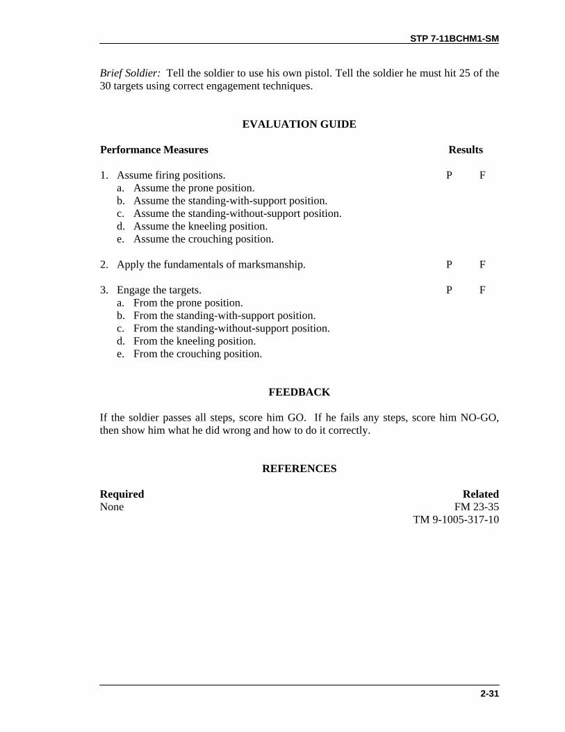
Brief Soldier: Tell the soldier to use his own pistol. Tell the soldier he must hit 25 of the 30 targets using correct engagement techniques.
EVALUATION GUIDE
Performance Measures
Results
1. Assume firing positions. a. Assume the prone position. b. Assume the standing-with-support position. c. Assume the standing-without-support position. d. Assume the kneeling position. e. Assume the crouching position.
P F
2. Apply the fundamentals of marksmanship.
P F
3. Engage the targets. a. From the prone position. b. From the standing-with-support position. c. From the standing-without-support position. d. From the kneeling position. e. From the crouching position.
P F
FEEDBACK
If the soldier passes all steps, score him GO. If he fails any steps, score him NO-GO, then show him what he did wrong and how to do it correctly.
REFERENCES
Required Related None FM 23-35 TM 9-1005-317-10

STP 7-11BCHM1-SM
2-32
CORRECT MALFUNCTIONS OF AN M9 PISTOL 071-004-0005
CONDITIONS Given an M9 pistol, loaded magazines with 9-mm ammunition, cleaner lubricant and preservative (CLP), lubricating oil arctic weather (LAW), lubricating oil semi-fluid (LSA), bore brush, wiping rags, M4 cleaning rod (handle with 1 section and a swab holder), and small arms cleaning swabs. STANDARDS Without damaging the pistol, eliminate malfunctions caused by faulty action of either the pistol or the ammunition while in an environment that requires engagement of targets.
TRAINING AND EVALUATION Training Information Outline
WARNINGDuring the following procedures always keep the pistolpointed in a safe direction.
1. Perform immediate action. a. When the slide is fully forward and the pistol fails to fire, apply immediate action as follows: (1) Ensure the safety lever is in FIRE position. (2) Squeeze the trigger again. (3) If the pistol does not fire, ensure that the magazine is fully seated, retract the slide to the rear, and release. (4) Squeeze the trigger. (5) If the pistol still does not fire, remove the magazine and retract the slide to eject the chambered cartridge. Insert a new magazine, retract the slide, and release to chamber another cartridge. (6) Squeeze the trigger. (7) If the pistol does not fire, replace the ammunition. (8) If the pistol fails to fire again, clear the pistol and perform remedial IAW step 2. b. When the slide is not fully seated forward, remove finger from the trigger. With the other hand, try to push the slide fully forward. If the slide will not move forward, proceed as follows: (1) Place safety lever in SAFE position. (2) Remove the magazine. (3) Grasp the slide and retract it to the rear, locking it with the slide stop. (4) Inspect the chamber and remove any obstructions. (5) Insert another loaded magazine into the pistol.
STP 7-11BCHM1-SM
2-33
(6) Release the slide. (7) Place the safety lever in the FIRE position, aim, and squeeze the trigger. (8) If pistol does not fire, clear the pistol and perform remedial action IAW step 2. 2. Perform remedial action. a. Ensure the pistol is clear. b. Disassemble the pistol and inspect for dirty, corroded, missing, or damaged parts. c. Clean dirty or corroded parts. Replace missing or damaged parts. d. Lubricate and assemble the pistol. e. Inspect magazine for damaged parts. Replace magazine if necessary. f. Check for dirty or damaged ammunition. Clean or replace ammunition. g. Perform a function check. h. Load the pistol and try to fire. i. If the pistol does not fire, clear the pistol and notify your supervisor.
EVALUATION PREPARATION
Setup: Provide equipment and materials listed in conditions. Use performance steps in the training outline to evaluate performance of the task.
Brief Soldier: Tell the soldier that the pistol has stopped firing. Tell the soldier to perform immediate and remedial action on the pistol.
EVALUATION GUIDE
Performance Measures
Results
1. Perform immediate action. P F
2. Perform remedial action. P F
FEEDBACK
If the soldier passes all steps, score him GO. If he fails any steps, score him NO-GO, then show him what he did wrong and how to do it correctly.
REFERENCES
Required Related None TM 9-1005-317-10

STP 7-11BCHM1-SM
2-36
M16A1/A2 RIFLE
CONSTRUCT FIELD-EXPEDIENT FIRING AIDS FOR AN M16A1 OR M16A2 RIFLE
071-311-2006
CONDITIONS
As a member of a squad in a defensive position, given an M16A1 or M16A2 rifle, a magazine and ammunition, sticks or rocks and boards available in the area, instructions on target location(s) within the individual’s sector of fire, and left and right limits of the sector. STANDARDS Properly emplace and align aiming and sector stakes on identifiable probable enemy avenues of approach, assault positions, and automatic weapons positions. Include left and right sector stakes to mark the sector of fire. When stakes are properly placed, they allow placement of rounds in selected target areas or positions. All fires are within the sector of fire.
TRAINING AND EVALUATION Training Information Outline
NOTES: 1. Use sector stakes to control the weapon within a sector of fire during
limited visibility. 2. Use aiming stakes to align a weapon on a known point or target during
limited visibility. 1. Sector stakes. Sector stakes mark the left and right limits of your sector of fire (Figure 1). a. Use tree limbs 1 to 1 1/2 inches in diameter or pieces of an ammunition box about 18 inches long for the sector stakes. b. Ensure the stakes are sturdy; they must stick out of the ground far enough to keep you from pointing and firing your rifle out of the sector. c. You must also drive the stakes far enough into the ground that the rifle will not knock them down if it hits them. 2. Aiming stakes. During limited visibility, aiming stakes help in placing fire on avenues of approach or on specific targets. a. Locate probable enemy positions or likely avenues of approach within your sector.

STP 7-11BCHM1-SM
2-37
b. Select forked tree limbs 12 to 14 inches long. c. Drive one stake into the ground near the edge of the fighting position. The stock of your rifle rests on this stake. The stake should be high enough to allow the rifle stock to fit comfortably against the gunner’s shoulder. d. Place additional stakes forward of the stock stake and align each with a target or avenue of approach. Firmly drive each stake into the ground. Adjust the stakes so that, in a firing position, when the rifle is placed on the stock and forward stakes, the fire will strike its intended target (Figure 2). To fire, hold your shoulder firmly against the butt plate and the barrel in the aiming stakes.
INDIVIDUAL SECTOROF FIRE
NOTCHED STAKEOR TREE CROTCH
LEFT LIMITSECTOR
STAKE
HORIZONTAL LOGOR BOARD
RIGHT LIMITSECTOR STAKE
Figure 1. Sector stakes.
POINT TARGET/AVENUE OF APPROACH
NOTCHEDSTAKESOR TREECROTCHES
Figure 2. Aiming stakes.
NOTE: The soldier must hold the weapon in the exact position he held it when he positioned the stakes.

STP 7-11BCHM1-SM
2-38
EVALUATION PREPARATION
Setup: At the test site, provide a prepared fighting position, an M16A1 or M16A2 rifle, one magazine with ammunition, forked stakes and sticks. Show the soldier his sector of fire and the target(s) to be laid on. Brief Soldier: Tell the soldier that he must emplace the M16A1 or M16A2 rifle using the field-expedient method with the materials provided.
EVALUATION GUIDE
Performance Measures
Results
1. Emplace the sector stakes so that the rifle cannot be fired outside theassigned sector of fire, and so that the stakes cannot be knocked downwhen touched with the rifle.
P F
2. Emplace the aiming stakes so each target is hit when the rifle is fired. The aiming stakes should provide a stable rest for the rifle.
P F
FEEDBACK
If the soldier passes all steps, score him GO. If he fails any steps, score him NO-GO, then show him what he did wrong and how to do it correctly.
REFERENCES
Required Related TM 9-1005-317-10 FM 21-75
STP 7-11BCHM1-SM
2-39
ZERO A NIGHT VISION SIGHT AN/PVS-4 TO AN M16A1 OR M16A2 RIFLE
071-315-2307 CONDITIONS Given an AN/PVS-4 mounted on a zeroed M16A1 or M16A2 rifle, a magazine with 18 rounds of ammunition, a silhouette target (with a 25-meter zeroing target attached) 25 meters from the firing point, and sandbags. NOTE: Ensure that the AN/PVS-4 has the M16 M203 sight reticle installed. STANDARDS Place the center of a three-round shot group 7 centimeters below the target aiming point. NOTE: You may zero the sight during daylight or dark. If in daylight, use the
daylight cover.
TRAINING AND EVALUATION Training Information Outline
CAUTIONProlonged use of the sight under high light without a daylightcover will damage the image-intensifier assembly.
1. Assume a good prone-supported position 25 meters from the target. 2. Place the sight into operation (see Task 071-315-0003, Operate a Night Vision Sight AN/PVS-4).
WARNINGTo prevent eye injury from weapon recoil, attach theeyeguard to the sight before firing your weapon.
3. Adjust the azimuth and elevation controls so that the reticle aiming point is about in the center of the sight’s field of view. 4. Fire three rounds to seat the sight on your weapon. Fire the rounds into a safe area; try not to hit the zero target. Retighten the mounting knob.

STP 7-11BCHM1-SM
2-40
5. Place the zeroing range aiming point of the reticle on the target aiming point; fire three rounds to obtain a good shot group (Figure 1). Use either the M16A1 25-meter zero target (NSN 6920-01-167-1392) shown in Figure 2 or the M16A2 25-meter zero target (NSN 6920-01-253-4005) shown in Figure 3. When zeroing the night vision sight, you can use either of these targets with either the M16A1 or M16A2 rifle. Use the marginal information on the target to adjust the sights on the rifle—not the night vision sight.
AIMING POINT0 TO 250 METERS
AIMING POINT 400METERS
AIMING POINT 500METERS
Figure 1. Zero aiming point.
6. Locate the center of the shot group. From the center of the group, adjust the reticle to move the center of the shot group to a point 7 centimeters (10 1/2 squares on the M16A1 target; 7.8 squares on the M16A2 target) directly below the target aiming point (Figure 2 and Figure 3). Mark the reticle adjustment actuators to show the direction of round impact movement. a. Each click of the azimuth or elevation adjustment actuator moves the strike of the round 0.63 centimeter (1/4 mil or about 1/4 inch) at a 25-meter range. b. On the M16A1 zero target, 1 1/2 squares equals 1 centimeter and 10 1/2 squares equals 7 centimeters (Figure 2). On the M16A2 zero target, each square is .9 centimeter and 7.8 squares equals 7 centimeters (Figure 3). 7. Perform the following actions after you adjust the controls: a. Move the weapon so that the reticle aiming point is again on the target aiming point. b. Repeat Task Step 5 and Task Step 6 until the center of the shot group is 7 centimeters below the target aiming point as shown in Figure 4 and Figure 5. 8. During zeroing, make sure the soldier places the reticle aiming point (Figure 1) on the target aiming point in the silhouette’s center of mass. Figure 6 shows what a zeroed shot group should look like.

STP 7-11BCHM1-SM
2-41
Figure 2. M16A1 zeroing target.
Figure 3. M16A2 zeroing target.
EXAMPLE: From the center of the shot group in Figure 4, move theazimuth adjustment actuator 11 clicks to the left. • Move the elevation adjustment actuator down 17 clicks. • From the center of the shot group in Figure 5, move the azimuth
adjustment actuator 9 clicks to the left. Move the elevation adjustment actuator 16 clicks.

STP 7-11BCHM1-SM
2-42
Figure 4. Sample 25-meter zeroing target for M16A1.
Figure 5. Sample 25-meter zeroing target for M16A2.

STP 7-11BCHM1-SM
2-43
Figure 6. Sight picture and zeroed shot group.
EVALUATION PREPARATION
Setup: At the test site, provide all equipment and materials given in the task conditions statement. Also provide a bipod for the rifle. Brief Soldier: Tell the soldier to zero the AN/PVS-4 to the rifle within 18 rounds or less.
EVALUATION GUIDE
Performance Measures
Results
1. Place the AN/PVS-4 sight into operation.
P F
2.. Zero the AN/PVS-4 sight to the rifle using 18 rounds or less.
P F
3. Remove the AN/PVS-4 sight from operation. P F
FEEDBACK If the soldier passes all steps, score him GO. If he fails any steps, score him NO-GO, then show him what he did wrong and how to do it correctly.

STP 7-11BCHM1-SM
2-44
REFERENCES Required Related None TM 11-5855-213-10

STP 7-11BCHM1-SM
2-45
ENGAGE TARGETS WITH AN M16A1 OR M16A2 RIFLE USING A NIGHT VISION SIGHT AN/PVS-4
071-315-2308 CONDITIONS During darkness, given an M16A1 or M16A2 rifle with a mounted and zeroed AN/PVS-4; one silhouette target between 50 and 100 meters, one at 150 meters, and one between 200 and 250 meters; and one magazine with 18 rounds of ammunition. STANDARDS Fire all 18 rounds and hit the targets at least nine times. At least five rounds must hit the 150-meter target; at least two rounds must hit the 50- to 100-meter target, and at least two rounds must hit the 200- to 250-meter target.
TRAINING AND EVALUATION
Training Information Outline
NOTE: Ensure the AN/PVS-4 has the proper sighting reticle (Figure 1).
M16A1 AIMING POINTS
RANGE SCALE
Figure 1. Sight reticle.
1. Place the sight into operation (see Task 071-315-0003, Operate a Night Vision Sight AN/PVS-4). 2. Use the sight reticle. When used with the rifle, the AN/PVS-4 sight reticle consists of two parts (Figure 1). a. Use the upper part of the reticle (range scale) to determine range to the target. b. Use the lower part of the reticle to aim the weapon.

STP 7-11BCHM1-SM
2-46
NOTE: Ensure the AN/PVS-4 is mounted to the rifle using the rifle mounting adapter and not the M203 mounting bracket.
3. Determine range to target. a. The vertical lines on the range scale tell how far away a 6-foot man is. (1) Place the target on the horizontal line and match it with one of the vertical lines (A, Figure 2). (2) Read the number at the bottom or top of the vertical line. That is the distance in hundreds of meters to the target. (3) If the figure is the same height as the vertical line above and below the horizontal line, the distance is half of the number at the top or bottom of that line (B, Figure 2). (4) The man shown in A, Figure 2 is 400 meters away; the man in B, Figure 2 is 500 meters away.
A B
Figure 2. Range determination using vertical lines.
b. The horizontal line of the range scale indicates the range (in hundreds of meters) of a 20-foot target such as a tank or large truck viewed from the side. (1) Place the left edge of the vehicle at the left side of the horizontal line (Figure 3). (2) Read the range to the tank from the scale at the right edge of the tank. As shown in A, Figure 3, the range to the vehicle is 1,000 meters. (3) When viewed from the front or rear, the vehicle width equals about half its length. Read the placement of the vehicle width on the range scale as half the range scale value. As shown in B, Figure 3, the range to the vehicle is 400 meters. 4. Engage targets using the sight reticle. a. The rifle aiming point for ranges out to 250 meters is the center of the three straight lines (zero aiming point) (Figure 4). The top of the vertical line is the aiming point for 400 meters, and the bottom of the line is the aiming point for 600 meters. b. Locate the target, estimate the range, and place the proper aiming point on the target.

STP 7-11BCHM1-SM
2-47
WARNINGTo prevent eye injury from weapon recoil, attach the eyeguard to the sight before firing the weapon.
c. Fire the weapon using correct marksmanship procedures.
4 4
6 6
10 10
8 8
A B
Figure 3. Range determination using horizontal line.
NOTE: When firing the rifle, disregard the three dots to the right of the aiming point;
you would only need these if you were firing the M203.
AIMING POINT0 TO 250 METERS
AIMING POINT400 METERS
AIMING POINT600 METERS
Figure 4. Zero aiming point.
EVALUATION PREPARATION
Setup: At a live-fire range, provide the equipment and materials given in the task conditions statement. Turn off the sight after evaluation.

STP 7-11BCHM1-SM
2-48
Brief Soldier: Tell the soldier to engage all targets with a minimum of 9 hits out of 18 rounds.
EVALUATION GUIDE
Performance Measures
Results
1. Place the AN/PVS-4 into operation.
P F
2. Engage targets. a. The 150-meter target with at least five hits. b. The 50- to 100-meter target with at least two hits. c. The 200- to 250-meter target with at least two hits.
P F
FEEDBACK
If the soldier passes all steps, score him GO. If he fails any steps, score him NO-GO, then show him what he did wrong and how to do it correctly.
REFERENCES
Required Related None TM 11-5855-213-10

STP 7-11BCHM1-SM
2-49
M249 MACHINE GUN
MAINTAIN AN M249 MACHINE GUN 071-312-4025
CONDITIONS Given an M249 machine gun; linked 5.56-mm ammunition; cleaning kit with pipe cleaners, small arms swabs, chamber and bore brushes, cleaning rod, wiping rags, scraper tool, and cleaner lubricant preservative (CLP). You have a requirement to maintain the weapon. STANDARDS Clean and lubricate the M249 machine gun. Inspect parts. Turn in unserviceable parts. Assemble the gun and ensure it is operational. Clean and inspect linked 5.56-mm ammunition for serviceability. Turn in unserviceable ammunition.
TRAINING AND EVALUATION
Training Information Outline
NOTE: The M249 is available with old and new style barrels. Diagrams used here show the new-style barrel.
1. Clear the M249 machine gun. a. Move the safety to the fire position. b. With your right hand, palm up, pull the cocking handle to the rear and lock the bolt to the rear. c. Hold the cocking handle to the rear and move the safety to the safe position. Push the cocking handle forward to the locked position. Place weapon on safe. d. Push the cocking handle forward to its lock position (you should hear a click). e. Raise the cover and feed mechanism assembly. To check for brass, links, or ammunition— (1) Check the feed pawl assembly under the feed cover. (2) Check the feed tray assembly. (3) Lift the feed tray assembly and inspect the chamber. (4) Check the space between the bolt assembly and chamber. (5) Insert two fingers in the magazine well and feel for brass or ammunition. f. Close the cover and feed mechanism assembly. Move the safety to the fire position. g. Pull the cocking handle to the rear, press the trigger, and ease the bolt forward. 2. Disassemble the M249 machine gun.

STP 7-11BCHM1-SM
2-50
WARNINGEnsure bolt is in forward position before removing drivespring, return rod, and transfer mechanism assembly.
a. Remove the drive spring, return rod, and transfer mechanism assembly. (1) Raise the cover assembly. Pull the upper retaining pin at the rear of the receiver to the left. Let the butt pivot downward so that the rear opening of the receiver is clear (Figure 1).
NOTE: The upper and lower retaining pins in the rear of the receiver are captured
pins. Do not try to remove them completely during disassembly.
Figure 1. Rear opening of the receiver.
(2) Hold the weapon with one hand on the buttstock. At the same time, push in and upward on the rear end of return rod and transfer mechanism assembly with thumb of other hand to release it from positioning groove. Withdraw return rod and transfer mechanism assembly and spring (Figure 2).

STP 7-11BCHM1-SM
2-51
Figure 2. Removal of the return rod and transfer mechanism assembly.
(3) Separate the spring from the return rod and transfer mechanism assembly (Figure 3).
Figure 3. Removal of the spring.
b. Remove the operating rod, slide assembly, and bolt assembly. (1) Pull the cocking handle to the rear to move operating rod, slide assembly, and bolt assembly out the rear of the receiver (Figure 4).

STP 7-11BCHM1-SM
2-52
Figure 4. Removal of the operating rod, slide assembly, and bolt assembly.
(2) Rotate the bolt clockwise to disengage the lug. Remove the bolt from the slide assembly. Separate the piston from the slide assembly by pressing the rearmost retaining pin to the left and lifting the piston off the slide assembly (Figure 5).
SLIDEASSEMBLY
BOLT
RETAININGPIN
PISTON
CLEANINGROD SECTION
Figure 5. Removal of the bolt and piston.
c. Remove the heat shield. Hold the weapon with one hand. With the other hand, grasp the heat shield just forward of the barrel handle, and lift it off the barrel (Figure 6).

STP 7-11BCHM1-SM
2-53
Figure 6. Removal of the heat shield.
d. Remove the barrel (Figure 7). (1) Ensure the folding handle on the new style barrel is in carrying (up) position. (2) Depress the barrel locking lever with your left hand. Grasp and lift the carrying handle with your right hand. Push the barrel forward.
Figure 7. Removal of the barrel.
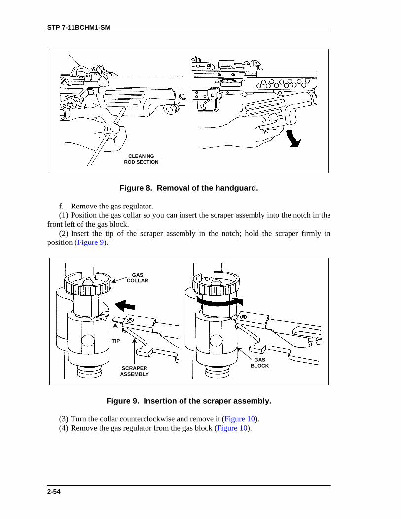
e. Remove the handguard (Figure 8). (1) Push the handguard retaining pin to the left using a section of the cleaning rod. (2) Pull downward and remove the handguard.
STP 7-11BCHM1-SM
2-54
CLEANINGROD SECTION
Figure 8. Removal of the handguard.
f. Remove the gas regulator. (1) Position the gas collar so you can insert the scraper assembly into the notch in the front left of the gas block. (2) Insert the tip of the scraper assembly in the notch; hold the scraper firmly in position (Figure 9).
GASCOLLAR
GASBLOCKSCRAPER
ASSEMBLY
TIP
Figure 9. Insertion of the scraper assembly.
(3) Turn the collar counterclockwise and remove it (Figure 10). (4) Remove the gas regulator from the gas block (Figure 10).

STP 7-11BCHM1-SM
2-55
Figure 10. Removal of the gas regulator from the gas block.
g. Remove the buttstock and buffer assembly. NOTE: The upper and lower retaining pins in the rear of the receiver are captured
pins. Do not try to remove them completely during disassembly. (1) Using a section of the cleaning rod, push the lowermost retaining pin to the left. (2) While supporting the trigger mechanism with one hand, use the other to pull the buttstock and buffer assembly rearward and remove it (Figure 11).

STP 7-11BCHM1-SM
2-56
CLEANINGROD SECTION
Figure 11. Removal of the buttstock and buffer assembly.
h. Remove the trigger mechanism by pulling rearward and down (Figure 12).
TRIGGERMECHANISM
Figure 12. Removal of the trigger mechanism.
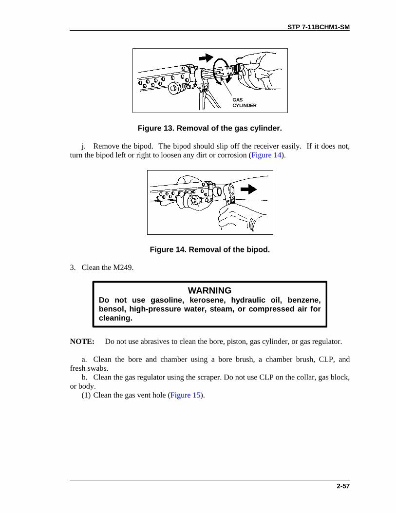
i. Remove the gas cylinder. (1) Turn the gas cylinder to the left or right to release the locking spring. (2) Pull the gas cylinder forward to remove it (Figure 13).
STP 7-11BCHM1-SM
2-57
GASCYLINDER
Figure 13. Removal of the gas cylinder.
j. Remove the bipod. The bipod should slip off the receiver easily. If it does not, turn the bipod left or right to loosen any dirt or corrosion (Figure 14).
Figure 14. Removal of the bipod.
3. Clean the M249.
WARNINGDo not use gasoline, kerosene, hydraulic oil, benzene,bensol, high-pressure water, steam, or compressed air forcleaning.
NOTE: Do not use abrasives to clean the bore, piston, gas cylinder, or gas regulator. a. Clean the bore and chamber using a bore brush, a chamber brush, CLP, and fresh swabs. b. Clean the gas regulator using the scraper. Do not use CLP on the collar, gas block, or body. (1) Clean the gas vent hole (Figure 15).

STP 7-11BCHM1-SM
2-58
GAS VENTHOLE
Figure 15. Cleaning the gas vent hole.
(2) Clean the central hole of the gas regulator with the appropriate part of the scraper by turning the scraper clockwise and pushing it inward toward the bottom of the housing (Figure 16).
Figure 16. Cleaning the central hole.
(3) Clean the two grooves of the regulator body using the protruding tips of the scraper (Figure 17).

STP 7-11BCHM1-SM
2-59
Figure 17. Cleaning the grooves of the regulator body.
c. Clean the gas cylinder and piston using the scraper. Do not use CLP on the gas cylinder or on the piston. (1) Clean the front interior of the gas cylinder (repositioned in receiver with bipod in place) by inserting and turning the flat side of the scraper in a full 360-degree circular motion (Figure 18).
Figure 18. Cleaning the gas cylinder’s front interior.
(2) Clean the internal grooves on the front side of the gas cylinder as previously described (using the protruding tips of the scraper), but insert the scraper farther into the gas cylinder (Figure 19).
Figure 19. Cleaning the gas cylinder’s internal grooves.

STP 7-11BCHM1-SM
2-60
(3) Clean the three grooves of the piston using a full, 360-degree circular motion (Figure 20).
Figure 20. Cleaning the grooves of the piston.
(4) Clean the hole in the front of the piston by inserting and turning the flat side of the scraper in a full 360-degree circular motion (Figure 21).
Figure 21. Cleaning the hole in the piston.
d. Remove carbon and dirt from all other parts of the weapon using CLP and a wiping rag. e. Clean ammunition boxes with a brush and clean dry wiping rag. f. Clean ammunition with a clean dry wiping rag. 4. Inspect the M249 machine gun. a. Inspect the bore and chamber for chips and pitting. b. Check the front sight for looseness. c. Inspect the flash suppressor (old style barrel) or compensator (new style barrel), the barrel extension, and the barrel release for cracks, dents, burrs, or other damage. d. Check the cover assembly for smooth operation, spring tension, bent parts, and excessive wear. e. Check the cocking assembly for free movement and for bent or cracked parts. f. Check the rails for excessive wear, burrs, and chips. g. Check the barrel locking latch and cover detent springs for spring tension.

STP 7-11BCHM1-SM
2-61
h. Check for broken pistol grip and chipped or cracked trigger housing holding lug. i. Check the tripping lever and the sear for burrs, cracks, chips, or wear. j. Check the cocking action by pushing back on the tripping lever; the sear should rise. Pull the trigger; the sear should lower. k. Check the safety function. Push the safety to the right (RED BAND NOT VISIBLE). Pull the trigger; the sear will not lower. Push the safety to the left (RED BAND VISIBLE). Pull the trigger again; the sear will lower. l. Check the slide assembly, bolt assembly, piston assembly and return rod and transfer mechanism assembly for burrs, cracks, and broken pins. Push down on roller of slide assembly to ensure it retracts. Check the driving spring for broken strands. m. Check bipod legs for correct operation. n. Check the rear sight assembly for serviceability. o. Check the ammunition box for damage. Make sure the box latch will engage the receiver dovetail. p. Inspect ammunition. (1) Check for damaged, corroded, or loose bullets. (2) Check for damaged links. (3) Report to your squad leader or NCOIC any deficiencies you cannot correct. 5. Lubricate the M249. NOTE: Use only CLP on the M249. a. Lubricate exposed metal parts and all moving parts with a light coat of CLP. b. Do not lubricate the gas regulator hole in the barrel or the gas regulator itself. 6. Assemble the M249. a. Replace the bipod and gas cylinder. (1) Place the bipod on the receiver. (2) Push the gas cylinder through the bipod yoke into the receiver. (3) Push the cylinder to the rear while countering the pressure of the locking spring and guiding the end of the cylinder into the receiver with the other hand applying downward pressure. When you have fully inserted the gas cylinder, rotate it until the spring clicks into place in the recess at the rear of cylinder (Figure 22).

STP 7-11BCHM1-SM
2-62
POSITION RECESS INCYLINDER NEAR SPRING.
Figure 22. Replacement of the bipod and gas cylinder.
b. Replace the handguard. (1) Stow cleaning equipment in the handguard. (2) Place the handguard onto the receiver and slide it backward until it stops. (3) Using a cleaning rod section, push the handguard retaining pin to the right. This locks the handguard into position (Figure 23).
Figure 23. Replacement of the handguard.
(4) Pull downward on the handguard to ensure it locks into position. c. Replace the gas regulator. (1) Insert the gas regulator into the lower end of the hole in the gas block. Align the notch on the gas regulator body with the notch in the gas block (Figure 24).

STP 7-11BCHM1-SM
2-63
NOTCH
Figure 24. Replacement of the gas regulator.
(2) With gas regulator installed and supported on a firm surface, place the gas collar on the protruding end of the gas regulator. Rotate the gas collar until it slips in place. To lock the gas regulator in place, press it in and rotate it (Figure 25).
OLD-STYLE COLLARDO NOT USE
OLD-STYLE COLLAR INNEW-STYLE BARREL; DOINGSO MAY UNDERPOWER THE
WEAPON
NEW-STYLE COLLARDO NOT USE
NEW-STYLE COLLAR INOLD-STYLE BARREL; DOINGSO MAY OVERPOWER THE
WEAPON
Figure 25. Replacement of the gas collar.

STP 7-11BCHM1-SM
2-64
WARNINGDO NOT switch the barrel assembly or the bolt assemblyback and forth from one machine gun to another withoutfirst checking the headspace. Doing so could injurepersonnel or damage the gun.
d. Replace the barrel. (1) Depress the barrel locking lever with your left hand (Figure 26).
Figure 26. Replacement of the barrel.
(2) Hold the carrying handle with your right hand; pull the barrel rearward into the receiver. Push the carrying handle downward and release the barrel locking lever. Check to ensure the barrel locks into position. e. Replace the trigger mechanism (Figure 27).
Figure 27. Replacement of trigger mechanism.
(1) Pull the retaining pin to the left side of the receiver.

STP 7-11BCHM1-SM
2-65
(2) Align the trigger mechanism with the slot on the bottom of the receiver. To hold the trigger mechanism in place, push the lower retaining pin into the right side hole on the rear of the trigger mechanism assembly. f. Replace the buttstock and shoulder assembly (Figure 28). Support the trigger mechanism with your left hand. Align the lower hole in buttstock and buffer assembly with the rear hole in the trigger mechanism. Push the lower retaining pin to the right.
Figure 28. Replacement of the buttstock and shoulder assembly.
g. Replace the operating rod, slide assembly, and bolt assembly. (1) Secure the slide assembly to the piston by pushing the retaining pin from the left to the right. Place the firing pin spring on the firing pin (Figure 29).
Figure 29. Attachment of the slide assembly to the piston.
(2) Put the bolt assembly into the slide assembly. Press in to compress the firing pin spring. Rotate the bolt and hook its driving lug into the slide assembly (Figure 30).

STP 7-11BCHM1-SM
2-66
FIRING PINSPRING
DRIVINGLUG
Figure 30. Attachment of the bolt assembly to the slide assembly.
(3) Put the assembled parts into the receiver with the feed cover open. Align and place the bolt lugs; slide the cutouts carefully onto the receiver rails. Press the trigger and at the same time, push the parts all the way forward (Figure 31).
Figure 31. Replacement of the operating rod, slide assembly, and bolt assembly.
h. Replace the spring, return rod, and transfer mechanism assembly. (1) Put the slide spring on the return rod and transfer mechanism assembly (Figure 32).

STP 7-11BCHM1-SM
2-67
Figure 32. Replacement of the spring.
(2) Ensure that the headed end of the vertical pin in the transfer mechanism assembly points upward (on top of the transfer mechanism assembly) (Figure 33).
HEADED PIN
Figure 33. Replacement of the return rod and transfer mechanism assembly.
(3) Hold the pistol grip with one hand. With the other hand, push the return rod and transfer mechanism assembly into its housing in the piston. Press inward and downward on the rear of the assembly until its two lugs move into the receiver grooves. i. Pivot the buttstock and buffer assembly upward into position. Push the retaining pin to the right, and close the cover assembly (Figure 34).
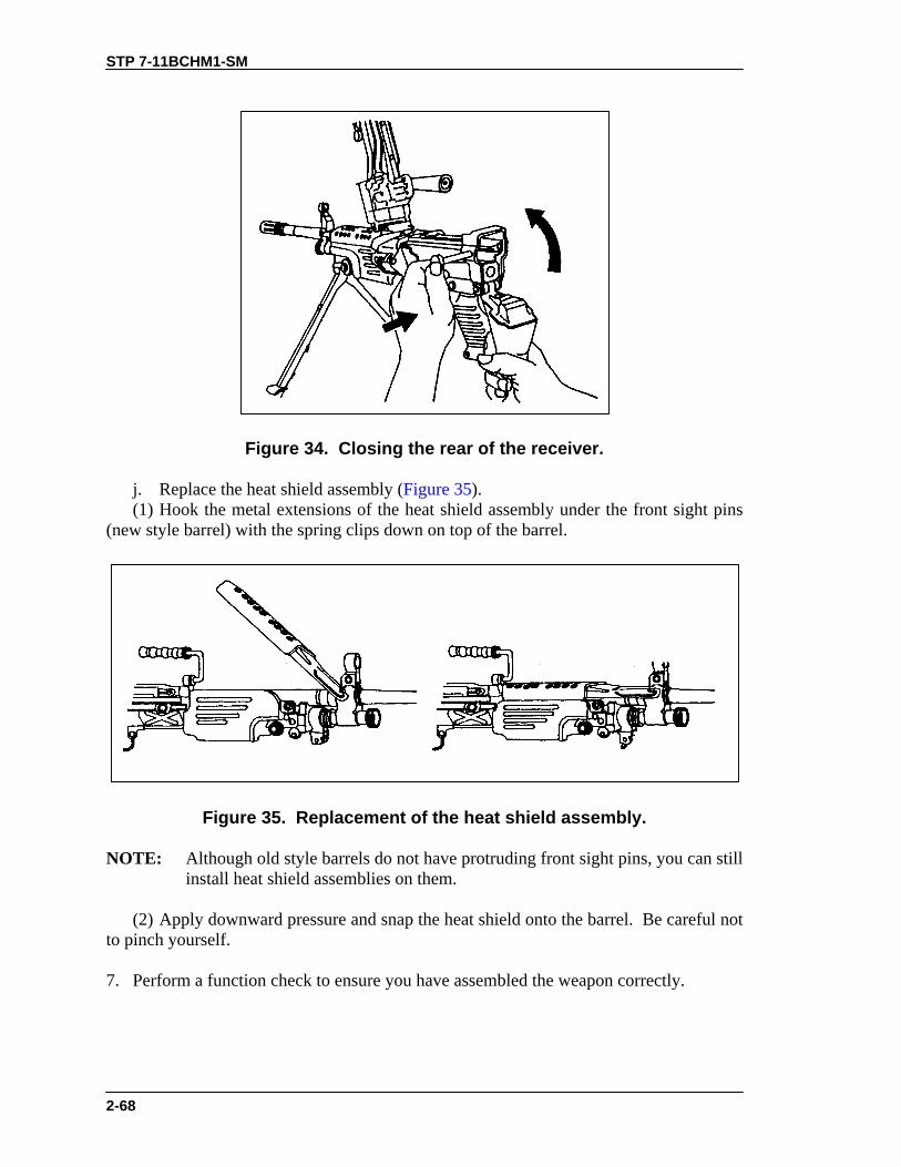
STP 7-11BCHM1-SM
2-68
Figure 34. Closing the rear of the receiver.
j. Replace the heat shield assembly (Figure 35). (1) Hook the metal extensions of the heat shield assembly under the front sight pins (new style barrel) with the spring clips down on top of the barrel.
Figure 35. Replacement of the heat shield assembly.
NOTE: Although old style barrels do not have protruding front sight pins, you can still install heat shield assemblies on them.
(2) Apply downward pressure and snap the heat shield onto the barrel. Be careful not to pinch yourself. 7. Perform a function check to ensure you have assembled the weapon correctly.
STP 7-11BCHM1-SM
2-69
EVALUATION PREPARATION
Setup: At the test site, provide all the equipment and materials listed in task conditions statement. Use only dummy ammunition for training purposes. Brief Soldier: Tell the soldier to perform maintenance on the M249, ammunition box, and linked 5.56-mm ammunition.
EVALUATION GUIDE
Performance Measures
Results
1. Clear the weapon.
P F
2. Disassemble the weapon without damaging any parts.
P F
3. Clean the weapon, ammunition box, and ammunition.
P F
4. Identify any damaged, worn, or malfunctioning part.
P F
5. Identify any damaged ammunition.
P F
6. Lubricate the weapon using the correct lubrication technique.
P F
7. Assemble the weapon in correct sequence without damaging any parts. P F
FEEDBACK
If the soldier passes all steps, score him GO. If he fails any steps, score him NO-GO, then show him what he did wrong and how to do it correctly.
REFERENCES
Required Related FM 23-14 None TM 9-1005-201-10

STP 7-11BCHM1-SM
2-70
PERFORM A FUNCTION CHECK ON AN M249 MACHINE GUN 071-312-4026
CONDITIONS Given an M249 machine gun and a requirement to perform a function check. STANDARDS Conduct an operational check of the M249 machine gun to make sure it is correctly assembled and functions properly.
EVALUATION PREPARATION
Setup: At the test site, provide the equipment listed in the task conditions statement. Brief Soldier: Tell the soldier to perform a function check to determine if the M249 machine gun functions properly.
EVALUATION GUIDE
Performance Measures
Results
1. Grasp cocking handle with the right hand, palm up, and pull the boltback, locking it to the rear.
P F
2. Push the cocking handle forward to the lock position.
P F
3. Place weapon on SAFE.
P F
4. Pull the trigger. The weapon should not fire.
P F
5. With the right hand, palm up, pull cocking handle to rear and hold it.
P F
6. Move the safety to fire position.
P F
7. While continuing to hold the cocking handle to the rear, use your lefthand to pull the trigger and ease the bolt forward to prevent damage tothe bolt.
P F

STP 7-11BCHM1-SM
2-71
FEEDBACK
If the soldier passes all steps, score him GO. If he fails any steps, score him NO-GO, then show him what he did wrong and how to do it correctly.
REFERENCES
Required Related None FM 23-14 TM 9-1005-201-10
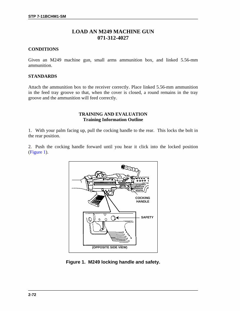
STP 7-11BCHM1-SM
2-72
LOAD AN M249 MACHINE GUN 071-312-4027
CONDITIONS Given an M249 machine gun, small arms ammunition box, and linked 5.56-mm ammunition. STANDARDS Attach the ammunition box to the receiver correctly. Place linked 5.56-mm ammunition in the feed tray groove so that, when the cover is closed, a round remains in the tray groove and the ammunition will feed correctly.
TRAINING AND EVALUATION Training Information Outline
1. With your palm facing up, pull the cocking handle to the rear. This locks the bolt in the rear position. 2. Push the cocking handle forward until you hear it click into the locked position (Figure 1).
COCKINGHANDLE
(OPPOSITE SIDE VIEW)
SAFETY
Figure 1. M249 locking handle and safety.

STP 7-11BCHM1-SM
2-73
3. Push the safety from left to right for safe mode (the red band will not show) (Figure 1). 4. Open the cover, raise the feed tray assembly, and make sure the feed tray, receiver, and chamber area are clear (Figure 2). 5. Attach ammunition box with linked 5.56-mm ammunition to the underside of the receiver. To do so, align the box latch with the dovetail on the receiver (Figure 3). Pull outward on the ammunition box to make sure the aligning box latch engages. 6. Place the link belt in the feed tray with the first round against the cartridge stop and hold the belt in place. Close the cover assembly (Figure 4). NOTE: The cartridge indicator is no longer required, so you must remove it. If while
you are loading the weapon a cartridge indicator sticks up above the top of the left side of the cover, notify your supervisor or unit maintenance.
WARNINGThe weapon is now loaded.
COVER LATCHES(SQUEEZE TO OPENCOVER ASSEMBLY.)
Figure 2. Checking the feed tray, receiver, and chamber area.

STP 7-11BCHM1-SM
2-74
Figure 3. Attachment of the ammunition box.
CARTRIDGESTOP
FIRSTROUND
LEAD LINK TAB
Figure 4. Link belt in feed tray.
EVALUATION PREPARATION
Setup: Use dummy ammunition to test this task. At the test position, provide an M249 and a belt of linked, dummy 5.56-mm ammunition. For standardization, always make sure to place the bolt and cocking handle forward and the safety on safe. Make sure the ammunition is clean and linked properly. Have an assistant relink and wipe the ammunition clean before the next test. Brief Soldier: Tell the soldier to load the M249 machine gun.

STP 7-11BCHM1-SM
2-75
EVALUATION GUIDE
Performance Measures
Results
1. Lock the bolt in the rear position.
P F
2. Push the cocking handle forward to the locked position.
P F
3. Push the safety to safe position.
P F
4. Check to make sure the feed tray, receiver, and chamber are clear.
P F
5. Attach ammunition box with linked ammunition to the receiver.
P F
6. Place link belt in feed tray with first round against cartridge.
P F
7. Close the cover. P F
FEEDBACK
If the soldier passes all steps, score him GO. If he fails any steps, score him NO-GO, then show him what he did wrong and how to do it correctly.
REFERENCES
Required Related FM 23-14 None TM 9-1005-201-10

STP 7-11BCHM1-SM
2-76
UNLOAD AN M249 MACHINE GUN 071-312-4028
CONDITIONS Given an M249 machine gun, loaded with 5.56-mm ammunition (linked or in an M16 magazine), and a requirement to unload the M249. STANDARDS Remove all ammunition, expended brass, links, and magazine from the weapon
TRAINING AND EVALUATION Training Information Outline
EVALUATION PREPARATION
Setup: At the test site, provide the soldier with all the equipment given in the task conditions statement. You may evaluate this task using dummy 5.56-mm linked rounds or dummy 5.56-mm ammunition loaded in 30-round M16 magazines.
Brief Soldier: Tell the soldier that he must unload the M249 in the correct.
EVALUATION GUIDE
Performance Measures
Results
1. Pull the cocking handle to the rear, locking the bolt in the rear position.
P F
2. Place the safety on safe mode (the red band will not show) and returnthe cocking handle to its forward position.
P F
3. Remove ammunition and links. a. Belt-fed. Raise the cover and remove any ammunition or linksfrom the feed tray.
P F
b. Magazine-fed. Push down on the magazine release tab and pullthe magazine out. Then raise the cover.
4. Raise the feed tray and inspect the chamber to ensure that it containsno ammunition. If it contains ammunition, remove it.
P F

STP 7-11BCHM1-SM
2-77
EVALUATION GUIDE
Performance Measures
Results
5. Close the cover.
P F
6. Place the safety in the fire mode (the red band will show).
P F
7. Pull the cocking handle to the rear, and pull the trigger while manuallyeasing the bolt forward to the closed position.
P F
FEEDBACK
If the soldier passes all steps, score him GO. If he fails any steps, score him NO-GO, then show him what he did wrong and how to do it correctly.
REFERENCES
Required Related FM 23-14 None

STP 7-11BCHM1-SM
2-78
CORRECT MALFUNCTIONS OF AN M249 MACHINE GUN 071-312-4029
CONDITIONS Given a loaded M249 machine gun and 5.56-mm ammunition linked or loaded in an M16 magazine. The M249 machine gun has been firing and one of the following situations has developed: The weapon fails to fire; the weapon continues to fire after the trigger is released (in which case, the weapon is referred to as a “runaway weapon” and the fire is called “uncontrolled fire”); or the weapon fires sluggishly. STANDARDS For an M249 that fails to fire, take immediate action within 10 seconds to return the weapon to service without identifying the cause. If immediate action does not work, perform remedial action on either a hot or cold M249 and identify the cause of the malfunction. For an M249 that continues to fire after the trigger is released--that is, a “runaway” M249 firing “uncontrolled fire”--take immediate action to secure the weapon and identify the cause of the malfunction. For an M249 that fires sluggishly, take corrective action.
TRAINING AND EVALUATION Training Information Outline
1. Take immediate action to correct a failure to fire. a. Grasp the cocking handle (palm up) and pull it to the rear. b. Look at the ejection port to see if a cartridge case, belt link, or round ejects. (1) If nothing ejects-- (a) Lock the bolt to the rear. (b) Return the cocking handle forward. (c) Proceed to Step 2 or 3 to take remedial action. (2) If a cartridge, belt link, or round ejects-- (a) Return the cocking handle to the forward position. (b) Aim and fire the weapon at the target. (c) If the weapon does not fire, place it in safe mode, and proceed to Step 2 or 3 to take remedial action. 2. Take remedial action on a cold weapon (one that has fired less than 200 rounds in two minutes). a. Ensure the cocking handle is forward and the weapon is in the safe mode. b. Keep the weapon oriented on the target area. Ensure your face is not directly over the feed cover. c. Raise the feed cover.

STP 7-11BCHM1-SM
2-79
d. If the weapon still does not fire, remove the ammunition belt or magazine. (1) If no rounds are in the chamber-- (a) Reload and try to fire at the target. If the weapon fires, the stoppage has been corrected. (b) If the weapon fails to fire, take immediate action (Step 1). If the weapon still fails to fire, continue to the next step. (c) Clear the weapon. (d) Disassemble and inspect the weapon. (e) Clean, lubricate, and replace damaged or missing parts as needed. (2) If a cartridge is in the chamber-- (a) Remove all ammunition from the feed tray and close the cover. (b) Try to fire. If the weapon fires, the stoppage has been corrected. Reload and continue the mission. (c) If the weapon does not fire, continue to the next step. (d) Lock the bolt to the rear. (e) With the cover closed, remove the round from the chamber using a cleaning rod. (f) Clear the weapon. (g) Disassemble and inspect the weapon. (h) Clean, lubricate, and replace damaged or missing parts as needed. 3. Take remedial action on a hot weapon (one that has fired more than 200 rounds in two minutes). a. Ensure the cocking handle is forward and the weapon is in the safe mode. b. Keep the weapon oriented on the target area. Place the safety in the safe mode.
WARNINGDuring training, wait fifteen minutes before applyingremedial action. During combat, wait five seconds beforeapplying remedial action due to the possibility that a“hangfire” or “cookoff” may occur.
c. Raise the cover. d. Remove the ammunition belt or magazine. e. Raise the feed tray. f. Inspect the chamber. (1) If no round is in the chamber— (a) Reload and try to fire. (b) If the gun fires, the stoppage has been corrected. (c) If the weapon fails to fire, apply immediate action for a second time. (d) If immediate action does not work, continue to the next step. (e) Disassemble and inspect the weapon. (f) Clean, lubricate, and replace damaged or missing parts, as needed. (2) If a round is in the chamber— (a) Close the cover and try to fire.
STP 7-11BCHM1-SM
2-80
(b) If the weapon fires, the stoppage has been corrected. (c) If the weapon does not fire, ensure the cocking handle is forward and the weapon is in the safe mode. (d) Disassemble and inspect the weapon. (e) Clean, lubricate, and replace damaged or missing parts, as needed. 4. Take immediate action to secure a runaway weapon. a. If after the trigger is released, the weapon continues to fire, take one of the following actions: (1) Hold the weapon on the target until the weapon stops firing. (2) Break the ammunition belt by twisting it in either direction. (3) Allow the weapon to fire the remaining ammunition at the target. b. Clear the weapon. c. Disassemble the weapon and check for the following deficiencies: (1) Broken, worn, or burred sear. (2) Worn sear notch on the piston assembly. (3) Sear stuck in the trigger housing. (4) Carbon buildup in the gas system. d. Clean, lubricate, and replace damaged or missing parts as required. e. Turn weapon in to maintenance before firing again. 5. Correct sluggish operation of the M249 Machine Gun. a. Clear the weapon. b. Disassemble and inspect the weapon. c. Clean, lubricate, and replace damaged or missing parts as required.
EVALUATION PREPARATION Setup: At the test site or live-fire range, provide all the equipment given in the task conditions statement. Set up the weapon so that it is loaded and in the safe mode. Insert an expended round in the belt to cause a stoppage. You can evaluate this task using dummy 5.56-mm ammunition either in links or in M16 magazines. Brief Soldier: Tell the soldier that he must assume a firing position behind the M249 to apply any required immediate action. Ask the soldier to describe the actions to perform for remedial action on a cold and hot weapon, a sluggishly operating weapon, and a runaway weapon.
EVALUATION GUIDE Performance Measures
Results
1. Take immediate action to correct a failure to fire.
P F

STP 7-11BCHM1-SM
2-81
EVALUATION GUIDE Performance Measures
Results
2. Take remedial action on a cold weapon.
P F
3. Take remedial action on a hot weapon.
P F
4. Take immediate action to secure a runaway weapon.
P F
5. Correct sluggish operation of the M249. P F
FEEDBACK If the soldier passes all steps, score him GO. If he fails any steps, score him NO-GO, then show him what he did wrong and how to do it correctly.
REFERENCES Required Related FM 23-14 None

STP 7-11BCHM1-SM
2-82
LAY AN M249 MACHINE GUN USING FIELD-EXPEDIENT METHODS
071-312-4004 CONDITIONS Given an M249 machine gun, linked 5.56-mm ammunition, a defensive fighting position, a designated sector of fire, and notched stakes or tree crotches. STANDARDS In the designated sector of fire, lay an M249 machine gun using field-expedient methods to engage preselected targets and to define your sector limits.
TRAINING AND EVALUATION Training Information Outline
1. Fabricate notched stakes or tree crotches if needed (Figure 1).
LINE OF AIM FORPREDETERMINED TARGETS
TENTPEGS
NOTCHED STAKES, TREE CROTCHES,OR TENT POLES
Figure 1. Notched-stake or tree-crotch method of engaging predetermined targets.

STP 7-11BCHM1-SM
2-83
2. Aim the weapon at the preselected target(s). 3. Mark a spot on the ground under the buttstock assembly. 4. Move the weapon aside. Solidly drive a notched stake or tree crotch into the spot marked on the ground. 5. Place the stock of the weapon in the rests notched into the stakes or into the tree crotches. Make final adjustments to hit the desired target area and to define sector limits. NOTE: If you do not have any notched stakes or tree crotches, you can use tent poles
or strong sticks. You will need four poles or sticks for the left and right limits, and more for the target areas. Drive two poles or sticks in the ground in the shape of an “X.” Place the buttstock in the “X.”
6. Drive tent pegs in the ground slightly in front and behind the feet of the bipod legs. This will help you keep the weapon aligned in the sector of fire. Dig shallow trenches or grooves to allow the bipod feet to rotate when you move the stock from one stake or tree crotch to another.
EVALUATION PREPARATION Setup: Provide equipment and materials listed in the task conditions statement.
NOTE: During training, comply with unit SOP and any local regulations regarding the
cutting of live vegetation, the digging of holes, and the prevention of erosion.
Brief Soldier: Tell the soldier which target(s) to lay the gun on. Point out the sector that the soldier must cover by fire.
EVALUATION GUIDE Performance Measures
Results
1. Aim the weapon at preselected targets.
P F
2. Place the notched stakes or tree crotches to align weapon onpreselected targets.
P F
3. Drive tent pegs in the ground slightly in front and behind the feet of the bipod legs to help keep the weapon aligned on the sector of fire.
P F

STP 7-11BCHM1-SM
2-84
EVALUATION GUIDE Performance Measures
Results
4. Dig shallow trenches or grooves to permit the bipod feet to rotate asthe soldier moves the stock of the weapon from one stake or tree crotchto another.
P F
FEEDBACK If the soldier passes all steps, score him GO. If he fails any steps, score him NO-GO, then show him what he did wrong and how to do it correctly.
REFERENCES Required Related FM 23-14 None
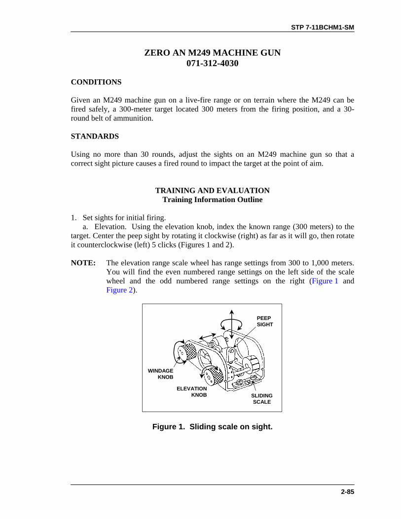
STP 7-11BCHM1-SM
2-85
ZERO AN M249 MACHINE GUN 071-312-4030
CONDITIONS Given an M249 machine gun on a live-fire range or on terrain where the M249 can be fired safely, a 300-meter target located 300 meters from the firing position, and a 30-round belt of ammunition. STANDARDS Using no more than 30 rounds, adjust the sights on an M249 machine gun so that a correct sight picture causes a fired round to impact the target at the point of aim.
TRAINING AND EVALUATION Training Information Outline
1. Set sights for initial firing. a. Elevation. Using the elevation knob, index the known range (300 meters) to the target. Center the peep sight by rotating it clockwise (right) as far as it will go, then rotate it counterclockwise (left) 5 clicks (Figures 1 and 2). NOTE: The elevation range scale wheel has range settings from 300 to 1,000 meters.
You will find the even numbered range settings on the left side of the scale wheel and the odd numbered range settings on the right (Figure 1 and Figure 2).
PEEPSIGHT
SLIDINGSCALE
ELEVATIONKNOB
WINDAGEKNOB
Figure 1. Sliding scale on sight.

STP 7-11BCHM1-SM
2-86
LATCH LATCH
BIPOD
LEG EXTENSION
Figure 2. Lowering the bipod.
b. Windage. Rotate the windage knob toward the muzzle until the peep sight is completely to the right; then rotate the windage knob toward the buttstock 12 clicks to the left. This will place the peep sight in the approximate center of the sight (Figures 1 and 2). 2. Assume a good stable firing position (Figure 3 and Figure 4).
LEGS A COMFORTABLE DISTANCEAPART, HEELS DOWN IF POSSIBLE
(HELMET INTENTIONALLY OMITTEDTO SHOW HAND POSITIONS)
NOTE: This is an example of the position and grip. If a soldierhas problems obtaining proper sight picture with this grip, heshould shift to a position that allows him a proper sight picture.
RIGHT CHEEK POSITIONED AGAINSTTHE FOREFINGER OF THE LEFT HAND
IMAGINARYLINE
Figure 3. Prone position, bipod-supported.

STP 7-11BCHM1-SM
2-87
Figure 4. Fighting position, bipod-supported.
3. Fire a three-round burst at the center base of the target. Note where the burst strikes. 4. Adjust sights so that rounds impact target area. a. Adjust the sights for deflection. Determine if the center of the beaten zone is left or right of the target. Adjust the windage knob forward to move it to the right, or adjust it rearward to move it to the left (Figure 5). b. Adjust the sights for elevation. Determine if the center of the beaten zone is above (high) or below (low) the point of aim. Rotate the peep sight clockwise to lower it, or counterclockwise to raise it (Figure 5).
100 meters — One click moves strike 5 cm (2 inches)
200 meters — One click moves strike 10 cm (4 inches)
300 meters — One click moves strike 15 cm (6 inches)
400 meters — One click moves strike 20 cm (8 inches)
500 meters — One click moves strike 25 cm (10 inches)
600 meters — One click moves strike 30 cm (12 inches)
700 meters — One click moves strike 35 cm (14 inches)
800 meters — One click moves strike 40 cm (16 inches)
900 meters — One click moves strike 45 cm (18 inches)
Figure 5. Windage and elevation (peep sight) correction chart.
5. Fire a confirming burst. (If you do not hit the target, repeat Steps 3 and 4 until you do so.
STP 7-11BCHM1-SM
2-88
6. Adjust the elevation scale to reflect the range to the target. 7. Record the zero. Once you have zeroed the weapon, record the elevation setting. a. Deflection. Do not record the adjustments for windage scale. Instead, loosen the windage sliding scale screws, and align the scale so that the large index line is under the windage mark on the sight. Tighten the screws. b. Elevation. Count the number of clicks (half turns) you have moved the peep sight away from the initial setting. For example, with a 300-meter zero, if you moved the peep sight two clicks (half turns) up, record ZERO 300 UP 2. If you moved the peep sight two clicks (half turns) down, record ZERO 300 DOWN 2.
EVALUATION PREPARATION Setup: At the test site, provide all equipment and materials in the task conditions statement. Brief Soldier: Indicate the target and the range to the target. Tell the soldier he has 30 rounds to zero the M249.
EVALUATION GUIDE Performance Measures
Results
1. Set the sights for initial firing.
P F
2. Assume a good stable firing position.
P F
3. Fire a three-round burst at the center base of the target, and note wherethe burst strikes.
P F
4. Adjust the sights so that rounds impact target area.
P F
5. Fire a confirming burst.
P F
6. Adjust the elevation scale to reflect the range to the target.
P F
7. Record the zero. Once you complete the zero, record theelevation setting.
P F

STP 7-11BCHM1-SM
2-89
FEEDBACK If the soldier passes all steps, score him GO. If he fails any steps, score him NO-GO, then show him what he did wrong and how to do it correctly.
REFERENCES Required Related FM 23-14 None TM 9-1005-201-10

STP 7-11BCHM1-SM
2-90
ENGAGE TARGETS WITH AN M249 MACHINE GUN 071-010-0006
CONDITIONS Given an M249 machine gun and linked 5.56-mm ammunition. STANDARDS Apply correct M249 machine gun target engagement techniques so that you hit each target in your assigned sector of fire.
TRAINING AND EVALUATION Training Information Outline
1. Assume a suitable firing position. Based on your situation, assume the position that will allow you to observe and engage targets, yet minimize your exposure to enemy fire. a. Bipod-supported prone. The bipod-supported prone position (Figure 1) and the bipod-supported fighting position (Figure 2) are the best positions for delivering effective fire on targets. Assume these positions when possible.
Figure 1. Bipod-supported prone position.
Figure 2. Bipod-supported fighting position.
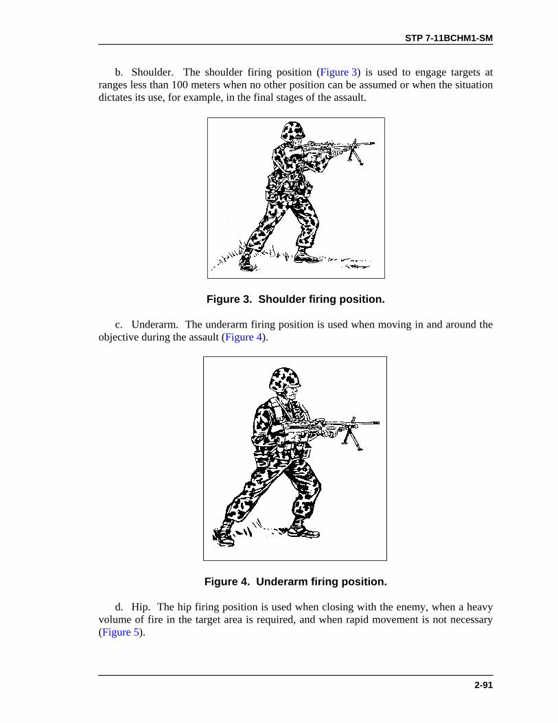
STP 7-11BCHM1-SM
2-91
b. Shoulder. The shoulder firing position (Figure 3) is used to engage targets at ranges less than 100 meters when no other position can be assumed or when the situation dictates its use, for example, in the final stages of the assault.
Figure 3. Shoulder firing position.
c. Underarm. The underarm firing position is used when moving in and around the objective during the assault (Figure 4).
Figure 4. Underarm firing position.
d. Hip. The hip firing position is used when closing with the enemy, when a heavy volume of fire in the target area is required, and when rapid movement is not necessary (Figure 5).
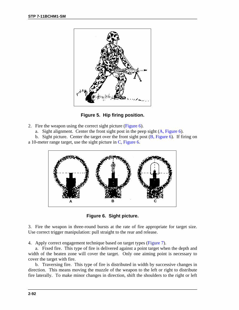
STP 7-11BCHM1-SM
2-92
Figure 5. Hip firing position.
2. Fire the weapon using the correct sight picture (Figure 6). a. Sight alignment. Center the front sight post in the peep sight (A, Figure 6). b. Sight picture. Center the target over the front sight post (B, Figure 6). If firing on a 10-meter range target, use the sight picture in C, Figure 6.
A B C
Figure 6. Sight picture.
3. Fire the weapon in three-round bursts at the rate of fire appropriate for target size. Use correct trigger manipulation: pull straight to the rear and release. 4. Apply correct engagement technique based on target types (Figure 7). a. Fixed fire. This type of fire is delivered against a point target when the depth and width of the beaten zone will cover the target. Only one aiming point is necessary to cover the target with fire. b. Traversing fire. This type of fire is distributed in width by successive changes in direction. This means moving the muzzle of the weapon to the left or right to distribute fire laterally. To make minor changes in direction, shift the shoulders to the right or left
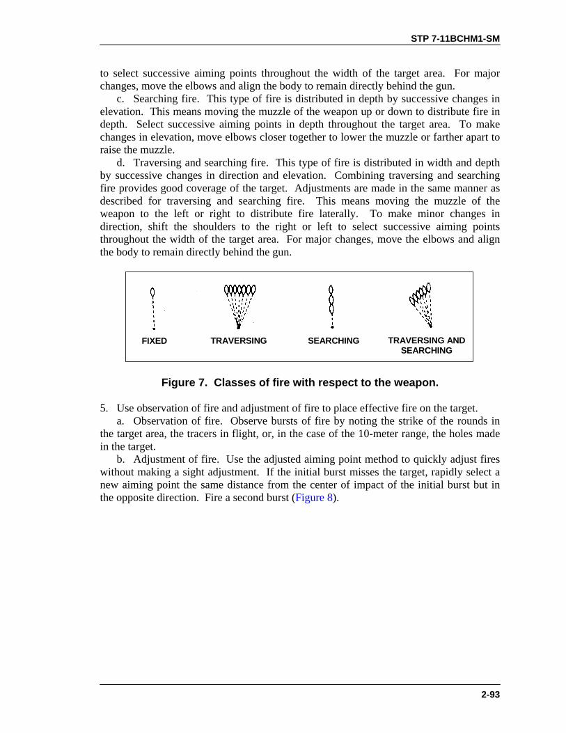
STP 7-11BCHM1-SM
2-93
to select successive aiming points throughout the width of the target area. For major changes, move the elbows and align the body to remain directly behind the gun. c. Searching fire. This type of fire is distributed in depth by successive changes in elevation. This means moving the muzzle of the weapon up or down to distribute fire in depth. Select successive aiming points in depth throughout the target area. To make changes in elevation, move elbows closer together to lower the muzzle or farther apart to raise the muzzle. d. Traversing and searching fire. This type of fire is distributed in width and depth by successive changes in direction and elevation. Combining traversing and searching fire provides good coverage of the target. Adjustments are made in the same manner as described for traversing and searching fire. This means moving the muzzle of the weapon to the left or right to distribute fire laterally. To make minor changes in direction, shift the shoulders to the right or left to select successive aiming points throughout the width of the target area. For major changes, move the elbows and align the body to remain directly behind the gun.
TRAVERSING ANDSEARCHING
SEARCHINGTRAVERSINGFIXED
Figure 7. Classes of fire with respect to the weapon.
5. Use observation of fire and adjustment of fire to place effective fire on the target. a. Observation of fire. Observe bursts of fire by noting the strike of the rounds in the target area, the tracers in flight, or, in the case of the 10-meter range, the holes made in the target. b. Adjustment of fire. Use the adjusted aiming point method to quickly adjust fires without making a sight adjustment. If the initial burst misses the target, rapidly select a new aiming point the same distance from the center of impact of the initial burst but in the opposite direction. Fire a second burst (Figure 8).

STP 7-11BCHM1-SM
2-94
BEATEN ZONE OFSUBSEQUENT BURST
BEATEN ZONEOF INITIALBURST
INITIALAIMING POINT
NEW AIMING POINT
Figure 8. Adjusted aiming point method.
6. Use correct application of fire to engage specific targets. a. Point target. Engage point targets with fixed fire (Figure 9). b. Area target. Initially, aim at the midpoint of the target area. Traverse and search to either flank, then back to the opposite flank (Figure 10).
Figure 9. Engagement of point target.
Figure 10. Engagement of area target.

STP 7-11BCHM1-SM
2-95
c. Linear target. Initially, aim at the midpoint of the target. Traverse fire to one flank and then to the other to cover the entire target (Figure 11). d. Deep target. Initially, aim at the midpoint of the target unless another portion of the target is more critical or presents a greater threat. Search down to one aiming point in front of the near end back up to one aiming point beyond the far end (Figure 12). e. Linear target with depth. Initially, aim at the midpoint of the target unless another portion of the target is more critical or presents a greater threat. Traverse and search to the flank closest to your position then back to the other to cover the entire target (Figure 13).
Figure 11. Linear target.
Figure 12. Deep target.

STP 7-11BCHM1-SM
2-96
Figure 13. Linear targets with depth.
f. Moving target. To hit a moving target, estimate the speed of the target and the lead required to fire and hit it, fire and track the target as it moves, adjust the lead by observing tracers and the strike of the bullets (Figure 14 and Figure 15).
RANGE OF TARGETSPEED IN
MILES PER HOUR 300 M 500 M 900 M
15 1/2 target length 1 target length 2 target lengths
Figure 14. Vehicle lead table.

STP 7-11BCHM1-SM
2-97
SPEED15 MPH
RANGE 300METERS
AWAYTOWARDSIDE VIEW
PERSONNEL
VEHICLE
Figure 15. Moving target aiming points.
EVALUATION PREPARATION Setup: Evaluate this task on a live-fire range by having the soldier fire Table IV in FM 23-14. Evaluate the soldier’s ability to use correct engagement techniques to engage specific types of targets. Provide the soldier with equipment and materials required to fire the course. Brief Soldier: Brief soldier on range safety per installation regulations. Tell the soldier to assume the bipod-supported prone position or bipod-supported fighting position. Tell the soldier you are evaluating both his ability to adjust fire and his ability to hit the target.
EVALUATION GUIDE Performance Measures
Results
1. Assume correct bipod-supported prone position or bipod-supported fighting position.
P F
2. Field zero on a 300-meter target with no more than 12 rounds.
P F
3. Engage single E-type silhouettes (point targets) at various ranges.
P F

STP 7-11BCHM1-SM
2-98
EVALUATION GUIDE Performance Measures
Results
4. Engage double E-type silhouettes (automatic weapon positions) atvarious ranges.
P F
5. Engage linear E-type silhouettes (troops on line) at various ranges. P F
FEEDBACK If the soldier passes all steps, score him GO. If he fails any steps, score him NO-GO, then show him what he did wrong and how to do it correctly.
REFERENCES Required Related FM 23-14 None

STP 7-11BCHM1-SM
2-99
MOUNT A NIGHT VISION SIGHT AN/PVS-4 ON AN M249 MACHINE GUN
071-010-0002 CONDITIONS Given a cleared M249 machine gun, an AN/PVS-4 mounting bracket assembly for the M249 machine gun, a night vision sight AN/PVS-4, and a requirement to mount the night vision sight AN/PVS-4 on the M249 machine gun. STANDARDS Attach and secure the mounting bracket assembly and night vision sight AN/PVS-4 to the M249 machine gun.
TRAINING AND EVALUATION Training Information Outline
CAUTIONWhen mounting an AN/PVS-4 nightsight on a mounting bracket,align the mounting screw hole on the sight so it fits flush againstthe mounting bracket locking screw. This prevents you fromstripping the threads when you tighten the mounting screw,which would prevent use of the nightsight with the M249.
1. Install the mounting bracket assembly (Figure 1). a. Hook the mounting bracket feet around the feed cover pin and position the bracket on top of the weapon. b. Turn the mounting bracket locking screw into the feed cover screw hole to secure the bracket. 2. Install the sight on the mounting bracket to the weapon. a. Place the sight on the mounting bracket. Align the mounting screw hole on the sight flush against the mounting bracket locking screw. b. Tighten the sight mounting bracket locking screw to secure the night sight to the bracket.

STP 7-11BCHM1-SM
2-100
HINGEPIN
COVERLOCKING
SCREWLOCATION
FEEDCOVERSCREWHOLE
Figure 1. Installation of mounting bracket assembly.
EVALUATION PREPARATION Setup: At the test site, provide the soldier with all the equipment given in the task conditions statement. Brief Soldier: Tell the soldier that he must mount night vision sight AN/PVS-4 on the M249 machine gun.
EVALUATION GUIDE Performance Measures
Results
1. Install the mounting bracket on the weapon.
P F
2. Install the nightsight on the mounting bracket. P F
FEEDBACK If the soldier passes all steps, score him GO. If he fails any steps, score him NO-GO, then show him what he did wrong and how to do it correctly.

STP 7-11BCHM1-SM
2-101
REFERENCES Required Related TM 11-5855-213-10 None FM 23-14

STP 7-11BCHM1-SM
2-102
ZERO A NIGHT VISION SIGHT AN/PVS-4 TO AN M249 MACHINE GUN
071-010-0001 CONDITIONS Given an M249 machine gun with a mounted AN/PVS-4, linked 5.56-mm ammunition, and engageable targets at 25 meters. STANDARDS Adjust the AN/PVS-4 so that the three round shot group hits the aiming point on the target.
TRAINING EVALUATION Training Information Outline
CAUTION
When using the nightsight in high light conditions, be sure to usethe daylight cover. This prevents the bright light from damagingthe nightsight's image intensifier.
NOTE: The sight may be zeroed during daylight or darkness. If zeroed during
daylight, the daylight cover must be used. 1. Procedures for zeroing the M249 machine gun. a. Make sure the reticle designed for use with the M249 machine gun is installed in the sight. b. Mark the selected target with the appropriate impact point. c. Place the selected target at a range of 25 meters. d. Place the sight in operation. Mount the sight to the weapon. Adjust the azimuth and elevation controls so that the reticle aiming point appears to be centered in the sight’s field of view (Figure 1). e. Fire a few rounds to seat the sight on the weapon. Retighten all mounting screws and knobs. f. Place the zeroing range aiming point of the reticle on the target aiming point. Fire enough rounds to obtain a good shot group. Locate the center of the shot group (Figure 2). g. Determine the distance (up/down and right/left) between the center of the shot group and the impact point on the target. h. Adjust the reticle to move the center of the shot group the measured distance to the impact point. Repeat steps f and g until the impact point on the target is at the center of the shot group. The sight is now zeroed to the weapon.
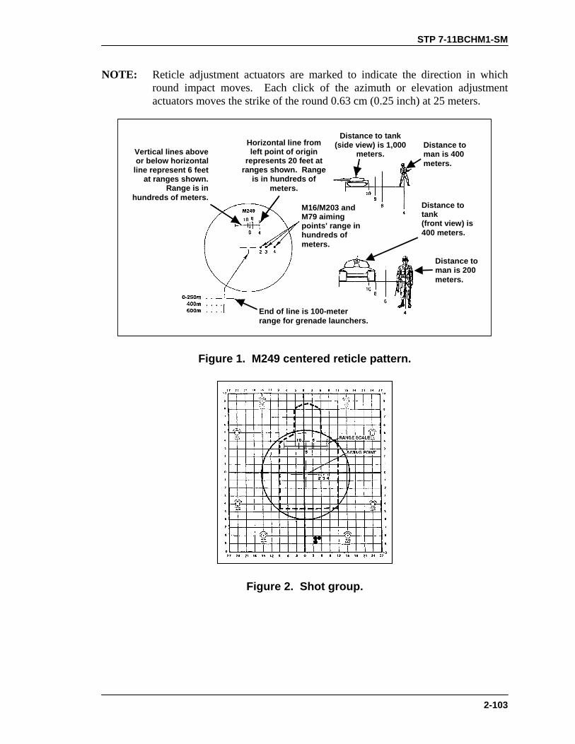
STP 7-11BCHM1-SM
2-103
NOTE: Reticle adjustment actuators are marked to indicate the direction in which round impact moves. Each click of the azimuth or elevation adjustment actuators moves the strike of the round 0.63 cm (0.25 inch) at 25 meters.
Horizontal line fromleft point of origin
represents 20 feet atranges shown. Range
is in hundreds ofmeters.
Distance to tank(side view) is 1,000
meters.Vertical lines aboveor below horizontal
line represent 6 feetat ranges shown.
Range is inhundreds of meters.
Distance toman is 400meters.
End of line is 100-meterrange for grenade launchers.
M16/M203 andM79 aimingpoints' range inhundreds ofmeters.
Distance toman is 200meters.
Distance totank(front view) is400 meters.
Figure 1. M249 centered reticle pattern.
Figure 2. Shot group.

STP 7-11BCHM1-SM
2-104
EVALUATION PREPARATION Setup: At the test site, provide the soldier with all the equipment given in the task conditions statement. Brief Soldier: Tell the soldier that he must zero a night vision sight AN/PVS-4 to an M249 machine gun.
EVALUATION GUIDE Performance Measures
Results
Zero the AN/PVS-4 to an M249 machine gun. P F
FEEDBACK If the soldier passes all steps, score him GO. If he fails any steps, score him NO-GO, then show him what he did wrong and how to do it correctly.
REFERENCES Required Related TM 11-5855-213-10 None FM 23-14
STP 7-11BCHM1-SM
2-105
ENGAGE TARGETS WITH AN M249 MACHINE GUN USING A NIGHT VISION SIGHT AN/PVS-4
071-010-0007
CONDITIONS During darkness, given an M249 machine gun equipped with a mounted night vision sight AN/PVS-4 that has been zeroed to the gun; linked 5.56-mm ammunition; engageable targets in the assigned sector of fire; and a requirement to engage the targets. STANDARDS Fire the M249 machine gun to effectively engage targets in the assigned sector of fire. Apply correct M249 machine gun target engagement techniques using night vision sight AN/PVS-4. Engage and hit each target.
TRAINING AND EVALUATION Training Information Outline
1. Place night vision sight AN/PVS-4 into operation (see task 071-315-0003, Operate a Night Vision Sight AN/PVS-4). 2. Assume a bipod-supported prone position or a bipod-supported fighting position. (These are the best positions for delivering effective M249 fire on targets when using the night vision sight AN/PVS-4.) 3. Detect and estimate range to the target. 4. Acquire a good sight picture. Adjust the weapon to place the correct aiming point (based on range to target) on the center base of the target. 5. Use the center point between the two horizontal lines in the middle of the reticle as the aiming point for ranges 0 to 300 meters. NOTE: Aiming points for ranges from 300 to 800 meters appear as small dots in a
vertical line down through the center of the reticle. a. Use Aiming Points 4 and 6 (400 and 600 meter) to fire at 400- and 600-meter targets, respectively. b. Use Aiming Point 8 (800 meter) to fire at 700-meter targets. c. Use Aiming Point 10 (1,000 meter) to fire at 800-meter targets.

STP 7-11BCHM1-SM
2-106
6. Fire the weapon in three-round bursts at the rate of fire appropriate for the size of the target. Use correct trigger manipulation techniques, that is, pull the trigger straight to the rear, then release it. 7. Apply correct engagement technique based on target types. a. Fixed fire. This is fire delivered against a point target, that is, against one aiming point, when the depth and width of the beaten zone covers the target completely. b. Traversing fire. This is fire distributed in width by successive changes in direction. This means moving the muzzle of the weapon to the left or right to distribute fire laterally. To make minor changes in direction, shift the shoulders to the right or left to locate successive aiming points throughout the width of the target area. For major changes, move the elbows, and align the body to remain directly behind the gun. c. Searching fire. This is fire distributed in width by successive changes in elevation. This means moving the muzzle of the weapon up or down to distribute fire in depth and choosing successive aiming points in depth throughout the target area. To make changes in elevation, move elbows closer together (this lowers the muzzle) or farther apart (this raises the muzzle). d. Traversing and searching fire. This is fire distributed in width and depth by successive changes in direction and elevation. Combining traversing and searching fire provides good target coverage. Make adjustments the same way you would for traversing or searching fire. This means moving the muzzle of the weapon to the left or right to distribute fire laterally. To make minor changes in direction, shift the shoulders to the right or left and choose successive aiming points throughout the width of the target area. For major changes, move the elbows and align the body to remain directly behind the gun. 8. Use observation of fire and adjustment of fire to place effective fire on the target. a. Observation of fire. Observe bursts of fire by noting the strike of the rounds in the target area or by observing tracers in flight. b. Adjustment of fire. Use the adjusted aiming point method to quickly adjust fires without adjusting the sight. If the initial burst misses the target, rapidly select a new aiming point the same distance from the center of impact of the initial burst, but in the opposite direction. Fire a second burst. 9. Apply fire correctly to engage specific targets. a. Point target. Engage point targets with fixed fire. b. Area target. Initially aim at the midpoint of the target area. Traverse and search to either flank, then back to the opposite flank. c. Linear target. Initially aim at the midpoint of the target. Traverse fire from one flank to the other to cover the entire target. d. Deep target. Initially aim at the midpoint of the target, unless another portion of the target is more critical or presents a greater threat. Search down to an aiming point in front of the near end, then back up to an aiming point beyond the far end. e. Linear target with depth. Initially aim at the midpoint of the target, unless another portion of the target is more critical or presents a greater threat. Traverse and search to the flank closest to your position, then back to the other flank to cover the entire target.

STP 7-11BCHM1-SM
2-107
f. Moving target. To hit a moving target; estimate the speed of the target and the lead required to hit it. Fire, then track the target as it moves. Adjust the lead by observing tracers and bullet strikes.
EVALUATION PREPARATION Setup: Evaluate this task on a live-fire range. Have the soldier fire Table III, Tasks 2 through 6 (FM 23-14, page 5-49). Evaluate the soldier’s ability to use correct engagement techniques to engage specific types of targets. Provide the soldier with equipment and materials required to fire Table III, tasks 2 through 6. Brief Soldier: Brief the soldier on range safety IAW installation SOP. Tell the soldier to assume the bipod-supported prone position or the bipod-supported fighting position. Tell him you are evaluating his ability to place effective fire on targets using the AN/PVS-4-equipped M249 machine gun.
EVALUATION GUIDE Performance Measures
Results
1. Place a night vision sight AN/PVS-4 into operation.
P F
2. Assume a correct bipod-supported prone position or bipod-supported fighting position.
P F
3. Detect and estimate the range to the target.
P F
4. Place effective fire on targets in three-round bursts at a rate of fire appropriate for the size of the target.
P F
5. Apply correct engagement techniques based on the types of targets.
P F
6. Apply fire correctly to engage specific targets. P F
FEEDBACK If the soldier passes all steps, score him GO. If he fails any steps, score him NO-GO, then show him what he did wrong and how to do it correctly.

STP 7-11BCHM1-SM
2-108
REFERENCES Required Related FM 23-14 None

STP 7-11BCHM1-SM
2-109
DISMOUNT A NIGHT VISION SIGHT AN/PVS-4 FROM AN M249 MACHINE GUN
071-010-0003 CONDITIONS Given an M249 machine gun with a mounted night vision sight AN/PVS-4, carrying case for night vision sight AN/PVS-4, and a requirement to remove the night vision sight AN/PVS-4 from the M249 machine gun. STANDARDS Remove the night vision sight AN/PVS-4 and mounting bracket assembly from the M249 machine without damage to equipment.
TRAINING AND EVALUATION Training Information Outline
1. Remove the sight from the mounting bracket assembly. a. Loosen the sight mounting screw by turning it counterclockwise until it is free of the sight. b. Remove the sight from the mounting bracket. 2. Remove the mounting bracket assembly. a. Loosen the mounting bracket screw until it is free of the feed cover mechanism. b. Lift the mounting bracket assembly from the M249. 3. Stow night vision sight AN/PVS-4 and mounting bracket assembly. a. Remove the batteries from the sight. b. Place the sight and bracket in the carrying case.
EVALUATION PREPARATION Setup: At the test site, provide the soldier with all the equipment given in the task conditions statement. Brief Soldier: Tell the soldier that he must remove and stow the night vision sight AN/PVS-4 and mounting bracket assembly without damage to equipment.
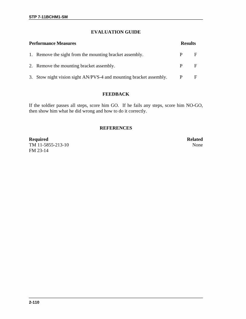
STP 7-11BCHM1-SM
2-110
EVALUATION GUIDE
Performance Measures
Results
1. Remove the sight from the mounting bracket assembly.
P F
2. Remove the mounting bracket assembly.
P F
3. Stow night vision sight AN/PVS-4 and mounting bracket assembly. P F
FEEDBACK If the soldier passes all steps, score him GO. If he fails any steps, score him NO-GO, then show him what he did wrong and how to do it correctly.
REFERENCES Required Related TM 11-5855-213-10 None FM 23-14

STP 7-11BCHM1-SM
2-111
M60 MACHINE GUN
CONSTRUCT A FIGHTING POSITION FOR AN M60 MACHINE GUN
071-312-3004 CONDITIONS Given load-bearing equipment (LBE) with bayonet, scabbard, entrenching tool, poncho, individual weapon, M60 machine gun with all components, the specific location and sectors of fire for the position to be constructed, and logs to construct overhead cover. NOTE: The position should incorporate natural cover such as mounds of earth,
stumps, trees, or rocks. The position must have observation and general fields of fire. Selective clearing begins after the crew digs the position.
STANDARDS Ensure position provides frontal and rear protection and overhead cover for the gun crew, and that it allows coverage of primary and secondary sectors of fire.
TRAINING AND EVALUATION Training Information Guide
Cover The position is protected by a natural or man-made parapet. The
parapet should be thick enough to protect from direct small-arms fire and high enough to hide the helmets of soldiers in the position. Also, the position should be protected from indirect fire (shrapnel) by at least 12 inches of dirt and log overhead.
Concealment The position is not easily detected from the front. It blends with surroundings so an approaching soldier, about 35 meters to the front (hand-grenade range), cannot detect it. Aerial protection prevents observation from the air.
Fields of fire The position provides good observation and fields of fire in both sectors, without destroying natural camouflage.
Size and shape The position is armpit deep and wide enough to allow two soldiers with LBE to move freely. The position must have two distinct firing platforms whenever possible (Figure 1).
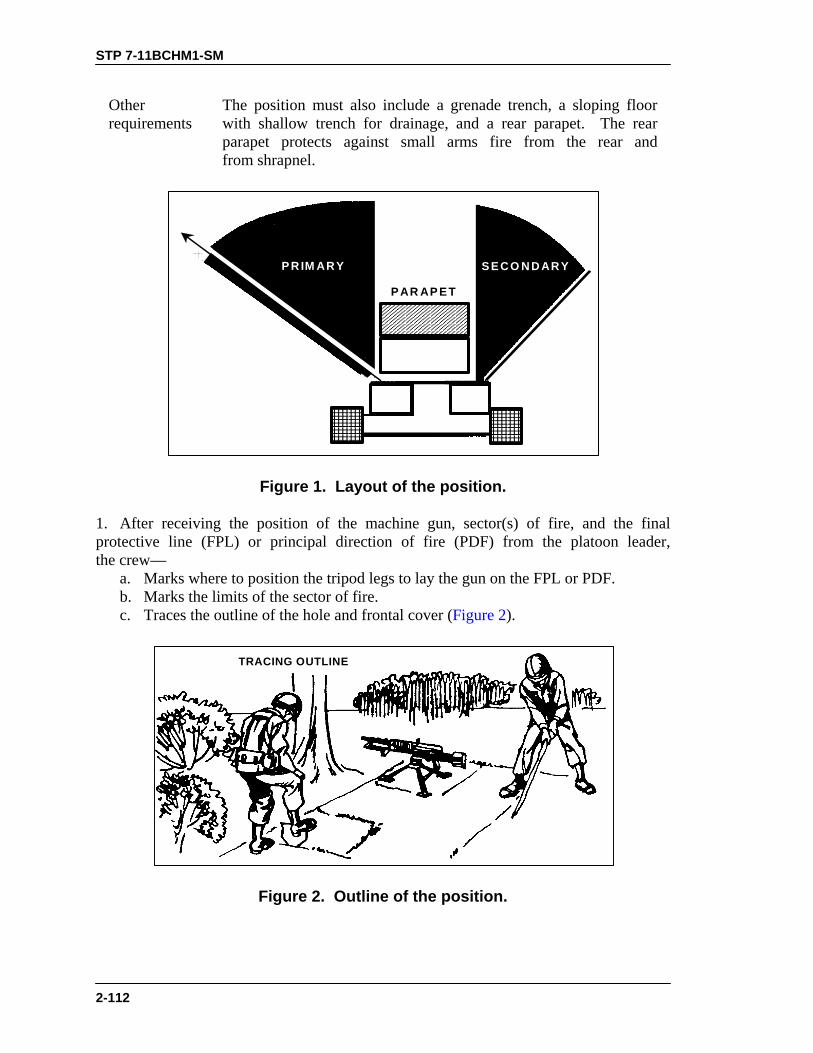
STP 7-11BCHM1-SM
2-112
Other requirements
The position must also include a grenade trench, a sloping floor with shallow trench for drainage, and a rear parapet. The rear parapet protects against small arms fire from the rear and from shrapnel.
S E C O N D AR YP R IM AR Y
P AR AP E T
Figure 1. Layout of the position.
1. After receiving the position of the machine gun, sector(s) of fire, and the final protective line (FPL) or principal direction of fire (PDF) from the platoon leader, the crew— a. Marks where to position the tripod legs to lay the gun on the FPL or PDF. b. Marks the limits of the sector of fire. c. Traces the outline of the hole and frontal cover (Figure 2).
TRACING OUTLINE
Figure 2. Outline of the position.

STP 7-11BCHM1-SM
2-113
2. The crew digs firing platforms first. After digging the platforms 4 to 6 inches deep, they position the machine gun on one of the platforms, ensuring it covers the primary sector of fire. Then they complete the remaining part of the position around the firing platforms (Figure 3). Placing the machine gun on the firing platform at this time— a. Lessens exposure in the event the crew must fire before completing the position. b. Reduces the height of the frontal cover needed. 3. The crew digs the hole, places some of the dirt where they need frontal cover, and uses the rest for flank and rear cover. They dig the hole deep enough to protect themselves, but at a depth that still allows the gunner to fire comfortably—about armpit deep.
FIRINGPLATFORM
FIRINGPLATFORM
DIGGING POSITION
Figure 3. Preparation of the position and firing platforms.
4. The crew digs three trench-shaped grenade sumps at various points so any of them can kick a grenade into one (Figure 4).

STP 7-11BCHM1-SM
2-114
TOP VIEW
FIRINGPLATFORM
FIRINGPLATFORM
GRENADE SUMP
Figure 4. Location of grenade sumps.
5. When a position has no secondary sector of fire, the crew digs only half of the position (Figure 5).
Figure 5. Single-sector position.
6. The crew builds overhead cover for a machine gun position the same as for a two-man fighting position (Figure 6)
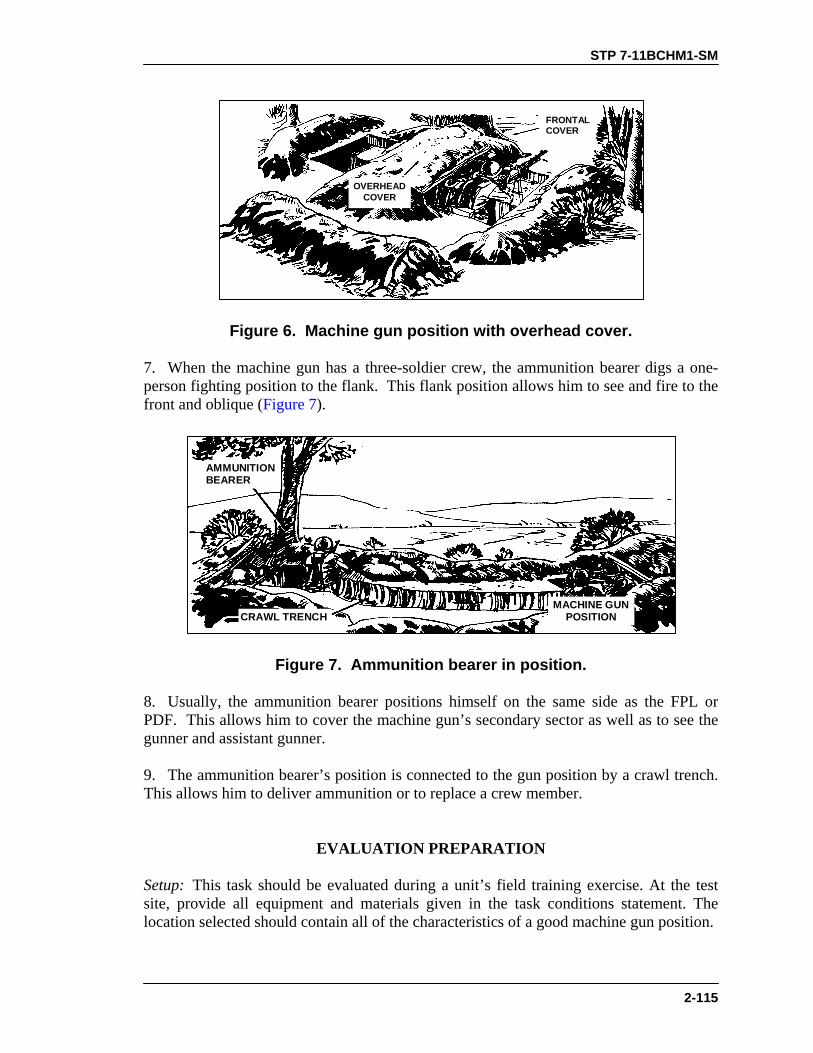
STP 7-11BCHM1-SM
2-115
OVERHEADCOVER
FRONTALCOVER
Figure 6. Machine gun position with overhead cover.
7. When the machine gun has a three-soldier crew, the ammunition bearer digs a one-person fighting position to the flank. This flank position allows him to see and fire to the front and oblique (Figure 7).
CRAWL TRENCH
AMMUNITIONBEARER
MACHINE GUNPOSITION
Figure 7. Ammunition bearer in position.
8. Usually, the ammunition bearer positions himself on the same side as the FPL or PDF. This allows him to cover the machine gun’s secondary sector as well as to see the gunner and assistant gunner. 9. The ammunition bearer’s position is connected to the gun position by a crawl trench. This allows him to deliver ammunition or to replace a crew member.
EVALUATION PREPARATION Setup: This task should be evaluated during a unit’s field training exercise. At the test site, provide all equipment and materials given in the task conditions statement. The location selected should contain all of the characteristics of a good machine gun position.

STP 7-11BCHM1-SM
2-116
NOTES: 1. The position’s degree of completion depends on the time available. 2. During training, comply with unit SOP and any local regulations
concerning the cutting of live vegetation, digging holes, and preventing erosion.
Brief Soldier: Tell the soldier to position the machine gun to cover the FPL or the PDF, to outline the position on the ground, and to construct the position to meet all requirements.
EVALUATION GUIDE Performance Measures
Results
1. Position the machine gun to lay on the FPL or PDF.
P F
2. Ensure that the secondary sector can also be covered.
P F
3. Outline the position on the ground.
P F
4. Dig the firing platform first.
P F
5. Position the machine gun on the firing platform to cover the FPLor PDF.
P F
6. Construct frontal, flank, and rear cover.
P F
7. Complete construction of the position to the extent required. P F
FEEDBACK If the soldier passes all steps, score him GO. If he fails any steps, score him NO-GO, then show him what he did wrong and how to do it correctly.
REFERENCES Required Related None FM 7-7 FM 7-8

STP 7-11BCHM1-SM
2-117
ZERO AN M60 MACHINE GUN 071-312-3030
CONDITIONS Given an M60 machine gun on a live fire range or on terrain where you are permitted to fire the M60, a 300-meter target, and a 30-round belt of linked 7.62 ammunition. STANDARDS Using no more than 30 rounds, adjust the sights on the M60 machine gun so that a correct sight picture causes a fired round to impact the target at the point of aim.
TRAINING AND EVALUATION Training Information Outline
1. Set the sights for initial firing. a. Elevation. Index the known range (300 meters) to the target on the elevation scale. b. Windage. Align the windage index on zero windage. 2. Assume a good stable firing position (Figure 1 and Figure 2).
Figure 1. Prone position (bipod).

STP 7-11BCHM1-SM
2-118
Figure 2. Prone position (tripod).
3. Fire a six- to nine-round burst at the center base of the target. Note where the burst strikes in relation to the target. 4. Adjust the sights if needed, so that rounds impact on the target. a. Adjust sights for deflection. Determine if the center of the beaten zone is left or right of the target. Correct by moving the windage knob the necessary number of clicks in the direction of the target. One click or 1 mil on the windage knob moves the line of aim 1 meter at 1,000 meters (Figure 3).
RANGE(METERS
ONE CLICK OF WINDAGE KNOBMOVES LINE OF AIM
1,000 1.0 METER700 0.7 METER600 0.6 METER500 0.5 METER400 0.4 METER300 0.3 METER
Figure 3. Windage chart.
EXAMPLE: If the target is at 500 meters, and the center of the beaten zone is 1 meter left of the target, then move the windage knob 2 clicks to the right.
b. Adjust the sights for elevation. Determine if the center of the beaten zone is above (high) or below (low) the point of aim. Make elevation changes accordingly. Because determining this relationship is difficult, you must rely on trial and error until you learn to make reliable estimates. 5. Fire a confirming burst. If the round does not hit the target, repeat Steps 3 and 4 until it does.
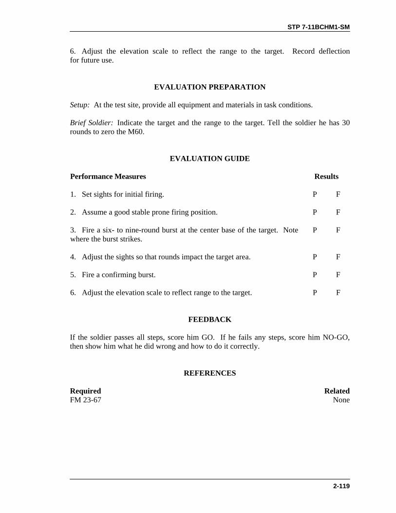
STP 7-11BCHM1-SM
2-119
6. Adjust the elevation scale to reflect the range to the target. Record deflection for future use.
EVALUATION PREPARATION
Setup: At the test site, provide all equipment and materials in task conditions. Brief Soldier: Indicate the target and the range to the target. Tell the soldier he has 30 rounds to zero the M60.
EVALUATION GUIDE Performance Measures
Results
1. Set sights for initial firing.
P F
2. Assume a good stable prone firing position.
P F
3. Fire a six- to nine-round burst at the center base of the target. Note where the burst strikes.
P F
4. Adjust the sights so that rounds impact the target area.
P F
5. Fire a confirming burst.
P F
6. Adjust the elevation scale to reflect range to the target. P F
FEEDBACK If the soldier passes all steps, score him GO. If he fails any steps, score him NO-GO, then show him what he did wrong and how to do it correctly.
REFERENCES Required Related FM 23-67 None

STP 7-11BCHM1-SM
2-120
ZERO A NIGHT VISION SIGHT AN/PVS-4 TO AN M60 MACHINE GUN
071-315-2313 CONDITIONS Given a target at a distance of 25 meters, a zeroed M60 machine gun with a mounted AN/PVS-4, 20 rounds of ammunition, and a device to measure 11.9 centimeters or 4 5/8 inches. STANDARDS Adjust the AN/PVS-4 controls: align the sight reticle zero range aiming point on the target aiming point so that the shot group is 11.9 centimeters or 8.5 squares below the target aiming point.
TRAINING AND EVALUATION Training Information Outline
WARNINGTo prevent eye injury from weapon recoil, attach the eyeguard to the sight before firing the weapon.
CAUTIONThe sight may be zeroed in daylight or darkness. However, ifzeroing during bright daylight, use the daylight cover to avoiddamaging the image-intensifier assembly.
1. Turn on the sight. 2. Place the zeroing range aiming point of the reticle on the target aiming point by adjusting the azimuth and elevation actuators (Figure 1).

STP 7-11BCHM1-SM
2-121
RETICLEAIMINGPOINT
Figure 1. Reticle aiming point.
3. Fire three rounds to seat the sight on the gun. Retighten the mounting knob. 4. Fire three rounds (single shot) to obtain a good shot group. 5. Locate the center of the shot group. 6. From the center of the shot group, adjust as needed to move the shot group to the point 11.9 centimeters, or 4 5/8 inches, directly below the target aiming point. On the target sheet, this point is slightly outside the target area, as shown in Figure 2. On the 25-meter zeroing target for the M16A2 rifle, each square measures 0.9 centimeter. (The squares on the 25-meter zeroing target for the M16A1 rifle measure 0.7 centimeter each). Figure 3 shows the location of the controls.
EXAMPLE: To adjust the shot group in Figure 2 to the desired point of impact (shown)—
WINDAGEDetermine the correction for windage.
Count how many squares the center of the shot group is from the vertical “0” lines(3.3 squares away, in this example).
(number of squares x 0.9)
0.63= number of windage clicks
• Multiply this by the width of each square (0.9 centimeter). This gives the result 2.97.• Divide this by 0.63 (the distance one click of windage on the AN/PVS-4 moves
the strike of the round).• The final answer is the number of windage clicks needed to center the shot group:
3.3 x 0.9 2.97
0.63=
0.63= 4.7 clicks (round to 5)
Move the azimuth adjustment actuator 5 clicks counterclockwise to adjust for windage.
(Example continues on next page)

STP 7-11BCHM1-SM
2-122
(Continued from Previous Page)
ELEVATIONDetermine the correction for elevation. In this example, the desired point of impact is2.9 centimeters outside the target area, so add 2.9 to the measurement of the squares:
(number of squares x 0.9) + 2.9
0.63= number of windage clicks
(6.8 x 0.9) + 2.9 6.12 + 2.9 9.02
0.63=
0.63=
0.63= 14.31 clicks (round to 14)
Move the elevation adjustment actuator 14 clicks counterclockwise to adjust for elevation.
NOTE: Each click of the azimuth or elevation adjustment actuator moves the strikeof the round 0.63 centimeter, or 1/4 inch, at a range of 25 meters.
POINTOF IMPACTFOR ZEROEDSHOT GROUP
ZERO TARGET DATA
1. Rotate rear sight elevationknob to the 8/3 setting, thenup (right) one click past the300 mark, for zeroing at 25meters.
2. Aim at target center. Adjustsights to move shot groupcenter as close as possible tothe white dot in the centerof the target.
REAR SIGHT
FRONTSIGHT
POINTOF AIM
300 METERS
Figure 2. Aiming point and point of impact.
7. Once you have adjusted for windage and elevation— a. Realign the reticle aiming point to the target aiming point by moving the complete weapon system. b. DO NOT realign the aiming points by adjusting the azimuth and elevation actuators. 8. Repeat the process until the center of the shot group is at the point 11.9 centimeters, or 4 5/8 inches, below the target aiming point.
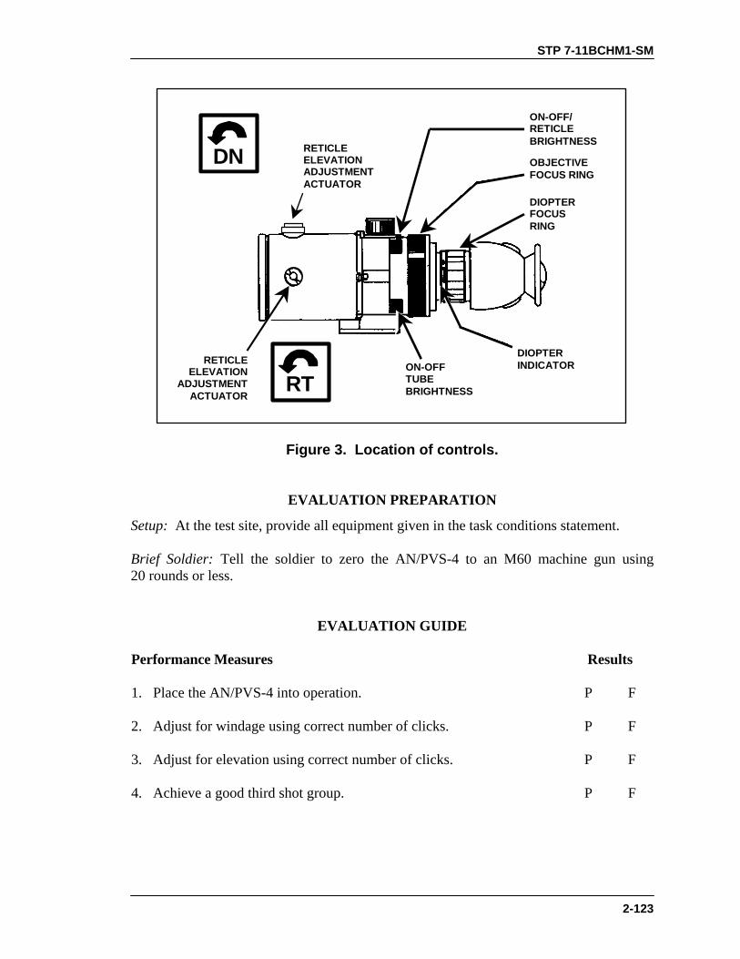
STP 7-11BCHM1-SM
2-123
DN
RT
ON-OFF/RETICLEBRIGHTNESS
OBJECTIVEFOCUS RING
DIOPTERFOCUSRING
ON-OFFTUBEBRIGHTNESS
DIOPTERINDICATORRETICLE
ELEVATIONADJUSTMENT
ACTUATOR
RETICLEELEVATIONADJUSTMENTACTUATOR
Figure 3. Location of controls.
EVALUATION PREPARATION
Setup: At the test site, provide all equipment given in the task conditions statement. Brief Soldier: Tell the soldier to zero the AN/PVS-4 to an M60 machine gun using 20 rounds or less.
EVALUATION GUIDE Performance Measures
Results
1. Place the AN/PVS-4 into operation.
P F
2. Adjust for windage using correct number of clicks.
P F
3. Adjust for elevation using correct number of clicks.
P F
4. Achieve a good third shot group. P F

STP 7-11BCHM1-SM
2-124
FEEDBACK If the soldier passes all steps, score him GO. If he fails any steps, score him NO-GO, then show him what he did wrong and how to do it correctly.
REFERENCES Required Related None TM 11-5855-213-10

STP 7-11BCHM1-SM
2-125
ENGAGE TARGETS WITH AN M60 MACHINE GUN USING A NIGHT VISION SIGHT AN/PVS-4
071-315-0008 CONDITIONS At night, given a zeroed M60 machine gun with a mounted and zeroed AN/PVS-4, targets between 100 and 350 meters, and a belt of ammunition. STANDARDS Acquire, engage, and suppress each target in sector and suppress, destroy, or kill each one.
TRAINING AND EVALUATION Training Information Outline
NOTE: Ensure the AN/PVS-4 is equipped with the proper sight reticle (Figure 1). 1. Place the sight into operation (see Task 071-315-0003, Place an AN/PVS-4 into Operation). 2. Use the sight reticle. The AN/PVS-4 sight reticle consists of two parts when it is used with the M60 machine gun (Figure 1).
AIMINGPOINTS
RANGESCALEM14 – M60
Figure 1. Sight reticle.
a. The upper part of the reticle (range scale) is used to determine range to the target. b. The lower part of the reticle is used for aiming the weapon.

STP 7-11BCHM1-SM
2-126
3. Determine range to target. a. The vertical lines on the range scale tell how far away a 6-foot man is. (1) Place the target on the horizontal line and match it with one of the vertical lines (A, Figure 2). (2) Read the number at the bottom or top of the vertical line. That is the distance in hundreds of meters to the target. (3) If the figure is the same height as the vertical line above and below the horizontal line, the distance is half the number at the top or bottom of that line (B, Figure 2). In A, Figure 2, the man above the horizontal line is 400 meters away; the man in B, Figure 2, is 200 meters away. b. The horizontal line of the range scale indicates the range (in hundreds of meters) of a 20-foot target such as a tank or large truck viewed from the side. (1) Place the left edge of the vehicle at the left side of the horizontal line (Figure 3). (2) The range to the tank is read from the scale at the right edge of the tank. As shown in A, Figure 3, the range to the vehicle is 1,000 meters. (3) When viewed from the front or rear, the vehicle’s width is about half its length. Placement of the vehicle width on the range scale is read as half the range scale value. As shown in B, Figure 3, the range to the vehicle is 400 meters.
A B
Figure 2. Range determination using vertical lines.
A B
Figure 3. Range determination using horizontal lines.
4. Engage targets using the sight reticle.

STP 7-11BCHM1-SM
2-127
WARNINGTo prevent eye injury from weapon recoil, attach the eyeguard to the sight before firing the weapon.
a. The M60 aiming point for ranges out to 250 meters is the center of the two horizontal lines (zero aiming point) (Figure 4). The numbered dots below the horizontal lines are the aiming points for each even-numbered hundred meters. The odd-numbered hundred meter aiming points are between the dots. b. Locate the target, estimate the range, and place the proper aiming point on the target. c. Fire the weapon using correct marksmanship procedure.
AIMING POINT70 METERS
AIMING POINT400 METERS
AIMING POINT0 to 250 METERS
Figure 4. Zero aiming point.
EVALUATION PREPARATION
Setup: At a live-fire range, provide the equipment and material shown in the task conditions statement. Brief Soldier: Tell the soldier to engage all targets and hit each one at least once.
EVALUATION GUIDE Performance Measures
Results
1. Place the AN/PVS-4 into operation.
P F

STP 7-11BCHM1-SM
2-128
EVALUATION GUIDE Performance Measures
Results
2. Engage targets. a. Engage a 100- to 350-meter target with at least one hit. b. Engage a 250-meter target with at least one hit. c. Engage a 250- to 300-meter target with at least one hit.
P F
3. Take the AN/PVS-4 out of operation. P F
FEEDBACK If the soldier passes all steps, score him GO. If he fails any steps, score him NO-GO, then show him what he did wrong and how to do it correctly.
REFERENCES Required Related None FM 23-67 TM 11-5855-213-10

STP 7-11BCHM1-SM
2-129
CALIBER .50 MACHINE GUN
MAINTAIN A CALIBER .50 M2 MACHINE GUN 071-022-0001
CONDITIONS Given a caliber .50 M2 HB machine gun, M3 tripod, MK64 gun cradle mount, pintle, traversing and elevating (T&E) mechanism, linked caliber .50 ammunition, headspace and timing gauge, cleaner lubricant and preservative (CLP), rifle bore cleaner (RBC), lubricating oil arctic weather (LAW), lubricating oil general purpose (PL-M), lubricating oil semi-fluid (LSA), carbon removing compound, the bore brush, wiping rags, M4 cleaning rod, small arms (2-inch) cleaning swabs, and a wooden block. STANDARDS Clean and lubricate the caliber .50 M2 HB machine gun and its components. Clean and inspect all parts and ammunition and turn in for maintenance those found to be unserviceable. Assemble the gun so that it is operational.
TRAINING AND EVALUATION Training Information Outline
1. Clear the caliber .50 machine gun. a. Unlock the bolt latch release and raise the cover (Figure 1). b. Pull and lock the bolt to the rear, leaving the retracting slide handle to the rear. c. Inspect the chamber and T-slot to make sure they hold no rounds. d. Place a wooden block inside the receiver, between the bolt and the rear of the barrel.
COVER GROUP
BOLT LATCH
RETRACTINGSLIDE
HANDLE
Figure 1. Raising the cover.

STP 7-11BCHM1-SM
2-130
e. Insert the cleaning rod in the muzzle end of the barrel until you can see the rod in the receiver. Remove the cleaning rod. f. Grasp the retracting slide handle, press the bolt latch release, and ease the bolt forward. Close the cover. 2. Disassemble the machine gun. a. Remove the barrel assembly. (1) Raise the cover group (Figure 1). (2) Grasp the retracting slide handle with the right hand, palm up. Pull the bolt to the rear until the barrel locking spring lug aligns with the 3/8-inch hole in the right side plate of the receiver (Figure 2). (3) Place the smallest loop of a caliber .50 link between the trunnion block and the barrel extension (Figure 2). This keeps the barrel locking spring lug aligned with the 3/8-inch hole. (4) Unscrew the barrel from the receiver. Be careful not to damage the threads or barrel locking notches. (5) Remove caliber .50 link to allow the bolt to go forward slowly. Make sure the bolt group does not slam forward with the barrel removed.
PALMUP
EXTRACTOR
SMALLEST LOOP OFCAL .50 LINK
RIGHTSIDEPLATE
BARREL LOCKING SPRING LUGALIGNED WITH 3/8-INCH HOLE
Figure 2. Alignment of the lug.
b. Remove the backplate assembly.
WARNINGDo not remove the backplate unless the bolt is in theforward position. When removing the backplate, stand toone side of the weapon to avoid possible injury from thedriving spring rod.
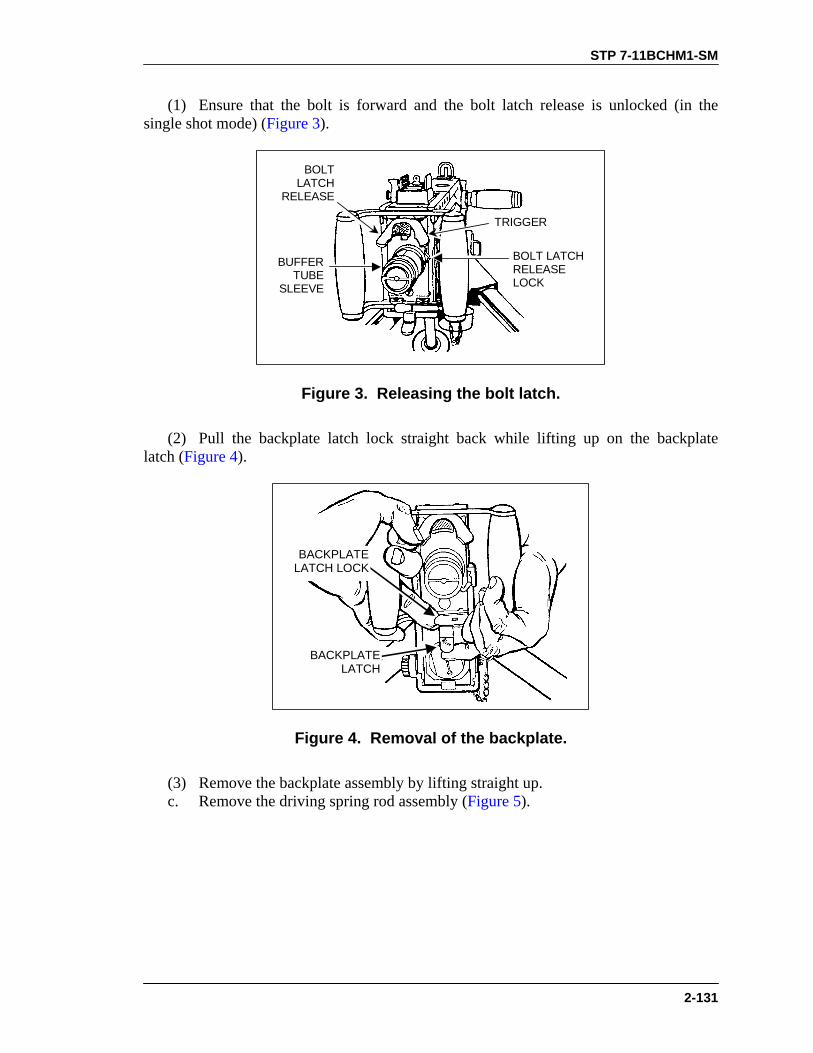
STP 7-11BCHM1-SM
2-131
(1) Ensure that the bolt is forward and the bolt latch release is unlocked (in the single shot mode) (Figure 3).
BUFFERTUBE
SLEEVE
BOLT LATCHRELEASELOCK
TRIGGER
BOLTLATCH
RELEASE
Figure 3. Releasing the bolt latch.
(2) Pull the backplate latch lock straight back while lifting up on the backplate latch (Figure 4).
BACKPLATELATCH LOCK
BACKPLATELATCH
Figure 4. Removal of the backplate.
(3) Remove the backplate assembly by lifting straight up. c. Remove the driving spring rod assembly (Figure 5).

STP 7-11BCHM1-SM
2-132
DRIVINGSPRING RODASSEMBLY
BOLTLATCH
Figure 5. Removal of the driving spring rod assembly.
(1) Push the rear of the driving rod assembly forward and to the left to free it from the side of the receiver.
WARNINGNever try to charge the machine gun while the backplate isoff and the driving spring rod assembly is in place. If thebackplate is off and the driving spring assembly iscompressed, the retaining pin on the driving spring can slipfrom its seat in the side plate. This could cause seriousinjury to anyone behind the machine gun.
(2) Pull the driving spring rod assembly to the rear and out of the receiver. d. Remove the bolt assembly. (1) Retract the bolt assembly far enough to the rear to align the bolt stud with the bolt stud hole in the right side plate of the receiver (Figure 6).

STP 7-11BCHM1-SM
2-133
BOLT STUD HOLE
BOLT STUD
SHOULDER
Figure 6. Removal of the bolt stud.
(2) If you accidentally move the bolt all the way to the rear, the bolt latch will engage in the bolt latch notches in the top of the bolt. If this occurs, raise the bolt latch and push the bolt forward to align the bolt stud with the clearance hole (Figure 7).
BOLTLATCH
BOLT
TRIGGERLEVER
BOLTSTUD
Figure 7. Unlatching the bolt.
(3) Remove the bolt stud. (4) Remove the bolt assembly by pulling it from the rear of the receiver (Figure 8).

STP 7-11BCHM1-SM
2-134
BOLTLATCH
BOLT
Figure 8. Removal of the bolt from the receiver.
(5) Disassemble the bolt. (a) Rotate the cartridge extractor upward and remove it from the left side of the bolt (Figure 9).
LEFT SIDEOF BOLT
CARTRIDGE EXTRACTOR BOLTSWITCH
Figure 9. Removal of the cartridge extractor and bolt.
(b) Remove the bolt switch by lifting it straight up. (c) Place the cocking lever in its rearmost position. Press down on the sear with a swab holder and release the firing pin spring (Figure 10).

STP 7-11BCHM1-SM
2-135
SEAR
COCKING LEVER
SWABHOLDER
SECTION
Figure 10. Releasing the firing pin spring.
(d) Insert a swab holder section in the hole at the rear of the bolt and push out the cocking lever pin and the cocking lever (Figure 11).
COCKINGLEVER PIN
COCKINGLEVER
COCKINGLEVER PIN
SWABHOLDERSECTION
Figure 11. Removal of the cocking lever pin and cocking lever.
(e) Use the thin end of cocking lever to rotate the accelerator stop lock to the center of the bolt, then pry up the accelerator stop lock and remove it (Figure 12).
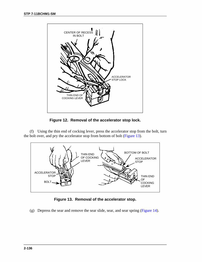
STP 7-11BCHM1-SM
2-136
CENTER OF RECESSIN BOLT
THIN END OFCOCKING LEVER
ACCELERATORSTOP LOCK
Figure 12. Removal of the accelerator stop lock.
(f) Using the thin end of cocking lever, press the accelerator stop from the bolt, turn the bolt over, and pry the accelerator stop from bottom of bolt (Figure 13).
ACCELERATORSTOP
BOTTOM OF BOLT
BOLT
ACCELERATORSTOP THIN END
OFCOCKINGLEVER
THIN ENDOF COCKINGLEVER
Figure 13. Removal of the accelerator stop.
(g) Depress the sear and remove the sear slide, sear, and sear spring (Figure 14).

STP 7-11BCHM1-SM
2-137
SEARSLIDE
SEARSPRING
SEAR
Figure 14. Removal of the sear slide, sear, and sear spring.
(h) Tip the front end of the bolt upward and remove the firing pin extension assembly (Figure 15). (i) Remove firing pin from firing pin extension assembly.
FRONT ENDOF BOLT
FIRING PINEXTENSIONASSEMBLY
Figure 15. Removal of the firing pin extension assembly.
e. Remove the barrel buffer and barrel extension assemblies (Figure 16).

STP 7-11BCHM1-SM
2-138
Figure 16. Removal of the barrel buffer group and barrel extension group.
(1) Insert a pointed instrument (you can use the pointed end of the M4 the cleaning rod) in the hole at the lower rear corner of the right side plate. Depress the buffer body lock and, at the same time, place one hand inside the receiver and push the barrel extension and buffer assemblies to the rear until the buffer accelerator is near the rear of the receiver body.
WARNINGMaintain thumb pressure on the buffer accelerator whileremoving the barrel buffer and barrel extension assemblies.
(2) Maintain pressure on the buffer accelerator with your thumb and remove the barrel buffer and barrel extension assemblies from the receiver. Separate them by pushing forward on the accelerator tips (Figure 17).
ACCELERATOR TIPS
BARREL BUFFERBODY GROUP
BARRELEXTENSIONGROUP
Figure 17. Separation of the barrel buffer and barrel extension assemblies.
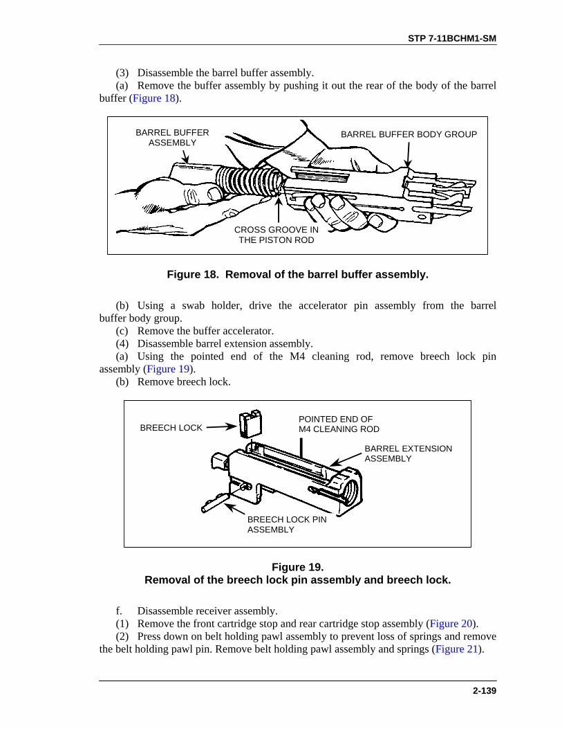
STP 7-11BCHM1-SM
2-139
(3) Disassemble the barrel buffer assembly. (a) Remove the buffer assembly by pushing it out the rear of the body of the barrel buffer (Figure 18).
CROSS GROOVE INTHE PISTON ROD
BARREL BUFFERASSEMBLY
BARREL BUFFER BODY GROUP
Figure 18. Removal of the barrel buffer assembly.
(b) Using a swab holder, drive the accelerator pin assembly from the barrel buffer body group. (c) Remove the buffer accelerator. (4) Disassemble barrel extension assembly. (a) Using the pointed end of the M4 cleaning rod, remove breech lock pin assembly (Figure 19). (b) Remove breech lock.
POINTED END OFM4 CLEANING ROD
BARREL EXTENSIONASSEMBLY
BREECH LOCK
BREECH LOCK PINASSEMBLY
Figure 19. Removal of the breech lock pin assembly and breech lock.
f. Disassemble receiver assembly. (1) Remove the front cartridge stop and rear cartridge stop assembly (Figure 20). (2) Press down on belt holding pawl assembly to prevent loss of springs and remove the belt holding pawl pin. Remove belt holding pawl assembly and springs (Figure 21).

STP 7-11BCHM1-SM
2-140
(3) Raise the loop of the trigger lever pin and rotate it into a vertical position. Reach inside the receiver, grasp the trigger lever, and remove the trigger pin assembly and trigger lever (Figure 22).
FRONT CARTRIDGESTOP
REAR CARTRIDGESTOP ASSEMBLY
RECEIVER
BELT-HOLDINGPAWL PIN
Figure 20. Removal of the cartridge stop assemblies.
TWOSPRINGS
LOOP OFTRIGGER
LEVER PIN
TWOSPRINGS
BELT-HOLDINGPAWL PIN
Figure 21. Removal of the belt holding pawl pin, assembly,
and springs.

STP 7-11BCHM1-SM
2-141
TRIGGER LEVER
RECEIVER
TRIGGER LEVERPIN ASSEMBLY
Figure 22. Removal of the trigger lever pin assembly and trigger lever.
3. Clean the .50 caliber machine gun and components. a. Barrel assembly. (1) Clean the bore. Screw the bore brush into the cleaning rod, dip the bore brush in RBC, and push the cleaning rod through the chamber end of barrel. Unscrew the bore brush from the cleaning rod, remove the cleaning rod from the bore, and screw the bore brush into the cleaning rod. Repeat process until clean. (2) Clean the chamber. Screw the chamber brush into the cleaning rod, dip the chamber brush in RBC, and clean the chamber using a clockwise twisting motion. (3) Insert a cleaning swab in the cleaning rod and swab out the bore from the chamber end and back. Repeat until a swab comes out clean. (4) Wipe outside surfaces of barrel with carbon removing compound. (5) Remove all traces of RBC before lubricating. NOTE: Do not submerge the backplate assembly in any fluid. b. Backplate assembly. Use only clean wiping rags to remove foreign matter from backplate. c. Bolt assembly. Clean all parts of bolt assembly with a cleaning swab saturated with carbon removing compound. Clean face of the bolt with a cleaning swab soaked in RBC. d. Clean barrel buffer assembly, barrel extension assembly, and receiver assembly with a cleaning swab saturated with carbon removing compound. Wipe all parts dry with clean wiping rags. e. Clean components. (1) T&E mechanism. Remove foreign matter with a clean dry wiping rag. Use a small arms cleaning brush to clean numbers on the scale. (2) Clean M3 tripod, MK64 gun cradle mount, and pintle with a cleaning swab saturated with carbon removing compound. Wipe all parts dry with clean wiping rags.

STP 7-11BCHM1-SM
2-142
f. Ammunition. Remove foreign matter with a clean dry wiping rag. 4. Inspect for serviceability. a. Barrel assembly. (1) Check barrel locking notches for wear. (2) Check barrel for rust. (3) Check the bore for bulges, missing bands, and large pits. b. Backplate assembly. (1) Check guides for burrs and bends. (2) Check backplate latch and backplate lock for proper functioning. (3) Make sure locking pins are in place. (4) Check trigger and bolt latch release for proper functioning. (5) Make sure handle grips do not move freely and are not cracked. c. Driving rod assembly. (1) Check for flat spots on springs. (2) Make sure springs operate freely and rod and pin are not bent. d. Bolt assembly. (1) Check movement of cartridge extractor in bolt: it should raise and lower without binding. Check movement of cartridge ejector. (2) Check bolt switch, cocking lever pin, cocking lever, accelerator stop lock, accelerator stop, and sear slide for cracks, bends, and burrs. (3) Inspect sear for cracks and burrs. Inspect sear notch for wear, chips, and burrs. Inspect sear spring for breaks and lack of tension. (4) Inspect firing pin for cracks and chipped or sharp tip. Tip should be smooth and well rounded. (5) Check firing pin extension for cracks, burrs, and free movement in bolt. (6) Make sure bolt is free of burrs and cracks and firing pin hole is not visually out of round. e. Barrel buffer assembly. (1) Inspect buffer body lock for tension, staking, and retention in barrel buffer body. (2) Inspect buffer accelerator for broken claws or chipped tips. (3) Inspect accelerator pin assembly for broken or missing spring. (4) Inspect buffer spring for cracks or breaks. (5) Inspect breech lock depressors. They must have slight vertical (up and down) movement but should have no lateral (side to side) f. Barrel extension assembly. (1) Make sure barrel extension assembly is not bent and that the bolt guideways are smooth and free of burrs. (2) Inspect threads of barrel extension assembly for damage. (3) Make sure barrel locking spring is staked and fully seated in its groove. Also, make sure the locking end of the spring has good tension and the lug is not damaged. (4) Check breechblock for smooth movement in guideways of barrel extension assembly. g. Receiver and cover assembly. (1) Inspect belt holding pawl brackets for looseness, bends, and cracks. (2) Inspect side plates for bends that would affect movement of any internal parts.

STP 7-11BCHM1-SM
2-143
(3) Check for cracked and burrs at backplate grooves. (4) Check operation of rear sight. Make sure windage and elevation screws function properly, leaf assembly has good spring tension, and sight assembly is secured tightly to receiver. (5) Make sure bolt stop is present and in good condition. (6) Make sure trigger lever moves freely. (7) Make sure trigger lever pin locks in place. (8) Make sure cotter pin is in place on extractor switch. (9) Check retracting slide assembly for visible damage. Check retracting slide handles for smooth movement. Make sure cotter pins are present and in good condition and safety wire is in place and properly laced. h. Inspect components. (1) T&E mechanism. (a) Inspect hand wheels and threads for burrs and rust. Check hand wheels for smooth operation. (b) Make sure traversing slide lock lever has spring action. Make sure elevating mechanism sleeve fits on traversing bar and clamps firmly. (c) Check traversing and elevating scales for legibility. (d) Inspect quick release pin and chain for burrs and rust. Check quick release pin for presence of spring loaded balls. (2) M3 tripod. (a) Check for completeness of tripod. Make sure all nuts and bolts are tightly secured. (b) Check for visible cracks on legs and tripod head. (c) Check for missing, broken, or inoperative sleeve lock latch. (d) Check pintle lock assembly. Check surfaces of pintle, bolt, and nut for burrs and rust. Make sure cotter pin is present and in good condition. (e) Check locking action of front leg clamping assembly. (f) Check that rear legs lock in the open position. Make sure sleeve latch notch and right leg slide notch engage completely. Make sure latch spring has good tension. (g) Check telescoping, indexing, and locking action of rear legs and front leg clamping assembly. (3) MK64 gun cradle mount. (a) Check for missing or damaged parts. (b) Check for rust, cracks, and burrs. (c) Check pintle lock assembly. Check surfaces of pintle, bolt, and nut for burrs and rust. Make sure cotter pin is present and in good condition. i. Inspect ammunition. Check for damage or corroded rounds. 5. Lubricate the .50 caliber machine gun. a. Remove all traces of RBC or carbon removing compound.

STP 7-11BCHM1-SM
2-144
CAUTIONDo not mix lubricants on the same weapon. The weapon mustbe thoroughly cleaned with dry cleaning solvent during changefrom one lubricant to another.
b. Lubricate exterior of backplate with a light coat of oil. Do not lubricate interior of backplate. c. Lubricate all other parts with a light coat of LSA or CLP (at temperatures above 0° Fahrenheit) or LAW (at temperatures below 0° Fahrenheit). 6. Assemble the .50 caliber machine gun. a. Assemble the trigger lever (Figure 23). (1) Place the trigger lever bar in the receiver directly under the timing nut so that the hole in the trigger lever bar is aligned with the mounting hole in the receiver. (2) Insert trigger lever pin assembly (loop end vertical) in the assembly hole on left side of receiver. Match key on trigger lever pin with keyway in side plate of receiver and install the pin completely. (3) Rotate trigger pin lever assembly 90 degrees and lock in place. Fold the loop end down.
TRIGGERLEVER BAR
RECEIVER
TRIGGER LEVER PINASSEMBLY
Figure 23. Assembly of the trigger lever.
b. Assemble receiver group.

STP 7-11BCHM1-SM
2-145
(1) Determine the direction of feed. Figure 24 shows left hand feed. Place the right-hand rear cartridge stop assembly and front cartridge stop on the belt holding pawl bracket.
FRONTCARTRIDGESTOP
BELT-HOLDINGPAWL BRACKET
REARCARTRIDGESTOP
BELT-HOLDINGPAWL PIN
Figure 24. Installation of the rear cartridge stop assembly and front cartridge stop.
(2) Install belt holding pawl pin with hooked end to rear. (3) Seat belt holding pawl springs in place on the belt holding pawl bracket. (4) Place belt holding pawl assembly on the springs. Compress springs and insert belt holding pawl pin (Figure 25).
BELT HOLDINGPAWL BRACKET
BELT HOLDINGPAWL ASSEMBLY
BELT HOLDINGPAWL SPRINGS
BELTHOLDINGPAWL PIN
Figure 25. Installation of the belt holding pawl assembly.

STP 7-11BCHM1-SM
2-146
c. Assemble barrel extension (Figure 26). (1) Install breechblock lock with beveled edge up and to the front of barrel extension assembly. (2) Install breech lock pin assembly in barrel extension. Make sure both ends of breech lock pin assembly are flush with sides of barrel extension assembly.
BREECH LOCK PINASSEMBLY
BARREL EXTENSIONASSEMBLY
BREECHLOCK
Figure 26. Assembly of the barrel extension assembly.
d. Assemble barrel buffer assembly. (1) Place buffer accelerator (tips up) into barrel buffer body, align mounting holes, and install buffer pin assembly. Ensure both ends of barrel buffer pin assembly are flush with sides of barrel buffer body (Figure 27).
BARREL BUFFER BODY
KEY SLOT
BARRELBUFFER PINASSEMBLY
BUFFERACCELERATORBARREL BUFFER
ASSEMBLY
KEY
Figure 27. Assembly of the barrel buffer assembly.

STP 7-11BCHM1-SM
2-147
(2) Align key on barrel buffer assembly with key slot in barrel buffer body and slide barrel buffer assembly into barrel buffer body. (3) Hold the barrel buffer assembly with the buffer accelerator up and engage the notch on the shank of the barrel extension assembly with the cross groove in the piston rod of the barrel assembly (Figure 28).
BARRELBUFFERASSEMBLY
BARRELEXTENSIONASSEMBLY BUFFER
ACCELERATOR
BREECH LOCKDEPRESSORS
Figure 28. Attachment of the barrel buffer and barrel extension assemblies.
(4) Align breech lock depressors in grooves of barrel extension assembly and push barrel buffer assembly forward. (5) Install barrel buffer assembly and barrel extension assembly in receiver (Figure 29).
BARRELBUFFER
ASSEMBLY
BUFFERACCELERATOR
RECEIVER
BARRELEXTENSIONASSEMBLY
Figure 29. Installation of the barrel buffer and barrel extension assemblies.
e. Assemble bolt assembly. (1) Attach firing pin to firing pin extension assembly (Figure 30).

STP 7-11BCHM1-SM
2-148
FIRING PIN
FIRING PINEXTENSIONASSEMBLY
Figure 30. Attachment of the firing pin to the firing pin extension assembly.
(2) Insert firing pin extension assembly into bolt with notch of firing pin extension assembly down (Figure 31).
BOLT
NOTCH
FIRING PINEXTENSIONASSEMBLY
Figure 31. Installation of the firing pin extension assembly.
(3) Slide firing pin extension assembly forward so that tip of firing pin protrudes from face of bolt. (4) Place sear spring in recess on bolt. Slide sear down into vertical grooves at rear of bolt with wedge-shaped lug pointed outward and upward (Figure 32).

STP 7-11BCHM1-SM
2-149
VERTICALGROOVES
AT REAR OFBOLT
SEARSLIDE
SEAR
SEARSPRING
Figure 32. Installation of the sear slide.
(5) Compress sear spring by pressing down on the sear. Install sear slide from left side of bolt in grooves of bolt with “V” notch down. NOTE: Make sure the pin end of the accelerator is installed behind the firing pin
spring, not through a coil. (6) Insert pin end of accelerator stop through bottom of bolt (Figure 33).
BOTTOMOF BOLTACCELERATOR
STOP
Figure 33. Attachment of the accelerator stop.

STP 7-11BCHM1-SM
2-150
NOTE: Base end of accelerator stop should be installed with long end forward so beveled edges match.
(7) Turn bolt over. Place forked end of accelerator stop lock on notched end of accelerator stop. (8) Using the wedge-shaped end of the cocking lever, press down on the flat end of the accelerator stop lock, and move the cocking lever into the groove on the left side of the bolt (Figure 34).
ACCELERATORSTOP LOCK
LEFTSIDE OFBOLT
COCKINGLEVER
Figure 34. Attachment of the accelerator stop lock.
(9) Insert cocking lever, with rounded nose on lower end of lever to rear, into slot in top of bolt (Figure 35).
COCKING LEVER PIN
COCKING LEVER
BOLT
Figure 35. Attachment of the cocking lever.
(10) Align the hole in the cocking lever with the holes in the bolt. Insert the cocking lever pin from the left side. (11) Push the cocking lever forward to charge the firing pin. Return the cocking lever to the rearward position.

STP 7-11BCHM1-SM
2-151
WARNINGDo not try to release the firing pin with the cocking leverforward. The cocking lever could spring back forcibly andcause serious injury.
(12) Test firing pin release. Trip the firing pin by depressing the top of the sear with a section of a swab-holder. If doing so makes a sharp metallic sound, then the firing pin spring is in good condition (Figure 36).
SWAB HOLDERSECTION
SEAR
FIRING PIN
Figure 36. Testing the firing pin release.
(13) Place cocking lever in forward position. Determine the direction of feed before installing the bolt switch. Figure shows left-hand feed. (14) Place bolt switch in position so that the feed groove is continuous for feed direction indicated (Figure 37).
BOLT SWITCH
Figure 37. Setting the bolt switch.
(15) Hold cartridge extractor in vertical position and insert shank end of cartridge extractor into left side of bolt. Make sure cartridge extractor fits into bolt as far as possible. (16) Rotate cartridge extractor downward to full horizontal position. Check that flange on bottom of cartridge extractor has engaged shoulder on bolt.
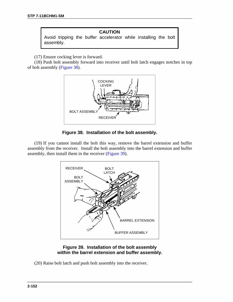
STP 7-11BCHM1-SM
2-152
CAUTIONAvoid tripping the buffer accelerator while installing the boltassembly.
(17) Ensure cocking lever is forward. (18) Push bolt assembly forward into receiver until bolt latch engages notches in top of bolt assembly (Figure 38).
BOLT ASSEMBLY
COCKINGLEVER
RECEIVER
Figure 38. Installation of the bolt assembly.
(19) If you cannot install the bolt this way, remove the barrel extension and buffer assembly from the receiver. Install the bolt assembly into the barrel extension and buffer assembly, then install them in the receiver (Figure 39).
BOLTLATCH
BUFFER ASSEMBLY
RECEIVER
BARREL EXTENSION
BOLTASSEMBLY
Figure 39. Installation of the bolt assembly within the barrel extension and buffer assembly.
(20) Raise bolt latch and push bolt assembly into the receiver.

STP 7-11BCHM1-SM
2-153
(21) Align holes in bolt assembly with stud assembly hole in receiver and install bolt stud in hole in bolt assembly. Place bolt in forward position (Figure 40).
BOLTASSEMBLY
HOLE INBOLT
ASSEMBLYBOLT STUD
RECEIVER
STUDASSEMBLY
HOLE
Figure 40. Installation of the bolt assembly.
f. Assemble driving spring rod assembly (Figure 41). Install the driving spring rod assembly in the upper right corner of the bolt. Push forward and to the right until the driving spring rod assembly engages in the hole in the side plate of the receiver—not in the groove for the backplate.
SIDEPLATE OF
RECEIVER
DRIVINGSPRING RODASSEMBLY
Figure 41. Installation of the driving spring rod assembly.

STP 7-11BCHM1-SM
2-154
g. Install backplate assembly (Figure 42).
RECEIVERGROOVES
BACKPLATELATCH HOOK
BACKPLATEASSEMBLY
BACKPLATE LATCH
Figure 42. Installation of the backplate assembly.
(1) Align backplate assembly with receiver grooves. Pull backplate latch lock while lifting up on backplate latch. Lower backplate assembly down until engaged in receiver. (2) Test proper locking by pulling up on backplate assembly. h. Assemble barrel assembly. (1) Retract bolt far enough for barrel locking spring lug to center in barrel locking spring hole on right side of receiver. (2) Place the smallest loop of a caliber .50 link between the trunnion block and the barrel extension. This holds the barrel locking spring lug aligned with the 3/8-inch hole. (3) Install and screw barrel assembly completely into receiver. Unscrew barrel assembly two clicks and check headspace. 7. Perform a function check to make sure weapon is assembled correctly. a. Place the weapon in the single-shot mode. b. Open the cover and pull the retracting slide handle to the rear. Bolt should lock to rear in single shot mode. c. Hold the retracting slide handle to the rear; depress bolt latch release and ease the bolt forward. d. Press trigger; weapon should fire. e. Place the weapon in the automatic-fire mode. f. Pull the retracting slide handle to the rear and hold. Bolt should not lock to rear in automatic-fire mode. g. Release pressure on the retracting slide handle and ease the bolt forward. h. Press trigger; weapon should fire.

STP 7-11BCHM1-SM
2-155
EVALUATION PREPARATION
Setup: At the test site, provide the soldier with equipment listed in conditions. Use performance steps in the training outline to evaluate soldier’s performance of the task. Brief Soldier: Tell the soldier that he must clear, disassemble, clean, inspect, lubricate, assemble, and perform a function check on the weapon.
EVALUATION GUIDE Performance Measures
Results
1. Clear the weapon.
P F
2. Disassemble the weapon without damaging any parts.
P F
3. Clean the weapon, components, and ammunition.
P F
4. Identify any damaged, worn, or malfunctioning part.
P F
5. Lubricate weapon using the correct lubrication technique.
P F
6. Assemble weapon in correct sequence without damaging any parts.
P F
7. Perform a function check. P F
FEEDBACK
If the soldier passes all steps, score him GO. If he fails any steps, score him NO-GO, then show him what he did wrong and how to do it correctly.
REFERENCES
Required Related FM 23-65 None TM 9-1005-213-10

STP 7-11BCHM1-SM
2-156
LOAD A CALIBER .50 M2 MACHINE GUN 071-022-0003
CONDITIONS Given a cleared caliber .50 machine gun, mounted on a tripod or cupola, and linked caliber .50 ammunition. STANDARDS Load the linked ammunition in the feed tray groove so that, when the cover is closed, a round remains in the tray groove and the ammunition will feed correctly.
EVALUATION PREPARATION
Setup: Provide the soldier with equipment and materials listed in the conditions. You can evaluate this task in a classroom or training area using dummy linked caliber .50 ammunition.
Brief Soldier: Tell the soldier to load the weapon using the belt of ammunition.
EVALUATION GUIDE Performance Measures
Results
1. Ensure the bolt is forward and the cover is closed.
P F
2. Insert the double-loop end of the belt into the feedway until the belt-holding pawl is holding holds the first round.
P F
3. Pull the retracting slide handle to the rear and release it. If the boltlatch release is up, return the retracting slide handle to the forwardposition, then release the bolt.
P F
4. Pull the retracting slide handle to the rear a second time and release it.When the bolt goes forward the second time, the gun is loaded.
P F
FEEDBACK If the soldier passes all steps, score him GO. If he fails any steps, score him NO-GO, then show him what he did wrong and how to do it correctly.

STP 7-11BCHM1-SM
2-157
REFERENCES Required Related FM 23-65 None TM 9-1005-213-10

STP 7-11BCHM1-SM
2-158
SET HEADSPACE AND TIMING ON A CALIBER .50 M2 MACHINE GUN
071-313-3455 CONDITIONS Given a caliber .50 machine gun (tripod or cupola mounted), a headspace and timing gauge, and an assistant gunner. STANDARDS Adjust headspace so that the GO end of the headspace gauge will enter the T-slot and the NO GO end will not. Set timing for the weapon to fire when recoiling parts are between 0.020 and 0.116 inch out of battery.
TRAINING AND EVALUATION Training Information Outline
WARNINGMake sure the gun is clear of ammunition before starting.
1. Adjust headspace. a. Raise the cover group all the way up (Figure 1). b. Grasp the retracting slide handle with your right hand, palm up; pull the bolt to the rear until the barrel locking spring lug aligns with the 3/8-inch hole in the right side plate of the receiver (Figure 2).
COVERGROUP
Figure 1. Raising the cover group.

STP 7-11BCHM1-SM
2-159
3/8-INCHHOLE
RETRACTINGSLIDE HANDLE
Figure 2. Retracting the bolt.
c. Screw the barrel fully into the barrel extension; then unscrew the barrel two notches (clicks) (Figure 3).
BARRELEXTENSION
Figure 3. Screwing the barrel into the barrel extension.
d. Release the retracting slide handle and allow the bolt to go forward slowly.
WARNING• Check the barrel to make sure it is locked in the forward
position. Try to turn the barrel in either direction. Thebarrel should not turn. If it does, stop and notify yoursupervisor or unit armorer at once.
• DO NOT try to fire the gun.

STP 7-11BCHM1-SM
2-160
e. Make sure the weapon is in single-shot mode. Pull the bolt to the rear and hold it; then press the bolT-latch release, and allow the bolt to go forward slowly. Do not fire the weapon. f. Pull the retracting slide handle back, until the barrel extension separates (not more than 1/16 of an inch) from the trunnion block. Make sure the GO/NO GO gauge (Figure 4) has no broken, bent, rusted, or pitted areas, or other defects that could affect the weapon’s dimensional tolerances. g. Raise the cartridge extractor. Try to insert each end of the GO/NO GO headspace gauge in the T-slot between the face of the bolt and the rear of the barrel (Figure 5).
“GO” END
“NO GO”END
TIMINGGAUGES
“NO FIRE”
“FIRE”GAUGE
HEADSPACEGAUGE
Figure 4. Headspace and timing gauge.
“NO GO” END
“GO” END
EXTRACTOR
BOLTFACE BOLT
FACEEND OFBARREL
Figure 5. Checking headspace.
(1) If the GO end of the gauge enters freely up to the ring on the center of the gauge, and the NO/GO end will not enter, the headspace is set correctly. (2) If the GO end of the gauge will not enter T-slot freely, adjust headspace as follows:

STP 7-11BCHM1-SM
2-161
(a) Retract the bolt so you can see the barrel-locking lug spring in the center of the receiver hole on the right side of the receiver (Figure 2). (b) Unscrew the barrel from the barrel extension one notch (click) at a time, until the GO end of the gauge enters the T-slot freely (check after each click). To complete the adjustment, try to insert the NO GO end of the gauge. If it will not enter the T-slot, the headspace is set correctly. (3) If the NO GO end of the gauge enters the T-slot, adjust as follows: (a) Retract the bolt so you can see the barrel locking lug spring in center of receiver hole on right side of receiver (Figure 2). (b) Screw the barrel into the barrel extension one notch (click) at a time, until the NO GO end of the gauge will not enter the T-slot (check after each click). To complete the adjustment, try to insert the GO end of the gauge. If it inserts into the T-slot easily, the headspace is set correctly.
CAUTION• After you have corrected the headspace, recheck the barrel's
positive locking action by trying to screw it in or out with thebolt in the forward position. If you can do either, then DONOT fire the machine gun.
• Notify your supervisor or the unit armorer.
2. Check and adjust timing. a. Check timing. (1) Make sure you have set the headspace correctly. (2) Pull the bolt to the rear with the retracting slide to cock the machine gun. While holding the handle to the rear, depress the bolt latch release, and allow the bolt to go forward slowly. Do not press the trigger. (3) Retract the bolt just enough (1/16 inch) to insert the NO-FIRE gauge between the barrel extension and trunnion block, with the beveled edge of the gauge against the notches in the barrel. Release the retracting slide handle slowly (Figure 6). (4) Depress the trigger. The gun should not fire. If it does not, continue the timing check. However, if it does fire, go to Task Step 2b. (5) Grasp the retracting slide handle. Retract the bolt just enough (1/16 inch) to remove the NO-FIRE gauge. Insert the FIRE gauge between the barrel extension and trunnion block, with the beveled edge of the gauge against the notches in the barrel (Figure 7). Release the retracting slide handle slowly. (6) Depress the trigger. The gun should fire. If it does not, go to Task Step 2b.
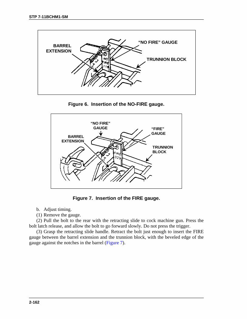
STP 7-11BCHM1-SM
2-162
“NO FIRE” GAUGE
TRUNNION BLOCK
BARRELEXTENSION
Figure 6. Insertion of the NO-FIRE gauge.
TRUNNIONBLOCK
BARRELEXTENSION
“FIRE”GAUGE
“NO FIRE”GAUGE
Figure 7. Insertion of the FIRE gauge.
b. Adjust timing. (1) Remove the gauge. (2) Pull the bolt to the rear with the retracting slide to cock machine gun. Press the bolt latch release, and allow the bolt to go forward slowly. Do not press the trigger. (3) Grasp the retracting slide handle. Retract the bolt just enough to insert the FIRE gauge between the barrel extension and the trunnion block, with the beveled edge of the gauge against the notches in the barrel (Figure 7).

STP 7-11BCHM1-SM
2-163
WARNING• DO NOT remove the backplate unless the bolt is in the
forward position.• Never cock the gun with the backplate off.• Stand to one side of the weapon when removing the
backplate to avoid possible injury from the drivingspring rod.
(4) Move to the side of the gun and remove the backplate. (5) Screw the timing adjustment nut all the way down (to the left). The nut should turn hard (Figure 8). (6) Try to fire by pushing firmly up on the trigger lever (Figure 9). The gun should not fire.
TIMINGADJUSTMENTNUT
Figure 8. Timing adjustment nut.
TRIGGERLEVER
Figure 9. Trigger lever.
(7) Screw the timing adjustment nut up (to the right), one click at a time. Push up firmly on the trigger lever after each click. Repeat until the gun fires.

STP 7-11BCHM1-SM
2-164
(8) Turn the timing adjustment nut up (to the right), two more clicks. Do not turn the timing adjustment nut any more. (9) Remove the FIRE gauge, and replace the backplate. (10) Recheck timing with the FIRE/NO-FIRE gauge twice more to confirm that the adjustment is correct.
EVALUATION PREPARATION
Setup: At the test site, provide the equipment listed in the task conditions statement. Use the performance steps in the training information outline to evaluate performance of the task. Brief Soldier: Tell the soldier to check for and set the correct headspace and timing on the gun.
EVALUATION GUIDE Performance Measures
Results
1. Adjust headspace.
P F
2. Check and set timing. P F
FEEDBACK If the soldier passes all steps, score him GO. If he fails any steps, score him NO-GO, then show him what he did wrong and how to do it correctly.
REFERENCES
Required Related FM 23-65 None TM 9-1005-213-10

STP 7-11BCHM1-SM
2-165
ENGAGE TARGETS WITH A CALIBER .50 M2 MACHINE GUN 071-313-3454
CONDITIONS Given a zeroed caliber .50 machine gun (tripod or cupola mounted), linked caliber .50 ammunition, and a sector of fire with engageable targets. STANDARDS Fire the caliber .50 machine gun to engage targets in your assigned sector of fire. Apply the correct target-engagement techniques so that the entire target is covered with fire.
TRAINING AND EVALUATION Training Information Outline
1. Assume a suitable firing position. Based on your situation, assume a firing position that will allow you to observe and engage targets, but that will reduce your exposure to enemy fire. a. Prone position (Figure 1). b. Sitting position (Figure 2). c. Standing position (Figure 3). d. Standing position for cupola-mounted gun (Figure 4). e. Standing position for HMMWV-mounted gun (Figure 5).
Figure 1. Prone position (tripod mount).
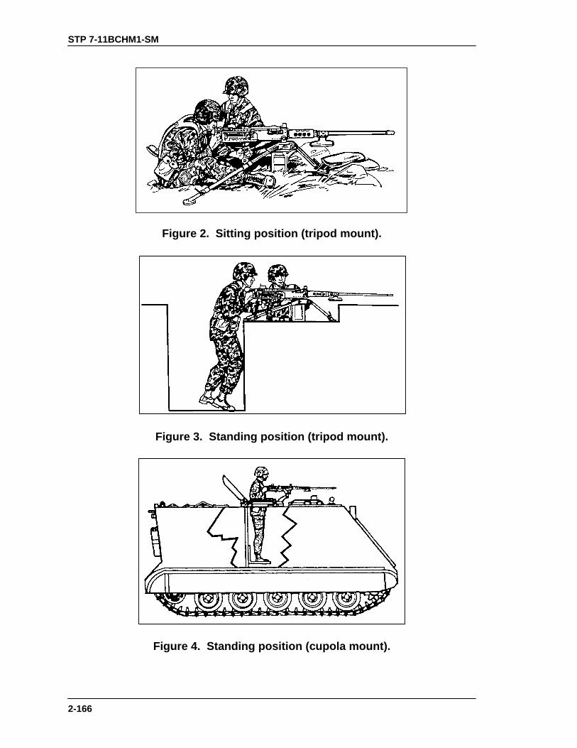
STP 7-11BCHM1-SM
2-166
Figure 2. Sitting position (tripod mount).
Figure 3. Standing position (tripod mount).
Figure 4. Standing position (cupola mount).
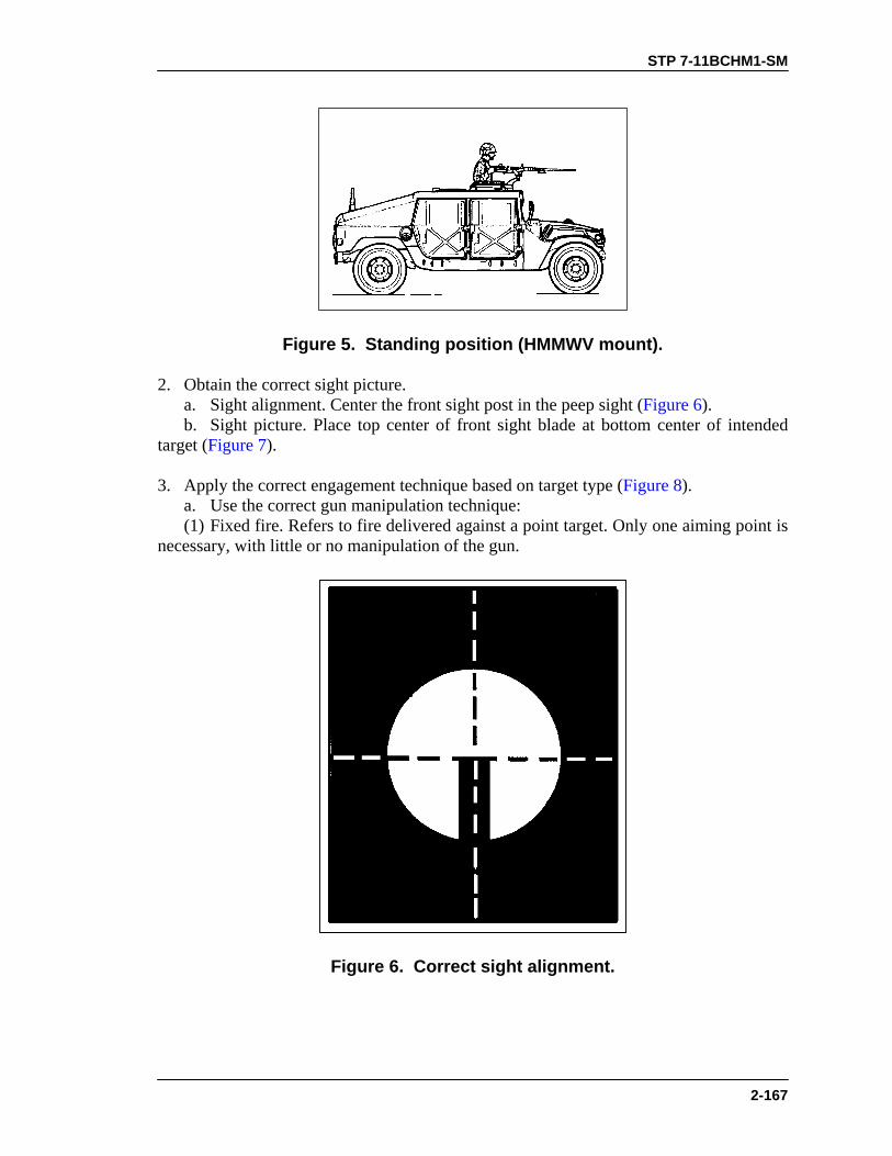
STP 7-11BCHM1-SM
2-167
Figure 5. Standing position (HMMWV mount).
2. Obtain the correct sight picture. a. Sight alignment. Center the front sight post in the peep sight (Figure 6). b. Sight picture. Place top center of front sight blade at bottom center of intended target (Figure 7). 3. Apply the correct engagement technique based on target type (Figure 8). a. Use the correct gun manipulation technique: (1) Fixed fire. Refers to fire delivered against a point target. Only one aiming point is necessary, with little or no manipulation of the gun.
Figure 6. Correct sight alignment.

STP 7-11BCHM1-SM
2-168
Figure 7. Correct sight picture.
(2) Traversing fire. Refers to fire distributed against a wide target, requiring successive changes in the gun direction. To distribute fire laterally, use the T&E mechanism to traverse the gun left or right. (3) Searching fire. Refers to fire delivered against a deep target or a linear target with depth by successively changing elevation. To distribute fire in depth, use the T&E mechanism to move the muzzle of the weapon up or down. (4) Traversing and searching fire. Refers to fire delivered in width and depth by successive changes in direction and elevation. Use this type of fire against a target whose long axis is oblique to the direction of fire. (5) Swinging traverse. Refers to fire delivered against targets that require major changes in direction but little or no change in elevation. Loosen the traversing slide lock enough to swing the gun laterally. (6) Free gun. Refers to fire delivered against moving targets that must be rapidly engaged with fast changes in direction and elevation. To fire free gun, remove the T&E mechanism.

STP 7-11BCHM1-SM
2-169
TRAVERSEAND SEARCH
SEARCHTRAVERSEFIXED
FREE GUNSWINGINGTRAVERSE
Figure 8. Techniques of fire with respect to the gun.
b. Correctly apply fire to engage specific targets. (1) Point target. Engage point targets with fixed fire using a single aiming point (Figure 9).
Figure 9. Point target.
(2) Linear target. Initially aim at the midpoint of the target. Traverse fire to one flank and then to the other to cover the entire target (Figure 10).
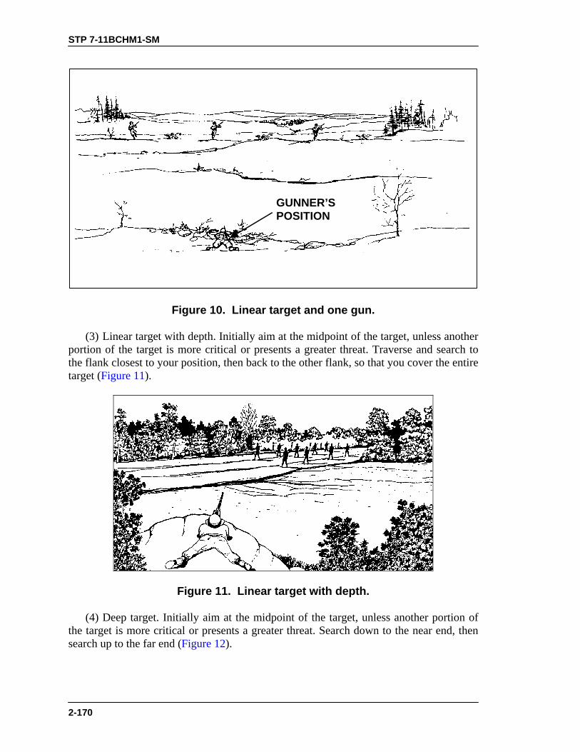
STP 7-11BCHM1-SM
2-170
GUNNER’SPOSITION
Figure 10. Linear target and one gun.
(3) Linear target with depth. Initially aim at the midpoint of the target, unless another portion of the target is more critical or presents a greater threat. Traverse and search to the flank closest to your position, then back to the other flank, so that you cover the entire target (Figure 11).
Figure 11. Linear target with depth.
(4) Deep target. Initially aim at the midpoint of the target, unless another portion of the target is more critical or presents a greater threat. Search down to the near end, then search up to the far end (Figure 12).

STP 7-11BCHM1-SM
2-171
Figure 12. Deep target.
(5) Area target. Initially aim at midpoint of the target area. Traverse and search to either flank, then traverse and search to the opposite flank (Figure 13). 4. Observe fire and adjust the aiming point to place effective fire on the target. a. Observation of fire. Observe bursts of fire by noting tracers in flight or the strike of the rounds in the target area. b. Adjusted aiming point. Adjust fire quickly without adjusting the sight. If the initial burst misses the target, rapidly select a new aiming point the same distance from the center of impact of the initial burst but in the opposite direction. Fire a second burst (Figure 14). 5. Fire on the targets until they are all destroyed, or until you receive an order to cease fire.

STP 7-11BCHM1-SM
2-172
Figure 13. Engagement of area targets.
BEATEN ZONE OFINITIAL BURST
INITIAL AIMING POINT
BEATEN ZONE OF SUBSEQUENT BURST
NEW AIMING POINT
Figure 14. Adjusted aiming point method.
EVALUATION PREPARATION
Setup: Evaluate this task on a 10-meter live-fire range equipped with the basic machine gun target pasters (FSN 6920-078-5128). Provide the soldier with a caliber .50 M2 machine gun (tripod mounted) with 236 rounds of linked .50 caliber ammunition (117 rounds for practice and 119 rounds for qualification). Conduct 10-meter firing IAW Table I, Appendix C, FM 23-65.

STP 7-11BCHM1-SM
2-173
Brief Soldier: Tell the soldier he will fire Table I IAW Appendix C, FM 23-65 (brief the conditions, standards, and ammunition). Tell the soldier that when you instruct him to fire, you will evaluate his ability to apply correct target engagement techniques and to place effective fire on targets.
EVALUATION GUIDE
Performance Measures
Results
1. Assume a suitable firing position.
P F
2. Apply correct engagement technique based on target type. a. Use correct gun manipulation technique. b. Use correct application of fire to engage specific targets.
P F
3. Place effective fire on targets (score a minimum of 84 points). P F
FEEDBACK
If the soldier passes all steps, score him GO. If he fails any steps, score him NO-GO, then show him what he did wrong and how to do it correctly.
REFERENCES
Required Related FM 23-65 None TM 9-1005-213-10

STP 7-11BCHM1-SM
2-174
CORRECT MALFUNCTIONS OF A CALIBER .50 M2 MACHINE GUN
071-022-0005 CONDITIONS Given a loaded caliber .50 M2 machine gun, mounted on a tripod or cupola, a sector of fire, an assistant gunner, linked caliber .50 ammunition, a ruptured cartridge extractor, a cleaning rod, cleaner lubricant preservative (CLP), lubricating oil arctic weather (LAW), cleaning swabs, and a headspace and timing gauge. The caliber .50 machine gun has been firing and one of the following situations has developed: The weapon has failed to fire; the weapon continues to fire after the trigger is released (uncontrolled fire); or the weapon is firing sluggishly. STANDARDS Within 5 seconds after a caliber .50 machine gun fails to fire, take immediate action to return the weapon to service. Do not identify the cause of the malfunction. If immediate action is unsuccessful, perform remedial action. Identify the cause of the malfunction. Take immediate action to secure a runaway caliber .50 machine gun; then take remedial action to eliminate the malfunction. Take corrective action for a caliber .50 machine gun that is firing sluggishly.
TRAINING AND EVALUATION Training Information Outline
1. Take immediate action to correct a failure to fire. a. On a cool weapon, that is, one that has fired fewer than 150 rounds in 2 minutes— (1) Hold the weapon on target. (2) Wait 5 seconds in case the weapon has a hangfire. (3) Pull the bolt to the rear. Return the retracting slide handle to its forward position. If the bolt locks to the rear, depress the bolt latch to return the bolt to the forward position. (4) Try to fire. If the weapon fires, you have corrected the stoppage. (5) If the weapon fails to fire, wait 5 seconds, pull the bolt to the rear, and lock it in the rearward position (engage with bolt latch). Return the retracting slide handle to its forward position. (6) Proceed to Step 2, remedial action. b. On a hot weapon, that is, one that has fired 150 or more rounds in 2 minutes— (1) Hold the weapon on target. (2) Wait 5 seconds in case there is a hangfire. (3) Within the next 5 seconds, pull the bolt to the rear, return the retracting slide handle to its forward position, and try to fire. If the weapon fires, you have corrected the stoppage.

STP 7-11BCHM1-SM
2-175
(4) If the weapon fails to fire, or if you were unable to retract the bolt during Step 1b(3), then you must keep the cover closed and wait 15 minutes to allow the weapon to cool. (5) Go to Step 2.
DANGERNEVER OPEN THE COVER ASSEMBLY ON A HOTWEAPON. THE WEAPON COULD COOK OFF, WHICHCOULD DAMAGE THE WEAPON AND, MOREIMPORTANTLY, COULD KILL OR INJURE PERSONNEL.APPLY IMMEDIATE ACTION TO A HOT WEAPON WITHIN 10SECONDS. IF YOU ARE UNABLE TO EITHER FIRE ORREMOVE THE ROUND WITHIN 10 SECONDS, THEN YOUMUST WAIT ANOTHER 15 MINUTES BEFORE YOU CAN DOANYTHING ELSE TO THE WEAPON.
2. Take remedial action. a. Open the cover assembly and check for faulty ammunition or an obstruction in the barrel assembly and chamber. b. If a cartridge is in the T-slot of the bolt, and if it does not fall out, then hold the bolt to the rear, raise the extractor, and use a screwdriver to push the cartridge out the bottom of the receiver. c. If a ruptured (separated) cartridge case is in the T-slot, remove it with a cleaning rod or ruptured cartridge extractor. (1) When using the ruptured extractor, raise the cover. Pull and lock the bolt to the rear. Place the extractor in the T-slot the same way you would with a cartridge. Use the gun’s extractor assembly ejector to hold the extractor in line with the bore. When the extractor is aligned with the bore, let the bolt go forward into the ruptured case. The shoulders will spring out in front of the case. Pull the bolt to the rear and remove the ruptured case and extractor. (2) When using a cleaning rod, raise the cover. Pull and lock the bolt to the rear. Insert the cleaning rod in the front end of the barrel. Gently push the ruptured cartridge from the chamber. d. Reload and try to fire the weapon. If the weapon does not fire, continue remedial action. e. Disassemble the weapon and inspect for dirt, obstructions, and defective parts. f. Clean the weapon, remove obstructions, and replace defective parts. Lubricate and assemble the weapon. g. Set or adjust headspace and timing. h. Replace faulty ammunition. i. If the weapon still fails to fire, notify your supervisor.
STP 7-11BCHM1-SM
2-176
3. Take immediate action to stop uncontrolled automatic fire (runaway gun). a. Perform one of three actions: • Hold the weapon on target until it stops firing. • Have the assistant gunner twist the belt, causing the gun to jam. • Allow the weapon to fire remaining ammunition. b. If you have fired all your ammunition, check to ensure the weapon is clear, and go to Step 3c. If you have not fired all your ammunition, and the weapon is hot (it has fired more than 150 rounds in less than 2 minutes), keep the cover assembly closed and wait 15 minutes, then proceed to Step 3c. c. Disassemble the weapon and inspect for defective parts. d. Clean the weapon, remove obstructions, replace defective parts, lubricate and assemble the weapon. e. Check headspace and timing, and adjust them if necessary. f. If the weapon still fails to fire properly, notify your supervisor. 4. Correct sluggish operation. a. Clear the weapon. b. Disassemble, clean, and lubricate the weapon. c. Assemble the weapon. d. Set headspace and timing.
EVALUATION PREPARATION
Setup: You can evaluate this task at a test site rather than on a live fire range. Provide the materials and equipment listed in the task conditions statement. Give the soldier caliber .50 linked dummy rounds instead of live rounds. Insert an expended round in the belt to cause a stoppage. Brief Soldier: Tell the soldier to assume a firing position behind the caliber .50 machine gun and to apply any required immediate action. Tell the soldier that the test does not require him or her to perform remedial action. Ask the soldier to describe the actions to perform for remedial action on cold and hot weapons, sluggish operation, and a runaway weapon.

STP 7-11BCHM1-SM
2-177
EVALUATION GUIDE
Performance Measures
Results
1. Take immediate action for failure to fire within 10 seconds. a. Hold the weapon on target. b. Wait 5 seconds in case the weapon has a hangfire. c. Within the next 5 seconds, pull the bolt to the rear, return the retracting slide handle to its forward position, and try to fire. d. If the weapon fails to fire, wait 5 seconds and take appropriate remedial action.
P F
2. Take remedial action on a cool weapon. a. Open the cover assembly. b. Remove the ammunition belt. c. Remove the ruptured cartridge and all obstructions from the T-Slot, barrel assembly, and chamber. d. Reload and fire the weapon. e. If the weapon does not fire, disassemble it, and inspect it for dirt, obstructions, and defective parts. f. Clean the weapon, remove obstructions, replace defective parts, lubricate it, assemble it, and set the headspace and timing. g. Replace faulty ammunition. h. If the weapon still fails to fire, notify your supervisor.
P F
3. Take remedial action on a hot weapon. a. Keep the cover closed and wait 15 minutes to allow the weapon to cool. b. Perform the same procedures as for cool weapon after waiting period.
P F
4. Take action to stop uncontrolled automatic fire (runaway gun). a. Perform one of three actions: • Hold the weapon on target until it stops firing. • Have the assistant gunner twist the belt, causing the gun to jam. • Allow the weapon to fire remaining ammunition. b. Take the appropriate remedial action based on whether the weapon is hot or cold.
P F
5. Correct sluggish operation. a. Clear the weapon. b. Disassemble, clean, and lubricate the weapon. c. Assemble the weapon. d. Set headspace and timing.
P F

STP 7-11BCHM1-SM
2-178
FEEDBACK If the soldier passes all steps, score him GO. If he fails any steps, score him NO-GO, then show him what he did wrong and how to do it correctly.
REFERENCES
Required Related FM 23-65 None TM 9-1005-213-10

STP 7-11BCHM1-SM
2-179
UNLOAD A CALIBER .50 M2 MACHINE GUN 071-022-0004
CONDITIONS Given a caliber .50 M2 machine gun, mounted on a tripod or cupola, loaded with linked caliber .50 ammunition. STANDARDS Remove all ammunition and links from the machine gun. Clear the weapon, ensuring the chamber is empty and the weapon is in the single-shot mode.
EVALUATION PREPARATION Setup: Provide all equipment and materials listed in the task conditions statement. You can evaluate this task in a classroom or training area using dummy linked caliber .50 ammunition. Brief Soldier: Tell the soldier to unload and clear the caliber .50 M2 machine gun.
EVALUATION GUIDE Performance Measures
Results
1. Place the gun in the single-shot mode.
P F
2. Raise the cover.
P F
3. Remove the ammunition belt from the feedway.
P F
4. Close the cover.
P F
5. Pull bolt to the rear and lock it.
P F
6. Raise cover and inspect to make sure there are no rounds inthe chamber.
P F
7. Hold charging handle and release the bolt, allowing it to moveslowly forward.
P F
8. Press the trigger. P F

STP 7-11BCHM1-SM
2-180
FEEDBACK If the soldier passes all steps, score him GO. If he fails any steps, score him NO-GO, then show him what he did wrong and how to do it correctly.
REFERENCES Required Related FM 23-65 None TM 9-1005-213-10

STP 7-11BCHM1-SM
2-181
MK 19 MACHINE GUN
MAINTAIN A MK 19 MACHINE GUN 071-030-0001
CONDITIONS Given a MK 19 machine gun, an M3 tripod, a traversing and elevating (T&E) mechanism, an M64 cradle mount; rifle bore cleaner (RBC) and lubricating oil (LSA), or lubricating oil (LSAT or LAW); grease (GMD); cleaning solvent (PD680); wiping rags or cloth (abrasive crocus); a cleaning rod assembly and a small arms cleaning brush; linked 40-mm ammunition and one spent 40-mm cartridge case. STANDARDS Clean and lubricate the MK 19 and its components. Inspect all parts and turn in those in need of maintenance. Reassemble the gun so that it is operational. Clean and inspect ammunition for serviceability, and turn in any unserviceable ammunition.
TRAINING AND EVALUATION Training Information Outline
1. Clear the MK 19. a. Place the safe/fire switch on the safe (S) position. Ensure the bolt is forward. b. Open the top cover and inspect the feed tray and extractors on the bolt face to ensure that no round is in the pickup position.
WARNINGThe top cover has no mechanical support to hold it open.Avoid allowing it to slam shut. When you do close it, lowerit carefully to prevent personal injury or equipment damage.
c. Unlock and pull the charger handle 2 or 3 inches to the rear; inspect the face of the bolt and the chamber for ammunition. d. Return the bolt to the forward position and rotate the charger handle to the locked position. 2. Disassemble the MK 19. a. Remove the feed throat assembly (Figure 1). Squeeze the two sets of grip pins together and pull them straight out. b. Remove the bolt and backplate assembly.

STP 7-11BCHM1-SM
2-182
GRIPPINS
Figure 1. Removal of feed throat assembly.
WARNINGMake sure the bolt is in the forward position before youremove the backplate pin assembly. Failure to observe thiswarning will result in injury.
(1) Place the safe/fire switch on fire (F). (2) Open the top cover. (3) Using the rim of a spent cartridge, pull the backplate pin straight out (Figure 2).
Figure 2. Removal of backplate pin.
(4) Lift up slightly on the backplate assembly. Slowly pull the bolt and backplate assembly out of the receiver. (5) Support the bolt with one hand and maintain a control grip with the other hand. Lift the bolt up slightly and remove it (Figure 3).
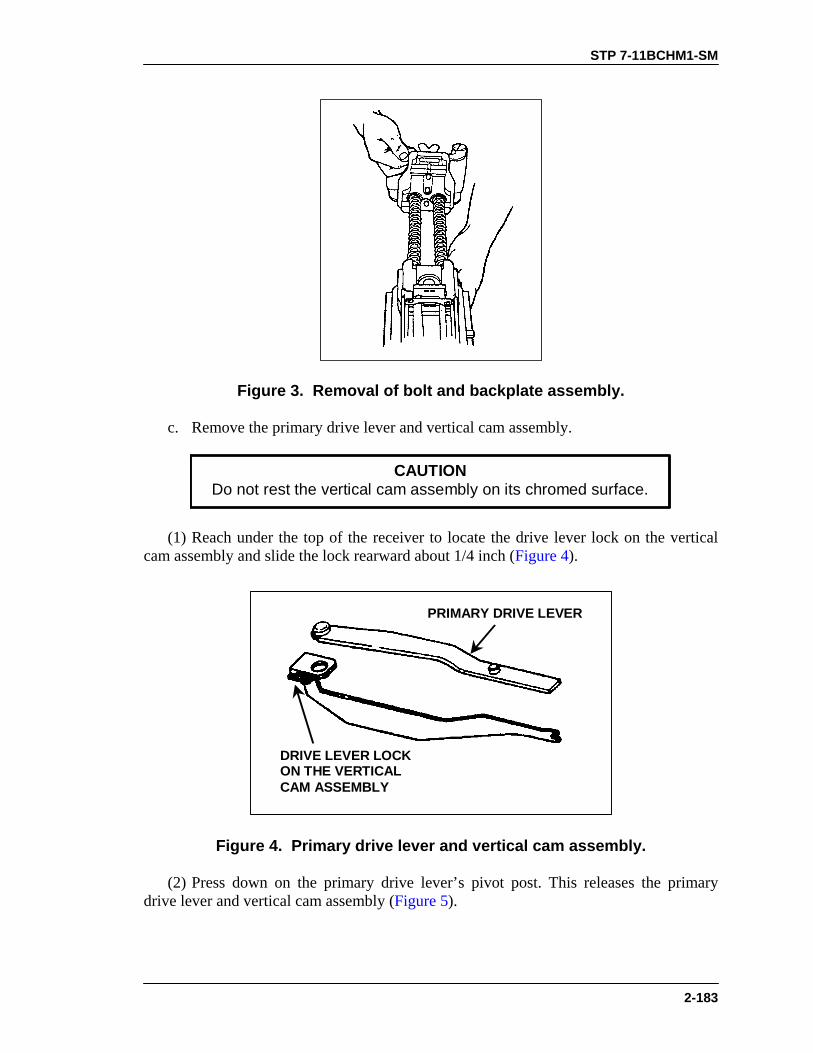
STP 7-11BCHM1-SM
2-183
Figure 3. Removal of bolt and backplate assembly.
c. Remove the primary drive lever and vertical cam assembly.
CAUTIONDo not rest the vertical cam assembly on its chromed surface.
(1) Reach under the top of the receiver to locate the drive lever lock on the vertical cam assembly and slide the lock rearward about 1/4 inch (Figure 4).
DRIVE LEVER LOCKON THE VERTICALCAM ASSEMBLY
PRIMARY DRIVE LEVER
Figure 4. Primary drive lever and vertical cam assembly.
(2) Press down on the primary drive lever’s pivot post. This releases the primary drive lever and vertical cam assembly (Figure 5).

STP 7-11BCHM1-SM
2-184
RECEIVERPIVOT POST
DRIVE LEVER LOCK
Figure 5. Removal of the primary drive lever and vertical cam assembly.
(3) Pull out the cam (to the rear) and the lever from the receiver. d. Remove secondary drive lever. (1) Push down on the pivot post from the outside top cover. This releases the secondary drive lever (Figure 6).
PIVOT POSTSECONDARYDRIVE LEVER
Figure 6. Removal of the secondary drive lever.
(2) Lift out the secondary drive lever from the top cover (Figure 7).

STP 7-11BCHM1-SM
2-185
SECONDARYLEVERLOCK
Figure 7. Secondary drive lever.
e. Remove the feed slide assembly (Figure 8). (1) Pivot the tray that holds the feed slide assembly out of the top cover. (2) Move the feed slide assembly to line up the tabs with the slots in the tray. (3) Lift upward on the feed slide assembly.
SLOTS INTRAY
FEED SLIDE ASSEMBLY
Figure 8. Removal of the feed slide assembly.
f. Remove the top cover assembly and feed tray (Figure 9).
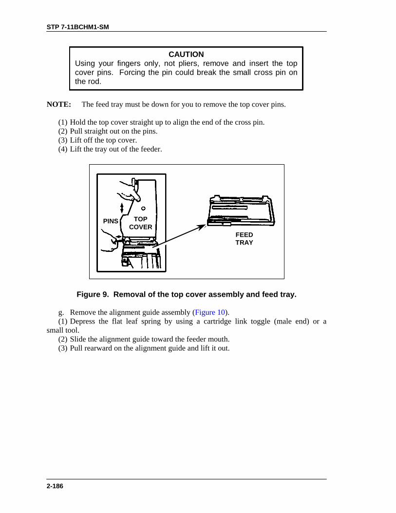
STP 7-11BCHM1-SM
2-186
CAUTIONUsing your fingers only, not pliers, remove and insert the topcover pins. Forcing the pin could break the small cross pin onthe rod.
NOTE: The feed tray must be down for you to remove the top cover pins. (1) Hold the top cover straight up to align the end of the cross pin. (2) Pull straight out on the pins. (3) Lift off the top cover. (4) Lift the tray out of the feeder.
TOPCOVER
PINS
FEEDTRAY
Figure 9. Removal of the top cover assembly and feed tray.
g. Remove the alignment guide assembly (Figure 10). (1) Depress the flat leaf spring by using a cartridge link toggle (male end) or a small tool. (2) Slide the alignment guide toward the feeder mouth. (3) Pull rearward on the alignment guide and lift it out.

STP 7-11BCHM1-SM
2-187
ALIGNMENT GUIDE
FLAT LEAFSPRING
FLAT LEAFSPRING
Figure 10. Removal of the alignment guide assembly.
h. Remove the ogive plunger by pulling it out (Figure 11).
OGIVEPLUNGER
Figure 11. Removal of the ogive plunger.
i. Remove the round positioning block (Figure 12). (1) Push in and slide the round positioning block toward the muzzle end of gun. (2) Pull the round positioning block away from the wall of the receiver.

STP 7-11BCHM1-SM
2-188
SLIDEROUND POSITIONING
BLOCK
Figure 12. Removal of the round positioning block.
j. Remove the charger assemblies (both sides) (Figure 13). (1) Rotate the charger handle up. (2) Using either your fingers or a spent case, pry out on the lip of the lock plunger. (3) Lift up on the lock plunger to retract it; slide the charger assembly all the way to the rear. (4) Pull the charger assembly away from the receiver.
LOCKPLUNGER
CHARGERASSEMBLY
Figure 13. Removal of the charger assembly.
k. Remove the receiver sear assembly (Figure 14). (1) Turn the receiver over on its top. Put the safe/fire switch in fire (F) position. (2) Lift up slightly on the lockpin with your fingers, using a cartridge link. (3) Squeeze the receiver sear (underneath the safety) and simultaneously rotate the sear housing assembly approximately 15 degrees in either direction.

STP 7-11BCHM1-SM
2-189
LOCK PIN
ROTATE
SAFETY
SPRING
SEAR
Figure 14. Removal of the receiver sear assembly.
(4) Press down on the sear housing assembly and rotate the assembly until it stops (90 degrees from its original position). (5) Press the receiver sear and safety together while you put safe/fire switch on safe (S). This locks the sear in the down position and keeps you from accidentally losing the sear spring. (6) Lift out the sear housing assembly. 3. Clean the parts of the MK 19. NOTE: Do not reverse the direction of the bore brush while it is in the bore. a. Clean the receiver assembly (Figure 15). (1) Apply solvent to a rag or brush. Wipe or brush dirt away from all parts, especially the interior of the receiver housing, receiver rails, and feeder. (2) Swab out the bore and chamber, using a bore brush and RBC. (3) Wipe all parts dry. b. Clean the receiver sear assembly (Figure 14). (1) Use only cleaning solvent on a rag or brush. (2) Wipe or brush away dirt. (3) Wipe dry.

STP 7-11BCHM1-SM
2-190
REAR SIGHT
RECEIVERHOUSING
RECEIVER RAILSFLASH
SUPPRESSOR BARREL FEEDER
Figure 15. Receiver assembly.
WARNINGNever immerse the sear housing assembly in solvent.Solvent may dilute the lubricant inside the sear housing.
c. Clean the alignment guide assembly, ogive plunger, round positioning block, and secondary drive lever: Wipe or brush off dirt and dry.
WARNINGNever immerse the ogive plunger assembly in solvent.
d. Clean the charger assemblies. (1) Apply cleaning solvent to a rag or brush, and wipe or brush off any dirt. (2) Wipe dry. e. Clean the vertical cam assembly, primary drive lever, feed slide assembly, and feed tray. (1) Soak in cleaning solvent. (2) Wipe or brush off dirt. (3) Wipe dry. f. Clean the top cover assembly. (1) Apply cleaning solvent to a rag or brush and wipe or brush off dirt from all parts. (2) Wipe all surfaces dry. g. Clean the bolt and backplate assembly. (1) Apply cleaning solvent to rag or brush and wipe or brush off dirt from all parts. (2) Wipe all surfaces dry.

STP 7-11BCHM1-SM
2-191
WARNINGNever immerse the bolt assembly in cleaning solvent.
4. Clean the components. a. Clean the T&E mechanism. (1) Remove foreign matter with a clean, dry wiping rag. (2) Use a small arms cleaning brush to clean the numbers on the scale. b. Clean the M3 tripod, MK64 gun cradle mount, and pintle. (1) Use a cleaning swab saturated with carbon removing compound remove dirt. (2) Wipe all parts dry with clean wiping rags. 5. Clean ammunition: Remove foreign matter with a clean, dry wiping rag. 6. Inspect all MK 19 parts for serviceability. a. Receiver assembly. (1) Check the receiver housing for cracks and rust. (2) Check the receiver rails for burrs and cracked welds. (3) Check the feeder pawls for burrs and lack of spring action. Check the pins for retention. (4) Check the barrel for carbon buildup and pitting in the bore and chamber. (5) Check the flash suppressor for dents, cracks, and erosion. Make sure minimal movement is maintained. (6) Check the rear sight for rust, binding, and broken or bent parts. b. Receiver sear assembly. (1) Check for burrs on all parts. (2) Closely inspect the rear shoulder for burrs. c. Alignment guide assembly. (1) Check the alignment guide spring for deformity, cracks, and looseness. (2) Check the pin for breaks and cracks. d. Ogive plunger assembly and round positioning block. (1) Check the ogive plunger head for burrs and broken parts. (2) Check the round positioning block for weak spring action and loose or broken parts. e. Charger assembly (left and right). (1) Check the grooved edges for burrs and bends. (2) Check the latches for spring action on detents. (3) Check the entire charger assembly for cracks, burrs, bends, and chips. f. Vertical cam assembly and primary drive lever. (1) Check the vertical cam assembly for bends, burrs, pits, scratches, and aluminum buildup on chromed surface (mirror-like surface). (2) Check the drive lever lock for looseness or binding. (3) Check the primary drive lever for burrs, especially around the pivot posts. g. Secondary drive lever. (1) Check for missing retaining ring from the pivot post. (2) Check the pivot post and forked end for burrs.

STP 7-11BCHM1-SM
2-192
h. Feed slide assembly and feed tray. (1) Check the feed pawls and feed tray for burrs and binding. (2) Check the guide rails for burrs. i. Top cover assembly. (1) Check the top cover housing for cracks and rust. (2) Check the latch for binding, looseness, and breaks. (3) Check the cover pin for sheared or broken cross pin. j. Bolt and backplate assembly. (1) Check the cocking lever for chips, burrs, and breaks. (2) Check the guide rods for binding and bends. (3) Check the recoil spring for weak action: Position the bolt end against a hard, flat surface and push up and down on backplate assembly. (4) Check the backplate pin for a missing retaining spring. (5) Check the safety wire for looseness and breaks, or if missing. k. Report any deficiencies to your supervisor. 7. Inspect all components for serviceability. a. T&E mechanism. (1) Inspect the hand wheels for smooth operation and rust. Check the threads for burrs and rust. (2) Check the traversing slide lock for spring action. Make sure the elevating mechanism sleeve fits on the traversing bar and clamps firmly. (3) Check the traversing and elevating scales for legibility. (4) Insect the quick release pin and chain for burrs and rust; check for missing spring-loaded balls. b. M3 Tripod. (1) Check for completeness of tripod; make sure all nuts and bolts are tightly secured. (2) Check for cracks on the legs and tripod head. (3) Check for missing, broken, or inoperative lock latch. (4) Check the pintle lock release cam for correct operation. (5) Check the locking action of the front leg clamping assembly. (6) Make sure the rear legs lock in the open position, the sleeve latch notch and the right leg slide notch engage completely, and the latch spring has good tension. (7) Check the telescoping, indexing, and locking actions of rear legs and front leg locking assembly. c. MK 64 gun cradle mount. (1) Check for missing or damaged parts. (2) Check for rust, cracks, and burrs. (3) Inspect pintle lock assembly for nut, bolt, and cotter pin. Check the pintle surface for burrs and rust. d. Report any deficiencies to supervisor. 8. Inspect ammunition for damage and corrosion. Turn in any unserviceable ammunition.

STP 7-11BCHM1-SM
2-193
9. Lubricate the MK 19 and components. Do not use CLP, and do not mix lubricants.
CAUTION1. Never immerse the sear housing, ogive plunger, or bolt
assemblies in cleaning solvent. Solvent could dilute thelubricant or grease inside.
2. Never lubricate MK 19 with CLP.3. Avoid mixing lubricants.4. Completely wipe off all excess lubricant.
a. Lubricate lightly to moderately with LSAT, LSA, or GMD (never CLP). In cold weather (0° to minus 25° Fahrenheit), use LSAT, LSA, GMD, or LAW. In extra cold weather (-25°Fahrenheit and below) use LAW. b. Apply lubricant to all weapon parts and surfaces except charger handles. Work in the lubricant by moving the parts. c. Lubricate all components and wipe them with an oily rag to remove excess oil. 10. Assemble the MK 19 machine gun. a. Attach the charger assemblies (both sides) (Figure 16). (1) Turn the receiver upright. (2) Rotate the charger handles to the straight-up position. (3) Line up the lugs on the charger with the slots in the receiver rail. Insert the charger lugs into the slots. (4) Hold the charger tightly against the rail. Slide the charger forward until it locks into place.
LUGSSLOTS
CHARGERHANDLE
Figure 16. Attachment of the charger assemblies.
b. Attach the round positioning block (Figure 17). (1) Insert the blocks into the slots with the tang end forward. (2) Push against the block and slide it toward the rear until the block locks into place.

STP 7-11BCHM1-SM
2-194
TANG END
Figure 17. Attachment of the round positioning block.
c. Insert the ogive plunger assembly into the opening. d. Insert the alignment guide assembly (Figure 18). (1) Position the alignment guide assembly so that the pin is lined up with the slot in the feeder wall. (2) Hold the alignment guide against the front wall and slide the alignment guide into the receiver until it clicks.
FRONTWALL
ALIGNMENTGUIDEASSEMBLY
Figure 18. Insertion of the alignment guide assembly.
e. Attach the feed tray and feed slide assembly (Figure 19). (1) Place the tray in the top of the feeder, recessed side up. (2) The pinholes on the tray should line up with the lugs on the receiver. (3) Position the feed slide assembly by lining up the tabs with the slots on the tray. (4) Insert the tabs into the slots. Drop the feed slide assembly into the tray and move it slightly to ensure engagement.

STP 7-11BCHM1-SM
2-195
SLOTS INTRAY
LUGS ONRECEIVER
Figure 19. Attachment of the feed slide assembly.
f. Attach the top cover assembly (Figure 20). (1) Ensure the feed tray is in the proper place in the receiver. (2) Place the top cover on the receiver. Line up the pinholes on the cover with the receiver’s lug end and the pinholes on the feed tray. (3) Hold the top cover straight up. Insert the top cover pins on both sides. Fully insert the cross pin. Rotate the top cover so that it is fully open.
WARNINGTo avoid breaking the cross pin, be sure to insert it fullyinto the receiver before you close the top cover.
TOPCOVER
PINS
TOPCOVER
FEED TRAYPINHOLES
Figure 20. Attachment of the top cover assembly.
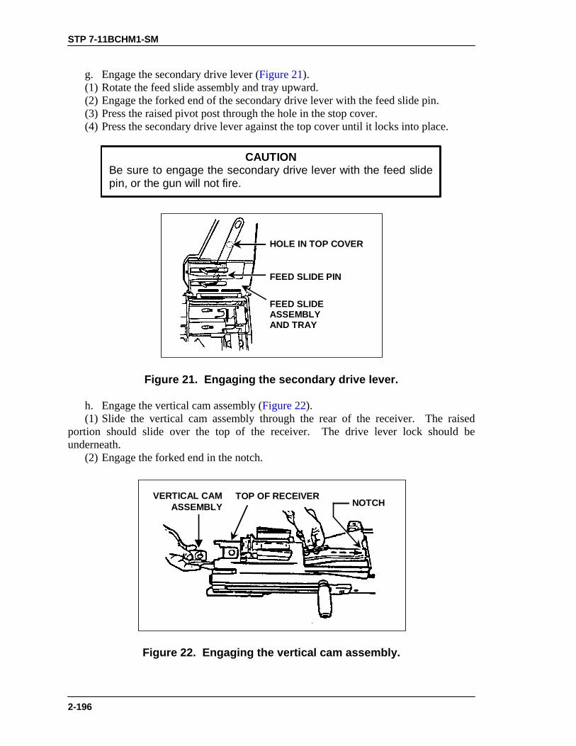
STP 7-11BCHM1-SM
2-196
g. Engage the secondary drive lever (Figure 21). (1) Rotate the feed slide assembly and tray upward. (2) Engage the forked end of the secondary drive lever with the feed slide pin. (3) Press the raised pivot post through the hole in the stop cover. (4) Press the secondary drive lever against the top cover until it locks into place.
CAUTIONBe sure to engage the secondary drive lever with the feed slidepin, or the gun will not fire.
FEED SLIDEASSEMBLYAND TRAY
HOLE IN TOP COVER
FEED SLIDE PIN
Figure 21. Engaging the secondary drive lever.
h. Engage the vertical cam assembly (Figure 22). (1) Slide the vertical cam assembly through the rear of the receiver. The raised portion should slide over the top of the receiver. The drive lever lock should be underneath. (2) Engage the forked end in the notch.
VERTICAL CAMASSEMBLY
TOP OF RECEIVERNOTCH
Figure 22. Engaging the vertical cam assembly.
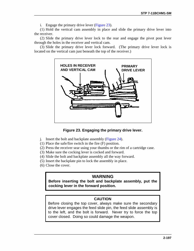
STP 7-11BCHM1-SM
2-197
i. Engage the primary drive lever (Figure 23). (1) Hold the vertical cam assembly in place and slide the primary drive lever into the receiver. (2) Slide the primary drive lever lock to the rear and engage the pivot post lever through the holes in the receiver and vertical cam. (3) Slide the primary drive lever lock forward. (The primary drive lever lock is located on the vertical cam just beneath the top of the receiver.)
HOLES IN RECEIVERAND VERTICAL CAM
PRIMARYDRIVE LEVER
Figure 23. Engaging the primary drive lever.
j. Insert the bolt and backplate assembly (Figure 24). (1) Place the safe/fire switch in the fire (F) position. (2) Press the receiver sear using your thumbs or the rim of a cartridge case. (3) Make sure the cocking lever is cocked and forward. (4) Slide the bolt and backplate assembly all the way forward. (5) Insert the backplate pin to lock the assembly in place. (6) Close the cover.
WARNINGBefore inserting the bolt and backplate assembly, put thecocking lever in the forward position.
CAUTIONBefore closing the top cover, always make sure the secondarydrive lever engages the feed slide pin, the feed slide assembly isto the left, and the bolt is forward. Never try to force the topcover closed. Doing so could damage the weapon.

STP 7-11BCHM1-SM
2-198
RECEIVERSEAR
COCKINGLEVER
Figure 24. Insertion of the bolt and backplate assembly.
k. Attach the receiver sear assembly (Figure 25). (1) Turn the receiver over on its top. (2) Place the sear housing on the receiver and line up the sear housing assembly at a right angle to the barrel centerline. (3) Put the safe/fire switch on fire (F) position. (4) Press down and rotate the housing assembly until it stops. (5) Press up on the sear and rotate it until it locks in position.
TWIST 90°
CENTERLINE
Figure 25. Attachment of the receiver sear assembly.
l. Attach the feed throat assembly. (1) Squeeze the grip pins and align them with the holes in the receiver. (2) Release the grip pins to attach the feed throat. 11. Perform a function check to make sure you have assembled the weapon correctly (see Task 071-030-0007, Perform a Function Check on a MK 19 Machine Gun).

STP 7-11BCHM1-SM
2-199
EVALUATION PREPARATION
Setup: At the test site, provide the soldier with the equipment listed in the task conditions statement. Use the performance steps in the training outline to evaluate the soldier’s performance of the task. Brief Soldier: Tell the soldier to perform operator level maintenance on the MK 19 and to perform a function check to ensure the weapon functions correctly.
EVALUATION GUIDE Performance Measures
Results
1. Clear the weapon.
P F
2. Disassemble the weapon without damaging any parts.
P F
3. Clean the weapon parts.
P F
4. Clean the components.
P F
5. Clean the ammunition.
P F
6. Inspect all parts, components, and ammunition for serviceability.
P F
7. Report all deficiencies to your supervisor.
P F
8. Lubricate the weapon parts and components using the correct lubricantand lubrication techniques.
P F
9. Assemble the weapon in the correct sequence without damaging any parts.
P F
10. Perform a function check. P F
FEEDBACK If the soldier passes all steps, score him GO. If he fails any steps, score him NO-GO, then show him what he did wrong and how to do it correctly.

STP 7-11BCHM1-SM
2-200
REFERENCES
Required Related FM 23-27 None TM 9-1010-230-10

STP 7-11BCHM1-SM
2-201
MOUNT A MK 19 MACHINE GUN ON AN M3 TRIPOD 071-030-0011
CONDITIONS Given a sector of fire, an assistant gunner, and a MK 19 machine gun with feed throat assembly, MK64 gun mount, M3 tripod, and T&E mechanism. STANDARDS Ground mount the MK 19 machine gun on the M3 tripod without damage to equipment or injury to personnel.
TRAINING AND EVALUATION Training Information Outline
WARNINGA two-man lift is required for the MK 19 machine gun andeach fully loaded M548 ammunition container.DO NOT try to lift either by yourself.
1. Set up the M3 tripod. a. Select a level and stable location and position the tripod so that the gun will be oriented toward the assigned sector of fire. b. Open and lock the rear legs of the tripod in the open position (Figure 1).
LIFT ANDSPREAD
Figure 1. Positioning the tripod.

STP 7-11BCHM1-SM
2-202
c. Open and adjust the front leg of the tripod so that it forms an angle of about 60 degrees to the ground. Stabilize the legs of the tripod by pushing the metal shoe of each leg into the ground, or sandbag each leg. 2. Attach the T&E mechanism a. Lock the T&E mechanism in the center of traversing bar (Figure 2). b. Rotate the elevation handwheel to the middle of the threaded shaft and position the traversing handwheel on the left side.
LEG-CLAMPINGHANDLE
ELEVATINGMECHANISM
INDEXING LEVERASSEMBLY
PINTLE LOCKRELEASE CAM
FRONT LEGCLAMP HANDLE
TRAIL LEGS
TRAVERSING BAR
TRIPOD HEAD
FRONTLEG
REAR RIGHT LEGSLIDING SLEEVE
Figure 2. M3 tripod.
3. Attach MK64 gun mount. a. Lift the pintle lock release cam until it locks open. b. Place the MK64 gun mount pintle into the tripod (Figure 3) until it sits flush on the tripod head. Flip down the pintle lock on the tripod. c. Make sure the gun mount is locked into the tripod by lifting slightly on the gun mount. d. Disengage the stow pin (Figure 4) from the gun mount. e. Remove the quick release pin from the T&E mechanism. Align the holes in the T&E mechanism with the rear holes of the gun mount. Insert the quick release pin from the right side, and rotate the pin downward to the locked position (Figure 5 and Figure 6).
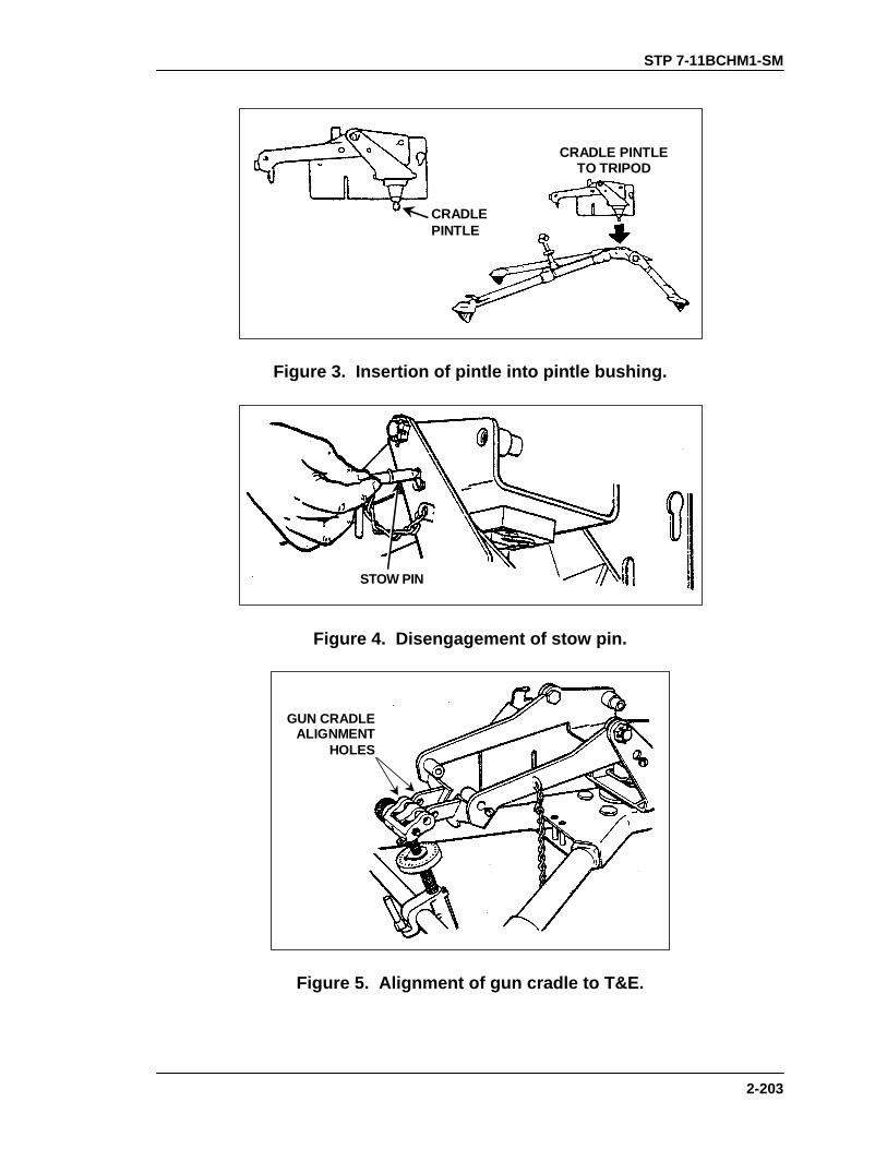
STP 7-11BCHM1-SM
2-203
CRADLEPINTLE
CRADLE PINTLETO TRIPOD
Figure 3. Insertion of pintle into pintle bushing.
STOW PIN
Figure 4. Disengagement of stow pin.
GUN CRADLEALIGNMENT
HOLES
Figure 5. Alignment of gun cradle to T&E.

STP 7-11BCHM1-SM
2-204
QUICK RELEASE PIN
Figure 6. Insertion of quick release pin.
4. Install the MK 19 on the gun mount. a. Lower the gun into the mount. Slide the gun’s front grooves onto the mounting lugs (Figure 7).
FORWARD MOUNTING LUGS
Figure 7. Sliding of gun onto mounting lugs.
b. Align the rear mounting holes of the gun with the rear holes of the gun mount (Figure 8 and Figure 9). Insert the gun mount pin from the right side and rotate it downward to locked position.

STP 7-11BCHM1-SM
2-205
ALIGN CRADLE RETAINING PINWITH HOLES
Figure 8. Alignment of sear assembly, pin holes.
CRADLE RETAINING PIN
Figure 9. Insertion of cradle retaining pin.
5. Attach the feed throat assembly (Figure 10 and Figure 11). a. Squeeze the spring-loaded pins on the feed throat assembly. b. Insert the feed throat into the forward left-hand slots of the receiver, and release the feed throat assembly pins.

STP 7-11BCHM1-SM
2-206
GRIP PINS (SQUEEZE)
Figure 10. Gripping of pins on feed throat assembly.
SNAP INTOPLACE
RECEIVER PIN HOLES
Figure 11. Insertion of feed throat assembly.
EVALUATION PREPARATION
Setup: At the test site, provide the soldier with equipment listed in task conditions. Brief Soldier: Tell the soldier to mount the MK 19 onto the M3 tripod.
EVALUATION GUIDE Performance Measures
Results
1. Set up the M3 tripod.
P F
2. Attach the T&E mechanism on the left side.
P F
3. Attach MK64 gun mount.
P F

STP 7-11BCHM1-SM
2-207
EVALUATION GUIDE Performance Measures
Results
4. Install MK 19 on gun mount.
P F
5. Attach feed throat assembly. P F
FEEDBACK
If the soldier passes all steps, score him GO. If he fails any steps, score him NO-GO, then show him what he did wrong and how to do it correctly.
REFERENCES Required Related TM 9-1010-230-10 None FM 23-27

STP 7-11BCHM1-SM
2-208
MOUNT A MK 19 MACHINE GUN ON A VEHICLE 071-030-0009
CONDITIONS Given a cleared MK 19 machine gun; an assistant gunner; an MK64 gun mount; a pintle adapter assembly; a traversing and elevation (T&E) assembly installed in the pivot arm assembly; a feed throat assembly; a mounting assembly for an ammunition can bracket; two 9/16-inch open-ended wrenches; one 3/8-inch open-ended wrench; and a vehicle equipped with either an M4 pedestal mount, an M66 ring mount, or a HMMWV armament carrier ring pedestal. STANDARDS Mount the MK 19 on a vehicle carrier correctly and without damage to equipment or injury to personnel.
TRAINING AND EVALUATION Training Information Outline
1. Install the pintle adapter. a. HMMWV armament carrier ring pedestal (Figure 1). (1) Using a 3/8-inch, open-ended wrench, loosen the HMMWV pedestal and the pintle adapter lock screws. Turn all four screws counterclockwise until the threaded ends are flush with the pedestal’s inner wall. (2) Insert the pintle adapter assembly into the HMMWV pedestal. Tighten the lock screws. Using a 3/8-inch, open-ended wrench, turn the screws clockwise to tighten them. Pull upward on the pintle adapter to make sure it is secure. (3) Remove the pintle adapter quick release pin. Press in on the pin’s quick release button, and pull the pin from the pintle adapter.
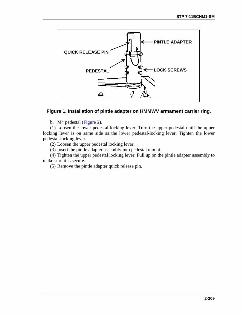
STP 7-11BCHM1-SM
2-209
LOCK SCREWS
PINTLE ADAPTER
QUICK RELEASE PIN
PEDESTAL
Figure 1. Installation of pintle adapter on HMMWV armament carrier ring.
b. M4 pedestal (Figure 2). (1) Loosen the lower pedestal-locking lever. Turn the upper pedestal until the upper locking lever is on same side as the lower pedestal-locking lever. Tighten the lower pedestal-locking lever. (2) Loosen the upper pedestal locking lever. (3) Insert the pintle adapter assembly into pedestal mount. (4) Tighten the upper pedestal locking lever. Pull up on the pintle adapter assembly to make sure it is secure. (5) Remove the pintle adapter quick release pin.

STP 7-11BCHM1-SM
2-210
TOP LOCKING LEVER
BOTTOMLOCKING
LEVER
PEDESTAL
INSTALLADAPTER
PINTLE ADAPTER
Figure 2. Installation of pintle adapter on M4 pedestal.
c. M66 ring mount (A, Figure 3). (1) Stand inside the M66 ring facing the pintle adapter hole; rotate the pintle lock handle upward. (2) Insert the pintle adapter assembly into the pedestal (B, Figure 3). (3) Rotate the pintle lock handle downward to secure the pintle adapter. Pull up on the pintle adapter to make sure it is locked in place. (4) Remove the pintle adapter quick release pin.

STP 7-11BCHM1-SM
2-211
PEDESTAL
QUICK-RELEASE PIN
PINTLEADAPTER
PINTLELOCKHANDLE
PINTLEADAPTER
HOLE
PINTLE LOCKHANDLE
A B
Figure 3. Installation of pintle adapter on M66 ring mount.
d. HMMWV Interchangeable Mount System (HIMS). Follow same procedures as for HMMWV armament carrier ring pedestal (Task Step 1a). 2. Install the MK64 gun mount (Figure 4). a. Insert the front stow pin. b. Insert the gun mount pintle into the top of the pintle adapter assembly. c. Press in on the pintle adapter quick release pin button, and insert the pin. Pull upward and twist the gun mount. It should be locked into the pintle adapter, but at the same time it should also traverse freely left and right.
PINTLE ADAPTER
GUN MOUNT PINTLE
A B
FRONTSTOW
PIN
QUICKRELEASE
PIN
Figure 4. Installation of the MK64 gun mount.
3. Attach the T&E assembly (A, Figure 5). a. Separate the middle clamp on the T&E assembly. Remove the train lock handle by turning it counterclockwise. Use a 9/16-inch, open-ended wrench to remove the hex-head screw on the other side of the clamp. b. Attach the middle clamp to the HMMWV pedestal post.

STP 7-11BCHM1-SM
2-212
(1) Assemble the middle clamp around the base of the pedestal, about 2 inches below the welded pin (B, Figure 5). Tighten the clamp by turning the train lock clockwise. Using a 9/16-inch wrench, tighten the screw on other side of clamp the same amount that you tightened the first screw. (2) Attach two support clamps. Using 9/16-inch wrenches, attach one support clamp above and one below the already installed middle clamp. Tighten each screw two turns until snug.
A BSUPPORTCLAMP
MIDDLECLAMP
MIDDLE CLAMP
Figure 5. Attachment of clamps to HMMWV armament pedestal carrier.
c. Attach the middle clamp to the M4 pedestal (A, Figure 6). (1) Assemble the middle clamp around the pedestal, about 2 inches below the welded pin (B, Figure 6). Tighten the clamp by turning the train lock clockwise. Using 9/16 wrench, equally tighten the hex head screw on other side of clamp. (2) Attach two support clamps. Using two 9/16 wrenches, attach one support clamp above and one below the already installed middle clamp. Tighten each screw two turns until snug.
A B
SUPPORTCLAMP
SUPPORTCLAMP
MIDDLECLAMP
WELDEDPIN
MIDDLE CLAMP
Figure 6. Attachment of clamps to M4 pedestal.
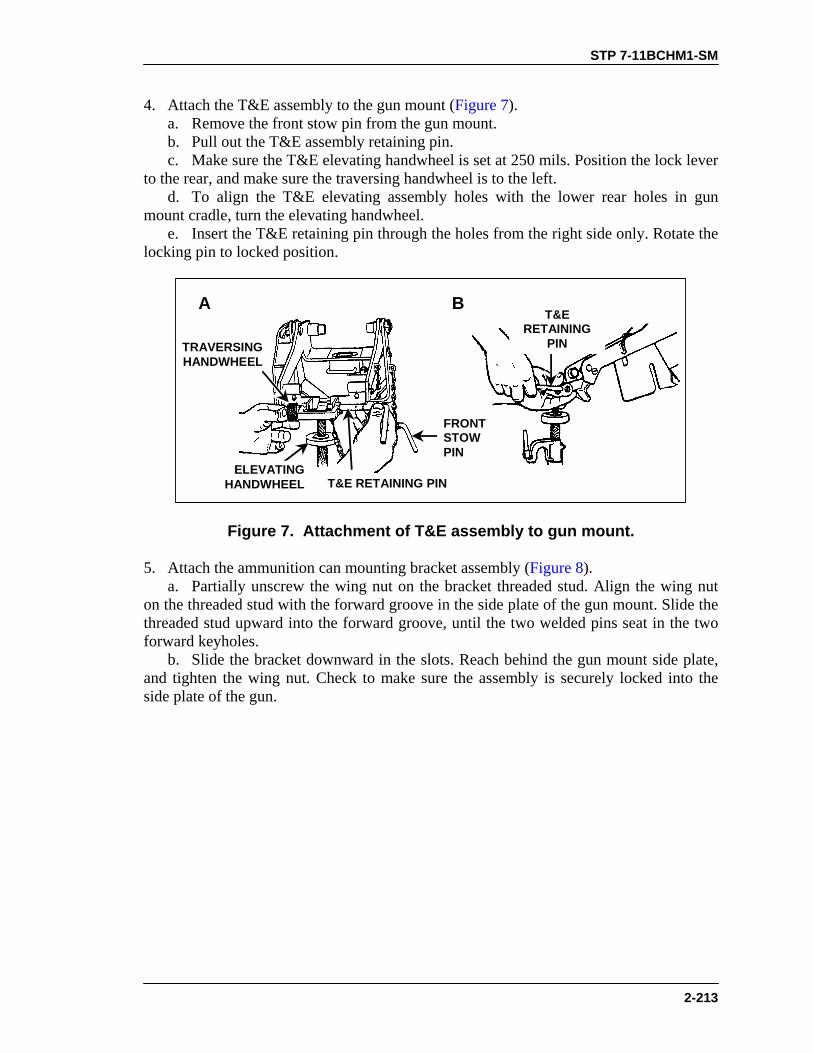
STP 7-11BCHM1-SM
2-213
4. Attach the T&E assembly to the gun mount (Figure 7). a. Remove the front stow pin from the gun mount. b. Pull out the T&E assembly retaining pin. c. Make sure the T&E elevating handwheel is set at 250 mils. Position the lock lever to the rear, and make sure the traversing handwheel is to the left. d. To align the T&E elevating assembly holes with the lower rear holes in gun mount cradle, turn the elevating handwheel. e. Insert the T&E retaining pin through the holes from the right side only. Rotate the locking pin to locked position.
A B
FRONTSTOWPIN
TRAVERSINGHANDWHEEL
ELEVATINGHANDWHEEL
T&ERETAINING
PIN
T&E RETAINING PIN
Figure 7. Attachment of T&E assembly to gun mount.
5. Attach the ammunition can mounting bracket assembly (Figure 8). a. Partially unscrew the wing nut on the bracket threaded stud. Align the wing nut on the threaded stud with the forward groove in the side plate of the gun mount. Slide the threaded stud upward into the forward groove, until the two welded pins seat in the two forward keyholes. b. Slide the bracket downward in the slots. Reach behind the gun mount side plate, and tighten the wing nut. Check to make sure the assembly is securely locked into the side plate of the gun.
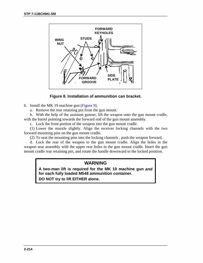
STP 7-11BCHM1-SM
2-214
STUDSWINGNUT
FORWARDKEYHOLES
FORWARDGROOVE
SIDEPLATE
Figure 8. Installation of ammunition can bracket.
6. Install the MK 19 machine gun (Figure 9). a. Remove the rear retaining pin from the gun mount. b. With the help of the assistant gunner, lift the weapon onto the gun mount cradle, with the barrel pointing towards the forward end of the gun mount assembly. c. Lock the front portion of the weapon into the gun mount cradle. (1) Lower the muzzle slightly. Align the receiver locking channels with the two forward mounting pins on the gun mount cradle. (2) To seat the mounting pins into the locking channels , push the weapon forward. d. Lock the rear of the weapon to the gun mount cradle. Align the holes in the weapon sear assembly with the upper rear holes in the gun mount cradle. Insert the gun mount cradle rear retaining pin, and rotate the handle downward to the locked position.
WARNINGA two-man lift is required for the MK 19 machine gun andfor each fully loaded M548 ammunition container.DO NOT try to lift EITHER alone.

STP 7-11BCHM1-SM
2-215
PUSHFORWARD
GUN MOUNTREAR
RETAININGPIN
SEARASSEMBLY
UPPER REARGUN MOUNT
HOLES
FORWARDMOUNTING
PINS
LOCKINGCHANNEL
GUN MOUNTREAR
RETAINING PIN
Figure 9. Installation of MK 19 on gun mount.
7. Attach the feed throat assembly (Figure 10). a. Squeeze together the spring-loaded grip pins on the feed throat assembly. b. Insert the feed throat into the forward left-hand slots of the receiver. Release the pins. Check to make sure the assembly is secure.

STP 7-11BCHM1-SM
2-216
SNAPINTO
PLACE
GRIP PINS (SQUEEZE)RECEIVER
PINHOLES
Figure 10. Attachment of the feed throat assembly.
EVALUATION PREPARATION Setup: Provide the soldier with equipment listed in conditions (If the soldier is to mount the MK 19 on a HMMWV equipped with armament carrier ring, provide only one support clamp). Brief Soldier: Tell the soldier to mount the MK 19 on the vehicle.
EVALUATION GUIDE Performance Measures
Results
1. Install the pintle adapter.
P F
2. Install the MK 64 gun mount.
P F
3. Attach the T&E assembly.
P F
4. Attach the T&E assembly to the gun mount.
P F
5. Attach the ammunition can mounting bracket assembly.
P F
6. Install the MK 19 machine gun.
P F
7. Attach the feed throat assembly. P F

STP 7-11BCHM1-SM
2-217
FEEDBACK If the soldier passes all steps, score him GO. If he fails any steps, score him NO-GO, then show him what he did wrong and how to do it correctly.
REFERENCES
Required Related FM 23-27 None TM 9-1010-231-13&P TM 9-1010-230-10
STP 7-11BCHM1-SM
2-218
PERFORM A FUNCTION CHECK ON A MK 19 MACHINE GUN
071-030-0007 CONDITIONS Given a cleared MK 19 machine gun mounted on an M3 tripod or vehicle carrier. STANDARDS Conduct an operational check of the MK 19 machine gun to make sure it is correctly assembled and functions properly.
TRAINING AND EVALUATION Training Information Outline
WARNINGBefore performing any procedure, make sure the weapon isclear of ammunition.
1. Check the functioning of the safety switch. a. With the cover closed, place safety switch on safe (S). b. Pull the bolt to rear, push charger handles to forward position, and rotate handles up. c. Press the trigger. Bolt should not go forward. d. Place the safety switch on fire (F) position. e. Press the trigger. Bolt should spring forward. f. Place the safety switch on safe (S) and leave the bolt in forward position. 2. Inspect the interior of receiver assembly for missing or damaged parts. a. Open the top cover. b. Touch the firing pin. If it is not protruding, recharge and release the bolt spring under pressure. c. Inspect the bolt face to make sure it is not worn, dirty, pitted, corroded, or in need of lubrication.
WARNINGDo not allow the top cover to slam shut from the raisedposition. Doing so could injure your hand or damagethe equipment.

STP 7-11BCHM1-SM
2-219
3. Check the feed slide assembly and feeder. a. Move the secondary drive lever back and forth. The feed slide assembly should move freely. b. Press the feed pawls to check for spring pressure. c. Inspect the link guide for roughness and galling. NOTE: Before closing the top cover, always make sure that— • The secondary drive lever is engaged with the feed slide pin. • The feed slide assembly is to the left • The bolt is forward. • Never try to force the top cover closed. Doing so could damage the
equipment. d. Close and latch the top cover. 4. If you find any deficiencies that you cannot correct, the MK 19 is unserviceable. Report the deficiencies to your supervisor.
EVALUATION PREPARATION Setup: At the test site, provide the soldier with the equipment listed in task conditions. Brief Soldier: Tell the soldier to perform a function check to determine if the MK 19 machine gun functions properly.
EVALUATION GUIDE Performance Measures
Results
1. Check functioning of safety switch.
P F
2. Inspect interior of receiver assembly for missing or damaged parts.
P F
3. Check feed slide assembly and feeder.
P F
4. Report deficiencies to supervisor. P F
FEEDBACK If the soldier passes all steps, score him GO. If he fails any steps, score him NO-GO, then show him what he did wrong and how to do it correctly.

STP 7-11BCHM1-SM
2-220
REFERENCES
Required Related TM 9-1010-230-10 None
STP 7-11BCHM1-SM
2-221
LOAD A MK 19 MACHINE GUN 071-030-0005
CONDITIONS Given a can of linked 40-mm grenade ammunition and a cleared MK 19 machine gun mounted on an M3 tripod or on a vehicle. (If firing from a vehicle, ammunition can bracket will be attached to the gun mount.) STANDARDS Load linked ammunition through feed throat into feeder so that when cover is closed, the round is straight and firmly seated against the bolt and the ammunition will feed correctly.
TRAINING AND EVALUATION Training Information Outline
1. Make sure the chamber is empty, the bolt is in the forward position, and the charger handles are in the up (lock) position. 2. Make sure the safety switch is in the safe (S) position.
WARNINGDo not let the top cover slam shut from the open position.Injury to personnel or damage to equipment could result.
3. Insert the first round. a. Open the top cover and insert the first round through the feed throat into the feeder, link opening first (Figure 1).

STP 7-11BCHM1-SM
2-222
FEMALELINK SECONDARY
PAWL
PRIMARY PAWL
Figure 1. Insertion of first round through feed throat.
b. Push or slide the round across the first set of feeder pawls, making sure the round is straight and firmly seated against the bolt (Figure 2).
Figure 2. Pushing round across feeder pawls.
c. Index the feed slide assembly to the left and close the top cover (Figure 3).

STP 7-11BCHM1-SM
2-223
SECONDARYDRIVE LEVER
Figure 3. Indexing the feed slide assembly.
4. Charge the weapon (Figure 4). a. Grasp charger handles palms down. b. Press charger handle locks and rotate charger handles down. c. Pull charger handles sharply to the rear until the bolt sears. d. Push charger handles forward and rotate them up into the lock position.

STP 7-11BCHM1-SM
2-224
PULL HANDLEREARWARD
PUSH HANDLEFORWARD
CHARGERHANDLE LOCK
Figure 4. Charging the MK 19 machine gun.
5. Load the first round. a. Place safety switch in fire (F) position and press trigger. NOTE: Bolt will move forward and load the first round on the bolt-face (half load). b. Rotate charger handles down and pull them sharply to the rear until the bolt sears. This pulls the bolt with the loaded round into position for firing (full load). c. Place safety switch in safe (S) position. d. Push the chargers forward and rotate the charger handles up into the lock position. The weapon is fully loaded. e. Leave safety switch on safe (S) position until ready to fire.

STP 7-11BCHM1-SM
2-225
WARNINGFor firing, charger handles must be FORWARD and UP.Keep your weapon pointed downrange and the line of fireclear of objects.
EVALUATION PREPARATION Setup: Provide the soldier with the equipment listed in conditions. Brief Soldier: Tell the soldier to load the MK 19 according to proper procedures.
EVALUATION GUIDE
Performance Measures
Results
1. Make sure the chamber is empty, the bolt is forward, and the charger handles are in the lock position.
P F
2. Make sure the safety switch is in the safe (S) position.
P F
3. Insert the first round. a. Open the top cover and insert the first round through the feed throat and into the feeder, link opening first. b. Push or slide the round across the first set of feeder pawls, making sure the round is straight and firmly seated against the bolt. c. Index the feed slide assembly to the left and close the top cover.
P F
4. Charge the weapon. a. Grasp the charger handles palms down. b. Press the charger handle locks and rotate charger handles down. c. Pull charger handles sharply to the rear until the bolt sears. d. Push charger handles forward and rotate them up into the lock position.
P F

STP 7-11BCHM1-SM
2-226
EVALUATION GUIDE
Performance Measures
Results
5. Load the first round. a. Place safety switch on the fire (F) position and press the trigger. b. Rotate charger handles down and pull them sharply to the rear until the bolt sears. c. Place safety switch on the safe (S) position. d. Push chargers forward and rotate the charger handles up into the locked position. e. Leave safety switch in the safe (S) position until ready to fire.
P F
FEEDBACK If the soldier passes all steps, score him GO. If he fails any steps, score him NO-GO, then show him what he did wrong and how to do it correctly.
REFERENCES Required Related FM 23-27 None TM 9-1010-230-10

STP 7-11BCHM1-SM
2-227
ZERO A MK 19 MACHINE GUN 071-030-0003
CONDITIONS Given a MK 19 machine gun, a MK 64 gun cradle, a zeroed T&E assembly mounted on a vehicle or M3 tripod, a stationary target located at a known range (400 meters) from the firing position, and linked 40-mm grenade ammunition. STANDARDS Adjust the sights on a MK 19 machine gun so that a correct sight picture will cause a fired round to impact the target at the point of aim.
TRAINING AND EVALUATION Training Information Outline
1. Prepare the sights for zeroing (Figure 1). a. Press the plunger to release the sight frame. Raise the sight frame until it locks into the “up” position. b. Loosen the retainer lock nut. Push in on the lock nut. Move the rear sight slide to the meter mark that corresponds to the distance to the target (400 meters). c. Tighten the retainer lock nut. d. Set the windage knob at the zero index line.
ELEVATING WHEEL
RETAINERLOCK NUT
PLUNGER
RANGESCALE
WINDAGEKNOB
REARSIGHTSLIDE
INDEX ONRECEIVER
ELEVATINGWHEEL
Figure 1. MK 19 machine gun sights.

STP 7-11BCHM1-SM
2-228
2. Assume a firing position. 3. Align the sights on the base of the target using the T&E mechanism. 4. Fire a single round. Spot the impact of the round. If the round is on target, fire another short burst to confirm the zero. If the round is not on target, go to Step 5. 5. Adjust for a round that is not on target. a. Elevation. (1) If the round is short, turn the knob of the elevating wheel clockwise to move the impact of the round up onto the target. (2) If the round is long, turn the knob of the elevating wheel counterclockwise to move the impact of the round down onto the target.
b. Windage. (1) If the round is to the right, adjust the sight to the left by turning the windage knob counterclockwise to move the impact of the round onto the target. (2) If the round is to the left, adjust the sight to the right by turning the windage knob clockwise to move the impact of the round onto the target. NOTE: Loosen the traversing slide lock lever to adjust the gun back onto the target.
Before you fire the next round, retighten the traversing slide lock lever. 6. Once you have zeroed the gun, align the range plate scale at the exact range of the zero and tighten it.
EVALUATION PREPARATION Setup: Evaluate this task during live firing of Table 1, Task 3, IAW FM 23-27. Provide the soldier with equipment required to fire Table 1. Brief Soldier: Tell the soldier that he will be evaluated on his ability to fire Table 1, Task 3. Brief him on the task conditions, standards, and ammunition.
EXAMPLE: If the rounds impact 10 mils short, turn the elevation knob 10mils up (clockwise). Adjust the gun back on target using the T&E before thenext round is fired. Fire a second round. If the adjustments are correct, thesecond round should be on target. If not, repeat. You may have to make boldadjustments.

STP 7-11BCHM1-SM
2-229
EVALUATION GUIDE Performance Measures
Results
1. Prepare sights for zeroing IAW Step 1.
P F
2. Assume a firing position.
P F
3. Align sights on the base of the target.
P F
4. Fire a single round and observe the impact of the round.
P F
5. Adjust elevation and windage to zero weapon.
P F
6. Align and tighten the range plate scale after zeroing. P F
FEEDBACK Score the soldier GO if all steps are passed. Score the soldier NO-GO if any steps are failed. If the soldier fails any steps, show what was done wrong and how to do it correctly.
REFERENCES Required Related FM 23-14 None FM 23-27 TM 9-1005-201-10

STP 7-11BCHM1-SM
2-230
ENGAGE TARGETS WITH A MK 19 MACHINE GUN 071-030-0004
CONDITIONS Given a zeroed MK 19 machine gun (tripod or cupola mounted), linked 40-mm grenade ammunition, and a sector of fire with engageable targets. STANDARDS Fire the MK 19 machine gun to engage targets in your assigned sector of fire. Apply correct machine gun target engagement techniques so that each target is covered with fire.
TRAINING AND EVALUATION Training Information Outline
1. Assume a suitable firing position. Based on your situation, select a firing position that will allow you to observe and engage targets yet minimize your exposure to enemy fire. a. Seated firing positions. Sit directly behind the weapon between the trail legs of the tripod. (1) Legs extended. Extend your legs under the tripod (Figure 1). (2) Legs crossed. Cross your legs and place your elbows on the inside of your thighs for support when firing the weapon (Figure 2). (3) Legs braced. Extend your legs, brace them on the trail legs of the tripod, and place your elbows on the inside of your thighs for support (Figure 1, Figure 2, and Figure 3). b. Kneeling position. Kneel and grasp the control grips with your thumbs on the trigger (Figure 4). c. Standing position for gun mounted on a vehicle pedestal (Figure 5).
Figure 1. Seated firing position, legs extended.

STP 7-11BCHM1-SM
2-231
Figure 2. Seated firing position, legs crossed.
Figure 3. Seated firing position, legs braced.
Figure 4. Kneeling position.

STP 7-11BCHM1-SM
2-232
Figure 5. Standing position for mounted gun.
2. Acquire the target using correct sight alignment. 3. Apply correct engagement technique based on target types. a. Use correct gun manipulation technique (Figure 6). (1) Fixed fire. This is fire delivered against a point target. Only one aiming point is necessary with little or no manipulation of the gun. (2) Traversing fire. This is fire distributed against a wide target requiring successive changes in direction of gun. This means using the T&E mechanism to traverse the gun left or right to distribute fire laterally. (3) Searching fire. This is fire delivered against a deep target or a linear target with depth in width by successive changes in elevation. This means using the T&E mechanism to move the muzzle of the weapon up or down to distribute fire in depth. (4) Traversing and searching fire. This is fire delivered in width and depth by successive changes in direction and elevation. It is employed against a target whose long axis is oblique to the direction of fire. (5) Swinging traverse. This is fire delivered against targets that require major changes in direction but little or no change in elevation. Loosen the traversing slide lock enough to swing the gun laterally. (6) Free gun. This is fire delivered against moving targets that must be rapidly engaged with fast changes in direction and elevation. To fire free gun, remove the T&E mechanism.

STP 7-11BCHM1-SM
2-233
TRAVERSEAND
SEARCH
SEARCHTRAVERSEFIXED
FREEGUN
SWINGINGTRAVERSE
Figure 6. Techniques of fire with respect to the MK 19.
b. Use correct application of fire to engage specific targets. (1) Point target. Engage point targets with fixed fire using a single aiming point (Figure 7).
Figure 7. Point target.
(2) Linear target. Initially aim just outside of either flank and fire. Traverse fire back and forth from flank to flank, covering the entire target area (Figure 8).

STP 7-11BCHM1-SM
2-234
Figure 8. Linear target.
(3) Linear target with depth. Initially aim at the near flank with range set to the midpoint of the target unless another portion of the target is more critical or presents a greater threat. Fire on the near flank, then traverse and search back and forth, covering the entire target (Figure 9).
Figure 9. Linear target with depth.
(4) Deep target. Initially aim at the end of the target closest to the gun, unless another portion of the target is more critical or presents a greater threat (auto rifleman). Fire and search up the far end and back again repeatedly (Figure 10).

STP 7-11BCHM1-SM
2-235
Figure 10. Deep target.
(5) Area target. Initially aim at the midpoint of the target area. Traverse and search to either flank, then traverse and search to the opposite flank (Figure 11).
Figure 11. Engagement of area targets, single gun.
4. Use observation of fire and adjusted aiming point to place effective fire on the target. a. Observation of fire. Observe the strike of the rounds in relation to the target; adjust elevation and direction needed to move the center of impact onto the target. NOTE: This does not call for use of the sights.
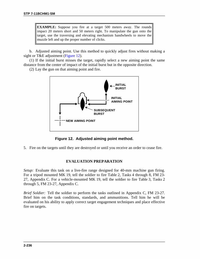
STP 7-11BCHM1-SM
2-236
b. Adjusted aiming point. Use this method to quickly adjust fires without making a sight or T&E adjustment (Figure 12). (1) If the initial burst misses the target, rapidly select a new aiming point the same distance from the center of impact of the initial burst but in the opposite direction. (2) Lay the gun on that aiming point and fire.
NEW AIMING POINT
SUBSEQUENTBURST
INITIALBURST
INITIALAIMING POINT
Figure 12. Adjusted aiming point method.
5. Fire on the targets until they are destroyed or until you receive an order to cease fire.
EVALUATION PREPARATION Setup: Evaluate this task on a live-fire range designed for 40-mm machine gun firing. For a tripod mounted MK 19, tell the soldier to fire Table 2, Tasks 4 through 8, FM 23-27, Appendix C. For a vehicle-mounted MK 19, tell the soldier to fire Table 3, Tasks 2 through 5, FM 23-27, Appendix C. Brief Soldier: Tell the soldier to perform the tasks outlined in Appendix C, FM 23-27. Brief him on the task conditions, standards, and ammunitions. Tell him he will be evaluated on his ability to apply correct target engagement techniques and place effective fire on targets.
EXAMPLE: Suppose you fire at a target 500 meters away. The roundsimpact 20 meters short and 50 meters right. To manipulate the gun onto thetarget, use the traversing and elevating mechanism handwheels to move themuzzle left and up the proper number of clicks.

STP 7-11BCHM1-SM
2-237
EVALUATION GUIDE Performance Measures
Results
1. Assume a suitable firing position.
P F
2. Apply correct engagement technique based on target type. a. Use correct gun manipulation technique. b. Use correct application of fire to engage specific targets.
P F
3. Place effective fire on targets (score a minimum of 84 points).
P F
4. Use correct application of fire to engage specific targets.
P F
5. Use observation of fire and adjust aiming point to place effective fire on the target.
P F
FEEDBACK If the soldier passes all steps, score him GO. If he fails any steps, score him NO-GO, then show him what he did wrong and how to do it correctly.
REFERENCES Required Related FM 23-27 None

STP 7-11BCHM1-SM
2-238
CORRECT MALFUNCTIONS OF A MK 19 MACHINE GUN 071-030-0008
CONDITIONS Given a loaded MK 19 machine gun mounted on an M3 tripod or vehicle, linked 40-mm grenade ammunition, a caliber .50 cleaning rod, a bore obstruction device (BOD), an assistant gunner, rifle bore cleaner (RBC), lubricating oils (LSA and either LSAT or LAW), grease (GMD), cleaning solvent (PD680), wiping rags, cloth (abrasive crocus), cleaning rod assembly, small arms cleaning brushes, and one of the following situations: the weapon has failed to fire; the weapon is firing sluggishly; or the weapon has uncontrolled fire (continues to fire after the trigger is released). STANDARDS Take immediate action on a MK 19 machine gun that has failed to fire without identifying the cause of the malfunction. If immediate action is unsuccessful, perform remedial action to identify the cause of the malfunction. Take immediate action to secure a runaway MK 19 machine gun; then take remedial action to eliminate the malfunction. Take corrective action for a MK 19 machine gun that is firing sluggishly.
TRAINING AND EVALUATION Training Information Outline
1. Apply immediate action when the weapon fails to fire (during peacetime and during training). NOTE: Clear all nonessential personnel away from the gun position.
STP 7-11BCHM1-SM
2-239
DANGER1. IF ANYTHING UNUSUAL OCCURS DURING FIRING
(INCLUDING SHORT RECOIL, OUT OF BATTERY,EXCESS SMOKE, FLASH, LOUD OR MUFFLEDREPORT, MALFUNCTION, OR STOPPAGE)IMMEDIATELY INSPECT THE WEAPON. CLEAR THEWEAPON. CHECK THE BARREL FOR OBSTRUCTION.CHECK THE FEEDER, BOLT FACE, AND RECEIVERFOR DAMAGE OR UNUSUAL DEBRIS. DO NOT TRYTO CLEAR AN OBSTRUCTED BORE. TO GETASSISTANCE, FOLLOW THE INSTRUCTIONS IN THELOCAL OR UNIT SOP. CONTINUED FIRING MAYCAUSE DEATH OR INJURY.
2. DO NOT RELINK OR FIRE AMMUNITION THAT HASBEEN CYCLED THROUGH THE WEAPON.
WARNING1. Clear all nonessential personnel away from the gun
position.2. If, when you fire a round, you--
• Hear a muffled sound• See excess smoke coming out of the chamber area• See excess debris, gas, or both coming from below
the gunDO NOT perform immediate action.DO notify your supervisor.
a. Keep the weapon pointed at the target. b. Pull the bolt to the rear to charge the weapon and have the assistant gunner catch the live round as it is ejected. c. If the weapon will not charge, stop immediate action and apply remedial action to clear a jammed bolt (Step 2b). d. Push the charging handles forward and up. e. Place the safety switch in the safe (S) position. f. Check for bore obstruction. (1) Make sure the safety switch is on safe (S).
STP 7-11BCHM1-SM
2-240
WARNING1. DO NOT let the bolt go forward--this could cause a
round to fire accidentally.2. DO NOT insert your hands into the receiver with the bolt
locked to the rear on sear. If you do so, you could suffera severe injury.
3. DO make sure the safe/fire switch is in the safe(S) position.
(2) Lower the charging handles, maintain your grip, and apply back pressure to the bolt. (3) Have the assistant gunner open the top cover and check the bolt face for a live round. (4) If a live round, spent case, or debris is present-- (a) Have the assistant gunner remove the catch bag and be prepared to catch live any live ammunition that falls from the bottom of the weapon. (b) Charge the bolt completely until the bolt clicks (locks) to the rear. Return the handles to the forward position, handles down. (c) If a round is still present, have the assistant gunner clear it from the bolt face by inserting a cleaning rod through the slot in the charger handle assembly and catching the round. (d) Have the assistant gunner place the bore obstruction device (BOD) into the chamber end of the barrel (weighted end first). (e) Snake the BOD into the barrel. (f) If the cable stops feeding, pull it back and push it forward again. (g) If you cannot push the cable forward any farther, the bore is obstructed. STOP. Notify your supervisor at once
WARNINGIf you find that the bore of the weapon is obstructed, notifyyour supervisor and follow your unit SOP.Never try to remove an obstructing round from the bore.Only trained and qualified personnel should do so.DO NOT transport a weapon with a projectile lodged inthe bore.
(5) If you are able to insert the BOD cable through the barrel so that you see the weighted end of the cable protruding from the flash suppressor, then the barrel is clear. (6) Move the safety switch to the fire (F) position and try to fire. (7) If the weapon does not fire, put the safety switch on safe (S) and wait 10 seconds.
STP 7-11BCHM1-SM
2-241
(8) Pull the bolt to the rear. Have the assistant gunner catch the live round as it ejects. (9) Notify your supervisor. 2. Apply immediate action during combat. a. Press the charger handle locks, and rotate the charger handles down. b. Pull the charger handles to the rear until the bolt sears. c. Push the charger handles forward and rotate them up. d. Relay the gun and fire. e. If the gun fails to fire, apply remedial action.
WARNINGDo not use combat misfire procedures during peacetime ortraining. Serious injury can result if you do not observeprecautions.
NOTE: Both charger handles must be forward and up for firing. If either handle is
down, the gun will not fire. 3. Apply remedial action to correct malfunctions. a. Correct sluggish operation of a MK 19 machine gun. (1) Clean weapon and perform operator-level maintenance. Refer to task 071-030-0001, Maintain a MK 19 Machine Gun. (2) Check recoil springs for weakness and bent guide rods. (3) If you find defects that are not correctable, notify your supervisor.
WARNINGBe sure bolt is forward before removing backplate pinassembly. Otherwise, serious injury could result!
b. Clear a jammed bolt (weapon will not charge).
DANGERPERFORM THESE PROCEDURES IN SEQUENCE.OTHERWISE, THE BOLT COULD SPRING FORWARDSUDDENLY AND FIRE A ROUND, CAUSING INJURYOR DEATH.
NOTE: Clear all non-essential personnel away from the gun position. (1) Place the safety switch on the safe (S) position. (2) Press the charger handle locks, and rotate the charger handles down.
STP 7-11BCHM1-SM
2-242
(3) Pull the charger handles to the rear as far as possible. Maintain rearward pressure on them, and have the assistant gunner lift the top cover.
DANGERDO NOT ALLOW THE BOLT TO SLAM FORWARD WHILEYOU ARE OPENING THE TOP COVER.IF THE BOLT WERE TO SLAM FORWARD WHILE YOU AREOPENING THE TOP COVER, THE WEAPON COULD FIRE ALIVE ROUND, CAUSING INJURY OR DEATH.
(4) Pull the charger handles to the rear until the bolt clicks (locks); make sure the bolt stays to the rear when you release the charger handles. (5) Insert the cleaning rod section through the slot in the side of the receiver. Prepare to catch the ejected round. (6) Raise the cleaning rod to force the live round down. Catch the live round as it ejects. (7) Remove the ammunition belt from feeder. (8) Reposition the ammunition belt in the feeder. (9) Place the safety switch on fire (F) position. (10) Ride the bolt forward by grasping one charging handle and depressing the trigger. (11) Make sure the feed slide assembly is to the left. (12) Make sure the secondary drive lever is engaged with the feed slide pin. If not, engage the forked end with the feed slide pin. (13) Close the top cover gently. (14) Charge the weapon and try to fire. (15) If the bolt jams again, repeat (1) through (7). Then, place the safety switch on the safe (S) position, and notify your supervisor. c. Apply corrective action for uncontrolled fire (runaway gun).
WARNINGNever try to twist the belt with your hands. This could resultin serious injury to personnel.
(1) Keep the gun pointed on target. (2) Lower one charging handle to make the gun stop firing. (3) Place the safety switch on safe (S) position. (4) Clear the weapon and report its condition to your supervisor.

STP 7-11BCHM1-SM
2-243
EVALUATION PREPARATION Setup: Provide soldier with the equipment and personnel listed in conditions. Brief Soldier: Tell the soldier to take the correct action for each situation listed in standards, one situation at the time. If it is unclear what actions the soldier is performing, have the soldier describe the action.
EVALUATION GUIDE Performance Measures
Results
1. Apply immediate action when the weapon fails to fire. a. Peacetime and training. b. Combat only.
P F
2. Apply remedial action to correct malfunction. a. Correct the sluggish operation of a MK 19 machine gun. b. Clear a jammed bolt (weapon will not charge). c. Apply corrective action for uncontrolled fire (runaway gun).
P F
FEEDBACK If the soldier passes all steps, score him GO. If he fails any steps, score him NO-GO, then show him what he did wrong and how to do it correctly.
REFERENCES Required Related FM 23-27 None TM 9-1010-230-10
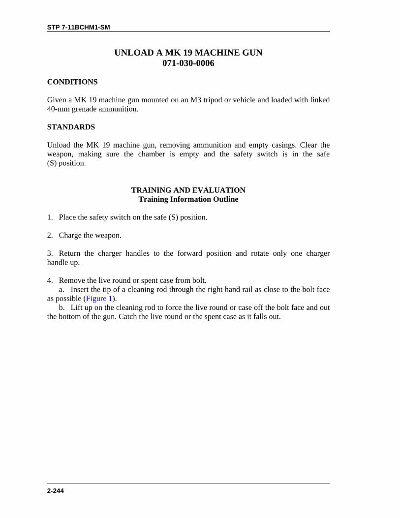
STP 7-11BCHM1-SM
2-244
UNLOAD A MK 19 MACHINE GUN 071-030-0006
CONDITIONS Given a MK 19 machine gun mounted on an M3 tripod or vehicle and loaded with linked 40-mm grenade ammunition. STANDARDS Unload the MK 19 machine gun, removing ammunition and empty casings. Clear the weapon, making sure the chamber is empty and the safety switch is in the safe (S) position.
TRAINING AND EVALUATION Training Information Outline
1. Place the safety switch on the safe (S) position. 2. Charge the weapon. 3. Return the charger handles to the forward position and rotate only one charger handle up. 4. Remove the live round or spent case from bolt. a. Insert the tip of a cleaning rod through the right hand rail as close to the bolt face as possible (Figure 1). b. Lift up on the cleaning rod to force the live round or case off the bolt face and out the bottom of the gun. Catch the live round or the spent case as it falls out.
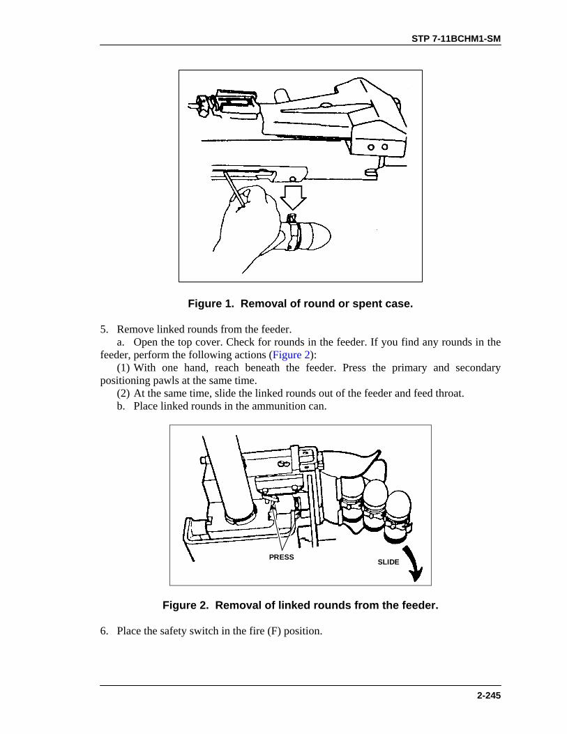
STP 7-11BCHM1-SM
2-245
Figure 1. Removal of round or spent case.
5. Remove linked rounds from the feeder. a. Open the top cover. Check for rounds in the feeder. If you find any rounds in the feeder, perform the following actions (Figure 2): (1) With one hand, reach beneath the feeder. Press the primary and secondary positioning pawls at the same time. (2) At the same time, slide the linked rounds out of the feeder and feed throat. b. Place linked rounds in the ammunition can.
SLIDEPRESS
Figure 2. Removal of linked rounds from the feeder.
6. Place the safety switch in the fire (F) position.
STP 7-11BCHM1-SM
2-246
7. Ride the bolt forward. a. Hold one charger handle to the rear. b. Press the trigger to release the bolt; ride the bolt forward. c. Make sure both charging handles are forward and in the up position. 8. Place the safety switch in the safe (S) position. 9. Index the feed slide assembly to the left. 10. Close and latch the top cover.
EVALUATION PREPARATION Setup: Provide the soldier with the equipment listed in the task conditions statement. Brief Soldier: Tell the soldier to load the MK 19 according to the task steps.
EVALUATION GUIDE Performance Measures
Results
1. Place the safety switch on safe (S) position.
P F
2. Charge the weapon.
P F
3. Return the charger handles to the forward position, and rotate only one charger handle up.
P F
4. Remove the live round or spent case from bolt. a. Insert the tip of a cleaning rod through the right-hand rail as close to the bolt face as possible. b. Raise up on the cleaning rod to force the live round or case off the bolt face and out the bottom of the gun. Catch the live round or the spentcase as it falls out.
P F
5. Remove any linked rounds from the feeder. a. Open the top cover. Check for rounds in the feeder. If you findrounds in the feeder, then perform the following actions: (1) With one hand, reach beneath the feeder, and press the primaryand secondary positioning pawls at the same time. (2) At the same time, slide the linked rounds out of the feeder andfeed throat. b. Place linked rounds in the ammunition can.
P F
STP 7-11BCHM1-SM
2-247
EVALUATION GUIDE Performance Measures
Results
6. Place the safety switch on fire (F) position.
P F
7. Ride the bolt forward. a. Hold one charger handle to the rear. b. Press the trigger to release the bolt, and ride the bolt forward. c. Make sure both charging handles are forward and in theup position.
P F
8. Place the safety switch on safe (S) position.
P F
9. Index the feed slide assembly to the left.
P F
10. Close and latch the top cover. P F
FEEDBACK If the soldier passes all steps, score him GO. If he fails any steps, score him NO-GO, then show him what he did wrong and how to do it correctly.
REFERENCES Required Related FM 23-27 None TM 9-1010-230-10

STP 7-11BCHM1-SM
2-248
DISMOUNT A MK 19 MACHINE GUN FROM AN M3 TRIPOD 071-030-0012
CONDITIONS Given a cleared MK 19 machine gun mounted on an M3 tripod, and an assistant gunner. STANDARDS Remove the MK 19 from the M3 tripod without damage to equipment or injury to personnel.
TRAINING AND EVALUATION Training Information Outline
WARNING1. A two-man lift is required for the MK 19 machine gun
and each fully loaded M548 ammunition container. DONOT try to lift either by yourself.
2. Before performing any procedure, make sure theweapon is clear of all ammunition.
1. Check to make sure the weapon is clear. 2. Squeeze the spring-loaded pins on the feed throat assembly, and remove the feed throat assembly. 3. Remove the gun mount retaining pin. 4. Lift up and pull the gun rearward until it is free of the mounting lugs. Then, with the help of the assistant gunner, lift the gun from the gun mount. 5. Remove the T&E mechanism. 6. Reach under the tripod head (right side) and lift the pintle lock. Remove the gun mount from the tripod.
WARNINGWhen extending or collapsing the M3 tripod, grasp the feeton the rear legs. The sliding sleeve on the right rear leg cancause injury to personnel.

STP 7-11BCHM1-SM
2-249
7. Adjust the tripod legs to their shortest length. Collapse the tripod for carrying or stowing.
EVALUATION PREPARATION Setup: At the test site, provide the soldier with the equipment listed in the task conditions statement. Brief Soldier: Tell the soldier that he must dismount the MK 19 from the M3 tripod.
EVALUATION GUIDE Performance Measures
Results
1. Check to make sure weapon is clear.
P F
2. Remove feed throat assembly.
P F
3. Remove gun from gun mount.
P F
4. Remove T&E mechanism.
P F
5. Remove the gun mount from the tripod.
P F
6. Prepare the tripod for carrying or stowing. P F
FEEDBACK If the soldier passes all steps, score him GO. If he fails any steps, score him NO-GO, then show him what he did wrong and how to do it correctly.
REFERENCES Required Related FM 23-27 None TM 9-1010-230-10

STP 7-11BCHM1-SM
2-250
DISMOUNT A MK 19 MACHINE GUN FROM A VEHICLE 071-030-0010
CONDITIONS Given an assistant gunner, a cleared MK 19 machine gun mounted on a vehicle equipped with M4 pedestal mount, M66 ring mount, or HMMWV armament carrier ring and pedestal. STANDARDS Remove MK 19 machine gun and components from the vehicle carrier without damage to equipment or injury to personnel.
TRAINING AND EVALUATION Training Information Outline
WARNINGA two-man lift is required for the MK 19 machine gun andeach fully loaded M548 ammunition container.DO NOT try to carry either the weapon or a fully loadedammunition container by yourself.
1. Remove the MK 19 from a vehicle equipped with the M4 pedestal. a. Remove the feed throat assembly. b. Remove the rear retaining pin from the gun mount cradle. c. Remove the front stow pin from the gun mount cradle. d. Lift the MK 19 from the M4 pedestal. e. Remove the ammunition container bracket. f. Remove the support clamps from the M4 pedestal. g. Remove the quick release pin from the pintle adapter. h. Remove the gun mount from the M4 pedestal. i. Loosen the upper locking lever on the M4 pedestal. j. Lift the pintle adapter from the M4 pedestal. k. Tighten the upper locking lever on the M4 pedestal. 2. Remove the MK 19 from the HMMWV armament carrier ring and pedestal. a. Perform Steps 1a through 1h for the M4 pedestal. b. Loosen the pedestal bolts, and remove the pintle adapter. c. Tighten the pedestal bolts.

STP 7-11BCHM1-SM
2-251
3. Remove the MK 19 from a vehicle equipped with an M66 ring mount. a. Perform Steps 1a through 1h for the M4 pedestal. b. Rotate the pintle lock handle to the unlocked position. c. Remove the pintle adapter.
EVALUATION PREPARATION Setup: Provide the soldier with equipment and personnel listed in conditions. Brief Soldier: Tell the soldier to correctly dismount the MK 19 from the vehicle without damage to equipment or injury to personnel.
EVALUATION GUIDE
Performance Measures
Results
1. Remove MK 19 from vehicle equipped with M4 pedestal.
P F
2. Remove MK 19 from the HMMWV armament carrier ringand pedestal.
P F
3. Remove MK 19 from vehicle equipped with M66 ring mount. P F
FEEDBACK If the soldier passes all steps, score him GO. If he fails any steps, score him NO-GO, then show him what he did wrong and how to do it correctly.
REFERENCES
Required Related FM 23-27 None TM 9-1010-231-13&P

STP 7-11BCHM1-SM-TG
3-252
M203 GRENADE LAUNCHER
PERFORM A FUNCTION CHECK ON AN M203 GRENADE LAUNCHER
071-311-2126 CONDITIONS Given an M203 grenade launcher. STANDARDS Perform a check to determine if the M203 grenade launcher is functioning properly.
TRAINING AND EVALUATION Training Information Outline
WARNINGEnsure weapon is unloaded.
1. Check to ensure weapon is clear. 2. Check operation of sear. a. Cock the launcher and squeeze the trigger; the firing pin should release. b. Hold the trigger to the rear and cock the launcher. c. Release the trigger and then squeeze the trigger; the firing pin should release.
WARNINGThe launcher could fire without squeezing the trigger if thesear does not function properly.
3. Check safety. a. Cock the launcher. b. Place the safety on SAFE and pull the trigger; the firing pin should not release. c. Place the safety on FIRE and pull the trigger; the firing pin should release. 4. Move the barrel forward and back and check to ensure the stop and barrel latch function correctly. 5. Turn in the weapon to the unit armorer if it does not function correctly.

STP 7-11BCHM1-SM-TG
3-253
EVALUATION PREPARATION Setup: Provide the equipment in the conditions statement. Brief Soldier: Tell the soldier to perform a function check on the M203 grenade launcher. Inform the soldier that he must notify the evaluator if the M203 does not function correctly.
EVALUATION GUIDE Performance Measures
Results
1. Check operation of sear.
P F
2. Check safety.
P F
3. Check the barrel stop and barrel latch.
P F
4. Turn in malfunctioning weapon to the unit armorer. P F
FEEDBACK If the soldier passes all steps, score him GO. If he fails any steps, score him NO-GO, then show him what he did wrong and how to do it correctly.
REFERENCES
Required Related TM 9-1010-221-10 None

STP 7-11BCHM1-SM
1-254
MAINTAIN AN M203 GRENADE LAUNCHER 071-311-2125
CONDITIONS Given an M203 grenade launcher; cleaner, lubricant, preservative (CLP); thong; bore brush; and clean rags. STANDARDS Clear the M203 grenade launcher; disassemble the M203; clean and lubricate the M203; inspect the M203 before assembly; assemble the M203; and perform a function check on the M203.
TRAINING AND EVALUATION Training Information Outline
1. Clear the M203 grenade launcher. 2. Disassemble the M203 (Figure 1).
BARREL STOP(INSIDE
HANDGUARD)
SAFETYTRIGGERBARREL
RECEIVER
BARRELLATCH
LEAFSIGHT HANDGUARD
SERIALNUMBER
QUADRANTSIGHT
Figure 1. Components of the M203 grenade launcher.
WARNINGBefore disassembling the weapon, clear the rifle andgrenade launcher.
a. Remove the quadrant sight (if used) by loosening the knurled screw on the right side (Figure 2).

STP 7-11H14-SM-TG
3-255
Figure 2. Removing quadrant sight.
b. Pull back the slip ring. Lift up on the handguard and pull it to the rear to remove (Figure 3).
SLIP RING
REMOVE
Figure 3. Removing handguards.
c. Press the barrel latch and move the barrel forward to the barrel stop (Figure 4).
Figure 4. Unlocking and opening the M203 barrel.
d. Press the barrel stop to release the barrel from the receiver and remove the barrel (Figure 5).

STP 7-11BCHM1-SM
1-256
BARREL STOP
Figure 5. Removing the M203 barrel.
NOTE: Further disassembly may only be performed by the armorer. 3. Clean and lubricate the M203. a. Bore. Attach a clean, dry rag to the thong and thoroughly moisten the rag with CLP. Pull the rag through the bore several times. Attach the bore brush to the thong, pull it through the bore several times, and follow this with more rags, moistened with CLP, if needed (Figure 6). Pull dry rags through the bore and inspect each rag as it is removed. The bore is clean when a dry rag is removed unfouled. Pull a rag lightly moistened with CLP through the bore to leave a light coat of lubricant inside the barrel.
BOREBRUSH
Figure 6. Cleaning the M203 barrel.
b. Breech insert. Clean the face of the breech insert retainer with a patch and CLP. Remove the CLP cleaner with dry rags, then lubricate the breech with a light coat of CLP. c. All other parts. Use a brush and dry rags to clean all other parts and surfaces. Apply a light coat of CLP to the exterior of the launcher after cleaning. d. Safety mechanism. Clean the safety mechanism properly with CLP. Lubricate the safety with CLP. NOTE: For cleaning the rifle portion of the launcher, refer to Task 071-311-2025,
Maintain an M16A1 or M16A2 Rifle. 4. Inspect the M203 before assembly.

STP 7-11H14-SM-TG
3-257
a. Check handguard for cracks, dents, or distortion that prevent its firm attachment to the rifle. b. Check leaf sight for bent or damaged parts and for rust or corrosion. c. Check leaf sight for legibility of marking. d. Check barrel for cracks and general condition. Inspect all parts for wear and damage. e. Check for burrs, scratches, nicks, or other damage. 5. Assemble the M203. a. Press the barrel stop. Slide the barrel into the receiver (Figure 7).
BARRELSTOP
Figure 7. Installing the M203 barrel.
b. Move the barrel rearward to close (Figure 8).
Figure 8. Locking the M203 barrel.
c. Install the handguard and secure with the slip ring (Figure 9).
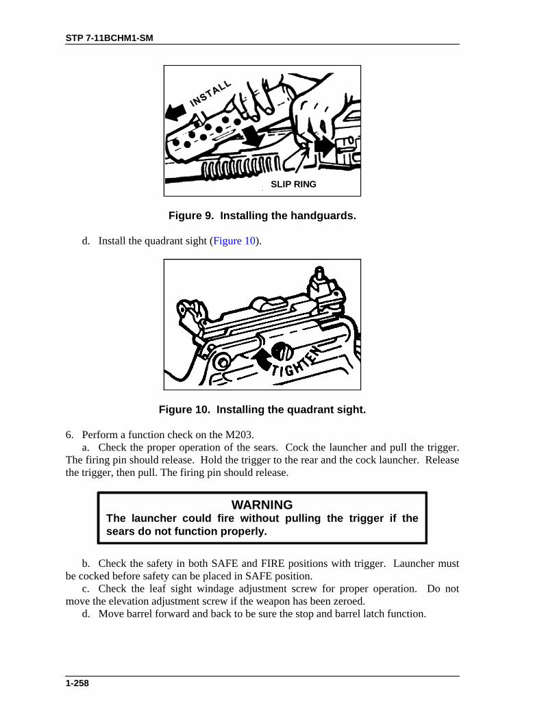
STP 7-11BCHM1-SM
1-258
SLIP RING
Figure 9. Installing the handguards.
d. Install the quadrant sight (Figure 10).
Figure 10. Installing the quadrant sight.
6. Perform a function check on the M203. a. Check the proper operation of the sears. Cock the launcher and pull the trigger. The firing pin should release. Hold the trigger to the rear and the cock launcher. Release the trigger, then pull. The firing pin should release.
WARNINGThe launcher could fire without pulling the trigger if thesears do not function properly.
b. Check the safety in both SAFE and FIRE positions with trigger. Launcher must be cocked before safety can be placed in SAFE position. c. Check the leaf sight windage adjustment screw for proper operation. Do not move the elevation adjustment screw if the weapon has been zeroed. d. Move barrel forward and back to be sure the stop and barrel latch function.
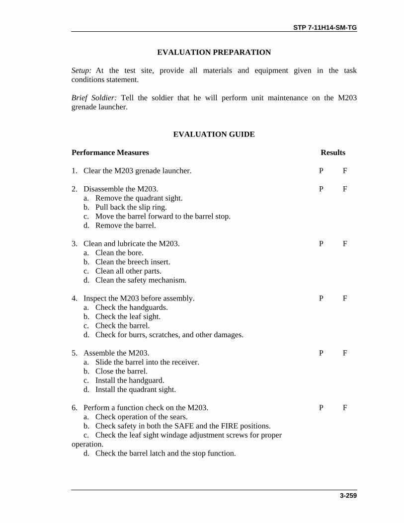
STP 7-11H14-SM-TG
3-259
EVALUATION PREPARATION Setup: At the test site, provide all materials and equipment given in the task conditions statement. Brief Soldier: Tell the soldier that he will perform unit maintenance on the M203 grenade launcher.
EVALUATION GUIDE Performance Measures
Results
1. Clear the M203 grenade launcher.
P F
2. Disassemble the M203. a. Remove the quadrant sight.
P F
b. Pull back the slip ring. c. Move the barrel forward to the barrel stop. d. Remove the barrel.
3. Clean and lubricate the M203. a. Clean the bore.
P F
b. Clean the breech insert. c. Clean all other parts. d. Clean the safety mechanism.
4. Inspect the M203 before assembly. a. Check the handguards.
P F
b. Check the leaf sight. c. Check the barrel. d. Check for burrs, scratches, and other damages.
5. Assemble the M203. a. Slide the barrel into the receiver.
P F
b. Close the barrel. c. Install the handguard. d. Install the quadrant sight.
6. Perform a function check on the M203. a. Check operation of the sears.
P F
b. Check safety in both the SAFE and the FIRE positions. c. Check the leaf sight windage adjustment screws for proper operation. d. Check the barrel latch and the stop function.

STP 7-11BCHM1-SM
1-260
FEEDBACK If the soldier passes all steps, score him GO. If he fails any steps, score him NO-GO, then show him what he did wrong and how to do it correctly.
REFERENCES Required Related None FM 23-31 TM 9-1010-221-10

STP 7-11BCHM1-SM
2-261
CONSTRUCT FIELD-EXPEDIENT FIRING AIDS FOR AN M203 GRENADE LAUNCHER
071-032-0006 CONDITIONS As a member of a rifle squad in a defensive position during daylight, given an M203 grenade launcher, M203 ammunition, sticks or rocks, boards or logs available in the area, instructions on the individual’s preplanned sectors of fire for use during limited visibility, and left and right limits. STANDARDS Construct and place out aiming and firing stakes for use during limited visibility. Ensure the stakes mark targets in the sector of fire (to include likely avenues of enemy approach and enemy assault positions) and that they also mark dead spaces.
TRAINING AND EVALUATION Training Information Outline
1. Within the sector of fire, locate possible targets, dead space, likely avenues of enemy approach, and likely enemy assault positions. 2. Estimate the range to the located targets by one of the following methods: a. Pacing. (See Task 071-329-1006, Navigate from one Point on the Ground to Another Point While Dismounted, STP 21-24-SMCT). b. Map Distance. (See Task 071-329-1008, Measure Distance on a Map, STP 21-1-SMCT). c. Naked Eye. (See Task 071-326-0512, Estimate Range, STP 21-1-SMCT). 3. Place the estimated range to target on the quadrant sight. 4. Place the launcher on the ground with the muzzle pointing at the target and the butt plate at the fighting position. 5. Scoop out a small amount of earth, creating a small hole where the butt plate touches the ground. 6. Place the toe of the butt plate into the hole. 7. Get into the fighting position, raise the muzzle of the launcher, look through the quadrant sight, and adjust the elevation of the muzzle until the correct sight picture is observed.
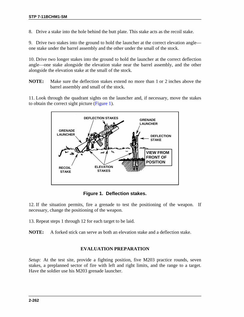
STP 7-11BCHM1-SM
2-262
8. Drive a stake into the hole behind the butt plate. This stake acts as the recoil stake. 9. Drive two stakes into the ground to hold the launcher at the correct elevation angle—one stake under the barrel assembly and the other under the small of the stock. 10. Drive two longer stakes into the ground to hold the launcher at the correct deflection angle—one stake alongside the elevation stake near the barrel assembly, and the other alongside the elevation stake at the small of the stock. NOTE: Make sure the deflection stakes extend no more than 1 or 2 inches above the
barrel assembly and small of the stock. 11. Look through the quadrant sights on the launcher and, if necessary, move the stakes to obtain the correct sight picture (Figure 1).
GRENADELAUNCHER DEFLECTION
STAKE
VIEW FROMFRONT OFPOSITION
GRENADELAUNCHER
RECOILSTAKE
DEFLECTION STAKES
ELEVATIONSTAKES
Figure 1. Deflection stakes.
12. If the situation permits, fire a grenade to test the positioning of the weapon. If necessary, change the positioning of the weapon. 13. Repeat steps 1 through 12 for each target to be laid. NOTE: A forked stick can serve as both an elevation stake and a deflection stake.
EVALUATION PREPARATION Setup: At the test site, provide a fighting position, five M203 practice rounds, seven stakes, a preplanned sector of fire with left and right limits, and the range to a target. Have the soldier use his M203 grenade launcher.

STP 7-11BCHM1-SM
2-263
Brief Soldier: Tell the soldier to emplace firing stakes with the correct elevation and deflection to cause rounds to impact on a target when he fires the M203.
EVALUATION GUIDE Performance Measures
Results
1. Place the correct range on the quadrant sight.
P F
2. Place the stakes in the correct position. a. Recoil stake. b. Elevation stake. c. Deflection stake.
P F
3. Place the quadrant sight on the target. P F
FEEDBACK If the soldier passes all steps, score him GO. If he fails any steps, score him NO-GO, then show him what he did wrong and how to do it correctly.
REFERENCES Required Related None FM 7-7 FM 7-8 FM 7-7J

STP 7-11BCHM1-SM
2-264
ZERO AN M203 GRENADE LAUNCHER 071-311-2103
CONDITIONS Given an unzeroed M203 grenade launcher and five rounds of HE or TP ammunition (for each type of sight). STANDARDS Obtain an elevation and windage sight setting (on both leaf and quadrant sights) that will allow two consecutive rounds to hit within 5 meters of the point of aim at a distance of 200 meters.
TRAINING AND EVALUATION Training Information Outline
WARNING1. Do not fire this launcher until you have read this task.2. Only use ammunition manufactured IAW United States
specifications.3. Keep the safety on until ready to fire the weapon.4. Always keep the weapon pointed downrange.5. Do not use a range of less than 100 meters to zero.
1. Select a target at 200 meters and fire a round. If the round does not fall within 5 meters of the target, zeroing procedures are called for. Make sight adjustments for more or less elevation. Make windage adjustments for each firing. After each round is fired, make the necessary adjustments until two consecutive rounds land within 5 meters of the aiming point (Figure 1).
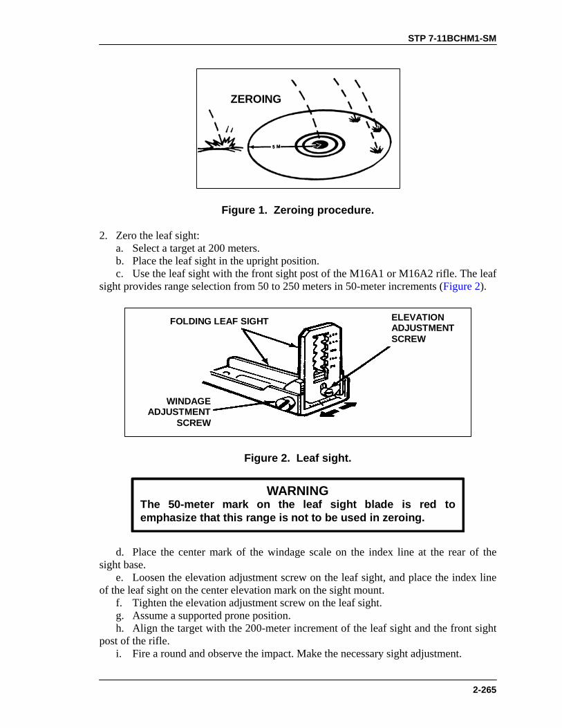
STP 7-11BCHM1-SM
2-265
ZEROING
Figure 1. Zeroing procedure.
2. Zero the leaf sight: a. Select a target at 200 meters. b. Place the leaf sight in the upright position. c. Use the leaf sight with the front sight post of the M16A1 or M16A2 rifle. The leaf sight provides range selection from 50 to 250 meters in 50-meter increments (Figure 2).
ELEVATIONADJUSTMENTSCREW
FOLDING LEAF SIGHT
WINDAGEADJUSTMENT
SCREW
Figure 2. Leaf sight.
WARNINGThe 50-meter mark on the leaf sight blade is red toemphasize that this range is not to be used in zeroing.
d. Place the center mark of the windage scale on the index line at the rear of the sight base. e. Loosen the elevation adjustment screw on the leaf sight, and place the index line of the leaf sight on the center elevation mark on the sight mount. f. Tighten the elevation adjustment screw on the leaf sight. g. Assume a supported prone position. h. Align the target with the 200-meter increment of the leaf sight and the front sight post of the rifle. i. Fire a round and observe the impact. Make the necessary sight adjustment.

STP 7-11BCHM1-SM
2-266
(1) Turn the sight windage screw clockwise to move the strike of the round to the left. Turn the windage screw counterclockwise to move the strike to the right. One increment either way equals 1 1/2 meters at a range of 200 meters. (2) Raise the leaf sight to increase range; lower it to decrease range. One increment equals 10 meters at a range of 200 meters. j. Fire one or more rounds. Make necessary adjustments after each round until a round has landed within 5 meters of the target. k. Fire a confirming round. 3. Zero the quadrant sight (Figure 3): a. Select a target at 200 meters. b. Ensure that the sight is correctly mounted on the carrying handle of the rifle.
LATCHRETAINER(press down)
FOLDOUT
RANGEQUADRANT
FOLDOUT
FRONTSITE
POST
REARAPERTURE
Figure 3. Quadrant sight.
NOTE: The quadrant sight attaches to the rifle handle and provides range selection from 50 to 400 meters in 25-meter increments. Elevation adjustment: one notch equals 5 meters at 200 meters. The rear aperture slides in or out for windage correction when the retainer is depressed. A vertical line denotes the center. One notch equals 1 1/2 meters at a 200-meter range. Turn the front sight post right for less elevation and left for more elevation. Slide the rear aperture in to move the strike of the projectile to the right; slide it out to move the strike to the left.
c. Move the front sight post and the rear sight aperture from closed to open. (1) Depress the rear sight retainer. Slide the rear sight aperture left or right to align the wide index line of the rear sight aperture with the edge of the sight aperture arm. (2) Move the front sight post to its highest position and then back 2 1/2 turns. d. Move the sight latch rearward. Reposition the quadrant sight arm to zeroing range (200 meters). e. Take a supported prone position. f. Align the target with the front and rear sights, using the correct sighting and aiming procedures. g. Fire a round, observe the impact, and make the necessary sight adjustment.

STP 7-11BCHM1-SM
2-267
(1) For range adjustment, turn the front sight post clockwise to decrease the range and counterclockwise to increase the range. One full turn equals 5 meters at a range of 200 meters. (2) For windage adjustment, press the sight aperture retainer and move the rear sight aperture away from the barrel to move the trajectory of the projectile to the left. Move the rear sight aperture toward the barrel to move the trajectory to the right. One notch on the rear sight aperture equals 1 1/2 meters at a range of 200 meters. h. Fire one or more rounds. Make necessary adjustments after each round. When a round has landed within 5 meters of the target, the weapon is zeroed.
EVALUATION PREPARATION Setup: At a live-fire range, provide equipment and ammunition given in the conditions plus a zero target at 200 meters. Ensure the weapon is equipped with both the leaf sight and the quadrant sight. Brief Soldier: Tell the soldier which target he is to use during zeroing. Tell him that he will have five rounds to zero the leaf sight and five rounds to zero the quadrant sight.
EVALUATION GUIDE
Performance Measures
Results
1. Zero the M203 leaf sight using five rounds or less (two rounds must impact within 5 meters of target).
P F
2. Zero the M203 quadrant sight using five rounds or less (two rounds must impact within 5 meters of target).
P F
FEEDBACK If the soldier passes all steps, score him GO. If he fails any steps, score him NO-GO, then show him what he did wrong and how to do it correctly.
REFERENCES Required Related None FM 23-31 TM 9-1010-221-10
STP 7-11BCHM1-SM
2-268
ZERO A NIGHT VISION SIGHT AN/PVS-4 TO AN M203 GRENADE LAUNCHER
071-315-2351 CONDITIONS Given a magazine with 18 rounds of 5.56-mm ammunition, a silhouette target with a 25-meter zero target, sandbags, and a device to measure 9.8 centimeters or 3 7/8 inches. STANDARDS Zero the AN/PVS-4 to the M203 so that the AN/PVS-4 reticle is aligned on the target aiming point and so that the center of the shot group is 9.8 centimeters (3 7/8 inches) below and 4.2 centimeters (1 5/8 inches) to the right of the target aiming point.
TRAINING AND EVALUATION Training Information Outline
CAUTION
Prolonged use of the sight under high light conditions without adaylight cover will damage the image-intensifier assembly.
1. Prepare the sight. NOTE: The sight may be zeroed during daylight or darkness. If zeroed during
daylight, use the daylight sight cover. When zeroing or firing at night, remove the daylight cover.
a. Support the weapon in a stable firing position. b. Turn the ON-OFF reticle brightness control clockwise to adjust the light intensity so that the reticle is just visible. c. Turn the diopter focus ring until there is a clear image of the reticle pattern. d. Turn the objective focus ring until the target in the field of view is sharply defined. e. Adjust the azimuth and elevation control until the sight reticle aiming point is about center of the field of view. 2. Zero the sight. a. Before trying to zero, fire three M16 rounds to settle the sight on the weapon. Retighten the mounting wing nuts. b. Place the zeroing range aiming point (Figure 1) of the sight reticle on the target aiming point and fire; obtain a good three-round shot group. Locate the center of the shot group.

STP 7-11BCHM1-SM
2-269
c. Adjust the sight reticle using the azimuth and elevation control knobs to move the center of the shot group to a point 9.8 centimeters or 3 7/8 inches below and 4.2 cm or 1 5/8 inches to the right of the target aiming point (Figure 2 and Figure 3).
NOTE: Each click of the azimuth or elevation adjustment moves the strike of the
round .63 centimeter or 1/4 inch at a range of 25 meters. Two clicks of adjustment move the reticle about one square on the target shown.
d. Upon completion of the rifle-zeroing portion of the M203, zero the grenade launcher for use of the M203 aiming points of the sight reticle in conjunction with the range settings on the mounting bracket (Figure 4).
ZEROING AIMINGPOINT OF SIGHT
RETICLE
M203 AIMING POINT FORONE HUNDRED METERS
M203 AIMINGPOINTS(RANGE IS INHUNDREDSOF METERS.)
106
84
432
Figure 1. Aiming points.
EXAMPLE: If the shot group is high and to the left of the desired impactpoint, move the elevation adjustment in the DN (down) direction and theazimuth adjustment in the RT (right) direction.
EXAMPLE: When firing at a range of 300 meters, set the range scale of themounting bracket to a range of 300. Then use the middle dot of the sightreticle (3) as the aiming point to place on the target.

STP 7-11BCHM1-SM
2-270
25-METER ZEROING TARGET FOR M16A1 RIFLE(WITH STANDARD SIGHTS)
4.2 CM
9.8
CM
Figure 2. Adjustment of rounds, M16A1.

STP 7-11BCHM1-SM
2-271
25-METER ZEROING TARGETM16A2
4.2 CM
9.8
CM
Figure 3. Adjustment of rounds, M16A2.
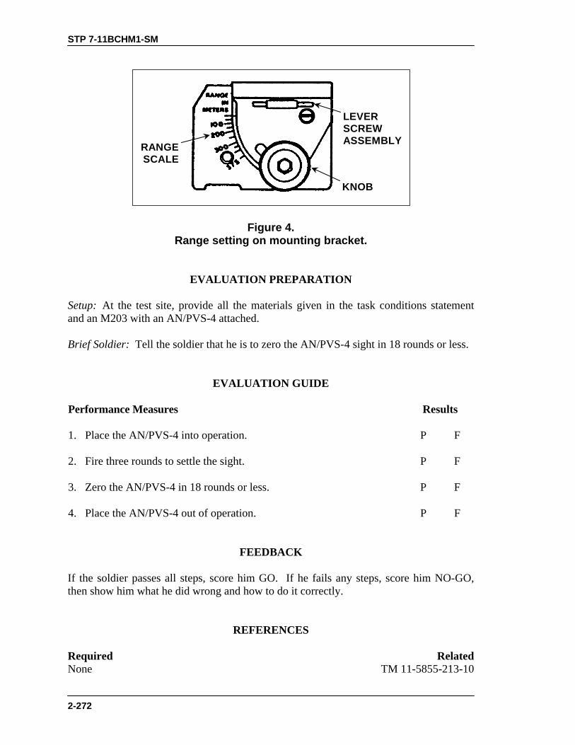
STP 7-11BCHM1-SM
2-272
RANGESCALE
KNOB
LEVERSCREWASSEMBLY
Figure 4. Range setting on mounting bracket.
EVALUATION PREPARATION Setup: At the test site, provide all the materials given in the task conditions statement and an M203 with an AN/PVS-4 attached. Brief Soldier: Tell the soldier that he is to zero the AN/PVS-4 sight in 18 rounds or less.
EVALUATION GUIDE
Performance Measures
Results
1. Place the AN/PVS-4 into operation.
P F
2. Fire three rounds to settle the sight.
P F
3. Zero the AN/PVS-4 in 18 rounds or less.
P F
4. Place the AN/PVS-4 out of operation. P F
FEEDBACK If the soldier passes all steps, score him GO. If he fails any steps, score him NO-GO, then show him what he did wrong and how to do it correctly.
REFERENCES Required Related None TM 11-5855-213-10

STP 7-11BCHM1-SM
2-273
ENGAGE TARGETS WITH AN M203 GRENADE LAUNCHER USING A NIGHT VISION SIGHT AN/PVS-4
071-315-2352 CONDITIONS During limited visibility conditions, given an M203 grenade launcher with a mounted, zeroed, and operational AN/PVS-4 night vision sight, engageable threat target(s), three rounds of 40-mm ammunition. STANDARDS Engage threat target(s) at 200 meters. Place 2 of 3 rounds within 5 meters of each other and disperse or destroy targets.
TRAINING AND EVALUATION Training Information Outline
1. Place sight into operation (see Task 071-315-0003, Operate a Night Vision Sight AN/PVS-4). 2. Use the sight reticle. The AN/PVS-4 sight reticle consists of two parts when used with the M203 (Figure 1). a. Use the upper part to determine range. b. Use the lower part to aim the weapon.
RANGESCALE
AIMINGPOINTS
Figure 1. Sight reticle.
3. Determine range. The vertical lines on the range scale show how far away a 6-foot-tall man is. a. Place the figure on the horizontal line and match it with the vertical line (A, Figure 2).

STP 7-11BCHM1-SM
2-274
b. Read the number at the bottom of the vertical line. That is the distance in hundreds of meters. c. If the figure is the same height as the vertical line above and below the horizontal line, divide the distance in half. In A, Figure 2, the man above the horizontal line is 400 meters away. In B, Figure 2, the man above and below the line is 200 meters away. 4. Set the range as determined on the range indicator of the mounting bracket (Figure 3).
DISTANCETO MAN IS400 METERS
DISTANCETO MAN IS200 METERS
Figure 2. Determination of range.
LEVERSCREWASSEMBLY
RANGESCALE
KNOB
Figure 3. Range settings on mounting bracket.
5. Engage the target. a. Place the aiming point of the sight reticle with the number corresponding to the range at the target’s center of mass (Figure 4). b. Fire the weapon using all marksmanship skills.

STP 7-11BCHM1-SM
2-275
106
84
432
Figure 4. Engagement of target at 200 meters.
EVALUATION PREPARATION Setup: At a live-fire M203 range, provide all the materials indicated in the task conditions statement. Turn off the sight after the evaluation. Brief Soldier: Tell the soldier that he is to engage a target at 200 meters with the M203 using an AN/PVS-4.
EVALUATION GUIDE
Performance Measures
Results
1. Place the AN/PVS-4 into operation.
P F

STP 7-11BCHM1-SM
2-276
EVALUATION GUIDE
Performance Measures
Results
2. Use the sight reticle to determine range.
P F
3. Set the range on the mounting bracket.
P F
4. Engage the target and place two of the three rounds within 5 meters of the target.
P F
FEEDBACK If the soldier passes all steps, score him GO. If he fails any steps, score him NO-GO, then show him what he did wrong and how to do it correctly.
REFERENCES Required Related None TM 11-5855-213-10

STP 7-11BCHM1-SM
2-277
M47 MEDIUM ANTITANK WEAPON
CONSTRUCT A FIGHTING POSITION FOR AN M47 MEDIUM ANTITANK WEAPON
071-052-0003 CONDITIONS Given an M47 medium antitank weapon (Dragon), a sector of fire, a location for the fighting position, an entrenching tool, overhead cover material, and a requirement to construct the position. STANDARDS Construct a fighting position that provides coverage of the assigned sectors of fire; enough room to accommodate firing and preparation of another Dragon round; cover and protection from small-arms fire by means of natural or man-made parapets; and concealment that prevents easy detection by a soldier using binoculars 1,000 meters to the front of the position.
TRAINING AND EVALUATION Training Information Outline
TRAININGNOTE:
Like any other weapon organic to the platoon, the Dragon can beemployed from either hasty or improved positions. A fighting position isa firing position sited and oriented to cover a sector of fire andconstructed to accommodate the weapons system and its firer.
1. Prepare a position. After receiving a sector of fire and firing location from your squad leader, prepare and position the weapon to cover the sector. See Figure 1 for an example of a Dragon fighting position. Clear fields of fire as necessary. Camouflage the position using available materials. Improve the position as time permits. Remember— a. The muzzle end of the Dragon must extend 6 inches beyond the front of the trench. b. The rear of the Dragon must extend over the rear of the trench.

STP 7-11BCHM1-SM
2-278
Figure 1. Example of a Dragon firing position.
2. Construct a position. Make the position three M16s long and in an inverted “V” shape, waist-deep, and waist-wide plus about 6 inches (A, Figure 2). a. Make the front parapet (B, Figure 2) one M16 long and wide, and two helmets high. Make the flank parapets (C, Figure 2) one M16 wide, two helmets high, and long enough to give good flank protection.
FLANKPARAPET
OVERHEADCOVER
OVERHEADCOVER
FLANKPARAPET
FRONTPARAPET
BIPODTRENCH
TRENCHGRENADESUMP
SECTOROF
FIRE
SECTOROF
FIRE
E
D
C
B
A
D
C
Figure 2. Fighting position layout.

STP 7-11BCHM1-SM
2-279
b. Dig the bipod trench for each sector of fire (D, Figure 2) 4 to 6 inches forward of the main trench. The bipod trench should be two helmets long, one helmet wide, and 6 inches deep. c. Slope the grenade sump (E, Figure 2) forward at a 45-degree angle. Make it as deep and long as one entrenching tool and as wide as one entrenching tool blade. Slope the floor of the main trench gently from each end to the center and from rear to front. d. Construct the overhead cover at each end of the trench as follows: NOTE: The overhead cover at each end should be large enough to provide protection
for one man and extra rounds. (1) Mark the position of the overhead cover, making a rectangle one M16 wide by two M16s long at each end of the trench. (2) Dig out the soil within the marked area (save any sod) to about 12 inches. The area dug must extend at least 18 inches beyond each side of the trench (Figure 3). (3) Place 4- to 6-inch-thick logs or other supporting material into each hole (Figure 4). (4) Fill the remainder of the hole with dirt until it is about ground level. Use sod to cover the dirt (Figure 5). (5) Enter the trench and dig a cave-like hole under the logs or supporting material (Figure 6). When constructed, the flank parapets will partly hide the overhead cover (Figure 2).
Dig down about 30 cm (12 in) beneath where you planto place the overhead cover at each end of the position.Continue digging the area about 45 cm (16 in) beyondboth sides of the hole. Make each area about 1 meter(3 ft) wide. Save the sod to use later for camouflage.
12"
18"
18"
DIGGING OUT FLANK OVERHEAD COVER
Figure 3. Flank overhead cover layout.
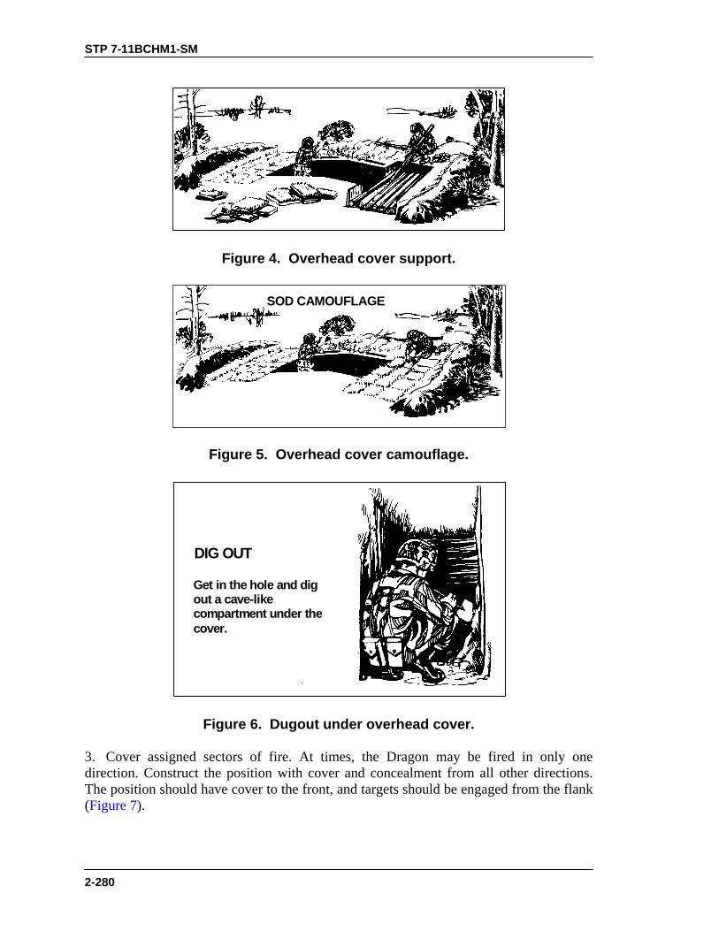
STP 7-11BCHM1-SM
2-280
Figure 4. Overhead cover support.
SOD CAMOUFLAGE
Figure 5. Overhead cover camouflage.
DIG OUT
Get in the hole and digout a cave-likecompartment under thecover.
Figure 6. Dugout under overhead cover.
3. Cover assigned sectors of fire. At times, the Dragon may be fired in only one direction. Construct the position with cover and concealment from all other directions. The position should have cover to the front, and targets should be engaged from the flank (Figure 7).

STP 7-11BCHM1-SM
2-281
FIRE ONLY TO THE OBLIQUE
Figure 7. Front cover, flank engagement.
EVALUATION PREPARATION Setup: At the test site, provide all materials and equipment given in the task conditions statement. Brief Soldier: Tell the soldier that he will construct a fighting position for a Dragon. Assign the weapon location and sector of fire.
EVALUATION GUIDE
Performance Measures
Results
1. Prepare a position and place the weapon to cover the sector. a. The muzzle extends 6 inches beyond the trench front.
P F
b. The rear of the weapon extends over the rear of the trench.
2. Construct a position. a. Prepare a position three M16s long, inverted “V” shape, waist-deep, and waist-wide plus 6 inches.
P F
b. Construct the front parapet one M16 long, one M16 wide, and twohelmets high.
c. Dig the bipod trench. The back of the bipod trench is 4 to 6 inches forward of the main trench. The bipod trench is two helmets long, one helmet wide, and 6 inches deep.
d. Prepare the grenade sump. e. Construct the overhead cover.
STP 7-11BCHM1-SM
2-282
EVALUATION GUIDE
Performance Measures
Results
NOTE: The cover at each end should be large enough to protect oneman and the weapon’s extra rounds.
(1) Mark a rectangle one M16 wide by two M16s long. (2) Dig out rectangle.
(3) Place supporting material into hole. (4) Fill hole. (5) Dig under supporting material.
3. Ensure position covers assigned sectors of fire. P F
FEEDBACK If the soldier passes all steps, score him GO. If he fails any steps, score him NO-GO, then show him what he did wrong and how to do it correctly. NOTE: During training, comply with unit SOP, local regulations, or both concerning
the cutting of live vegetation, digging holes, and preventing erosion.
REFERENCES Required Related None FM 7-8
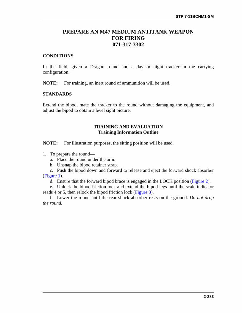
STP 7-11BCHM1-SM
2-283
PREPARE AN M47 MEDIUM ANTITANK WEAPON FOR FIRING 071-317-3302
CONDITIONS In the field, given a Dragon round and a day or night tracker in the carrying configuration. NOTE: For training, an inert round of ammunition will be used. STANDARDS Extend the bipod, mate the tracker to the round without damaging the equipment, and adjust the bipod to obtain a level sight picture.
TRAINING AND EVALUATION Training Information Outline
NOTE: For illustration purposes, the sitting position will be used. 1. To prepare the round— a. Place the round under the arm. b. Unsnap the bipod retainer strap. c. Push the bipod down and forward to release and eject the forward shock absorber (Figure 1). d. Ensure that the forward bipod brace is engaged in the LOCK position (Figure 2). e. Unlock the bipod friction lock and extend the bipod legs until the scale indicator reads 4 or 5, then relock the bipod friction lock (Figure 3). f. Lower the round until the rear shock absorber rests on the ground. Do not drop the round.
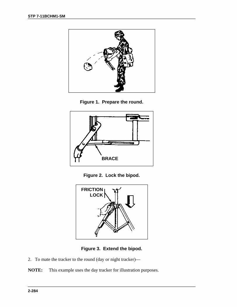
STP 7-11BCHM1-SM
2-284
Figure 1. Prepare the round.
BRACE
Figure 2. Lock the bipod.
FRICTIONLOCK
Figure 3. Extend the bipod.
2. To mate the tracker to the round (day or night tracker)— NOTE: This example uses the day tracker for illustration purposes.
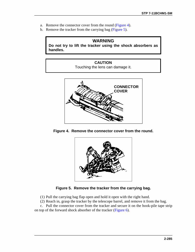
STP 7-11BCHM1-SM
2-285
a. Remove the connector cover from the round (Figure 4). b. Remove the tracker from the carrying bag (Figure 5).
WARNINGDo not try to lift the tracker using the shock absorbers ashandles.
CAUTIONTouching the lens can damage it.
CONNECTORCOVER
Figure 4. Remove the connector cover from the round.
Figure 5. Remove the tracker from the carrying bag.
(1) Pull the carrying bag flap open and hold it open with the right hand. (2) Reach in, grasp the tracker by the telescope barrel, and remove it from the bag. c. Pull the connector cover from the tracker and secure it on the hook-pile tape strip on top of the forward shock absorber of the tracker (Figure 6).

STP 7-11BCHM1-SM
2-286
HOOK-PILETAPE
CONNECTORCOVER
Figure 6. Remove the connector cover from the tracker.
WARNINGEnsure that the safety and trigger are not pressed whilemating the tracker to the round.
d. Place the tracker guide pins in the slots of the round’s tracker bracket guide rails (Figure 7). e. Slide the tracker firmly to the rear, using both hands, until the spring clip locks the guide pins in place (Figure 8).
TRACKERBRACKET
Figure 7. Align tracker and tracker bracket.

STP 7-11BCHM1-SM
2-287
TRACKERBRACKET
Figure 8. Lock the tracker to the tracker bracket.
f. If the tracker will not mate to the round: (1) Ensure that the connector covers on the round and on the tracker have been removed. (2) Check the guide pins on the tracker to ensure that they are not bent. If they are, notify your supervisor. (3) Check the tracker bracket on the round. If the tracker bracket is bent or distorted, secure a new round or notify your supervisor. (4) Check the connectors of the tracker and round. If either is damaged, notify your supervisor. 3. To prepare for firing— a. Remove the lens cover and secure it on the hook-pile tape strip on the front shock absorber of the tracker (Figure 9). b. Assume a firing position and place the round on your shoulder. c. Look through the tracker. If the reticle is tilted (A, Figure 10), adjust the bipod friction lock and foot adjust (B, Figure 10) and obtain a level sight picture.
HOOK-PILETAPE
LENSCOVER
Figure 9. Remove the lens cover.

STP 7-11BCHM1-SM
2-288
FRICTIONLOCK
BIPOD FOOTADJUSTMENT
A
B
Figure 10. Level the sight picture.
EVALUATION PREPARATION Setup: At the test site, provide all the materials and equipment given in the task conditions statement. Brief Soldier: Tell the soldier to prepare the M47 medium antitank weapon for firing.
EVALUATION GUIDE
Performance Measures
Results
1. Prepare the round. a. Place round under arm.
P F
b. Unsnap bipod retainer strap. c. Release and eject forward shock absorber. d. Extend and lock bipod friction lock. e. Lower round (until rear shock absorber rests on the ground).
2. Mate the tracker to the round (day or night tracker). a. Remove connector cover.
P F
b. Remove tracker from carrying bag. c. Secure connector cover to forward shock absorber. d. Place tracker guide pins in guide rail slots.
STP 7-11BCHM1-SM
2-289
EVALUATION GUIDE
Performance Measures
Results
e. Lock tracker in place. f. If the tracker will not mate to the round: (1) Check round and tracker connector covers.
(2) Check tracker guide pins. (3) Check tracker bracket. (4) Check tracker and round connectors.
3. Prepare for firing. a. Remove and secure lens cover.
P F
b. Assume firing position and place round on shoulder. c. Look through tracker and obtain sight picture.
FEEDBACK If the soldier passes all steps, score him GO. If he fails any steps, score him NO-GO, then show him what he did wrong and how to do it correctly.
REFERENCES Required Related None TM 9-1425-484-10

STP 7-11BCHM1-SM
2-290
OPERATE A NIGHT VISION SIGHT AN/TAS-5 071-052-0005
CONDITIONS During darkness, given a night vision sight AN/TAS-5, an M222 round, a coolant cartridge, and a nightsight battery. STANDARDS Prepare the sight for operation and correctly mount it on the M222 round; acquire a target by adjusting the sight controls without damaging the equipment.
TRAINING AND EVALUATION Training Information Outline
1. Prepare the night tracker for use. a. When removing the tracker from the rucksack, hold it by the firing mechanism. b. Install the coolant cartridge: (1) Locate the actuator switch on the right side of the coolant guage. The switch has four positions (Figure 1). A decal on top of the tracker shows these positions.
COOLANTGUAGE
ACTUATORSWITCH
Figure 1. Coolant gauge and actuator switch.
CAUTIONA coolant cartridge must always be installed on the night trackerexcept during cartridge exchange.
(2) Place the actuator switch straight down. This is the RELEASE position (Figure 2).

STP 7-11BCHM1-SM
2-291
RELEASE
AIR/BATTCHECKOFF/LOCK
ON
Figure 2. Night tracker actuator switch.
(3) Remove the coolant cartridge from the actuator assembly (Figure 3).
COOLANTROLLERS
Figure 3. Removal and installation of the coolant cartridge.
NOTE: Return all empty coolant cartridges to unit supply for recharging. (4) Slide the new coolant cartridge in the front of the night tracker, under the rollers, and back into the actuator assembly. While holding the cartridge in place, rotate the actuator switch counterclockwise to the OFF/LOCK position (Figure 4). c. Install the battery: (1) Move the battery retainer clip to the open position (Figure 5). (2) Align the battery over the battery guide pins (A, Figure 6).
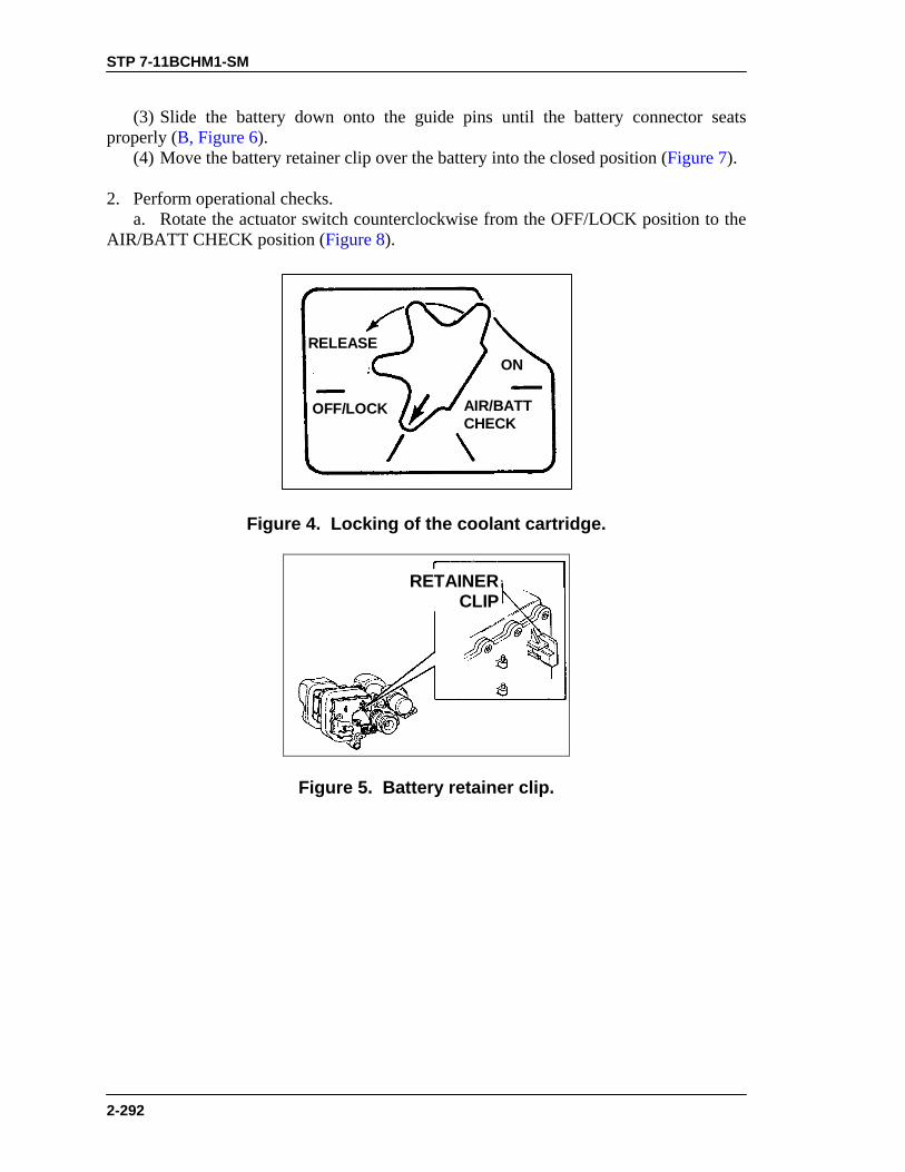
STP 7-11BCHM1-SM
2-292
(3) Slide the battery down onto the guide pins until the battery connector seats properly (B, Figure 6). (4) Move the battery retainer clip over the battery into the closed position (Figure 7). 2. Perform operational checks. a. Rotate the actuator switch counterclockwise from the OFF/LOCK position to the AIR/BATT CHECK position (Figure 8).
RELEASE
AIR/BATTCHECK
OFF/LOCK
ON
Figure 4. Locking of the coolant cartridge.
RETAINERCLIP
Figure 5. Battery retainer clip.
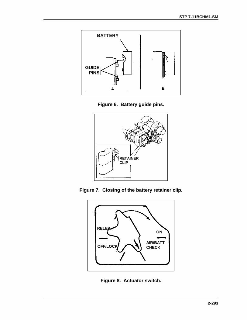
STP 7-11BCHM1-SM
2-293
BATTERY
GUIDEPINS
Figure 6. Battery guide pins.
RETAINERCLIP
Figure 7. Closing of the battery retainer clip.
RELEA
AIR/BATTCHECKOFF/LOCK
ON
Figure 8. Actuator switch.
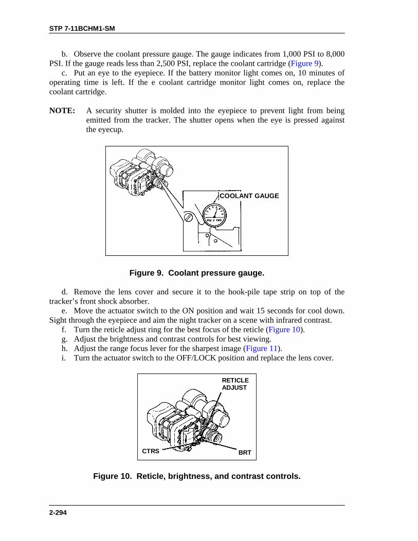
STP 7-11BCHM1-SM
2-294
b. Observe the coolant pressure gauge. The gauge indicates from 1,000 PSI to 8,000 PSI. If the gauge reads less than 2,500 PSI, replace the coolant cartridge (Figure 9). c. Put an eye to the eyepiece. If the battery monitor light comes on, 10 minutes of operating time is left. If the e coolant cartridge monitor light comes on, replace the coolant cartridge. NOTE: A security shutter is molded into the eyepiece to prevent light from being
emitted from the tracker. The shutter opens when the eye is pressed against the eyecup.
COOLANT GAUGE
Figure 9. Coolant pressure gauge.
d. Remove the lens cover and secure it to the hook-pile tape strip on top of the tracker’s front shock absorber. e. Move the actuator switch to the ON position and wait 15 seconds for cool down. Sight through the eyepiece and aim the night tracker on a scene with infrared contrast. f. Turn the reticle adjust ring for the best focus of the reticle (Figure 10). g. Adjust the brightness and contrast controls for best viewing. h. Adjust the range focus lever for the sharpest image (Figure 11). i. Turn the actuator switch to the OFF/LOCK position and replace the lens cover.
RETICLEADJUST
CTRS BRT
Figure 10. Reticle, brightness, and contrast controls.

STP 7-11BCHM1-SM
2-295
RANGE FOCUS LEVER
Figure 11. Range focus lever.
3. Mate the night tracker to the round. a. Remove the connector cover from the connector on the night tracker. b. Remove the connector cover from the connector on the round. c. Place the tracker guide pins in the slots of the tracker bracket guide rails on the round.
WARNINGDo not press the safety or the trigger while mating thetracker to the round.
d. Slide the tracker firmly to the rear, using both hands, until the spring clip locks the guide pins in place. e. Remove the lens cover and secure it to the hook-pile tape strip. f. The night tracker is ready to use.
EVALUATION PREPARATION Setup: At the test site, provide two coolant cartridges, each containing over 2,500 PSI; a battery; a night tracker; and an expended round. Tell the soldier that he is to replace the coolant cartridge. NOTE: Test personnel are responsible for removing the tracker from the round, the
battery from the tracker, and for returning the tracker to the rucksack. The tracker and round are in the same starting condition for each soldier tested.
Brief Soldier: Tell the soldier to place the night tracker into operation and mate the tracker to the round.
STP 7-11BCHM1-SM
2-296
EVALUATION GUIDE
Performance Measures
Results
1. Prepare a night tracker. a. Replace coolant cartridge. b. Install the battery.
P F
2. Perform operational checks. a. Check coolant pressure.
P F
b. Check battery and coolant monitor lights. c. Adjust reticle. d. Adjust the brightness and contrast. e. Adjust the range focus. f. Replace the lens cover.
3. Mate the tracker to the round. a. Remove the connector covers on the tracker and round. b. Secure the tracker to the guide rails on the round.
P F
4. Acquire target by adjusting the sight controls without damagingthe equipment.
P F
FEEDBACK
If the soldier passes all steps, score him GO. If he fails any steps, score him NO-GO, then show him what he did wrong and how to do it correctly.
REFERENCES Required Related None TM 9-1425-484-10

STP 7-11BCHM1-SM
2-297
ENGAGE TARGETS WITH AN M47 MEDIUM ANTITANK WEAPON
071-052-0006 CONDITIONS Given a Dragon tracker mated to a round of ammunition, and actual or sized-to-scale targets. STANDARDS Correctly determine if three targets are in range and if they are engageable.
TRAINING AND EVALUATION Training Information Outline
1. Acquire the target. a. Look through the tracker (Figure 1). b. Use the sight adjusting ring to focus the tracker. c. Rotate the eye guard to fit your face (Figure 2).
Figure 1. View through the tracker.

STP 7-11BCHM1-SM
2-298
ADJUSTING RING
EYEGUARD
Figure 2. Location of sight adjusting ring.
2. Determine if the target is in or out of range and whether it is a frontal (A, Figure 3), flank (B, Figure 3), or oblique target (C, Figure 3).
A B C
Figure 3. Frontal, flank, and oblique targets.
a. Flanking targets (full stadia). Adjust the sight picture by moving the launcher to center the target between the stadia lines (Figure 4). NOTE: At the maximum effective range of 1,000 meters, a target 20 feet (6.09
meters) long will touch both the larger stadia lines. Thus, a target that does not touch both stadia lines is beyond 1,000 meters.
b. Frontal (head-on) or rear (going away) targets (half-stadia). Adjust the sight picture by moving the launcher. Align the vertical cross hair and one of the stadia lines on the target (Figure 5).

STP 7-11BCHM1-SM
2-299
NOTE: At the maximum effective range of 1,000 meters, a target 10 feet (3.05 meters) wide will touch the center cross hair and one of the stadia lines. Thus, a target that exceeds the width between the center cross hair and one of the stadia lines is nearer than 1,000 meters, and one that does not touch both the cross hair and one of the stadia lines is farther than 1,000 meters.
OUT OF RANGEIN RANGE
STADIALINES
Figure 4. Range determination for flank target.
OUT OF RANGEIN RANGE
STADIALINES
Figure 5. Range determination for frontal or rear target.
c. Oblique targets. (1) If more of the flank is visible than the front or rear of the target, use the full-stadia method. (2) If more of the front or rear is visible than the flank, use the half-stadia method (Figure 6 and Figure 7).

STP 7-11BCHM1-SM
2-300
OUT OF RANGEIN RANGE
STADIALINES
Figure 6. Range determination for oblique target, more flank visible.
STADIALINES
Figure 7. Range determination for oblique target, more front or rear visible.
3. Determine if the target is engageable (Figure 8). a. If the vehicle may be able to reach cover to protect itself from your Dragon, then you have to determine whether you can hit the target before it does. Use the tracker sight to help you decide. Line it up directly in front of your target. If there are no obstructions or covered areas along the expected path of the target and the target is moving 35 MPH or less, you can successfully launch your missile and destroy the target. b. If the target definitely cannot reach cover in time, place the cross hairs center of mass and fire (Figure 9). c. If the target will definitely reach cover in time, do not fire (Figure 10).

STP 7-11BCHM1-SM
2-301
Figure 8. Target may or may not reach cover.
Figure 9. Target cannot reach cover in time.
Figure 10. Target can reach cover in time.
EVALUATION PREPARATION Setup: At the test site, provide all materials and equipment given in the task conditions statement. Brief Soldier: Tell the soldier to determine if the given targets are engageable or not.
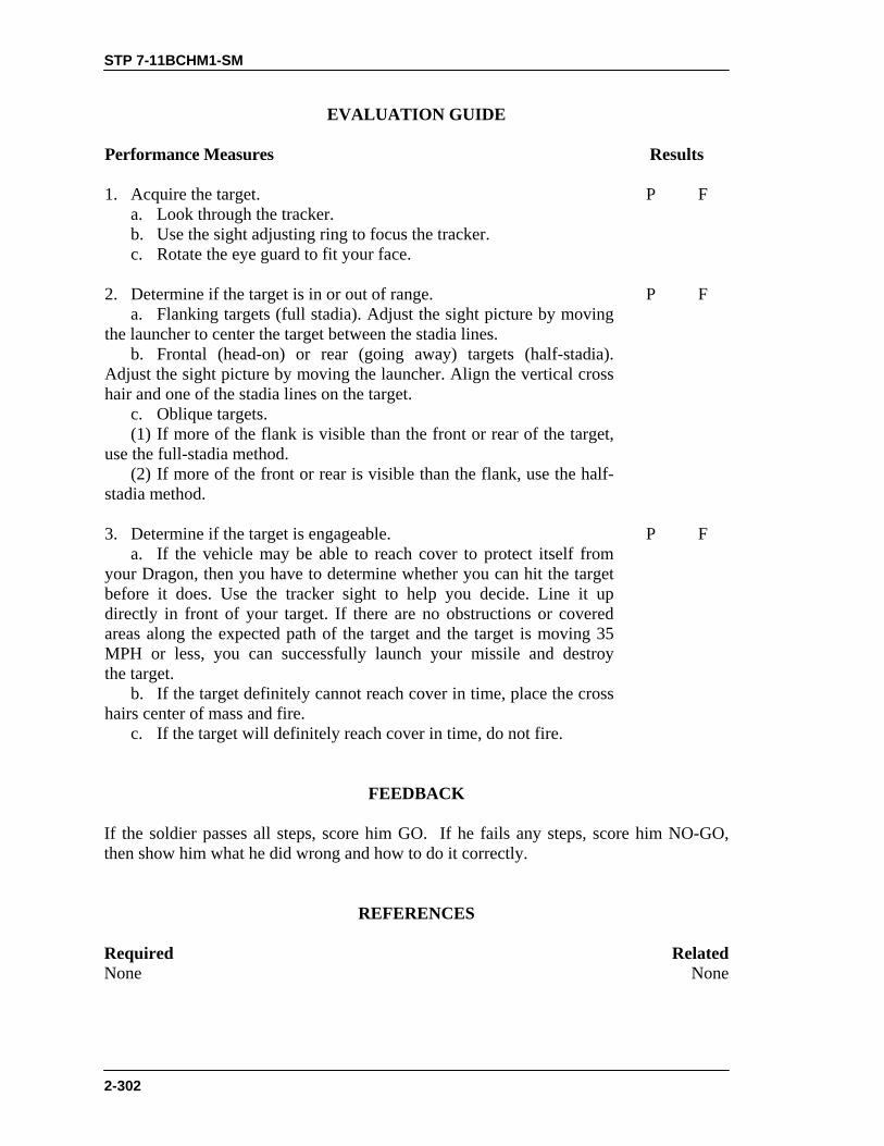
STP 7-11BCHM1-SM
2-302
EVALUATION GUIDE
Performance Measures
Results
1. Acquire the target. a. Look through the tracker.
P F
b. Use the sight adjusting ring to focus the tracker. c. Rotate the eye guard to fit your face.
2. Determine if the target is in or out of range. a. Flanking targets (full stadia). Adjust the sight picture by moving the launcher to center the target between the stadia lines.
P F
b. Frontal (head-on) or rear (going away) targets (half-stadia). Adjust the sight picture by moving the launcher. Align the vertical cross hair and one of the stadia lines on the target.
c. Oblique targets. (1) If more of the flank is visible than the front or rear of the target, use the full-stadia method.
(2) If more of the front or rear is visible than the flank, use the half-stadia method.
3. Determine if the target is engageable. a. If the vehicle may be able to reach cover to protect itself from your Dragon, then you have to determine whether you can hit the target before it does. Use the tracker sight to help you decide. Line it up directly in front of your target. If there are no obstructions or covered areas along the expected path of the target and the target is moving 35 MPH or less, you can successfully launch your missile and destroy the target.
P F
b. If the target definitely cannot reach cover in time, place the cross hairs center of mass and fire. c. If the target will definitely reach cover in time, do not fire.
FEEDBACK
If the soldier passes all steps, score him GO. If he fails any steps, score him NO-GO, then show him what he did wrong and how to do it correctly.
REFERENCES
Required Related None None

STP 7-11BCHM1-SM
2-303
PERFORM MISFIRE PROCEDURES ON AN M47 MEDIUM ANTITANK WEAPON
071-317-3306 CONDITIONS In a field environment, given an M47 medium antitank weapon (Dragon), a tracker, and a misfire situation. STANDARDS Perform immediate action for an M47 with a cold and a hot thermal battery.
TRAINING AND EVALUATION Training Information Outline
1. If the Dragon fails to fire, immediately resqueeze the trigger and continue tracking the target for 15 seconds. 2. If the round still has not fired, cautiously feel near the thermal battery (Figure 1).
THERMALBATTERY
Figure 1. Check the thermal battery.
3. When the thermal battery is hot, do the following: a. Remove the tracker from the round and place the round on the ground away from your firing site. Keep the round pointed toward the enemy; advise friendly troops in your vicinity of the misfire. b. Obtain a new round and mount the tracker on the new round. c. If possible, acquire the previous target and continue with the mission.
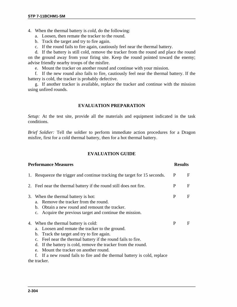
STP 7-11BCHM1-SM
2-304
4. When the thermal battery is cold, do the following: a. Loosen, then remate the tracker to the round. b. Track the target and try to fire again. c. If the round fails to fire again, cautiously feel near the thermal battery. d. If the battery is still cold, remove the tracker from the round and place the round on the ground away from your firing site. Keep the round pointed toward the enemy; advise friendly nearby troops of the misfire. e. Mount the tracker on another round and continue with your mission. f. If the new round also fails to fire, cautiously feel near the thermal battery. If the battery is cold, the tracker is probably defective. g. If another tracker is available, replace the tracker and continue with the mission using unfired rounds.
EVALUATION PREPARATION Setup: At the test site, provide all the materials and equipment indicated in the task conditions. Brief Soldier: Tell the soldier to perform immediate action procedures for a Dragon misfire, first for a cold thermal battery, then for a hot thermal battery.
EVALUATION GUIDE
Performance Measures
Results
1. Resqueeze the trigger and continue tracking the target for 15 seconds.
P F
2. Feel near the thermal battery if the round still does not fire.
P F
3. When the thermal battery is hot: a. Remove the tracker from the round.
P F
b. Obtain a new round and remount the tracker. c. Acquire the previous target and continue the mission.
4. When the thermal battery is cold: a. Loosen and remate the tracker to the ground.
P F
b. Track the target and try to fire again. c. Feel near the thermal battery if the round fails to fire. d. If the battery is cold, remove the tracker from the round. e. Mount the tracker on another round. f. If a new round fails to fire and the thermal battery is cold, replacethe tracker.

STP 7-11BCHM1-SM
2-305
FEEDBACK
If the soldier passes all steps, score him GO. If he fails any steps, score him NO-GO, then show him what he did wrong and how to do it correctly.
REFERENCES
Required Related None TM 9-1425-484-10

STP 7-11BCHM1-SM
2-306
RESTORE AN M47 MEDIUM ANTITANK WEAPON TO CARRYING CONFIGURATION
071-052-0004 CONDITIONS Given an M47 medium antitank weapon prepared for firing, and a requirement to restore it to the carrying configuration. STANDARDS Remove the tracker and store it in the carrying bag; restore the round to a safe carrying configuration.
TRAINING AND EVALUATION Training Information Outline
1. To remove the tracker from the round, depress the spring clip on the tracker. a. Replace the tracker lens cover. b. Remove the tracker from the round, and replace the connector cover on the tracker. c. Return the tracker to its carrying bag. 2. Restore the round to the carrying configuration. a. Replace the forward shock absorber. (1) Set the round in an upright position with the rear shock absorber resting on the ground. (2) While pushing down lightly on the bipod, press the bipod brace toward the round to lift it out of the locking slot. (3) Once the bipod brace is unlocked, push down on the bipod until the upper part of the bipod that attaches to the round is parallel with the muzzle of the launch tube. (4) Align the cut-out portion of the forward shock absorber with the bipod at the launch tube muzzle. (5) Push down on the shock absorber while lowering the bipod against the round. Ensure the upper part of the bipod engages the shock absorber. (6) Retract the bipod legs and secure them to the round with the retainer strap. b. Lift up on the forward shock absorber to ensure that it is secure. 3. Ensure the round is now in a safe-to-carry configuration.

STP 7-11BCHM1-SM
2-307
EVALUATION PREPARATION Setup: At the test site, provide an expended M47 medium antitank weapon and tracker prepared for firing. Place the forward shock absorber on the ground next to the weapon. Brief Soldier: Tell the soldier to dismount the tracker and return the weapon to the carrying configuration.
EVALUATION GUIDE
Performance Measures
Results
1. Remove the tracker. a. Replace the tracker lens cover.
P F
b. Remove the tracker. c. Replace the connector cover. d. Place the tracker in the carrying bag.
2. Restore the round to the carrying configuration. a. Release the bipod brace.
P F
b. Partially collapse the bipod legs. c. Replace the forward shock absorber. d. Lock the forward shock absorber to the round. e. Secure the bipod legs to the round.
FEEDBACK
If the soldier passes all steps, score him GO. If he fails any steps, score him NO-GO, then show him what he did wrong and how to do it correctly.
REFERENCES
Required Related None TM 9-1425-484-10

STP 7-11BCHM1-SM
2-308
M136 LAUNCHER
PREPARE AN M136 LAUNCHER FOR FIRING 071-054-0001
CONDITIONS Given an M136 launcher (AT4) and a requirement to prepare it for firing. STANDARDS Perform prefire checks on the M136 AT4 and prepare the round for firing.
TRAINING AND EVALUATION Training Information Outline
1. Perform the prefire checks. Because the M136 launcher is issued as a round of ammunition rather than as a weapon, the launcher is completely sealed. Therefore, inspection is limited to visual examination of the external components. The overall condition of the launcher should be inspected before it is used (Figure 1). The firer should ensure— a. The transport safety pin is in place and fully seated, and the lanyard is attached. b. The cocking lever is in the SAFE position and is folded down. c. The fire-through muzzle cover is intact. If the seal is torn, it should be removed to ensure that no foreign objects have gotten into the launcher. d. The launcher’s color-coded band is the correct color: black for high-explosive antitank; gold for target-practice tracers; and blue for field-handling trainers. e. The sights function properly. Open the sight covers to ensure the sights pop up and are not damaged. f. The red safety catch does not move when depressed. g. The rear seal is not damaged. h. The shoulder stop is not broken or damaged and it unsnaps and folds down. i. The carrying sling is not frayed and is attached to the launcher. j. The launcher body has no cracks, dents, or bulges.

STP 7-11BCHM1-SM
2-309
LAUNCHER BODY
FORWARDSAFETY COLOR-CODED
BAND--BLACKWITH YELLOWBAND INSIDE
FIRE-THRUMUZZLECOVER
CARRYING SLING
COCKING LEVER
SHOULDER STOPREDTRIGGERBUTTON
TRANSPORTSAFETY PIN
REARSEAL
SIGHTS
Figure 1. Parts of the M136 launcher to be inspected.
2. Prepare the launcher for firing. Preparation procedures are— a. Remove the launcher from the carrying position and cradle it with the left arm (Figure 2). b. While cradling the launcher, pull the transport safety pin with the right hand and release it (Figure 3). NOTE: Ensure the transport safety pin is attached to the launcher by its lanyard. • If the launcher has no lanyard, place the transport safety pin in
your pocket. • If the launcher remains unfired, reinsert the transport safety pin.
WARNINGS• Make sure personnel wear earplugs.• Point the weapon toward the target.• Clear the backblast area.
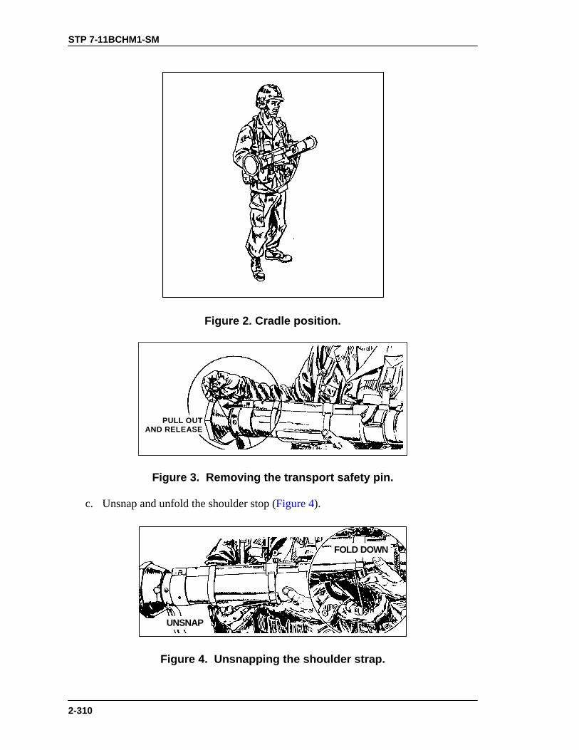
STP 7-11BCHM1-SM
2-310
Figure 2. Cradle position.
PULL OUTAND RELEASE
Figure 3. Removing the transport safety pin.
c. Unsnap and unfold the shoulder stop (Figure 4).
FOLD DOWN
UNSNAP
Figure 4. Unsnapping the shoulder strap.

STP 7-11BCHM1-SM
2-311
d. With the shoulder stop in position, place the launcher on the right shoulder. e. With the launcher on the right shoulder and supported with the left hand, release the front sight by pressing down on the sight cover and sliding it to the rear. Release the rear sight by pressing down on the cover and sliding it forward. Sliding the covers off allows the sights to pop up. f. Check backblast area. g. Cock the launcher by unfolding the cocking lever with the right hand. Place the thumb of the right hand under the cocking lever. Grip the front of the firing mechanism for support. Push the cocking lever forward and down to the right. Let the cocking lever slide back (Figure 5).
CAUTIONDo not refold the cocking lever. Doing so interferes with thefunction of the firing mechanism.
h. Adjust the rear sight for the required range. (1) When closing the sight cover, set the sight on a range of 200 meters. Therefore, when the rear sight is uncovered, the battlesight setting is 200 meters. If the range to the target is more than 250 meters, adjust the sight to the range. When the range is 250 meters or less, no sight adjustment is required (Figure 6). (2) To adjust the rear sight range setting to more than 200 meters, turn the range knob clockwise (toward the muzzle). To decrease the range, turn the range knob counterclockwise (toward the gunner). There is a click at each 50-meter increment; this sound aids you during limited visibility (Figure 6).
PUSHFORWARD
DOWN TOTHE RIGHT
ANDRELEASE
Figure 5. Cocking the launcher.
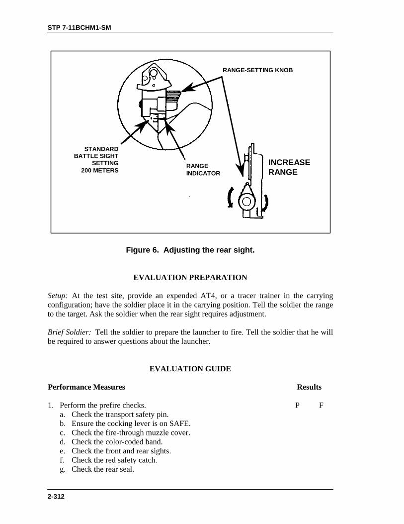
STP 7-11BCHM1-SM
2-312
STANDARDBATTLE SIGHT
SETTING200 METERS
RANGEINDICATOR
INCREASERANGE
RANGE-SETTING KNOB
Figure 6. Adjusting the rear sight.
EVALUATION PREPARATION Setup: At the test site, provide an expended AT4, or a tracer trainer in the carrying configuration; have the soldier place it in the carrying position. Tell the soldier the range to the target. Ask the soldier when the rear sight requires adjustment. Brief Soldier: Tell the soldier to prepare the launcher to fire. Tell the soldier that he will be required to answer questions about the launcher.
EVALUATION GUIDE Performance Measures
Results
1. Perform the prefire checks. a. Check the transport safety pin.
P F
b. Ensure the cocking lever is on SAFE. c. Check the fire-through muzzle cover. d. Check the color-coded band. e. Check the front and rear sights. f. Check the red safety catch. g. Check the rear seal.
STP 7-11BCHM1-SM
2-313
EVALUATION GUIDE Performance Measures
Results
h. Check the shoulder stop. i. Check the carrying sling. j. Check the body of the launcher.
2. Prepare the launcher for firing. a. Remove the transport safety pin.
P F
b. Unsnap and unfold the shoulder stop. c. Place the launcher on the right shoulder. d. Release the front and rear sights. e. Check the backblast area. f. Cock the launcher. g. Adjust the rear sight.
FEEDBACK
If the soldier passes all steps, score him GO. If he fails any steps, score him NO-GO, then show him what he did wrong and how to do it correctly.
REFERENCES Required Related None FM 23-25 TM 9-1340-886-12

STP 7-11BCHM1-SM
2-314
ENGAGE TARGETS WITH AN M136 LAUNCHER 071-054-0004
CONDITIONS Given an M136 launcher (AT4) prepared for firing, engageable targets, and a requirement to engage such targets. STANDARDS Destroy or disable the target with the M136 launcher.
TRAINING AND EVALUATION Training Information Outline
NOTE: The launcher can only be fired from the right shoulder. 1. Firing position. a. Four types of firing positions are used when firing the M136 launcher. (1) The standing position (Figure 1).
Figure 1. Standing position.
(2) The kneeling position with two variations (Figure 2).

STP 7-11BCHM1-SM
2-315
Figure 2. First and second kneeling positions.
(3) The sitting position with two variations (Figure 3).

STP 7-11BCHM1-SM
2-316
Figure 3. First and second sitting positions.
(4) The prone position (Figure 4).
Figure 4. Prone position.

STP 7-11BCHM1-SM
2-317
2. Use of the sights. a. Determine the range to the target. If the range is 250 meters or less, do not adjust the rear sight. If the range is more than 250 meters, adjust the rear sight to the required range.
WARNINGDo not place the eye against the rear sight when firing.Recoil may cause injury to the eye.
b. Obtain the correct sight picture (Figure 5). Align and properly place the sights in relation to the target. In Figure 5, notice that the top center of the front sight posts are in the center of the rear sight peephole. Ensure that the white line on the front sight is just inside the peephole.
2.5 TO 3 INCHES
PEEPHOLE
CORRECT SIGHT PICTURE
RIGHT LEAD POSTCENTER LEAD POST
TARGETLEFT LEAD POST
Figure 5. Correct sight picture.
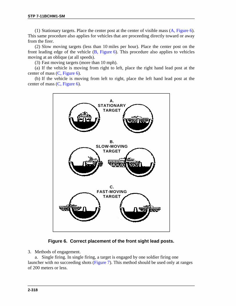
STP 7-11BCHM1-SM
2-318
(1) Stationary targets. Place the center post at the center of visible mass (A, Figure 6). This same procedure also applies for vehicles that are proceeding directly toward or away from the firer. (2) Slow moving targets (less than 10 miles per hour). Place the center post on the front leading edge of the vehicle (B, Figure 6). This procedure also applies to vehicles moving at an oblique (at all speeds). (3) Fast moving targets (more than 10 mph). (a) If the vehicle is moving from right to left, place the right hand lead post at the center of mass (C, Figure 6). (b) If the vehicle is moving from left to right, place the left hand lead post at the center of mass (C, Figure 6).
A.STATIONARY
TARGET
C.FAST-MOVING
TARGET
B.SLOW-MOVING
TARGET
Figure 6. Correct placement of the front sight lead posts.
3. Methods of engagement. a. Single firing. In single firing, a target is engaged by one soldier firing one launcher with no succeeding shots (Figure 7). This method should be used only at ranges of 200 meters or less.

STP 7-11BCHM1-SM
2-319
b. Sequence firing. In sequence firing, the target is engaged by one soldier equipped with two or more launchers (Figure 8). He observes the impact of the first round. If it is a hit, he continues to fire until the target is destroyed. If the first round was a miss, the soldier applies burst-on-target corrections until the target is hit.
WARNINGEnsure each firer is clear of the other’s backblast area.
Figure 7. Single firing.
Figure 8. Sequence firing.
c. Pair firing. In pair firing, two soldiers equipped with two or more rounds each engage a single target (Figure 9). The soldier who sees the target first identifies it, announces the estimated range and the lead that he will use—

STP 7-11BCHM1-SM
2-320
EXAMPLE: “BMP, one five zero meters, fast target” ...then he fires. The second soldier observes the impact and announces a revised estimate of range and lead (if appropriate) and fires. Each soldier continues exchanging range and lead information until the target is destroyed.
BMP, 150METERS, FAST
LOOKS LIKEHIS RANGE WASCORRECT, BUT
THE BMP ISGOING SLOWER
RANGECORRECT,
SPEED SLOW
Figure 9. Sequence firing by a pair of soldiers.
d. Volley firing. In volley firing, a single target is engaged by more than one soldier using the same sight data to fire one or more launchers (Figure 10). Volley firing should be used when the range to the target is known. Since more rounds are fired at the target, using this method increases the probability of hitting the target and obtaining a kill.

STP 7-11BCHM1-SM
2-321
Figure 10. Volley firing.
4. Target vulnerability. a. An armored vehicle usually has its heaviest armor on the front slopes. b. Gunners should try to engage the armored vehicle’s weak points, which are the sides and the rear (Figure 11).
TRY TOAIM HERE
BRDM
BMP
T62
Figure 11. Vulnerable points on an armored vehicle.

STP 7-11BCHM1-SM
2-322
EVALUATION PREPARATION Setup: At the test site, provide the soldier with a tracer trainer, targets to be engaged, a replica of the sights, and pictures of the vehicles. Brief Soldier: Tell the soldier which firing position to use and which target to engage. Tell him that he must answer questions about firing the launcher.
EVALUATION GUIDE
Performance Measures
Results
1. Assume the given firing position. a. Standing.
P F
b. Kneeling. c. Sitting. d. Prone.
2. Adjust the rear sight to the range when required.
P F
3. Use the correct sight placement to engage the targets. a. Stationary targets.
P F
b. Slow-moving targets. c. Fast-moving targets. d. Oblique-moving targets. e. Head-on or rear targets.
4. Answer the questions on the methods of engagement. a. Single firing.
P F
b. Sequence firing. c. Pair firing. d. Volley firing.
5. Answer the questions on a target’s weak points. P F
FEEDBACK
If the soldier passes all steps, score him GO. If he fails any steps, score him NO-GO, then show him what he did wrong and how to do it correctly.
REFERENCES
Required Related None FM 23-25 TM 9-1340-886-12

STP 7-11BCHM1-SM
2-323
PERFORM MISFIRE PROCEDURES ON AN M136 LAUNCHER 071-054-0003
CONDITIONS Given an armed M136 launcher (AT4) that has misfired. STANDARDS Apply misfire procedures so that the AT4 can be fired, or ensure the weapon cannot fire and inform the supervisor of the misfire.
TRAINING AND EVALUATION Training Information Outline
1. When the launcher fails to fire, immediately shout MISFIRE. 2. Continue to hold the launcher pointed in the area of the target. 3. Immediately check back blast area to ensure it is clear. 4. Recock the firing mechanism; aim, fully depress and hold down the red safety catch, and press the trigger. 5. If the launcher still fails to fire, repeat steps 1 through 4 above. 6. If the launcher again fails to fire: a. Release the red safety catch and return the cocking lever to the SAFE position. b. Remove the launcher from the shoulder while keeping the muzzle pointed toward the target area. c. While cradling the launcher with the left arm, reinsert the transport safety pin. NOTE: In a training situation only, place the launcher on your shoulder and keep it
oriented on the target area for at least 2 minutes. d. Carefully lay the launcher on the ground with sights up and muzzle pointed toward the target area. e. Notify supervisor. NOTE: In a training situation only, after inserting the transport safety pin, wait 2
minutes. Keep the launcher toward the target area.

STP 7-11BCHM1-SM
2-324
WARNINGDo not transport a launcher that has misfired.
EVALUATION PREPARATION
Setup: At the test site, provide an expended AT4 or a tracer trainer in the ready-to-fire configuration. Brief Soldier: Tell the soldier to assume a correct standing, ready-to-fire position with the launcher. Tell the soldier to go through the firing procedure. Tell him to go through the misfire procedures. NOTE: Score performance measures in sequence.
EVALUATION GUIDE
Performance Measures
Results
1. Shout MISFIRE.
P F
2. Keep launcher oriented on target area.
P F
3. Check the backblast area.
P F
4. Recock, aim, and try to fire.
P F
5. If the launcher fails to fire the second time, repeat Steps 1 through 4.
P F
6. If the launcher again fails to fire— a. Keep the muzzle pointed toward the target area.
P F
b. Reinsert the transport safety pin. c. Carefully laid the launcher on the ground with sights up and muzzle pointed toward the target area. d. Notify supervisor.
FEEDBACK
If the soldier passes all steps, score him GO. If he fails any steps, score him NO-GO, then show him what he did wrong and how to do it correctly.

STP 7-11BCHM1-SM
2-325
REFERENCES
Required Related None FM 23-25 TM 9-1340-886-12

STP 7-11BCHM1-SM
2-326
RESTORE AN M136 LAUNCHER TO CARRYING CONFIGURATION
071-054-0002 CONDITIONS Given an M136 launcher (AT4) prepared for firing and the requirement to restore the launcher to carrying configuration. STANDARDS Restore the launcher to a safe carrying configuration without damaging the equipment.
TRAINING AND EVALUATION Training Information Outline
1. When the launcher is prepared for immediate firing but is not fired, it is taken out of operation as follows: a. If the gunner is to remain in the same position — (1) He releases the red safety catch (this step applies only if the firing sequence has proceeded to this point). (2) He returns the cocking lever to the SAFE (uncocked) position by pushing it up and to the left, then pulling it rearward. He folds the cocking lever down. (3) Keeping the launcher pointed at the target area, he removes the launcher from his shoulder. (4) With the launcher cradled in his left arm, he replaces the transport safety pin. b. If the gunner is to move to another position, in addition to the steps shown above, he must— (1) Return the rear sight to the battlesight setting of 200 meters, fold down the front and rear sights, and close the sight covers. (2) Fold the shoulder stop and snap it back into position.
CAUTIONThe rear sight may be damaged if it is not returned to abattlesight setting of 200 meters before closing the sight cover.
2. The launcher is now in the carrying configuration and is safe and ready to transport.
EVALUATION PREPARATION Setup: At the test site, provide an expended AT4 or a tracer trainer. The AT4 or tracer trainer is in the ready to fire configuration.

STP 7-11BCHM1-SM
2-327
Brief Soldier: Tell the soldier to assume a correct standing, ready-to-fire position with the launcher. Once he has assumed the firing position, tell him to return the launcher to the carrying configuration. NOTE: The performance measures are scored in sequence.
EVALUATION GUIDE
Performance Measures
Results
1. Release the red safety catch.
P F
2. Return the cocking lever to the SAFE position.
P F
3. Remove the launcher from the shoulder and cradle it with the left arm.
P F
4. Replace the transport safety pin.
P F
5. Return the rear sight to the battlesight setting.
P F
6. Fold and cover the sights.
P F
7. Fold the shoulder stop and snap it in place. P F
FEEDBACK
If the soldier passes all steps, score him GO. If he fails any steps, score him NO-GO, then show him what he did wrong and how to do it correctly.
REFERENCES
Required Related None FM 23-25 TM 9-1340-886-12

STP 7-11BCHM1-SM
2-328
MINES AND DEMOLITIONS
LOCATE MINES BY VISUAL MEANS 051-192-1021
CONDITIONS Given a field location suspected of having mines and trip wires. STANDARDS Locate possible mine sites and visually search suspected areas for mines and trip wires. Do not overlook any visible mines, parts of mines, or trip wires.
EVALUATION PREPARATION Setup: Simulate a mined and trip-wired area. Brief Soldier: Tell the soldier to look at the terrain and visually locate possible mined and trip-wired areas.
EVALUATION GUIDE
Performance Measures
Results
1. Visually locate possible mine sites by locating the following areas: a. Likely avenues of approach.
P F
b. Key intersections and turnouts. c. Trails, paths, and cleared spots in wooded areas. d. Approaches and exits to bridges, fords, and tunnels. e. Wood lines. f. Depressions and ditches. g. Open fields or grassland.
2. Visually search possible mine sites for suspected mines and trip wires. a. Loose dirt, tall grass, trip wires, and any disturbed ground in or around helicopter landing sites.
P F
b. Signs of road repairs—holes filled with asphalt or other material. c. Mud smears, grass, sticks, loose dirt, dung, or other materialon roads.
d. Shoulders of roads at likely ambush sites. e. Trip wires near known or suspected AT mines. f. Signs placed in trees, on posts, or on stakes. g. Tunnels under roads.

STP 7-11BCHM1-SM
2-329
EVALUATION GUIDE
Performance Measures
Results
h. Any unusual or out of place material. i. Wilted plants or brush. j. Souvenirs such as flags, equipment, and supplies. k. Areas that local civilians avoid. l. Culverts and bridges.
3. Report all suspected areas to the team leader/squad leader. P F
FEEDBACK
If the soldier passes all steps, score him GO. If he fails any steps, score him NO-GO, then show him what he did wrong and how to do it correctly.
REFERENCES
Required Related None FM 20-32

STP 7-11BCHM1-SM
2-330
NEUTRALIZE MINES 051-193-1025
CONDITIONS Given an area where friendly or enemy mines have been located, demolition equipment, explosives, material for tripod (or A-frame), a 50-meter rope (or wire) with or without grapnel, and instructions on the method of neutralization to the used. STANDARDS Remove or destroy mines in place without injuring personnel.
EVALUATION PREPARATION Setup: Provide inert, emplaced, uncovered, and marked mines with and without antihandling devices; inert explosives; and other items listed in the conditions statement. Brief Soldier: Have the soldier destroy a mine in place, and remove another mine with a rope or wire.
EVALUATION GUIDE
Performance Measures
Results
WARNINGChemical mines should not be destroyed inplace. Soviet/Warsaw Pact mines cannot bedisarmed. Proceed with extreme caution.
NOTE: All mines are considered to be equipped with antihandling devices until proven otherwise.
1. Neutralize enemy mines with explosives. a. Ensure that all personnel are at least 300 meters from the mine. b. Place a 1-pound block of explosives within 6 inches of the mine and detonate.
P F
2. Neutralize the mine by throwing a grapnel with rope or wire attached to pull trip wires and tilt rods.
P F

STP 7-11BCHM1-SM
2-331
EVALUATION GUIDE
Performance Measures
Results
3. Remove the mine by lifting and dragging it out of the immediate area with a rope or wire. a. Set up a tripod or A-frame with available materials, if needed, to lift the mine out of its hole. b. Carefully uncover as much of the mine as necessary to expose the handle or other projection, and attach a rope or wire with grapnel. Use expedient hooks, if needed.
P F
NOTE: Do not move the mine while attached to wire, rope, or grapnel, which might detonate the antihandling device.
c. Stretch the rope across the tripod. d. Take cover or lay prone at least 50 meters away. e. Pull the opposite end of the rope so the mine is lifted straight up. f. Wait 5 minutes before approaching the mine to guard against delayed firing mechanism.
WARNINGIf the mine must be removed by hand, call forexplosive ordnance disposal personnel.
4. Neutralize friendly mines. a. Use explosives or rope on mines that definitely have antihandling devices that the soldier did not install. b. Use rope on mines that may have antihandling devices.
P F
NOTE: Any mines that are not booby trapped, damaged, malfunctioning, or continuously observed must be removed by the use of explosives.
5. Complete all work without injury to personnel. P F
FEEDBACK
If the soldier passes all steps, score him GO. If he fails any steps, score him NO-GO, then show him what he did wrong and how to do it correctly.

STP 7-11BCHM1-SM
2-332
REFERENCES
Required Related None FM 20-32 FM 5-101

STP 7-11BCHM1-SM
2-333
INSTALL A MECHANICAL AMBUSH 071-098-0002
CONDITIONS In a field location, given a bandoleer containing an M18A1 Claymore mine complete with accessories, a roll of trip wire, a plastic spoon or other nonconductor of electricity, a power source (a battery with at least 3 volts), a clothespin, small nail, knife, and the area to be converted. STANDARDS Position and aim the Claymore to cover the target area. Secure the trip wires so the mine does not move when it is activated. Camouflage wires and stakes to prevent detection. Properly connect the power source.
TRAINING AND EVALUATION Training Information Outline
1. Laying and aiming. a. Laying. Check to see that the mine and all accessories are in the bandoleer. Remove the electrical firing wire, leaving the mine and other accessories in the bandoleer. (1) Secure the shorting plug end at the trip wire position. Place the bandoleer on your shoulder and unroll the firing wire to the position selected for emplacing the mine. (2) Remove the mine from the bandoleer; position the mine with the surface marked FRONT TOWARD ENEMY and the arrows on top of the mine pointing in the direction of the enemy or pointing to the desired area of fire. b. Aiming (knife-edge sight). Select an aiming point at ground level about 50 meters (150 feet) in front of the mine. Position the eye 15 centimeters (6 inches) to the rear of the sight. Aim the mine by aligning the two edges of the sight with the aiming point (Figure 1).

STP 7-11BCHM1-SM
2-334
6 IN
50 METERS
LINE OF SIGHT
Figure 1. Aiming of the mine.
2. Preparing the firing wire. Cut the combination shorting plug and dust cover from the end of the firing wire. Remove about 1 inch of insulation from each of the cut wires. Twist the ends of the wires together to prevent static electricity from entering the firing wire and detonating the blasting cap. These wires will later be connected to the power source. 3. Installing the firing devices. a. Prepare the clothespin (Figure 2). b. Form a loop in each end of the cut wire (Figure 2). Fit a wire loop over each jaw of the clothespin. Ensure that the wires are seated in the clothespin grooves. Twist each wire until it is secured tightly to the clothespin. Ensure that the wires touch when the clothespin jaws are shut. NOTE: The firing device (plastic spoon and clothespin) may be constructed of any
nonconductive material (sticks, wood, or plastic). The material used to replace the clothespin must be under tension so it will snap together for firm contact of the wires to complete the firing circuit and detonate the mine.
CUT ONE WIRE TO CONNECT FIRING DEVICE
1. SPLIT FIRING WIRE
3. CUT GROOVES INTOJAWS OF CLOTHESPIN
SEPARATEWIRES HERE
2. CUT ONE WIRE ANDFORM TWO BAREWIRE LOOPS
1 METER
Figure 2. Preparation of the clothespin firing device.

STP 7-11BCHM1-SM
2-335
4. Connecting the trip wire (Figure 3). Attach one end of the trip wire to a plastic spoon (or other nonconductor). Connect the other end of the trip wire firmly to a tree or stake on the opposite side of the target area. Insert the spoon between the jaws of the clothespin. Place the trip wire about ankle-high to prevent easy detection by the enemy.
TRIP WIRE
PLASTICSPOON
FIRING WIRE
SPOON
IMPROVISED CLOTHESPINFIRING DEVICE
TO POWERSOURCE
TRIP WIRE
NAIL
STAKE
Figure 3. Completion of the firing device.
5. Arming and electrical firing. a. Secure the firing wire about 1 meter from the side of the mine so the mine will not be mislaid if the firing wire is disturbed. Insert the blasting cap into either detonator well and lock it in using the shipping plug priming adapter. b. Connect the power source. Figure 4 shows an example of a mechanical ambush.

STP 7-11BCHM1-SM
2-336
FIRINGDEVICE
60º
ENEMY
KILL
ZONE
TRIP WIRESTAKE
STAKEFIRING WIRE
POWERSOURCE
20M
20M
Figure 4. Example layout of the mechanical ambush.
CAUTION
Ensure that the handle of the spoon is securely seated betweenthe jaws of the clothespin. Ensure that the trip wire is not tootight and the area is clear of any objects that might fall on thetrip wire, causing the mine to detonate prematurely. Separatethe twisted ends of the firing wire and attach the ends to thepower source. The power source must produce at least 3 voltsof electricity.
WARNINGIn a training situation, do not try to install a live Claymoreduring inclement weather.
EVALUATION PREPARATION Setup: At the test site, provide all the equipment and information given in the task conditions statement. Use an INERT Claymore mine for training. Brief Soldier: Tell the soldier to emplace a mechanical ambush using the equipment given. Show him where to emplace the mine and the trip wire, and show him the ambush area.

STP 7-11BCHM1-SM
2-337
WARNINGDO NOT use live mines for test purposes.
EVALUATION GUIDE
Performance Measures
Results
1. Emplace the trip wire stakes.
P F
2. Secure the shorting plug of the firing wire to the trip wire stake that is used for the firing device.
P F
3. Unroll the firing wire to the position selected to emplace the mine.
P F
4. Emplace and aim the mine to cover the ambush area.
P F
5. Prepare the firing wire to be attached to the clothespin and the power source.
P F
6. Prepare the clothespin as a firing device.
P F
7. Prepare the trip wire using the plastic spoon (or other nonconductor) and attach the trip wire to the far stake.
P F
8. Move back to the mine; secure the firing wire to the stake 1 meter from the side of the mine.
P F
9. Arm the mine by placing the blasting cap in either detonator well with the shipping plug priming adapter.
P F
10. Move to and complete setting up the firing device; connect the power source.
P F
FEEDBACK
If the soldier passes all steps, score him GO. If he fails any steps, score him NO-GO, then show him what he did wrong and how to do it correctly.
REFERENCES
Required Related None FM 21-75

STP 7-11BCHM1-SM
2-338
RECOVER A MECHANICAL AMBUSH 071-098-0001
CONDITIONS Given an installed mechanical ambush (M18A1 Claymore). STANDARDS Disarm and recover a mechanical ambush without causing the Claymore to detonate.
TRAINING AND EVALUATION Training Information Outline
1. Recover a mechanical ambush. a. Disconnect the firing wire from the power source at the power source.
WARNINGThe power source must be disconnected before anyrecovery of the mechanical ambush is made.
b. Remove the blasting cap from the Claymore. Remove the firing wire from the firing device. c. Roll up the firing wire with the blasting cap and trip wire. Place them all in the bandoleer. d. Recover all other items, including the power source, the stakes, and the firing device. 2. Keep separate from the others any Claymore that has been prepared and used in a mechanical ambush. Once the shorting plug has been cut from the Claymore firing wire, the mine can only be used for mechanical ambush.
EVALUATION PREPARATION Setup: At the test site, provide a Claymore mine set up for a mechanical ambush as explained in Task 071-098-0002, Install a Mechanical Ambush.
STP 7-11BCHM1-SM
2-339
Brief Soldier: Show the soldier the mine, the firing device, and the power source. Tell the soldier to disarm and recover the mechanical ambush. NOTE: If any of the performance measures are performed before performance
measure 1, the soldier will receive a NO-GO for the task.
EVALUATION GUIDE
Performance Measures
Results
1. Disconnect the power source.
P F
2. Remove the blasting cap from the Claymore.
P F
3. Remove the firing wire from the firing device.
P F
4. Roll up the firing wire and blasting cap and place them in the bandoleer.
P F
5. Retrieve the Claymore and place it in the bandoleer.
P F
6. Recover the firing device, the power source, and the trip wires. P F
FEEDBACK
If the soldier passes all steps, score him GO. If he fails any steps, score him NO-GO, then show him what he did wrong and how to do it correctly.
REFERENCES
Required Related None FM 21-75

STP 7-11BCHM1-SM
2-340
BASIC TACTICS
MOVE AS A MEMBER OF A FIRE TEAM 071-326-0501
CONDITIONS In a designated position (other than team leader) in a moving fire team. STANDARDS React immediately to the fire team leader’s example, by performing the same actions he does in the designated position within the formation.
TRAINING AND EVALUATION
Training Information Outline 1. Fire team formations describe the relationship of the soldiers in the fire team to each other. Standard fire team formations are the wedge (Figure 1), modified wedge (Figure 2), diamond (Figure 3), and file (Figure 4). a. Fire team wedge (Figure 1). This is the basic fire team formation. It has the following characteristics: (1) Is easy to control. (2) Is flexible. (3) Allows immediate fires in all directions. (4) Provides all-round local security.
TL
AR G
R
Figure 1. Fire team wedge.
b. Modified wedge (Figure 2). When rough terrain, poor visibility, or other factors reduce control of the wedge formation, the sides are closed up to (almost) a single file. When moving in less rugged terrain and control becomes easier, soldiers resume their

STP 7-11BCHM1-SM
2-341
original positions. The modified wedge can also be used for extended periods when traveling on roads or trails. It has the following characteristics: (1) Is easier to control in reduced visibility or rough terrain. (2) Provides less security to flanks than a wedge but more than a file. (3) Masks fires initially to the front and rear for the majority of the team.
AR
R
TL
G
Figure 2. Modified fire team wedge.
c. Fire team diamond (Figure 3). This formation is a variation of the wedge. It is most often used when the fire team is operating alone or is the lead security element (point) for a column or file. It has the same characteristics as a wedge except there is— (1) Reduced frontage. (2) Increased security to the rear. (3) Immediate fires in all directions, but one man’s fires are always masked.
TL
AR G
R
Figure 3. Fire team diamond.

STP 7-11BCHM1-SM
2-342
d. Fire team file (Figure 4). When the fire team is not using a wedge or diamond formation, it uses the file. The characteristics of the file are— (1) Provides maximum control. (2) Provides minimum frontage. It is the easiest formation to use in close terrain or vegetation. (3) Facilitates speed of movement. (4) Is less flexible than the wedge or diamond. (5) Provides immediate fires to flanks, but it masks most soldier’s fires to the front and rear.
AR
TL
G
R
Figure 4. Fire team file.
2. The distances between soldiers in the formation depend on the terrain, visibility, and control factors. The normal interval in daylight is about 10 meters. Formations should not be held rigid but should vary according to the factors of METT-T. a. The interval is increased in open terrain. b. The interval is decreased when visibility is limited by underbrush, terrain, darkness, smoke, or dense fog. c. The normal interval is resumed as soon as conditions permit.
EVALUATION PREPARATION Setup: This task is tested only during a platoon or larger tactical exercise. The fully combat-equipped soldier moves as part of a fire team, operating as part of a platoon conducting a dismounted movement to contact. The soldier may act as any duty position except team leader.

STP 7-11BCHM1-SM
2-343
Brief Soldier: Tell the soldier that he is a member of a fire team moving within the fire team formation, that he must use proper movement techniques within the formation as dictated by terrain and visibility, and that he must follow the team leader’s instructions or signals.
EVALUATION GUIDE
Performance Measures
Results
1. Keep relative distance within the formation.
P F
2. Maintain visual contact with the team leader.
P F
3. Perform the same action as the team leader while maintainingrelative position.
P F
4. Maintain the appropriate interval within the formation based onvisibility, terrain, and the team leader’s instructions and signals.
P F
5. Assume the proper position within the formation as theformation changes.
P F
FEEDBACK
If the soldier passes all steps, score him GO. If he fails any steps, score him NO-GO, then show him what he did wrong and how to do it correctly.
REFERENCES
Required Related None FM 7-7 FM 7-7J FM 7-8
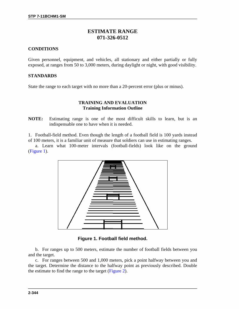
STP 7-11BCHM1-SM
2-344
ESTIMATE RANGE 071-326-0512
CONDITIONS Given personnel, equipment, and vehicles, all stationary and either partially or fully exposed, at ranges from 50 to 3,000 meters, during daylight or night, with good visibility. STANDARDS State the range to each target with no more than a 20-percent error (plus or minus).
TRAINING AND EVALUATION Training Information Outline
NOTE: Estimating range is one of the most difficult skills to learn, but is an
indispensable one to have when it is needed. 1. Football-field method. Even though the length of a football field is 100 yards instead of 100 meters, it is a familiar unit of measure that soldiers can use in estimating ranges. a. Learn what 100-meter intervals (football-fields) look like on the ground (Figure 1).
Figure 1. Football field method.
b. For ranges up to 500 meters, estimate the number of football fields between you and the target. c. For ranges between 500 and 1,000 meters, pick a point halfway between you and the target. Determine the distance to the halfway point as previously described. Double the estimate to find the range to the target (Figure 2).

STP 7-11BCHM1-SM
2-345
TARGET HALFWAYPOINT
Figure 2. Halfway-point method.
d. Learn the effects of terrain and weather conditions on target appearance (Figure 3).
CONDITIONS IN WHICHTARGETS SEEM CLOSER
CONDITIONS IN WHICHTARGETS SEEM FARTHER AWAY
Bright, clear, daylight conditions Foggy, rainy, hazy, or twilight conditions
Targets with sun in front of them Targets with sun behind them
Targets at higher elevations Targets at lower elevations
Large targets Small targets
Brightly colored targets(white, red, yellow)
Darkly colored targets
Targets that have contrast Camouflaged targets
Targets viewed across a ravine,hollow, river, or depression
Targets at sea
Figure 3. Effects of terrain and weather on target appearance.

STP 7-11BCHM1-SM
2-346
2. Recognition/appearance-of-objects method. a. Although the target conditions in Figure 4 will have some effect on range estimation, the data in Figure 4 generally hold true. b. If possible, study the appearance of people and objects at various distances until you know how far away they are by how big or clear they seem to be.
TARGET
DISTANCE TARGET CANBE RECOGNIZEDWITH THE NAKED EYE(in meters)
DISTANCE TARGET CANBE RECOGNIZEDWITH BINOCULARS(in meters)
A tank crew member,soldier, machine gun,mortar, antitank gun,antitank missile launcher
500 2,000
Tank, armoredpersonnel carrier, truck(by model)
1,000 4,000
Tank, howitzer, armoredpersonnel carrier, truck
1,500 5,000
Armored or wheeledvehicle
2,000 6,000
Figure 4. Target recognition method.
3. Flash-to-bang method. a. Using this method, determine range by measuring the time between the flash and the gun report (Figure 5). Sound travels at the speed of 330 meters per second. Light travels much faster. b. Observe the flash of the target or weapon firing. c. Count the number of seconds until you hear the weapon fire. You may measure this time interval on a stopwatch, or you may estimate it by counting steadily. For example, a 3-second count would be “one-thousand-one, one-thousand-two, one-thousand-three” or “1 and 2 and 3.” If you must count higher than 10, start over at 1. d. Multiply the number of seconds by 330 meters (the speed of sound) to estimate the range from your position to the target.
EXAMPLE: You should be able to identify armored and wheeled vehiclesfrom 1,500 to 2,000 meters with the naked eye. If you can identify thevehicle as a tank, but you cannot determine the model, the range is between1,000 and 1,500 meters. Binoculars greatly increase the range at which youcan identify your target.

STP 7-11BCHM1-SM
2-347
1 AND 2 AND...
SEE THE FLASH OR DUST—STOP COUNTING
HEAR THE REPORT—STOP COUNTING
3 AND 4 AND 5
1 AND 2 AND... 3 AND 4 AND 5
HEAR THE REPORT—STOP COUNTING
SEE THE FLASH—START COUNTING
DURING DARKNESS
DURING DAYLIGHT
Figure 5. Flash-to-bang method.
4. Binocular-reticle/mil-relation methods. a. Binocular-reticle method. Fire control equipment requires precise calculations and adjustments, so it is marked in mils. You can use the reticle in a pair of binoculars to determine the width, length, or height of a target in mils (Figure 6).

STP 7-11BCHM1-SM
2-348
12345 5420
10
05
21
5 MILS
2 MILS
10 MILS
Figure 6. Binocular reticle.
b. Mil-relation method. Use the width, length, or height of the target in mils, represented by the R in the mil-relation formula, R = W – m, to determine the range to the target (Figure 7). The mil relation holds true whether the W is measured horizontally or vertically (Figure 8).
1,000 METERS
2 m1 m
Figure 7. Mil-relation method.
m
mm
m
R
R R
R
Figure 8. Use of the mil-relation formula.
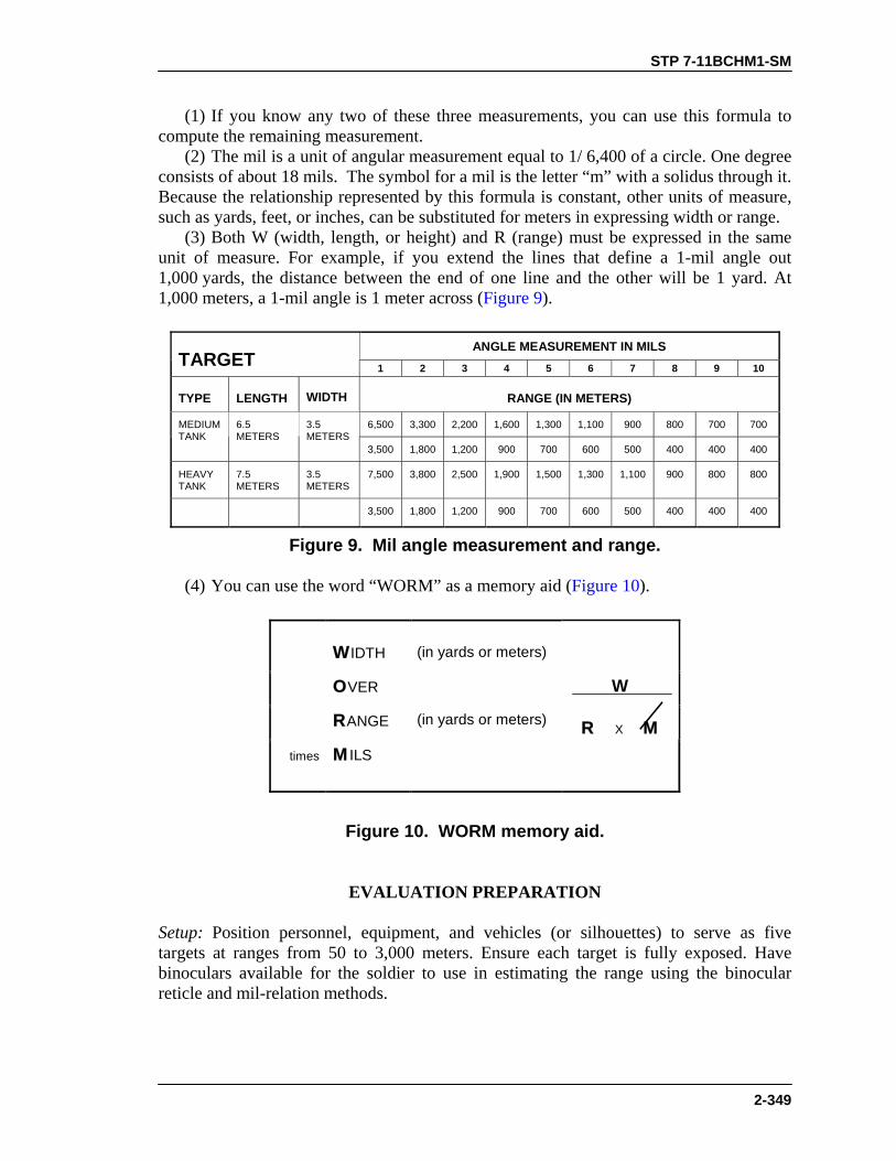
STP 7-11BCHM1-SM
2-349
(1) If you know any two of these three measurements, you can use this formula to compute the remaining measurement. (2) The mil is a unit of angular measurement equal to 1/ 6,400 of a circle. One degree consists of about 18 mils. The symbol for a mil is the letter “m” with a solidus through it. Because the relationship represented by this formula is constant, other units of measure, such as yards, feet, or inches, can be substituted for meters in expressing width or range. (3) Both W (width, length, or height) and R (range) must be expressed in the same unit of measure. For example, if you extend the lines that define a 1-mil angle out 1,000 yards, the distance between the end of one line and the other will be 1 yard. At 1,000 meters, a 1-mil angle is 1 meter across (Figure 9).
ANGLE MEASUREMENT IN MILSTARGET 1 2 3 4 5 6 7 8 9 10
TYPE LENGTH WIDTH RANGE (IN METERS)
6,500 3,300 2,200 1,600 1,300 1,100 900 800 700 700MEDIUMTANK
6.5METERS
3.5METERS
3,500 1,800 1,200 900 700 600 500 400 400 400
HEAVYTANK
7.5METERS
3.5METERS
7,500 3,800 2,500 1,900 1,500 1,300 1,100 900 800 800
3,500 1,800 1,200 900 700 600 500 400 400 400
Figure 9. Mil angle measurement and range.
(4) You can use the word “WORM” as a memory aid (Figure 10).
WIDTH (in yards or meters)
OVER
RANGE (in yards or meters)
times MILS
W
R X M
Figure 10. WORM memory aid.
EVALUATION PREPARATION
Setup: Position personnel, equipment, and vehicles (or silhouettes) to serve as five targets at ranges from 50 to 3,000 meters. Ensure each target is fully exposed. Have binoculars available for the soldier to use in estimating the range using the binocular reticle and mil-relation methods.

STP 7-11BCHM1-SM
2-350
Brief Soldier: Tell the soldier that he must state the distance to at least three of the five targets, with no more than 20 percent error in the distance he states to each.
EVALUATION GUIDE
Performance Measures
Results
1. Using football field method.
P F
2. Using recognition/appearance-of-objects method.
P F
3. Using flash-to-bang method.
P F
4. Using binocular-reticle/mil-relation method. P F
FEEDBACK
If the soldier passes all steps, score him GO. If he fails any steps, score him NO-GO, then show him what he did wrong and how to do it correctly.
REFERENCES Required Related None FM 17-12 FM 21-75
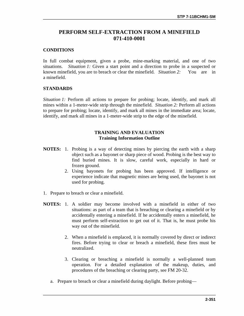
STP 7-11BCHM1-SM
2-351
PERFORM SELF-EXTRACTION FROM A MINEFIELD 071-410-0001
CONDITIONS In full combat equipment, given a probe, mine-marking material, and one of two situations. Situation 1: Given a start point and a direction to probe in a suspected or known minefield, you are to breach or clear the minefield. Situation 2: You are in a minefield. STANDARDS Situation 1: Perform all actions to prepare for probing; locate, identify, and mark all mines within a 1-meter-wide strip through the minefield. Situation 2: Perform all actions to prepare for probing; locate, identify, and mark all mines in the immediate area; locate, identify, and mark all mines in a 1-meter-wide strip to the edge of the minefield.
TRAINING AND EVALUATION Training Information Outline
NOTES: 1. Probing is a way of detecting mines by piercing the earth with a sharp
object such as a bayonet or sharp piece of wood. Probing is the best way to find buried mines. It is slow, careful work, especially in hard or frozen ground.
2. Using bayonets for probing has been approved. If intelligence or experience indicate that magnetic mines are being used, the bayonet is not used for probing.
1. Prepare to breach or clear a minefield. NOTES: 1. A soldier may become involved with a minefield in either of two
situations: as part of a team that is breaching or clearing a minefield or by accidentally entering a minefield. If he accidentally enters a minefield, he must perform self-extraction to get out of it. That is, he must probe his way out of the minefield.
2. When a minefield is emplaced, it is normally covered by direct or indirect
fires. Before trying to clear or breach a minefield, these fires must be neutralized.
3. Clearing or breaching a minefield is normally a well-planned team
operation. For a detailed explanation of the makeup, duties, and procedures of the breaching or clearing party, see FM 20-32.
a. Prepare to breach or clear a minefield during daylight. Before probing—

STP 7-11BCHM1-SM
2-352
(1) Remove items, such as packs, rucksacks, helmets, and web gear, and leave them in a designated area. (2) Remove jewelry and place it in pockets, or leave it with the web gear. (3) Keep the individual weapon, protective mask, and flak jacket. Sling the rifle across the back and wear the mask in the leg-carry position. (4) Keep dog tags around the neck and tucked inside the shirt. (5) Remove the field jacket and roll the sleeves above the elbows so that trip wires may be felt more easily. If the weather conditions demand that field jackets or heavy outer garments be worn, use extra caution in feeling for trip wires. b. Get into position to probe. Approach the start point, which has been determined by the OIC or NCOIC. (1) If the area to be probed is open terrain and is free of brush or trees, stand facing the strip to be cleared and visually inspect the area immediately to the front for trip wires. (2) Slowly ease into a full squat. Feel from the height of any grass or short vegetation to the ground to ensure no trip wires have been hidden in the grass. (3) Stay behind the probe starting point. Move from the full squat into a kneeling position. To go into a kneeling position, slide one foot to the rear and place the knee where the foot was. To kneel on both knees, repeat this procedure with the other foot. Probing can be done on one or both knees, whichever is more comfortable. NOTE: When required by the tactical situation, probing can be done from the prone
position. From the kneeling position, slide each foot to the rear to obtain the full prone position.
(4) If the area to be probed is covered by brush or trees, stand facing the strip to be cleared and visually inspect the area immediately to the front for trip wires. (5) Raise arms up along the sides until fully extended over the head, palms to the front. Bring the arms slowly down to the front, feeling for trip wires, until the arms are straight to the front. Keep the arms extended to the front and slowly ease into a full squat, again feeling for trip wires with the hands and arms. Once in a full squat, continue to feel for trip wires with the hands and arms down to ground level. (6) From the full squat, go into the kneeling position as explained above.
CAUTIONWhile working in an area with brush or trees, continually observeoverhead for trip wires while moving forward.
(7) Probing may begin from this position. c. Prepare to clear mines during limited visibility. The same procedures are used for preparation and for entering the kneeling or prone position in darkness, fog, or smoke as are used in daylight in a brush or tree-covered area. d. Perform self-extraction from minefields.

STP 7-11BCHM1-SM
2-353
NOTE: Normally, the first indication that you are in a minefield is when someone sets off a mine. Upon hearing or seeing an explosion, the natural reaction is to “hit the dirt,” then determine if it was incoming indirect fire, a booby trap, or a mine. Each individual must determine whether “hitting the dirt” or “freezing in place” is safer.
(1) When a mine has been detected without being set off and the alert of, “Mines,” is given, “freeze in place.” (2) After determining that you are in a minefield and the minefield is not covered by fire, proceed as follows: (a) Whether in the prone position or still standing, examine the ground, bushes, and trees present. Look between, around, or under the feet or knees, or around and under the body. (b) Using the bayonet, probe to clear an area large enough to move in. (c) Remove all equipment and bundle it together. (d) Normally, clear out of the minefield along the same path used to enter it. (e) If forward movement is required, clear a lane. If others are close, clear a path to a central point. From there, clear a single lane to be used by the group. Coming together increases morale and allows rotation of the probers. Ensure that a safe distance is maintained between the one probing and the rest of the group. (f) Do not leave equipment. Once it is bundled together, drag it along while probing out of the minefield. (3) If the minefield is covered by fire, perform all probing from the prone position. (a) All personnel stay separated. (b) Removing or keeping equipment on is a decision that has to be made based on the situation. (c) Each individual is on his own to self-extract himself in the fastest and safest manner possible, either out of the minefield or to the nearest covered position from which to return fire. 2. Probe for mines. a. After looking and feeling, hold the probe in the hand (palm up) and probe every 2 inches across a 1-meter front. Push the probe gently into the ground at an angle less than 45 degrees from the horizontal, putting just enough pressure on the probe to sink it slowly into the ground (Figure 1).

STP 7-11BCHM1-SM
2-354
Figure 1. Probing.
WARNINGIf pushed straight down, the tip of the probe may detonate apressure mine.
b. If the probe does not go into the ground freely, pick or chip away the soil using the tip of the probe, and remove the loose dirt by hand. c. When a solid object is touched, stop probing and remove enough dirt to identify the object. d. If a mine is found, remove enough dirt to show the type of mine, then mark and report its exact location to the next in command. NOTE: After probing across the 1-meter front, move the probe forward 2 inches and
probe across the 1-meter front again. Continue this procedure until the minefield has been breached.
3. Mark mines. During breaching or self-extraction, clearly mark detected mines so that friendly troops can safely bypass them. Do this by placing a stick with cloth attached near the mine, a tripod of sticks over the mine, or a ring of rocks around the mine; or by at least uncovering enough of the mine so that it can be seen easily. Use any method of marking as long as it is known by all soldiers.

STP 7-11BCHM1-SM
2-355
EVALUATION PREPARATION Situation 1, Breaching or Clearing. Setup: Breach or clear—
• Open or grass-covered terrain. Prepare a lane 1-meter wide. Include at
least two mines within the lane. Mines may be antitank and antipersonnel or antipersonnel only. The first mine should not be more than 6 to 9 inches from the start point. In grass-covered terrain, hide one trip wire in the grass. The length of the lane depends on the time available for testing.
• Brush or tree-covered terrain. Prepare a lane 1-meter wide. Include at
least two antipersonnel mines within the lane. The first mine should not be more than 6 to 9 inches from the start point. Include one trip wire at ankle level near the start point and one trip wire at waist level 5 to 6 feet from the start point. The length of the lane depends on the time available for testing.
Brief Soldier: Breaching or clearing. Tell the soldier the start point and
the direction to probe. Tell him to identify by type every mine he finds and mark them.
Situation 2, Self Extraction. Setup: Prepare an area 2 meters square. Include a minimum of nine
dummy mines within the square. Mark a point in the center. Ensure at least one mine is 18 inches from the marked center point. Wear full combat equipment.
NOTE: Tin cans can be used to simulate mines if dummy mines are not
available. When using tin cans, the soldier is not required to identify mines as to type.
Brief Soldier: Tell the soldier he will administratively move to the marked
center point in the square. Tell the soldier to wear all combat equipment to start the self-extraction. Tell the soldier he will be given the alert, “Mines,” and he will perform a self-extraction to the edge of the square. Tell the soldier the direction of the enemy side of the minefield.

STP 7-11BCHM1-SM
2-356
EVALUATION GUIDE
Performance Measures
Results
1. Breach or clear minefields. a. Prepare for probing. (1) Remove equipment.
P F
(2) Remove jewelry. (3) Roll sleeves above elbows (weather permitting). (4) Sling the rifle across the back. (5) Retain the protective mask in the leg-carrying position.
b. Probing position. (1) Assume the position for open terrain.
(2) Assume the position for terrain with brush or trees. (3) Assume the position for limited visibility. c. Probing. (1) Hold the probe.
(2) Probe. (3) Mark the mine(s). (4) Identify the type of mine(s).
2. Self-extraction. a. Probe an area large enough to move in (about 1 meter in diameter).
P F
b. Remove equipment. c. Prepare equipment. d. Hold the probe. e. Probe. f. Mark the mine(s).
FEEDBACK
If the soldier passes all steps, score him GO. If he fails any steps, score him NO-GO, then show him what he did wrong and how to do it correctly.
REFERENCES
Required Related None FM 20-32

STP 7-11BCHM1-SM
2-357
MOUT
SELECT HASTY FIRING POSITIONS DURING MOUT 071-326-0557
CONDITIONS As a member of an attacking or defending unit in urban terrain. STANDARDS Select positions from which to place fire on the enemy while using available cover.
TRAINING AND EVALUATION
Training Information Outline NOTE: The success of the mission depends on the ability to place accurate fire on the
enemy with the least possible exposure to return fire. Therefore, constantly seek covered firing positions and use them properly.
1. Fire around a building or wall. a. Use the left-handed firing technique to fire around the left corner of a building or wall (Figure 1).
Figure 1. Firing around the left corner of a building.
b. Use the right-handed firing technique to fire around the right corner of a building or wall (Figure 2).

STP 7-11BCHM1-SM
2-358
Figure 2. Firing around the right corner of a building.
c. Use the prone firing technique when possible. d. Fire around a wall when possible, not over it (Figure 3).
Figure 3. Firing around a wall.
2. Fire from a window. a. Select firing positions that are well back from the window. They help conceal the body and the rifle’s muzzle. b. Select a kneeling firing position to minimize exposure and prevent silhouetting (Figure 4).

STP 7-11BCHM1-SM
2-359
Figure 4. Firing from a window.
3. Fire from unprepared loopholes. Select firing positions that are well back from the loophole to conceal the muzzle flash (Figure 5).
NO MUZZLE FLASHVISIBLE FROM
OUTSIDE
NO MUZZLE FLASH
FIRING FROM DEEPERINSIDE BUILDING
Figure 5. Firing from loophole.
EVALUATION PREPARATION Setup: At the test site, provide all the materials and equipment given in the task conditions statement. Brief Soldier: Tell the soldier to select positions from which he can place fire on the enemy while using available cover.

STP 7-11BCHM1-SM
2-360
EVALUATION GUIDE Performance Measures
Results
1. Fires around a building or wall. a. Uses the left corner. b. Uses the right corner. c. Uses the prone firing technique, when possible. d. Fires around (not over) a wall, when possible.
P F
2. Fires from a window. a. Selects a position well back from the window. b. Uses a kneeling firing position.
P F
3. Fires from unprepared loopholes. Selects a position well back fromthe window.
P F
FEEDBACK
If the soldier passes all steps, score him GO. If he fails any steps, score him NO-GO, then show him what he did wrong and how to do it correctly.
REFERENCES
Required Related FM 90-10-1 None
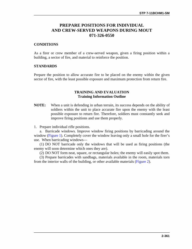
STP 7-11BCHM1-SM
2-361
PREPARE POSITIONS FOR INDIVIDUAL AND CREW-SERVED WEAPONS DURING MOUT
071-326-0550 CONDITIONS As a firer or crew member of a crew-served weapon, given a firing position within a building, a sector of fire, and material to reinforce the position. STANDARDS Prepare the position to allow accurate fire to be placed on the enemy within the given sector of fire, with the least possible exposure and maximum protection from return fire.
TRAINING AND EVALUATION Training Information Outline
NOTE: When a unit is defending in urban terrain, its success depends on the ability of
soldiers within the unit to place accurate fire upon the enemy with the least possible exposure to return fire. Therefore, soldiers must constantly seek and improve firing positions and use them properly.
1. Prepare individual rifle positions. a. Barricade windows. Improve window firing positions by barricading around the window (Figure 1). Completely cover the window leaving only a small hole for the firer’s use. When barricading windows— (1) DO NOT barricade only the windows that will be used as firing positions (the enemy will soon determine which ones they are). (2) DO NOT form neat, square, or rectangular holes; the enemy will easily spot them. (3) Prepare barricades with sandbags, materials available in the room, materials torn from the interior walls of the building, or other available materials (Figure 2).

STP 7-11BCHM1-SM
2-362
MUZZLE SHOULDNOT PROTRUDEBEYOND WINDOW
WINDOW POSITION
WIREMESH
Figure 1. Barricaded window.
Figure 2. Barricaded firing position.
NOTE: Do not remove so much material from interior walls that the building is weakened.
(4) Remove all glass from the window to prevent injury from flying glass. (5) Leave curtains in place—they let the firer see out and prevent the enemy from seeing in. (6) Place a wet blanket over dusty surfaces in front of the weapon’s muzzle or wet down those surfaces to prevent dust from the muzzle blast from revealing the position (Figure 3).
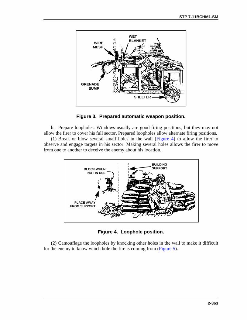
STP 7-11BCHM1-SM
2-363
WIREMESH
WETBLANKET
SHELTER
GRENADESUMP
Figure 3. Prepared automatic weapon position.
b. Prepare loopholes. Windows usually are good firing positions, but they may not allow the firer to cover his full sector. Prepared loopholes allow alternate firing positions. (1) Break or blow several small holes in the wall (Figure 4) to allow the firer to observe and engage targets in his sector. Making several holes allows the firer to move from one to another to deceive the enemy about his location.
BLOCK WHENNOT IN USE
BUILDINGSUPPORT
PLACE AWAYFROM SUPPORT
Figure 4. Loophole position.
(2) Camouflage the loopholes by knocking other holes in the wall to make it difficult for the enemy to know which hole the fire is coming from (Figure 5).

STP 7-11BCHM1-SM
2-364
MISSING ORREMOVEDROOFTILE
CHIMNEYS
WALL
CUTAWAYVIEW
CONCEALEDUNDEREAVES
IN BOTTOMOF DOORS
BEHINDBUSHES
INVENTS
SHUTTERS
BEHIND VINES
Figure 5. Camouflage of loopholes.
(3) Use sandbags or other material to reinforce the walls around loopholes (Figure 6).

STP 7-11BCHM1-SM
2-365
Figure 6. Reinforced loopholes. (4) When reinforcing windows or loopholes, the firer places two layers of sandbags on the floor under him. This protects him from an explosion on a lower floor when the position is on the second floor or higher. He can use tables, bedsteads, or other available material to provide overhead cover from falling debris or from explosions above the position. A blast wall can be built to the rear of the position to protect the firer from explosions in the room (Figure 7).
ESCAPEROUTE
AT LEAST TWO LAYERS OFSANDBAGS ON TOP, FRONT,REAR, SIDES, AND UNDERSIDE
LINE OF SIGHTTABLE
Figure 7. Reinforced position.
c. Preparer sniper positions. (1) Sniper positions should be on or near the top of the building being defended to allow greater fields of fire (Figure 8).

STP 7-11BCHM1-SM
2-366
COVERROOFS
COVERGAPSIN FPF
COVER DEADSPACE
COVEROBSTACLES
COVER DEADSPACE
Figure 8. Sniper positions.
(2) A chimney or other structure protruding through the roof of a building provides a base from which a sniper position can be prepared. Part of the roofing material is removed to allow the sniper to fire around the chimney while standing below roof level on a constructed platform with only his head and shoulders above the roof. (3) Sandbags may be used on the sides of the position to protect the sniper’s flanks. 2. Prepare machine gun positions. a. The machine gun can be emplaced in the same type of position as the individual individual firer, except that windows or doors should be avoided. Windows and doors are where the enemy expects machine guns to be emplaced, therefore they draw the most fire. Because machine guns are not as mobile as rifles, they cannot move as quickly to avoid heavy fires. b. Emplace machine guns as low as possible, using loopholes behind shrubbery or under doorjambs. Basement windows can also be used. By placing the machine gun at a lower level, grazing fire is obtained (Figure 9).

STP 7-11BCHM1-SM
2-367
Figure 9. Low machine gun position.
c. Although grazing fire is desirable when employing the machine gun, it is impractical or impossible where destroyed vehicles, rubble, and other obstructions restrict the field of grazing fire. In such cases, emplace the machine gun at a higher location and fire from loopholes on the second or third floor, or fire through a loophole in the roof (Figure 10).
Figure 10. High machine gun position.
3. Prepare antitank weapons position. Training safety instructions from the field manuals for each weapon must be strictly followed. a. Position antitank weapons (TOW, Dragon, 90-mm, LAW, AT4) on upper stories for long-range coverage (Figure 11).

STP 7-11BCHM1-SM
2-368
Figure 11. Antitank weapons placement.
NOTE: The maximum depression and elevation limits of the TOW mount plus the minimum firing distance (65 meters) may result in dead space and preclude the engagement of close-in targets.
b. Backblast must be considered in choosing and preparing an antitank weapon location. None of the antitank weapons can be fired from an unvented or enclosed room (Figure 12, Figure 13, and Figure 14). When the temperature drops below freezing, all backblast areas double in size. Leaders must ensure the backblast misses other positions. For more exact backblast information, refer to the chapter or appendix entitled “Safety” in the weapon’s respective field manuals.
Figure 12. TOW position.

STP 7-11BCHM1-SM
2-369
Figure 13. Dragon position.
Figure 14. LAW position.
c. Avoid firing from inside a building. When firing from inside a building cannot be avoided, the following conditions must be met before firing: (1) The building must be sturdy. (2) The ceiling must be at 7least 8 feet high. (3) The floor size of the room must be at least 17 by 24 feet for a TOW or AT4, 12 by 15 feet for a Dragon, and 4 feet to the back wall for a LAW backblast area.

STP 7-11BCHM1-SM
2-370
(4) In addition, an opening at least 20 feet square must be at the rear of the weapon for backblast. An open 7- by 3-foot door is adequate, but it must be located directly behind the firer. (5) All glass must be removed from windows beside and behind the weapon; windows and doors on the firing wall must be reinforced only, to avoid drawing attention to them. Reinforcing the windows also helps protect soldiers from direct fire. All loose objects must be removed from the room. (6) All soldiers within the room must be forward of the rear of the weapon and must avoid standing in corners or near walls. If possible, they should construct reinforced positions that can protect them in case the building collapses. (7) All soldiers in the room must protect their ears when the weapon is fired. (8) The clearance between the muzzle of the weapon and the opening it is fired from should be 9 inches for a TOW, 6 inches for a Dragon and for an M136 AT4. d. When emplacing the TOW and Dragon, the 65-meter minimum firing distance (arming distance) must be considered. e. Antitank weapon positions should be reinforced the same as the individual rifle position, except that no blast wall is erected.
EVALUATION PREPARATION Setup: At the test site, provide all the materials and equipment given in the task conditions statement. Brief Soldier: Tell the soldier to prepare an individual or crew-served weapon position.
EVALUATION GUIDE
Performance Measures
Results
1. Prepares individual rifle positions. a. Barricades the windows.
P F
b. Prepares and camouflages the loopholes. c. Prepares sniper positions.
2. Preparers the machine gun positions. a. Avoids doors and windows.
P F
b. Emplaces as low as possible for grazing fire. c. If field of grazing fire is obstructed, emplaces higher.

STP 7-11BCHM1-SM
2-371
EVALUATION GUIDE
Performance Measures
Results
3. Prepares the antitank weapon positions. a. Positions the weapons on the upper stories.
P F
b. Identifies the backblast area. c. Ensures that the building is structurally sound and canwithstand firing.
d. Identifies minimum firing distance for the TOW and Dragon. e. Reinforces the position.
FEEDBACK
If the soldier passes all steps, score him GO. If he fails any steps, score him NO-GO, then show him what he did wrong and how to do it correctly.
REFERENCES Required Related FM 90-10 None FM 90-10-1
STP 7-11BCHM1-SM
2-372
PERFORM MOVEMENT TECHNIQUES DURING MOUT 071-326-0541
CONDITIONS As a member of an assault element in urban terrain with the enemy location and strength uncertain, given an individual weapon with ammunition and load-bearing equipment. STANDARDS Perform a visual reconnaissance to determine the next position; then, using proper movement techniques, move rapidly to the next covered or concealed position with minimum exposure to enemy fire.
TRAINING AND EVALUATION Training Information Outline
NOTES: • Individual, fire team, and squad movement techniques within urban terrain
differ slightly from the basic movements used in normal field operations. Several movement techniques take on added importance during combat in urban terrain because of the special nature of the battle area.
• In an urban terrain, the individual soldier and leaders are confronted with
different types of obstacles that must be negotiated to eliminate or capture an enemy position. Street-to-street and house-to-house fighting give rise to many surprising situations, so alertness and all-round security are mandatory. The enemy may appear not only from the front, flanks, and rear, but also from above and below.
1. Follow general rules of movement: a. Take care not to be silhouetted in doors or windows, or on rooftops. b. Avoid open areas (streets, alleys, parks). c. Make a visual reconnaissance of the next position before moving. d. Conceal movement with smoke or covering fires, and by using buildings, rubble, and vegetation. e. Always move quickly from one position to another. f. Be alert and expect the unexpected. 2. Observe around corners. a. Lie flat on the ground, weapon at the side, then move forward slowly, ensuring that the weapon is not forward of the corner.

STP 7-11BCHM1-SM
2-373
NOTE: Corners are hazardous to untrained soldiers who are not alert. The most common mistakes untrained soldiers make are: first, not recognizing the danger area; second, extending their weapons beyond the corner, which exposes their presence; and third, showing their heads at a height that enemy soldiers would expect to see them.
b. Expose the head slowly at ground level so that it appears to be a shadow. Expose the head only enough to observe around the corner (Figure 1).
Figure 1. Observing around a corner.
3. Move across open areas. NOTE: Open areas, such as streets, alleys, and parks, should be avoided when
possible. They are natural kill zones for enemy crew-served weapons. They can be crossed with less risk if basic cautions are applied.
a. Make a visual reconnaissance of the area and position. b. Select a route that has some cover or concealment. If no cover or concealment is available, use smoke or covering fire provided by the rest of the element. c. Move in the most direct route to the selected position. Using the most direct route reduces the time of exposure to enemy fire. Also, moving quickly denies the enemy the opportunity to place well-aimed shots. d. Move from position to position without masking covering fires. When the next position is reached, be prepared to cover the movement of other members of the fire team or squad (Figure 2).

STP 7-11BCHM1-SM
2-374
Figure 2. Moving from cover to cover.
e. When two or more soldiers must move at the same time to another position— (1) The group members must first position themselves so they are prepared to move to their next position. (2) On a planned signal, the group members move across the open area to the next position. When moving, they should stay about 5 meters apart (Figure 3).
Figure 3. Group moving to the next position.

STP 7-11BCHM1-SM
2-375
4. Move parallel to buildings. a. Move along the walls. When moving parallel to a building, move along the wall as closely as possible. That denies an enemy soldier inside the building the chance to fire without exposing himself to fire from the covering force. (1) Use all available cover and concealment, move with a low silhouette, and advance quickly from position to position. If smoke is available, use it. (2) When possible, move in the shadows to conceal movement. b. Move past the first floor windows. NOTE: Windows are danger points. Most first-floor windows are head high, and an
unsuspecting soldier might expose his head, giving the concealed enemy an excellent shot.
(1) The right way to pass first-floor windows is to stay as close to the building as possible. When the window is reached, duck the head well below the window. (2) Always take care not to be silhouetted in a window (Figure 4).
Figure 4. Movement past window.
c. Move past the basement windows. (1) Do not merely walk or run past a basement window; your legs will present a good target to an enemy gunner inside the building. (2) The right way to pass a basement window is to keep as close to the building as possible and, when you reach the window, step or jump above and pass the window without exposing your legs (Figure 5 and Figure 6).

STP 7-11BCHM1-SM
2-376
Figure 5. Start of movement past basement window.
Figure 6. Completion of movement past basement.
5. Cross obstacles (walls, fences, rooftops). a. Move over walls and fences. (1) Before crossing a wall or fence, look at and beyond it for booby traps, enemy positions, and covered or concealed positions. (2) Move rapidly to the obstacle and roll quickly over it, keeping the lowest silhouette possible. Speed and a low silhouette deny the enemy a well-aimed shot. (3) Maintaining a low silhouette, with the weapon at the ready position, move quickly to the nearest position (Figure 7).

STP 7-11BCHM1-SM
2-377
Figure 7. Crossing of an obstacle.
b. Move over rooftops. (1) Visually reconnoiter the area and the route to the next position. (2) Move quickly across the area, maintaining a low silhouette and using all available cover and concealment.
EVALUATION PREPARATION Setup: At the test site, provide all materials and equipment given in the task conditions statement. Brief Soldier: Tell the soldier that he will be moving as a designated member of an assault element in urban terrain. The enemy strength and location are unknown.
EVALUATION GUIDE
Performance Measures
Results
1. Follow the general rules of movement. a. Do not silhouette self.
P F
b. Avoid open areas. c. Make visual reconnaissance of the next position before moving. d. Conceal movement. e. Move rapidly. f. Stay alert.
2. Observe around corners. a. Lay flat, weapon at side; move forward slowly. b. Expose head slowly, at ground level, only long enough to observearound the corner.
P F

STP 7-11BCHM1-SM
2-378
EVALUATION GUIDE
Performance Measures
Results
3. Move across open areas. a. Visually reconnoiter area and position.
P F
b. Select route with cover and concealment. c. Move in the most direct route. d. Move from position to position without masking covering fires. e. When two (or more) soldiers must move to the same position atthe same time they— (1) Position themselves to prepare to move together.
(2) Move together at a planned signal. (3) Stay about 5 meters apart.
4. Move parallel to the buildings. a. Move along the walls. (1) Move close to and parallel to the wall.
P F
(2) Move rapidly with a low silhouette. (3) Move in shadows when possible.
b. Move past the first floor windows. (1) Stay close to the building; keep head below window. (2) Do not silhouette self in window.
c. Move past the basement windows. d. Step or jump over windows.
5. Cross obstacles. a. Move over walls or fences. (1) Check the obstacle for booby traps, enemy positions, and coveredand concealed positions.
P F
(2) Move quickly to the obstacle and quickly roll over it; maintain alow silhouette.
(3) Move quickly to the nearest position; maintain a low silhouette. b. Move over rooftops. (1) Make a visual reconnaissance of the area and route. (2) Move quickly across the area, maintain a low silhouette, and use all available cover.
FEEDBACK
If the soldier passes all steps, score him GO. If he fails any steps, score him NO-GO, then show him what he did wrong and how to do it correctly.

STP 7-11BCHM1-SM
2-379
REFERENCES
Required Related None FM 90-10-1

STP 7-11BCHM1-SM
2-380
SUSTAIN, GENERAL
PRACTICE PREVENTIVE MEDICINE 081-831-1043
CONDITIONS Squad is participating in a road march, operation, or movement. STANDARDS Before and during the conduct of the mission, care for the feet before and during the march or movement; use iodine tablets to purify water; properly dispose of human waste IAW unit SOP or guidance from higher headquarters; and prevent or respond correctly to heat and cold injuries.
TRAINING AND EVALUATION Training Information Outline
1. Care of the feet. a. Before the march, be sure footgear is the proper type, is correctly fitted, and is broken in; that socks are clean and free of holes or knotty darns; and that you have foot powder and more than one pair of socks. Never break in a new pair of shoes or boots on a march. Treat and protect blisters (Figure 1), pressure spots, and infections before the march starts.
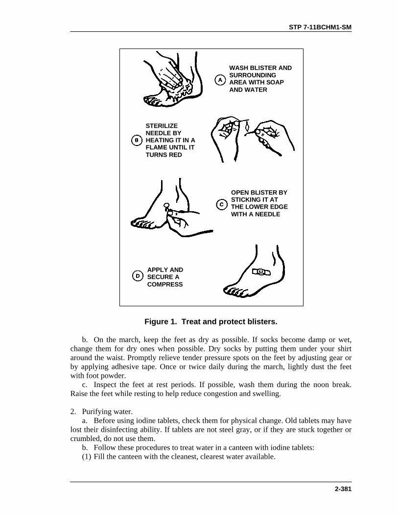
STP 7-11BCHM1-SM
2-381
WASH BLISTER ANDSURROUNDINGAREA WITH SOAPAND WATER
STERILIZENEEDLE BYHEATING IT IN AFLAME UNTIL ITTURNS RED
OPEN BLISTER BYSTICKING IT ATTHE LOWER EDGEWITH A NEEDLE
APPLY ANDSECURE ACOMPRESS
Figure 1. Treat and protect blisters.
b. On the march, keep the feet as dry as possible. If socks become damp or wet, change them for dry ones when possible. Dry socks by putting them under your shirt around the waist. Promptly relieve tender pressure spots on the feet by adjusting gear or by applying adhesive tape. Once or twice daily during the march, lightly dust the feet with foot powder. c. Inspect the feet at rest periods. If possible, wash them during the noon break. Raise the feet while resting to help reduce congestion and swelling. 2. Purifying water. a. Before using iodine tablets, check them for physical change. Old tablets may have lost their disinfecting ability. If tablets are not steel gray, or if they are stuck together or crumbled, do not use them. b. Follow these procedures to treat water in a canteen with iodine tablets: (1) Fill the canteen with the cleanest, clearest water available.

STP 7-11BCHM1-SM
2-382
(2) Add one iodine tablet to a 1-quart canteen if the water is clear; add two tablets if the water is cloudy. Double the amounts for a 2-quart canteen. (3) Place the cap on the canteen loosely, wait 5 minutes, and shake the canteen well. Allow leakage to rinse the threads around the neck of the canteen. (4) Tighten the cap and wait 20 minutes more before using the water. 3. Disposing of human solid waste, except when unit SOP or higher headquarters provides other specifications. a. When on the march, use an individual cathole latrine during short halts. Dig it about 1 foot deep. Completely cover and pack it down after use. b. For overnight bivouac, use the straddle trench (Figure 2). Building details are given in FM 21-10.
CAN OFWATER
SOAKAGEPIT
SHOVEL ANDEXCAVATED
DIRT
PAPER COVEREDWITH A CAN
HAND-WASHINGDEVICE
2' 6" DEEP
4'
2'
Figure 2. Straddle trench.
4. Heat and cold injuries. a. Preventing heat injuries. The soldier should ensure he satisfies his water and salt needs. (1) Water needs. Your body needs a minimum amount of water for cooling, waste elimination, and metabolism. Any attempt to train the body to use less water can be harmful and may lead to heat injuries. Drink water when needed to quench the thirst. (2) Salt needs. When water is lost through sweating, so is vital body salt. When water intake is less than 1 gallon a day, an ordinary diet contains enough salt to make up this loss. If daily water intake increases, lightly salt food from the field rations pack. b. Preventing cold injuries. In cold weather—

STP 7-11BCHM1-SM
2-383
(1) Drinking a sufficient amount of water is as important as it is in hot weather. In cold weather, it is difficult to realize that your body is losing fluids and salt. Sweat evaporates rapidly or is absorbed so completely by the layers of clothing that it is seldom visible on the skin. (2) Clothing for cold weather protects, insulates, and ventilates. It protects by covering the body. It insulates by trapping air that has been warmed by the body and holding it near the skin to prevent loss of body heat. It ventilates by allowing an exchange of air through the various layers of clothing, which prevents overheating and excessive sweating. Clean, dry clothing should be worn in loose layers to allow free movement and exercise. (3) Good circulation should be maintained by exercising the feet and legs. This is important during rest breaks. (4) Troops should be paired as “buddies” in cold weather to remind each other to do warming exercises often and to watch for signs of frostbite and trench foot. FM 21-11 gives signs and first aid for cold-weather injuries. NOTE: FM 21-11 discusses first aid for heat injures.
EVALUATION PREPARATION Setup: In a preselected area before or during a road march, or in a bivouac site, each individual must practice preventive medicine. Brief Soldier: Tell the soldier that he will be evaluated on his ability to properly demonstrate the procedures for foot care before and during a road march, to purify water, to properly dispose of human solid waste (in the absence of unit SOP or guidance from higher headquarters), and to prevent head and cold injuries. NOTE: During training, comply with unit SOP, local regulations, or both concerning
the cutting of live vegetation, digging holes, and preventing erosion.
EVALUATION GUIDE
Performance Measures
Results
1. Properly take care of the feet before the road marches. a. Make sure boots are properly fitted.
P F
b. Make sure boots are broken in (not new boots). c. Wear clean socks, free of holes and knotty darns.
2. Take proper care of the feet during the road marches. a. Keep feet as dry as possible.
P F
b. Change damp socks.

STP 7-11BCHM1-SM
2-384
EVALUATION GUIDE
Performance Measures
Results
c. Dust feet lightly with foot powder. d. Adjust gear or apply adhesive tape to relieve the tender spots on the feet.
3. Purify water with iodine tablets. a. Inspect the iodine tables for a physical change (for example, inspect to ensure tablets are steel gray, and are not crumbled or stuck together).
P F
b. Fill canteen with clean water. c. Add one iodine tablet to a 1-quart canteen filled with clear water. d. Add two iodine tablets to a 2-quart canteen filled with clear water.
e. Add two iodine tablets to a 1-quart canteen filled with cloudy water.
f. Loosely tighten canteen cap and wait five minutes. g. Shake canteen, allowing leakage to rinse the threads around the neck. h. Tighten the cap and wait 20 minutes longer before using.
4. Dispose of human solid waste. a. Dig a cathole (short stops). b. Use the straddle trench (overnight bivouac).
P F
5. Prevent heat injuries (self-evaluation). a. Drink more water than needed to quench thirst. b. When intake of water is more than 1 gallon, slightly increase salt intake.
P F
6. Prevent cold injuries. a. Drink more water than needed to quench thirst.
P F
b. Wear clothing loosely and in layers. c. Pair with a “buddy.”
7. Take care of blisters. a. Wash the blister and surrounding area with soap and water.
P F
b. Sterilize the needle (using a flame). c. Open blister at lower end. d. Apply and secure compress.

STP 7-11BCHM1-SM
2-385
FEEDBACK
If the soldier passes all steps, score him GO. If he fails any steps, score him NO-GO, then show him what he did wrong and how to do it correctly.
REFERENCES Required Related None FM 21-10 FM 21-11

STP 7-11BCHM1-SM
2-386
NBC
MARK NBC CONTAMINATED AREA 031-503-1021
CONDITIONS Given an area where NBC weapons have been used. You are in the appropriate MOPP level. You have NBC markers (radiological, biological, and chemical), grease pencil, information necessary to prepare a marker for each type of contamination, the means to hold the markers in place, and a designated location for the sign. STANDARDS Select the appropriate marker based on information provided, record the required information on the marker, and emplace the marker properly.
TRAINING AND EVALUATION Training Information Outline
1. Once contamination has been located and identified in an area, the area must be marked to warn friendly troops. Markers must be placed where they can be easily seen. a. Radiological contamination. Prepare a marker labeled ATOM. (1) Print all information on the front side of the marker so that the word ATOM is facing toward you in an upright position. (2) Print the dose rate in centigray per hour (cGyph). (3) Print the date and time (local or ZULU, state which). (4) Print the date and time (local or ZULU, state which) of the detonation, if known. (If the date and time is not known, print UNKNOWN.) b. Biological contamination. Prepare a marker labeled BIO. (1) Print all information on the front side of the marker so that the word BIO is facing toward you in an upright position. (2) Print the type of agent detected. (If you do not know, print the word UNKNOWN.) (3) Print the date of detection beneath the type of agent. (4) Print the time (local or ZULU, state which) of detection beneath the date of detection. c. Chemical contamination. Prepare a marker labeled GAS. (1) Print all information on the front side of the marker so that the word GAS is facing toward you in an upright position. (2) Print the type of agent detected. (If you do not know, print the word UNKNOWN.) (3) Print the date and time (local or ZULU, state which) of detection beneath the type of agent detected.

STP 7-11BCHM1-SM
2-387
2. Position the marker so that the recorded information faces away from the area of contamination and the marker can be easily seen. a. Attach the markers to objects, such as trees or poles, so they are clearly visible from all probable routes through the contaminated area. b. Place each marker so that the next one can be seen from the one just emplaced. c. For radiological contamination, place the markers at the location where the dose rate is measured at 1 cGyph or more.
EVALUATION PREPARATION Setup: Simulate a contaminated environment. Before telling the soldier to mark the contaminated area, tell him how much radiation is present. Brief Soldier: Tell the soldier to mark an NBC contaminated area.
EVALUATION GUIDE
Performance Measures
Results
1. Select appropriate marker.
P F
2. Record required information on the marker.
P F
3. Emplace the marker. P F
FEEDBACK
If the soldier passes all steps, score him GO. If he fails any steps, score him NO-GO, then show him what he did wrong and how to do it correctly.
REFERENCES Required Related None FM 3-3 TM 3-9905-001-10
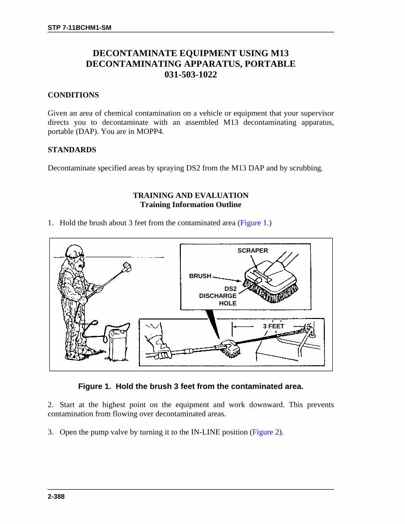
STP 7-11BCHM1-SM
2-388
DECONTAMINATE EQUIPMENT USING M13 DECONTAMINATING APPARATUS, PORTABLE
031-503-1022
CONDITIONS Given an area of chemical contamination on a vehicle or equipment that your supervisor directs you to decontaminate with an assembled M13 decontaminating apparatus, portable (DAP). You are in MOPP4. STANDARDS Decontaminate specified areas by spraying DS2 from the M13 DAP and by scrubbing.
TRAINING AND EVALUATION Training Information Outline
1. Hold the brush about 3 feet from the contaminated area (Figure 1.)
DS2DISCHARGE
HOLE
BRUSH
SCRAPER
3 FEET
Figure 1. Hold the brush 3 feet from the contaminated area.
2. Start at the highest point on the equipment and work downward. This prevents contamination from flowing over decontaminated areas. 3. Open the pump valve by turning it to the IN-LINE position (Figure 2).

STP 7-11BCHM1-SM
2-389
Figure 2. Open pump valve.
4. Pump until DS2 flows from the hole in the brush. 5. Pump one stroke, sweeping an area of 4 to 5 feet while spraying DS2. Close the pump valve. 6. Use the brush to scrub DS2 over contaminated surfaces. 7. Keep repeating steps 1 through 6 until surfaces being decontaminated are wet. 8. Complete steps 1 through 5 in sequence. NOTE: Whenever possible, remove DS2 from decontaminated surfaces after a contact
time of 30 minutes by rinsing with water or wiping with rags.
EVALUATION PREPARATION Setup: Evaluate this task during a field exercise or a normal training session. For test purposes, the soldier must be in MOPP4 with the M13 DAP available and already assembled. and must have a selected piece of equipment or a vehicle that is contaminated. NOTE: You should not use real DS2 during training. Paint a training container black
and fill it with water or a mixture of water and antifreeze to simulate DS2.

STP 7-11BCHM1-SM
2-390
EVALUATION GUIDE
Performance Measures
Results
1. Start at the highest point of the equipment and hold the brush about 3 feet from the contaminated area.
P F
2. Open the pump valve by turning it to the IN-LINE position.
P F
3. Pump one stroke, sweeping an arc of 4 to 5 feet while spraying DS2. Close the pump valve.
P F
4. Use the brush to scrub DS2 over contaminated surface.
P F
5. Repeat performance measures 1 through 4 until surfaces being decontaminated are wet.
P F
NOTE: Whenever possible, after 30 minutes contact time, rinse or wipe off with rags all items that have been sprayed or scrubbed with DS2.
P F
6. Complete performance measures 1 through 5 in sequence. P F
FEEDBACK
If the soldier passes all steps, score him GO. If he fails any steps, score him NO-GO, then show him what he did wrong and how to do it correctly.
REFERENCES
Required Related None FM 3-5 TM 3-4230-214-12&P

STP 7-11BCHM1-SM
2-391
DECONTAMINATE EQUIPMENT USING THE ABC M11 DECONTAMINATING APPARATUS
031-503-2002 CONDITIONS Given an area of chemical contamination on a vehicle or equipment that your supervisor directs you to decontaminate with an empty ABC M11 decontaminating apparatus, two spare nitrogen cylinders, and a 1 1/3-quart can of DS2. You are in MOPP4. STANDARDS Decontaminate specified contaminated areas by spraying DS2 from ABC M11.
TRAINING AND EVALUATION Training Information Outline
1. Fill the M11 apparatus.
WARNINGWear rubber gloves to protect your hands when handlingDS2. For training purposes, substitute 0.5 ounce ofcorrosion inhibitor and water for the DS2.
a. Unscrew the spray head from the container. b. Pour the contents of 1 1/3-quart can of DS2 into container through the opening in the top of the apparatus. If filling from a large container, pour in DS2 to the level of the yellow line marked FILL LINE. Use the end of the container neck inside the container body as a fill guide since it is level with the yellow fill line. c. Ensure the container’s preformed packing is in place on the spray head and ensure that it is in good condition. Screw the spray head firmly into the opening in the container. 2. Pressurize the M11 apparatus. a. Withdraw the captive safety pin (Figure 1), breaking the safety seal.
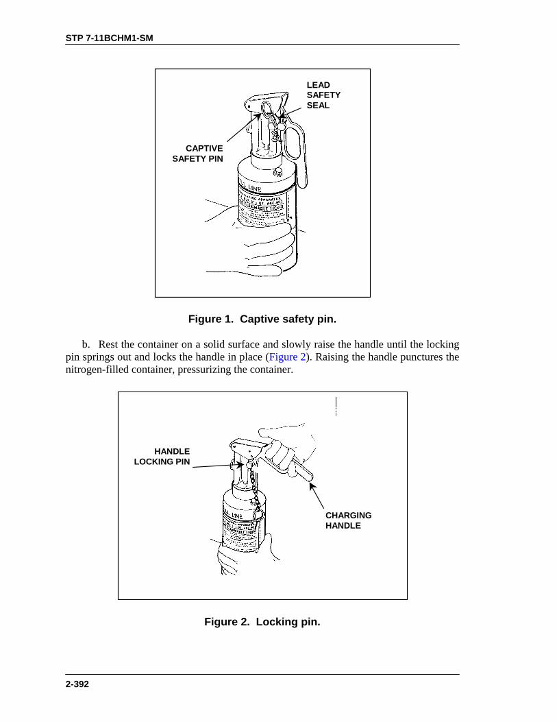
STP 7-11BCHM1-SM
2-392
LEADSAFETYSEAL
CAPTIVESAFETY PIN
Figure 1. Captive safety pin.
b. Rest the container on a solid surface and slowly raise the handle until the locking pin springs out and locks the handle in place (Figure 2). Raising the handle punctures the nitrogen-filled container, pressurizing the container.
HANDLELOCKING PIN
CHARGINGHANDLE
Figure 2. Locking pin.

STP 7-11BCHM1-SM
2-393
3. Decontaminate equipment.
WARNING1. Do not use DS2 to decontaminate personnel. It irritates
the skin and eyes. If DS2 gets on your skin, blot off theDS2 and rinse off your skin with water.
2. Wear a chemical/biological protective mask when usingthe apparatus to decontaminate.
a. Spray DS2 by depressing the thumb lever (Figure 3).
THUMB LEVER
Figure 3. Thumb lever.
b. Spray the most-touched and most-used parts of vehicles such as door handles, steering wheels, controls, seats, dashboards, levers, gasoline caps, and tools. Hold the apparatus upright to force as much liquid as possible from the container. Remember that you can discharge the contents of one full container in about 30 seconds of continuous spraying time. c. After you have expended the first nitrogen-filled cylinder, shake the container to determine whether you have completely emptied it. Use a second nitrogen-filled cylinder to expel remaining contents.
WARNINGPlace the handle in the lowered position before installingthe nitrogen-filled cylinder to prevent premature puncturingof the cylinder and its expulsion out of the spray head.

STP 7-11BCHM1-SM
2-394
d. To use the spare nitrogen-filled cylinder, depress the handle locking pin and lower the handle. Raise the thumb lever and push the expended cylinder out of the spray head body. Discard the expended cylinder. Insert the spare nitrogen-filled cylinder in the spray head body, neck down. Release the thumb lever and repressurize the apparatus repeating step 2b. e. When you have expended the charge, depress the handle locking pin and lower the handle. If you have completed the spraying, reinstall the captive safety pin and replace the apparatus in the mounting bracket. If not, repeat steps 1 through 3 until you have finished spraying down the vehicle or equipment. f. Whenever possible, rinse all items sprayed with DS2. However, do not rinse them until at least 30 minutes after you finish spraying them.
EVALUATION PREPARATION Setup: Do not use DS2 for training. Use 0.5 ounce of corrosion inhibitor (NSN 6850-00-865-2916) and water. Before setting up for evaluation, refer to paragraph 2-7 of TM 3-4230-204-12&P. For test purposes, the soldier must wear MOPP4. You will specify the area on a vehicle or piece of equipment that the soldier must decontaminate using the ABC M11. Brief Soldier: Tell the soldier to decontaminate equipment using ABC M11 decontaminating apparatus.
EVALUATION GUIDE
Performance Measures
Results
1. Fill M11 decontaminating apparatus. a. Unscrew spray head assembly from container body.
P F
b. Fill liquid to the yellow fill line (1 1/3 quarts). c. Check preformed packing in the spray head assembly. d. Screw spray head assembly firmly into the opening of thecontainer body.
2. Pressurize M11 decontaminating apparatus. a. Withdraw captive safety pin.
P F
b. Place M11 on a solid surface. c. Raise charging handle until locking pin springs out. d. Puncture nitrogen-filled cylinder to pressurize M11 container.
3. Decontaminate equipment. a. Spray mission-essential parts of equipment.
P F
b. Use second nitrogen cylinder to expel the remaining contents,if any.
c. Depress the handle locking pin and lower the handle. d. Replace used nitrogen-filled cylinder.
STP 7-11BCHM1-SM
2-395
EVALUATION GUIDE
Performance Measures
Results
e. Reinstall captive safety pin. f. Replace apparatus in the mounting bracket.
FEEDBACK
If the soldier passes all steps, score him GO. If he fails any steps, score him NO-GO, then show him what he did wrong and how to do it correctly.
REFERENCES
Required Related None TM 3-4230-204-12&P

STP 7-11BCHM1-SM
2-396
NIGHT VISION DEVICES
MAINTAIN NIGHT VISION GOGGLES AN/PVS-7B 071-710-0009
CONDITIONS Given night vision goggles AN/PVS-7B with components, accessories, batteries, clean water, and clean, lint-free cloths, and a requirement to perform required operator maintenance on the goggles. STANDARDS Clean and inspect night vision goggles, components, and accessories for serviceability; report unserviceable items to the supervisor. Properly stow the goggles and accessories. Comply with all warnings and cautions associated with these goggles.
TRAINING AND EVALUATION Training Information Outline
1. Inventory the carrying case for the following items (Figure 1). a. Headmount assembly. b. Demist shields. c. Brow pads--medium and thick (the thin pad is attached to the headmount assembly). d. Operator’s manual. e. Lens paper. f. Carrying case strap. g. Light interference filter (LIF). h. Sacrificial window. i. Batteries: (2 BA-3058/U or 1 BA-5567/U). j. Goggles assembly. 2. Clean the AN/PVS-7B. a. Clean all optical surfaces with lens paper dampened with clean water (water temperature should be between 70° and 80° Fahrenheit), and wipe clean. b. Use a clean, lint-free cloth, dampened with clean water, to remove all dirt and grease from all exterior surfaces.

STP 7-11BCHM1-SM
2-397
HEADMOUNTASSEMBLY
CARRYING CASE
ACCESSORYPOCKET
DEMISTSHIELDS
BA-3058/UBA-5567/U
LIF
CARRYINGCASE STRAP
MEDIUMAND THICK
BROW PADS
OPERATOR’SMANUAL
LENSPAPER
GOGGLESASSEMBLY SACRIFICIAL
WINDOW
Figure 1. AN/PVS-7B night vision goggles with case and accessories.
CAUTIONHandle all optical components with extreme care. Protectagainst dirt, dust, fingerprints, and excessive moisture.
3. Inspect the accessories and goggles for conditions indicated. Take corrective action as indicated for damaged items (Figure 2). a. Goggles assembly. (1) Inspect all lenses for dirt, fingerprints, residue, chips, or cracks. If necessary, use clean water and lens tissues to wash and dry the lens. If you observe chips or cracks in a lens, refer to your supervisor for a higher level of maintenance. (2) Inspect the goggles housing for damage. If you observe chips or cracks, refer to your supervisor for a higher level of maintenance. (3) Inspect the battery compartment for corrosion, defective battery cap spring contact, and preformed packing in the cap. If you find corrosion, or if the battery cap spring is defective, refer to your supervisor for a higher level of maintenance.

STP 7-11BCHM1-SM
2-398
(4) Check the diopter adjustment rings to make sure the eyepieces move freely. If they do not, refer to your supervisor for a higher level of maintenance. (5) Check the inter-pupillary adjustment on the eyepiece to see if it moves freely. If it does not, refer to your supervisor for a higher level of maintenance. (6) Turn the objective lens focus knob to make sure it moves freely. The knob should turn about 1/3 turn, or 120 degrees. If the knob does not move freely, refer to your supervisor for a higher level of maintenance. (7) Inspect for bent, broken, dried, cracked, torn, dusty, dirty, or improperly fitting eye cups. If necessary, clean and dry the eye cups with clean water and a lens tissue. If the eye cups are defective, refer to your supervisor for a higher level of maintenance. (8) Check the OFF-ON-PULL/IR switch. Move the switch from OFF, to ON, and to PULL/IR. Each position should have a definite stopping point. If the knob is broken or missing, or if the switch has no definite stops, refer to your supervisor for a higher level of maintenance. (9) Inspect the headmount assembly (Figure 3). (a) Inspect the headmount strap assemblies and brow pads for holes, crack, defective fasteners, or contamination. Remove and replace the brow pad by pulling it out (hook-pile tape holds the brow pad in place). Press in a new pad.
INTERPUPILLARYADJUSTMENT
DIOPTERADJUSTMENT
EYEPIECE ANDEYECUPS
BATTERYCAP
LENSCAP
OBJECTIVELENS FOCUS
SACRIFICIALWINDOW
LIGHTINTERFERENCE
FILTER (LIF)
HIGH LIGHTDETECTOR
INFRAREDSOURCE
OFF-ON-IRSWITCH
NECKCORD
DIPOTERRETAININGRING
DEMISTSHIELDS
Figure 2. Functional features and accessories.
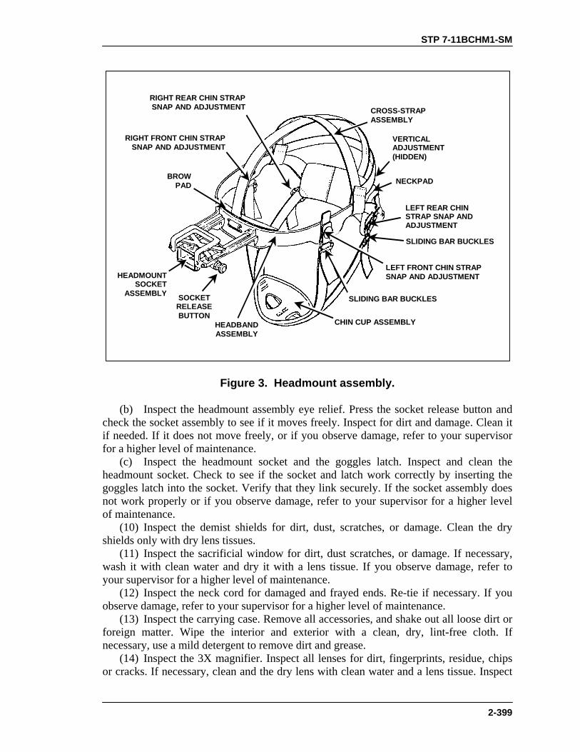
STP 7-11BCHM1-SM
2-399
BROWPAD
HEADMOUNTSOCKET
ASSEMBLY SOCKETRELEASEBUTTON
CHIN CUP ASSEMBLY
SLIDING BAR BUCKLES
LEFT REAR CHINSTRAP SNAP ANDADJUSTMENT
NECKPAD
VERTICALADJUSTMENT(HIDDEN)
CROSS-STRAPASSEMBLY
LEFT FRONT CHIN STRAPSNAP AND ADJUSTMENT
RIGHT REAR CHIN STRAPSNAP AND ADJUSTMENT
RIGHT FRONT CHIN STRAPSNAP AND ADJUSTMENT
SLIDING BAR BUCKLES
HEADBANDASSEMBLY
Figure 3. Headmount assembly.
(b) Inspect the headmount assembly eye relief. Press the socket release button and check the socket assembly to see if it moves freely. Inspect for dirt and damage. Clean it if needed. If it does not move freely, or if you observe damage, refer to your supervisor for a higher level of maintenance. (c) Inspect the headmount socket and the goggles latch. Inspect and clean the headmount socket. Check to see if the socket and latch work correctly by inserting the goggles latch into the socket. Verify that they link securely. If the socket assembly does not work properly or if you observe damage, refer to your supervisor for a higher level of maintenance. (10) Inspect the demist shields for dirt, dust, scratches, or damage. Clean the dry shields only with dry lens tissues. (11) Inspect the sacrificial window for dirt, dust scratches, or damage. If necessary, wash it with clean water and dry it with a lens tissue. If you observe damage, refer to your supervisor for a higher level of maintenance. (12) Inspect the neck cord for damaged and frayed ends. Re-tie if necessary. If you observe damage, refer to your supervisor for a higher level of maintenance. (13) Inspect the carrying case. Remove all accessories, and shake out all loose dirt or foreign matter. Wipe the interior and exterior with a clean, dry, lint-free cloth. If necessary, use a mild detergent to remove dirt and grease. (14) Inspect the 3X magnifier. Inspect all lenses for dirt, fingerprints, residue, chips or cracks. If necessary, clean and the dry lens with clean water and a lens tissue. Inspect

STP 7-11BCHM1-SM
2-400
the housing for damage. If you observe any chips or cracks in the housing, refer to your supervisor for a higher level of maintenance. (15) Inspect the snap-on compass for dirt and damage. If necessary, clean it with clean water and a cloth. If you observe damage, refer to your supervisor for a higher level of maintenance. 4. Perform an operational check. a. Install batteries (Figure 4).
LITHIUM(BA-5567/U)
OFF-ON-IRSWITCH
BATTERYCAP
AA (BA-3058/U)
Figure 4. Battery installation.
(1) Check and make certain that the OFF-ON-PULL/IR switch is in the OFF position. (2) Comply with all cautions, warning, and danger statements. (3) Remove the battery cap. Insert two AA batteries (BA-3058/U) or one lithium battery (BA-5567/U) in the battery compartment, with the positive end (+) first. (4) Replace the battery cap. Tighten it firmly to ensure a watertight seal (Figure 4).

STP 7-11BCHM1-SM
2-401
WARNING• Alkaline, lithium, and mercury batteries are potential
hazards. Do not heat, puncture, disassemble,short-circuit, try to recharge, or otherwise tamper withthe batteries.
• If the battery compartment becomes unusually hot, turnoff the equipment. Try to wait until the batteries coolbefore you remove them.
• Batteries have safety vents to prevent explosion. Whenthey vent, you will notice an irritating odor or hear thesound of gas escaping. After batteries vent, they arefairly safe, but you must still handle them with care.
DANGERIF YOU INHALE SULPHUR DIOXIDE, SEEK MEDICALATTENTION.
b. Check goggles for proper operation. Perform the following procedures only in darkened conditions. If you must check the goggles during daylight, use the lens cap to cover the objective lens: (1) Position the OFF-ON-PULL/IR switch to ON. Note the green glow that gradually appears in each eyepiece. (2) Pull the OFF-ON-PULL/IR knob. Rotate it clockwise to the IR position. Note the red light that appears in the left eyepiece. This light indicates that the IR source is operating. The IR source is located on the left front of the goggles. Do not block the IR source when operating the goggles. (3) Turn the OFF-ON-PULL/IR switch counterclockwise to the OFF position. Note that the red light and green glow disappear. (4) Shut down the goggles by positioning the OFF-ON-PULL/IR switch to OFF. 5. Stow the night vision goggles (Figure 5). a. Unscrew the battery cap, remove battery, and replace the battery cap. b. Place demist shields and battery into their proper carrying case Pocket.

STP 7-11BCHM1-SM
2-402
HEAD-MOUNT ASSEMBLYCARRYING CASE
DEEP POCKET
ACCESSORY POCKETGOGGLE ASSEMBLY SHALLOW POCKET
Figure 5. Goggles stowed in the carrying case.
CAUTIONPlace the sacrificial window at the bottom left or right corner ofthe carrying case accessory pocket to prevent damage towindow.
c. Place the lens paper, sacrificial window, and operator’s manual in the accessory pocket located under the shallow pocket that contains the goggles. d. Place the goggles (objective lens down) into shallow pocket of carrying case. e. Stow the headmount assembly in the deep pocket of the carrying case. Close the carrying case.
EVALUATION PREPARATION Setup: Provide the soldier with equipment and materials listed in conditions. Brief soldier: Tell him that he is to inspect the components, accessories, and goggles for completeness and serviceability, and to clean them as required. Then he is to perform an operational check, shut down the goggles, and stow them and their accessories.
EVALUATION GUIDE Performance Measures
Results
1. Inventory carrying case for correct content.
P F
2. Clean the AN/PVS-7B and accessories using correct cleaningtechniques.
P F
STP 7-11BCHM1-SM
2-403
EVALUATION GUIDE Performance Measures
Results
3. Inspect accessories and goggles for serviceability.
P F
4. Perform an operational check.
P F
5. Stow the night vision goggles.
P F
6. Comply with safety precautions and warnings. P F
FEEDBACK If the soldier passes all steps, score him GO. If he fails any steps, score him NO-GO, then show him what he did wrong and how to do it correctly.
REFERENCES
Required Related TM 11-5855-262-10-2 None

STP 7-11BCHM1-SM
2-404
OPERATE NIGHT VISION GOGGLES AN/PVS-7B 071-710-0008
CONDITIONS At night, given night vision goggles AN/PVS-7B with components, accessories, and batteries. STANDARDS Inspect night vision goggles AN/PVS-7B for best operational capability. Correctly shut down goggles. Properly stow goggles and all accessories in carrying case. Comply with all warnings and cautions associated with the goggles.
TRAINING AND EVALUATION Training Information Outline
WARNINGTo avoid personal injury or damage to the AN/PVS-7Bgoggles, consider the following limitations and safetyprecautions while using the goggles:1. The goggles require some moonlight, starlight, or both
to operate.2. The amount of available light determines the goggles’
level of performance.3. Operating in shadow from buildings or trees reduces
nightlight.4. The goggles are less effective for viewing into
shadowed and other darkened areas than inlighter areas.
5. The goggles are less effective when viewing throughrain, fog, sleet, snow, or smoke.
6. When using goggles from a moving vehicle in the fog,rain, sleet, snow, or smoke, vehicle speed must bereduced to avoid over-driving the range of view.
7. Between the last and first quarters of the moon, duringoperations requiring the use of a protective mask, orboth, the assistant driver should use a night-vision device.
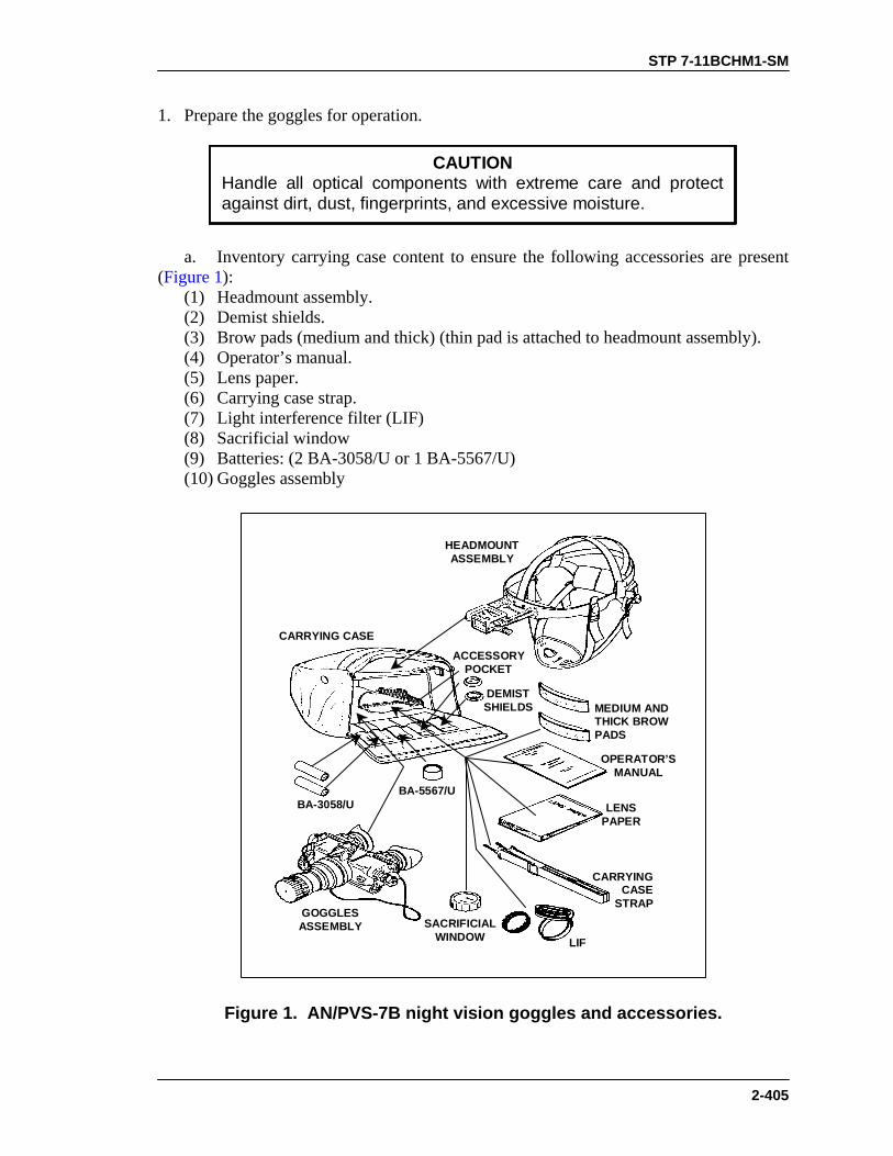
STP 7-11BCHM1-SM
2-405
1. Prepare the goggles for operation.
CAUTIONHandle all optical components with extreme care and protectagainst dirt, dust, fingerprints, and excessive moisture.
a. Inventory carrying case content to ensure the following accessories are present (Figure 1): (1) Headmount assembly. (2) Demist shields. (3) Brow pads (medium and thick) (thin pad is attached to headmount assembly). (4) Operator’s manual. (5) Lens paper. (6) Carrying case strap. (7) Light interference filter (LIF) (8) Sacrificial window (9) Batteries: (2 BA-3058/U or 1 BA-5567/U) (10) Goggles assembly
HEADMOUNTASSEMBLY
CARRYING CASE
ACCESSORYPOCKET
DEMISTSHIELDS
BA-3058/UBA-5567/U
LIF
CARRYINGCASE
STRAP
MEDIUM ANDTHICK BROWPADS
OPERATOR’SMANUAL
LENSPAPER
GOGGLESASSEMBLY SACRIFICIAL
WINDOW
Figure 1. AN/PVS-7B night vision goggles and accessories.

STP 7-11BCHM1-SM
2-406
b. Inspect the goggles assembly and components for serviceability. (1) Ensure that the goggles assembly rotary switch is in the OFF position. Inspect goggles assembly and components for any damage to optical surfaces, body, eyecups, OFF-ON-PULL/IR switch, and battery cap. (2) Ensure all optical surfaces are clean. Clean with clean water and lens tissue if needed (Figure 2).
INTERPUPILLARYADJUSTMENT
DIOPTERADJUSTMENT
EYEPIECE ANDEYECUPS
BATTERYCAP
LENSCAP
OBJECTIVELENS FOCUS
SACRIFICIALWINDOW
LIGHTINTERFERENCE
FILTER (LIF)
HIGH LIGHTDETECTOR
OFF-ON-IRSWITCH
NECKCORD
DIOPTERRETAINING
RING
DEMISTSHIELDS
IRSOURCE
Figure 2. Optical surfaces and other components.
c. Install batteries. (1) Check and ensure that the OFF-ON-PULL/IR switch is in the OFF position before installing batteries. (2) Comply with all warnings and danger statements that apply to handling batteries.

STP 7-11BCHM1-SM
2-407
WARNING• Batteries (alkaline, lithium, and mercury) present a
potential hazard. Do not heat, puncture, disassemble,short-circuit, try to recharge, or otherwise tamper withthe batteries.
• If the battery compartment becomes unusually hot, turnoff the equipment. Try to wait until the batteries coolbefore you remove them.
• Batteries have safety vents to prevent explosion. Whenthey vent, you will notice an irritating odor or hear thesound of gas escaping. After batteries vent, they arefairly safe, but you must still handle them with care.
DANGERIF YOU INHALE SULPHUR DIOXIDE, SEEK MEDICALATTENTION.
(3) Remove the battery cap. Insert two AA batteries (BA-3058/U) or one lithium battery (BA-5567/U) in the battery compartment, positive end (+) first. (4) Replace the battery cap. Tighten it firmly to ensure a watertight seal (Figure 3).
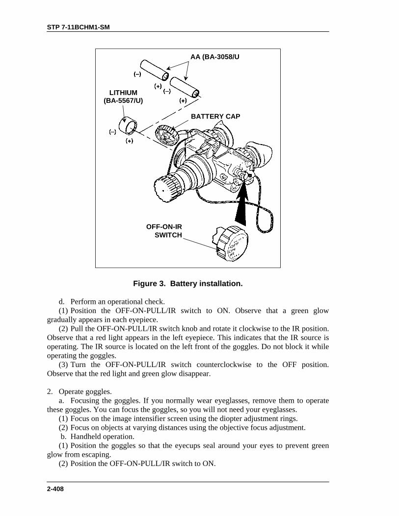
STP 7-11BCHM1-SM
2-408
LITHIUM(BA-5567/U)
OFF-ON-IRSWITCH
BATTERY CAP
AA (BA-3058/U
Figure 3. Battery installation.
d. Perform an operational check. (1) Position the OFF-ON-PULL/IR switch to ON. Observe that a green glow gradually appears in each eyepiece. (2) Pull the OFF-ON-PULL/IR switch knob and rotate it clockwise to the IR position. Observe that a red light appears in the left eyepiece. This indicates that the IR source is operating. The IR source is located on the left front of the goggles. Do not block it while operating the goggles. (3) Turn the OFF-ON-PULL/IR switch counterclockwise to the OFF position. Observe that the red light and green glow disappear. 2. Operate goggles. a. Focusing the goggles. If you normally wear eyeglasses, remove them to operate these goggles. You can focus the goggles, so you will not need your eyeglasses. (1) Focus on the image intensifier screen using the diopter adjustment rings. (2) Focus on objects at varying distances using the objective focus adjustment. b. Handheld operation. (1) Position the goggles so that the eyecups seal around your eyes to prevent green glow from escaping. (2) Position the OFF-ON-PULL/IR switch to ON.

STP 7-11BCHM1-SM
2-409
(3) Adjust the interpupillary distance by sliding the eyepieces either together or apart so both eyes can observe the entire field of view at the same time. (4) To set the diopter adjustment rings, close your left eye and adjust the right diopter ring for the clearest focus on the image intensifier screen. Then, close your right eye and adjust the left diopter ring for the clearest focus on the image intensifier screen. (5) Adjust objective lens focus while observing a distant object (at least 4 meters distance) until the sharpest view is obtained. c. Head mount operation. (1) Adjust the headmount assembly (Figure 4).
BROW PAD
HEADMOUNTSOCKET
ASSEMBLY
SOCKETRELEASEBUTTON HEADBAND
ASSEMBLYCHIN CUP ASSEMBLY
SLIDING BAR BUCKLES
LEFT REAR CHIN STRAPSNAP AND ADJUSTMENT
NECKPAD
VERTICALADJUSTMENT(HIDDEN)
CROSS-STRAPASSEMBLY
LEFT FRONT CHIN STRAPSNAP AND ADJUSTMENT
RIGHT REAR CHIN STRAPSNAP AND ADJUSTMENT
RIGHT FRONT CHIN STRAPSNAP AND ADJUSTMENT
SLIDING BAR BUCKLES
Figure 4. Headmount assembly.
(a) Loosen the four chin straps on the headmount assembly until the end of each strap is about 2 inches from the sliding bar buckles. NOTE: When installing a headmount assembly over a protective mask, make sure you
do not break the seal of the protective mask around your face. (b) Grasp the neck pad assembly with both hands. Pull it over your head and down to the back of your neck. If the head mount is too loose, replace the thin pad with the medium or thick brow pad. The pads are held in place by hook-pile tape. (c) Fasten the front and rear snaps in place with your left hand. Hold the chin cup in position on your chin. Adjust both rear chin assembly straps until you feel light pressure against your chin. Stop. Do not tighten the strap any farther. (d) Continue to hold the chin cup in position. At the same time, remove slack from the front and rear chin straps. Once you have done so--stop. Do not tighten them any farther.
STP 7-11BCHM1-SM
2-410
(e) Make sure you the cross-strap assembly does not twist. To remove slack from it, adjust the vertical adjustment strap at the neck pad. (f) Adjust the chin straps and the vertical adjustment strap until both the chin cup and the headband assembly are in a comfortable but firm position. (g) Depress the socket release button. Position the headmount socket all the way forward. (2) Install the goggles on the headmount assembly. (a) Align the goggles latch with the headmount socket. Press and hold the goggles latch lever while you place the goggles into the headmount socket. Release the latch when the goggles fully engage the socket. (b) Depress the socket release button. Move the goggles back toward your eyes until the eyecups and eyepieces are comfortably aligned. The eyecups must seal around your eyes and prevent the green glow from escaping. (3) Adjust goggles for operation. (a) Position the OFF-ON-PULL/IR switch to ON. (b) Adjust the interpupillary distance. Slide the eyepieces either together or apart so you can observe the entire FOV with both eyes at the same time. (c) Set the diopter adjustment rings. Close your left eye and adjusting the right diopter ring for the clearest focus on the image intensifier screen. Close your right eye and adjust the left diopter ring for the clearest focus on the image intensifier screen. (d) Adjust the eye relief distance. Press the socket release button. Move the goggles backward or forward to obtain a full field of view of the image intensifier. If necessary, readjust the diopter rings to obtain the best image. (e) Adjust the objective lens focus while observing a distant object (at least 4 meters away) until you obtain the sharpest possible view. (f) Readjust the vertical strap assembly until the goggles align with your eyes. (g) If necessary, adjust the kevlar or M1 headband inside the helmet for a proper fit over the headmount assembly. 3. Operate goggles under unusual conditions. a. Extreme darkness. (1) Pull the OFF-ON-PULL/IR switch out and rotate it clockwise to the IR position. (2) Ensure the eyecups are positioned to prevent light escaping from the goggles.
WARNINGThe infrared source is a light that is invisible to the unaidedeye for use during conditions of extreme darkness.However, the enemy can detect it with night vision devices.The infrared source is used to see objects within a distanceof 3 meters.
b. Dust and sand. Attach the sacrificial window to protect the objective lens from scratches and other damage. (1) Remove the sacrificial window from the carrying case. (2) Carefully push the sacrificial window over the objective lens until it stops.

STP 7-11BCHM1-SM
2-411
(3) Turn the sacrificial window clockwise until it snaps in place. (4) Remove the sacrificial window by reversing the installation procedures. c. Rainy and humid conditions. Install demist shields to minimize diopter fog. (1) Remove the eyecups by carefully pulling them off the diopter ring. (2) Carefully press a demist shield onto each eyepiece. Do not smudge eyepieces or demist shields. (3) Replace eyecups. Press each eyecup over the diopter retainer ring. Rotate it into correct viewing position. d. Laser threat environment. Install the light interference filter (LIF). Using this filter will slightly reduce system gain. (1) Remove the container/wrench from the carrying case. (2) Remove the lens cap or sacrificial window from the objective lens of the goggles. (3) Open the container/wrench and remove the LIF. (4) Hold the LIF by the notched end. Thread it clockwise into the end of the objective lens. (5) Use the ridged side of the container/wrench as a wrench. Engage the ridges on the container with the ridges on the LIF. Hand tighten the LIF. (6) Place the empty container/wrench back into the pouch in the carrying case. NOTE: The lens cap and the sacrificial window will fit onto the end of the objective
lens with the LIF in place. However, the lens cap and sacrificial window will not snap into place without the LIF attached.
(7) Replace the lens cap or the sacrificial window onto the end of the objective lens and over the LIF. (8) Remove the LIF by reversing the installation procedures. e. NBC environment. (1) Place the protective mask on your head per instructions provided with the protective mask. (2) Make sure you do not break the seal of the protective mask around your face when you install the headmount assembly over the protective mask. 4. Install and operate the snap-on compass. a. Remove the objective lens cover from the goggles. Secure the snap-on compass to the lens with the round part of the activation button facing down. b. Turn the goggles on. Push up on the activation button to determine azimuth direction. 5. Attach the 3X magnifier telescope assembly. a. Objective focus cover attached. Push the objective focus cover sleeve onto the goggles’ objective focus ring. b. Objective focus cover not attached to goggles. Screw the 3X magnifier directly into the goggles’ objective focus ring. 6. Stow the night vision goggles (Figure 5).
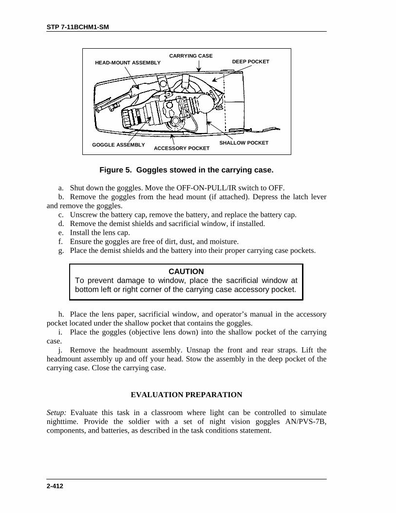
STP 7-11BCHM1-SM
2-412
HEAD-MOUNT ASSEMBLYCARRYING CASE
DEEP POCKET
SHALLOW POCKETACCESSORY POCKETGOGGLE ASSEMBLY
Figure 5. Goggles stowed in the carrying case.
a. Shut down the goggles. Move the OFF-ON-PULL/IR switch to OFF. b. Remove the goggles from the head mount (if attached). Depress the latch lever and remove the goggles. c. Unscrew the battery cap, remove the battery, and replace the battery cap. d. Remove the demist shields and sacrificial window, if installed. e. Install the lens cap. f. Ensure the goggles are free of dirt, dust, and moisture. g. Place the demist shields and the battery into their proper carrying case pockets.
CAUTIONTo prevent damage to window, place the sacrificial window atbottom left or right corner of the carrying case accessory pocket.
h. Place the lens paper, sacrificial window, and operator’s manual in the accessory pocket located under the shallow pocket that contains the goggles. i. Place the goggles (objective lens down) into the shallow pocket of the carrying case. j. Remove the headmount assembly. Unsnap the front and rear straps. Lift the headmount assembly up and off your head. Stow the assembly in the deep pocket of the carrying case. Close the carrying case.
EVALUATION PREPARATION Setup: Evaluate this task in a classroom where light can be controlled to simulate nighttime. Provide the soldier with a set of night vision goggles AN/PVS-7B, components, and batteries, as described in the task conditions statement.

STP 7-11BCHM1-SM
2-413
1. Have the soldier prepare the goggles for operation, operate the goggles using the headmount assembly, shut down the goggles, and stow the goggles.
2. Evaluate the soldier’s ability to select and attach the appropriate components by
telling him to prepare the goggles for operation in the following conditions: dust and sand, rain or high humidity, or laser threat environment. If a snap-on compass and 3X magnifier are available, evaluate the soldier’s ability to attach them to the goggles.
Brief soldier: Tell the soldier that he is to prepare the goggles for operation, operate the goggles using the headmount assembly, shut down and stow the goggles, and attach components to operate the goggles in various conditions as instructed. Tell him that he must notify you before turning the goggles ON and after turning them OFF, so you can darken or lighten the room. Tell the soldier not to energize the goggles when the room lights are on.
EVALUATION GUIDE Performance Measures
Results
1. Prepare goggles for operation. a. Inventory carrying case content to ensure all accessories are present.
P F
b. Inspect the goggles assembly and components for serviceability. c. Install batteries correctly. d. Perform an operational check.
2. Operate goggles in hand-held mode.
P F
3. Operate goggles with head mount. a. Adjust the headmount assembly for proper fit.
P F
b. Install goggles correctly on the headmount assembly. c. Adjust goggles for operation.
4. Operate goggles during unusual conditions. a. Extreme darkness. Operate goggles using IR source.
P F
b. Dust and sand. Attach the sacrificial window. c. Rainy and humid conditions. Install demist shields to minimize diopter fog.
d. Laser threat environment. Install the light interference filter (LIF).
e. NBC environment. (1) Place the protective mask on your head IAW instructions provided with the protective mask.

STP 7-11BCHM1-SM
2-414
EVALUATION GUIDE Performance Measures
Results
(2) Do not break the seal of the protective mask around your face when you install the headmount assembly over the protective mask.
5. Install and operate snap-on compass (if available).
P F
6. Attach 3X magnifier telescope assembly (if available).
P F
7. Stow the night vision goggles. P F
FEEDBACK
If the soldier passes all steps, score him GO. If he fails any steps, score him NO-GO, then show him what he did wrong and how to do it correctly.
REFERENCES Required Related TM 11-5855-262-10-2 None

STP 7-11BCHM1-SM
2-415
OPERATE NIGHT VISION SIGHT AN/PVS-4 071-315-0003
CONDITIONS At night, given an AN/PVS-4 sight in its carrying case and BA-1567/U batteries. STANDARDS Prepare and correctly place the AN/PVS-4 sight into operation, then shut it down and store it.
TRAINING AND EVALUATION
Training Information Outline
1. Unpack the sight.
CAUTIONTo relieve air pressure inside the carrying case, press the coreof the relief valve, located near the handle, before releasing thelatches.
a. Release the four latches securing the top of the carrying case and remove the top. b. Remove the carrying bag from the carrying case. Open the bag and remove the sight. c. Inspect the sight for damage (cracks, chips, abrasions) and ensure that the decals are readable. Report deficiencies.
CAUTIONAN/PVS-4 sights are precision electro-optical instruments. Theymust always be handled carefully. Be sure to turn the ON-OFF/TUBE BRIGHTNESS and ON-OFF/RETICLEBRIGHTNESS switches OFF before installing batteries.
2. Install the batteries (Figure 1).

STP 7-11BCHM1-SM
2-416
OBJECTIVE LENSASSEMBLY
EYEPIECEASSEMBLY
BATTERY
CAP
IMAGEINTENSIFIER
ASSEMBLY(INSIDE)
BATTERYHOUSING
ASSEMBLY
BATTERY
CAP
Figure 1. Battery emplacement.
a. Remove the battery caps by turning them counterclockwise. b. Insert a battery in each cap with the negative (-) terminal (raised end) facing into the cap. c. Replace the battery caps and tighten them snugly. 3. Operate the device under normal conditions (Figure 2).
OBJECTIVEFOCUS RING
DIOPTERFOCUS RING
DIOPTERINDICATOR
ON-OFF TUBEBRIGHTNESS
RETICLE ELEVATIONADJUSTMENT
ACTIVATOR
RETICLE AZIMUTHADJUSTMENT
ACTIVATOR
ON-OFF RETICLEBRIGHTNESS
Figure 2. Controls and indicators.

STP 7-11BCHM1-SM
2-417
WARNINGUsing the sight without the eye guard installed may causedetection by the enemy and, when operated on a weapon,can result in physical injury to the operator because ofweapon recoil.
NOTES: 1. The daylight cover must be installed during the daylight and removed at
night. 2. Batteries must be removed when the sight is not in use, to prevent
accidentally turning on the sight. a. Press the eye against the eye guard to open the rubber leaves that prevent the emission of stray light. b. Turn the ON-OFF/TUBE BRIGHTNESS control clockwise to turn on the sight. NOTE: If the equipment fails to operate, refer to the troubleshooting procedures in
TM 11-5855-213-10. c. Adjust the ON-OFF/TUBE BRIGHTNESS control to the lowest setting that provides good target-to-background contrast. d. Turn the ON-OFF/RETICLE BRIGHTNESS control clockwise to turn on the light-emitting diode. Adjust the light intensity so that the reticle is just visible against the background.
CAUTIONExcessive reticle brightness may damage the image-intensifier tube.
e. Turn the diopter focus ring (Figure 2) to obtain the clearest image of the reticle pattern. f. Turn the objective focus ring (Figure 2) until the target in the field of view is sharply defined. NOTE: During surveillance or target engagement, the operator must adjust the
objective focus to ensure a sharp image at different ranges. 4. Perform after-operation procedures. a. Turn the reticle and tube brightness controls fully counterclockwise. b. Remove both batteries. c. Replace the sight in the carrying case.
STP 7-11BCHM1-SM
2-418
EVALUATION PREPARATION
Setup: At the test site, provide all the materials and equipment given in the task conditions statement. Brief Soldier: Tell the soldier to remove the AN/PVS-4 sight from its carrying case and place them into operation. Tell him to take the AN/PVS-4 sight out of operation and replace it in its carrying case.
EVALUATION GUIDE
Performance Measures
Results
NOTE: Steps 1 and 2 are to be executed in sequence.
1. Remove sight from the carrying case. a. Release the air pressure.
P F
b. Release the latches. c. Inspect the sight for damages.
2. Install the batteries. a. Place the ON-OFF/TUBE BRIGHTNESS switch to OFF.
P F
b. Place the ON-OFF/RETICLE BRIGHTNESS switch to OFF. c. Remove the battery caps (two each). d. Insert the batteries (two each) correctly (negative [-] terminal facing into the cap). e. Replace caps (two each).
3. Turn the ON-OFF/tube brightness control to ON.
P F
4. Turn the ON-OFF/reticle brightness control to ON.
P F
5. Perform after-operation procedures. a. Turn the ON-OFF/tube brightness control to OFF.
P F
b. Turn the ON-OFF/reticle brightness control to OFF. c. Remove both batteries. d. Replace the sight in the carrying case.
FEEDBACK
If the soldier passes all steps, score him GO. If he fails any steps, score him NO-GO, then show him what he did wrong and how to do it correctly.

STP 7-11BCHM1-SM
2-419
REFERENCES
Required Related None TM 11-5855-213-10

STP 7-11BCHM1-SM
2-420
OPERATE NIGHT VISION GOGGLES AN/PVS-5 071-315-0030
CONDITIONS At night, given serviceable AN/PVS-5 night vision goggles with components, accessories, and batteries. STANDARDS While using the AN/PVS-5 night vision goggles during performance of assigned mission, comply with all appropriate warnings and cautions. Inspect and operate the goggles to obtain the best possible image. Properly shut down the goggles. Stow them with their accessories in the carrying case.
TRAINING AND EVALUATION Training Information Outline
WARNINGTo avoid injuring yourself or damaging the goggles,remember the following equipment limitations and safetyprecautions while using them:• You must have some light (moonlight or starlight) to
operate the goggles.• You will have less light when operating under trees, in
building shadows, under passing cloud cover,and so on.
• If you try to view into shadows and other darkenedareas, the equipment will be less effective.
• The equipment does not operate through rain, fog,sleet, snow, or smoke.
• When conditions exist that may or do reduce yourvision, adjust the speed of the vehicle to avoidoverdriving your range of view.
• If the moon is between its last and first quarters, if theoperation requires use of protective masks, or both,equip the assistant driver with a night vision device.
1. Check the carrying case for correct contents.

STP 7-11BCHM1-SM
2-421
CAUTIONHandle all optical components with extreme care, and protectthem against dirt, dust, fingerprints, and excessive moisture.
a. Remove the goggles assembly from the carrying case. Place the neck cord around your neck. b. Inventory the carrying case to make sure the items it contains are correct for the model you are using (Figure 1).
BATTERYBA-5567/U
DEMISTSHIELD
CARRYING CASEAN/PVS-5, AN/PVS-5A
INSTRUCTIONSHEET
SOCKETHEADKEY
BATTERYBA-3058/U
BATTERYBA-5567/U
DEMISTSHIELDS
CARRYING CASEAN/PVS-5B, AN/PVS-5C
SOCKETHEADKEY
LENSPAPER
Figure 1. Carrying case items.
2. Install the batteries. Figure 2, Figure 3, and Figure 4 show the locations of the battery compartment and controls for the model you are using, as well as the type of battery you will need.

STP 7-11BCHM1-SM
2-422
WARNINGSBA-5567/U LITHIUM BATTERY
BA-5567/U lithium batteries contain sulfur dioxide gasunder pressure.DO NOT heat, puncture, disassemble, short-circuit, try torecharge, or otherwise tamper with the batteries.Turn off the goggles if the battery compartment getsabnormally hot. If you can, wait until the batteries havecooled before you remove them from the goggles.Batteries have safety vents to prevent explosion. Whilethey are venting, you will notice the irritating smell ofsulfur dioxide, hear gas escaping, or both. After thesafety vents have purged excess gas, the batteries arefairly safe from bursting, but you must still handle themwith care.If you inhale sulfur dioxide, seek medical attention.
BA-3058/U ALKALINE BATTERY• Do not heat or dispose of alkaline battery BA-3058/U
in fire.• Do not short-circuit or otherwise tamper with the
battery.• Return batteries to the property disposal officer.
a. Check and make certain that the rotary switch is in the OFF position before installing batteries. b. AN/PVS-5 and AN/PVS-5A (Figure 2). Remove the battery cap and insert one lithium battery (BA-5567/U) in the battery compartment with the positive (+) end first. Replace the battery cap and tighten it firmly to ensure a watertight seal.

STP 7-11BCHM1-SM
2-423
BATTERY CAP
BA-5567/U
(+)
(-)
ROTARYSWITCH
DIOPTERRING
INFRAREDILLUMINATOR
BINOCULARASSEMBLY(MONOCULAR
FOCUS KNOB
LEVER CLAMP
CLAMP KNOB
OBJECTIVE LENS
Figure 2. AN/PVS-5 and AN/PVS-5A goggles.
c. AN/PVS-5B (Figure 3). The AN/PVS-5B uses either one lithium battery or two alkaline batteries. Use only one type battery at a time. Remove the battery cap and insert two alkaline batteries (BA-3058/U) in the battery compartment with the negative (-) end first, or insert one lithium battery (BA-5567/U) in the battery compartment with the positive end (+) first. Replace the battery cap and tighten it firmly to ensure a watertight seal.

STP 7-11BCHM1-SM
2-424
(+)
(-)
BATTERY CAP
BA-5567/U
DIOPTER ADJUST RING
FOCUSKNOBS
BA-3058/U(AN/PVS 5B ONLY) CLAMP LEVER
CLAMP KNOBS
BA-3058/UBATTERYCAP
ROTARY SWITCH
LENS CAP
Figure 3. AN/PVS-5B goggles.
d. AN/PVS-5C (Figure 4). The AN/PVS-5C uses either one lithium battery or two alkaline batteries (in separate compartments). Use only one type battery at a time. Remove the battery caps and insert one alkaline battery (BA-3058/U) in each battery compartment with the negative (-) end first, or insert one lithium battery (BA-5567/U) in the battery compartment with the positive (+) end first. Replace the battery cap(s) and tighten it firmly to ensure a watertight seal.
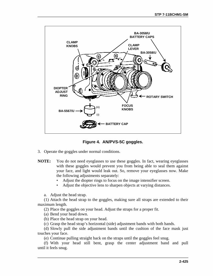
STP 7-11BCHM1-SM
2-425
(+)
(-)
BA-3058/UBATTERY CAPS
BATTERY CAP
BA-5567/U
DIOPTERADJUST
RING
FOCUSKNOBS
CLAMPLEVER
CLAMPKNOBS
ROTARY SWITCH
BA-3058/U
Figure 4. AN/PVS-5C goggles.
3. Operate the goggles under normal conditions. NOTE: You do not need eyeglasses to use these goggles. In fact, wearing eyeglasses
with these goggles would prevent you from being able to seal them against your face, and light would leak out. So, remove your eyeglasses now. Make the following adjustments separately:
• Adjust the diopter rings to focus on the image intensifier screen. • Adjust the objective lens to sharpen objects at varying distances. a. Adjust the head strap. (1) Attach the head strap to the goggles, making sure all straps are extended to their maximum length. (2) Place the goggles on your head. Adjust the straps for a proper fit. (a) Bend your head down. (b) Place the head strap on your head. (c) Grasp the head strap’s horizontal (side) adjustment bands with both hands. (d) Slowly pull the side adjustment bands until the cushion of the face mask just touches your face. (e) Continue pulling straight back on the straps until the goggles feel snug. (f) With your head still bent, grasp the center adjustment band and pull until it feels snug.
STP 7-11BCHM1-SM
2-426
(3) Lift your head to a normal viewing position. Adjust all bands until the goggles feel comfortable and stable. b. Adjust the goggles for distant viewing. (1) Turn the rotary switch to the ON position. (2) Turn the focus knobs fully counterclockwise. (3) Select a viewing area at a distance of at least 100 feet (33 meters). (4) Close your left eye; adjust the right diopter ring until the viewing area becomes as clear as possible. Then, adjust the right focus knob to obtain the clearest image you can. (5) Close your right eye; adjust the left diopter ring until the viewing area becomes as clear as possible. Then, adjust the left focus knob to obtain the clearest image you can. NOTE: You have properly aligned the eyepiece lens when the distance between your
pupils and the line of sight equals the vertical angle of the monocular. When you have adjusted everything (eye span, vertical, and tilt) properly, the edges of the images in both monoculars will appear clear.
(6) Adjust interpupillary distance. Loosen the lever clamp. Slide the eyepieces either together or apart until you attain a correct sight picture. The correct sight picture has one circular image with a slight overlap. Hand tighten the lever clamp. (7) Adjust eye relief distance. Loosen both clamp knobs, and pull the goggles backward or forward to obtain the image intensifier’s full field of view. Start by placing the monoculars as close to your eyes as possible, then move them outward. The correct position is a matter of your individual preference. Hand tighten the clamp knob. (8) Readjust the focus if necessary. (9) Have someone check carefully for any light that may be leaking from the edges of the face mask. (10) Check that passing your hand directly in front of goggles has not turned on the IR illuminator. If contrast appears extra bright, turn rotary switch to ON position. c. Adjust the goggles for reading. Turn the focus knobs fully clockwise to obtain sharp focus on a viewing area at a distance of about 10 inches. d. Repeat Steps 2b(2) through 2b(5). 4. Operate goggles under unusual conditions.
WARNINGThe IR source is invisible to the unaided eye for use duringconditions of extreme darkness. However, the enemy candetect infrared light using night vision devices. Therefore,use the IR source only for viewing at close distances (up tono more than 3 meters).

STP 7-11BCHM1-SM
2-427
a. Extreme darkness. (1) Pull down and turn the rotary switch to the IR setting. Do not pull down on the AN/PVS-5 rotary switch. Observe that the area to your immediate front is lighted. As the IR illuminator is turned on, you will see a momentary flash. This is normal. (2) Seat the face cushion so that no light escapes from the goggles. b. Rainy and humid conditions. Install the de-mist shields to reduce diopter fog. (1) Carefully press the de-mist shield onto each eyepiece. (2) Do not smudge the eyepieces or de-mist shields. 5. Shut down and stow the goggles and accessories. a. Turn off the goggles by positioning the rotary switch to OFF. b. Remove goggles from your head. c. Remove the head strap. d. Remove the de-mist shields, if installed. e. Replace the objective lens caps and eyepiece caps. f. Remove the battery (or batteries), and replace the battery cap.
CAUTIONMake sure you loosen the clamp, knobs, and lever clamp beforestowing the goggles. Failure to do so could result in damage toface mask.
g. Make the sure goggles are free of dirt, dust, and moisture. h. Place the goggles, batteries, and accessories in the carrying case. Secure the case latch.
EVALUATION PREPARATION
Setup: Evaluate this task at night or in a classroom where you an control the light to simulate nighttime conditions. Provide the soldier with a set of AN/PVS-5 night vision goggles, complete with components and fresh batteries. Brief Soldier: Tell the soldier to prepare the goggles for operation, attach the components, operate the goggles, and shut down and stow the goggles under the following conditions: normal operation, extreme darkness, and rain or high humidity. Tell the soldier that he must notify you before turning the goggles ON and after turning them OFF, so you can darken or lighten the room accordingly. Tell him not to energize the goggles when the room lights are on.
STP 7-11BCHM1-SM
2-428
EVALUATION GUIDE
Performance Measures
Results
1. Check carrying case for correct contents.
P F
2. Install batteries correctly.
P F
3. Operate goggles under normal conditions. a. Adjust head strap.
P F
b. Adjust goggles for distant viewing. c. Adjust goggles for reading.
4. Operate goggles during unusual conditions. a. Extreme darkness. Operate goggles using infrared source.
P F
b. Rainy and humid conditions. Install de-mist shields to minimize diopter fog.
5. Shut down and stow goggles and accessories. P F
FEEDBACK
If the soldier passes all steps, score him GO. If he fails any steps, score him NO-GO, then show him what he did wrong and how to do it correctly.
REFERENCES
Required Related TM 11-5855-238-10 None
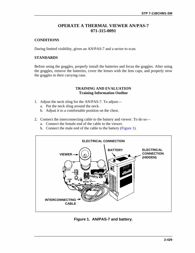
STP 7-11BCHM1-SM
2-429
OPERATE A THERMAL VIEWER AN/PAS-7 071-315-0091
CONDITIONS During limited visibility, given an AN/PAS-7 and a sector to scan. STANDARDS Before using the goggles, properly install the batteries and focus the goggles. After using the goggles, remove the batteries, cover the lenses with the lens caps, and properly stow the goggles in their carrying case.
TRAINING AND EVALUATION Training Information Outline
1. Adjust the neck sling for the AN/PAS-7. To adjust— a. Put the neck sling around the neck. b. Adjust it to a comfortable position on the chest. 2. Connect the interconnecting cable to the battery and viewer. To do so— a. Connect the female end of the cable to the viewer. b. Connect the male end of the cable to the battery (Figure 1).
ELECTRICALCONNECTION(HIDDEN)
BATTERYVIEWER
ELECTRICAL CONNECTION
INTERCONNECTINGCABLE
Figure 1. AN/PAS-7 and battery.

STP 7-11BCHM1-SM
2-430
CAUTIONBefore turning the power switch to the on position, be sure thatthe brightness control is fully counterclockwise.
3. Place the power switch in the ON position (Figure 2). (A faint ticking of the oscillating mirror can be heard.) Wait about 30 seconds after turn-on for the CRT (cathode ray tube) heater to warm up.
NEAR (8 METERS)
EYEPIECEFOCUS RING
ANDDIOPTER
SCALEBRIGHTNESS
FAR ( )
FOCUS
CONTRAST
POWERON-OFF
Figure 2. AN/PAS-7 controls.
4. Remove the lens cap from the infrared window (Figure 3).
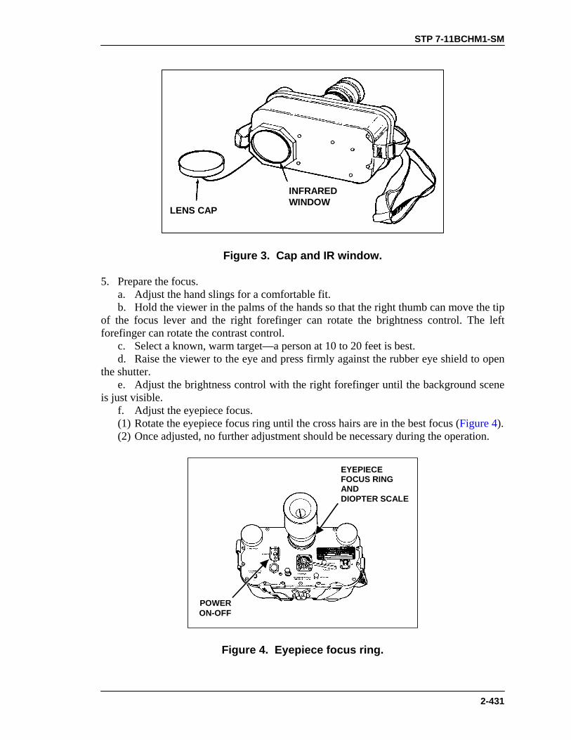
STP 7-11BCHM1-SM
2-431
INFRAREDWINDOW
LENS CAP
Figure 3. Cap and IR window.
5. Prepare the focus. a. Adjust the hand slings for a comfortable fit. b. Hold the viewer in the palms of the hands so that the right thumb can move the tip of the focus lever and the right forefinger can rotate the brightness control. The left forefinger can rotate the contrast control. c. Select a known, warm target—a person at 10 to 20 feet is best. d. Raise the viewer to the eye and press firmly against the rubber eye shield to open the shutter. e. Adjust the brightness control with the right forefinger until the background scene is just visible. f. Adjust the eyepiece focus. (1) Rotate the eyepiece focus ring until the cross hairs are in the best focus (Figure 4). (2) Once adjusted, no further adjustment should be necessary during the operation.
EYEPIECEFOCUS RINGANDDIOPTER SCALE
POWERON-OFF
Figure 4. Eyepiece focus ring.
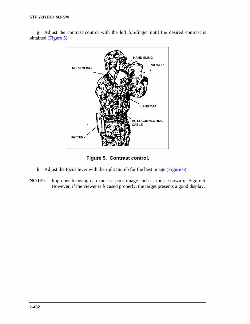
STP 7-11BCHM1-SM
2-432
g. Adjust the contrast control with the left forefinger until the desired contrast is obtained (Figure 5).
VIEWER
BATTERY
NECK SLING
INTERCONNECTINGCABLE
HAND SLING
LENS CAP
Figure 5. Contrast control.
h. Adjust the focus lever with the right thumb for the best image (Figure 6). NOTE: Improper focusing can cause a poor image such as those shown in Figure 6.
However, if the viewer is focused properly, the target presents a good display.
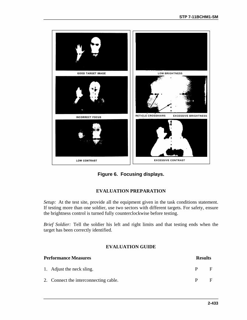
STP 7-11BCHM1-SM
2-433
RETICLE CROSSHAIRS EXCESSIVE BRIGHTNESS
LOW BRIGHTNESS
EXCESSIVE CONTRAST
Figure 6. Focusing displays.
EVALUATION PREPARATION
Setup: At the test site, provide all the equipment given in the task conditions statement. If testing more than one soldier, use two sectors with different targets. For safety, ensure the brightness control is turned fully counterclockwise before testing. Brief Soldier: Tell the soldier his left and right limits and that testing ends when the target has been correctly identified.
EVALUATION GUIDE
Performance Measures
Results
1. Adjust the neck sling.
P F
2. Connect the interconnecting cable.
P F

STP 7-11BCHM1-SM
2-434
EVALUATION GUIDE
Performance Measures
Results
3. Turn the brightness control fully counterclockwise.
P F
4. Place the power switch to ON and wait 30 seconds.
P F
5. Remove the cap from the infrared window.
P F
6. Adjust the hand slings.
P F
7. Hold the viewer.
P F
8. Rotate the eyepiece focus ring until the cross hairs are focused.
P F
9. Adjust the focus lever.
P F
10. Adjust the brightness and contrast control.
P F
11. Identify the target. P F
FEEDBACK
If the soldier passes all steps, score him GO. If he fails any steps, score him NO-GO, then show him what he did wrong and how to do it correctly.
REFERENCES
Required Related None TM 11-5855-246-10

STP 7-11BCHM1-SM
2-435
OPSEC AND COMSEC
IDENTIFY COMBAT VEHICLES 071-730-0012
CONDITIONS Given a classroom with a 35-mm slide projector and screen, forty 35-mm slides of combat vehicles as described in FM 23-34, Appendix I, a 12-second exposure time for each slide, a stopwatch, paper, and a pen or pencil. STANDARDS Identify thirty-six of forty vehicles by nomenclature as described in FM 23-34, Appendix I.
TRAINING AND EVALUATION Training Information Outline
1. Four areas of characteristics are used to identify vehicles. Most tanks have all four areas of characteristics, though not all vehicles do. a. Track and suspension system. Many tanks can be recognized by their track and suspension systems. However, recognizing a vehicle by this feature alone is often difficult. The tracks are often obscured by grass, dirt, terrain, dust, or other factors. To identify the track and suspension system, check to see whether it has support or return rollers. Few threat vehicles, except the T-10, T-64, T-72, BMD, BMP, SP-122, and SP-152, have either. (1) Characteristics of most threat vehicles include— • Flat (Christie) suspension system. • No support or return rollers. • No torsion bars. • Unevenly spaced road wheels. (2) Characteristics of most NATO vehicles include— • Suspended track. • Support or return rollers. • Torsion bars. • Evenly spaced road wheels. • Shock absorbers. b. Turret. Most turrets can be grouped into three categories: • Older model, big, bulky turrets. • New model well-sloped turrets. • New model streamlined turrets.
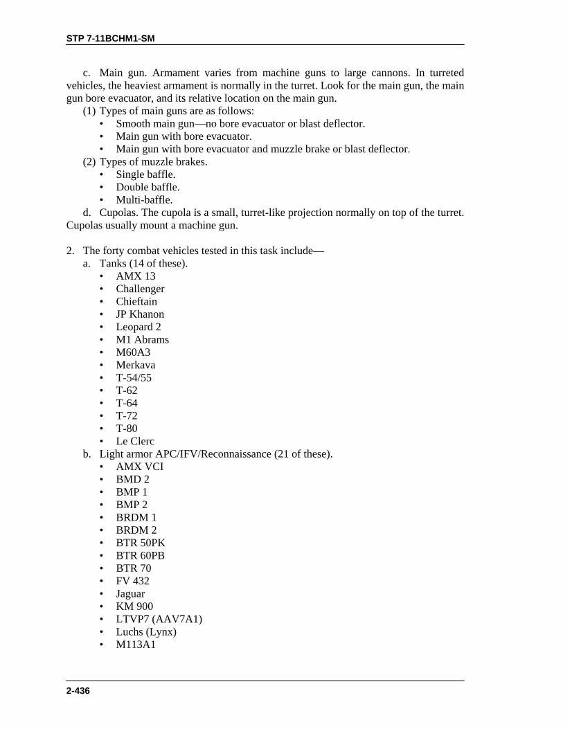
STP 7-11BCHM1-SM
2-436
c. Main gun. Armament varies from machine guns to large cannons. In turreted vehicles, the heaviest armament is normally in the turret. Look for the main gun, the main gun bore evacuator, and its relative location on the main gun. (1) Types of main guns are as follows: • Smooth main gun—no bore evacuator or blast deflector. • Main gun with bore evacuator. • Main gun with bore evacuator and muzzle brake or blast deflector. (2) Types of muzzle brakes. • Single baffle. • Double baffle. • Multi-baffle. d. Cupolas. The cupola is a small, turret-like projection normally on top of the turret. Cupolas usually mount a machine gun. 2. The forty combat vehicles tested in this task include— a. Tanks (14 of these). • AMX 13 • Challenger • Chieftain • JP Khanon • Leopard 2 • M1 Abrams • M60A3 • Merkava • T-54/55 • T-62 • T-64 • T-72 • T-80 • Le Clerc b. Light armor APC/IFV/Reconnaissance (21 of these). • AMX VCI • BMD 2 • BMP 1 • BMP 2 • BRDM 1 • BRDM 2 • BTR 50PK • BTR 60PB • BTR 70 • FV 432 • Jaguar • KM 900 • LTVP7 (AAV7A1) • Luchs (Lynx) • M113A1
STP 7-11BCHM1-SM
2-437
• M2/M3 Bradley • Marder • Scimitar • Scorpion • VAB • Warrior c. Antitank Systems (1 of these). • M901 (ITV) d. Antiaircraft (2 of these). • Gepard • ZSU 23-4 e. Miscellaneous (2 of these). • LAV 25 (wheeled reconnaissance) • M88 (mechanized recovery vehicle)
EVALUATION PREPARATION Setup: At the test site, provide the soldier(s) with all equipment and materials as stated in the conditions statement. Before evaluating the soldier(s), check the 35-mm projector to ensure that it is operational. Also, check to ensure that a spare bulb is readily available. Check the TEST SLIDES to ensure they are in the correct order (the same order as the answer key) and correct view (not turned around or upside down). • After evaluating each soldier(s), verify that the slides remain in the same order as
the answer key. This ensures accuracy in the event the equipment malfunctions, such as if it skips a slide.
• Allow student(s) twenty-two seconds for each performance measure: twelve
seconds to view the slide and ten seconds to mark his answer. Have student(s) mark his answers in his Identify Combat Vehicles handout.
Brief Soldier: Read the following instructions to the soldier(s):
“At this time, you will be evaluated on your ability to identify combat vehicles. You must identify thirty-six of forty vehicles by nomenclature. You will have twelve seconds to view each slide and ten seconds between each slide to write your answer. Be sure you do not get out of sequence, or your answers will be incorrect. When I say START, you will have twenty-two seconds to complete each task.”

STP 7-11BCHM1-SM
2-438
EVALUATION GUIDE Performance Measures
Results
1. Identify vehicle slide number 1.
P F
2. Identify vehicle slide number 2.
P F
3. Identify vehicle slide number 3.
P F
4. Identify vehicle slide number 4.
P F
5. Identify vehicle slide number 5.
P F
6. Identify vehicle slide number 6.
P F
7. Identify vehicle slide number 7.
P F
8. Identify vehicle slide number 8.
P F
9. Identify vehicle slide number 9.
P F
10. Identify vehicle slide number 10.
P F
11. Identify vehicle slide number 11.
P F
12. Identify vehicle slide number 12.
P F
13. Identify vehicle slide number 13.
P F
14. Identify vehicle slide number 14.
P F
15. Identify vehicle slide number 15.
P F
16. Identify vehicle slide number 16.
P F
17. Identify vehicle slide number 17.
P F
18. Identify vehicle slide number 18.
P F
19. Identify vehicle slide number 19.
P F
20. Identify vehicle slide number 20.
P F
21. Identify vehicle slide number 21.
P F

STP 7-11BCHM1-SM
2-439
EVALUATION GUIDE Performance Measures
Results
22. Identify vehicle slide number 22.
P F
23. Identify vehicle slide number 23.
P F
24. Identify vehicle slide number 24.
P F
25. Identify vehicle slide number 25.
P F
26. Identify vehicle slide number 26.
P F
27. Identify vehicle slide number 27.
P F
28. Identify vehicle slide number 28.
P F
29. Identify vehicle slide number 29.
P F
30. Identify vehicle slide number 30.
P F
31. Identify vehicle slide number 31.
P F
32. Identify vehicle slide number 32.
P F
33. Identify vehicle slide number 33.
P F
34. Identify vehicle slide number 34.
P F
35. Identify vehicle slide number 35.
P F
36. Identify vehicle slide number 36.
P F
37. Identify vehicle slide number 37.
P F
38. Identify vehicle slide number 38.
P F
39. Identify vehicle slide number 39.
P F
40. Identify vehicle slide number 40.
P F
STP 7-11BCHM1-SM
2-440
FEEDBACK
1. Score the soldier’s answer sheet and use it for his individual critique. Transfer his score onto the student evaluation handout.
2. Circle the P (Pass) beside each performance measure the soldier identified correctly.
Circle the F (Fail) beside each performance measure the soldier identified incorrectly. For subsequent (second and third) tests, circle only the F (Fail) beside each performance measure that the soldier identified incorrectly. For any F (Failed) performance measures, write the nomenclature of the vehicle incorrectly identified in the space provided.
3. Score the soldier an overall GO if he passed at least thirty-six performance measures.
Circle the GO under the appropriate first, second, or third test. Place your initials under the score.
4. Score the soldier an overall NO-GO if he failed more than five performance
measures. Circle the NO-GO under the appropriate first, second, or third test. Place your initials under the score.
5. If the soldier failed any performance measures, show him the vehicle incorrectly
identified and explain how to identify it correctly. 6. If the soldier received a NO-GO, he will be provided with retraining and practice on
the vehicles that he failed. Upon completion of the soldier’s retraining, that instructor will place his (the instructor’s) initials under the appropriate first or second retrain/practice.
REFERENCES
Required Related FM 23-34 None FM 71-1 GTA 17-2-11 GTA 17-2-13
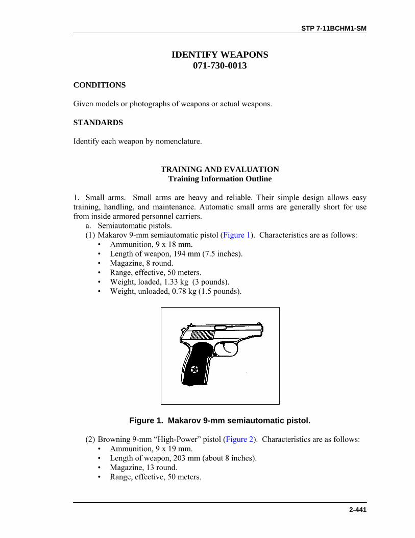
STP 7-11BCHM1-SM
2-441
IDENTIFY WEAPONS 071-730-0013
CONDITIONS Given models or photographs of weapons or actual weapons. STANDARDS Identify each weapon by nomenclature.
TRAINING AND EVALUATION Training Information Outline
1. Small arms. Small arms are heavy and reliable. Their simple design allows easy training, handling, and maintenance. Automatic small arms are generally short for use from inside armored personnel carriers. a. Semiautomatic pistols. (1) Makarov 9-mm semiautomatic pistol (Figure 1). Characteristics are as follows: • Ammunition, 9 x 18 mm. • Length of weapon, 194 mm (7.5 inches). • Magazine, 8 round. • Range, effective, 50 meters. • Weight, loaded, 1.33 kg (3 pounds). • Weight, unloaded, 0.78 kg (1.5 pounds).
Figure 1. Makarov 9-mm semiautomatic pistol.
(2) Browning 9-mm “High-Power” pistol (Figure 2). Characteristics are as follows: • Ammunition, 9 x 19 mm. • Length of weapon, 203 mm (about 8 inches). • Magazine, 13 round. • Range, effective, 50 meters.
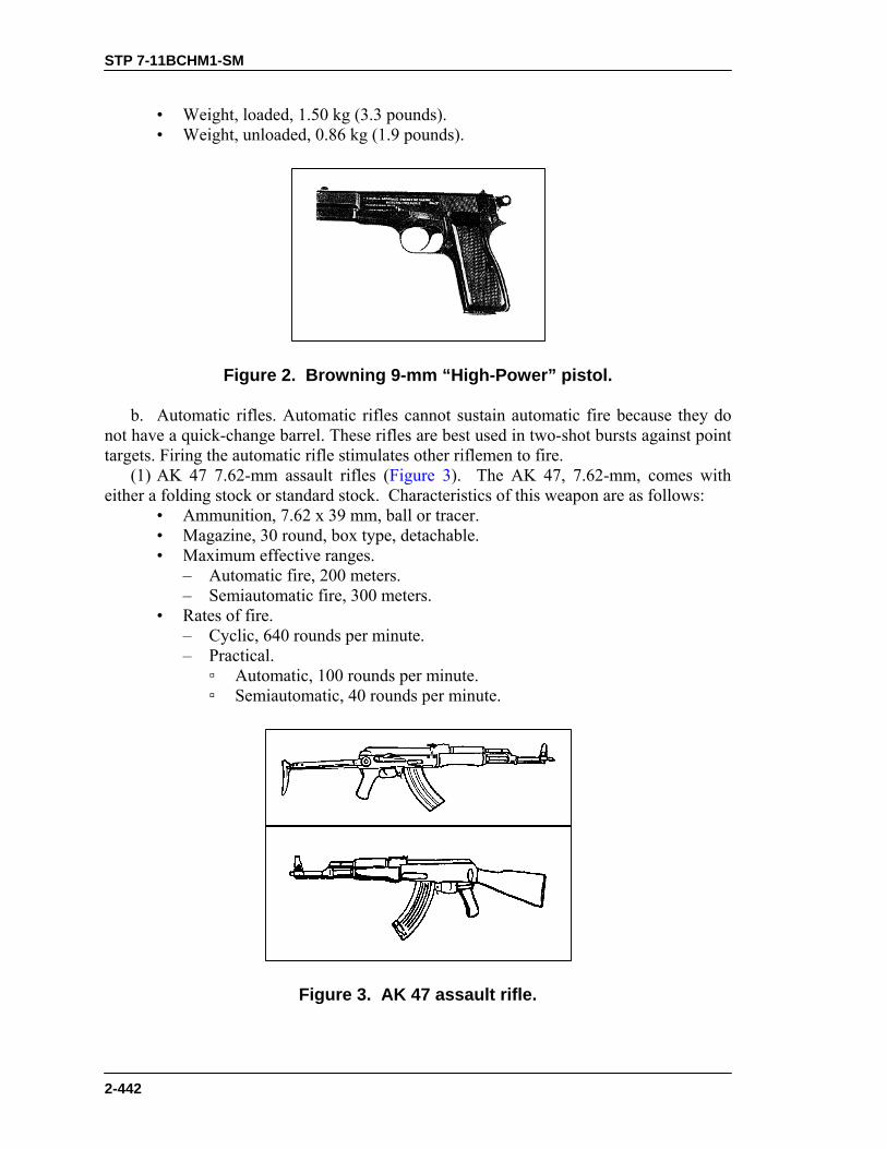
STP 7-11BCHM1-SM
2-442
• Weight, loaded, 1.50 kg (3.3 pounds). • Weight, unloaded, 0.86 kg (1.9 pounds).
Figure 2. Browning 9-mm “High-Power” pistol.
b. Automatic rifles. Automatic rifles cannot sustain automatic fire because they do not have a quick-change barrel. These rifles are best used in two-shot bursts against point targets. Firing the automatic rifle stimulates other riflemen to fire. (1) AK 47 7.62-mm assault rifles (Figure 3). The AK 47, 7.62-mm, comes with either a folding stock or standard stock. Characteristics of this weapon are as follows: • Ammunition, 7.62 x 39 mm, ball or tracer. • Magazine, 30 round, box type, detachable. • Maximum effective ranges. – Automatic fire, 200 meters. – Semiautomatic fire, 300 meters. • Rates of fire. – Cyclic, 640 rounds per minute. – Practical. ▫ Automatic, 100 rounds per minute. ▫ Semiautomatic, 40 rounds per minute.
Figure 3. AK 47 assault rifle.

STP 7-11BCHM1-SM
2-443
(2) AK 74 5.45-mm assault rifle (Figure 4). The AK 74 may have either a wooden or skeleton stock and looks like an AKM with a muzzle brake. You may find more information about this weapon on the Internet at http://www.prairienet.org/guns/arms/ak47.htm.
Characteristics of this weapon are as follows: • Ammunition, 5.45 x 39 mm. • Length (wooden stock model), 930 mm (36.6 inches). • Length (folding stock model with stock folded), 690 mm (27.2 inches). • Magazine, curved plastic, 30 round. • Muzzle velocity, 900 mps (1,984 fps). • Operation, gas, selective fire. • Rate of fire, cyclic, 650 rounds per minute. • Range, effective, 400 meters. • Recognizable feature, “Ak-ak” sound when fired. • Weight, unloaded, 3.6 kg (7.9 pounds).
Figure 4. AK 74 5.45-mm assault rifle.
(3) SKS 7.62-mm x 39-mm semiautomatic carbine (Figure 5). • Ammunition, 7.62-mm M43 cartridge. • Length, 1.02 meters (40.2 inches). • Magazine, integral, 10 round, triangular. • Operation, gas, semiautomatic. • Range, effective, 400 meters. • Sights, day. – Front, hooded sight post. – Rear, adjustable from 100 to 1,000 meters. • Weight, unloaded, 3.8 kg (8.4 pounds). • Recognizable features. – Integral triangular magazine. – Gas port cylinder above the barrel. – Knife-type bayonet. – Hooded front sight post.

STP 7-11BCHM1-SM
2-444
Figure 5. SKS 7.62-mm x 39-mm semiautomatic carbine.
(4) M-52/57 7.62-mm semiautomatic rifle (Figure 6). Characteristics of the M52/57 are as follows: • Ammunition, 7.62-mm M43 cartridge. • Length, 1 meter. • Magazine, integral, 10 round, box type. • Operation, gas, semiautomatic. • Range, effective, 400 meters. • Sights, day. – Front hooded sight post. – Rear, adjustable from 100 to 900 meters. • Weight, unloaded, 4.45 kg (9.8 pounds). • Recognizable features. – Gas port cylinder above the barrel. – Folding, knife-type bayonet. – Hooded front sight post.
Figure 6. M-52/57 7.62-mm semiautomatic rifle.
(5) M14A2 .30 caliber automatic rifle (Figure 7). Characteristics of the M14A2 are as follows: • Ammunition, 7.62 x 51 mm. • Magazine, 20 round, box type. • Rate of fire, 700 to 750 rounds per minute. • Sight, day, 10X scope, adjustable focus.

STP 7-11BCHM1-SM
2-445
Figure 7. M14A2 .30 caliber automatic rifle.
(6) FN FAL 7.62-mm assault rifle (Figure 8). Characteristics of the FN FAL are as follows: • Ammunition, 7.62-mm. • Length, 1,054 mm (41.5 inches). • Magazine, 20 round, box type. • Muzzle velocity, 2,800 fps (853 mps). • Operation, gas, semiautomatic or automatic. • Range, effective, 600 meters. • Sight, day, rear, adjustable, 600-meter (656-yard). • Weight, unloaded, 4.31 kg (9.5 pounds). • Recognizable features. – Folding carrying handle forward of receiver. – Solid or folding stock. – Bipod and heavier barrel on automatic version.
Figure 8. FN FAL 7.62-mm assault rifle.
c. Sniper rifles. (1) SVD 7.62-mm sniper rifle Dragonou (Figure 9). Characteristics of the SVD 7.62-mm sniper rifle Dragonou are as follows: • Ammunition, 7.62 x 54-mm M-08 cartridge. • Sight, day, rear, adjustable, 1,300-meter; or 4X scope. • Length of weapon, 1.225 meters. • Magazine, 10 round, box type, detachable. • Maximum effective range, 1,300 meters. • Operation, gas, semiautomatic. • Weight, unloaded, 4.3 kg (9.5 pounds).
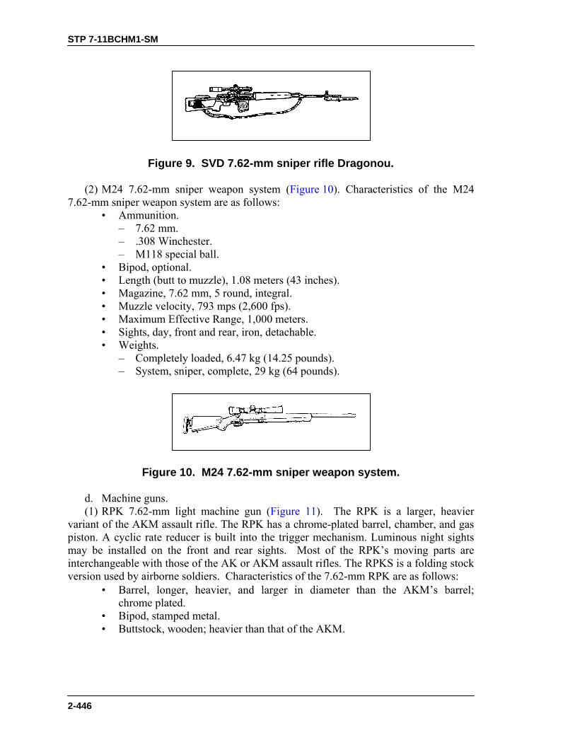
STP 7-11BCHM1-SM
2-446
Figure 9. SVD 7.62-mm sniper rifle Dragonou.
(2) M24 7.62-mm sniper weapon system (Figure 10). Characteristics of the M24 7.62-mm sniper weapon system are as follows: • Ammunition. – 7.62 mm. – .308 Winchester. – M118 special ball. • Bipod, optional. • Length (butt to muzzle), 1.08 meters (43 inches). • Magazine, 7.62 mm, 5 round, integral. • Muzzle velocity, 793 mps (2,600 fps). • Maximum Effective Range, 1,000 meters. • Sights, day, front and rear, iron, detachable. • Weights. – Completely loaded, 6.47 kg (14.25 pounds). – System, sniper, complete, 29 kg (64 pounds).
Figure 10. M24 7.62-mm sniper weapon system.
d. Machine guns. (1) RPK 7.62-mm light machine gun (Figure 11). The RPK is a larger, heavier variant of the AKM assault rifle. The RPK has a chrome-plated barrel, chamber, and gas piston. A cyclic rate reducer is built into the trigger mechanism. Luminous night sights may be installed on the front and rear sights. Most of the RPK’s moving parts are interchangeable with those of the AK or AKM assault rifles. The RPKS is a folding stock version used by airborne soldiers. Characteristics of the 7.62-mm RPK are as follows: • Barrel, longer, heavier, and larger in diameter than the AKM’s barrel;
chrome plated. • Bipod, stamped metal. • Buttstock, wooden; heavier than that of the AKM.

STP 7-11BCHM1-SM
2-447
• Magazine. – 40 round, curved box type. – 75 round, spring-loaded, drum type. – 30 round, curved, box type (AKM magazine). • Nightsight, infrared, compatible with some RPKs, but not all. • Receiver, modified from the AKM receiver to fit the larger-diameter barrel.
Figure 11. RPK 7.62-mm light machine gun.
(2) RPK-74 5.45-mm light machine gun (Figure 12). Characteristics of the 5.45-mm RPK LMG are as follows: • Ammunition, 5.45 x 39-mm, ball or tracer. • Magazine, 30 or 40 round, box type, detachable. • Maximum effective range, 800 meters. • Rates of fire. – Cyclic, 800 rounds per minute. – Practical. ▫ Automatic, 150 rounds per minute. ▫ Semiautomatic, 50 rounds per minute. • Nightsight, optional image-intensifying sight.
Figure 12. RPK 5.45-mm light machine gun.
(3) PKM 7.62-mm general-purpose machine gun (Figure 13). Characteristics of the PKM are as follows: • Ammunition, 7.62 x 54 mm. – Ball. – Tracer. – AP. – API. • Crew, two. • Feed mechanism, 100-, 200-, or 300-round belt.

STP 7-11BCHM1-SM
2-448
• Maximum effective range, 1,000 meters. • Maximum range, 3,800 meters. • Nightsight, image intensifier. • Rates of fire. – Cyclic, 650 rd/min. – Effective, 250rd/min • Unit of fire, 2,500.
Figure 13. PKM general-purpose machine gun.
(4) FN MAG 58 general purpose 7.62-mm machine gun (Figure 14). Characteristics of the FN MAG 58 general purpose 7.62-mm machine gun are as follows: • Action, air-cooled, gas-operated. • Ammunition, 7.62 x 51 mm. • Barrel, quick-change. • Bipod, built-in (weapon may be fired from tripod also). • Feeding mechanism, belt. • Operation, gas, air-cooled. • Range, effective, 1,500 meters. • Rate of fire, cyclic, 650 to 1,500 rounds per minute. • Weights. – Loaded, 13.92 kg (30.69 pounds). – Unloaded, 10.98 kg (24.21 pounds). • Recognizable features. – Gas regulator above bipod. – Numerous rounded rivet heads along the receiver body.

STP 7-11BCHM1-SM
2-449
Figure 14. FN MAG general purpose machine gun.
2. Antitank weapons. a. Grenade launchers. (1) RPGs (rocket-propelled grenades) (Figure 15). Characteristics of RPGs are as follows: • Action, smooth-bore, muzzle-loading, recoilless shoulder weapon. • Ammunition, 40 to 73 mm. • Fin-stabilized. • Shaped-charge. • Antitank and antipersonnel HEAT grenades. • Caliber, warhead is at least 80-mm (3.15 inches) in diameter. • Diameter, launch tube, 40 mm (1.6 inches). • Length, 950 mm (37.4 inches). • Penetration, 175 to 320 mm (6.9 to 12.6 inches). • Range, maximum effective, 150 meters (moving target) to 300 meters
(static target). • Rate of fire, four to six rounds per minute. • Sights. – Night, infrared sight. – Day, front, fixed sight post. – Day, rear, adjustable folding leaf type. • Recognizable features. – Large cone-tipped round. – Muzzle-loader. – Pistol grip trigger assembly. – Possible aluminum blast deflector at rear of weapon. – Steel barrel open at both ends. – Sight, rear, top-mounted, adjustable leaf. – Sight, front, top-mounted, fixed. – Two-piece plywood heat shield at midsection.

STP 7-11BCHM1-SM
2-450
RPG 7
RPG 18
RPG 16
Figure 15. RPG.
(2) M203 grenade launcher (Figure 16). Characteristics of the M203 are as follows: • Action, single shot, breech loading, pump action (sliding barrel). • Ammunition, 40-mm grenades (HE, HEDP, CS, TP, smoke, and illumination). • Chamber pressure, 210 kg/cm. • Combat load, minimum, 36 HE rounds. • Sights, day. – Front sight post. – Rear leaf sight. • Length of rifle and grenade launcher, overall—9 cm (39 inches). • Muzzle velocity, 76 mps (250 fps). • Ranges. – Effective, about 400 meters (1,312 feet or 437.3 yards). – Maximum effective, fire-team-sized target, 350 meters (1,148 feet). – Maximum effective, vehicle or weapon point target, 150 meters (492 feet). – Minimum arming, about 14 to 38 meters (46 to 125 feet). – Minimum safe, HE, combat, 31 meters (102 feet or 34 yards). – Minimum safe, HE, training, 80 meters (262.4 feet or 87.5 yards). • Weights. – Unloaded, unmounted grenade launcher, 1.4 kg (3.1 pounds). – Loaded rifle and grenade launcher, 5.0 kg (11 pounds). • Round, about 227 grams (8 ounces). • Rate of fire, 5 to 7 rounds per minute.
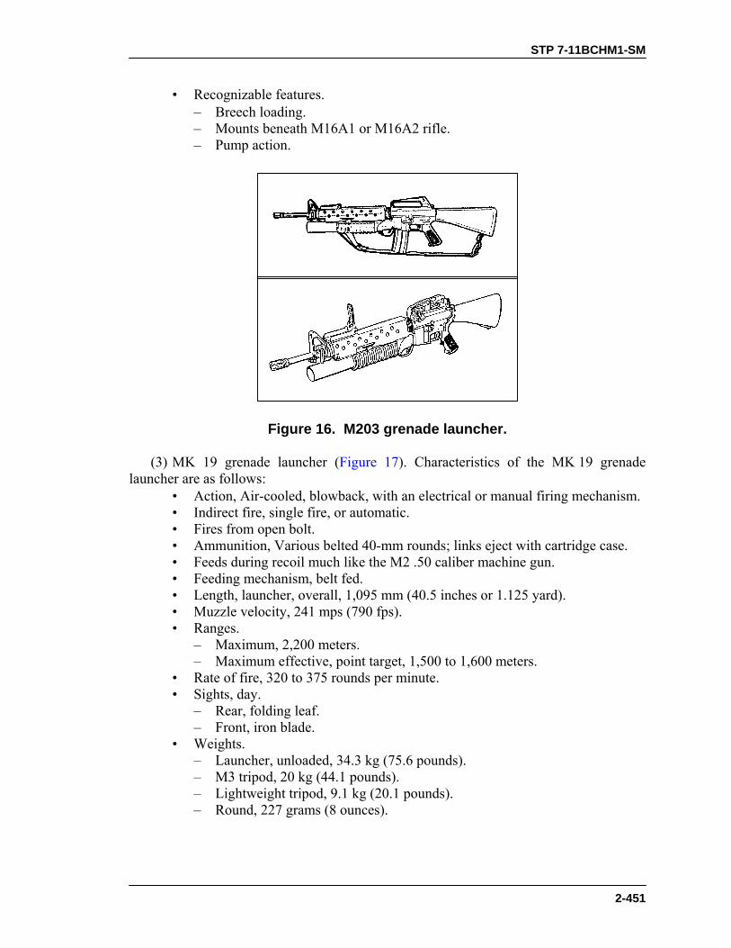
STP 7-11BCHM1-SM
2-451
• Recognizable features. – Breech loading. – Mounts beneath M16A1 or M16A2 rifle. – Pump action.
Figure 16. M203 grenade launcher.
(3) MK 19 grenade launcher (Figure 17). Characteristics of the MK 19 grenade launcher are as follows: • Action, Air-cooled, blowback, with an electrical or manual firing mechanism. • Indirect fire, single fire, or automatic. • Fires from open bolt. • Ammunition, Various belted 40-mm rounds; links eject with cartridge case. • Feeds during recoil much like the M2 .50 caliber machine gun. • Feeding mechanism, belt fed. • Length, launcher, overall, 1,095 mm (40.5 inches or 1.125 yard). • Muzzle velocity, 241 mps (790 fps). • Ranges. – Maximum, 2,200 meters. – Maximum effective, point target, 1,500 to 1,600 meters. • Rate of fire, 320 to 375 rounds per minute. • Sights, day. – Rear, folding leaf. – Front, iron blade. • Weights. – Launcher, unloaded, 34.3 kg (75.6 pounds). – M3 tripod, 20 kg (44.1 pounds). – Lightweight tripod, 9.1 kg (20.1 pounds). – Round, 227 grams (8 ounces).

STP 7-11BCHM1-SM
2-452
• Recognizable features. – Sight, rear adjustable. – Tripod, mounts forward under the receiver. – Short, boxy receiver. – Heavy barrel with flash suppressor.
Figure 17. MK 19 grenade launcher.
(4) M79 grenade launcher (Figure 18). Characteristics of the M79 grenade launcher are as follows: • Action, break open, single shot, shoulder fired. • Ammunition, 40 mm. • Sights, day. – Rear, folding leaf. – Front, iron blade. • Length, launcher, overall, 73.7 cm (29 inches). • Muzzle velocity, 76 mps (250 fps). • Ranges. – Maximum, 400 meters (1,312 feet or 437.3 yards). – Maximum effective, fire-team sized area target, 350 meters (1,148 feet). – Maximum effective, vehicle or weapon point target, 150 meters (492 feet). – Minimum safe firing, HE, combat , 31 meters (102 feet or 34 yards). – Minimum safe firing, HE, training, 130 meters (426 feet or 142 yards). • Recognizable features. – Adjustable rear sight located in center of barrel. – Short, wide-bore barrel. • Weights. – Round, 227 grams (8 ounces). – Weapon, unloaded, 2.72 kg (6 pounds). – Weapon, loaded, 2.95 kg (6.5 pounds).
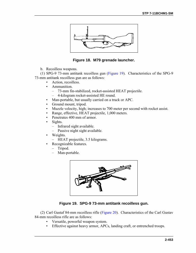
STP 7-11BCHM1-SM
2-453
Figure 18. M79 grenade launcher.
b. Recoilless weapons. (1) SPG-9 73-mm antitank recoilless gun (Figure 19). Characteristics of the SPG-9 73-mm antitank recoilless gun are as follows: • Action, recoilless. • Ammunition. – 73-mm fin-stabilized, rocket-assisted HEAT projectile. – 4-kilogram rocket-assisted HE round. • Man-portable, but usually carried on a truck or APC. • Ground mount, tripod. • Muzzle velocity, high; increases to 700 meter per second with rocket assist. • Range, effective, HEAT projectile, 1,000 meters. • Penetrates 400 mm of armor. • Sights. – Infrared sight available. – Passive night sight available. • Weights. – HEAT projectile, 3.5 kilograms. • Recognizable features. – Tripod. – Man-portable.
Figure 19. SPG-9 73-mm antitank recoilless gun.
(2) Carl Gustaf 84-mm recoilless rifle (Figure 20). Characteristics of the Carl Gustav 84-mm recoilless rifle are as follows: • Versatile, powerful weapon system. • Effective against heavy armor, APCs, landing craft, or entrenched troops.

STP 7-11BCHM1-SM
2-454
• Ammunition. – HEAT 751 penetrates tiles without setting them off, then blasts through
armor into interior. – HEAT 551 is effective against armor vehicles and other hard targets to
700 meters. – TP 552 is an inert warhead for training and practice; it is ballistically
matched to HEAT 551 round. – HEDP 502 is an dual-purpose HE and HEAT round for urban combat.
Effective against light armored vehicles, concrete and brick walls, field fortifications, and ground forces. In the HEAT role, the round has a devastating behind-armor effect.
– HE 441B can be set to impact detonation or air burst; used to combat troops in the open or behind cover, soft-skinned vehicles, and other soft targets.
– Illumination 545 rapidly illuminates target areas. – Smoke 469B develops a smoke screen instantly on impact.
Figure 20. Carl Gustav 84-mm recoilless rifle.
c. Guided missiles. (1) Sagger or Swatter with carrying case and mount (Figure 21). (a) Characteristics common to the Sagger and Swatter. • Sights. Optical viewer for tracking target and missile (day only). • Employment. Employed on the ground while the crew is “buttoned up” or
mounted on a BMP, BMD, BRDM-2, or helicopter. • Target. Can defeat most known armor. • Gunners. Must be highly trained, because they must track the target and the
missile through an optical viewer at the same time they fly the missile with a joystick.
• Missile speed. Sagger and Swatter missiles are slower than the TOW.

STP 7-11BCHM1-SM
2-455
• Night use. Neither the Sagger nor the Swatter may be used at night; they have no night vision capability.
• Vulnerabilities. – Wire breakage. Bushes and other obstacles may break wires. – Early detonation of warhead. Trees or heavy brush can detonate the
ATGM warhead. (b) Distinguishing characteristics of the Sagger. • Tracking, optical (same as Swatter). • Wire guided. • Minimum tracking range, 500 meters (same as Swatter). • Maximum effective range, 3,000 meters (slightly more accurate at this range
than the Sagger). • Invulnerable to electronic countermeasures. • Highly mobile. • Weight, 11.3 kg. • Dimensions. – Length, 864 mm. – Diameter, 120-mm. (c) Distinguishing characteristics of the Swatter. • Tracking, optical (same as Sagger). • Radio guided. • Minimum tracking range, 500 meters (same as Sagger). • Maximum effective range, 3,000 meters (slightly less accurate at this range
than the Sagger). • Vulnerable to electronic countermeasures. • Slightly less mobile than the Sagger. • Dimensions unknown. • Weight unknown.
Figure 21. Sagger or Swatter with carrying case and mount.
(2) TOW 2 (BGM-71D) heavy antitank weapon (Figure 22). Characteristics of the TOW 2 (BGM-71D) heavy antitank weapon are as follows: • Employment by ground or vehicle mount. • Range, 3,750 feet (0.71 mile).

STP 7-11BCHM1-SM
2-456
• Ammunition, four configurations. • Weight, 190.5 lb, complete.
Figure 22. TOW 2 (BGM-71D) heavy antitank weapon.
(3) M136 AT4 light antiarmor weapon (Figure 23). Characteristics of the M136 AT4 are as follows: • Ammunition, integral, rocket-type 84-mm cartridge. • Caliber, 84 mm. • Length of launcher, 1.02 meters (40 inches). • Length of rocket, 460 mm (18 inches or 0.5 yard). • Penetration, more than 14 inches of armor. • Ranges. – Maximum, 2,100 meters (1.3 mile). – Maximum effective, 300 meters. • Weights. – Loaded, 8.5 kg (18.8 pounds). – Unloaded, 6.7 kg (14.8 pounds).
Figure 23. M136 AT4 light antiarmor weapon.
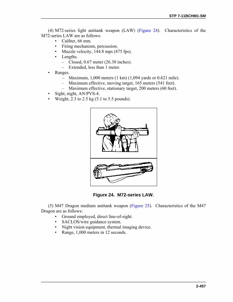
STP 7-11BCHM1-SM
2-457
(4) M72-series light antitank weapon (LAW) (Figure 24). Characteristics of the M72-series LAW are as follows: • Caliber, 66 mm. • Firing mechanism, percussion. • Muzzle velocity, 144.8 mps (475 fps). • Lengths. – Closed, 0.67 meter (26.38 inches). – Extended, less than 1 meter. • Ranges. – Maximum, 1,000 meters (1 km) (1,094 yards or 0.621 mile). – Maximum effective, moving target, 165 meters (541 feet). – Maximum effective, stationary target, 200 meters (60 feet). • Sight, night, AN/PVS-4. • Weight, 2.3 to 2.5 kg (5.1 to 5.5 pounds).
Figure 24. M72-series LAW.
(5) M47 Dragon medium antitank weapon (Figure 25). Characteristics of the M47 Dragon are as follows: • Ground employed, direct line-of-sight. • SACLOS/wire guidance system. • Night vision equipment, thermal imaging device. • Range, 1,000 meters in 12 seconds.

STP 7-11BCHM1-SM
2-458
Figure 25. M47 Dragon medium antitank weapon.
d. Grenade launchers. The only weapon included in this category for purposes of this task is the AGS-17 automatic 30-mm grenade launcher (Figure 26). Characteristics of the AGS-17 automatic 30-mm grenade launcher are as follows: • Action, selective-fire mode. • Ammunition includes 30 x 28.5-mm fragmentary, HE, and possibly
HEAT also. – Bursting radius, 7 meters. – Crew, three. – Length of weapon, 0.80 meter. • Magazine, 29 round, belt fed. • Ranges, effective. – Direct, 1,200 meters. – Indirect, 1,730 meters. • Rate of fire. – Cyclic, 300 to 350 rds/min. – Effective, 40 to 60 rds/min. • Unit of fire, eighty-seven. • Weight of weapon. – Loaded, 43 kg. – Unloaded, 17.75 kg.
Figure 26. AGS-17 automatic 30-mm grenade launcher.

STP 7-11BCHM1-SM
2-459
e. Artillery. (1) D-20 152-mm gun/howitzer (Figure 27). The D-20’s range compensates for its cumbersome nature—it is large, and it is too heavy for a simple towed carriage. Other characteristics of the D-20 are as follows: (a) Ammunition. The D-20 uses case-type, variable-charge, separate-loading ammunition. • Frag-HE. • CP. • AP-T. • HE/RAP. • HEAT. • HEAT-SS (spin stabilized). • Flechette. • Scatterable mines (AT and AP). • Semi-active laser. • Chemical (CW agent dispersed by a TNT bursting charge). – The 40-kg round has 2.8 kg of the Sarin CW agent. – The 42.5-kg round has a 152-mm viscous Lewisite projectile and includes
5.4 kg CW agent. • Smoke (D-540). • Illuminating (S-540). • Tactical nuclear (0.2 kiloton). (b) Ranges. • Semi-active laser, 18 kilometers. • HE/RAP, 24 kilometers.
Figure 27. D-20 152-mm gun/howitzer.
(2) D-30. 122-mm howitzer (Figure 28). Characteristics of the D-30 are as follows: • Ammunition, variable charge, case type, separate loading. – Chemical, CW agent is dispersed by a TNT bursting charge. – 1.3 kg of Sarin CW in a 22.5 kg round. – 3.3 kg of viscous Lewisite CW in a 23.1 kg round (122-mm projectile). – Flechette. – Fragmentary-HE. – HEAT-FS. – Illuminating, S-462, weighs 22.4 kg. – Incendiary.

STP 7-11BCHM1-SM
2-460
– Leaflet. – RAP (maximum range 21,900 meters). – Smoke, D-462, weighs 22.3 kg. • Angle of fire, high to low. • Crew, eight. • Sights. – Infrared sight available. – Passive night vision sight available. • Tactical employment, antitank defense. • Traverse, 360 degrees. • Vulnerabilities include minimum crew protection. NOTE: Aligning the D-30 directly over the support rails reduces the weapon’s
maximum effective range significantly (to 7,000 meters).
Figure 28. D-30 122-mm howitzer.
EVALUATION PREPARATION Setup: At the test site, provide a model or a photograph of each weapon in this task to the soldier for 10 seconds. If photographs or models cannot be obtained, use the illustrations in this task. Brief Soldier: Tell the soldier that photographs or illustrations of weapons will be shown to him for 10 seconds each. During the 10-second viewing, the soldier must give the nomenclature of that weapon.
EVALUATION GUIDE Performance Measure
Results
IDENTIFY __ out of __ weapons by nomenclature.
P
F

STP 7-11BCHM1-SM
2-461
FEEDBACK If the soldier passes all steps, score him GO. If he fails any steps, score him NO-GO, then show him what he did wrong and how to do it correctly.
REFERENCES Required Related None FM 7-8 FM 71-1

STP 7-11BCHM1-SM
2-462
EMPLOY FIELD-EXPEDIENT EARLY WARNING DEVICES 071-730-0008
CONDITIONS Given dry gravel, dry vegetation, smoke and concussion grenades, cans, cloth strips, brass ammunition casings, trip wire, and paint. STANDARDS When activated, the devices attract attention by sound or sight.
TRAINING AND EVALUATION
Training Information Outline 1. Creative field-expedient devices are usually noisemakers and rely on inventiveness. The ones in this task summary are some commonly used examples. 2. The two types of field-expedient early warning devices are ground and container. a. The ground type consists of dry vegetation or gravel placed on a dry location or hole so that anyone stepping on it will make noise. (1) Select an area for placement that cannot be bypassed without drawing attention. (2) Choose an area large enough that it cannot be stepped over or jumped over easily or quietly. (3) Spread dry leaves and twigs or gravel in the area selected. (4) Test the device. Have one man position himself in the OP or fighting position. Have someone else activate the device. If nothing can be heard, move the device closer to the OP or fighting position. b. The container type usually consists of a container, a trip wire, a noisemaker, and an attachment device. (1) Use a metal cola, food, or ammunition container, or any other container that will produce noise if it is shaken with a rock, expended cartridge case, marble, or other noisemaker in it. (2) The trip wire is no more than 40 feet long. Place it about 18 inches above the ground, and anchor it securely on each end. (3) Punch holes in the sides and in the bottom of the container to reduce wind movement and to allow water to drain. (4) Securely attach the container to the trip wire. More than one container can be attached. (5) If barbed wire is emplaced, attach containers to several of the strands. c. The devices should be tested to ensure they work properly. (1) One man activates the device while another listens and observes from the position the device protects.

STP 7-11BCHM1-SM
2-463
(2) If nothing can be seen or heard, move the device closer. d. All devices should be concealed or camouflaged. 3. Field-expedient early warning devices can be constructed using smoke and concussion grenades and trip wire. a. Position smoke grenades so they do not obscure the view of the personnel or vehicle that activates the device. b. Place concussion grenades on the enemy side of a large tree, rock, or other object that will protect the defender from the effects of the blast.
EVALUATION PREPARATION Setup: At the test site, provide a defensive position with appropriate avenues of approach and the materials and equipment given in the task conditions statement. Brief Soldier: Tell the soldier to prepare three early warning devices, one ground type, one container type, and one using a smoke or concussion grenade.
EVALUATION GUIDE Performance Measures
Results
1. Emplace a ground-type device. a. Select an appropriate area for the device. b. Apply the noisemaker to the ground. c. Ensure the device cannot be bypassed without detection. d. Test the device for effectiveness.
P F
2. Emplace a container-type device. a. Select an appropriate area for the device.
P F
b. Put holes in the sides and bottom of the container. c. Attach the container to a trip wire or to barbed wire. d. Put the trip wire (if used) about 18 inches above the ground. e. Test the device for effectiveness.
3. Emplace a grenade-type device. a. Place smoke grenades where they will not block the defender’s view of the enemy activating the device.
P F
b. Place concussion grenades on the enemy side of a tree, rock, or other object.
c. Use trip wire no longer than 40 feet. d. Put the trip wire about 18 inches above the ground. e. Align the safety pin in the direct line of pull of the trip wire.

STP 7-11BCHM1-SM
2-464
FEEDBACK If the soldier passes all steps, score him GO. If he fails any steps, score him NO-GO, then show him what he did wrong and how to do it correctly.
REFERENCES Required Related None FM 5-250 FM 5-34

STP 7-11BCHM1-SM
2-465
RADIO
PREPARE SINCGARS (MANPACK) FOR OPERATION 113-587-1064
CONDITIONS Given a receiver-transmitter (RT) RT-1523, antenna AS-3693/PRC, handset H-250/U, battery box CY-8523A/PRC, battery BA-5590/U, and field pack (nylon large). STANDARDS Inspect components for serviceability. Assemble components, perform radio function check, and load required frequencies so that the radio can be used to communicate during operations.
TRAINING AND EVALUATION Training Information Outline
1. Inspect components. a. Inspect RT, antenna, handset, and ANCD or ICOM with cable for dirt or damage. b. Inspect the battery for damage, corrosion, or leakage. c. Clean or replace as required. Report damaged equipment to supervisor. 2. Install components. a. Install battery.
WARNINGThe lithium battery used with this equipment contains hazardousmaterials. To prevent personal injury or equipment damage—• DO NOT heat, incinerate, crush, puncture, disassemble, or
otherwise mutilate the battery.• DO NOT short-circuit, recharge, or bypass internal fuzes.• DO NOT store the battery in the equipment.• DO NOT place used batteries in ordinary trash. Turn them in
through supply channels.• TURN OFF equipment and leave the area immediately if you
feel the battery case becoming very hot, if you hear a batteryhissing or burping, or if you detect a rotten-egg smell.
• REMOVE the battery only after it cools.
(1) Stand the RT on the front panel guards. Place the battery box on the bottom of the RT, aligning the box systems connector with the RT systems connector.

STP 7-11BCHM1-SM
2-466
(2) If installing a used battery, check the tag or decal on the battery, and note battery life condition numbers. (3) Place the battery in the battery box and mate the connectors. Close the battery box cover and secure the hold-down latches. (4) Set battery life condition. (a) Set the FCTN switch to LD. (b) If the battery is new, use the keyboard to enter the number “00.” If the battery you installed is not new, enter the number on the tag or decal. (c) Press BATT/CALL—the display will show “00.” (d) Press CLR—the display will show two lines. (e) Press number buttons—enter “00” for new battery. On a used battery, enter the two-digit number for the number of hours the battery was used, for example, “03” for three hours of use, on the tag or decal on the used battery. You must enter two numbers. The display will show the number you entered. (f) Press STO—the display will blink and show number stored. (g) Immediately after installation, set FCTN switch to SQ ON using the battery life condition indicator. b. Install antenna. (1) Stand the RT on the front panel guards. Place the battery box on the bottom of the RT, aligning the box systems connector with the RT systems connector. (2) Carefully mate and screw the antenna base into the RT antenna connector. Hand tighten. c. Connect the handset to the AUD/ DATA connector on the RT. (1) Stand the RT on the front panel guards. Place the battery box on the bottom of the RT, aligning the box systems connector with the RT systems connector. (2) Push handset connector onto AUD/DATA connector and twist right (clockwise to lock in place. 3. Perform radio function check. a. Set the function switch to the Z-A position. “GOOD” will display. b. Set the function switch to the TST position. The three displays you will see are— • The letter “E” on the left, the letter “C” on the right, and a line across the
bottom of the screen. • A screen full of vertical lines. • The word “GOOD.” c. Test the transmitter. (1) Set the function switch to SQ ON. (2) Key the hand set. The marker should display a “+” or a “1.” d. Check battery life condition indicator. (1) Set the FCTN switch to LD. The display should light up. (2) Press the keyboard BATT/CALL button. The display should show numbers entered for battery life condition. 4. Load frequencies into the RT. a. Turn the FCTN switch to the LD position and the CHAN select switch to the MAN position. Depress FREQ on the keyboard. The display should read “30000.”

STP 7-11BCHM1-SM
2-467
b. Depress the CLR button. The display will show six dashes. c. Using the keyboard, enter the frequency number from the SOI extract. d. Press STO ENT on the keyboard. The display will blink to indicate that the RT has accepted the entry. e. Return the CHAN switch to CUE. f. Repeat the previous step for each remaining frequency. 5. Place assembled radio in field pack. a. Insert radio in field pack. Ensure antenna is on the left as you face the front of the field pack. b. Secure the radio to the field pack. c. Adjust the harness to fit for carrying.
EVALUATION GUIDE Performance Measures
Results
1. Inspect components.
P F
2. Install components.
P F
3. Perform radio function check.
P F
4. Load frequencies into the RT.
P F
5. Place assembled radio in field pack. P F
FEEDBACK If the soldier passes all steps, score him GO. If he fails any steps, score him NO-GO, then show him what he did wrong and how to do it correctly.
REFERENCES Required Related None TM 11-5820-890-10-1 TM 11-5820-890-10-3
STP 7-11BCHM1-SM
2-468
OPERATE SECURE SINCGARS SINGLE CHANNEL (SC) 113-587-2070
CONDITIONS Given a SINCGARS, assigned frequency(ies) and call signs as required, plus a requirement to operate the radio in the single channel (SC) mode. STANDARDS Place the SINCGARS into operation and operate it in the single-channel mode without damaging the equipment. Inspect the radio, load and store the required frequency(ies) in the radio’s memory, and set the switches and controls to their correct positions to perform their desired functions.
TRAINING AND EVALUATION Training Information Outline
1. Before-operation PMCS. a. Preset controls. (1) KY-57—OFF. (2) RT. • DATA—OFF. • VOL and DIM—Mid-range. • MODE—SC. • CHAN—MAN. • RF—LO. • FCTN—STW. b. Turn CB1 ON or assemble manpack. c. Test RT circuits. (1) Set FCTN to Z-A. Wait for display to show “GOOD.” (2) Set FCTN to TST. (a) Displays cycle as shown in PMCS chart, item 3. (b) If removing the antenna does not correct the “FAIL 1" message, or if other fail codes appear, notify maintenance. (c) Display shows “GOOD” at end of test. d. Test transmitter. (1) Set FCTN to SQ ON. (2) Press and hold the handset push-to-talk (PTT) switch. Signal indicator lights at 1 or 2. Release PTT switch. e. Test mounting adapter and base (vehicular only). • Set FCTN to SQ OFF. Note noise level. • Set FCTN to SQ ON. Noise level must be lower.
STP 7-11BCHM1-SM
2-469
f. Set battery life condition (manpack only). g. Annotate DA Form 2404. (Date column c or indicate faults.) 2. Load and operate. a. MAN channel. (1) Set FCTN to LD. (2) Press keyboard FREQ and CLR buttons. (3) Press number buttons of frequency. (4) Press STO ENT. (5) Set FCTN to SQ ON. b. KY-57 COMSEC device. (1) Turn KY-57 ON. (2) Press and release handset PTT switch to clear alarm. (3) Connect fill cable to KY-57 FILL connector. (4) Connect KYK-13 to fill cable. (5) Set KY-57 FILL switch to 1 and MODE switch to LD. (6) Set KYK-13 FILL switch to 1 (traffic encryption key [TEK] position) and MODE switch to ON. (7) Press and release handset PTT switch. The handset will beep and the KYK-13 parity indicator will flash. (8) Set KY-57 MODE switch to C. (9) Set KYK-13 MODE switch to OFF. (10) Disconnect fill cable from RT and KYK-13. (11) Set FCTN to SQ ON. 3. Closing the net. a. NCS (net control station) closes net.
“W6T, THIS IS T16. CLOSE DOWN, OVER.” “T01, ROGER, OUT.” “T02, ROGER, OUT.” “T03, ROGER, OUT.”
b. The NCS closes down last. After all net members have responded, the NCS transmits—
“W6T, THIS IS T16. ROGER, OUT.” c. Perform after-operation PMCS. (1) Set KY-57 FILL switch to Z 1-5, then reset to position 1. Set POWER switch to OFF. (2) Set RT FCTN switch to TST. • Displays cycle as shown in PMCS chart, item 3. • Display shows “GOOD” at end of test. (3) Set RT FCTN switch to Z-A. Wait for display to show “GOOD.”

STP 7-11BCHM1-SM
2-470
(4) Set RT FCTN switch to STW. (5) Turn CB1 OFF or disassemble manpack (battery life condition). (6) Annotate DA Form 2404 (initial column e).
EVALUATION PREPARATION Setup: At the test site, provide all equipment and materials listed in the task conditions statement. Brief Soldier: Tell the soldier to operate the radio in the single channel (SC) mode.
EVALUATION GUIDE Performance Measures
Results
1. Load correct frequency(ies).
P F
2. Load traffic encryption key (TEK).
P F
3. Make a secure radio check. P F
FEEDBACK If the soldier passes all steps, score him GO. If he fails any steps, score him NO-GO, then show him what he did wrong and how to do it correctly.
REFERENCES Required Related None DA Pam 738-750 FM 24-18 FM 24-19 TM 11-5820-890-10-1 TM 11-5820-890-10-3 Unit SOI

STP 7-11BCHM1-SM
2-471
OPERATE SECURE SINCGARS FREQUENCY HOPPING (FH) (NET MEMBERS)
113-587-2071 CONDITIONS Given an operational SINCGARS, a designated hopset, an SOI or extract of an SOI, a net control station (NCS), and a requirement to operate as a member station in a radio net. STANDARDS Operate as a member station within the unit’s radio net. Follow the instructions of the NCS operator and set the radio’s controls to the frequency-hopping (FH) mode of operation. Establish communications with other member stations within the net.
TRAINING AND EVALUATION Training Information Outline
1. Load. a. Perform before-operation PMCS. b. Load MAN frequency. c. Load TEK. d. Load TSK. (1) Connect MX-10579 to RT AUD/FILL connector with fill cable. (2) Set MX-10579 FCTN switch to ON and SELECT switch to T1 (TSK). (3) Set RT FCTN to LD/V and MODE to FH. (4) Press keyboard H.LD/O button. (5) Display cycles and shows “COLD.” (6) Set RT FCTN to LD. (7) Turn MX-10579 OFF and disconnect fill cable from RT and MX-10579. 2. Operate. a. Cold start net opening procedures. (1) Check RT control settings: FCTN to LD, MODE to FH, CHAN to MAN; display shows “COLD.” (2) Radiotelephone procedural words include “OVER” and “OUT. ”
OVER I have finished my transmission to you, and I expect a reply.
OUT I have finished my transmission to you. Do not reply.

STP 7-11BCHM1-SM
2-472
WARNINGELECTRONIC WARFARE THREAT
Do not make any unnecessary transmissions. The RT isoperating on a single frequency and is vulnerable toradio direction finding (RDF) equipment. Everyoneshould operate as a team. Each station answers insequence, without delay.
NOTE: The NCS prepares a list of call signs. Check off each station when initial
communications are established. Check off each station a second time when FH communications are established.
(3) NCS establishes communications on MAN channel.
“W6T, THIS IS T16, OVER.”
(4) Net members answer in sequence.
“T01, OVER. T02, OVER. T03, OVER” (and so on).
(5) When all net members have answered, the NCS directs—
“W6T, THIS IS T16. STANDBY FOR ERF. STORE IN 1, MEET ME ON 1. OUT.”
(6) Note that the NCS said “OUT.” Any station that tries to reply at this point aids the enemy by jamming the NCS ERF transmission. (7) NCS ERFs. (8) Net members display shows: “HFnnn.”
(9) Net members store ERF. (a) Press keyboard buttons STO ENT and 1. Wait for display to blink. (b) Set CHAN switch to 1. (c) Display shows only “Fnnn.” The H has disappeared; which means that the hopset has been stored in permanent memory. (10) Set FCTN to SQ ON. (11) Wait for the NCS to call the net.
H holding memory F hopset nnn net identification (three numbers)
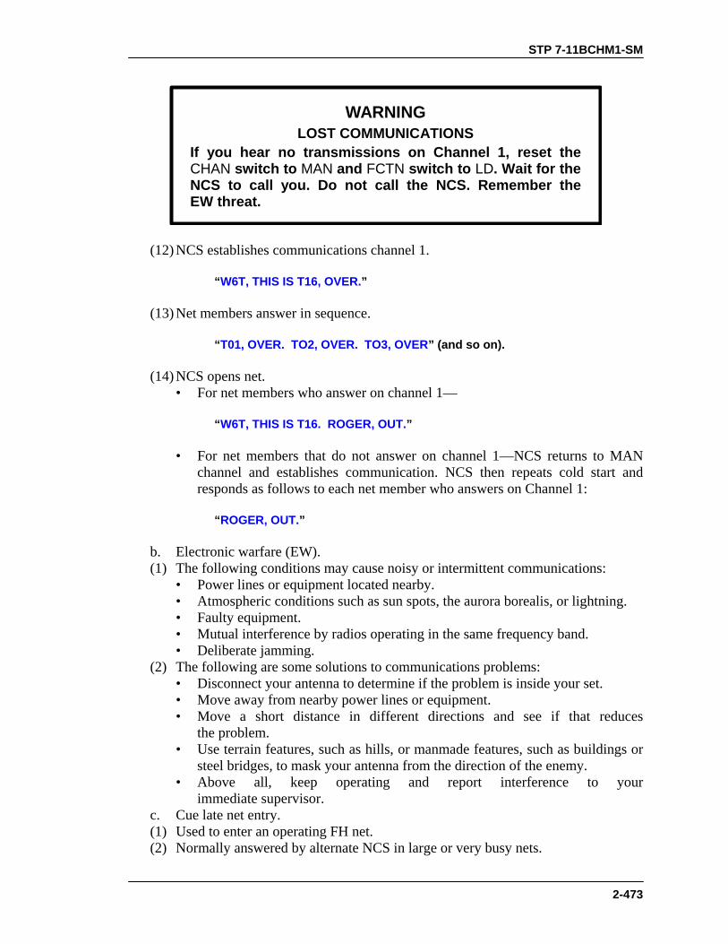
STP 7-11BCHM1-SM
2-473
WARNINGLOST COMMUNICATIONS
If you hear no transmissions on Channel 1, reset theCHAN switch to MAN and FCTN switch to LD. Wait for theNCS to call you. Do not call the NCS. Remember theEW threat.
(12) NCS establishes communications channel 1.
“W6T, THIS IS T16, OVER.”
(13) Net members answer in sequence.
“T01, OVER. TO2, OVER. TO3, OVER” (and so on). (14) NCS opens net. • For net members who answer on channel 1—
“W6T, THIS IS T16. ROGER, OUT.” • For net members that do not answer on channel 1—NCS returns to MAN
channel and establishes communication. NCS then repeats cold start and responds as follows to each net member who answers on Channel 1:
“ROGER, OUT.”
b. Electronic warfare (EW). (1) The following conditions may cause noisy or intermittent communications: • Power lines or equipment located nearby. • Atmospheric conditions such as sun spots, the aurora borealis, or lightning. • Faulty equipment. • Mutual interference by radios operating in the same frequency band. • Deliberate jamming. (2) The following are some solutions to communications problems: • Disconnect your antenna to determine if the problem is inside your set. • Move away from nearby power lines or equipment. • Move a short distance in different directions and see if that reduces
the problem. • Use terrain features, such as hills, or manmade features, such as buildings or
steel bridges, to mask your antenna from the direction of the enemy. • Above all, keep operating and report interference to your
immediate supervisor. c. Cue late net entry. (1) Used to enter an operating FH net. (2) Normally answered by alternate NCS in large or very busy nets.
STP 7-11BCHM1-SM
2-474
(3) Load cue frequency in cue channel. (a) Set CHAN to CUE. (b) Repeat procedures used for loading manual channel. (4) Set controls. Set FCTN to LD, RF to HI or PA, set CHAN to CUE. (5) Initiate cue call. (a) Turn KY-57 OFF and key the handset’s push-to-talk (PTT) switch for 4 to 6 seconds. (b) Turn the KY-57 ON and key the handset to clear the alarm. (c) When anyone is talking on the net, neither the NCS nor the alternate NCS (ALT) can receive your cue signal. So, if neither the NCS nor the alternate NCS (ALT) responds within 30 seconds of your cue call, turn the KY-57 OFF, key the handset PTT switch for 4 to 6 seconds, turn the KY-57 back ON, then key the handset again to clear the alarm. Finally, repeat the following procedures every 30 seconds until the NCS or ALT calls you:
NCS or ALT: “UNKNOWN STATION, THIS IS T16, OVER.” NET MBR: “T16 THIS IS T01, REPORTING INTO NET, OVER.” NCS or ALT: “T01 THIS IS T16. MEET ME ON MANUAL, OUT.”
NOTE: The net member cued the net because he needed a cold start. The NCS or
ALT does not need to issue any other instructions. The net member automatically sets his controls for a cold start.
(6) Net member sets CHAN to MAN and FCTN to LD. (7) NCS and net member conduct normal cold start net opening.
EVALUATION PREPARATION
Setup: At the test site, provide all equipment and materials listed in the task conditions statement. Brief Soldier: Tell the soldier to operate the radio as a member station in a radio net.

STP 7-11BCHM1-SM
2-475
EVALUATION GUIDE
Performance Measures
Results
1. Perform net member premission checks.
P F
2. Perform net member cold start net opening.
P F
3. Perform net member cue late net entry. P F
FEEDBACK If the soldier passes all steps, score him GO. If he fails any steps, score him NO-GO, then show him what he did wrong and how to do it correctly.
REFERENCES Required Related Unit SOI DA Pam 738-750 FM 24-18 FM 24-19 TM 11-5820-890-10-1 TM 11-5820-890-10-3

STP 7-11BCHM1-SM
2-476
USE THE KTC 1400(*) NUMERICAL CIPHER/ AUTHENTICATION SYSTEM
113-573-4006 CONDITIONS Given map coordinates to be encoded, encoded numerical information to be decoded, an authentication challenge for the reply, a pencil, and paper. Also given a unit SOI extract with KTC 1400(*) numeral cipher/authentication system and supplemental instructions. STANDARDS Use the KTC 1400(*) numeral cipher/authentication system to encode and decode, and provide a correct reply for a challenge to authenticate.
TRAINING AND EVALUATION See security precautions (Figure 1).
SECURITY PRECAUTIONS
1. Each code set of the KTC 1400(*) remains effective for 12 hours unless the signal officer directs otherwise. (Refer to unit SOI supplemental instructions, items 102, 113, 114, and 120.)
2. Encrypt no more than fifteen characters with a single SET INDICATOR. If you must encrypt an entire message, use the operation code KTC 1400(*).
3. Use only random letter combinations as SET INDICATORs.
4. Use the variant letters provided for each numeral impartially and randomly.
5. Each table has plaintext numbers and letters after the fifth, twelfth, and eighteenth lines (included to ease operation). DO NOT use these as cipher values.
6. In challenge and reply authentication, verify only the station. Do not accept a challenge as an authentication. To verify both stations, challenge them both, then wait for their reply. (Refer to unit SOI authentication instructions, item 115.)
7. Challenge again if you receive an incorrect reply, if the station requests a “standby,” or if you notice an unusual delay between your challenge and their reply.
8. Never give the challenge and reply in the same transmission (self-authentication).
Figure 1. Security precautions.
STP 7-11BCHM1-SM
2-477
EVALUATION GUIDE Performance Measures
Results
1. Find the line encryption. Reference the unit SOI, item 120. P F a. Randomly select any two letters (except “Z”) for SET INDICATOR (SI).
b. Look in the LINE INDICATOR column and find the first letter you selected.
c. Look in the LINE INDICATOR column and find the second letter you selected.
d. Look in the LINE INDICATOR column and find the SET LETTER. Use this line to encrypt up to 15 characters.
2. Encrypt the grid zone letters that were provided to you by the supervisor. Reference the unit SOI, item 120.
P F
NOTE: Include grid zone letters in messages only when the recipient will need them in order to understand the message. Do not encrypt any other letters. If needed to prevent a the student from misunderstanding, the trainer should say, “The message includes grid zone letters.”
3. Encrypt the numbers the supervisor provided to you. Reference the unit SOI, item 120.
P F
4. Prepare for transmission. Reference the unit SOI, item 120.
P F
5. Decrypt the grid zone letters and numbers. Reference the unit SOI, item 120.
P F
6. Issue a challenge and authenticate the reply. Reference the unit SOI, items 115 and 120.
P F
a. Challenge a station using authentication. b. Reply to a station using authentication.
7. Perform transmission authentication. Reference the unit SOI, items 116 and 120.
P F
FEEDBACK If the soldier passes all steps, score him GO. If he fails any steps, score him NO-GO, then show him what he did wrong and how to do it correctly.

STP 7-11BCHM1-SM
2-478
REFERENCES Required Related Unit SOI None KTC 1400(*)

STP 7-11BCHM1-SM
2-479
ENCODE AND DECODE MESSAGES USING KTC 600(*) TACTICAL OPERATIONS CODE
113-573-4003 CONDITIONS Given a tactical or nontactical situation, in an NBC environment or not; given a requirement to encode plaintext messages (provided) and to decode encoded messages (provided). Supervision, assistance, and a unit SOI extract with KTC 600(*) (OPCODE) will be available. STANDARDS Use the KTC 600(*) to encode and decode a message IAW the performance measures within 30 seconds per code group or word/phrase.
TRAINING AND EVALUATION See security precautions (Figure 1).
SECURITY PRECAUTIONS
1. Note that each set of the KTC 600(*) tactical operations code remains effective for 48 hours unless otherwise directed by the signal office. (Refer to the Unit SOI, KTC 600[*] operating instructions.)
2. Never mix plain language with encoded messages.
3. Keep spelling and punctuation to a minimum.
4. For the more commonly used phrases, use the variant code groups provided to you impartially and at random.
5. Spare groups provided to you let you assign additional variants to plaintext phrases in the code, or to assign new plaintext values, as required.
Figure 1. Security precautions.

STP 7-11BCHM1-SM
2-480
EVALUATION GUIDE Performance Measures
Results
1. Encode a message. (The supervisor will provide the message.) a. Write the plaintext message on a piece of paper. Leave enough space above each line to write the code values. b. Turn to the code set appropriate for that time period. c. Find the word, phrase, or number you must encode. Write the three-letter code group on the message.
P F
NOTES: 1. The encode section of the operations code consists of the words and phrases, arranged alphabetically, commonly used in tactical operations.
2. The numeral section of the code provides two types of code groups for each number:
• Use the numbers not followed by the symbol (+) when you use the numerals singularly or as the first final number of a group of numbers.
• Use the numbers with the (+) ending with all but the final number of a group of numbers.
2. Decode a message that has been provided. P F a. After receiving and writing down the encoded message, turn to the code set appropriate for that time period.
NOTE: The decode section of the operations code consists of the three-letter code groups in alphabetical order, with a word, phrase, or number to the right of each group.
b. Find the code group. Write the word, phrase, or number under that group in the encoded message.
NOTE: Some vocabulary entries include word endings such as -ing, -ed, -ly. If the message content does not clearly indicate which ending applies, spell out these endings.
FEEDBACK If the soldier passes all steps, score him GO. If he fails any steps, score him NO-GO, then show him what he did wrong and how to do it correctly.

STP 7-11BCHM1-SM
2-481
REFERENCES Required Related Unit SOI, KTC 600(*) None

STP 7-11BCHM1-SM
2-482
COMMUNICATIONS
OPERATE TELEPHONE SET TA-312/PT 113-600-2007
CONDITIONS Given a tactical or nontactical situation, in any weather conditions, and in an NBC environment or not, and given two telephone sets TA-312/PT (installed), an H-144/U headset, a screwdriver, and TM 11-5805-201-12. STANDARDS Initiate a call and complete it IAW the performance measures.
TRAINING AND EVALUATION
EVALUATION GUIDE
Performance Measures
Results
1. Initiate a call in the prescribed mode of operation.
P F
2. Answer calls in the prescribed mode of operation.
P F
NOTE: If the telephone operator must keep his hands free during operations, you may use Performance Measure 3.
3. Answer calls using external headset.
P F
NOTE: Operating under less than ideal conditions may require the operator to make special operating considerations.
4. Operate telephone set under unusual conditions. P F
FEEDBACK If the soldier passes all steps, score him GO. If he fails any steps, score him NO-GO, then show him what he did wrong and how to do it correctly.
REFERENCES Required Related TM 11-5805-201-12 None

STP 7-11BCHM1-SM
2-483
INSTALL HOT LOOP 113-588-1087
CONDITIONS Given a tactical or nontactical situation, in any weather conditions, an NBC environment or not, and a requirement to establish a hot loop. Also given one roll of either WD-1/TT OR WD-1A on a reel, four operational two-wire tactical field telephones, tool equipment TE-33, one reel unit RL-31E or CE-11 or, as required, four prepared tags, four stakes, and one hammer. STANDARDS Soldier installs a hot loop and completes a communications check within 20 minutes.
TRAINING AND EVALUATION Training Information Outline
1. Install a field wire loop. a. Lay out the field wire from position A to each position in turn, until you have connected all positions. Complete the loop by returning to position A (Figure 1).
POSITION C
POSITION B
POSITION A
POSITION D
HOT LOOP USINGWD-1 OR WD-1A
= TWO-WIRE TACTICAL FIELD TELEPHONE
Figure 1. Field wire layout.
b. Keep wire behind the individual positions. c. Tie the wire to a fixed object, or stake, near each position and leave enough slack in the wire for connections. 2. Connect each two-wire tactical telephone to the hot loop, position A. a. Connect the hot loop to the telephone. (1) Strip 1/2 inch of insulation off the two wires at each end of the hot loop.

STP 7-11BCHM1-SM
2-484
(2) Connect one of the wires from each end of the hot loop to one binding post of the telephone, and the other wire from each end of the loop to the other binding post (Figure 2).
BINDINGPOSTS
Figure 2. Connect the hot loop to the telephone.
b. Connect the other telephones to the hot loop. (1) Go to one of the positions in the hot loop. (2) Pick up the wire. (3) Cut the insulation on one conductor without cutting the wire strands. Use the TL-13-A pliers or TL-29 knife. (4) Grasp the insulation on each side of the cut and pull the insulation apart to expose 1/2 inch of wire strands on each conductor (Figure 3).
CONDUCTOR A
3 TO 6 INCHES
Figure 3. Wire strands on conductor.
(5) Repeat the steps in subparagraphs (1) and (2) on the other conductor. (6) Slide an exposed 1/2-inch section of one conductor into one binding post of the telephone. (7) Slide the exposed 1/2-inch section of the other conductor into the other binding post of the telephone.
STP 7-11BCHM1-SM
2-485
(8) Repeat the steps in subparagraphs (1) through (7) to connect each telephone in the hot loop. 3. Make a communications check. Use any telephone in the system and ring down the circuit. If all positions answer, you have installed the hot loop correctly. If any position does not answer, check the connections.
EVALUATION GUIDE
Performance Measures
Results
1. Install a field wire hot loop to four designated positions.
P F
2. Connect a two-wire tactical telephone set to the field wire hot loop at each designated position.
P F
FEEDBACK If the soldier passes all steps, score him GO. If he fails any steps, score him NO-GO, then show him what he did wrong and how to do it correctly.
REFERENCES Required Related None None

A-1
APPENDIX A
PROPONENT SCHOOL OR AGENCY CODES NOTE: The first three digits of the task number indicates the school or agency
responsible for the task content:
031 US Army Chemical School ATTN: ATZN-CM-FIFort McClellan, AL 36203-5020
051 US Army Engineer School ATTN: ATZA-TDI-CFort Belvoir, VA 22060-5291
113 US Army Signal Center ATTN: ATZH-TD-AFort Gordon, GA 30905-5070
081 US Army Medical Department Center ATTN: HSHA-TDPFort Sam Houston, TX 78234-6100

B-1
APPENDIX B
EXAMPLE COMPLETED DA FORM 5164-R (HANDS-ON EVALUATION)
See STP 21-24-SMCT or AR 350-57 for reproducible DA Form 5164-R and instructions for its use.

STP 7-11BCHM1-SM
B-2
HANDS-ON EVALUATIONFor use of this form, see AR 350-57; the proponent agency is DOCSOPS
DATE
TASK TITLEUnload an M16A1 or M16A2 Rifle
TASK NUMBER071-311-2028
SCORE(Check One)
ITEM
a
PERFORMANCE STEP TITLE
bPASS
CFAIL
D
1 Places the selector lever on SAFE P F
2 Removes the magazine P F
3 Locks the bolt open P F
4 Returns the charging handle forward P F
5 Checks the receiver and chamber P F
6 Allows the bolt to go forward P F
P F
P F
P F
P F
P F
P F
P F
P FEVALUATOR'S NAME UNIT
SOLDIER'S NAME STATUS GO NO GO
DA FORM 5164-R, SEP 85
XXX
XX
X
15 May 1999
XPFC MacDonoughSSG G omez
B-1. Example completed DA Form 5164-R, Hands-On Evaluation.

C-1
APPENDIX C
CRITICAL TASKS
This appendix lists all 11BCHM skill level 1 critical tasks. Some of these critical tasks are not published in this manual in training evaluation outlines. Each 11BCHM soldier is responsible for maintaining task proficiency on critical tasks. These are the tasks the soldier must know in order to properly perform the missions and functions of the MOS and duty position in support of the unit’s METL.
WEAPONS REFERENCES 071-317-0000 Prepare an Antiarmor Range Card FM 23-34
441-091-1102 Engage Hostile Aircraft with Small Arms FM 44-8
071-002-0001 Maintain a Caliber .45 Pistol FM 23-35
071-002-0002 Perform a Function Check on a Caliber .45 Pistol FM 23-35
071-002-0003 Correct Malfunctions of a Caliber .45 Pistol FM 23-35
071-002-0004 Load a Caliber .45 Pistol FM 23-35
071-002-0005 Unload a Caliber .45 Pistol FM 23-35
071-311-3002 Engage Targets with a Caliber .45 Pistol FM 23-35
071-004-0001 Maintain an M9 Pistol TM 9-1005-317-10
071-004-0002 Perform a Function Check on an M9 Pistol TM 9-1005-317-10
071-004-0003 Load an M9 Pistol FM 23-35 TM 9-1005-317-10
071-004-0004 Unload an M9 Pistol FM 23-35 TM 9-1005-317-10
071-004-0005 Correct Malfunctions of an M9 Pistol FM 23-35 TM 9-1005-317-10
071-004-0006 Engage Targets with an M9 Pistol FM 23-35 TM 9-1005-317-10
071-008-0001 Mount a Night Vision Sight AN/PVS-4 on an M16A1 or M16A2 Rifle FM 90-10-1 TM 11-5855-213-10
071-008-0002 Dismount a Night Vision Sight AN/PVS-4 from an M16A1 or M16A2 Rifle FM 5-34 TM 11-5855-213-10
071-311-2004 Zero an M16A1 Rifle FM 23-9
071-311-2006 Construct Field-Expedient Firing Aids for an M16A1 or M16A2 Rifle FM 7-8 FM 21-75
071-311-2007 Engage Targets with an M16A1 or M16A2 Rifle FM 23-9
071-311-2025 Maintain an M16A1 or M16A2 Rifle TM 9-1005-249-10
071-311-2026 Perform a Function Check on an M16A1 or M16A2 Rifle FM 23-9 TM 9-1005-249-10
071-311-2027 Load an M16A1 or M16A2 Rifle FM 23-9 TM 9-1005-319-10 TM 9-1005-249-10
071-311-2028 Unload an M16A1 or M16A2 Rifle FM 23-9 TM 9-1005-249-10

STP 7-11BCHM1-SM
C-2
WEAPONS REFERENCES 071-311-2029 Correct Malfunctions of an M16A1 or M16A2 Rifle FM 23-9 TM 9-1005-249-10
071-311-2030 Zero an M16A2 Rifle FM 23-9 TM 9-1005-249-10
071-315-2307 Zero a Night Vision Sight AN/PVS-4 to an M16A1 or M16A2 Rifle TM 11-5855-213-10
071-315-2308 Engage Targets with an M16A1 or M16A2 Rifle Using a Night Vision Sight AN/PVS-4
TM 11-5855-213-10
071-010-0001 Zero a Night Vision Sight AN/PVS-4 to an M249 Machine Gun FM 23-14
071-010-0002 Mount a Night Vision Sight AN/PVS-4 on an M249 Machine Gun FM 23-14
071-010-0003 Dismount a Night Vision Sight AN/PVS-4 from an M249 Machine Gun FM 23-14
071-010-0006 Engage Targets with an M249 Machine Gun FM 23-14
071-010-0007 Engage Targets with an M249 Machine Gun Using a Night Vision Sight AN/PVS-4 TM 11-5855-213-10
071-312-4004 Lay an M249 Machine Gun Using Field Expedients FM 23-14 TM 9-1005-201-10
071-312-4025 Maintain an M249 Machine Gun FM 23-14 TM 9-1005-201-10
071-312-4026 Perform a Function Check on an M249 Machine Gun FM 23-14 TM 9-1005-201-10
071-312-4027 Load an M249 Machine Gun FM 23-14
071-312-4028 Unload an M249 Machine Gun FM 23-14
071-312-4029 Correct Malfunctions of an M249 Machine Gun FM 23-14
071-312-4030 Zero an M249 Machine Gun FM 23-14 TM 9-1005-201-10
071-312-4032 Prepare a Range Card for an M249 Machine Gun FM 7-7J
071-020-0001 Mount a Night Vision Sight AN/PVS-4 on an M60 Machine Gun TM 11-5855-213-10
071-020-0002 Dismount a Night Vision Sight AN/PVS-4 from an M60 Machine Gun TM 11-5855-213-10
071-020-0006 Mount an M60 Machine Gun on an M122 Tripod FM 23-67
071-020-0007 Dismount an M60 Machine Gun from an M122 Tripod FM 23-67
071-312-3003 Lay an M60 Machine Gun Using Field Expedients FM 23-67
071-312-3004 Construct a Fighting Position for an M60 Machine Gun FM 7-7 FM 7-8 FM 23-67
071-312-3007 Prepare a Range Card for an M60 Machine Gun FM 23-67
071-312-3025 Maintain an M60 Machine Gun FM 23-67
071-312-3026 Perform a Function Check on an M60 Machine Gun FM 23-67
071-312-3027 Load an M60 Machine Gun FM 23-67
071-312-3028 Unload an M60 Machine Gun FM 23-67
071-312-3029 Correct Malfunctions of an M60 Machine Gun FM 23-67
071-312-3030 Zero an M60 Machine Gun FM 23-67
071-312-3031 Engage Targets with an M60 Machine Gun FM 23-67
071-315-0008 Engage Targets with an M60 Machine Gun Using a Night Vision Sight AN/PVS-4 FM 23-67 TM 11-5855-213-10

STP 7-11BCHM1-SM
C-3
WEAPONS REFERENCES 071-315-2313 Zero a Night Vision Sight AN/PVS-4 to an M60 Machine Gun TM 11-5855-213-10
071-022-0001 Maintain a Caliber .50 M2 Machine Gun FM 23-65
071-022-0010 Mount a Caliber .50 M2 Machine Gun on an M3 Tripod FM 23-65
071-022-0011 Dismount a Caliber .50 M2 Machine Gun from an M3 Tripod FM 23-65
071-022-0012 Mount a Caliber .50 M2 Machine Gun on a Vehicle TM 9-1005-213-10
071-022-0013 Dismount a Caliber .50 M2 Machine Gun from a Vehicle TM 9-1005-213-10
071-022-0014 Construct a Fighting Position for a Caliber .50 M2 Machine Gun FM 5-103
071-030-0001 Maintain a MK 19 Machine Gun FM 23-27 TM 9-1010-230-10
071-030-0007 Perform a Function Check on a MK 19 Machine Gun FM 23-27 TM 9-1010-230-10
071-030-0009 Mount a MK 19 Machine Gun on a Vehicle FM 23-27 TM 9-1010-230-10
071-030-0010 Dismount a MK 19 Machine Gun from a Vehicle FM 23-27 TM 9-1010-230-10
071-030-0011 Mount a MK 19 Machine Gun on an M3 Tripod FM 23-27 TM 9-1010-230-10
071-030-0012 Dismount a MK 19 Machine Gun from an M3 Tripod FM 23-27
071-030-0013 Construct a Fighting Position for a MK 19 Machine Gun FM 23-27
071-032-0001 Mount a Night Vision Sight AN/PVS-4 on an M203 Grenade Launcher TM 11-5855-213-10
071-032-0002 Dismount a Night Vision Sight AN/PVS-4 from an M203 Grenade Launcher TM 11-5855-213-10
071-032-0006 Construct Field-Expedient Firing Aids for an M203 Grenade Launcher FM 7-7 FM 7-7J FM 7-8
071-311-2103 Zero an M203 Grenade Launcher FM 23-31 TM 9-1010-221-10
071-311-2125 Maintain an M203 Grenade Launcher FM 23-31 TM 9-1010-221-10
071-311-2126 Perform a Function Check on an M203 Grenade Launcher FM 23-31 TM 9-1010-221-10
071-311-2127 Load an M203 Grenade Launcher FM 23-31 TM 9-1010-221-10
071-311-2128 Unload an M203 Grenade Launcher FM 23-31 TM 9-1010-221-10
071-311-2129 Correct Malfunctions of an M203 Grenade Launcher FM 23-31 TM 9-1010-221-10
071-311-2130 Engage Targets with an M203 Grenade Launcher FM 23-31 TM 9-1010-221-10
071-315-2351 Zero a Night Vision Sight AN/PVS-4 to an M203 Grenade Launcher TM 11-5855-213-10
071-315-2352 Engage Targets with an M203 Grenade Launcher Using a Night Vision Sight AN/PVS-4
TM 11-5855-213-10
071-034-0001 Load an M243 or M259 Smoke Grenade Launcher TM 9-2350-259-10
071-034-0002 Unload an M243 or M259 Smoke Grenade Launcher TM 9-2350-259-10
071-034-0003 Perform Misfire Procedures on an M243 or M259 Smoke Grenade Launcher TM 9-2350-259-10
071-034-0004 Fire an M243 or M259 Smoke Grenade Launcher TM 9-2350-259-10
071-034-0007 Maintain an M243 or M259 Smoke Grenade Launcher TM 9-2350-259-10
071-318-2202 Engage Targets with an M72A2/A3 Light Antitank Weapon FM 23-33

STP 7-11BCHM1-SM
C-4
WEAPONS REFERENCES 071-318-2203 Perform Misfire Procedures on an M72A2/A3 Light Antitank Weapon FM 23-33
071-318-2210 Prepare an M72A2/A3 Light Antitank Weapon for Firing FM 23-33
071-318-2211 Restore an M72A2/A3 Light Antitank Weapon to Carrying Configuration FM 23-33
071-052-0001 Maintain an M47 Medium Antitank Weapon TM 9-1425-484-10
071-052-0003 Construct a Fighting Position for an M47 Medium Antitank Weapon FM 7-8
071-052-0004 Restore an M47 Medium Antitank Weapon to Carrying Configuration TM 9-1425-484-10
071-052-0005 Operate a Night Vision Sight AN/TAS-5 TM 9-1425-484-10
071-052-0006 Engage Targets with an M47 Medium Antitank Weapon TM 9-1425-484-10
071-317-3302 Prepare an M47 Medium Antitank Weapon for Firing TM 9-1425-484-10
071-317-3306 Perform Misfire Procedures on an M47 Medium Antitank Weapon TM 9-1425-484-10
071-054-0001 Prepare an M136 Launcher for Firing TM 9-1340-886-12
071-054-0002 Restore an M136 Launcher to Carrying Configuration TM 9-1340-886-12
071-054-0003 Perform Misfire Procedures on an M136 Launcher TM 9-1340-886-12
071-054-0004 Engage Targets with an M136 Launcher TM 9-1340-886-12
071-070-0001 Maintain an M202A1 Multishot Rocket Launcher TM 3-1055-456-12
071-070-0002 Perform a Function Check on an M202A1 Multishot Rocket Launcher TM 3-1055-456-12
071-070-0003 Load an M202A1 Multishot Rocket Launcher TM 3-1055-456-12
071-070-0004 Unload an M202A1 Multishot Rocket Launcher TM 3-1055-456-12
071-070-0005 Perform Misfire Procedures on an M202A1 Multishot Rocket Launcher TM 3-1055-456-12
071-070-0006 Prepare an M202A1 Multishot Rocket Launcher for Firing TM 3-1055-456-12
071-070-0007 Restore an M202A1 Multishot Rocket Launcher to Carrying Configuration TM 3-1055-456-12
071-070-0008 Engage Targets with an M202A1 Multishot Rocket Launcher TM 3-1055-456-12
051-192-1003 Install the M16A1 Antipersonnel Mine FM 5-34 FM 20-32 TM 9-1345-203-12&P
051-192-1021 Locate Mines by Visual Means FM 20-32
051-192-1104 Remove the M16A1 Antipersonnel Mine FM 5-34 FM 20-32
051-192-1117 Install the M21 Antitank Mine FM 5-34 FM 20-32
051-192-1118 Remove the M21 Antitank Mine FM 5-34 FM 20-32
051-192-1135 Locate Mines by Probing FM 20-32
051-193-1025 Neutralize Mines FM 20-32
071-098-0001 Recover a Mechanical Ambush FM 21-75
071-098-0002 Install a Mechanical Ambush FM 21-75
071-325-4401 Perform Safety Checks on Hand Grenades FM 23-30

STP 7-11BCHM1-SM
C-5
WEAPONS REFERENCES 071-325-4407 Employ Hand Grenades FM 23-30 TM 9-1330-200-12
071-325-4425 Employ an M18A1 Claymore Mine FM 23-23
071-325-4426 Recover an M18A1 Claymore Mine FM 23-23
VEHICLE REFERENCES
071-200-0002 Tow a Tracked Vehicle FM 7-7
551-721-1342 Maintain the Cooling System on an M998-Series Vehicle TM 9-2320-280-10
551-721-1343 Maintain the Fuel System on an M998-Series Vehicle TM 9-2320-280-10
551-721-1344 Maintain the Transmission System on an M998-Series Vehicle TM 9-2320-280-10
551-721-1345 Start an M998-Series Vehicle Using Auxiliary Power TM 9-2320-280-10
551-721-1346 Drive an M998-Series Vehicle TM 9-2320-280-10
551-721-1347 Maintain the Air Cleaner System on an M998-Series Vehicle TM 9-2320-280-10
551-721-1348 Maintain the Steering System on an M998-Series Vehicle TM 9-2320-280-10
551-721-1349 Maintain the Engine on an M998-Series Vehicle TM 9-2320-280-10
551-721-1350 Maintain the Brake System on an M998-Series Vehicle TM 9-2320-280-10
551-721-1351 Maintain the Battery System on an M998-Series Vehicle TM 9-2320-280-10
071-212-0001 Maintain the Air Cleaner System on an M113-Series Vehicle TM 9-2300-257-10
071-212-0002 Maintain the Electrical System on an M113-Series Vehicle TM 9-2300-257-10
071-212-0003 Maintain the Brake System on an M113-Series Vehicle TM 9-2300-257-10
071-212-0004 Maintain the Cooling System on an M113-Series Vehicle TM 9-2300-257-10
071-212-0005 Maintain the Engine on an M113-Series Vehicle TM 9-2300-257-10
071-212-0006 Maintain the Fuel System on an M113-Series Vehicle TM 9-2300-257-10
071-212-0007 Maintain the Steering System on an M113-Series Vehicle TM 9-2300-257-10
071-212-0008 Maintain the Transmission System on an M113-Series Vehicle TM 9-2300-257-10
071-212-0009 Maintain the Personnel Heater on an M113-Series Vehicle TM 9-2300-257-10
071-212-0010 Maintain the Fire Suppression System on an M113-Series Vehicle TM 9-2300-257-10
071-212-0011 Maintain the Exhaust System on an M113-Series Vehicle TM 9-2300-257-10
071-212-0012 Maintain the Bilge System on an M113-Series Vehicle TM 9-2300-257-10
071-212-0013 Maintain the Hydraulic System on an M113-Series Vehicle TM 9-2300-257-10
071-212-0014 Maintain the Track and Suspension System on an M113-Series Vehicle TM 9-2300-257-10
071-212-0015 Maintain the Hull on an M113-Series Vehicle TM 9-2300-257-10
071-212-0016 Prepare an M113-Series Vehicle for Water Operation TM 9-2300-257-10
071-212-0017 Maintain the Gas Particulate System on an M113-Series Vehicle TM 9-2300-257-10

STP 7-11BCHM1-SM
C-6
VEHICLE REFERENCES
071-212-0018 Operate the Gas Particulate System on an M113-Series Vehicle TM 9-2300-257-10
071-212-0019 Operate the M19 Periscope on an M113-Series Vehicle TM 9-2300-257-10
071-212-0020 Start an M113-Series Vehicle Using Auxiliary Power TM 9-2300-257-10
071-212-0021 Drive an M113-Series Vehicle TM 9-2300-257-10
BASIC TACTICS
071-326-0501 Move as a Member of a Fire Team FM 7-7 FM 7-8 FM 7-7J FM 7-70
071-326-0502 Move Under Direct Fire FM 21-75
071-326-0503 Move Over, Through, or Around Obstacles (Except Minefields) FM 21-75
071-326-0510 React to Indirect Fire While Dismounted FM 21-75
071-326-0511 React to Flares FM 21-75
071-326-0512 Estimate Range FM 6-30
071-326-0513 Select Temporary Fighting Positions FM 21-75
071-326-5703 Construct an Individual Fighting Position FM 7-8
071-331-0852 Clear a Field of Fire FM 7-7 FM 7-8
071-410-0001 Perform Self-Extraction from a Minefield FM 20-32
MOVE
051-195-1004 Install Pickets, Make Barbed Wire Ties, and Install Concertina FM 5-34 STP 5-12B24-SM-TG
071-326-0541 Perform Movement Techniques During MOUT FM 90-10-1
071-326-0542 Enter a Building During MOUT FM 90-10-1
071-326-0550 Prepare Positions for Individual and Crew-Served Weapons During MOUT FM 90-10 FM 90-10-1
071-326-0557 Select Hasty Firing Positions During MOUT —
NAVIGATE
071-329-1005 Determine a Location on the Ground by Terrain Association FM 21-26
071-329-1006 Navigate from One Point on the Ground to Another Point While Dismounted FM 21-26
071-329-1018 Determine Direction Without a Compass FM 21-26
071-329-1000 Identify Topographic Symbols on a Military Map FM 21-26
071-329-1001 Identify Terrain Features on a Map FM 21-26
071-329-1002 Determine the Grid Coordinates of a Point on a Military Map FM 21-26
071-329-1008 Measure Distance on a Map FM 21-26
071-329-1009 Convert Azimuths FM 21-26
071-329-1012 Orient a Map to the Ground by Map-Terrain Association FM 21-26

STP 7-11BCHM1-SM
C-7
NAVIGATE
071-510-0002 Compute Back Azimuths FM 21-26
071-329-1003 Determine a Magnetic Azimuth Using a Lensatic Compass FM 21-26
071-329-1011 Orient a Map Using a Lensatic Compass FM 21-26
SUSTAIN
051-191-1501 Perform Individual Camouflage FM 5-20 FM 21-75
051-191-1362 Camouflage Equipment FM 5-20 FM 21-75
071-600-0001 Destroy Supplies and Equipment FM 5-25
081-831-1000 Evaluate a Casualty FM 21-11
081-831-1003 Clear an Object from the Throat of a Conscious Casualty FM 21-11
081-831-1005 Prevent Shock FM 21-11
081-831-1007 Give First Aid for Burns FM 21-11
081-831-1008 Give First Aid for Heat Injuries FM 21-11
081-831-1009 Give First Aid for Frostbite FM 21-11
081-831-1016 Put on a Field or Pressure Dressing FM 21-11
081-831-1017 Put on a Tourniquet FM 21-11
081-831-1025 Apply a Dressing to an Open Abdominal Wound FM 21-11
081-831-1026 Apply a Dressing to an Open Chest Wound FM 21-11
081-831-1030 Administer Nerve Agent Antidote to Self (Self-Aid) FM 21-11
081-831-1031 Administer First Aid to a Nerve Agent Casualty (Buddy-Aid) FM 21-11
081-831-1033 Apply a Dressing to an Open Head Wound FM 21-11
081-831-1034 Splint a Suspected Fracture FM 21-11
081-831-1040 Transport a Casualty Using a One-Man Carry FM 21-11
081-831-1041 Transport a Casualty Using a Two-Man Carry or an Improvised Litter FM 21-11
081-831-1042 Perform Mouth-to-Mouth Resuscitation FM 21-11
081-831-1043 Practice Preventive Medicine FM 21-11
181-906-1505 Conduct Combat Operations According to the Law of War FM 27-2 FM 27-10
191-377-5250 Handle Enemy Personnel and Equipment FM 27-10-2
031-503-1004 Protect Yourself from Chemical and Biological Injury/Contamination Using Your M17-Series Protective Mask with Hood
TM 3-4240-279-10
031-503-1005 Maintain Your M17-Series Protective Mask with Hood TM 3-4240-279-10
031-503-1006 Protect Yourself from NBC Injury/Contamination When Drinking from Your Canteen While Wearing Your Protective Mask
TM 3-4240-279-10 TM 3-4240-280-10
TM 3-4240-300-10-1
031-503-1007 Decontaminate Your Skin and Personal Equipment Using an M258A1 Decontamination Kit
FM 3-5

STP 7-11BCHM1-SM
C-8
SUSTAIN
031-503-1008 Protect Yourself from Chemical and Biological Injury/Contamination While Eliminating Body Waste When Wearing MOPP4
FM 3-4 FM 21-11
031-503-1011 Maintain Your M24- or M25-Series Protective Mask with Hood TM 3-4240-280-10
031-503-1012 Protect Yourself from Chemical and Biological Injury/Contamination Using Your M24- or M25-Series Protective Mask with Hood
TM 3-4240-280-10
031-503-1014 Identify Chemical Agents Using M8 Detector Paper TM 3-6665-307-10
031-503-1015 Protect Yourself from NBC Injury/Contamination with Mission-Oriented Protective Posture (MOPP) Gear
FM 3-4
031-503-1018 React to a Nuclear Hazard FM 3-3 FM 3-4 FM 3-100
031-503-1019 React to Chemical or Biological Hazard/Attack FM 3-4 FM 21-60
031-503-1020 Detect Chemical Agents Using M9 Detector Paper TM 3-6665-311-10
031-503-1023 Protect Yourself from NBC Injury/Contamination When Changing Mission-Oriented Protective Posture (MOPP) Gear
FM 3-5
031-503-1024 Replace Canister on Your M40-Series Protective Mask TM 3-4240-300-10-1 TM 3-4240-300-10-2
031-503-1025 Protect Yourself from Chemical and Biological Injury/Contamination Using Your M40-Series Protective Mask with Hood
TM 3-4240-300-10-1
031-503-1026 Maintain Your M40-Series Protective Mask with Hood TM 3-4240-300-10-1
031-503-1028 Protect Yourself from Chemical and Biological Injury/Contamination Using Your M42 Protective Mask with Hood
TM 3-4240-300-10-2
031-503-1029 Maintain Your M42 Protective Mask with Hood TM 3-4240-300-10-2
031-503-1030 Prepare the Chemical Agent Monitor for Operation TM 3-4230-216-10 TM 3-4230-278-10
TM 3-6665-327-13&P
031-503-1031 Put the Chemical Agent Monitor into Operation TC 3-3-5 TM 3-6665-327-13&P
031-503-1032 Prepare the Chemical Agent Monitor for Movement or Storage FM 3-5 TC 3-3-5 TM 3-6665-327-13&P
031-503-1033 Decontaminate Your Skin Using the M291 Skin Decontaminating Kit (SDK) —
031-503-1034 Decontaminate Your Individual Equipment Using the M295 Individual Equipment Decontamination Kit (IEDK)
—
031-506-1052 Protect Yourself and Others from Chemical and Biological Injury/Contamination by Using (Entering or Exiting) a Collective Protection Shelter
—
031-507-1002 Decontaminate Equipment Using ABC M11 Decontaminating Apparatus STP 3-54B1 TM 3-4230-204-12&P
031-507-1021 Mark NBC Contaminated Area FM 3-5
031-507-1022 Decontaminate Equipment Using M13 Decontaminating Apparatus, Portable FM 3-5 STP 3-54B1
031-507-2006 Conduct Hasty Decontamination STP 3-54B1
RECONNAISSANCE AND SECURITY
071-315-0003 Operate a Night Vision Sight AN/PVS-4 TM 11-5855-213-10
071-315-0030 Operate Night Vision Goggles AN/PVS-5 TM 11-5855-238-10
071-315-0031 Maintain Night Vision Goggles AN/PVS-5 TM 11-5855-238-10

STP 7-11BCHM1-SM
C-9
RECONNAISSANCE AND SECURITY
071-315-0090 Maintain a Thermal Viewer AN/PAS-7 TM 11-5855-246-10
071-315-0091 Operate a Thermal Viewer AN/PAS-7 TM 11-5855-246-10
071-710-0001 Maintain a Night Vision Sight AN/PVS-4 TM 11-5855-213-10
071-710-0008 Operate Night Vision Goggles AN/PVS-7 TM 11-5855-246-10
071-710-0009 Maintain Night Vision Goggles AN/PVS-7 TM 11-5855-246-10
071-331-0001 Perform as a Member of a Patrol FM 21-75
071-331-0801 Challenge Persons Entering Your Area FM 21-75 FM 22-6
071-331-0804 Perform Surveillance Without the Aid of Electronic Devices FM 21-75
071-331-0808 Identify Threat Weapons FM 7-8 FM 71-1
071-331-0815 Practice Noise, Light, and Litter Discipline FM 21-75
071-730-0001 Emplace Pyrotechnic Early Warning Devices FM 5-25 FM 5-34
071-730-0002 Recover Pyrotechnic Early Warning Devices FM 5-25 FM 5-34
071-730-0008 Employ Field-Expedient Early Warning Devices FM 5-25 FM 5-34
301-348-1050 Report Information of Potential Intelligence Value —
878-920-1002 Recognize Friendly and Threat Armored Vehicles and Aircraft FM 1-402 FM 44-30
COMMUNICATE
071-810-0003 Construct a Field-Expedient Antenna FM 24-1
071-810-0004 Maintain Intercommunications Set AN/VIC-1 on a Tracked Vehicle (Includes FM Radio)
TM 11-5820-401-10-2
113-571-1004 Operate in Radio Nets FM 24-18
113-573-4003 Encode and Decode Messages Unit SOI, Using KTC 600(*) Tactical KTC 600(*) Operations Code
—
113-573-4006 Use the KTC 1400(*) Numerical Unit SOI, Cipher/Authentication System KTC 1400(*)
—
113-573-6001 Recognize Electronic Countermeasures (ECM) and Implement Electronic Counter Countermeasures (ECCM)
FM 24-18
113-573-7017 Prepare/Submit Operator's (MIJI) Report FM 24-18
113-587-1064 Prepare SINCGARS (Manpack) for Operation FM 24-18
113-587-2059 Operate Radio Set AN/PRC-77 with TSEC/KY-57 TM 11-5820-498-12
113-587-2061 Operate Radio Set AN/VRC-64 or AN/GRC-160 with TSEC/KY-57 TM 11-5820-498-12
113-587-2064 Operate Radio Set AN/VRC-12 Series with TSEC/KY-57 TM 11-5820-401-10-2
113-587-2070 Operate Secure SINCGARS Single Channel (SC) FM 24-18
113-587-2071 Operate Secure SINCGARS Frequency Hopping (FH) (Net Members) FM 24-18
113-587-2072 Operate Secure SINCGARS Frequency Hopping (FH) Net Control Station (NCS) FM 24-18

STP 7-11BCHM1-SM
C-10
COMMUNICATE
113-587-2075 Operate Secure SINCGARS Data Operations FM 24-18
113-587-2076 Operate Secure SINCGARS Using Control Monitor (CM) FM 24-18
113-587-2077 Operate SINCGARS Remote Control Unit (RCU) FM 24-18
113-622-2011 Operate Intercommunications Set AN/VIC-1 on a Tracked Vehicle (Includes FM Radio)
TM 11-5820-401-10-2
071-820-0001 Operate Telephone Set TA-1/PT TM 11-5805-201-12
071-820-0002 Install Telephone Set TA-1/PT TM 11-5805-201-12
071-820-0003 Install Communications Wire Lines FM 24-20
071-820-0004 Recover Communications Wire Lines FM 24-20
113-571-1022 Perform Voice Communications —
113-572-4008 Transmit a Voice United States Message Text Format (USMTF) Message —
113-572-5005 Receive a Voice United States Message Text Format (USMTF) Message —
113-572-6006 Read a United States Message Text Format (USMTF) Message —
113-573-8006 Use an Automated Signal Operation Instruction (SOI) FM 24-35
113-588-1087 Install Hot Loop SH 7-180
113-588-4025 Repair Telephone Cable WD-1()/TT or WF-16/U FM 24-20
113-594-2005 Install and Operate Switchboard, Telephone, Manual SB-993/GT TM 11-5805-02-94-15
113-594-2014 Operate Switchboard, Telephone, Manual SB-22/PT TM 11-5805-202-12
113-600-1023 Install Tactical Telephones TM 11-5805-201-12
113-600-2007 Operate Telephone Set TA-312/PT TM 11-5805-201-12
113-600-3015 Perform Operator's PMCS on Tactical Telephone Sets TM 11-5805-201-12
071-326-0600 Use Visual Signaling Techniques While Dismounted FM 21-60
COMMAND AND STAFF
101-515-1900 Perform Mortuary Affairs Operations —

Glossary-1
GLOSSARY
ACRONYMS AND ABBREVIATIONS AC alternate current ACCP Army Correspondence Course Program AGS a 30-mm automatic grenade launcher developed by the former
Soviet Union AIT Advanced Individual Training AKM a 7.62-mm assault rifle developed by the former Soviet Union AKMS a 7.62-mm assault rifle developed by the former Soviet Union alt alternate ammo ammunition APC armored personnel carrier AR Army Regulation ARNG Army National Guard ARTEP Army Training and Evaluation Program AT antitank ATGM antitank guided missile batt battery BML by-product materials license BNCOC Basic NCO Course BMD a vehicle developed by the former Soviet Union BMP a fighting vehicle developed by the former Soviet Union BRDM a scout car developed by the former Soviet Union BT basic training C Centigrade CB chemical, biological CGy centigray; a unit of absorbed dose of radiation equal to a rad cGyph centigray per hour CLP cleaner, lubricant, preservative cm centimeter COMSEC communications security CP command post CRT cathode ray tube CSS combat service support CTA common table of allowances CTT common task test CX coaxial cable designator DA Department of the Army DAP decontaminating apparatus, portable DS direct support DS2 decontamination solution No. 2

STP 7-11BCHM1-SM
Glossary-2
DTG date-time group ECM electronic countermeasures ECCM electronic counter-countermeasures EENT end of evening nautical twilight EOD explosive ordnance disposal EPW enemy prisoner of war ERF electronic remote fill (offset frequency) EW electronic warfare F Fahrenheit FDC fire direction center FH frequency hopping FM field manual FO forward observer FOV field of view FPF final protective fires FPL final protective line FRAGO fragmentary order freq frequency ft feet gnd ground GSR ground surveillance radar HAW heavy antitank weapon HE high explosive HMMWV high mobility multipurpose wheeled vehicle IAW in accordance with ICOM intercommunications ID identification IEDK individual equipment decontamination kit IET initial entry training IL Illinois in inch IR infrared ITEP Individual Training and Evaluation Program ITP individual training plan JB job book km kilometer(s) LAW light antitank weapon; lubricant, arctic weather LBE load-bearing equipment

STP 7-11BCHM1-SM
Glossary-3
LD lighted display LSA logistics support analysis LZ landing zone m meter MAW medium antitank weapon MEDEVAC medical evacuation METL mission-essential task list METT-T mission, enemy, terrain, troops, and time available MG machine gun MIJI meaconing, intrusion, jamming, and interference mm millimeter MOPP mission-oriented protective posture MOS military occupational specialty MOSC military occupational specialty code MOUT military operations on urbanized terrain MRL multiple rocket launcher MPRJ Military Personnel Records Jacket, US Army MRL multiple rocket launchers MTP mission training plan NATO North Atlantic Treaty Organization NBC nuclear, biological, and chemical NCO noncommissioned officer NCOIC noncommissioned officer in charge NCS net control station NSN national stock number OEG operational exposure guidance OIC officer in charge OP observation point OPCODE operations code OPLAN operation plan OPORD operations order OPSEC operations security ORP objective rally point OSUT one-station unit training PDF principal direction of fire PEWS platoon early warning system PIR priority intelligence requirements PKM a general-purpose machine gun developed by the former Soviet
Union; the PKM uses a 7.62-mm x 54R (rimmed) cartridge (same as the SVD sniper rifle)
PL phase line PLDC Primary Leadership Development Course

STP 7-11BCHM1-SM
Glossary-4
PMCS preventive maintenance checks and services psi pounds per square inch PSYOP psychological operations PTT push-to-talk RATELO radiotelephone operator RBC rifle bore cleaner RCU remote control unit RDF radio direction finding RF radio frequency RPG a rocket-propelled grenade launcher developed by the former
Soviet Union; includes the RPG-7 and RPG-16, which are reloadable, and the RPG-18, which is disposable, and which is the oldest of the LAW-type RPGs
RPK a 7.62-mm light machine gun (the RPK) developed by the former Soviet Union
RPK-74 a 5.45 light machine gun developed by the former Soviet Union RPO radiation protection officer RT receiver/transmitter SAW squad automatic weapon SC single channel SI set indicator SINCGARS single-channel ground and airborne radio subsystem SL skill level SM soldier's manual SMCT soldier's manual of common tasks SOI signal operation instructions SOP standing operating procedures SPG-9 a 73-mm antitank recoilless gun developed by the former Soviet
Union STP soldier training publication SVD sniper rifle dragunou; a 7.62-mm x 54R (rimmed) cartridge sniper
rifle developed by the former Soviet Union T&E traversing and elevating TC training circular TEK traffic encryption key TG trainer's guide TM technical manual TMDE test measurement diagnostic equipment TO&E table of organization and equipment TOW tube-launched, optically tracked, wire-guided TP training practice; tank platoon TRP target reference point TSEC telecommunications security

STP 7-11BCHM1-SM
Glossary-5
TW target width US United States USAIS United States Army Infantry School USAR United States Army Reserve W wire
DEFINITIONS beaten zone The pattern formed when rounds or bursts strike the ground or a
target centigray A unit of absorbed dose of radiation equal to a rad defile A narrow passage in which troops can march only in a single file encoded (A message) converted into code manpack Designed to be carried by one person plaintext The intelligible form of an encrypted text or of its elements trip wire A low-placed concealed wire used to trip an enemy or trespasser
and to trigger an alarm or explosive device zulu time Greenwich mean time

References-1
REFERENCES
DOCUMENTS NEEDED
These documents must be available to the intended users of this publication. DA Form 2404 Equipment Inspection and Maintenance Worksheet, 1 April 79. DA Form 5517-R Standard Range Cards, February 86. FM 23-14 M249 Light Machine Gun in the Automatic Rifle Role, 6 January 94. FM 23-34 TOW Weapon System, 17 August 94. FM 23-27 MK 19, 40-mm Grenade Machine Gun, MOD 3, 27 December 88. FM 23-65 Browning Machine Gun, Caliber .50 HB, M2, 19 June 91. FM 23-67 Machine Gun, 7.62-mm, M60, 29 February 84; with Change 1,
17 March 87. FM 71-1 Tank and Mechanized Infantry Company Team, 26 January 98. FM 90-10 (HTF) Military Operations on Urbanized Terrain (MOUT) (How to Fight),
15 August 79. FM 90-10-1 An Infantryman's Guide to Combat in Built-Up Areas, 12 May 93;
with Change 1, 3 October 95. GTA 17-2-11 Combat Vehicle Identification (CVI) Training Cards, 1984. GTA 17-2-13 Armored Vehicle Recognition, 1987. TM 9-1005-201-10 Operator's Manual for Machine Gun, 5.56-mm, M249 W/Equipment,
26 July 91; with Change 1, 25 November 96. TM 9-1005-213-10 Operator's Manual for Machine Guns, Caliber .50 Browning, M2,
Heavy Barrel Flexible, 6 August 92; with Change 1, 1 August 95 and Change 2, 6 August 96.
TM 9-1005-317-10 Operator's Manual for Pistol, Semiautomatic, 9MM, M9, 31 July 85;
with Change 1, 10 July 98; Change 2, 28 March 89; and Change 3, 14 December 90.
TM 11-5805-201-12 Operator's and Unit Maintenance Manual for Telephone Sets,
TA-312/PT and TA-312A/PT, 1 August 90.
STP 7-11BCHM1-SM
References-2
READINGS RECOMMENDED
These readings contain relevant supplemental information. DA Pam 738-750 Functional Users Manual for the Army Maintenance Management
System, 1 August 94. FM 3-3 Chemical and Biological Contamination Avoidance,
16 November 1992; with Change 1, 29 September 94. FM 3-5 NBC Decontamination, 17 November 93. FM 5-34 Engineer Field Data, 30 August 99. FM 5-101 Mobility, 23 January 85. FM 5-250 Explosives and Demolitions, 30 July 98; with Change 1, 30 June 99. FM 7-7 The Mechanized Infantry Platoon and Squad (APC), 15 March 85. FM 7-7J Mechanized Infantry Platoon and Squad (Bradley), 7 May 93. FM 7-8 Infantry Rifle Platoon and Squad, 22 April 92. FM 20-32 Mine/Countermine Operations, 29 May 98; with Change 1,
30 June 99. FM 21-10 Field Hygiene and Sanitation, 22 November 88. FM 21-11 First Aid for Soldiers, 27 October 88; with Change 1, 28 August 89
and Change 2, 4 December 91. FM 21-75 Combat Skills of the Soldier, 3 August 84. FM 23-25 Light Antiarmor Weapons, 17 August 94. FM 23-31 40-mm Grenade Launcher, M203, 20 September 94. FM 23-35 Combat Training with Pistols and Revolvers, 3 October 88. FM 24-18 Tactical Single-Channel Radio Communications Techniques,
30 September 87. FM 31-70 Basic Cold Weather Manual, 12 April 68; with Change 1,
17 December 68. STP 21-1-SMCT Soldier's Manual of Common Tasks Skill Level 1, 1 October 94.

STP 7-11BCHM1-SM
References-3
TM 3-4230-214-12&P Operator's and Unit Maintenance Manual Including Repair Parts and Special Tools List for Decontaminating Apparatus: Portable, 14 Liter, M13 and Decontaminating Apparatus: Portable, 14 Liter, M13 (Practice), 15 August 92.
TM 3-9905-001-10 Operator's Manual for Marking Set, Contamination: Nuclear,
Biological, Chemical (NBC), 23 August 82; with Change 1, 31 August 87.
TM 9-1010-221-10 Operator's Manual for 40-mm Grenade Launcher, M203,
17 December 84; with Changes 1-6, dated 22 April 85 through 17 August 98.
TM 9-1010-230-10 Operator's Manual for Machine Gun, 40-mm, MK 19, MOD 3, 28
November 96. TM 9-1010-231-13&P Operator's, Organizational and Intermediate Maintenance with
Repair Parts List and Components List [for] Mount, Machine Gun, MK 64: MOD 4; MOD 5; MOD 6; MOD 7; MOD 8 Used With Machine Gun, MK 19; MOD 3 Used With 40-mm Machine Gun, M2 Caliber .50 Machine Gun, M60 7.62-mm Machine Gun, M60E3 7.62-mm, 31 January 89.
TM 9-1315-886-12 Operator's and Unit Maintenance Manual for Launcher and
Cartridge, 84 Millimeter: M136 (AT4), 15 May 90; with Change 1, 31 December 90; Change 2, 15 June 92; and Change 3, 30 May 95.
TM 9-1425-480-24P Organizational, Direct Support, and General Support Maintenance
Repair Parts and Special Tools Lists (Including Depot Maintenance Repair Parts and Special Tools) for Tracker, Infrared, Guided Missile, SU-36P and Carrying Bag; Night Vision Sight-Tracker, Infrared, AN/TAS-5; Case, Guided Missile Infrared Tracker, M213; Kit, APC Installation Dragon Hardware and Mount, Guided Missile Launcher, M175 (Dragon Medium Antitank/Assault Weapon System), 14 August 91.
TM 9-1425-484-10 Operator's Manual for Dragon Weapon Guided Missile System,
Surface Attack: M47 (Medium Antitank/Assault Weapon System), 31 July 79; with Changes 1-13, dated 17 October 80 through 30 March 93.
TM 11-5820-890-10-1 Operator's Manual for SINCGARS Ground Combat Net Radio,
ICOM, 1 September 92. TM 11-5820-890-10-3 Operator's Manual for SINCGARS Ground Combat Net Radio,
Non-ICOM, 1 September 92. TM 11-5820-890-10-8 Operator's Manual, SINCGARS Ground Combat Net Radio, ICOM,
[ANCD and PLGR] 28 Feb 95.
STP 7-11BCHM1-SM
References-4
TM 11-5855-213-10 Operator's Manual for Night Vision Sight, Individual Served
Weapon, AN/PVS-4, 1 February 93; with Change 1, 15 June 93. TM 11-5855-238-10 Operator's Manual for Night Vision Goggles Ground Use:
AN/PVS-5 and AN/PVS-5A, AN/PVS-5B, AN/PVS-5C, Aviation Use: GM-6(V)1 Goggles GM-6(V)2 Goggles, 15 May 93.
TM 11-5855-246-10 Operator's Manual for Viewer, Infrared AN/PAS-7, 8 November 76;
with Change 1, 19 June 78; Change 2, 27 August 79; and Change 3, 26 May 81.
TM 11-5855-262-10-2 Operator's Manual for Night Vision Goggles, AN/PVS-7B,
1 December 97; with Change 1, 1 June 98.
INTERNET You may be able to view, save, or print some manuals from the Internet. Make sure to download only approved documents from official Army web sites such as the following: http://www.usapa.army.mil U.S. Army Publishing Agency From this site, you may view or download FM 200-1, and you may
be able to obtain other electronic administrative departmental publications and forms, to include Army Regulations; Department of the Army circulars, forms, and pamphlets; optional forms; standard forms; and Department of Defense forms:
http://www.adtdl.army.mil Army Doctrinal Literature Digital Library From this site, you may view or download FM 5-250, and you may
be able to obtain other Army Doctrinal and Training Publications (except engineering & medical), to include field manuals, professional bulletins, training circulars, and soldier training publications:
http://www.logsa.army.mil/ USAMC Logistics Support Activity From this site, you may view or download TM 9-1425-450-12 and
TM 9-2350-259-10.