infinity rate meter / totalizer clock • batch controllerinf7 infinity® rate meter / totalizer...
TRANSCRIPT

INF7
INFINITY® Rate Meter / TotalizerClock • Batch Controller
Operator’s Manual
® NEWPORT Electronics,Inc.
Made in the USA
®
SERIES

CountersFrequency MetersPID ControllersClock/Timers
PrintersProcess Meters
On/OffControllersRecordersRelative
HumidityTransmitters
ThermocouplesThermistors
Wire
Rate MetersTimers
TotalizersStrain Gauge
MetersVoltmeters
MultimetersSoldering Iron
TesterspH pens
pH ControllerspH Electrodes
RTDsThermowellsFlow Sensors
For Immediate AssistanceIn the U.S.A. and Canada: 1-800-NEWPORT®
In Mexico: (95) 800-NEWPORTSM
Or call your local NEWPORT Office.
Internet [email protected]
Additional products from
NEWPORTnetSM On-Line Servicehttp://www.newportUS.com
This device is marked with the international caution symbol. It is important to read the Setup Guide beforeinstalling or commissioning this device as it contains important information relating to safety and EMC.
® NEWPORT Electronics,Inc.
It is the policy of NEWPORT to comply with all worldwide safety and EMC/EMI regulations that apply.NEWPORT is constantly pursuing certification of its products to the European New ApproachDirectives. NEWPORT will add the CE mark to every appropriate device upon certification.The information contained in this document is believed to be correct but NEWPORT Electronics, Inc. accepts no liability for anyerrors it contains, and reserves the right to alter specifications without notice.
WARNING: These products are not designed for use in, and should not be used for, patient connected applications.PATENT NOTICE: The “Meter Case Bezel Design” is a trademark of NEWPORT Electronics, Inc., registered in the U.S. This product is covered by one or more of the following patents: U.S. No. D336,895; 5,274,577/ FRANCE BREVET No. 91 12756/UK PATENT No. 2,248,954; 2,249,837/ SPAIN 2,039,150; 9,102,259/ ITALY 1,249,456; 1,250,938/ CANADA 2,052,600/ GERMANY DE4134398C2. OTHER INTERNATIONAL PATENTS PENDING.

i
Table ofContents
Table of Contents -HOW TO USE THIS MANUAL
This manual is organized to follow a sequence of setting up themeter, configuring it, and operating it. The table of contentsreflects this sequence. The contents also show that the manualcontains a lot of information; we have taken care to answer likelyquestions and provide all the information you may need. We havepurposely included all sections in the contents, to allow you to useit as an index–to easily pinpoint specific information and godirectly to it.
SAFETY CONSIDERATIONS .......................................................................vi
SECTION 1 INTRODUCTION1.1 Description ...................................................................................11.2 Features .........................................................................................11.3 Meter Modes.................................................................................21.3.1 Rate Meter/Totalizer.....................................................................21.3.2 Rate Meter/Totalizer/Square Root Extractor ...............................21.3.3 Batch Controller...........................................................................21.3.4 Clock.............................................................................................21.4 Optional Boards Overview...........................................................31.4.1 Isolated Pulse Input Board............................................................31.4.2 Isolated Analog Input Board ........................................................31.4.3 Isolated Analog Output Board .....................................................41.4.4 Isolated Parallel BCD Output Board............................................41.4.5 Dual Relay Output and 4 Relay Output Board............................41.4.6 Isolated RS-232 Serial Communications Board ..........................41.4.7 Isolated RS-485 Serial Communications Board .........................51.5 Available Models and Options.....................................................5
SECTION 2 SETUP2.1 Unpacking ....................................................................................82.2 Safety Precautions ........................................................................102.2.1 Power Voltage ...............................................................................102.2.2 Power Wiring................................................................................112.3 Assembly/Disassembly ..................................................................11
Page

2.3.1 Opening the Meter.......................................................................112.3.2 Checking and Installing Jumpers .................................................152.3.2.1 Main Board Jumpers .....................................................................162.3.2.2 Optional Input and Output Board Jumper Information .............182.3.3 Installing Optional Boards ...........................................................192.3.3.1 Isolated Pulse Input Board............................................................212.3.3.2 Isolated Analog Input Board ........................................................222.3.3.3 Isolated Analog Output Board .....................................................232.3.3.4 Isolated Parallel BCD (Binary-Coded Decimal) Output Board ..242.3.3.5 Dual Relay and 4 Relay Output Board ........................................252.3.3.6 Isolated RS-232 Serial Communications Board ..........................252.3.3.7 Isolated RS-485 Serial Communications Board ..........................262.3.4 Reinserting the Main Board Assembly into the Case .................262.3.5 Wiring ...........................................................................................262.3.5.1 P1 - AC Power Wiring .................................................................272.3.5.2 Battery Backup Connections........................................................272.3.5.3 P2 - Control Input/Output Wiring ..............................................282.3.5.4 Basic Meter Input Wiring.............................................................292.3.5.5 Isolated Pulse Input Board Wiring ...............................................292.3.5.6 Isolated Analog Input Board Wiring ...........................................292.3.5.7 Isolated Analog Output Board Wiring.........................................292.3.5.8 Isolated Parallel BCD Output Board Wiring ...............................292.3.5.9 Dual Relay and 4 Relay Output Board Wiring ............................302.3.5.10 Isolated RS-232 or RS-485 Serial Comm. Board Wiring............302.4 Panel-Mount Assembly ................................................................30
SECTION 3 FRONT AND REAR FEATURES3.1 Front-Panel Displays and Buttons................................................333.2 Rear Connectors...........................................................................35
SECTION 4 BASIC CONCEPTS AND APPROACHES TO SETUP AND CONFIGURATION
4.1 Choosing an Operating Mode......................................................394.2 Mode-Associated Measurements..................................................394.3 Using Scale Factors ......................................................................404.4 Using Offsets.................................................................................404.5 Automatic Scale and Offset .........................................................404.6 Overflow Values and Exponential Format ...................................414.7 Negative-True Logic .....................................................................414.8 Different Meter Modes .................................................................414.9 Setpoints .......................................................................................424.9.1 Setpoint Assignments...................................................................424.9.2 Configuring Setpoints ..................................................................44
Page
ii
Table ofContents

Page
4.10 Resets and Stops ...........................................................................444.10.1 Power-On (Hard) Reset ...............................................................444.10.2 Configuration (Cold) Reset .........................................................444.10.3 Setpoint-Only Reset.....................................................................454.10.4 Rate and Sq Rt Mode Resets........................................................454.10.4.1 RESET-A ......................................................................................454.10.4.2 RESET-B .......................................................................................464.10.4.3 RESET-C.......................................................................................464.10.4.4 Front-Panel RESET......................................................................464.10.5 Batch Mode Resets .......................................................................474.10.5.1 RESET-A ......................................................................................474.10.5.2 RESET-B .......................................................................................474.10.5.3 RESET-C.......................................................................................474.10.5.4 Front-Panel RESET......................................................................484.10.5.5 Autoreset ......................................................................................484.10.6 STOP ............................................................................................484.11 Counting Up or Down .................................................................484.11.1 Counting Up.................................................................................494.11.2 Counting Down............................................................................504.12 An Example Showing Setpoint and Reset Control ....................52
SECTION 5 CONFIGURING THE METER5.1 Parameters, Choices, and Settings ...............................................545.2 The Basics of Configuration.........................................................555.3 Lockouts........................................................................................565.3.1 Lockouts and Corresponding Actions..........................................575.3.2 Setting Lockouts...........................................................................605.3.3 Removing the S1-A Jumper for Added Security .........................615.4 Other Meter Parameters...............................................................615.4.1 MODE (Operating Mode) ...........................................................615.4.2 CNFG 1 through CNFG 4 (Configuration Parameters)
Rate, Sq Rt, Batch........................................................................615.4.3 AVG.CNF (Running Average Configuration) Rate, Sq Rt ........695.4.4 IN.SC.OF (Input Scale and Offset) Rate, Sq Rt, Batch .............705.4.5 OT.SC.OF (Output Scale and Offset) Rate, Sq Rt, Batch .........715.4.6 RTE DP (Rate Decimal Point) Rate, Sq Rt ................................735.4.7 RTE OF (Rate Offset) Rate, Sq Rt ..............................................735.4.8 RTE SC (Rate Scale) Rate, Sq Rt ...............................................745.4.9 TOT DP (Total Decimal Point) Rate, Sq Rt, Batch...................745.4.10 TOT OF (Total Offset) Rate, Sq Rt, Batch ................................755.4.11 TOT SC (Total Scale) Rate, Sq Rt, Batch..................................755.4.12 AL TI (Alarm Time) Rate, Sq Rt, Batch ....................................765.4.13 GATE T (Gate Time) Rate..........................................................76
iii
Table ofContents

5.4.14 BAUD, SER.CNF, DAT FT, BUS FT, ADDRES, SER TI(Baud Rate, Serial Configuration, Data Format, Bus Format, Device Address, Serial Time) Rate, Sq Rt, Batch ......................77
5.4.15 SET TI (Set Time) Rate, Sq Rt, Batch ......................................805.4.16 BAT DP (Batch Decimal Point) Batch .......................................815.4.17 B LOAD (Batch Load) Batch ......................................................815.4.18 BAT SC (Batch Scale) Batch ......................................................825.4.19 CAL VZ, CAL VS, CALmAZ, and CALmAS
(Calibrate Voltage Zero, Calibrate Voltage Span, Calibrate milliAmp Zero, Calibrate milliAmp Span) .................82
5.5 Step-by-Step Programming Example 1: Rate Mode; Shaft RPM from a Gear-Tooth Detector .................82
5.5.1 Determining the Rate Scale (RTE SC) .......................................835.5.2 Configuring the Meter..................................................................835.6 Step-by-Step Programming Example 2:
Linear Flow; Adding TOTAL to RATE with Excitation from the Basic Meter..........................................85
5.6.1 Determining the Rate Decimal Point (RTE DP) and Rate Scale (RTE SC) ...................................................................85
5.6.2 Determining the Total Decimal Point (TOT DP) and Total Scale (TOT SC) .................................................................86
5.6.3 Configuring the Meter..................................................................86
SECTION 6 OPERATING THE METER6.1 Rate Mode ....................................................................................886.2 Sq Rt Mode...................................................................................896.3 Batch Mode ..................................................................................89
APPENDICESA Basic Meter: General Information, Specifications,
Jumper Configuration, and Input Connections ..........................91B Isolated Pulse Input Board: General Information,
Specifications, Jumper Configuration, and Wiring .....................97C Isolated Analog Input Board: General Information,
Specifications, Jumper Configuration, Wiring, and Calibration ...............................................................107
D Isolated Analog Output Board: General Information, Specifications, Wiring, and Calibration ......................................118
E Isolated Parallel BCD Output Board: General Information, Specifications, Jumper Configuration, And Wiring ....................122
F Dual Relay and 4 Relay Output Board: General Information, Specifications, Jumper Configuration, and Wiring .....................128
Page
iv
Table ofContents

vv
Table ofContents
G Isolated RS-232 and RS-485 Serial Communications Boards: General Information and Specifications......................................131
H Error Messages ..............................................................................132J Factory Preset Configuration Settings/ User Settings .................134K Ramp Specifications .....................................................................147L Specifications................................................................................149
Page
vivi
SafetyConsiderations
SAFETY CONSIDERATIONS
This device is marked with the international Caution symbol. It is important to read thismanual before installing or commissioning this device as it contains important informationrelating to Safety and EMC (Electromagnetic Compatibility).
Unpacking & InspectionUnpack the instrument and inspect for obvious shipping damage. Do not attempt to operate theunit if damage is found.
This instrument is a panel mount device protected in accordance with Class I of EN 61010(115/230 AC power connections). Installation of this instrument should be done by Qualifiedpersonnel. In order to ensure safe operation, the following instructions should be followed.
This instrument has no power-on switch. An external switch or circuit-breaker shall be included in thebuilding installation as a disconnecting device. It shall be marked to indicate this function, and it shall bein close proximity to the equipment within easy reach of the operator. The switch or circuit-breaker shallnot interrupt the Protective Conductor (Earth wire), and it shall meet the relevant requirements ofIEC 947–1 and IEC 947-3 (International Electrotechnical Commission). The switch shall not beincorporated in the mains supply cord.
Furthermore, to provide protection against excessive energy being drawn from the mains supply in caseof a fault in the equipment, an overcurrent protection device shall be installed.
• The Protective Conductor must be connected for safety reasons. Check that the power cablehas the proper Earth wire, and it is properly connected. It is not safe to operate this unitwithout the Protective Conductor Terminal connected.
• Do not exceed voltage rating on the label located on the top of the instrument housing.• Always disconnect power before changing signal and power connections.• Do not use this instrument on a work bench without its case for safety reasons.• Do not operate this instrument in flammable or explosive atmospheres.• Do not expose this instrument to rain or moisture.• Unit mounting should allow for adequate ventilation to ensure instrument does not exceed
operating temperature rating.• Use electrical wires with adequate size to handle mechanical strain and power
requirements. Install without exposing bare wire outside the connector to minimizeelectrical shock hazards.
EMC Considerations• Whenever EMC is an issue, always use shielded cables.• Never run signal and power wires in the same conduit.• Use signal wire connections with twisted-pair cables.• Install Ferrite Bead(s) on signal wires close to the instrument if EMC problems persist.
Note
Note

1
1
Introduction1.1 DESCRIPTION
The Counter Timer is a multifunctional panel meter that canmeasure counts, rates, flows, times, totals and batches from pulseand analog input sources over the range of 0.2 to 20,000 Hz.
The meter can function in four different modes and be applied to awide range of applications, serving functions as simple as displayingincoming pulses–or as complex as detecting out-of-limitsconditions, triggering alarms, and channeling communications fora process control system.
The front panel displays values and messages with six, 14-segmentLEDs, indicates which mode-associated measurement is beingdisplayed through three Measurement LEDs, and indicates alarmstatus through four Setpoint LEDs. Five buttons below the LEDdisplay allow easy front-panel configuration and access to themeter’s many features. These features can also be accessed throughdigital communications.
The meter can be mounted in a panel or simply placed on a bench top.
1.2 FEATURES
The following list outlines the meter’s features.• Six-digit display• Microprocessor-based, with nonvolatile memory-no battery
backup required• Configurable via front-panel push buttons and/or through
RS-232 or RS-485 ports• High accuracy• Large digital offset enabling easy scaling in engineering units• Five open-collector outputs for RATE, TOTAL, BATCH count,
BAT NO (Number of Batches), and TIME• Programmable decimal point selection• Read/Display/Output rates up to 25 per second• Plug-in input and output optional boards
l. Introduction

2
1Introduction
1.3 METER MODES
The meter can be configured to operate in four different modes.These are Rate Meter/Totalizer (Rate), Rate Meter/Totalizer/Square Root Extractor (Sq Rt), Batch Controller (Batch), andClock (C).
1.3.1 RATE METER/TOTALIZER
As a rate meter/totalizer, the meter measures the rate, totalizes anddisplays pulses in any engineering units required, and providesunregulated sensor excitation. The meter can also provide runningaverages and process time in HH:MM:SS format in this mode.
With the addition of the Isolated Analog Input Board, analog signalscan be received and displayed in the required engineering units.
1.3.2 RATE METER/TOTALIZER/SQUARE ROOT EXTRACTOR
As a rate meter/totalizer/Square Root Extractor, the meter canaccept dc signals from any typical differential flow transmitter andextract the square root to provide highly accurate flow values.Digital calculation ensures accurate readings–which can be dis-played in any engineering units desired.
This mode requires the Isolated Analog Input Board.
1.3.3 BATCH CONTROLLER
As a batch controller, the meter can count the batch, number ofbatches completed, and the grand total of pulses received. Inaddition, it has an internal timer for process time displayed inHH:MM:SS format. Any of the above functions can be displayedduring the process without interrupting or stopping the process.
1.3.4 CLOCK
As a clock, the meter can function in real, 24-hour time modeusing the HH:MM:SS display format. It can also function as a99-hour process timer. Time is derived from the power linefrequency, 50 or 60 Hz, which ensures accuracy. If power fails andthe meter is equipped with a backup battery, the clock functioncontinues working (although the display will not be lit). Refer toSection 2.3.5.2 for information on battery backup.

1
3
Introduction
1.4 OPTIONAL BOARDS OVERVIEW
The meter is designed to accommodate numerous optional boards.
These boards transform the meter into a single instrument that“can do it all.” On the input end, they allow the meter to acceptsignals from a wider variety of sources, and on the output end, tocommunicate with, or control a wide variety of other devices.
1.4.1 ISOLATED PULSE INPUT BOARD
The Isolated Pulse Input Board is a signal conditioning board thatallows the meter to accept low- and high-level input signals fromsources whose pulses may be too weak for the Main Board of themeter to handle, or that need selectable hysteresis and/or regulatedexcitation. This board is used mainly for weak magnetic pick-ups,high-level line voltage sources, and NAMUR sources.
If this board is used, the Isolated Analog Input Board cannot be used.
(See Appendix B for specifications, jumper configuration, wiring,and applications for the Isolated Pulse Input Board.)
1.4.2 ISOLATED ANALOG INPUT BOARD
The Isolated Analog Input Board is a signal conditioning boardthat converts analog signals to frequency and allows the meter toaccept input signals from non-pulsed or direct current sources. Thisboard is often used with differential pressure flow transmitters toprovide linear flow values. (First-time installation requires calibra-tion using calibration data on the back of the board.)
If this board is used, the Isolated Pulse Input Board cannot be used.
(See Appendix C for specifications, jumper configuration, wiring,and applications for the Isolated Analog Input Board.)

4
1Introduction
1.4.3 ISOLATED ANALOG OUTPUT BOARD
The Isolated Analog Output Board converts display readings intovoltage or current output. This board is often used as a controlboard in process applications. (First-time installation requirescalibration using calibration data on the back-the solder or out-board side of the board.)(See Appendix D for specifications, jumper configuration, wiring,calibration, and applications for the Isolated Analog Output Board.)
1.4.4 ISOLATED PARALLEL BCD (BINARY-CODED DECIMAL) OUTPUT BOARD
The Isolated Parallel BCD Output Board produces binary-codeddecimal output for direct communication with a printer or with anintelligent device such as a PLC (Programmable Logic Controller).
If this board is used, the Dual Relay Output Board cannot be used.
(See Appendix E for specifications, jumper configuration, wiring,and applications for the Isolated Parallel BCD Output Board.)
1.4.5 DUAL RELAY OUTPUT AND 4 RELAY OUTPUT BOARD
The Dual Relay Output and 4 Relay Output Board enablessetpoint-triggered switching to an external device.
If either option board is used, the Isolated Parallel BCD OutputBoard cannot be used.
(See Appendix F for specifications, jumper configuration, wiring,and applications for the Relay Output Board.)
1.4.6 ISOLATED RS-232 SERIAL COMMUNICATIONS BOARD
The Isolated RS-232 Serial Communications Board provides anisolated digital communications channel between a single meterand a computer, serial printer, or other device.
If this board is used, the RS-485 Serial Communications Boardcannot be used.
(See Appendix G for specifications, jumper configuration, wiring,and applications for the Isolated RS-232 Serial CommunicationsBoard.)
1
5
Introduction
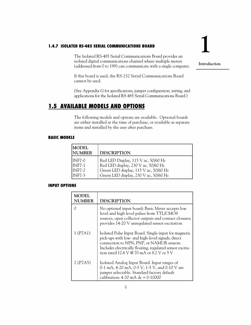
1.4.7 ISOLATED RS-485 SERIAL COMMUNICATIONS BOARD
The Isolated RS-485 Serial Communications Board provides anisolated digital communications channel where multiple meters(addressed from 0 to 199) can communicate with a single computer.
If this board is used, the RS-232 Serial Communications Boardcannot be used.
(See Appendix G for specifications, jumper configuration, wiring, andapplications for the Isolated RS-485 Serial Communications Board.)
1.5 AVAILABLE MODELS AND OPTIONS
The following models and options are available. Optional boardsare either installed at the time of purchase, or available as separateitems and installed by the user after purchase.
BASIC MODELS
MODELNUMBER DESCRIPTION
INF7-0 Red LED Display, 115 V ac, 50/60 HzINF7-1 Red LED display, 230 V ac, 50/60 HzINF7-2 Green LED display, 115 V ac, 50/60 HzINF7-3 Green LED display, 230 V ac, 50/60 Hz
INPUT OPTIONS
MODELNUMBER DESCRIPTION
0 No optional input board; Basic Meter accepts lowlevel and high level pulses from TTL/CMOSsources, open collector outputs and contact closures;provides 14-20 V unregulated sensor excitation
1 (P7A1) Isolated Pulse Input Board. Single-input for magneticpick-ups with low- and high-level signals; directconnection to NPN, PNP, or NAMUR sensors.Includes electrically floating, regulated sensor excita-tion rated 12.6 V @ 70 mA or 8.2 V or 5 V
2 (P7A5) Isolated Analog Input Board. Input ranges of0-1 mA, 4-20 mA, 0-5 V, 1-5 V, and 0-10 V arejumper selectable. Standard factory defaultcalibration: 4-20 mA dc = 0-10000

6
1Introduction
CONTROL/BCD OUTPUT OPTIONS
MODELNUMBER DESCRIPTION
0 No optional output board; standard five open-collector outputs
1 (BCD1) Isolated Parallel BCD (Binary-Coded Decimal)Output Board
2 (REL1) Dual Relay Output Board; Two 7-amp,Form-C Relays
3 (REL4) 4 Relay Output Board; Two 7-amp & two 1 ampForm-C Relays.
NOTE: Choose only one Control/BCD output option per meter.A 40-socket plug is included with the BCD option.
ANALOG OUTPUT OPTIONS
MODELNUMBER DESCRIPTION
0 No analog output board1 (ANO2) Isolated Analog Output Board: Configurable output;
0-20 mA, 4-20 mA, 0-5 V, 0-10 V. Standard factorydefault calibration: 0-10000 = 4-20 mA dc
DATA COMMUNICATIONS OPTIONS
MODELNUMBER DESCRIPTION
0 No serial communications board1 (RS21) Isolated RS-232 Serial Communications Board*2 (RS41) Isolated RS-485 Serial Communications Board**
NOTE: Choose only one option per meter. Both computercommunications come with a 6-foot communications cable withphone plug termination.
* We recommend purchase of 9SC2 or 25SC2 (see OPTIONSbelow)** We recommend purchase of 9SC4 or 25SC4 (see OPTIONSbelow)

1
7
Introduction
OPTIONS
MODELNUMBER DESCRIPTION
FS Custom Factory Calibration/ConfigurationBL Blank Front Panel Lens9SC2 9-pin Serial Connector for RS-232 port9SC4 9-pin Serial Connector for RS-485 port25SC2 25-pin Serial Connector for RS-232 port25SC4 25-pin Serial Connector for RS-485 portRP18 19-inch Rack Panel for 1 meterRP28 19-inch Rack Panel for 2 metersRP38 19-Inch Rack Panel for 3 meters

8
2Setup
2.1 UNPACKING
Unpack all items and make sure that every item on the packing listis present. The items you should receive are listed below. Ifsomething is missing, use the phone number for the CustomerService Department nearest you.
Also, inspect the shipping container and enclosed equipment for anysigns of damage. Take particular note of any evidence of roughhandling in transit. Immediately report any damage to the shippingagent.
NOTE: The shipping agent will not honor any claims unless allshipping material is saved for their examination. After examiningand removing contents, save all packing material and containers inthe event that reshipment is required.
You should receive the following items :
QTY DESCRIPTION ILLUSTRATION
1 Basic meter withmain board (andoptional boards ifordered by number);in plastic case withsleeve, panelgasket, twothumbnuts
1 Front-panelbutton cover availablewith return of thepostcard (see meter box)
2. Setup

2
9
Setup
QTY DESCRIPTION ILLUSTRATION
1 Orange, 3-socketpower connector (P1);for AC input
1 Gray, 3-socketinput connector (P3);for signal input
1 Rear cover withholddown screw
1 20-Socket RibbonConnector (P2)
2 Panel-mount gasket(1 spare)
1 Operator’s manual
123
123
N
L

10
2Setup
MODEL:SERIAL NO.:PART NO.:VOLTS: WATTS:
2.2 SAFETY PRECAUTIONS
The meter is protected in accordance with Class I of EN61010.Refer to Safety Considerations page.
WARNING: If your meter is to be wired to sensors or to controlinputs that could have hazardous potentials, these potentials will becarried to the 20-pin output connector (P2) at the rear. They willalso be present on the meter’s circuit boards. Follow all instructionscarefully, inserting the electronics into the case and installing connec-tors BEFORE connecting the meter to any source of power.
DO NOT contact any exposed metal parts, install optional board(s),change jumpers, or in any way disassemble or assemble the meterwhile it is connected to AC voltage.
Note the following information and guidelines for safe operation ofyour meter:
2.2.1 POWER VOLTAGE
Your power source voltage rating should agree with the voltageunder which the meter has been configured to operate. The firstthing you should do is verify this.
The meter’s operating voltage is shown in the VOLTS: entry ofthe ID and Serial Number Label. Figure 2-1 shows a copy of thislabel. It is located on the meter packing box and is clearly visible.(Another label is also affixed to the meter case.)
Figure 2-1. ID and Serial Number Label showing the Meter'soperating voltage.
!

2
11
Setup
2.2.2 POWER WIRING
CAUTION: The meter has no power-on switch; it will be ONwhen power is applied.
Section 2.3.5 shows you how to wire not only the AC powerconnector, but all other connectors as well.
2.3 ASSEMBLY/DISASSEMBLY
2.3.1 OPENING THE METER
Your meter is fully assembled, but not wired. In most cases, if youhave ordered optional boards with the meter, these boards willalready be installed.
You will need to remove only the rear cover to complete wiring,but you will have to open the meter to do one or more of thefollowing:
WARNING: You must disconnect and turn-off the power andconnector signals before accessing the unit and installing optionalboards. Failure to do so may result in injury!
a. Check or reconfigure the Transformer Jumpers on the MainBoard so that they correspond to your line voltage (W1 and W2for 115 V ac, or W3 for 230 V ac). See Section 2.3.2.1.
b. Access jumpers on the Main and optional boards.See Section 2.3.2.
c. Install optional boards. See Section 2.3.3.
!
!

12
2Setup
Figure 2-2. Exploded View of the Meter
REARPROTECTIVECOVER
COVERMOUNTINGSCREW
SLEEVE
AC POWER BOARD
MAIN BOARD ASSY
CASE
BEZEL
GASKET
THUMBNUTS
SIGNAL CONNECTORBOARD

2
13
Setup
Using Figures 2-2 as a guide, follow these simple instructions toopen the meter:
IMPORTANT: Turn-off the power and input signals from theunit before proceeding. Failure to do so may result in injury!
1. Remove the cover mounting screw that secures the rear protectivecover to the meter, and remove the Rear Protective Cover.
If you are simply wiring the meter–but not checking jumpers orinstalling or removing boards–this is as far as the meter needs tobe disassembled. Go to Section 2.3.5.
2. Remove all wiring connectors from the rear of the meter.
3. Remove the two thumbnuts that secure the case to the sleeve.
4. Remove the sleeve completely by sliding it back from the frontbezel.
!

14
2Setup
Figure 2-4. Removing the Main Board Assembly from the Case
The meter is now disassembled to the point where you can checkand configure jumpers and install boards.
NOTE: When the sleeve is removed from the case in Step 5above, the Connector Label on the case will be exposed.See Figure 2-5. Use this label for reference when wiring or con-necting plugs.
6. Using Figure 2-4 as a guide, bend the side-panel detents on thecase outward and pull the board assembly out of the case by themounting screw stem.
These six steps are known as “accessing the Main Board assembly.”
MAIN BOARD ASSY
CASE
BEND DETENTS OUTWARDTO INSTALL MAIN BOARD
SIGNAL INPUTJUMPER LABEL
ID AND SERIALNUMBER LABEL
MOUNTINGSCREWSTEM
TO INSTALL
TO REMOVE

2
15
Setup
Figure 2-5. Connector Label
2.3.2 CHECKING AND INSTALLING JUMPERS
This section contains figures and instructions for checking andinstalling jumpers, but it gives full information on the Main Boardonly. If you have any optional boards, refer to the appropriateappendix for specific jumper information.
NOTE: When referring to jumpers and the corresponding boards,the view is from the REAR of the meter.
P2/CABLE CONNECTORALARM 1 OUTPUT
RESET-AALARM 3 OUTPUTTWICE LINE FREQ
ALARM, BATTERY RETURNRESET-BTEST TX
PULSE OUTPUTSTOP
RESET-C
ALARM V + INPUTALARM 2 OUTPUTALARM 4 OUTPUTALARM 5 OUTPUTDEBOUNCETEST RXDIGITAL RETURNHOLD / PRINT REQGATE INPUTBACKUP BATTERY +
P4/RS-232654321
N/CCOMM RTNRXTXRTSN/C
654321
N/CB RXA RXCOMM RTNB TX/RXA TX/RX
P4/RS-485
P6/RELAY P7/RELAY
P5 ANALOG OUT
123
123
123
NO1CM1NC1
NO2CM2NC2
RETURN4-20 mA0-10 V
P1/AC PWR
P9 & P3
CONNECT TO LOW VOLTAGE LIMITED ENERGY CIRCUITRY ONLY.
PULSE INPUTFILTERSIG IN HI LEVELPULL UP/DOWN
EXCITATIONSIG IN LO LEVELSIG RETURN
P6 P7P8
P9
P5P4P2
P1 P3
BCD1 1
1
1
11
... ...1
1 19
.........................
...... ...
...
135791113151719
123
LINENEUTRALAC GND
ANALOG INPUT+24 V EXCSIGNAL INRETURN
TESTTESTTEST
1
1 1
1 11
1
P18 for 4 RELAYP8
2468
101214161820

16
2Setup
2.3.2.1 MAIN BOARD JUMPERS
Using Figure 2-6 and Table 2-1, configure or check Main Boardjumpers.
CAUTION: The meter has no power-on switch; it will be inoperation as soon as you apply power. To change the factory presetjumpers, disconnect the power from the unit. Failure to do so mayresult in injury! The jumpers must be changed by specially trainedpersonnel.
Figure 2-6. Main Board Jumpers
DISPLAYBOARD
SIGNAL CONNECTORBOARD
(BEHINDJ13 PINS)
MAIN BOARD
J2
J1
J3
AC POWER BDW1
W3W2
S1
A
T1
J14
A
S2
J11 J10
J13
J12
W2 W1
W3
115 V ac
230 V ac
W7
W6
!

2
17
Setup
TABLE 2-1. MAIN BOARD JUMPERS
LOCATION, VIEWINGTHE BOARD FROM THE
JUMPER REAR OF THE METER FUNCTION
S1-A On the right, immediately Enables push buttons tobehind the Display board control lockout
programming
S2-A First two pins of J13 on Channels non-isolatedthe right side of the Main excitation out to P3-1;Board remove if input board used
W1 andW2 Left side Enables 115 V operation
W3 Left side Enables 230 V operation
W6 andW7 Right side of Main Board Bypasses isolation circuitry
next to J13 used for option boards;remove if input board used
If your line voltage is 115 V ac, jumpers W1 and W2 (but NOTW3) should be installed.
If your line voltage is 230 V ac, jumper W3 (but NOT W1 or W2)should be installed.
NOTE: When referring to jumpers, the letter S means “switch”and the letter W means “wire.” Switch jumpers are caps that bridgetwo pins; they can easily be moved from one position to another.Wire jumpers are soldered in; they must be cut when “removed”and resoldered if reinstalled.
If no optional input board is used, jumper S2-A should be installedon the first two pins of J13. This jumper brings non-isolatedexcitation out to the P3-1 connection. Wire jumpers W6 and W7should also be in place. These jumpers bypass the isolation circuitryused for optional boards. See Figure 2-6.

18
2Setup
If one of the optional input boards is used, S2-A should be removed(or be installed on only one pin), and W6 and W7 should beremoved.
S1-A allows front-panel control of the three lockouts so that youcan lock and unlock meter features. You may want to remove thisjumper later to lock in certain settings that you don’t want to bechanged. (See Section 5.3.) It should be installed when the meteris first configured.
2.3.2.2 OPTIONAL INPUT AND OUTPUT BOARD JUMPER INFORMATION
JUMPER(S) CONFIGURINGBOARD TYPE PRESENT INFORMATION NOTES
Isolated pulse input Yes Appendix B –
Isolated analog input Yes Appendix C A one-timecalibration isneeded wheninstalled thefirst time.
Isolated analog output No Appendix D A one-timecalibration isneeded wheninstalled thefirst time.
Isolated ParallelBCD output Yes Appendix E –
Dual relay output Yes Appendix F –and 4 Relay output
Isolated RS-232 SerialCommunicationsOutput No Appendix G –
Isolated RS-485 SerialCommunicationsOutput Yes Appendix G –

2
19
Setup
2.3.3 INSTALLING OPTIONAL BOARDS
NOTE: When referring to installing optional boards, the view isfrom the REAR of the meter.
Figure 2-7 shows the Main Board and Figure 2-8 shows an explodedview of the meter with the optional board locations. In Figure 2-7,the “front” of the board refers to the side with the Display Board;the back is the side with J1 and J2 connections. Refer to Figures 2-7and 2-8 as you insert optional boards. All boards must be jumperedbefore insertion. See Section 2.3.2.
Figure 2-7. Main Board
DISPLAYBOARD
REAR
FRONT
SIGNAL CONNECTORBOARD
MAIN BOARD
J2
J1
J3
AC POWER BD
T1
J14
J11 J10
J13
J12

20
2Setup
Figure 2-8. Exploded View of Main and Optional Boards
BCD or 4 RELAY BOARD
INTERCONNECT BOARD(PART OF BCD ASSY)
REARPROTECTIVECOVER
COVERMOUNTINGSCREW
DUALRELAY BOARD
RETAINER (ALWAYS USED EXCEPT FOR BCD OR 4 RELAY OPTION)
THUMBNUTS
RS-232/RS-485 BOARD
ISOLATED ANALOGOUTPUT BOARD
SLEEVE
GASKET
MAIN BOARD ASSY
BEND DETENTS OUTWARDTO INSTALL MAIN BOARD
CASE
J20
P10 (4 RELAY BOARD ONLY)
P20
P14
P12
P11
J12 J11 J10
J14
P10
AC POWER BOARD
P13
PULSEINPUT BOARDOR ANALOGINPUT BOARD
SIGNAL CONNECTORBOARD
J13

2
21
Setup
2.3.3.1 ISOLATED PULSE INPUT BOARD
The Isolated Pulse Input Board plugs into J13 on the right side ofthe Main Board. J13 consists 10-pins with a gap at pin 5.
Figure 2-9. Isolated Pulse Input Board
Follow these steps before installing the board:
1. Remove (or connect to a single pin) jumper S2-A, the blackjumper clip on the first two pins of J13 on the Main Board.
2. Remove wire jumpers W6 and W7, the two soldered-in connec-tions to the immediate right of J13.
3. Plug the input board onto the J13 jack.
The Pulse Input Board and Analog Input Board can be installedat J13. However, only one can be installed at a time.
Refer to Appendix B to configure this board.
A DB C
S1
J9E
S1
P13
PIN 1
F

22
2Setup
2.3.3.2 ISOLATED ANALOG INPUT BOARD
The solder side of the Isolated Analog Input Board containscalibration data for precisely calibrating the board. Make sure youcopy the data before you install the board. Record them here:
Input 1 @ 4 mA =
Input 2 @ 20 mA =
Input 1 @ 0 V =
Input 2 @ 5 V =
The Isolated Analog Input Board plugs into J13 also. See section2.3.3.1, Steps 1 through 3.
Figure 2-10. Isolated Analog Input Board
The Analog Input Board and Pulse Input Board can be installedat J13. However, only one can be installed at a time.
Refer to Appendix C to configure this board.
J9
S1
P13S2
S2
PIN 1
AB
C
DE
A BC

2
23
Setup
2.3.3.3 ISOLATED ANALOG OUTPUT BOARD
The solder side of the Analog Output Board contains calibrationdata for precisely calibrating the board. Make sure you copy thedata readings–CAL VZ (Calibrate Voltage Zero), CAL VS (Cali-brate Voltage Span), CALmAZ (Calibrate milliAmp Zero), andCALmAS (Calibrate milliAmp Span)–before you install the board.Record them here:
CAL VZ =
CAL VS =
CALmAZ =
CALmAS =
The Analog Output Board plugs into J12, between J13 (on theright edge of the Main Board) and the transformer. J12 consists of8 pins with a gap at pin 6.
NOTE: Future analog output boards will be supplied with a 10-pinconnector for use with a DC powered version of this instrument.
Figure 2-11. Isolated Analog Output Board
Refer to Appendix D to configure this board.
723
V Z=
S=
Z=
S=
mA
130 m
715
12125
PIN 1
CAL VZ
CAL VS
CALmAZ
CALmAS
PIN 1
P12
P5

24
2Setup
2.3.3.4 ISOLATED PARALLEL BCD (BINARY-CODED DECIMAL) OUTPUT BOARD
The Isolated Parallel BCD Output Board mounts above (andparallel to) the Main Board using the small vertical InterconnectorBoard as a support. Note that this board is inserted component-side down.
S1 S2
S4
S5
A A
A B
A
C
E
G
S3A B
S6 B
A
B
A S7
S8
A
B
J20
PIN 1
L1U1
J8
Figure 2-12. Isolated Parallel BCD Output Board
1. Insert the P14 plug of the Interconnect Board onto the J14 pinson the Main Board. J14 consists of 5 vertical pins on the left sideof the Main Board, immediately behind the Display Board.
2. Insert the P20 connector of the Interconnect Board onto the J20pins on the BCD Board. (See Figure 2-8.)
The Dual Relay or 4 Relay Output Option may not be installedat the same time as the Parallel BCD Output Option.
Refer to Appendix E to configure this board.
2
25
Setup
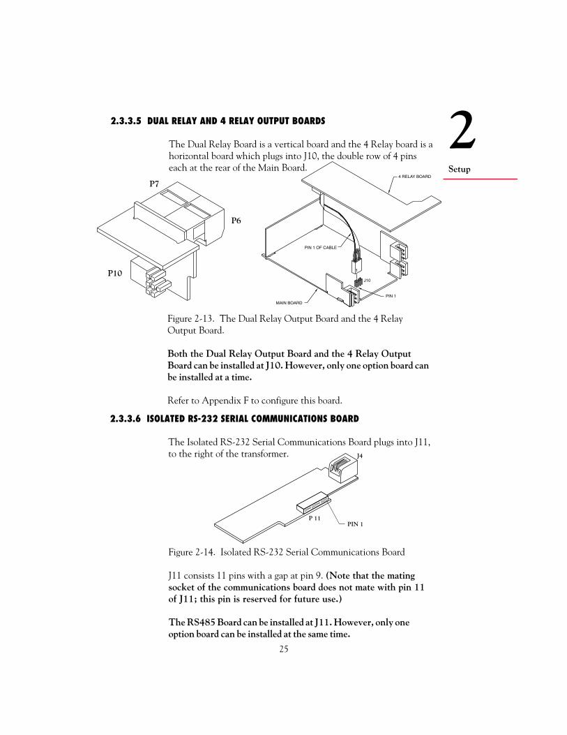
2.3.3.5 DUAL RELAY AND 4 RELAY OUTPUT BOARDS
The Dual Relay Board is a vertical board and the 4 Relay board is ahorizontal board which plugs into J10, the double row of 4 pinseach at the rear of the Main Board.
Figure 2-14. Isolated RS-232 Serial Communications Board
J11 consists 11 pins with a gap at pin 9. (Note that the matingsocket of the communications board does not mate with pin 11of J11; this pin is reserved for future use.)
The RS485 Board can be installed at J11. However, only oneoption board can be installed at the same time.
J4
PIN 1P 11
Figure 2-13. The Dual Relay Output Board and the 4 RelayOutput Board.
Both the Dual Relay Output Board and the 4 Relay OutputBoard can be installed at J10. However, only one option board canbe installed at a time.
Refer to Appendix F to configure this board.
P6
P7
P10
2.3.3.6 ISOLATED RS-232 SERIAL COMMUNICATIONS BOARD
The Isolated RS-232 Serial Communications Board plugs into J11,to the right of the transformer.
4 RELAY BOARD
PIN 1 OF CABLE
PIN 1
MAIN BOARD
J10

26
2Setup
2.3.3.7 ISOLATED RS-485 SERIAL COMMUNICATIONS BOARD
The Isolated RS-485 Serial Communications Board mounts in amanner identical to that of the RS-232 board in the previoussection.
Figure 2-15. Isolated RS-485 Serial Communications Board
The RS232 Board can be installed at J11. However, only oneoption board can be installed at the same time.
Refer to Appendix G to configure this board.
2.3.4 REINSERTING THE MAIN BOARD ASSEMBLY INTO THE CASE
Reinsert the Main Board into the case once Main Board jumpershave been configured (Section 2.3.2.1) and optional boards havebeen configured and installed (Sections 2.3.2.2 through 2.3.3).
Spread the side-panel detents of the case, and carefully slide theMain Board all the way in.
You are now ready to wire your meter.
2.3.5 WIRING
The way you connect your input wiring to your meter depends onyour pulse or input source, and the types of optional boards youhave installed. Therefore, this section contains complete instruc-tions for wiring only the AC Power connector (P1), and guidelinesfor wiring the input/output control connector (P2). You will bereferred to the appropriate appendix for specific wiring instructionsbased on your optional board configuration.
S1A B
S3
A
S2A
J4
PIN 1P11
2
27
Setup
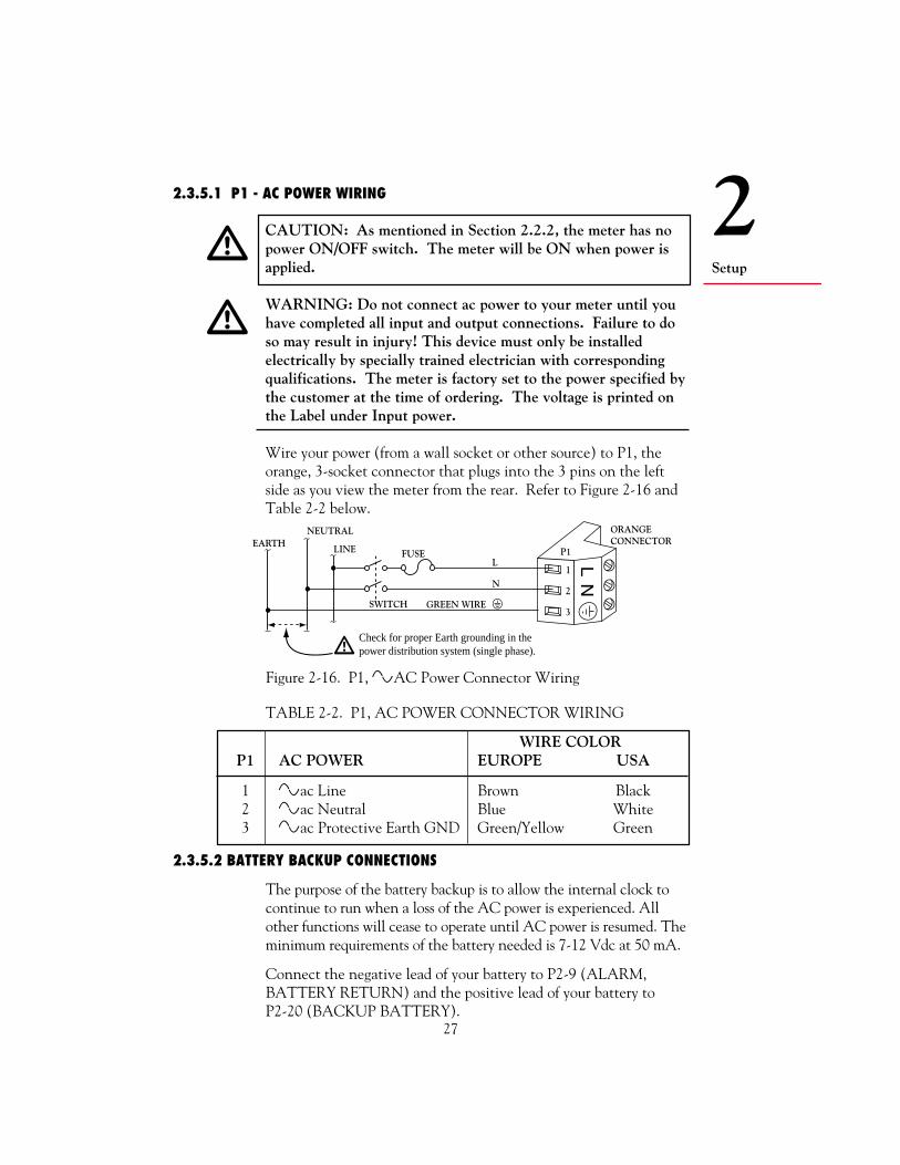
TABLE 2-2. P1, AC POWER CONNECTOR WIRING
WIRE COLORP1 AC POWER EUROPE USA
1 ac Line Brown Black2 ac Neutral Blue White3 ac Protective Earth GND Green/Yellow Green
2.3.5.1 P1 - AC POWER WIRING
CAUTION: As mentioned in Section 2.2.2, the meter has nopower ON/OFF switch. The meter will be ON when power isapplied.
WARNING: Do not connect ac power to your meter until youhave completed all input and output connections. Failure to doso may result in injury! This device must only be installedelectrically by specially trained electrician with correspondingqualifications. The meter is factory set to the power specified bythe customer at the time of ordering. The voltage is printed onthe Label under Input power.
Wire your power (from a wall socket or other source) to P1, theorange, 3-socket connector that plugs into the 3 pins on the leftside as you view the meter from the rear. Refer to Figure 2-16 andTable 2-2 below.
Figure 2-16. P1, ~AC Power Connector Wiring
LFUSE
N
SWITCH
P1
1
2
3
ORANGECONNECTOR
LN
[GREEN WIRE
EARTHLINE
NEUTRAL
Check for proper Earth grounding in the power distribution system (single phase).
2.3.5.2 BATTERY BACKUP CONNECTIONS
The purpose of the battery backup is to allow the internal clock tocontinue to run when a loss of the AC power is experienced. Allother functions will cease to operate until AC power is resumed. Theminimum requirements of the battery needed is 7-12 Vdc at 50 mA.
Connect the negative lead of your battery to P2-9 (ALARM,BATTERY RETURN) and the positive lead of your battery toP2-20 (BACKUP BATTERY).
!
!

28
2Setup
2.3.5.3 P2 - CONTROL INPUT/OUTPUT WIRING
P2, the 20-socket ribbon connector plugs into the center rear of theMain Board, sends out the setpoint transistor collectors and permitsremote control of significant meter features. Table 2-3 describesthe function of each pin.
TABLE 2-3. P2, INPUT/OUTPUT CONNECTIONS
P2SOCKET/PIN NO. DESCRIPTION/FUNCTION
P2-1 Setpoint 1 transistor open-collector outputP2-2 Input of external V+ used for setpoint transistors so that
internal diodes can clamp inductive-load spikesP2-3 RESET-A: When grounded in Rate or Sq Rt Modes,
resets TOTAL to 0, resets TOTAL setpoint latches; inBatch Mode, starts a new BATCH count, incrementsBAT NO (Number of Batches), resets BATCH-countsetpoint latches, and clears any STOP (See Section 4.10)
P2-4 Setpoint 2 transistor open-collector outputP2-5 Setpoint 3 transistor open-collector outputP2-6 Setpoint 4 transistor open-collector outputP2-7 Twice-line-frequency, 5-V pulse output (also used by
microcontroller to detect line failure)P2-8 Setpoint 5 transistor open-collector outputP2-9 Return ground connection: SP-transistor external supply
and/or backup battery groundP2-10 Debounce capacitor for P3-2 signal input (tie to ground
for contact input)P2-11 RESET-B: When grounded in Rate or Sq Rt Modes,
starts a new AVG RTE (Average Rate) period, resetsRATE setpoint latches; in Batch Mode, resets BAT NO(Number of Batches) to 0 (if count is up) or toSetpoint 4 value (if count is down), and resetsBAT NO setpoint latches (if SP4 has been assigned)(See Section 4.10)
P2-12 TTL-level Test RXP2-13 TTL-level Test TXP2-14 Meter digital ground (internally connected to P2-9)P2-15 Programmable Pulse Output (see AL TI, Section 5.4.12)
continued next page
2
29
Setup
P2SOCKET/PIN NO. DESCRIPTION/FUNCTION
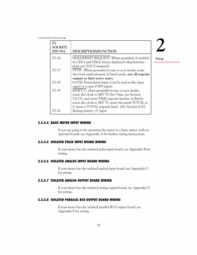
P2-16 HOLD/PRINT REQUEST: When grounded, if enabledby CF4.3 and CF4.4, freezes displayed value/initiatesprint out (V01 Command)
P2-17 STOP: When grounded in rate or sq rt modes, stopsthe clock until released; in batch mode, sets all setpointoutputs to their active states
P2-18 GATE: Nonisolated input: Can be used as the inputsignal or to gate P3/P9 inputs
P2-19 RESET-C: when grounded in rate or sq rt modes,resets the clock to SET TI (Set Time, see Section5.4.15), and resets TIME setpoint latches; in Batch,resets the clock to SET TI, resets the grand TOTAL to0, resets a TOTAL setpoint latch (See Section 4.10)
P2-20 Backup battery +V input
2.3.5.4 BASIC METER INPUT WIRING
If you are going to be operating the meter as a basic meter–with nooptional boards–see Appendix A for further wiring instructions.
2.3.5.5 ISOLATED PULSE INPUT BOARD WIRING
If your meter has the isolated pulse input board, see Appendix B forwiring.
2.3.5.6 ISOLATED ANALOG INPUT BOARD WIRING
If your meter has the isolated analog input board, see Appendix Cfor wiring.
2.3.5.7 ISOLATED ANALOG OUTPUT BOARD WIRING
If your meter has the isolated analog output board, see Appendix Dfor wiring.
2.3.5.8 ISOLATED PARALLEL BCD OUTPUT BOARD WIRING
If your meter has the isolated parallel BCD output board, seeAppendix E for wiring.
continued from previous page

30
2Setup
2.3.5.9 DUAL RELAY OUTPUT AND 4 RELAY OUTPUT BOARD WIRING
If your meter has the Dual Relay Output Board or the 4 RelayOutput Board, see Appendix F for wiring.
2.3.5.10 ISOLATED RS-232 OR RS-485 SERIAL COMMUNICATIONS BOARD WIRING
If your meter has either the Isolated RS-232 or RS-485 SerialCommunications Board, see Appendix G for wiring or connections.
2.4 PANEL-MOUNT ASSEMBLY
The meter can be mounted in a panel so that the front of the meteris flush with the vertical panel surface. Panel mounting can beseen as simply “sandwiching” the panel between the inner case andthe outer sleeve in the last phases of assembly. Figure 2-17 showsthe panel cutout dimensions, and the dimensions for the panelthickness. It requires that the following already be done:
1. Your line voltage rating has been checked against the meterrating on the ID and serial number label on the meter case. SeeSection 2.2.1.
2. You have configured all jumpers–those on the main board as wellas those on any optional boards. See Section 2.3.2.1 for mainboard jumper configuration and Appendices B through G foroptional board jumper configuration.
3. You have installed all optional boards and inserted the mainboard assembly back into the case. See Sections 2.3.3 and 2.3.4.
4. You have wired P1, the AC power connector, and P2 the input/output control connector; connectors are not installed in themeter, but are ready to be. See Sections 2.3.5.1 and 2.3.5.2.
5. You have wired all connectors for optional boards; connectorsare not connected to the meter, but are ready to be. See Appen-dices B through G.
CAUTION: Connectors with the wiring connections will beinstalled after mounting the unit.
If all of these steps are done, continue here using Figure 2-17 as aguide:
!

2
31
Setup
Figure 2-17. Panel-Mount Assembly
REARPROTECTIVECOVER
COVERMOUNTINGSCREW
THUMBNUTS
SLEEVE
GASKET
CASE
BEZEL
PANEL
METER
1.772 +0.024/-.000[45.00 +0.61/-0.00]
3.622 +0.032/-.000[92.00 +0.81/-0.00]
PANEL CUTOUT
0.25 [6.4] MAX0.03 [0.8] MIN
PANEL THICKNESS
0.06[1.5]
4PLCS
R

32
2Setup
6. Punch or cut a hole in the panel using the panel cutoutdimensions in Figure 2-17. Remove burrs and paint the panelas required.
7. Insert the panel-mount gasket around the rear of the case andslide it forward to the bezel (if it’s not already in place).
8. Working from the front of the panel, insert the case assembly,rear end first, all the way into the panel cutout such that thegasket firmly backs the panel surface.
9. Working from the rear of the panel, slide the sleeve forwardover the case and up to the panel surface.
The panel should now be sandwiched between the bezel-backedgasket in front and the sleeve in back.
10. Replace the thumbnuts that secure the sleeve tabs to the case.
WARNING: Do not "turn-on" the ac power and input signalsuntil all connections are connected to the meter.
11. Set P1, the AC power connector, aside and connect or recon-nect all other connectors to the back of the meter using Figures3-2 and 3-3 in Section 3.2 as guides.
NOTE: The P1 connector is “keyed”; it is shaped in such a waythat it fits only the J1 male pins.
Connect P1 last.
12. Replace the rear protective cover and secure it with the covermounting screw.
Your meter is now ready for operation and you can turn-on thepower.
!

33
3Frontand RearFeatures
TABLE 3-1. FRONT-PANEL DISPLAYS AND BUTTONS
FRONT-PANELBUTTON OR
ITEM FEATURE DESCRIPTION/FUNCTION
1 6-Digit Display 6-Digit, 14-segment, 0.54-inch LEDdisplay produces alphanumeric readout;programmable decimal point; red withgreen option
2 Measurement Green LEDs; designate whichmeasurement is beingdisplayed (See DISPLAY, below)
3 Setpoint LEDs Red LEDs; designate which setpoints areactive; when flashing, designate whichsetpoint is being viewed and/or set
4 SETPTS Button In Run mode changes to Setpoint Modeand allows setting of five setpoints; allowsvalue change by pressing the /DISPLAYbutton and the /STOP button
3. Front and Rear Features
continued next page
3.1 FRONT-PANEL DISPLAYS AND BUTTONS
Refer to Figure 3-1 as you read about front panel displays andbuttons.
Figure 3-1. Front Panel
1
3 3
4 5 6 7 8
23
22
3

34
Frontand RearFeatures
3FRONT-PANELBUTTON OR
ITEM FEATURE DESCRIPTION/FUNCTION
5 /DISPLAY Two-Function button: In Run Mode,Button sequences the display through mode-
associated measurements; in Configura-tion and Setpoint Modes, sequencesthrough possible digit and numericalsettings• In Rate-Run Mode, sequences the
display through unlocked values ofRATE, AVG RT, TOTAL, and TIME
• In Sq Rt-Run Mode, sequences thedisplay through unlocked values ofSQ RT, AVG RT, TOTAL and TIME
• In Batch-Run Mode, sequences thedisplay through unlocked values ofBATCH, BAT NO, TOTAL and TIME
• In Setpoint and Configuration Modes,sequences through possiblealphanumeric settings: Fornumbers,increments the flashing digitby 1; for alphabetical settings,sequences to the next possible setting
6 /STOP Button Two-Function button: In run mode,(STOP enabled imposes STOP condition; in configura-by CF4.8=1) tion and setpoint modes, accesses the
next digit or choice• In batch-run mode, if CF4.8=1, puts
all setpoints in their ACTIVE statesand displays STOP. (After 3 seconds,the /STOP button can be pressedagain to reset alarms and return to runmode)
• Inactive in rate-run or sq rt-run modes• In setpoint mode advances the
flashing digit one place to the right,making the new digit accessible forresetting by the /DISPLAY button
continued from previous page
continued next page

35
3Frontand RearFeatures
FRONT-PANELBUTTON OR
ITEM FEATURE DESCRIPTION/FUNCTION
• In configuration mode, advances theflashing digit one place to the right,making the new digit accessible forresetting by the /DISPLAY button;advances the displayed choice to thenext choice in sequence
7 MENU Button • In run mode, terminates measure-(Enabled by ments and switches to ConfigurationL3C.8=0; Modedisabled by • In configuration mode, stores newL3C.8=1 and values in EEPROM (nonvolatileremoval of S1) memory) and advances the display to
the next parameter to be programmed
8 RESET Button • In Run Mode, RESETs the value of(Enabled by the measurement on display to zeroCF4.7=0) (or to the reset value designated by
configuration) Also RESETs anylatched alarms assigned to the displayed measurement
• In setpoint mode, switches back to runmode; any new setpoint values enteredwith the /STOP button and the/DISPLAY button that have notbeen stored are discarded
• In configuration mode, the first pressbacks up one parameter (Menu item);the second one RESETs the meter andreturns to run mode
continued from previous page
3.2 REAR CONNECTORSFigure 3-2 shows the rear of the meter with the Dual Relay Board,and a serial communications board. Figure 3-3 shows it with theIsolated Parallel BCD Output Board, a serial communicationsboard, Isolated Analog Output Board, and Analog or Pulse InputBoard. Figure 3-4 shows the connector label with pin assignments.

36
Frontand RearFeatures
3
123
P1
N
L
120
P2
123
P5
123
P3
P8U1
L1
U20L20123
P9J4
Figure 3-3. Rear View with the BCD, Serial Communications, andAnalog Output Boards
Figure 3-2. Rear View of the Meter with the 4-Relay andSerial Communications Boards
123
P1
N
L
P2
P6P7
J4
20
1
1 2 3
1 2 3
123
P3
123
P9
P18
1 2 3 4 5 6

37
3Frontand RearFeatures
TABLE 3-2. REAR CONNECTORS
CONNECTORNUMBER DESCRIPTION
P1 AC Power Connector; 3-socket connector for AC power input.
P2 Control Input/Output connector; 20-socket ribbonconnector sends out setpoint transistor collectors andallows remote control of certain meter features.
P2/CABLE CONNECTORALARM 1 OUTPUT
RESET-AALARM 3 OUTPUTTWICE LINE FREQ
ALARM, BATTERY RETURNRESET-BTEST TX
PULSE OUTPUTSTOP
RESET-C
ALARM V + INPUTALARM 2 OUTPUTALARM 4 OUTPUTALARM 5 OUTPUTDEBOUNCETEST RXDIGITAL RETURNHOLD / PRINT REQGATE INPUTBACKUP BATTERY +
P4/RS-232654321
N/CCOMM RTNRXTXRTSN/C
654321
N/CB RXA RXCOMM RTNB TX/RXA TX/RX
P4/RS-485
P6/RELAY P7/RELAY
P5 ANALOG OUT
123
123
123
NO1CM1NC1
NO2CM2NC2
RETURN4-20 mA0-10 V
P1/AC PWR
P9 & P3
CONNECT TO LOW VOLTAGE LIMITED ENERGY CIRCUITRY ONLY.
PULSE INPUTFILTERSIG IN HI LEVELPULL UP/DOWN
EXCITATIONSIG IN LO LEVELSIG RETURN
P6 P7P8
P9
P5P4P2
P1 P3
BCD1 1
1
1
11
... ...1
1 19
.........................
...... ...
...
135791113151719
123
LINENEUTRALAC GND
ANALOG INPUT+24 V EXCSIGNAL INRETURN
TESTTESTTEST
1
1 1
1 11
1
P18 for 4 RELAYP8
2468
101214161820
Figure 3-4. Connector Label
continued next page

38
Frontand RearFeatures
3CONNECTORNUMBER DESCRIPTION
P3 Input and Excitation connector; 3-socket input plug forunregulated excitation for Basic Meter; low levelinput and excitation for Isolated Pulse Input Board.Not used with Analog Input Board (test points forfactory use only).
P4 Isolated RS-232 or RS-485 Serial CommunicationsBoard connection for digital communications;6-spring RJ-12 telephone plug (for 7-foot cablefurnished with either board).
P5 Isolated Analog Output connector; 3-socket output plugfor optional analog output.
P6 and P7 Dual Relay and 4 Relay connector; 3-socket outputplugs for optional 7-amp, Form-C Relays.
P8 Isolated parallel BCD Output Board connector; 40-socketplug for optional BCD output; connects to ribbon cable.
P9 3-Socket optional input board connector; for Isolated PulseInput Board, high-level input and filter connections;for Isolated Analog Input Board, input, excitation,and common return.
P18 4 Relay connector; 6-socket output plug for optional 1-amp,Form-C relays.
continued from previous page
39
4BasicConcepts
4. Basic Concepts and Approaches to Setup and Configuration
Your application and what you need to accomplish will dictate setupand configuration of the meter. This section shows you how the meterworks; it contains information that will help you see how your metercan best be connected to peripheral devices, or to resets and alarms.
4.1 CHOOSING AN OPERATING MODE
One of the first decision you need to make is to determine whatMODE you want the meter to run in. There are two ratemodes—Rate and Sq Rt—that count per unit time, and onecounting mode—Batch.
If you need to measure a simple rate, you should use Rate Mode. Ifyour input signal is proportional to the square of the quantity thatyou are measuring, you should use Sq Rt mode. Differentialpressure transducers produce this type of input and almost alwaysrequire the use of the isolated analog input board. If you need tocount, especially on numerous levels, you should use Batch Mode.
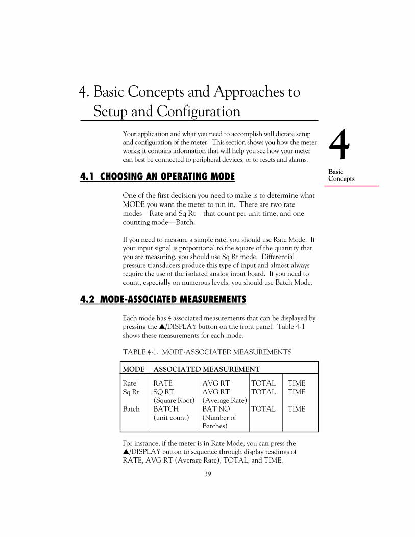
4.2 MODE-ASSOCIATED MEASUREMENTS
Each mode has 4 associated measurements that can be displayed bypressing the /DISPLAY button on the front panel. Table 4-1shows these measurements for each mode.
TABLE 4-1. MODE-ASSOCIATED MEASUREMENTS
MODE ASSOCIATED MEASUREMENT
Rate RATE AVG RT TOTAL TIMESq Rt SQ RT AVG RT TOTAL TIME
(Square Root) (Average Rate)Batch BATCH BAT NO TOTAL TIME
(unit count) (Number ofBatches)
For instance, if the meter is in Rate Mode, you can press the/DISPLAY button to sequence through display readings ofRATE, AVG RT (Average Rate), TOTAL, and TIME.

40
4Basic
Concepts
When any mode-associated measurement (except TIME) is on thedisplay, the corresponding Measurement LED is lit. The firstmeasurement in any mode (RATE, SQ RT, or BATCH) corre-sponds to the top LED.
The factory preset operating mode of the meter is Rate. Thefactory preset Rate units are Hertz–cycles per second–which themeter interprets as pulses per second.
4.3 USING SCALE FACTORS
One of the great features of the meter is that the input units can beconverted to units other than Hertz (frequency), and the associatedTOTAL can also have independent units. This is accomplished byusing scale factors.
Input units are converted to other display units by using a rate scalefactor (RTE SC) for Rate and Sq Rt Modes, or a Batch scale factor(BAT SC) for the Batch Mode. For instance, you are in RateMode, filling barrels of wine; you want to show the rate of filling ingallons per minute, but the total in barrels. You would use the RTESC parameter to convert the incoming signal from Hertz to gallonsper minute, and the TOT SC parameter to convert the total frompulses to barrels. When the meter is running and you press the/DISPLAY button to view readings, the RATE reading will be ingallons per minute, and the TOTAL reading in barrels.
4.4 USING OFFSETS
The meter allows you not only to scale RATE and TOTAL values,but to offset them as well. For instance, you have a dam that is1000 feet above sea level. You have scaled the incoming signal sothat the display reads in feet. Now you want to offset this readingso that it reflects the height above sea level. You would use a RateOffset (RTE OF) of 1000. When you press the /DISPLAYbutton to view the RATE reading, it will show the height of thewater above sea level.
4.5 AUTOMATIC SCALE AND OFFSET
The Automatic Scale and Offset feature is a function that auto-matically sets the scale factors of the input signal and the Ratereading to 1, and the offset values of the input signal and Rate

41
4BasicConcepts
reading to 0. It provides a quick way to “wipe out” scale factors andoffsets so that they can be reconfigured easily. This feature isenabled by setting configuration choice CF4.8 to 1. (See Section5.4.2.)
4.6 OVERFLOW VALUES AND EXPONENTIAL FORMAT
If your source signal units are Hertz, the meter is counting manypulses every second. This means that the TOTAL count can climbvery quickly. If you are in this or a similar situation, you willalmost always want to convert TOTAL units to other units thatscale down the count. When the meter encounters a count toolarge to show on the 6-digit display, it begins using exponentialformat like this:
3.23 E8
The E designates the exponent of 10. In this example 3.23 E8 =3.23 * 108 = 323000000. The exponent power can be seen as thenumber of places the decimal point should be moved to the right.
4.7 NEGATIVE-TRUE LOGIC
In places throughout this manual, you will see a bar over certainwords, like this:
RESET-A
This bar indicates Negative-true logic, also referred to as a NOTcondition. This means that the indicated function must “go low”to be activated. In the example above, your input voltage to theconnector pin that controls a RESET-A must be low in order toactivate the reset.
4.8 DIFFERENT METER MODES
Modes are ways in which the meter operates or can be configured.
1. Run Mode is the generic term that defines the operating mode ofthe meter when it is not being configured or at a STOP. Thereare four kinds of Run Modes: Rate, Sq Rt, Batch, and Clock.(Since Clock always runs in the background, it is notconfigurable as a Run Mode.)

42
4Basic
Concepts
Run Mode is accessed under the following conditions:
a. Whenever power is applied to the meterb. When the RESET button is pressed twice in the middle of the
Parameter list, (or three times if the display shows a submenu) inConfiguration Mode
c. At the end the Parameter list in Configuration Moded. At the end of the setpoint sequence in Setpoint Modee. After a 3-second STOP has been initiated (and terminated when
the /STOP button is pressed again) in Batch-Run Mode
Whenever the meter starts operating in, or reverts to, Run Mode,the word RUN momentarily shows on the display. If the meter isin Rate, Sq Rt, or Batch Mode, one of the Measurement LEDs isalso lit.
2. Configuration Mode is the mode that allows you to configure themeter. It is accessed by pressing the MENU button. Mostsetpoint assignments can be configured in this mode; the onlyassignments that cannot be configured are the setpoint values.See Section 5 for more information on configuring the meter.
3. Setpoint Mode. This mode allows you to configure the setpointvalues only. It is accessed by pressing the SETPTS button. Seethe Section 4.9 for more information on setpoints.
4.9 SETPOINTS
One of the most important functions of the meter is to monitorcounts and rates, and at certain pre-determined values, initiateappropriate responses. These pre-determined values are calledsetpoints and the responses they initiate may be alarms, resets, orany other type of action that must be carried out at a certain time.
The meter has a total of 5 setpoints, numbered in sequence—Setpoint 1, Setpoint 2, etc. Each one is associated with a transistorthat brings about a response.
4.9.1 SETPOINT ASSIGNMENTS
In a strict sense, setpoints are nothing more than reference pointsawaiting assignments. Each one must be assigned the followingattributes or characteristics:

43
4BasicConcepts
1. A specific measurement (such as TOTAL) to which it applies
2. A setpoint value: a specific value that when crossed causes thesetpoint to become “active”
3. A directional reference indicating whether the setpoint is activeABOVE or BELOW the setpoint value
4. The normal state (open or closed) of the associated transistor
5. The type of output (normal, latched, or pulsed) that is initiatedwhen the setpoint is activated. In Rate and Sq Rt Modes, outputcan also be hysteretic.
When the Dual Relay Board is used, setpoints are assigned intogroups of 3 and 2 each, and one set point in each group is assignedto a specific relay by positioning the S1 jumpers on the relay board.See Appendix F for more information.
Certain setpoints are always associated with certain RESETs. InBatch Mode, when counting down, the Setpoint 3 value is alwaysused when an Autoreset or a RESET-A is initiated.
Table 4-2 shows which setpoints are assigned to which measure-ment in each mode:
TABLE 4-2. SETPOINT ASSIGNMENTS FOR EACH MODE
MODESETPOINT RATE SQ RT BATCH
1 TOTAL TOTAL BATCH Count2 TOTAL TOTAL BATCH Count3 RATE RATE BATCH Count4 RATE RATE BAT NO or TOTAL5 TIME TIME TIME
For example, if you are in Rate Mode, you can use Setpoints 1 and2 to trigger appropriate responses based on the TOTAL reading.
44
4Basic
Concepts
4.9.2 CONFIGURING SETPOINTS
All setpoint assignments except for the setpoint value are configuredwith parameters CNFG 1 through CNFG 3 (see Section 5). They areset to specific values through the SETPTS button on the front panel.
To set any setpoint value from Run Mode, press the SETPTSbutton. The display will momentarily show STPT 1, then displaythe current setting. Press the /STOP button to move to any digit,and the /DISPLAY button to set the digit. Press the SETPTSbutton to store the setting and to move to the next setpoint. Themeter will automatically reset and revert to Run Mode at the end ofthe setpoint sequence.
NOTE: Once you are in the setpoint configuration mode and youdo not press any buttons within approximately 30 seconds, themeter will automatically return to the run mode.
Setpoints 1 through 4 have corresponding LEDs that light whenthey are accessed or activated in Run Mode.
4.10 RESETS AND STOPS
Resets are actions that cause a measurement value to revert to aspecific number, or a meter condition to revert to a specific state.They are often used to start a counting cycle over and to deactivatealarms. Resets can be automatic, initiated by setpoints or controldevices connected to the meter through the P2 connector; ormanual, initiated by the front-panel RESET button, or by anexternal button connected to P2-2.
4.10.1 POWER-ON (HARD) RESETA power-on or hard reset occurs when power is restored to themeter. It loads (copies) nonvolatile memory values into operatingmemory and resets measurement values. The TIME display flashesshowing the last time count.
4.10.2 CONFIGURATION (COLD) RESETA cold reset loads new nonvolatile memory settings into operatingmemory after the meter has been configured or setpoint values havebeen changed. (Lockout L3C.7 must be set to 0 to enable storageof new settings in nonvolatile memory.) A cold reset resets allmeasurement values except TIME, and the meter reverts to RunMode using the new settings. It is done by pressing the RESET

45
4BasicConcepts
button two times during configuration. It is also done automaticallyafter the last parameter is viewed and saved in Configuration Mode.
A cold reset can also be done through serial communications. Referto the Serial Communications Manual for additional information.
4.10.3 SETPOINT-ONLY RESET
A Setpoint-Only Reset returns the meter to Run Mode afterwriting new setpoint values in operating memory only. New valuesare prevented from being stored in nonvolatile memory by pur-posely setting Lockout L3C.7 to 1. This condition is desirablewhen setpoints are changed very often. Locking out nonvolatilememory storage assures that the EEPROM chip’s life isn’t short-ened by constant setpoint changes. The meter continues to usevalues set in this way until power is disconnected.
A Setpoint-Only Reset is done by changing setpoints with theSETPT button, then pressing the RESET button. The NOSTORerror message will appear on the display, indicating that setpointvalues have not been stored in nonvolatile memory.
4.10.4 RATE AND SQ RT MODE RESETS
NOTE: Access to configuration bits (i.e. CF1.2, CF2.1, CF3.3 andCF4.1) are via the configuration menus CNFG 1, CNFG 2,CNFG 3 and CNFG 4.
4.10.4.1 RESET-A
RESET-A is activated through the P2-3 pin on the 20-socketribbon connector at the rear of the Main Board. It can be config-ured to act either on the pulse edge (CF4.1=0) or pulse level(CF4.1=1). It does the following:
1. Resets the TOTAL counter to 0; the display will reflect anyTOT OF (Total Offset) value.
2. Unlatches a latched alarm (output) assigned to TOTAL (whenCF3.3 and CF3.4=1).
3. Terminates a pulsed alarm (output) assigned to TOTAL if theassociated setpoint is not designated in the AL TI (Alarm Time)parameter. RESET-A does not terminate a pulsed alarm if theassociated setpoint is assigned a pulse duration in the AL TIparameter.

46
4Basic
Concepts
4.10.4.2 RESET-B
RESET-B is activated through P2-11. It does the following:
1. Makes the AVG RT (Average Rate) equal to the latest RATEmeasurement (starts a new AVG RT period)
2. Unlatches a latched alarm (output) assigned to RATE (Setpoints3 and 4)
3. Resets the hysteresis action as follows:
If active BELOW, compares reading with Setpoint 3.
If active ABOVE, compares reading with Setpoint 4.
4. Terminates a pulsed alarm (output) assigned to RATE if theassociated setpoint is not designated in AL TI.
4.10.4.3 RESET-C
RESET-C is activated through P2-19. It sets the TIME to theconfigured SET TI (Set Time) value.
4.10.4.4 FRONT-PANEL RESET
The front-panel reset is activated by pressing the RESET button.It can be disabled by setting the CF4.7 choice to equal “1”. Itinitiates the actions of RESET-A, RESET-B, or RESET-C, depend-ing upon which measurement is displayed.
Table 4-3 shows the reset function for the measurement displayedin the RATE, AVERAGE RATE, TOTAL or TIME both standardand square-root modes
TABLE 4-3. FRONT-PANEL RESETS IN RATE AND SQ RT MODES
DISPLAYEDMEASUREMENT RESET FUNCTION
RATE RESET-B (but does not change AVG RT)AVG RT Replaces AVG RT with latest RATETOTAL RESET-ATIME RESET-C
47
4BasicConcepts
4.10.5 BATCH MODE RESETS
4.10.5.1 RESET-A
RESET-A is activated through the P2-3 pin on the 20-socketribbon connector at the rear of the Main Board. It can be config-ured to act either on the pulse edge (CF4.1=0) or pulse level(CF4.1=1). It does the following:
1. Resets the BATCH counter to 0 if the meter is counting up(CF1.8=0); resets to the Setpoint 3 value if the meter is count-ing down (CF1.8=1)
2. Increments BAT NO (Number of Batches) by 1.
3. Unlatches a latched alarm (output) assigned to BATCH (whenCF3.3=1 and CF3.4=1) and removes a STOP condition initiatedby either the front-panel /STOP button or P2-17.
4. Terminates a pulsed alarm (output) assigned to BATCH if theassociated setpoint is not designated in the AL TI (Alarm Time)parameter.
RESET-A does not terminate a pulsed alarm if the associatedsetpoint is assigned a pulse duration in the AL TI parameter.
4.10.5.2 RESET-B
RESET-B is activated through P2-11. It does the following:
1. Resets the BAT NO (Number of Batches) to 0 if the meter iscounting up (CF2.7=0) or to the Setpoint 4 value if the meter iscounting down. (When counting down, SP 4 must be assignedto BAT NO).
2. Unlatches a latched alarm (output) assigned to BAT NO.
3. Terminates a pulsed alarm (output) assigned to BAT NO if theassociated setpoint is not designated in the AL TI (Alarm Time)parameter.
4.10.5.3 RESET-C
RESET-C is activated through P2-19. It does the following:
1. Resets the TOTAL counter to 0; the display will reflect anyTOT OF (Total Offset) value.
2. Unlatches a latched alarm (output) assigned to TOTAL.
3. Sets the TIME to the configured SET TI value (if CF4.7=0).

48
4Basic
Concepts
4.10.5.4 FRONT-PANEL RESET
The front-panel reset is activated by pressing the RESET button.It can be disabled by setting the CF4.7 choice to 1. It initiates theactions of RESET-B, or RESET-C, depending upon which measure-ment is displayed.
Table 4-4 shows the front-panel reset functions for the BATCH mode.
TABLE 4-4. FRONT-PANEL RESETS IN BATCH MODE
DISPLAYEDMEASUREMENT RESET FUNCTION
BATCH Loads B LOAD ValueBAT NO RESET-BTOTAL Resets the total counter to zeroTIME Resets time to SET TI value
A front-panel RESET also unlatches a possible latched alarm.
4.10.5.5 AUTORESET
Autoreset is a specific type of automatic reset. It is an internalRESET-A. It uses 0 and the Setpoint 3 value exactly like RESET-A:
Resets the BATCH counter to 0 if the meter is counting up(CF1.8=0); resets to the Setpoint 3 value if the meter is countingdown (CF1.8=1).
You must set the CF2.6 choice to 1 to enable the Autoreset function.
4.10.6 STOP
The front-panel /STOP button works only in Batch Mode. Ifconfiguration choice CF4.8=1, the button is enabled; pressing itactivates all setpoints, which should trigger alarms that halt orsafeguard the system. After 3 seconds, pressing the /STOPbutton again resets all alarms and returns the meter to Run Mode.
4.11 COUNTING UP OR DOWN
Another decision you will have to make when setting up the meteris whether you want to count up or down. Generally, counting upis easier than counting down.

49
4BasicConcepts
For instance, you’re baking a batch of pies and you know that thepies must be in the oven for 45 minutes. You have two options:You can count up from 0, and at 45 minutes perform a reset thatsets the time back to 0; or you can count down from 45, and at 0perform a reset that sets the time back to 45.
If you are using the Rate Mode or Sq Rt Mode, counting up anddown applies to the TOTAL count only. In Batch mode, countingup and down applies to all counts, BATCH, BAT NO, andTOTAL.
Note that most counting routines involve interdependent reset,setpoint, and configuration settings.
4.11.1 COUNTING UP
For TOTAL counts, the meter counts UP by using the followingequation:
Display Count = (count TOT SC) + TOT OF
In order to make the count positive and go up, you must makeTOT SC (the TOTAL scale factor) positive. (See Section 5.4.11.)TOT OF represents the number from which you are counting up.
To make BATCH count up, you must set configuration choiceCF1.8 to 0. To make BAT NO count up, you must set configura-tion choice CF2.7 to 0. (See Section 5.4.2.)
The following table shows you interdependent settings for countingup from 0 to 50. The setpoint number in the third column showswhich setpoint must be assigned to the associated measurement(BATCH, BAT NO, or TOTAL).
For example, Setpoint 1, 2 or 3 is assigned to the BATCH countwith the setpoint at 50. When the BATCH reading goes ABOVE50, a RESET-A resets the BATCH count to 0, increments theBAT NO by 1, and the cycle starts over. Configuration choiceCF1.8 must be set to 0 to count the BATCH up.

50
4Basic
Concepts
4.11.2 COUNTING DOWN
For TOTAL counts, the meter counts DOWN by using the sameequation it uses to count up:
Display Count = (count TOT SC) + TOT OF
In order to make the count positive but go down, you must makeTOT SC (the TOTAL scale factor) negative. TOT OF repre-sents the number from which you are counting down.
To make BATCH count down, you must set configuration choiceCF1.8 to equal “1”. To make BAT NO count down, you must setconfiguration choice CF2.7 to equal “1”.
Table 4-5. Interdependent Settings for Counting UP
ACTIVEABOVE CONFIG-
SP OR URATIONMODE QTY SP VALUE BELOW RESET SETTINGS
Batch BATCH 1, 2 50 Above RESET-A CF1.8=0, meteror 3 (Resets counts UP
BATCH to0)IncrementsBAT NO
Batch BAT NO 4 50 Above RESET-B CF2.7=0, meter(Resets counts UPBAT NO to0)
Batch TOTAL 4 50 Above RESET-C TOT OF=0(ResetsTOTAL toTOT OFValue)
Rate TOTAL 1 or 50 Above RESET-A TOT OF=0or 2 (ResetsSq Rt TOTAL to
TOT OFValue)

51
4BasicConcepts
ACTIVEABOVE CONFIG-
SP OR URATIONMODE QTY SP VALUE BELOW RESET SETTINGS
Batch BATCH 1, 2 50, but Below RESET-A CF1.8=1, meteror 3 not (Resets to counts down
active SP 3 SP 3=50until 0 Value)
Batch BAT NO 4 50, but Below RESET-B CF1.7=1, assignsnot (Resets to SP 4 to BAT NOactive SP 4 CF1.8=1, meteruntil 0 Value) counts down
SP 4=50
Batch TOTAL 4 50, but Below RESET-C CF1.7=0, assignsnot (Resets to SP 4 to TOTALactive 50 using SP 4=50until 0 TOT OF TOT OF=50
Value)
Rate TOTAL 1 or 50, but Below RESET-A TOT OF=50or 2 not (ResetsSq Rt active TOTAL to
until 0 50 usingTOT OFValue)
Table 4-6. Interdependent Settings for Counting DOWN
The following table shows you interdependent settings for countingdown from 50 to 0. The setpoint number in the third column showswhich setpoint must be assigned to the associated measurement(BATCH, BAT NO, or TOTAL).
In this example, Setpoint 1, 2, or 3 is assigned to the BATCHcount. The setpoint is still 50, but it is not activated until thereading hits 0. At that point, a RESET-A resets the BATCHcount to the Setpoint 3 value, which must be set to 50, and thecycle starts over. Configuration choice CF1.8 must be set to 1 tocount the BATCH down.

52
4Basic
Concepts
4.12 AN EXAMPLE SHOWING SETPOINT AND RESET CONTROL
Figure 4-1 shows a setup where setpoints and resets control fillingof barrels on a conveyor belt. The signal source is a flow meterwith a 4-20-mA signal. The flow is directed toward two valves, a“fast” valve that delivers a large quantity of liquid quickly, and a“slow” valve that delivers a much smaller quantity slowly.
Figure 4-1. Setup using Setpoints and Resets
FAST SLOW
TO RESET-AEDGETRIGGER SETPOINT 2
OUTPUT
SP 1 = 53 GALLONSSP2 = 55 GALLONS
4-20 mA FROMFLOW METER
TO ISOLATEDANALOGINPUTBOARD
SETPOINT 1OUTPUT
SETPOINT 2OUTPUT
53
4BasicConcepts
Here are the system connections and settings:
Mode: Rate
Setpoint 1: Value, 53; assigned to TOTAL, active ABOVE;enables closing of fast valve
Setpoint 2: Value, 55: assigned to TOTAL, active ABOVE;enables closing of slow valve and moving ofconveyor belt
RESET-A: Edge-triggered by barrel position sensor; resetsTOTAL (as configured by TOT OF), enablesopening of fast and slow valves and stopping ofconveyor belt
TOT OF: 0; TOTAL count resets to 0
TOT SC: As required to convert display units to gallons;the meter counts up
When the system is in action, barrels move from left to right. Justafter a barrel has been completely filled, the conveyor belt movesforward and an empty barrel hits the sensor that triggers aRESET-A. This stops the conveyor belt, positioning the emptybarrel beneath the flow output, and opens the fast and slow fillingvalves. The edge-triggered reset also deactivates Setpoints 1 and 2,and resets the TOTAL count to 0, but allows it to climb immedi-ately as the barrel is filled. When the TOTAL (the volume of thebarrel) reaches 53 gallons, Setpoint 1 is activated and the fast valvecloses. The slow valve continues to deliver a very low flow that caneasily be shut off at exactly 55 gallons. When TOTAL reaches 55gallons, Setpoint 2 is activated and the slow valve also closes.The conveyor belt simultaneously moves forward and the nextempty barrel triggers a RESET-A, deactivating Setpoints 1 and 2,setting the TOTAL count to 0, and starting the filling process allover again.

54
Configuringthe Meter
5
5. Configuring the MeterConfiguration is the process of telling the meter exactly how youwould like it to operate.
The meter must be ON to configure it. When power is applied, themeter starts to function immediately in Run Mode. To accessConfiguration Mode, simply press the MENU button. The displaywill show L1 CNF (explained below), and configuration can start.
5.1 PARAMETERS, CHOICES, AND SETTINGS
Your meter always operates within certain guidelines called param-eters. When power is applied, the meter “consults” these param-eters and operates accordingly. The parameter list is accessed byrepeated pressing of the MENU button. The parameters that appearon the display after the appearance of the MODE parameter dependon the MODE setting.
Each parameter has a number of possible choices. Choices areaccessed by pressing the /STOP button, and set by pressing the/DISPLAY button. For example, the MODE parameter, hasthree choices: Rate, Sq Rt (Square Root), and Batch. If you set theMODE to Rate, the meter functions as a Rate Meter/Totalizer; ifyou set it Sq Rt, it functions as a Rate Meter/Totalizer/Square RootExtractor; and if you set it to Batch, it functions as a Batch Con-troller.
Settings are stored by pressing the MENU button which also bringsup the next parameter on the display.
While in the Configuration Mode, pressing the RESET buttononce displays the previous parameter. Pressing the RESET buttontwo times resets the meter; all changes are stored in nonvolatilememory (EEPROM), and the meter reverts to Run Mode. Themeter also resets and reverts to Run Mode at the end of the param-eter sequence.

55
Configuringthe Meter
5
5.2 THE BASICS OF CONFIGURATION
The following is a brief outline for configuring the meter:
1. To access any parameter, press the MENU button repeatedlyuntil the desired parameter appears.
2. Press the /STOP button repeatedly until the desired choiceappears. A flashing digit or word indicates that that choice iscurrent and can be changed.
3. Press the /DISPLAY button repeatedly until the desiredsetting appears.
4. Press the /STOP button to advance to a new choice; press theMENU button to save the new settings and to advance to thenext parameter. The display will show STORED when changedsettings are saved.
The configuration of some parameters varies slightly from thesegeneral instructions; specific instructions for each parameter aredetailed in Section 5.4.
Table 5-1 shows you the parameter list for each meter mode.
TABLE 5-1. PARAMETERS FOR EACH MODE
PARA- RATE SQ RT BATCHMETER MODE MODE MODE
1 L1 CNF L1 CNF L1 CNF2 L2 CNF L2 CNF L2 CNF3 L3 CNF L3 CNF L3 CNF4 MODE MODE MODE5 CNFG 1 CNFG 1 CNFG 16 CNFG 2 CNFG 2 CNFG 27 CNFG 3 CNFG 3 CNFG 38 CNFG 4 CNFG 4 CNFG 49 AVG.CNF AVG.CNF IN.SC.OF10 IN.SC.OF IN.SC.OF OT.SC.OF11 OT.SC.OF OT.SC.OF BAT DP12 RTE DP RTE DP B LOAD13 RTE OF RTE OF BAT SC14 RTE SC RTE SC TOT DP15 TOT DP TOT DP TOT OF
continued next page

56
Configuringthe Meter
5
PARA- RATE SQ RT BATCHMETER MODE MODE MODE
16 TOT OF TOT OF TOT SC17 TOT SC TOT SC AL TI18 AL TI AL TI BAUD19 GATE T BAUD SER.CNF20 BAUD SER.CNF DAT FT21 SER.CNF DAT FT BUS FT22 DAT FT BUS FT ADDRES23 BUS FT ADDRES SER TI24 ADDRES SER TI SET TI25 SER TI SET TI CAL VZ26 SET TI CAL VZ CAL VS27 CAL VZ CAL VS CALmAZ28 CAL VS CALmAZ CALmAS29 CALmAZ CALmAS30 CALmAS
5.3 LOCKOUTS
The first three parameters in each meter mode, L1 CNF, L2 CNF,and L3 CNF, are called Lockouts because their sole function is tocontrol access to other parameters. When you initially configureyour meter, all choices of each Lockout should be set to 0 (this isthe factory preset value). This ensures that all meter parametersare displayed, and are therefore accessible for change duringconfiguration. After configuration, you may want to return to theLockouts and set certain ones to equal “1”. This locks out thecorresponding parameters so that they don’t appear on the displayin future programming attempts, and therefore cannot be altered.
For example, you have completely configured your meter, and it isparticularly important that your settings for BAUD and SER.CNF(Serial Configuration) parameters not be altered. Using Table 5-2as a guide, you would look for the Lockout choice controllingdisplay of BAUD and SER.CNF. L2C.6=1 would then be pro-grammed into the meter.
continued from previous page

57
Configuringthe Meter
5
5.3.1 LOCKOUTS AND CORRESPONDING ACTIONS
Table 5-2 shows you each Lockout and the parameters or functionsit controls. The factory preset for all Lockouts is 0. Factorypresets are asterisked.
TABLE 5-2. LOCKOUTS AND CORRESPONDING ACTIONS
PARA- ENABLES/ METERMETER CHOICE SETTING DISABLES FUNCTION
L1 CNF L1C.1 0* Enables Display and setting of1 Disables Setpoints 1 and 2
using the SETPTSbutton
L1C.2 0* Enables Display and setting of1 Disables Setpoints 3 and 4
using the SETPTSbutton
L1C.3 0* Enables Display and setting of1 Disables Setpoint 5 using
the SETPTS buttonL1C.4 0* Enables Display and setting of
1 Disables CNFG 1 parameter(Setpoint and displaybrightnessconfiguration)
L1C.5 0* Enables Display and setting of1 Disables CNFG 2 parameter
(Setpoint and linefrequencyconfiguration)
L1C.6 0* Enables Display and setting of1 Disables CNFG 3 parameter
(Setpoint and input/output configuration)
L1C.7 0* Enables Display and setting1 Disables of CNFG 4 parameter
(Input/output andreset configuration)
continued next page

58
Configuringthe Meter
5
PARA- ENABLES/ METERMETER CHOICE SETTING DISABLES FUNCTION
L1C.8 0* Enables Display and setting of1 Disables AVG.CNF parameter
(Filter configuration)in Rate and Sq RtModes
L2 CNF L2C.1 0* Enables Display and setting of1 Disables IN.SC.OF parameter
(Input Scale andOffset configuration)
L2C.2 0* Enables Display and setting of1 Disables OT.SC.OF parameter
(Output Scale andOffset configuration)
L2C.3 0* Enables Display and setting of1 Disables RTE DP, RTE OF, and
RTE SC parameters(RATE decimal point,offset, and scaleconfiguration)
L2C.4 0* Enables Display and setting of1 Disables TOT DP, TOT OF,
and TOT SC param-eters (TOTAL decimalpoint, offset, and scaleconfiguration)
L2C.5 0* Enables Display and setting of1 Disables AL TI parameter
(Alarm pulse timeconfiguration)
L2C.6 0* Enables Display and setting of1 Disables BAUD, SER.CNF,
DAT FT, BUS FT,ADDRES, andSER TI parameters(Serial communica-tions configuration)
L2C.7 0* Enables Display and setting of1 Disables SET TI parameter
(TIME configuration)
continued next page
Table 5-2 (cont’d)

59
Configuringthe Meter
5
PARA- ENABLES/ METERMETER CHOICE SETTING DISABLES FUNCTION
L2C.8 0* Enables Display and setting of1 Disables GATE T parameter
(Gate Timeconfiguration) in RateMode only
L3 CNF L3C.1 0* Enables Display of RATE, SQ1 Disables RT, and BATCH
using the DISPLAYbutton in Run Mode
L3C.2 0* Enables Display of AVG RT,1 Disables and BAT NO using
the DISPLAY buttonin Run Mode
L3C.3 0* Enables Display of TOTAL1 Disables using the DISPLAY
button in Run ModeL3C.4 0* Enables Display of TIME
1 Disables using the DISPLAYbutton in Run Mode
L3C.5 0* Enables Display and setting of1 Disables MODE parameter
(Operating modeconfiguration)
L3C.6 0* Enables Display and setting of1 Disables CAL VZ,CAL VS,
CALmAZ, andCALmAS parameters(Analog outputconfiguration)
L3C.7 0* Enables EEPROM (nonvola-1 Disables tile) storage of
changed settingsL3C.8 0* Enables the MENU button
1 Disables (Disabled only withremoval of S1-A)
Table 5-2 (cont’d)

60
Configuringthe Meter
5
5.3.2 SETTING LOCKOUTS
The following instructions show you how to set the Lockouts.
1. Press the MENU button repeatedly until L1 CNF appears on thedisplay. (If you are in Run Mode you will need to press theMENU button only once.)
NOTE: If L1 CNF, L2 CNF, and L3 CNF do not appear on thedisplay, the S1-A jumper has been removed from the Main Board.If this is a first-time configuration, you must open the meter asdescribed in Section 2.3.1 and install the jumper as described inSection 2.3.2.1. If this is not a first-time configuration, thejumper may have been removed intentionally to ensure thatcertain operating parameters are not changed.
2. Press the /STOP button. The display will show eitherL1C.1=0 or L1C.1=1.
3. Press the /DISPLAY button one or two times to toggle thesetting to equal to 0 (to enable the corresponding parameter) or1 (to disable the corresponding parameter). Refer to Table 5-2for the definitions of each submenu as you continue on.
4. Press the /STOP button to advance to L1C.2, then press the/DISPLAY button to set it. Advance to, and set all 8 choicesin L1 CNF in turn.
5. Press the MENU button to save the settings of L1 CNF andadvance to the next Lockout, L2 CNF. Set all choices as you didthose of the L1 CNF, then press the MENU button to save thesettings and advance to L3 CNF. Set and save all choices.
6. Press the RESET button two times to exit Configuration Mode.The meter will reset and revert to Run Mode.
For on-line production measurement and control, you may want tolock out all programming choices that won’t be changed from onerun to another. Locking out all but frequently adjusted parameterswill shorten the MENU parameter list considerably.
If you have locked out certain features as a security measure, thereis no guarantee that a knowledgeable person won’t access theLockouts, unlock the choices, and reconfigure the correspondingparameters. How do you remove the Lockouts completely so thatsettings cannot be changed at all? See the next section.

61
Configuringthe Meter
5
5.3.3 REMOVING THE S1-A JUMPER FOR ADDED SECURITY
As an added measure of security after configuration and settingcertain lockouts, you may also remove the S1-A jumper on theMain Board. This prevents the Lockouts themselves from appear-ing during configuration and gives you the utmost security insafeguarding settings.
Open the meter as described in Section 2.3.1 and remove the S1-Ajumper as described in Section 2.3.2.1.
5.4 OTHER METER PARAMETERS
This section explains the function of all parameters following theLockouts.
5.4.1 MODE
MODE refers to the mode in which the meter operates. There arethree choices: Rate, Sq Rt, and Batch. The factory preset mode isRate.
Press the MENU button repeatedly until the display shows MODE.Press the /STOP button. The display will show the currentmode. Press the /DISPLAY button to set the desired mode, thenpress the MENU button to store the setting.
If you change the MODE to a new setting, the meter will automati-cally RESET and revert to RUN. To continue configuring themeter, press the MENU button 5 times to sequence past the first 4parameters and bring up the fifth one, CNFG 1.
5.4.2 CNFG 1 THROUGH CNFG 4 (Rate, Sq Rt, Batch)
CNFG 1 through CNFG 4 are configuration parameters that assignattributes to setpoints (Section 4.9.1), control the display, andconfigure input/output.
Press the /STOP button to advance to L1C.2, then press the/DISPLAY button to set it. Continue on by pressing the /STOP button and the /DISPLAY button until all 8 submenusof L1 CNF have been set. Press the MENU button to save yourselections and the display will show L2 CNF. You may nowproceed to set all of the parameters in this menu just as you did inL1 CNF. L3 CNF and L4 CNF are configured the same way.

62
Configuringthe Meter
5
continued next page
TABLE 5-3. CONFIGURATION PARAMETERS CNFG 1THROUGH CNFG 4
RESULTING ACTIONRATE SQ RT BATCH
PARAM CHOICE SETTING MODE MODE MODE
CNFG 1 CF1.1 0* SP 1 output is normally SP 1 output isCLOSED; SP 1 is assigned normally CLOSED;to TOTAL SP 1 is assigned to
BATCH count
1 SP 1 output is normally SP 1 output isOPEN; SP 1 is assigned normally OPEN;to TOTAL SP 1 is assigned to
BATCH count
CF1.2 0* SP 2 output is normally SP 2 is normallyCLOSED; SP 2 is assigned CLOSED; SP 2 isto TOTAL assigned to
BATCH count
1 SP 2 output is normally SP 2 output isOPEN; SP 2 is assigned normally OPEN;to TOTAL SP 2 is assigned to
BATCH count
CF1.3 0* SP 3 output is normally SP 3 output isCLOSED; SP 3 is assigned normally CLOSED;to RATE if CF1.7=0; SP 3 is assigned toSP 3 used for AVG RT if BATCH countCF1.7=1
1 SP 3 is normally OPEN; SP 3 is normallySP3 is assigned to RATE OPEN; SP 3 isif CF1.7=0; SP 3 used for assigned toAVG RT if CF1.7=1 BATCH count
CF1.4 0* SP 4 is normally CLOSED; SP 4 is normallySP 4 is assigned to RATE CLOSED; SP 4 isif CF1.8=0; SP 4 used for assigned to TOTALAVG RT if CF1.8=1 if CF1.7=0; for
BAT NO ifCF1.7=1
Table 5-3 shows configuration parameters CNFG 1 throughCNFG 4. Factory preset values are asterisked.
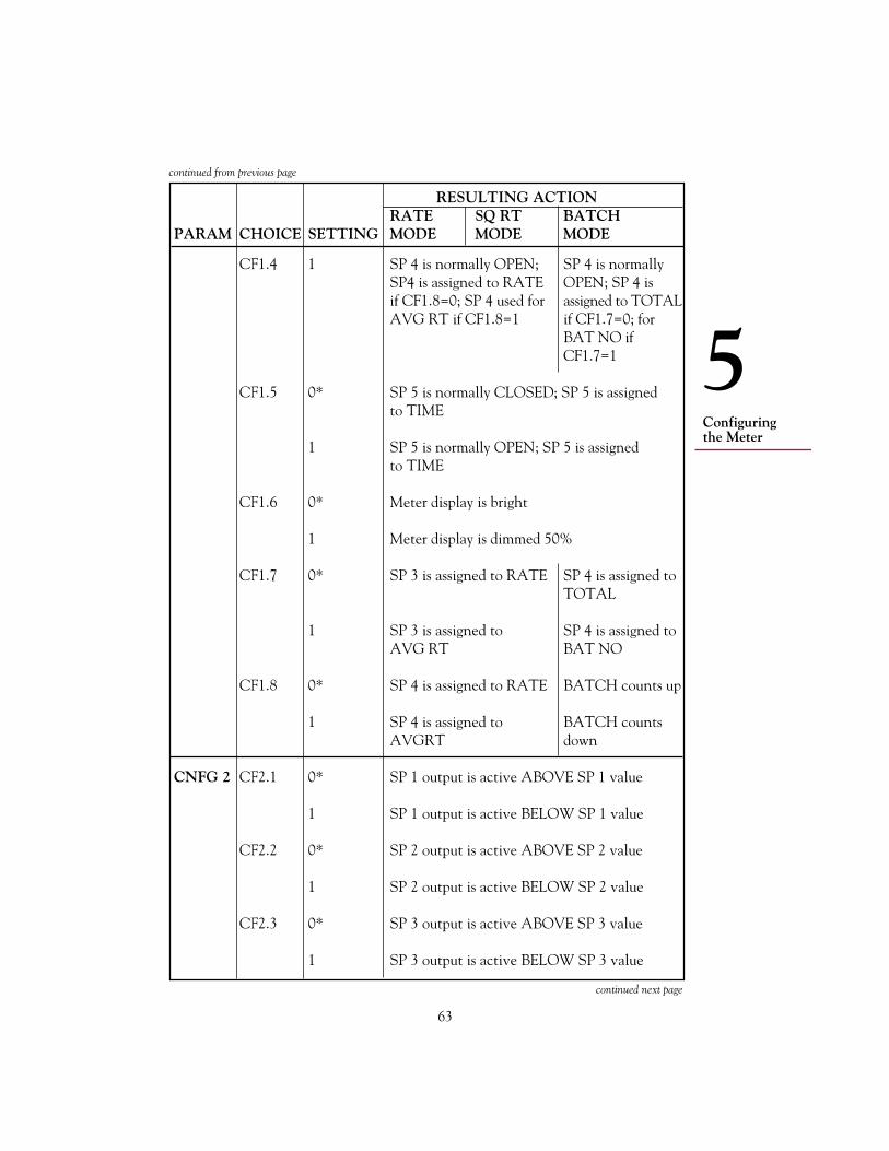
63
Configuringthe Meter
5
RESULTING ACTIONRATE SQ RT BATCH
PARAM CHOICE SETTING MODE MODE MODE
CF1.4 1 SP 4 is normally OPEN; SP 4 is normallySP4 is assigned to RATE OPEN; SP 4 isif CF1.8=0; SP 4 used for assigned to TOTALAVG RT if CF1.8=1 if CF1.7=0; for
BAT NO ifCF1.7=1
CF1.5 0* SP 5 is normally CLOSED; SP 5 is assignedto TIME
1 SP 5 is normally OPEN; SP 5 is assignedto TIME
CF1.6 0* Meter display is bright
1 Meter display is dimmed 50%
CF1.7 0* SP 3 is assigned to RATE SP 4 is assigned toTOTAL
1 SP 3 is assigned to SP 4 is assigned toAVG RT BAT NO
CF1.8 0* SP 4 is assigned to RATE BATCH counts up
1 SP 4 is assigned to BATCH countsAVGRT down
CNFG 2 CF2.1 0* SP 1 output is active ABOVE SP 1 value
1 SP 1 output is active BELOW SP 1 value
CF2.2 0* SP 2 output is active ABOVE SP 2 value
1 SP 2 output is active BELOW SP 2 value
CF2.3 0* SP 3 output is active ABOVE SP 3 value
1 SP 3 output is active BELOW SP 3 value
continued from previous page
continued next page

64
Configuringthe Meter
5
RESULTING ACTIONRATE SQ RT BATCH
PARAM CHOICE SETTING MODE MODE MODE
CF2.4 0* SP 4 output is active ABOVE SP 4 value
1 SP 4 output is active BELOW SP 4 value
CF2.5 0* SP 5 output is active ABOVE SP 5 value
1 SP 5 output is active BELOW SP 5 value
CF2.6 0* SP 3 action is not delayed RESET action isnormal (manualby the front-panelRESET buttonor externalP2-2 reset)
1 SP 3 action is delayed for At SP 3 value,4 alarm readings meter
Autoresetsto 0; or at 0, meterAutoresetsto SP3 value
CF2.7 0* SP 4 action is not delayed BAT NO counts up
1 SP 4 action is delayed for BAT NO counts4 alarm readings down from SP 4
value if CF1.7=1
CF2.8 0 Meter is set for 60 Hz power
(See 1 Meter is set for 50 Hz powerAppendixJ forfactorysetting)
continued from previous page
continued next page

65
Configuringthe Meter
5
RESULTING ACTIONRATE SQ RT BATCH
PARAM CHOICE SETTING MODE MODE MODE
CNFG 3 CF3.1 0 Analog output = disabled(AnalogOutput) 1* RATE is sent BATCH count is
sent2 AVG RT is sent BAT NO is sent
3 TOTAL is sent
4 Output is ramped (See Appendix K for RampSpecs)
CF3.2 0 BCD output = disabled(BCDOutput) 1* RATE is sent BATCH count is
sent
2 AVG RT is sent BAT NO is sent
3 TOTAL is sent
4 TIME is sent
CF3.3 0* SP 1 output is normal (unlatched)(SP 1)
1 SP 1 output is latched
2 SP 1 output is pulsed with 70 to 140 msduration unless SP 1 is the designated setpointin the AL TI parameter, in which case pulseduration is set by AL TI
CF3.4 0* SP 2 output is normal (unlatched)(SP 2)
1 SP 2 output is latched
2 SP 2 output is pulsed with 70 to 140 msduration unless SP 2 is the designated setpointin the AL TI parameter, in which case pulseduration is set by AL TI
continued next page
continued from previous page
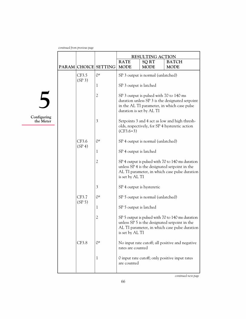
66
Configuringthe Meter
5
RESULTING ACTIONRATE SQ RT BATCH
PARAM CHOICE SETTING MODE MODE MODE
CF3.5 0* SP 3 output is normal (unlatched)(SP 3)
1 SP 3 output is latched
2 SP 3 output is pulsed with 70 to 140 msduration unless SP 3 is the designated setpointin the AL TI parameter, in which case pulseduration is set by AL TI
3 Setpoints 3 and 4 act as low and high thresh-olds, respectively, for SP 4 hysteretic action(CF3.6=3)
CF3.6 0* SP 4 output is normal (unlatched)(SP 4)
1 SP 4 output is latched
2 SP 4 output is pulsed with 70 to 140 ms durationunless SP 4 is the designated setpoint in theAL TI parameter, in which case pulse durationis set by AL TI
3 SP 4 output is hysteretic
CF3.7 0* SP 5 output is normal (unlatched)(SP 5)
1 SP 5 output is latched
2 SP 5 output is pulsed with 70 to 140 ms durationunless SP 5 is the designated setpoint in theAL TI parameter, in which case pulse durationis set by AL TI
CF3.8 0* No input rate cutoff; all positive and negativerates are counted
1 0 input rate cutoff; only positive input ratesare counted
continued next page
continued from previous page

67
Configuringthe Meter
5
RESULTING ACTIONRATE SQ RT BATCH
PARAM CHOICE SETTING MODE MODE MODE
2 100 Hz 5% of displayinput rate full scalecutoff; only cutoff; onlyinput rates input rates>100 Hz reading ≥5%are of display fullcounted scale are
counted
3 300 Hz 10% ofinput rate display fullcutoff; only scale cutoff;input rates only input>300 Hz rates readingare 10% ofcounted display full
scale arecounted
CF3.9 0 Meter waits up to 11 s forfinal pulse beforecomputing RATE
1* Meter waits up to 2 s forfinal pulse beforecomputing RATE
2 Meter waits up to 0.5 s forfinal pulse beforecomputing RATE
3 Meter waits up to 0.15 s forfinal pulse beforecomputing RATE
continued from previous page
continued next page

68
Configuringthe Meter
5
RESULTING ACTIONRATE SQ RT BATCH
PARAM CHOICE SETTING MODE MODE MODE
CNFG 4 CF4.1 0* External RESET A (P2-3) triggered on pulse edge
1 External RESET A (P2-3) triggered on pulse level
CF4.2 0 Calibrated Analog Output = Voltage
1* Calibrated Analog Output = Current
CF4.3 0* Display HOLD (P2-16) = disabled
1 Display HOLD (P2-16) = enabled
CF4.4 0* Print Request (P2-16) = disabled
1 Print Request (P2-16) via V01communications = enabled (Appendix G)
CF4.5 0* 10-ms output pulse on Pulse output onP2-15 at the end of each P2-15 is low whenRATE measurement input rate is cut off,
high if rate is notcut off
1 Output pulse on P2-15 is low for 100 ± 40 ms:repeat rate is configured by SER TI (Serial Time)
CF4.6 0* BCD binary address decimal point is rightjustified (See Appendix E)
1 BCD binary address decimal point is leftjustified (See Appendix E)
CF4.7 0* Front-panel RESET = enabled
1 Front-panel RESET = disabled
continued from previous page
continued next page

69
Configuringthe Meter
5
RESULTING ACTIONRATE SQ RT BATCH
PARAM CHOICE SETTING MODE MODE MODE
CF4.8 0* Automatic Scale and Front-panelOffset = disabled STOP =disabled(See below)
1 Automatic Scale and Front-panelOffset = enabled. (Sets STOP =enabledthe scale factors ofIN.SC.OF and RTE SCto 1.00000, and theoffset factors of IN.SC.OFand RTE OF to 0.00000
continued from previous page
5.4.3 AVG.CNF (Rate, Sq Rt)
AVG.CNF (Running Average Configuration) selects the type andamount of average rate filtering for Rate and Sq Rt Modes. Followthe steps 1 through 4 in Section 5.2 to configure this parameter.
There are 5 choices. The first four, AVG.1 through AVG.4, setthe number of values averaged into AVG RT.
Table 5-4 shows you the settings of the first 4 choices. Factorypreset settings are asterisked and correspond to 256 total values inthe average.

70
Configuringthe Meter
5
TABLE 5-4. AVG RT VALUES
TOTAL CHOICEVALUESIN AVERAGE AVG.1 AVG.2 AVG.3 AVG.4
1 0 0 0 02 1 0 0 04 0 1 0 08 1 1 0 016 0 0 1 032 1 0 1 064 0 1 1 0128 1 1 1 0256 0* 0* 0* 1*512 1 0 0 11024 0 1 0 12048 1 1 0 14096 0 0 1 18192 1 0 1 116384 0 1 1 132768 1 1 1 1
The fifth choice, AVG.5, selects the filter type, adaptive or fixed.AVG.5=0 selects the ABC* (Adaptive Bandwidth Control) filterwhich keeps track of the signal history and detects systematicchanges. When changes occur, it repeatedly reduces the number ofvalues in the average. When the input rate is changing slowly,ABC repeatedly extends the number of readings averaged, so thatexcellent noise reduction is obtained.
AVG.5=1 selects the fixed-number-average filter, similar to thetime constant of an analog first-order filter. Although much slowerthan the ABC filter, this fixed filter does give the familiar single-exponential response to step and ramp input changes. The AVG.5factory preset value is 0.
5.4.4 IN.SC.OF (Rate, Sq Rt, Batch)
IN.SC.OF (Input Scale and Offset) is used to calibrate analoginput, using the calibration data on the back of the Isolated AnalogInput Board. (The Isolated Pulse Input Board may be used in asituation where it also requires calibration, but this is rare.)
* Patent applied for.

71
Configuringthe Meter
5
IN.SC.OF can also be used to calibrate both the Isolated AnalogInput Board and the incoming signal.
See Appendix C for more information and calibration instructions.
5.4.5 OT.SC.OF (Rate, Sq Rt, Batch)
OT.SC.OF (Output Scale and Offset) converts the meter readingto the desired analog output signal. It takes two data points–eachbased on an actual display reading–and uses them to produce thecorresponding analog output values. Analog output can be eitherdirect acting or reverse acting.
Internally, the meter takes the two data points and calculates thescale (the slope of the line defined by the two points) and theoffset (the output when the display reading is 0). Then it auto-matically converts display readings according to the calculatedvalues using the following equation:
Output = (Display reading SCale) + OFfset
You must know the desired output that the display readingscorrespond to.
OT.SC.OF can also be used to set the slope of an analog outputramping function. (See Appendix K.)
Use Table 5-5 to configure OT.SC.OF. Read from left to rightstarting with the Press command. The first line reads, “Press theMENU button repeatedly until the display reads OT.SC.OF.”
TABLE 5-5. OT.SC.OF CONFIGURATION
UNTILTHE THEDISPLAY DISPLAY
STEP PRESS: SHOWS: SHOWS: COMMENTS
1 MENU OT.SC.OF You are now ready torepeatedly configure OT.SC.OF
2 /STOP READ 1
continued next page

72
Configuringthe Meter
5
UNTILTHE THEDISPLAY DISPLAY
STEP PRESS: SHOWS: SHOWS: COMMENTS
3 /STOP 000000. Now enter the display reading of the“low” output signal:Press the /DISPLAY button repeat-edly to set the flashing digit; press the /STOP button to move to new digits
4 MENU OUTPT 1
5 /STOP 000000. Enter the output value that youwould like the READ 1 tocorrespond to:Press the /DISPLAY button repeatedly to set the flashing digit; press the /STOP button to move to new digitsWhen you press the MENU buttonnext, the first data point will be saved
6 MENU READ 2
7 /STOP 000000. Enter the display reading ofthe “high” output signal:Press the /DISPLAY button repeatedly to set the flashing digit; press the /STOP button to move to new digits
8 MENU OUTPT 2
9 /STOP 000000. Enter the output value thatyou would like the READ 2 tocorrespond to:Press the /DISPLAY button repeatedly to set the flashing digit; press the /STOP button to move to new digitsWhen you press the MENUbutton next, the first datapoint will be saved
10 MENU RTE DP You have successfullycalculated OT.SC.OF
Table 5-5 (cont’d)

73
Configuringthe Meter
5
NOTE: If you receive an error message just after pressing theMENU button for the last time, note the message and seeAppendix H.
Factory preset settings pertain to current output and are as follows:
READ 1 = 0 OUT 1 = 4 mAREAD 2 = 10000 OUT 2 = 20 mA
5.4.6 RTE DP (Rate, Sq Rt)
RTE DP (Rate Decimal Point) is used to select the resolution ofthe RATE display. The factory preset value is RRRRRR.
Press the MENU button repeatedly until the display reads RTE DP.Press the /STOP button to display the current decimal pointposition. The display will show RRRRRR and the decimal pointwill flash. Change the position of the decimal point by pressingthe /DISPLAY button repeatedly, then press the MENU buttonto store the desired position.
The settings for this parameter are interdependent with settings forsetpoints and those for offsets (IN.SC.OF and RTE OF).
If you receive an ERR 02 message, the placement of your decimalpoint has left insufficient display places to accommodate one of thesetpoints. The meter sets that setpoint to the maximum valuepossible with the restrictive decimal point position and continues.
If you receive an ERR O1 message, the placement of the decimalpoint has left insufficient display places to accommodate a pro-grammed offset value. The meter cannot continue. You mustchoose a decimal point setting that allows display of all offset digits.
5.4.7 RTE OF (Rate, Sq Rt)
RTE OF (Rate Offset) allows you to directly enter a known RATEoffset. It does not affect TOTAL readings in any way. The factorypreset is 0.
Please note that RTE OF is entered in display units, the units ofmeasure corresponding to the RATE display reading. Factorypreset display units are Hertz (Hz), pulses per second.
Press the MENU button repeatedly until the display shows RTE OF.

74
Configuringthe Meter
5
Press the /STOP button; the display will show the current offset;the first digit will flash. Press the /DISPLAY button to set theflashing digit, and advance to the next one by pressing the /STOPbutton. When the desired number has been entered, press theMENU button. The meter will store RTE OF and advance to thenext parameter.
The setting for this parameter is interdependent with that for RTE DP.
5.4.8 RTE SC (Rate, Sq Rt)
RTE SC (RATE Scale) allows you to directly enter a known RATEscale. It is used to convert input units to other display units. Itdoes not affect TOTAL readings in any way. The factory presetoperator is MULTIP and the factory preset value is 000001.
Press the MENU button repeatedly until the display reads RTE SC.Press the /STOP button; the display will flash the current scale,either DIVIDE or MULTIP. Press the /DISPLAY button totoggle the display to the correct operator, then press the /STOP button. The display will show the current scale factor in6 digits. Set each digit by repeated pressing of the /DISPLAYbutton, and move to new digits and the decimal point by pressingthe /STOP button. (You may move the decimal point to anyposition here; it is not interdependent with other parametersettings.)
Press the MENU button to store RTE SC and advance to the nextparameter
5.4.9 TOT DP (Rate, Sq Rt, Batch)
TOT DP (Total Decimal Point) allows you to select the resolutionof the TOTAL display. The factory preset is TTTTTT.
Press the MENU button repeatedly until the display reads TOTDP, then press the /STOP button. The display will showTTTTTT and the current decimal point will flash. Change theposition of the decimal point by pressing the /DISPLAY buttonrepeatedly, then press the MENU button to store the desiredposition.
The setting for this parameter is interdependent with that for TOT OF.
If you receive an ERR 02 message, the placement of your decimalpoint has left insufficient display places to accommodate one of the

75
Configuringthe Meter
5
setpoints. The meter adjusts the decimal point and continues afterdisplaying an ERR O2.
If you receive an ERR O1 message, the placement of the decimalpoint has left insufficient display places to accommodate the pro-grammed TOT OF value. The meter cannot continue. You mustchoose a decimal point setting that allows display of all offset digits.Press the /STOP button, reconfigure the decimal point position,then press the MENU button to store the desired position. Themeter will advance to the next parameter.
5.4.10 TOT OF (Rate, Sq Rt, Batch)
TOT OF (Total Offset) allows you to offset the displayed TOTALvalue. This value is loaded onto the TOTAL display when aRESET-C is initiated in Batch Mode, or a RESET-A is initiated inRate or Sq Rt Modes. The factory preset value is 0. The maximumallowable offset is 500.
Please note that TOT OF is entered in display units–the units ofmeasure corresponding to the TOTAL display reading. Factorypreset display units are pulses or counts.
Press the MENU button repeatedly until the display showsTOT OF. Press the /STOP button; the display will show thecurrent offset; the first digit will flash. Press the /DISPLAYbutton to set the flashing digit, and advance to the next one bypressing the /STOP button. When the desired number has beenentered, press the MENU button. The meter will store TOT OFand advance to the next parameter.
The setting for this parameter is interdependent with that for TOT DP.
5.4.11 TOT SC (Rate, Sq Rt, Batch)
TOT SC (TOTAL Scale) is used to convert TOTAL to units otherthan those of the input. It does not affect RATE readings in any way.The factory preset is MULTIP and the factory preset value is 000001.
Press the MENU button repeatedly until the display reads TOT SC.Press the /STOP button; the display will flash the current scale,either DIVIDE or MULTIP. Press the /DISPLAY button to togglethe display to the correct operator, then press the /STOP button.The display will show the current scale factor in 6 digits. Set each

76
Configuringthe Meter
5
digit by repeated pressing the /DISPLAY button, and move to newdigits and the decimal point by pressing the /STOP button. (Youmay move the decimal point to any position here; it is not interdepen-dent with other parameter settings.)
Press the MENU button to store TOT SC and advance to the nextparameter.
5.4.12 AL TI (Rate, Sq Rt, Batch)
AL TI (Alarm Time) defines the pulse duration in seconds of one (andonly one) setpoint that is set to Pulsed in choices CF3.3 throughCF3.7. (Any pulsed setpoint that is not the designated setpoint asdefined by AL TI, defaults to a pulse duration of 70 to 140 ms.) Thefactory preset setpoint is 0 and the factory preset time is 00:00.
When the setpoint is set to 0, AL TI is used to ramp the analogoutput function. (Configuration choice CF3.1 must be set to 4.)The pulse duration becomes the ramp time–the time it takes tocompletely open a closed valve. (See Appendix K.)
Press the MENU button repeatedly until the display shows AL TI,then press the /STOP button. The display will show the desig-nated setpoint (which should flash) followed by an equal sign andthe corresponding pulse duration. Press the /DISPLAY buttonrepeatedly to set the setpoint, then press the /STOP button andthe /DISPLAY button to advance to, and set, the digits of thepulse duration. Pulse duration cannot exceed 99.99 s. Press theMENU button to store AL TI and advance to the next parameter.
5.4.13 GATE T (Rate)
GATE T (Gate Time) refers to the length of time in which themeter accepts input pulses for a single rate calculation. The longerGATE T, the better the resolution. (GATE T, is not used for therate calculation; a similar, but much more accurate method calledMeasurement Time is used.)
There are 5 choices: (approximately) 0.03 s, 0.10 s, 0.30 s, 1.00 s,and 3.00s. The factory preset value is 0.30 s.
Press the MENU button repeatedly until the display reads GATE T.Press the /STOP button. The display will flash the currentsetting. Press / DISPLAY repeatedly to sequence through thepossible choices, then press the MENU button to store the desiredGATE T and advance to the next parameter.
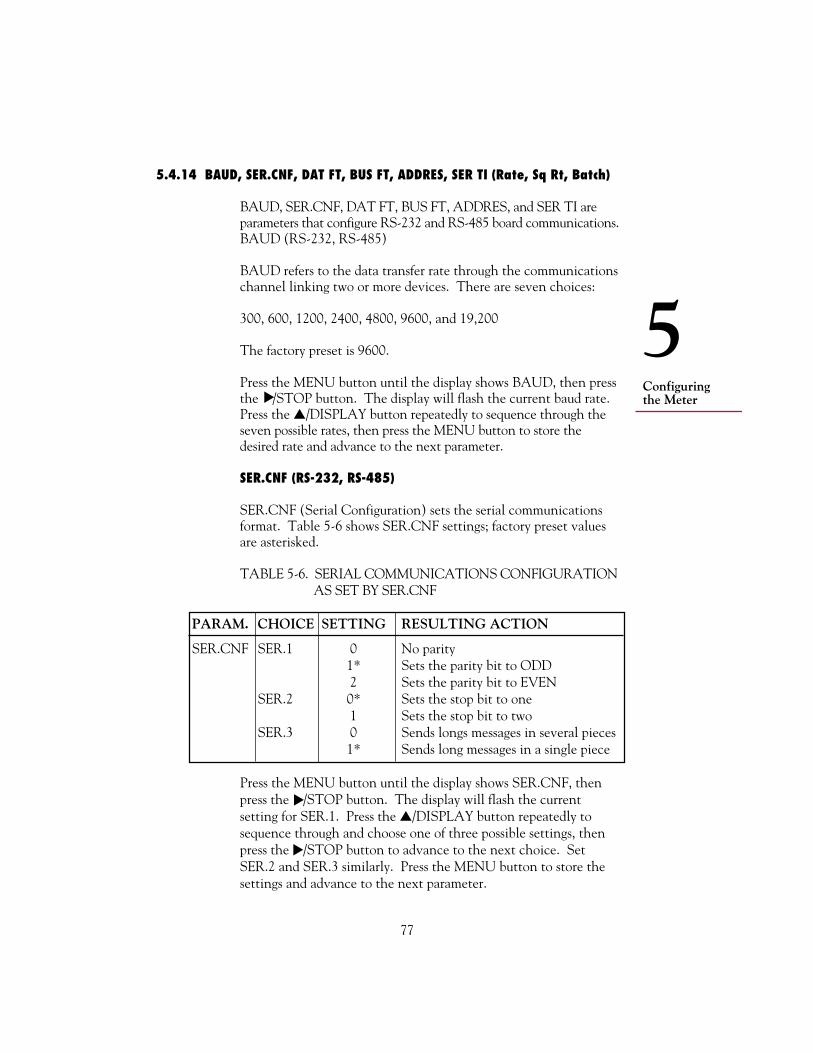
77
Configuringthe Meter
5
5.4.14 BAUD, SER.CNF, DAT FT, BUS FT, ADDRES, SER TI (Rate, Sq Rt, Batch)
BAUD, SER.CNF, DAT FT, BUS FT, ADDRES, and SER TI areparameters that configure RS-232 and RS-485 board communications.BAUD (RS-232, RS-485)
BAUD refers to the data transfer rate through the communicationschannel linking two or more devices. There are seven choices:
300, 600, 1200, 2400, 4800, 9600, and 19,200
The factory preset is 9600.
Press the MENU button until the display shows BAUD, then pressthe /STOP button. The display will flash the current baud rate.Press the /DISPLAY button repeatedly to sequence through theseven possible rates, then press the MENU button to store thedesired rate and advance to the next parameter.
SER.CNF (RS-232, RS-485)
SER.CNF (Serial Configuration) sets the serial communicationsformat. Table 5-6 shows SER.CNF settings; factory preset valuesare asterisked.
TABLE 5-6. SERIAL COMMUNICATIONS CONFIGURATION AS SET BY SER.CNF
PARAM. CHOICE SETTING RESULTING ACTION
SER.CNF SER.1 0 No parity1* Sets the parity bit to ODD2 Sets the parity bit to EVEN
SER.2 0* Sets the stop bit to one1 Sets the stop bit to two
SER.3 0 Sends longs messages in several pieces1* Sends long messages in a single piece
Press the MENU button until the display shows SER.CNF, thenpress the /STOP button. The display will flash the currentsetting for SER.1. Press the /DISPLAY button repeatedly tosequence through and choose one of three possible settings, thenpress the /STOP button to advance to the next choice. SetSER.2 and SER.3 similarly. Press the MENU button to store thesettings and advance to the next parameter.

78
Configuringthe Meter
5
DAT FT (RS-232, RS-485)
DAT FT (Data Format) controls the message response to Point-to-Point Continuous Transmission and V01 commands. It determineswhether or not certain characters or values are sent along with thebasic message. Factory preset values are asterisked.
TABLE 5-7. MESSAGE RESPONSE AS SET BY DAT FT
RESULTING ACTIONDISABLES RATE SQ. RT BATCH
PARAM CHOICE SET’G /ENABLES MODE MODE MODE
DAT FT DAT.1 0 Disables Addition of alarm status character to1* Enables the message
DAT.2 0 Disables Addition of Addition of1* Enables RATE value BATCH count
to the message to the message
DAT.3 0 Disables Addition of Addition of1* Enables AVG RT value BAT NO
to the message to the message
DAT.4 0 Disables Addition of TOTAL value to the1* Enables message
DAT.5 0 Disables Addition of TIME to the message1* Enables
DAT.6 0 Disables Addition of Addition of1* Enables RATE unit BATCH count
of measurement unit ofmeasurement
DAT.7 0 Disables Addition of Addition of1* Enables AVG RT unit BAT NO unit
of measurement of measurement
DAT.8 0 Disables Addition of TOTAL unit of1* Enables measurement
Press the MENU button until the display shows DAT FT, then press the /STOP button. The display will flash the current setting for DAT.1.Press the /DISPLAY button one or two times to set the choice to 0 or1, then press the /STOP button to advance to the next choice. Setchoices DAT.2 through DAT.8 similarly. Press the MENU button tostore the settings and advance to the next parameter.

79
Configuringthe Meter
5
BUS FT (RS-232, RS-485)
BUS FT (Bus Format) configures the serial communications format.Table 5-8 shows BUS FT settings; factory preset values are asterisked.
TABLE 5-8. BUS CONFIGURATION AS SET BY BUS FT
RESULTING ACTIONRATE SQ RT BATCH
PARAM CHOICE SETTING MODE MODE MODE
BUS FT BUS.1 0* Does not add a check sum to the message1 Adds a check sum to the message
BUS.2 0 Does not add a line feed <LF> to the message1* Adds a line feed <LF> to the message
BUS.3 0* Does not add a command ECHO in frontof the message
1 Adds a command ECHO in front of themessage
BUS.4 0* Sets the meter to Point-to-Point Mode1 Sets the meter to Multipoint Mode
BUS.5 0* Sets Point-to-Point Mode to Continuous1 Sets Point-to-Point Mode to Command
BUS.6 0* In Point-to-Point Mode, sets RTS handshaketo Message
1 In Point-to-Point Mode, sets RTS handshaketo Character
BUS.7 0* Sets the meter for RS-232 communications1 Sets the meter for RS-485 communications
BUS.8 0* Separator for DAT FT choices 1, 2, 3, and 4 isthe SPACE
1 Separator for DAT FT choices 1, 2, 3, and 4 isthe <CR> (Carriage Return)
Press the MENU button until the display shows BUS FT, then press the /STOP button. The display will flash the current setting for BUS.1.Press the /DISPLAY button one or two times to set the choice to 0 or 1,then press the /STOP button to advance to the next choice. Setchoices BUS.2 through BUS.8 similarly. Press the MENU button to storethe settings and advance to the next parameter.

80
Configuringthe Meter
5
ADDRES (RS-232, RS-485)
ADDRES (Address) specifies the meter ID. It is important in RS-485communications (when multiple meters share the same bus) that eachmeter have a different address. The address can be from 0 to 199.
Press the MENU button repeatedly until the display showsADDRES, then press the /STOP button. The meter will showthe current address. Press the /DISPLAY button repeatedly to seteach digit, and the /STOP button to advance to the next digit.Press the MENU button to store the desired address and advance tothe next parameter.
SER TI (RS-232, RS-485)
SER TI (Serial Time) specifies the interval of time in secondsbetween consecutive transmissions in Point-to Point or ContinuousMode. The SER TI value can be from 1 to 59999 s. A zero settingsends transmissions as fast as possible. The factory preset value is 1 s.
Press the MENU button repeatedly until the display shows SER TI,then press the /STOP button. The display will show the currentSER TI value with the first digit flashing. Set each digit by repeatedpressing of the /DISPLAY button and advance to the next digit bypressing the /STOP button. Press the MENU button to store thedesired SET TI and advance to the next parameter.
5.4.15 SET TI (Rate, Sq Rt, Batch)
SET TI is the time in HH:MM:SS format that is loaded on the TIMEdisplay when the front-panel RESET button is pressed.
The clock can run on two cycles, a 24-hour cycle and a 99-hourcycle. If you set HH less than 24, it runs on the 24-hour cycle. Ifyou set HH greater than 24 and less than or equal to 99, the clockruns on the 99-hour cycle. The factory preset value is 12:00:00; theclock will run on the 24-hour cycle.
Press the MENU button until the display shows SET TI, then pressthe /STOP button. The display will show the current settingwith the first digit flashing. Set each digit by pressing the/DISPLAY button repeatedly, and go on to new digits by pressingthe /STOP button. Press the MENU button to store the desiredtime and advance to the next parameter.

81
Configuringthe Meter
5
5.4.16 BAT DP (Batch)
BAT DP (Batch Decimal Point) sets the BATCH decimal pointposition. The factory preset value is RRRRRR.
Press the MENU button repeatedly until the display showsBAT DP, then press the /STOP button. The display will showBBBBBB and the current decimal point will flash. Change theposition of the decimal point by pressing the /DISPLAY buttonrepeatedly, then press the MENU button to store the desiredposition.
If you receive an error message, press the /STOP button, reconfigurethe decimal point position, then press the MENU button to store thedesired position.
NOTE: The meter will show an error message, STORED thenB LOAD. You will then need to press the RESET button one timeto go back to BAT DP and reposition the decimal point.
5.4.17 B LOAD (Batch)
B LOAD (Batch Load) is the loading value of the BATCH count(unit count). This value is loaded onto the display when the frontpanel RESET button is pressed while BATCH is displayed.
It can be used to reset the BATCH count to a positive numberwhen operation has been halted and you want to load a specificBATCH value so that the operation will pick up exactly where itleft off. In this case, you would configure the B LOAD value justbefore resuming operation; immediately after resuming operation, aRESET-B would load the desired BATCH value on the display.
The factory preset value is 0.
Press the MENU button repeatedly until the display showsB LOAD, then press the /STOP button. The display will showthe current B LOAD in 6 digits with the first digit flashing. Pressthe /DISPLAY button repeatedly to set each digit, then press the /STOP button to advance to next digit. Press the MENU buttonto store the desired B LOAD and advance to the next parameter.
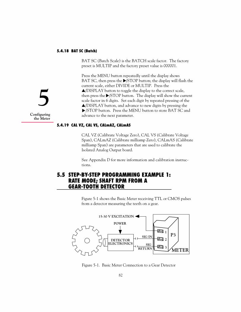
82
Configuringthe Meter
5
5.4.18 BAT SC (Batch)
BAT SC (Batch Scale) is the BATCH scale factor. The factorypreset is MULTIP and the factory preset value is 000001.
Press the MENU button repeatedly until the display showsBAT SC, then press the /STOP button; the display will flash thecurrent scale, either DIVIDE or MULTIP. Press the/DISPLAY button to toggle the display to the correct scale,then press the /STOP button. The display will show the currentscale factor in 6 digits. Set each digit by repeated pressing of the/DISPLAY button, and advance to new digits by pressing the /STOP button. Press the MENU button to store BAT SC andadvance to the next parameter.
5.4.19 CAL VZ, CAL VS, CALmAZ, CALmAS
CAL VZ (Calibrate Voltage Zero), CAL VS (Calibrate VoltageSpan), CALmAZ (Calibrate milliamp Zero), CALmAS (Calibratemilliamp Span) are parameters that are used to calibrate theIsolated Analog Output board.
See Appendix D for more information and calibration instruc-tions.
5.5 STEP-BY-STEP PROGRAMMING EXAMPLE 1: RATE MODE; SHAFT RPM FROM A GEAR-TOOTH DETECTOR
Figure 5-1 shows the Basic Meter receiving TTL or CMOS pulsesfrom a detector measuring the teeth on a gear.
Figure 5-1. Basic Meter Connection to a Gear Detector
METER
P31
2
3
POWER
15-30 V EXCITATION
DETECTORELECTRONICS
SIG IN
SIG RETURN

83
Configuringthe Meter
5
5.5.1 DETERMINING THE RATE SCALE (RTE SC)
TOTAL is not used in a shaft-speed application, no digital commu-nications are used, and the example has no Analog Output.Therefore, many associated parameters will not be used.
The first step in this application is to decide what units you wantthe meter to display. Let’s say that you want the meter to displayrevolutions per minute.
Rotation of the shaft produces X revolutions per minute (RPM) timesN gear teeth to produce RPM*N pulses per minute. The meter’sfactory preset RATE units are Hertz (Hz), pulses per second. There-fore, the display would show RPM*N/60. To get a reading in RPM:
RTE SC = 60/N
If N = 12 (12 teeth on the gear),
RTE SC = 60/12 = 5.00000
5.5.2 CONFIGURING THE METER
This section shows you how to configure the meter for the firstexample. There are only a limited number of parameters that needto be changed from factory preset values, but all parameters thataffect RATE up to RTE SC will be covered in case the correspond-ing preset values have been changed through experimentation orprevious configuration.
1. Set all Lockouts to 0 (Section 5.3.2). All possible parameterswill be displayed in sequence when you repeatedly press theMENU button.
2. Set the MODE to Rate (Section 5.4.1). The meter will reset andrevert to Run Mode when you press the MENU button to storethe selected MODE.
3. Press the MENU button five times to advance past MODE toCNFG 1. Set all CNFG parameters equal to 0 (Section 5.4.2).
4. Make sure IN.SC.OF is programmed to set the scale to 1 and theoffset to 0 (Appendix C). Input the following values:

84
Configuringthe Meter
5
INPUT 1 = 0READ 1 = 0INPUT 2 = 100000READ 2 = 100000
5. Set RTE DP to RRRRR.R (Section 5.4.6). This gives 0.1 RPMresolution.
Ignore any ERR 02 message. This indicates a setpoint overflowthat can easily be corrected when or if you set setpoints later.
6. Set RTE OF equal to 0 (Section 5.4.7).
7. Set RTE SC to MULTIP and a scale of 5 as calculated above(Section 5.4.8).
This concludes RATE programming. All other parameters (forTOTALs, Alarm Time, Gate Time, Serial Communications, etc.)have no effect on RATE measurements.
See Section 4.9.2 and Section 5.4.2 to program setpoints.
See Section 5.6 for adding TOTALs to a different example.
If you want the clock to run in the background, set SET TI (Sec-tion 5.4.15). To start TIME, press the /DISPLAY button untilyou see TIME and the reading in HH:MM:SS is displayed, thenpress the RESET button.
After all parameters have been set to required values, you may wantto set the corresponding Lockouts equal to 1 so that your settingscannot be changed.
Assuming the meter has been connected to the flowmeter and isoperating correctly in Rate Mode, it will display the RATE in GPMwhen the /DISPLAY button is pressed.
If the shaft in this example drove a mill roller, conveyor belt,vehicle wheel or other rotary-to-linear device, TOTAL could beused to measure distance or amount of product passed.

85
Configuringthe Meter
5
Figure 5-2. Basic Meter Connection to a Shaft Position Detector
To demonstrate the meter’s scale and offset capability, set theRATE display to GPM (gallons per minute), but the TOTAL toCubic Feet. This can be done because the decimal point location,scale factor and offset settings for RATE are completely indepen-dent of those for TOTAL.
An external signal (e.g., a limit switch closure or timing pulse) isconnected to P2-3 (RESET-A) and is used to reset the TOTAL.
5.6 STEP-BY-STEP PROGRAMMING EXAMPLE 2:LINEAR FLOW; ADDING TOTAL TO RATE WITHEXCITATION FROM THE BASIC METER
In this example, the pulse source is a 100-pulse-per-gallon linearflowmeter (i.e., a turbine meter) which is powered by the unregu-lated 16 V excitation from the Basic Meter. See Figure 5-2.
METER
P31
2
3
SENSORAMP
EXCITATION
SIG IN
SIG RETURN
MAGPICKUP
TURBINE
FLOW
5.6.1 DETERMINING THE RATE DECIMAL POINT (RTE DP) AND RATE SCALE (RTE SC)
Once again the pulse source does not have an offset, so the onlyRATE parameters to be set are the decimal point (RTE DP) andscale factor (RTE SC).
Selecting the RTE DP position as RRRR.RR gives a possible fullscale reading of 9999.99 GPM, or (dividing by 60) 166.67 gal/s.With 100 pulses per gallon, the maximum pulse rate would be16.67 kHz.

86
Configuringthe Meter
5
Without offset,
RTE SC =
= 9999.99 = 0.60000 16667
This is an easy MULTIP scale factor.
5.6.2 DETERMINING THE TOTAL DECIMAL POINT (TOT DP) AND TOTAL SCALE (TOT SC)
Selecting the decimal point as TTTTT.T gives a full-tank value of99,999.9 cubic feet, where each cubic foot = 7.481 gallons.
The number of pulses N received for 1 cubic foot is
N = 1.0 * 7.481 * 100 = 748.1
RTE SC =
RTE SC =
This yields a DIVIDE scale of 748.1.
5.6.3 CONFIGURING THE METER
This section shows you how to configure the meter for the secondexample. There are only a limited number of parameters that need tobe changed from the factory preset values, but all parameters up toTOT SC will be covered in case the corresponding factory presets havebeen changed through experimentation or previous configuration.
1. Set all Lockouts equal to 0 (Section 5.3.2). All possible param- eters will be displayed in sequence when you repeatedly press the
MENU button.
2. Set the MODE until you see Rate on the display (Section 5.4.1).The meter will reset and revert to Run Mode when you press theMENU button to store the selected MODE.
3. Press the MENU button five times to advance past MODE toCNFG 1. Set all CNFG parameters to 0 (Section 5.4.2).
Desired ReadingActual Input Reading
Desired ReadingActual Input Reading
1748.1
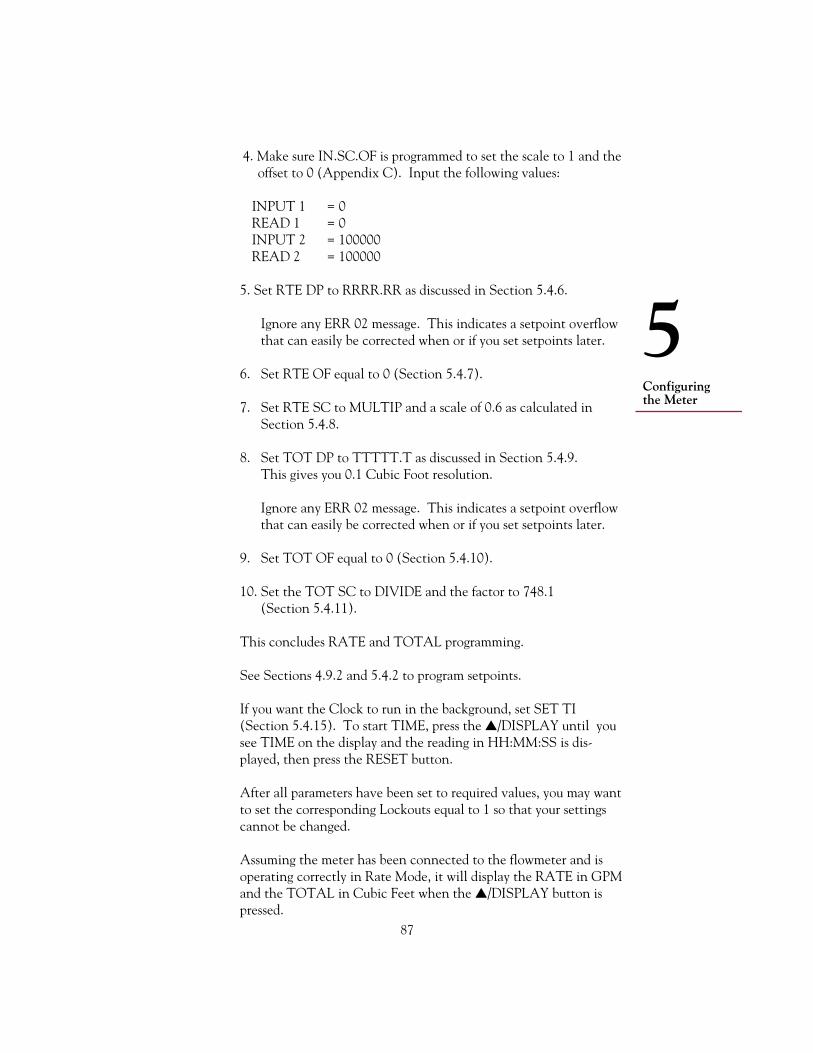
87
Configuringthe Meter
5
4. Make sure IN.SC.OF is programmed to set the scale to 1 and theoffset to 0 (Appendix C). Input the following values:
INPUT 1 = 0READ 1 = 0INPUT 2 = 100000READ 2 = 100000
5. Set RTE DP to RRRR.RR as discussed in Section 5.4.6.
Ignore any ERR 02 message. This indicates a setpoint overflowthat can easily be corrected when or if you set setpoints later.
6. Set RTE OF equal to 0 (Section 5.4.7).
7. Set RTE SC to MULTIP and a scale of 0.6 as calculated inSection 5.4.8.
8. Set TOT DP to TTTTT.T as discussed in Section 5.4.9.This gives you 0.1 Cubic Foot resolution.
Ignore any ERR 02 message. This indicates a setpoint overflowthat can easily be corrected when or if you set setpoints later.
9. Set TOT OF equal to 0 (Section 5.4.10).
10. Set the TOT SC to DIVIDE and the factor to 748.1(Section 5.4.11).
This concludes RATE and TOTAL programming.
See Sections 4.9.2 and 5.4.2 to program setpoints.
If you want the Clock to run in the background, set SET TI(Section 5.4.15). To start TIME, press the /DISPLAY until yousee TIME on the display and the reading in HH:MM:SS is dis-played, then press the RESET button.
After all parameters have been set to required values, you may wantto set the corresponding Lockouts equal to 1 so that your settingscannot be changed.
Assuming the meter has been connected to the flowmeter and isoperating correctly in Rate Mode, it will display the RATE in GPMand the TOTAL in Cubic Feet when the /DISPLAY button ispressed.

6
88
Operatingthe Meter
6. Operating the MeterThis section contains simple instructions for operating the meter indifferent modes.
Once your meter is configured and power is applied, it will start tooperate in Run Mode immediately. Operating it is very simple.
6.1 RATE MODE
The meter can display four different measurements in Rate Mode:RATE, AVG RT (Average Rate), TOTAL, and TIME.
1. To display any one of these measurement values, press the /DISPLAY button and wait. The meter will flash the name ofthe measurement briefly, then display the corresponding value.Press the /DISPLAY button repeatedly to sequence throughall four Rate Mode measurements.
2. To reset measurement values and associated latched alarms,perform the following resets:
a. RESET-A to reset the TOTAL count and TOTAL latched alarms
b. RESET-B to start a new AVG RT period, reset RATE latched alarms, or reset hysteretic action
c. RESET-C to reset the TIME as configured by the SET TI value
You can also press the front-panel RESET button. This willperform a RESET-A, RESET-B, or RESET-C, depending onwhich quantity is displayed. (See Section 4.10.4.4.)

89
6Operatingthe Meter
6.2 SQ RT MODE
The meter can display four different measurements in Sq Rt Mode:SQ RT, AVG RT (Average Rate), TOTAL, and TIME.
1. To display any one of these measurement values, press the /DISPLAY button button and wait. The meter will flash thename of the measurement briefly, then display the correspondingvalue. Press the /DISPLAY button repeatedly to sequencethrough all four Sq Rt Mode measurements.
2. To reset measurement values and associated latched alarms,perform the following resets:
a. RESET-A to reset the TOTAL count and TOTAL latched alarms
b. RESET-B to start a new AVG RT period, reset RATE latched alarms, or reset hysteretic action
c. RESET-C to reset the TIME as configured by the SET TI value
You can also press the front-panel RESET button. This willperform a RESET-A, RESET-B, or RESET-C, depending onwhich quantity is displayed. (See Section 4.10.4.4.)
6.3 BATCH MODE
The meter can display four different measurements in Batch Mode:BATCH, BAT NO (Number of Batches), TOTAL, and TIME.
1. To display any one of these measurement values, press the/DISPLAY button and wait. The meter will flash the name ofthe measurement briefly, then display the corresponding value.Press the /DISPLAY button repeatedly to sequence through allfour Batch Mode measurements.

6
90
Operatingthe Meter
2. To reset measurement values and associated latched alarms,perform the following resets:
a. RESET-A to reset the BATCH count and unlatch BATCH latched alarms
b. RESET-B to reset the BAT NO and unlatch BAT NO latched alarms
c. RESET-C to reset the TOTAL, unlatch TOTAL latched alarms, and reset TIME as configured by the SET TI value
You can also press the front-panel RESET button. This will loadthe B LOAD value, or perform a RESET-B or RESET-C, depending on which quantity is displayed. (See Section 4.10.5.4.)
3. To stop operation, press the /STOP button. This will activateall setpoints and put the system in an alarm state. Pressthe /STOP button again after 3 seconds to reset alarms andresume operation.

91
ABasic Meter
Appendices
APPENDIX ABASIC METER: GENERAL INFORMATION, SPECIFICATIONS,JUMPER CONFIGURATION, AND WIRING
A.1 GENERAL INFORMATION
The Basic Meter is defined as the meter with no optional boards. Itaccepts input pulses with a low level less than 1 V and a high levelgreater than 3.5 V from most active sources including TTL orCMOS sources, inactive sources such as open collector outputs andcontact closures, and provides unregulated sensor excitation(14 - 20 V at 75 mA).
As the Basic Meter, the meter can operate in Rate Meter/Totalizer,Batch Controller, and Clock Modes. These modes are shown onthe display as RATE, BATCH, and TIME.
A.2 SPECIFICATIONS
DISPLAYTYPE: 14-segment, red or green LEDDIGIT HEIGHT: 0.54-inch (13.7-mm)DECIMAL POINTS: Six positions, programmableLEADING ZEROS: BlankedOVERRANGE INDICATION: Displayed in exponential formatDIMMING: 100% and 50% brightness levels,
programmableDISPLAY UPDATE TIME: 0.03 to 3 seconds, programmableINDICATOR LIGHTS: 4 alarms and 3 status modes

92
ABasic Meter
ENVIRONMENTNORMAL OPERATING TEMP.: 0° to 50°C (32° to 122°F)DERATED OPERATING TEMP.:* 0° to 40°C (32° to 104°F)*When operating at 253V/50Hzand maximum load(4-20mA, 4 alarms on,and 75 mA excitation)STORAGE TEMP.: -40° to 85°C (-40° to 185°F)RELATIVE HUMIDITY: 90% at 40°C (non-condensing)
POWERAC VOLTAGE: 115/230Vac +/-10%CONSUMPTION: 12.5 watts, maxPOWER FAILURE: Counter values and time stored in
nonvolatile memoryAC FREQUENCY: 50/60 HzEXTERNAL FUSE PROTECTION RECOMMENDED:
115Vac IEC127-2/III, 125mA, 250V (Time-Leg)or UL Slow-Blow, 125mA, 250V
230Vac IEC127-2/III, 63mA, 250V (Time-Leg)or UL Slow-Blow, 63mA, 250V
BATTERY BACKUP: 6-12 Vdc @ 50 mA (For internal clock only.)
MAIN BOARDSETPOINT OUTPUT: 5 open-collector transistorsPOWER RATING: 150 mA dc @ 1 V sink, 30 V when open
GENERALTHRESHOLD: 1 V to 3.5 VPROTECTION LEVEL: 24 VFREQUENCY RANGES: 0.2 Hz to 20 kHzTRIGGER SLOPE: PositiveCONNECTION: 3-Socket Input PlugSENSOR EXCITATION: 14 to 20 V @ 75 mA non-regulatedINPUT RESISTANCE: 30 kΩ pull-up resistor to +5 VACCURACY: 0.001% of reading ±1LSD, ±trigger error
CASEMATERIAL: 94V-O UL-rated polycarbonateDIMENSIONS: (HxWxD) 1.89 x 3.78 x 5.86 in.
(48 x 96 x 149 mm)PANEL CUTOUT: 1/8 DIN (HxW) 1.772 x 3.622 in
(45 x 92 mm)
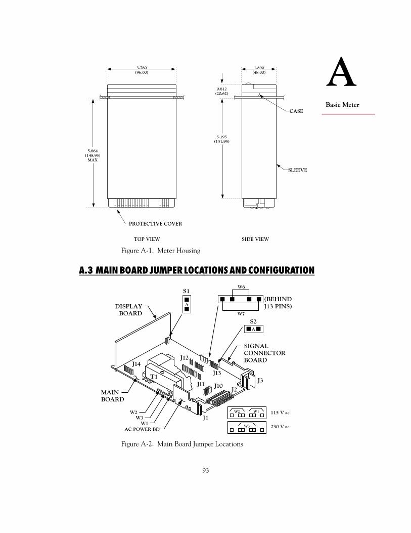
93
ABasic Meter
A.3 MAIN BOARD JUMPER LOCATIONS AND CONFIGURATION
Figure A-2. Main Board Jumper Locations
DISPLAYBOARD
SIGNAL CONNECTORBOARD
(BEHINDJ13 PINS)
MAIN BOARD
J2
J1
J3
AC POWER BDW1
W3W2
S1
A
T1
J14
A
S2
J11 J10
J13
J12
W2 W1
W3
115 V ac
230 V ac
W7
W6
SIDE VIEW
SLEEVE
CASE
3.780(96.00)
0.812(20.62)
5.195(131.95)
PROTECTIVE COVER
TOP VIEW
5.864(148.95)
MAX
1.890(48.00)
Figure A-1. Meter Housing

94
ABasic Meter
Two push-on jumpers and two wired-in jumpers on the Main Boardallow the Basic Meter to measure pulses and provide non-isolatedexcitation.
TABLE A-1. MAIN BOARD JUMPERS
LOCATION, VIEWINGTHE BOARD FROM THE
JUMPER REAR OF THE METER FUNCTION
S1-A On the right, immediately Enables push buttons tobehind the Display Board control lockout programming
S2-A First two pins of J13 on the Channels non-isolatedright side of the Main Board excitation out to P3-1;
remove if input board used
W1and W2 Left side Enables 115-V operation
W3 Left side Enables 230-V operation
W6and W7 Right side of Main Board Bypasses isolation circuitry
next to J13 used for option boards; removeif input board used
See Appendix J for factory preset settings.
For non-isolated excitation, make sure jumper S2-A is installed onthe rear two pins of J13 at the left rear of the main board.
A.4 INPUT CONNECTIONS
WARNING: Do not connect ac power to your meter until youhave completed all input and output connections. Failure to do somay result in injury! This device must only be installed electricallyby specially trained electrician with corresponding qualifications.
For the Basic Meter, input is wired to P3-2, the common ground toP3-3, and jumpers S2-A, W6 and W7 channel unregulated excita-tion to P3-1. Refer to Figure A-4.
!

95
ABasic Meter
Figure A-4. Basic Meter Wiring
A.4.1 TTL OR CMOS PULSE SOURCE
Input from the pulse source is wired to P3-2 and the commonground to P3-3. Jumpers S2-A, W6, and W7 channel unregulatedexcitation to P3-1 (14 to 20 V at 75 mA).
Figure A-5 shows the connection of a TTL or CMOS pulse sourceto the basic meter. The same wiring applies to any TTL/CMOSsource output.
Figure A-5. TTL Source to the Basic Meter
P31
2
3
TTL ORCMOS
SOURCE
N/C
SIGNAL IN
SIGNAL RETURN
The pulse source (including any wiring drop) should have a lowthreshold less than 1 V, and a high threshold greater than 3.5 Vbut not over 25 V. The meter provides a 30 kΩ pullup to its 5 Vsupply. The meter’s pullup current lifts the pulse level when thesignalling device is in the “open” state. Added external pullupcurrent can be required if you have both high pulse frequency (i.e.,higher than 5 kHz) and high capacitance (e.g., leads over 100 feetlong).
If excitation from the meter is not required, S2-A may or may notbe installed.
For pulse sources that need to be isolated from the meter’s control/output logic levels (on P2), or that need amplification, use theIsolated Pulse Input Board. See Appendix B.
P31
2
3
16-30 V UNREGULATED EXCITATION(to 75 mA)
+ TTL/CMOS INPUT PULSES
COMMON (METER SIGNAL RETURN)
SIGNAL IN
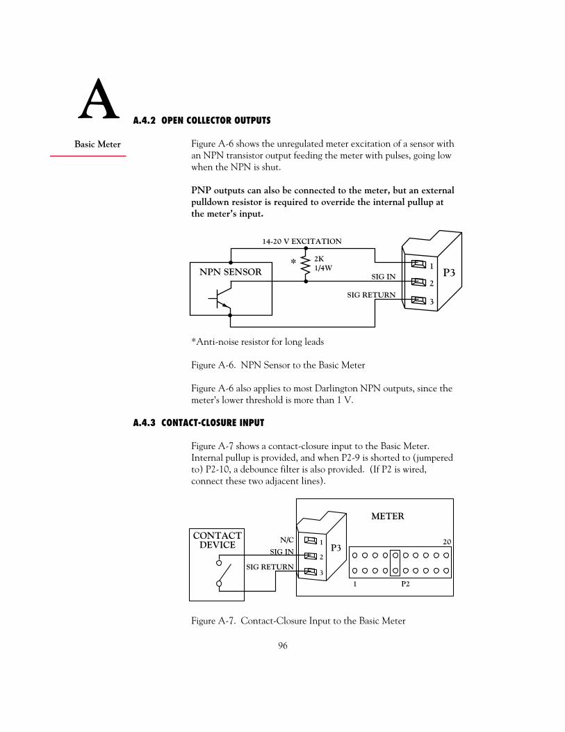
96
ABasic Meter
A.4.2 OPEN COLLECTOR OUTPUTS
Figure A-6 shows the unregulated meter excitation of a sensor withan NPN transistor output feeding the meter with pulses, going lowwhen the NPN is shut.
PNP outputs can also be connected to the meter, but an externalpulldown resistor is required to override the internal pullup atthe meter’s input.
*Anti-noise resistor for long leads
Figure A-6. NPN Sensor to the Basic Meter
Figure A-6 also applies to most Darlington NPN outputs, since themeter’s lower threshold is more than 1 V.
A.4.3 CONTACT-CLOSURE INPUT
Figure A-7 shows a contact-closure input to the Basic Meter.Internal pullup is provided, and when P2-9 is shorted to (jumperedto) P2-10, a debounce filter is also provided. (If P2 is wired,connect these two adjacent lines).
Figure A-7. Contact-Closure Input to the Basic Meter
P31
2
3
1 P2
20N/C
METER
CONTACTDEVICE
SIG IN
SIG RETURN
P31
2
3
14-20 V EXCITATION
* 2K1/4WNPN SENSOR SIG IN
SIG RETURN

BIsolatedPulse InputBoard
97
APPENDIX BISOLATED PULSE INPUT BOARD: GENERAL INFORMATION,SPECIFICATIONS, JUMPER CONFIGURATION, AND WIRING
B.1 GENERAL INFORMATION
The Pulse Input Board conditions low-amplitude pulses for bothlow-level (>20 mV rms) and high-level (up to 230 V rms) inputsignals. It provides galvanic isolation (354 V, IEC spacing),selectable hysteresis, filtering, clamping of overscale pulses, andregulated 5, 8.2 or 12.6 V excitation.
B.2 SPECIFICATIONS
SENSOR EXCITATION: 5 V @ 50mA(regulated, selectable) 8.2 V @ 50mA
12.6 V @ 70mA
CONNECTION: 2, 3-socket input plugs
INPUT SENSITIVITY LOW LEVEL: 20 mV rms HIGH LEVEL: 2 - 5 V (See Table B-2)
MAXIMUM INPUT LOW LEVEL: 60 V rms HIGH LEVEL: 230 V rms
INPUT IMPEDANCE LOW LEVEL: 100 kΩ pullup to excitation HIGH LEVEL: 150 kΩ pullup to excitation in
parallel with 90 kΩ minimum
NAMUR SENSOR 1 kΩ series resistor with 8.2 V PROVISIONS: excitation
CONTACT CLOSURE FREQUENCY RANGE: 8 ON/OFF per second

98
BIsolated
Pulse InputBoard
Figure B-1. The Isolated Pulse Input Board
Jumpers have the following functions. Factory presets are asterisked:
S1-B* Enables 12.6 V Excitation @ 70 mA (See Table B-4)S1-C Enables 5.0 V Excitation @ 50 mA (See Table B-4)S1-A Enables 8.3 V Excitation @ 50 mA (See Table B-4)None Enables 8.1 V Excitation @ 50 mA (See Table B-4)S1-D Shifts low-level thresholds positively (See Table B-3)S1-E Counts pulse on high-to-low transitionS1-F* Counts pulse on low-to-high transition
Table B-1 shows excitation voltage for different S1 positions. Thefactory preset is asterisked.
TABLE B-1. ISOLATED PULSE INPUT BOARDEXCITATION VOLTAGES
EXCITATION VOLTAGE LIMITS (V)
S1 POSITION LOWER LIMIT UPPER LIMIT
S1-B* 11.8 13.3S1-A 7.9 8.8S1-C 4.75 5.3
B.3 JUMPER LOCATIONS AND CONFIGURATION
Figure B-1 shows the Isolated Pulse Input Board jumper locations.
A DB C
S1
J9E
S1
P13
PIN 1
F
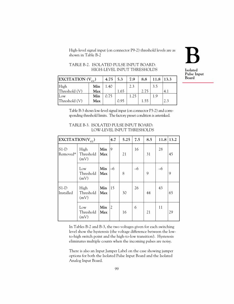
BIsolatedPulse InputBoard
99
High-level signal input (on connector P9-2) threshold levels are asshown in Table B-2
TABLE B-2. ISOLATED PULSE INPUT BOARD:HIGH-LEVEL INPUT THRESHOLDS
EXCITATION (VCC) 4.75 5.3 7.9 8.8 11.8 13.3
High Min 1.40 2.3 3.5Threshold (V) Max 1.65 2.75 4.1Low Min 0.75 1.25 1.9Threshold (V) Max 0.95 1.55 2.3
Table B-3 shows low-level signal input (on connector P3-2) and corre-sponding threshold limits. The factory preset condition is asterisked.
TABLE B-3. ISOLATED PULSE INPUT BOARD:LOW-LEVEL INPUT THRESHOLDS
EXCITATION(VCC) 4.7 5.25 7.5 8.5 11.8 13.2
S1-D High Min 9 16 28Removed* Threshold Max 21 31 45
(mV)
Low Min –6 –6 –6Threshold Max 8 9 9(mV)
S1-D High Min 15 26 43Installed Threshold Max 30 44 65
(mV)
Low Min 2 6 11Threshold Max 16 21 29(mV)
In Tables B-2 and B-3, the two voltages given for each switchinglevel show the hysteresis (the voltage difference between the low-to-high switch point and the high-to-low transition). Hysteresiseliminates multiple counts when the incoming pulses are noisy.
There is also an Input Jumper Label on the case showing jumperoptions for both the Isolated Pulse Input Board and the IsolatedAnalog Input Board.

100
BIsolated
Pulse InputBoard
B.4 HIGH-LEVEL PULSE CONDITIONING
The board’s high-level input provides a 150 k pullup to the selectedexcitation voltage (with jumpers configured as shown in Tables B-2and B-3). This input is buffered with 90 k series resistance andclamping diodes to ground and excitation so that overscale and/orbipolar pulses are readied for the 2/4 V hysteretic pulse detectionlevels (as shipped).
Tying P9-1 to ground (P3-3), provides a low-pass filter with acorner of about 8 Hz (20 ms nominal time constant) for noiserejection, suitable for relay contacts up to 8 cycles per second (withabout 50% duty cycle).
SPST (Single-Pole Single-Throw) switches can use the 1 kΩinternal resistor between the input (P9-2) and P9-3 as a pullup orpulldown, by tying P9-3 to +V or ground (P3-3), as appropriate.
B.5 LOW-LEVEL PULSE CONDITIONING
If P3-2 is used as the input instead of P9-2, very low amplitudepulses can be detected, as shown by the tables in Section B.3.Jumper S1-C is provided to optimize the detection levels forunipolar pulses: when installed, it moves the switching thresholdsup by about half of the hysteresis voltage.
The low-level input provides a 100 kΩ pullup to Excitation, 50 kΩseries resistance, and clamps to Excitation and ground. Operationover the full pulse frequency rating (20 kHz) is achieved with40mV rms, 20kHz input or 1kHz with 20 mV rms input.
B.6 EXCITATION FOR SENSORS
The tables in Section B.3 show jumper configuration producing12.6, 8.2 or 5 V of excitation to drive input devices. Like both thehigh-level and low-level inputs, this excitation is galvanicallyisolated from the rest of the meter (i.e., the control input/outputson P2).
Excitation current is limited to 50 mA. Up to 70 mA is availablewhen VCC = 12.6 is selected. However, the 12.6 V may drop to11.0 V.

BIsolatedPulse InputBoard
101
B.7 INPUT WIRING CONNECTIONS
High-level input (up to 230 V) is wired to P9-2. Low-level signals(20 mV and up) are wired to P3-2 and P3-3.
Excitation is channeled to P3-1. S1-A, S1-B or S1-C select 8.2,12.6 or 5 V excitation respectively.
Figure B-2. Isolated Pulse Input Board Wiring
B.7.1 LOW-LEVEL INPUTS
Figure B-3 shows the Pulse Input Board used to condition thebipolar output of a low-level (20 mV rms or more) magneticpickup. The regulator voltage jumper S1 should be in the S1-Cposition to lower the excitation voltage to 5 V and the thresholdbelow 20 mV.
Low-level unipolar outputs (with the same voltage swings) can bematched by using Jumper S1-D on that board, which elevates thetwo switching thresholds by approximately half of the hysteresis ofeach range.
P91
2
3
FILTER (TIE TO RETURN)
+ HIGH-LEVEL INPUT PULSES
1 K OHM PULLUP/DOWN
1
2
3
P3
ISOLATED, REGULATED VOLTAGEEXCITATION (TO 50 mA)
+ LOW-LEVEL INPUT PULSES
ISOLATED INPUT RETURN
HIGH LEVELSIGNAL
LOW LEVEL
~
~
WARNING: Do not connect ac power to your meter until youhave completed all input and output connections. Failure to do somay result in injury! This device must only be installed electricallyby specially trained electrician with corresponding qualifications.
!

102
BIsolated
Pulse InputBoard
Figure B-3. Low-level Magnetic Pickup Input to the Isolated PulseInput Board
B.7.2 NAMUR PROXIMITY SENSOR
Figure B-4 shows the use of the Pulse Input Board with a NAMURproximity sensor (less than 1 mA when ON, more than 3 mAwhen OFF). The 1 kΩ resistor is built in, and the 8.2 V excitationis obtained by removing jumpers S1-A, S1-B, S1-C, and S1-D.Installing S1-A increases the excitation by about 0.2 V.
P91
2
3
EXCITATION
SIG IN
SIG RETURN
P31
2
3
N/C
N/C
N/C
MAGNETICPICKUP
Figure B-4. NAMUR Sensor Input to the Isolated Pulse Input Board
P91
2
31K PULLDOWN
SIG
RETURN
P31
2
3
N/CNAMURSENSOR
N/COBJECTBEINGMEASURED
EXCITATION

BIsolatedPulse InputBoard
103
B.7.3 NPN TRANSISTOR OR CONTACT-CLOSURE
Figure B-5 illustrates the use of the Pulse Input Board with sensorNPN transistor or contact closure output. Contact closures benefitfrom the debounce filter connection, P9-1 to ground (P3-3).
*Use filter connection for contact closure
Figure B-5. NPN Input to the Isolated Pulse Input Board
P91
2
3
EXCITATIONIF NEEDED
SIG IN
RETURN
P31
2
3
N/C
* FILTER
OR
NPN ORCONTACT
1K PULLUP
EXCITATION
P91
2
3
EXCITATION
DARLINGTONSIGNAL IN
RETURN
P31
2
3
N/C
N/C
N/C
Darlington inputs with low-levels up to 1.9 V are accepted by thePulse Input Board. See Figure B-6.
Figure B-6. Darlington Input to the Isolated Pulse Input Board

104
BIsolated
Pulse InputBoard
B.7.4 PNP TRANSISTOR OR CONTACT-CLOSURE
Figure B-7 shows the use of the Pulse Input Board with sensor PNPtransistor or contact closure to the + excitation supply.
Figure B-7. PNP Input to the Isolated Pulse Input Board
B.7.5 LOW-LEVEL UNIPOLAR SOURCE OUTPUT
Figure B-8 shows a wiring scheme useful for low-level unipolaroutputs such as light-modulated resistances (install S1-C andS1-D).
Figure B-8. Low-Level Unipolar Input to the Isolated Pulse InputBoard
*Use filter connection for contact closure
P91
2
3
EXCITATION
SIG
RETURN
P31
2
3
N/C
* FILTER
OR
PNP ORCONTACT
1KPULLDOWN
P91
2
3
EXCITATION
SIG IN
RETURN
P31
2
3
N/C
N/C
N/CTTL LOGICW/LOW-LEVEL
UNIPOLARINPUT

BIsolatedPulse InputBoard
105
TABLE B-4. ISOLATED PULSE INPUT BOARD WIRING
JUMPERSIGNAL WIRING CONFIG- SIGNAL LEVELSOURCE CONFIGURATION URATION LOW/MIN HIGH/MAX
TTL P9-2, Signal In S1-C < 0.4 V > 2.0 VP9-3, ReturnP3-2, Leave open or tie to
high-level excitationP3-1, Excitation output;
5 V up to 50 mA
NPN P9-2, Signal In S1-B < 1.4 VOpen P3-3, To ReturnCollector, P3-2, Leave open or tie to2-or 3- high-level excitationwire P3-1, Excitation output;
12.6 V up to 70 mAP9-3, Connect to P3-1
PNP Same as NPN above, S1-B > 6 VOpen but connect P9-3 to (voltageCollector P3-3 (Return) drop on
switchmust be<6 V)
NAMUR P3-1, Excitation S1-A OFF: I ON: I2-wire P9-2, Return <1.0 mA >2.9 mA
P9-3, Connect to P3-3(Return)
Low-Level P3-2, Signal In S1-C 20 mV rms up to 1 kHzPickup P3-3, To Return 50 mV rms @ 20 kHz
P9-2, Leave open or tie tohigh-level excitation
B.7.6 WIRING TABLE
Table B-4 shows suggested wiring, jumper configuration, and signallevels for numerous Isolated Pulse Input Board signal sources.
continued next page

106
BIsolated
Pulse InputBoard
JUMPERSIGNAL WIRING CONFIG- SIGNAL LEVELSOURCE CONFIGURATION URATION LOW/MIN HIGH/MAX
Low-Level P3-2, Signal In S1-D, See SeePOT P3-3, Return S1-A for 8.2 V Table B-3 Table B-3
Excitation@ 50 mA
S1-B for 12.5 VExcitation@ 70 mA
S1-C for 5 VExcitation@ 50 mA
Contact P9-2 and P3-3, S1-B ON time OFF timeClosure Contact P9-1, > 50 ms > 75 ms
Connect to P3-3 (Return)
continued from previous page

107
CIsolatedAnalog InputBoard
APPENDIX CISOLATED ANALOG INPUT BOARD: GENERAL INFORMATION,SPECIFICATIONS, JUMPER CONFIGURATION, INPUTCONNECTIONS, AND CALIBRATION
C.1 GENERAL INFORMATION
The Isolated Analog Input Board converts voltage ranges from400 mV to 10 V and current ranges from 1 mA to 20 mA to a pulse-raterange of 0 to 10 kHz, nominal, providing 354 V of galvanic isolation (IECspacing) and excitation up to 25 mA. When the meter is equipped withthis board, it can totalize (integrate) current or voltage input and providedigital square root capability to calculate flow rate from inputs propor-tional to differential pressure.
Note that this board requires a one-time calibration. See Section C.9.
This board enables the meter to operate in the Rate Meter/Totalizer/SquareRoot Extractor Mode. This mode is shown on the display as SQ RT.
The conversion factor between input voltage or current and the output pulserate is calibrated to an exact number by using the calibration data on theback of the board and the IN.SC.OF (Input Scale and Offset) parameter.See Section C.9 for this calibration procedure.
As shipped, 4 mA produces approximately 280 Hz (or, with jumperchange, 2 kHz) and 20 mA produces approximately 8.5 kHz.
C.2 SPECIFICATIONS
CONNECTION: 3-Socket Input ConnectorSIGNAL RANGE: 0 - 5 V dc, 1 -5 V dc, 0 - 10 V dc,
0 - 1 mA dc, 4 - 20 mA dc*SENSOR EXCITATION: 24 V @ 25 mAINPUT RESISTANCE: 25 ohmsISOLATION, SIG
GND TO DIG GND: 354 VpLOW-LEVEL SHUTOFF: ProgrammableNON-LINEARITY MAX: 0.02% FSACCURACY: 0.05% FS at 25˚CTEMPCO: 50 ppm/˚C
* Calibration data are provided for 4-20 mA and 0-5 V ranges only

108
IsolatedAnalog Input
Board
C Table C-1. Isolated Analog InputBoard Range Table
RANGE USE JUMPERS
4 - 20 mA S1-B*, S1-C*, S1-E*0 - 1 mA S1-C, S1-D0 - 400 mV S1-C0 - 5 V None1 - 5 V S1-B0 - 10 V S1-A
Jumpers establish the indicated ranges with +input to P9-2 andreturn from P9-3. The factory preset condition is asterisked.
C.3 JUMPER LOCATIONS AND CONFIGURATION
J9
S1
P13S2
S2
PIN 1
AB
C
DE
A BC
There is also an Input Jumper Label on the case showing jumperoptions for both the Isolated Pulse Input Board and the IsolatedAnalog Input Board.
S2 Position Full-Scale Output Minimum Time BeforeFrequency Internal Overflow
S2-A 100 Hz +/-10% 6 MonthsS2-B* 6.4 KHz +/- 10% 60 HoursS2-C 0.77 Hz +/- 10% 50 YearsS2 Removed No output N/A
Table C-2. Isolated Analog Input Board Output Frequency Table
S2 Jumper is used to control the output frequency (internallyconnected to the main board).
When totalizing over a long period of time (more than 2 days), S2-Aor S2-C should be installed to reduce the output frequency. Therefore,the 2 billion counts internal capacity of counter is not overflowed.
Figure C-1. Isolated Analog Input Board

109
CIsolatedAnalog InputBoard
C.4 CURRENT SHUNTS
Table C-1 shows that current inputs are accommodated by placinga current shunt to ground with the meter sensitivity on the 400 mVrange. (Note: This is accomplished internally via the jumpers.)
This low current-loop voltage compliance (low voltage drop) canbe useful if the loop supply has a limited voltage range.
C.5 EXCITATION FOR SENSORS
If needed, P9-1 can supply regulated 24 V excitation up to 25 mA.
For current-loop transmitters driven by the meter’s P9-1, the returnis to P9-2, with no connection to P9-3.
For voltage-output devices or externally-powered current loops, theinput is to P9-2 and return is connected to P9-3.
C.6 NORMAL-MODE REJECTION
The Isolated Analog Input Board provides two single-pole filters intandem to provide the line-frequency rejection obtained by theselected gate time (GATE T). For the usual 0.30 s gate time, the60 Hz rejection exceeds 60 dB (e.g., a line-frequency noise of 1% offull-scale signal causes only a 10 ppm change). At 50 Hz, thisrejection drops by 3 dB, to 500:1.
C.7 RESPONSE TIME
For a step in the RATE, both RATE and TOTAL will be correct to99% after 150 ms plus one gate time of 0.10 s or longer.
C.8 INPUT CONNECTIONS
WARNING: Do not connect ac power to your meter until youhave completed all input and output connections. Failure to do somay result in injury! This device must only be installed electricallyby specially trained electrician with corresponding qualifications.
With jumpers S2-A, W6 and W7 removed, the Isolated AnalogInput Board furnishes +24 V excitation on P9-1, takes in analogvoltage/current signals on P9-2, and has the common return on P9-3. The P3 connector is not used. Refer to Figure C-2.
!

110
IsolatedAnalog Input
Board
C
Figure C-2. Isolated Analog Input Board Wiring
C.8.1 DIFFERENTIAL PRESSURE TO ANALOG INPUT BOARD
Figure C-3 illustrates a differential-pressure flow transducer drivingthe meter via a current-loop transmitter with loop power suppliedby the meter.
Figure C-3. Differential Pressure Input to the Isolated AnalogInput Board
P91
2
3
P31
2
3
N/C
N/C
N/C
METER
4-20 mA
+24-V EXCITATION
DIAPHRAMAND
POSITIONDETECTOR
CURRENT-LOOP
TRANSMITTER
FLUID FLOW
SIGNAL IN
RETURNN/C
P91
2
3
ISOLATED 24 V EXCITATION
ANALOG VOLTAGE INPUT
RETURN
SIGNAL IN
RETURN
(TEST) NC
(TEST) NC
(TEST) NC
1
2
3
P3

111
CIsolatedAnalog InputBoard
C.8.2 MULTIPHASE WATTS TRANSDUCER WITH SELF-POWERED TRANSMITTER OUTPUT
Figure C-4 shows a multiphase watts transducer with a self-poweredtransmitter output. The meter can now function as a wattmeterand a watthour meter.
Figure C-4. Multiphase Watts Transducer Connection to theIsolated Analog Input Board
C.9 ONE-TIME-ONLY INPUT CALIBRATION
Once installed, this board must be calibrated using the IN.SC.OF(Input Scale and Offset) parameter and the calibration data on theback of the board. Figure C-5 shows the back of the board and thesingle label containing the data.
P91
2
3
P31
2
3
N/C
N/C
SIG IN
RETURN
N/C
METER
4-20 mA
WATTSTRANSDUCER
ANDTRANSMITTER
(WITHINTERNAL
POWER)
N/CAC INPUTVOLTAGE
ANDCURRENT

112
IsolatedAnalog Input
Board
C 2758400
2888439
INPUT 1 @ 4 mAINPUT 2 @ 20 mAINPUT 1 @ 0 VINPUT 2 @ 5 V
Figure C-5. Back of the Isolated Analog Input Board
Reading from top to bottom, the numbers correspond to thefollowing data:
Input 1 @ 4 mA Input 2 @ 20 mA Input 1 @ 0 V Input 2 @ 5 V
The first and second numbers correspond to actual meter readingsin Hertz when the input is 4 mA and 20 mA, respectively. Theyare used as low and high data points to calibrate a board withCurrent input. The third and fourth numbers correspond to actualmeter readings in Hertz when the input is 0 V and 5 V, respec-tively. These numbers are used as low and high data points tocalibrate a board with Voltage input.
The meter takes two data points and calculates the scale (the slopeof the line defined by the two points) and the offset (the reading ifthe input signal were 0). It then automatically converts incomingsignals according to the calculated values using the followingequation:
Display reading = (Input signal + OFfset) * SCale
If you recorded the calibration data just before installing the board,they are in Section 2.3.3.2.

113
CIsolatedAnalog InputBoard
Re-write the numbers here so that they are handy when you do thecalibration:
Input 1 @ 4 mA =
Input 2 @ 20 mA =
Input 1 @ 0 V =
Input 2 @ 5 V =
The meter must be in the Rate Mode to configure IN.SC.OF.
Use Table C-3 to configure IN.SC.OF. Read from left to right,starting with the PRESS command. The first line reads, “PressMENU button repeatedly until the display shows IN.SC.OF. Youare now ready to configure IN.SC.OF.”
TABLE C-3. IN.SC.OF CONFIGURATION
THE UNTILDISPLAY THEWILL DISPLAY
PRESS: SHOW: SHOWS: COMMENTS
1 MENU IN.SC.OF You are now ready torepeatedly configure IN.SC.OF
2 /STOP INPUT 1 Enter the actual reading ofthe “low” input signal. Ifyour input is current, it willbe Input 1 @ 4 mA; if yourinput is voltage, it will beInput 1 @ 0 V:
3 /STOP 000000. Press the /DISPLAY buttonrepeatedly to set the flashingdigit; press the /STOPbutton to move to new digits
continued next page

114
IsolatedAnalog Input
Board
CTHE UNTILDISPLAY THEWILL DISPLAY
PRESS: SHOW: SHOWS: COMMENTS
4 MENU READ 1
5 /STOP 000000. Enter the value that youwould like the just-enteredINPUT 1 to show on thedisplay. This should be 0 (Hz):
Press the /DISPLAY buttonrepeatedly to set the flashingdigit; press the /STOPbutton to move to new digits
When you press the MENUbutton next, the first datapoint will be saved
6 MENU INPUT 2
7 /STOP 000000. Enter the actual reading ofthe “high” input signal. Ifyour input is current, it will beINPUT 2 @ 20 mA; if yourinput is voltage, it will beINPUT 2 @ 5 V:
Press the /DISPLAY buttonrepeatedly to set the flashingdigit; press the /STOPbutton to move to new digits
8 MENU READ 2
9 /STOP 000000. Enter the value that youwould like the just-enteredINPUT 2 to “read” on thedisplay. This should be10000 (Hz):
continued next page
continued from previous page

115
CIsolatedAnalog InputBoard
continued from previous page
THE UNTILDISPLAY THEWILL DISPLAY
PRESS: SHOW: SHOWS: COMMENTS
Press the /DISPLAY buttonrepeatedly to set the flashingdigit; press the /STOPbutton to move to new digits
When you press the MENUbutton next, the first datapoint will be saved
10 MENU OT.SC.OF You have successfullycalibrated your IsolatedAnalog Input Board, orsuccessfully calculatedIN.SC.OF
NOTE: If you receive an error message just after pressing the MENUbutton for the last time, note the message and see Appendix H.
C.10 CALIBRATING THE INPUT SIGNAL
After you calibrate the Isolated Analog Input Board, you should testthe input signal to make sure that your source is also calibrated. Ifpossible, reduce the input to 0 and note the display reading; it shouldbe 0 Hz. Then turn up the input so that it’s fully open; the displayshould read 10,000 Hz. If your readings differ significantly from these,or you see that an intermediate input level gives you the wrong meterreading, you should perform another IN.SC.OF calibration thatcalibrates both the input signal and the Isolated Analog Input Board.
There are two requirements that must be met before calibrating:
1. The scale factors of IN.SC.OF and RTE SC must be set to 1, andthe offsets of IN.SC.OF and RTE OF must be set equal to 0.
You can do this manually by accessing these parameters one by one(Section 5), or automatically by using the Automatic Scale andOffset feature. The automatic procedure is much easier.
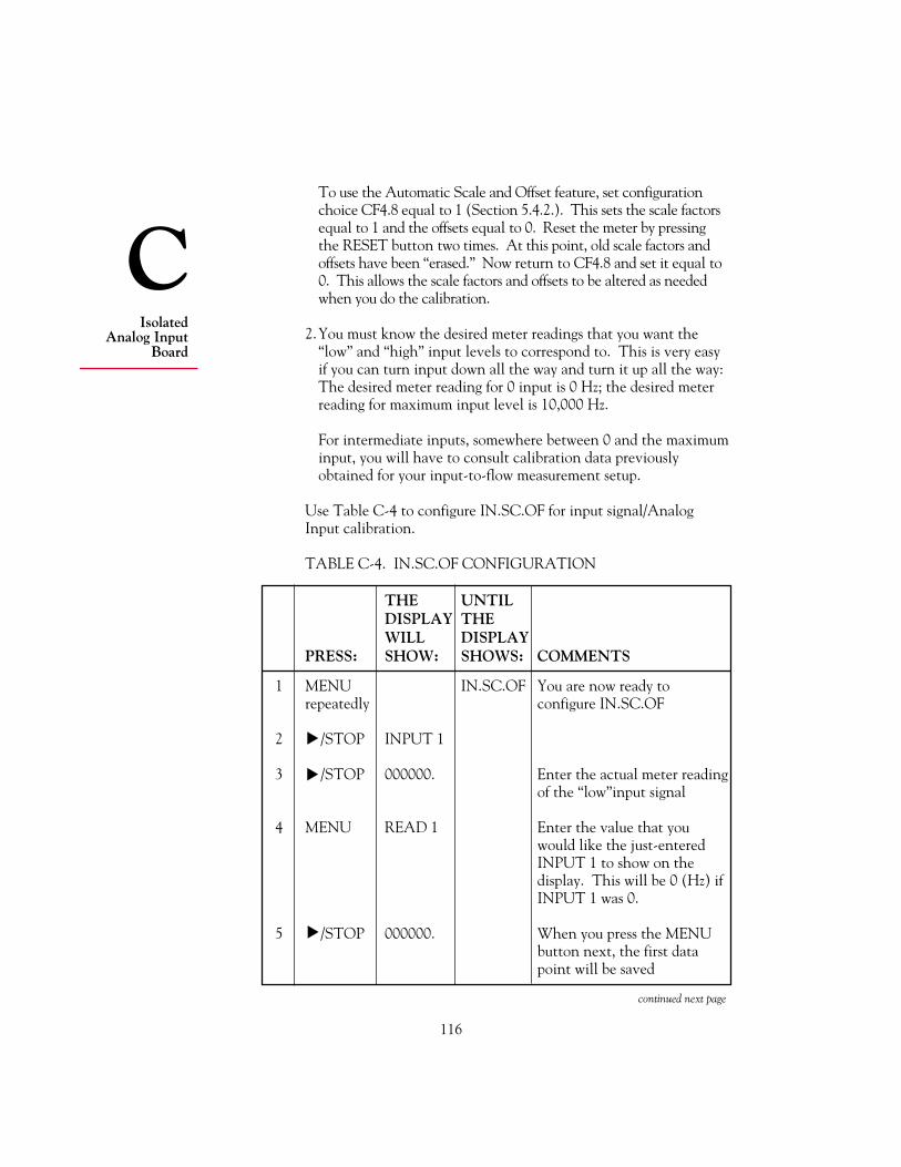
116
IsolatedAnalog Input
Board
CTo use the Automatic Scale and Offset feature, set configurationchoice CF4.8 equal to 1 (Section 5.4.2.). This sets the scale factorsequal to 1 and the offsets equal to 0. Reset the meter by pressingthe RESET button two times. At this point, old scale factors andoffsets have been “erased.” Now return to CF4.8 and set it equal to0. This allows the scale factors and offsets to be altered as neededwhen you do the calibration.
2.You must know the desired meter readings that you want the“low” and “high” input levels to correspond to. This is very easyif you can turn input down all the way and turn it up all the way:The desired meter reading for 0 input is 0 Hz; the desired meterreading for maximum input level is 10,000 Hz.
For intermediate inputs, somewhere between 0 and the maximuminput, you will have to consult calibration data previouslyobtained for your input-to-flow measurement setup.
Use Table C-4 to configure IN.SC.OF for input signal/AnalogInput calibration.
TABLE C-4. IN.SC.OF CONFIGURATION
THE UNTILDISPLAY THEWILL DISPLAY
PRESS: SHOW: SHOWS: COMMENTS
1 MENU IN.SC.OF You are now ready torepeatedly configure IN.SC.OF
2 /STOP INPUT 1
3 /STOP 000000. Enter the actual meter readingof the “low”input signal
4 MENU READ 1 Enter the value that youwould like the just-enteredINPUT 1 to show on thedisplay. This will be 0 (Hz) ifINPUT 1 was 0.
5 /STOP 000000. When you press the MENUbutton next, the first datapoint will be saved
continued next page

117
CIsolatedAnalog InputBoard
continued from previous page
THE UNTILDISPLAY THEWILL DISPLAY
PRESS: SHOW: SHOWS: COMMENTS
6 MENU INPUT 2
7 /STOP 000000. Enter the actual meter readingof the “high”input signal
8 MENU READ 2 Enter the value that youwould like the just-enteredINPUT 2 to show on thedisplay. This will be10,000 (Hz) if INPUT 2corresponded to a maximuminput level
9 /STOP 000000 When you press the MENUbutton next, the first datapoint will be saved
10 MENU OT.SC.OF You have successfullycalibrated your input signaland Isolated Analog InputBoard

118
IsolatedAnalog Output
Board
D
APPENDIX DISOLATED ANALOG OUTPUT BOARD: GENERAL INFORMATION,SPECIFICATIONS, WIRING, AND CALIBRATION
D.1 GENERAL INFORMATION
The Isolated Analog Output Board converts meter output toindependently scaled and offset unipolar voltage and/or unipolarcurrent providing 354 V of galvanic isolation (IEC spacing).When the meter is equipped with this board, it can simultaneouslytransmit voltage (to 10 V) and current (to 21 mA, and 24 mAtotal), but only one type of output is calibrated. (For preciseaccuracy on both outputs at once, the non-calibrated output mustbe calibrated for gain and offset by external means.)
Precise analog levels are generated from digital code using aproprietary ASIC chip. Load resistance for the voltage output canbe as low as 500Ω (20 mA at 10 V out) when current output is notused. Loop resistance for the current output can be as high as 600Ω(12 V compliance).
The OT.SC.OF parameter is used to convert a wide range of meterreadings to the desired current or voltage output span (see Section5.4.5).
The board can be configured to output RATE, AVG RT, andTOTAL readings in Rate and Sq Rt Modes; and BATCH count,BAT NO, and TOTAL readings in the Batch Mode. Output canalso be configured as a ramp function for slow opening and closingof electrical valves. (See Section D.5.)
D.2 SPECIFICATIONS
ACCURACY: ±0.05% of FS @ 25˚C
STEP RESPONSE: 10 to 90% full-scale 50 ms
TURNDOWN RATIO (OFFSET/SPAN): 100 with 0.01% resolution
TEMPCO: 50 ppm/˚C
LOOP RESISTANCE: up to 600Ω

119
DIsolatedAnalog OutputBoard
D.3 JUMPER LOCATIONS AND CONFIGURATION
The Isolated Analog Output Board has no jumpers. All configura-tion is done via the front panel.
D.4 WIRING/CONNECTIONS
WARNING: Do not connect ac power to your meter until youhave completed all input and output connections. Failure to do somay result in injury! This device must only be installed electricallyby specially trained electrician with corresponding qualifications.
Figure D-1. Isolated Analog Output Board Wiring Connections.
D.5 ENABLING TRANSMISSION OF ANALOG OUTPUT DATA
The output configuration of the Isolated Analog Output Board iscontrolled by setting CF3.1 (see Section 5.4.2). The settingdetermines which analog value is sent. The factory preset value isasterisked. Refer to Table D-1
TABLE D-1. ISOLATED ANALOG OUTPUT BOARD: OUTPUT CONFIGURATION AS SET BY CF3.1
RESULTING ACTIONRATE SQ RT BATCH
CHOICE SETTING MODE MODE MODE
CF3.1 0 Analog output is disabled1* RATE is sent BATCH count is sent2 AVG RT is sent BAT NO is sent3 TOTAL is sent4 Output is ramped (See Appendix K)
D.6 ONE-TIME-ONLY OUTPUT CALIBRATION
Once installed, this board must be calibrated using the four datapoints printed on the back of the board. These four points are
P51
2
3Analog Voltage0-10Vdc
Analog Current4-20mA
Analog Return
+
+
!

120
IsolatedAnalog Output
Board
D
CAL VZ (Calibrate Voltage Zero), CAL VS (Calibrate VoltageSpan), CALmAZ (Calibrate milliAmp Zero), CALmAS (CalibratemilliAmp Span). If you recorded them just before installing theboard, they are in Section 2.3.3.3.
Re-write the numbers here so that they are handy when you do thecalibration:
CAL VZ =
CAL VS =
CALmAZ =
CALmAS =
Use Table D-2 to calibrate the board. Read from left to right,starting with the PRESS command. The first line reads, “Press theMENU button repeatedly until the display shows CAL VZ. You arenow ready to calibrate the Isolated Analog Output Board.”
Table D-2. ISOLATED ANALOG OUTPUT BOARD CALIBRATION
THE UNTILDISPLAY THEWILL DISPLAY
PRESS: SHOW: SHOWS: COMMENTS
1 MENU CAL VZ You are now ready to calibraterepeatedly the Isolated Analog Output
Board
2 /STOP XXXXX The first digit will flash. Inputthe CAL VZ data point bypressing the /DISPLAYbutton to set the flashingdigit, and the /STOP buttonto move on to new digits.
When you press the MENUbutton, this value will bestored
continued next page

121
DIsolatedAnalog OutputBoard
THE UNTILDISPLAY THEWILL DISPLAY
PRESS: SHOW: SHOWS: COMMENTS
3 MENU CAL VS
4 /STOP XXXXX Input the CAL VS data point.Press the /DISPLAYbutton to set the flashingdigit, and the /STOP buttonto move on to new digits.
When you press the MENUbutton, this value will be stored
5 MENU CALmAZ
6 /STOP XXXXX Input the CALmAZ data point.Press the /DISPLAYbutton to set the flashingdigit, and the /STOP buttonto move on to new digits.
When you press the MENUbutton, this value will be stored
7 MENU CALmAS
8 /STOP XXXXX Input the CALmAS data point.Press the /DISPLAYbutton to set the flashingdigit, and the /STOP buttonto move on to new digits.
When you press the MENUbutton, this value will be stored
9 MENU The meter will immediatelyReset and revert toRun Mode
This concludes calibration.
Table D-3 (cont’d)

122
IsolatedParallel
BCD OutputBoard
E
APPENDIX EISOLATED PARALLEL BCD OUTPUT BOARD:GENERAL INFORMATION, SPECIFICATIONS, JUMPERCONFIGURATION, AND WIRING
E.1 GENERAL INFORMATION
The Isolated Parallel BCD Output Board produces binary-codeddecimal output for direct connection to a printer or to an intelli-gent device such as a PLC (Programmable Logic Controller).
E.2 SPECIFICATIONS
BCD TYPE: Isolated, stored, buffered, addressable, tri-state
DIGIT ADDRESSING: 3 or 6 digit at a time
OUTPUT LEVEL: TTL/CMOS-compatible, 10 LSTTL loads
POWER: External 5 V dc for isolated BCD; internal5 V dc for non-isolated BCD
E.3 JUMPER LOCATIONS AND CONFIGURATION
Figure E-1 shows the locations of Isolated Parallel BCD OutputBoard jumpers.
Figure E-1. Isolated Parallel BCD Output Board Jumpers
S1 S2
S4
S5
A A
A B
A
C
E
G
S3A B
S6 B
A
B
A S7
S8
A
B
J20
PIN 1
L1U1
J8

123
EIsolatedParallelBCD OutputBoard
Table E-1 shows the function of BCD board jumpers. Asteriskedjumpers are installed factory presets.
TABLE E-1. ISOLATED PARALLEL BCD OUTPUT BOARDJUMPERS
JUMPER FUNCTION
S1-A Installation brings OVERFLOW signal to P8-U18S2-A Installation enables 3-digit multiplex; removal enables
6-digit readoutS3-A Installation enables 3-digit multiplex or 1-line
board addressS3-B* Installation enables 4-line board addressS4-A Installation enables 3-digit multiplexS4-B* Installation enables 6-digit readoutS5-A P8-U20 must be low to enable board; removal enables
board when high or openS5-C P8-L20 must be low to enable board; removal enables
board when high or openS5-E P8-U19 must be low to enable board; removal enables
board when high or openS5-G P8-L19 must be low to enable board; removal enables
board when high or openS6-AS6-B Installation selects internal power; removal selectsS7-A isolated powerS7-B
S8-A Installation selects output data that is negative-trueS8-B* Installation selects output data that is positive-true
E.4 WIRINGWARNING: Do not connect ac power to your meter until youhave completed all input and output connections. Failure to do somay result in injury! This device must only be installed electricallyby specially trained electrician with corresponding qualifications.
All 6 digits of BCD are brought out to J8 (40 pins), but the upper 3digits of data can also be multiplexed onto the lower 3 digit lines sothat the data can be read 3 digits at a time if desired. J8 mates witha standard 40-pin connector, P8.
Figure E-2 shows an end-on view of P8. “U” designates the upperrow of pins; “L” designates the lower row of pins.
!

124
IsolatedParallel
BCD OutputBoard
E
U1- - - - - - - - - - - - - - - - - -U20L1 - - - - - - - - - - - - - - - - - -L20
Figure E-2. End-On View of P8
Table E-2 shows the pin assignments for P8.
TABLE E-2. P8 PIN ASSIGNMENTS
FUNCTION P8 PIN P8 PIN FUNCTION
BCD 400K L-1 U-1 BCD 800KBCD 100K L-2 U-2 BCD 200KISO GND L-3 U-3 SPAREBCD 40K L-4 U-4 BCD 80KBCD 10K L-5 U-5 BCD 20KBCD 4K L-6 U-6 BCD 8KBCD 1K L-7 U-7 BCD 2K
D.P. 2 L-8 U-8 D.P. 4BCD 400 L-9 U-9 BCD 800BCD 100 L-10 U-10 BCD 200
BCD 40 L-11 U-11 BCD 80BCD 10 L-12 U-12 BCD 20
BCD 4 L-13 U-13 BCD 8BCD 1 L-14 U-14 BCD 2
ISO GND L-15 U-15 D.P. 1DATA READY L-16 U-16 POLARITY
ISO V+ L-17 U-17 HOLDOVERFLOW L-18 U-18 OVERFLOW
ADDRESS B4 L-19 U-19 ADDRESS B8ADDRESS B1 L-20 U-20 ADDRESS B2
E.5 50-LINE CABLE COMPATIBILITY
The 40 lines of P8 are compatible with lines 9 through 48 of some50-line busses. (The left-most 8 and right-most 2 are not used bythis BCD option.)

125
EIsolatedParallelBCD OutputBoard
E.6 ENABLING TRANSMISSION OF BCD DATA
The output configuration of the Isolated Parallel BCD OutputBoard is controlled by setting CF3.2 (see Section 5.4.2). Thesetting determines which BCD value is sent.
TABLE E-3. ISOLATED PARALLEL BCD OUTPUT BOARD:OUTPUT CONFIGURATION AS SET BY CF3.2
RESULTING ACTIONRATE SQ RT BATCH
CHOICE SETTING MODE MODE MODE
CF3.2 0 BCD output is disabled1 RATE is sent BATCH count is
sent2 AVG RT is sent BAT NO is sent3 TOTAL is sent4 TIME is sent
E.7 HOLD CONTROL
P8-U17 is the HOLD line, referenced to the same ground as theBCD output (on P8-L15 and P8-L3). Pulling this line low freezesthe BCD outputs. This is useful for a slow reading device or forasymmetric cable delays.
When released, all 6 digits of the BCD data are updated together.
E.8 DATA READY TIMING PULSES
The tri-state BCD outputs are always valid to within a few nano-seconds; a single update pulse controls all digits.
To generate a timing marker, P8-L16, DATA READY, goes active lowfor approximately 200 µs at the time of each update. The polarity ofthis line is NOT CHANGED by S8, the data polarity control jumper.
E.9 BRINGING OUT THE BCD OVERFLOW LINE
P8-U18 can be used for BCD OVERFLOW by installing jumperS1-A. If this line is used for another purpose by some otherequipment on the BCD bus, remove this jumper.

126
IsolatedParallel
BCD OutputBoard
E
E.10 THREE-DIGIT-AT-A-TIME MULTIPLEX
When jumpers S2-A, S3-A, and S4-A are installed, P8-L20 andS5-C control the times when the upper 3 digits of the 6-digit BCDvalue appear on the output line (P8-U9 through P8-L14).
When jumper S5-C is installed, a LOW level on P8-L20 activatesthe upper 3 digit outputs; a high or open level disables them.
When jumper S5-C is removed, a high or open level on P8-L20enables the upper 3 digits and a low level disables them.
When the upper 3 digits are NOT enabled, the lower 3 digits canbe enabled the same way as jumper S5-A and P8-U20; they willappear on the same 12 lines.
E.11 SIX-DIGIT-AT-A-TIME BOARD ADDRESS
Jumpers S2-A and S4-A are removed for full parallel (6-digit)output.
When jumper S3-A is installed, the outputs are enabled by lineP8-L20 ALONE: A low level enables the outputs when jumperS5-C is installed, and a high or open level does the job if S5-C isremoved.
When jumper S3-A is removed, the outputs are enabled only whenthe selected 4-line address is applied to P8-U19, L19, U20, andL20. Each of these four is exclusive-ORed with its jumper, and thesubsequent four outputs are ANDed to create a 1-of-16 enablemode.
If jumper S5-A is installed, P8-U20 must be LOW to enable theboard.
If jumper S5-C is installed, P8-L20 must be LOW to enable theboard.
If jumper S5-E is installed, P8-U19 must be LOW to enable theboard.
If jumper S5-G is installed, P8-L19 must be LOW to enable theboard.

127
EIsolatedParallelBCD OutputBoard
If any of these jumpers are removed, the corresponding line must goHIGH or OPEN to assist the board enable; if all four jumpers areremoved, for example, the board outputs are enabled ONLY whenall four lines are HIGH or OPEN. A ground on any of the fourinput lines causes the outputs to go to the high impedance state.
E.12 SELECTING DATA POLARITY: JUMPER S8
Inserting the jumper in S8-B (the usual shipping position) makesthe output data (including decimal point code) positive-true.
Placing the jumper in S8-A converts the data to negative-true.
E.13 DECIMAL POINT ADDRESS CODE
P8-U15, P8-L8, and P8-U8 output a 3-digit positive-true binarycode for the location of the decimal point: 001 for the extremeright position, and 110 for the extreme left position (just to theright of the left-hand digit).
E.14 APPLYING NON-ISOLATED/ISOLATED POWER
Non-isolated power from the meter is enabled by installing jumpersS6-A, S6-B, S7-A, and S7-B. This bridges the isolation separationdistance on the board. Current drawn is less than 10 mA.
To isolate these outputs from the other meter circuits, removeS6-A, S6-B, S7-A, and S7-B, and connect an external, nominal5-V supply to P8-L17, with its ground return connected to P8-L15.
E.15 DRIVING A PRINTER
Direct connection of the 24 BCD lines and the 3 decimal pointaddress lines is all that is needed for positive-true printers thataccept a binary-coded decimal point address (which do not printthe decimal point).
If your printer has more than 6 digits, tie the unused inputs toground or V+, or leave them open (whichever produces blanks inthose locations).

128
DualRelay
OutputBoard
F
A BC
D ES1
P6
P7
3 2 13 2 1
P10
APPENDIX FDUAL RELAY AND 4 RELAY OUTPUT BOARD:GENERAL INFORMATION, SPECIFICATIONS, JUMPERCONFIGURATION, AND WIRING
F.1 GENERAL INFORMATION
The Dual Relay Output Board and 4 Relay Output Board provides twoisolated (354 V per IEC spacing, 500 test), 7-ampere Form-C electro-mechanical relays that enable setpoint-triggered switching to an externaldevice (plus two 1-ampere Form-C electro-mechanical relays for 4 RelayOption). Each relay can accommodate a single setpoint. 200 Ω, 2500pfsnubbers are provided for each normally open contact.These options may not be used with parallel BCD Board Option.
F.2 SPECIFICATIONSOUTPUT TYPE: Dual Form-C relays or 4 Form-C relaysPOWER RATING FOR RESISTIVE LOADS:
DUAL AND 4 RELAY: Two relays at P6 and P7Normally open contact, 7 amp; 30Vdc or 230VacNormally closed contact, 7 amp; 30Vdc or 230Vac
4 RELAY ONLY: Two relays at P18Normally open contact, 1 amp; 24Vdc or 30VacNormally closed contact, 1 amp; 24Vdc or 30Vac
F.3 JUMPER LOCATIONS AND CONFIGURATIONFigure F-1 shows the locations of Dual Relay Output Board jumpers, theP10 connector connecting the board to the Main Board, and the positionsof P6 and P7, the output connectors. Table F-1 shows which jumpers areassigned to each relay. Defaults are asterisked.
Figure F-1. Dual Relay Board Jumpers and Plugs
Table F-1. Dual Relay Board Jumpers
JUMPER FUNCTION
S1-A* Assigns SP 1 to Relay 1 (P6)S1-B Assigns SP 5 to Relay 2 (P7)S1-C Assigns SP 4 to Relay 2 (P7)S1-D Assigns SP 3 to Relay 1 (P6)S1-E* Assigns SP 2 to Relay 2 (P7)
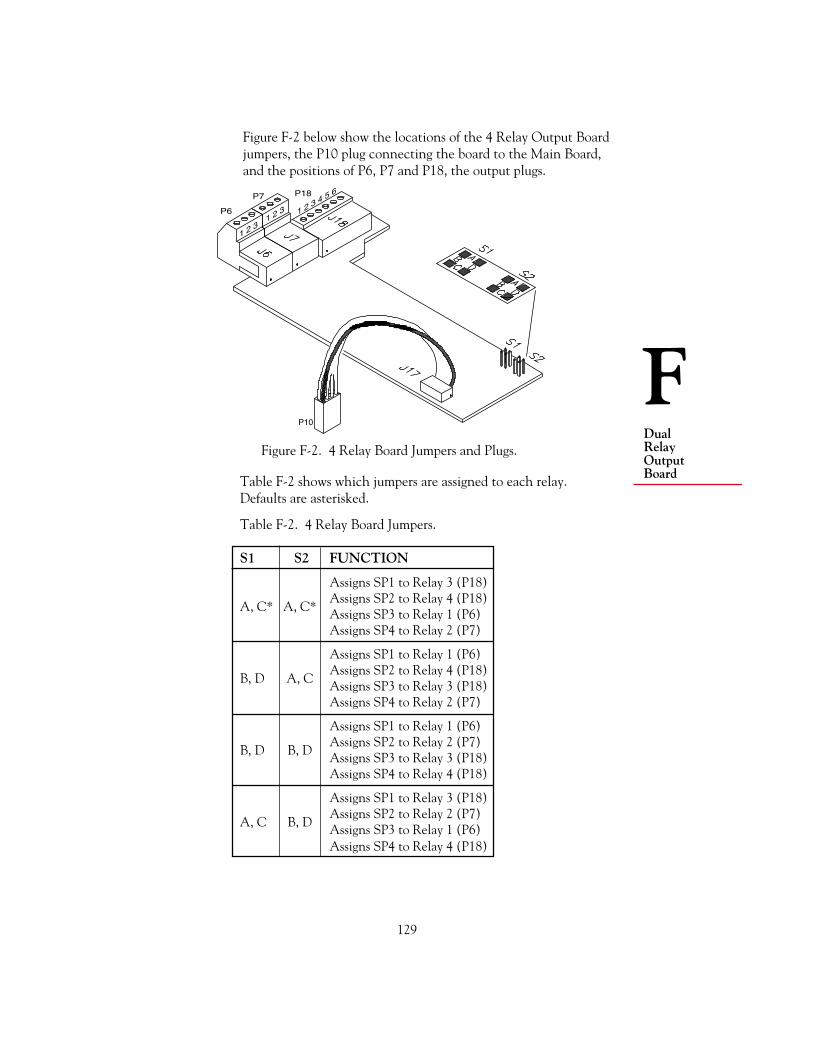
129
FDualRelayOutputBoard
Figure F-2 below show the locations of the 4 Relay Output Boardjumpers, the P10 plug connecting the board to the Main Board,and the positions of P6, P7 and P18, the output plugs.
P10
1 2 31 2 3 1 2 3 4 5 6
P6
P7 P18
Table F-2 shows which jumpers are assigned to each relay.Defaults are asterisked.
Table F-2. 4 Relay Board Jumpers.
S1 S2 FUNCTION
Assigns SP1 to Relay 3 (P18)Assigns SP2 to Relay 4 (P18)
A, C* A, C* Assigns SP3 to Relay 1 (P6)Assigns SP4 to Relay 2 (P7)
Assigns SP1 to Relay 1 (P6)Assigns SP2 to Relay 4 (P18)
B, D A, C Assigns SP3 to Relay 3 (P18)Assigns SP4 to Relay 2 (P7)
Assigns SP1 to Relay 1 (P6)Assigns SP2 to Relay 2 (P7)
B, D B, D Assigns SP3 to Relay 3 (P18)Assigns SP4 to Relay 4 (P18)
Assigns SP1 to Relay 3 (P18)Assigns SP2 to Relay 2 (P7)
A, C B, D Assigns SP3 to Relay 1 (P6)Assigns SP4 to Relay 4 (P18)
Figure F-2. 4 Relay Board Jumpers and Plugs.
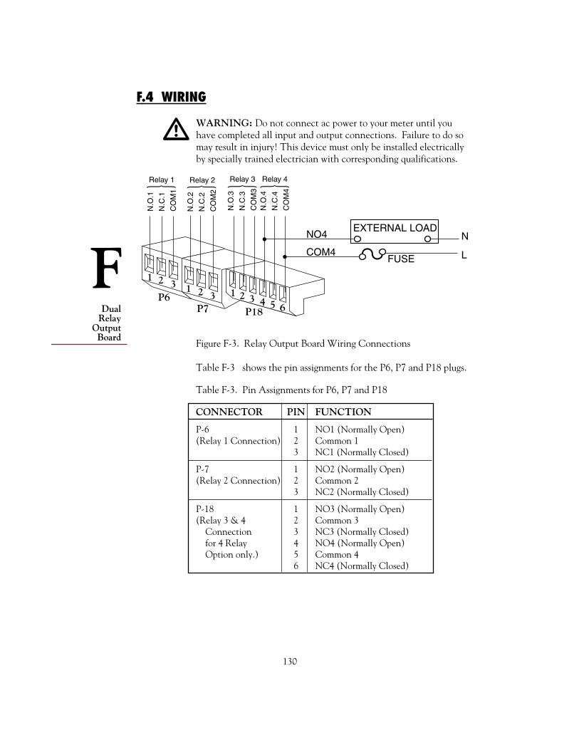
130
DualRelay
OutputBoard
F
Table F-3. Pin Assignments for P6, P7 and P18
CONNECTOR PIN FUNCTION
P-6 1 NO1 (Normally Open)(Relay 1 Connection) 2 Common 1
3 NC1 (Normally Closed)
P-7 1 NO2 (Normally Open)(Relay 2 Connection) 2 Common 2
3 NC2 (Normally Closed)
P-18 1 NO3 (Normally Open)(Relay 3 & 4 2 Common 3 Connection 3 NC3 (Normally Closed) for 4 Relay 4 NO4 (Normally Open) Option only.) 5 Common 4
6 NC4 (Normally Closed)
Table F-3 shows the pin assignments for the P6, P7 and P18 plugs.
Figure F-3. Relay Output Board Wiring Connections
1 2 3
1 2
P6P7 P18
3
Relay 3 Relay 4
N.O
.3
N.C
.3
CO
M3
N.O
.4
N.C
.4
CO
M4 Relay 1 Relay 2
N.O
.1
N.C
.1
CO
M1
N.O
.2
N.C
.2
CO
M2
EXTERNAL LOADN
LFUSE
NO4
COM4
3 4 5 621
F.4 WIRING
WARNING: Do not connect ac power to your meter until youhave completed all input and output connections. Failure to do somay result in injury! This device must only be installed electricallyby specially trained electrician with corresponding qualifications.
!
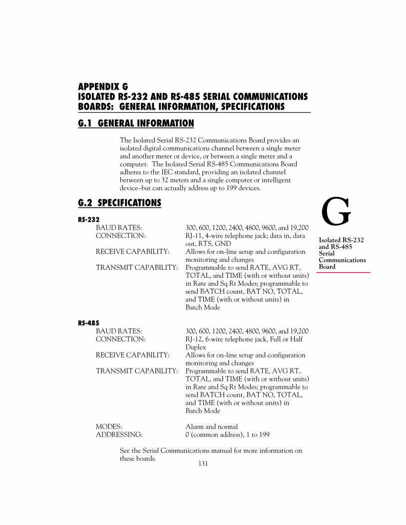
131
GIsolated RS-232and RS-485SerialCommunicationsBoard
APPENDIX GISOLATED RS-232 AND RS-485 SERIAL COMMUNICATIONSBOARDS: GENERAL INFORMATION, SPECIFICATIONS
G.1 GENERAL INFORMATION
The Isolated Serial RS-232 Communications Board provides anisolated digital communications channel between a single meterand another meter or device, or between a single meter and acomputer. The Isolated Serial RS-485 Communications Boardadheres to the IEC standard, providing an isolated channelbetween up to 32 meters and a single computer or intelligentdevice–but can actually address up to 199 devices.
G.2 SPECIFICATIONS
RS-232BAUD RATES: 300, 600, 1200, 2400, 4800, 9600, and 19,200CONNECTION: RJ-11, 4-wire telephone jack; data in, data
out, RTS, GNDRECEIVE CAPABILITY: Allows for on-line setup and configuration
monitoring and changesTRANSMIT CAPABILITY: Programmable to send RATE, AVG RT,
TOTAL, and TIME (with or without units)in Rate and Sq Rt Modes; programmable tosend BATCH count, BAT NO, TOTAL,and TIME (with or without units) inBatch Mode
RS-485BAUD RATES: 300, 600, 1200, 2400, 4800, 9600, and 19,200CONNECTION: RJ-12, 6-wire telephone jack, Full or Half
DuplexRECEIVE CAPABILITY: Allows for on-line setup and configuration
monitoring and changesTRANSMIT CAPABILITY: Programmable to send RATE, AVG RT,
TOTAL, and TIME (with or without units)in Rate and Sq Rt Modes; programmable tosend BATCH count, BAT NO, TOTAL,and TIME (with or without units) inBatch Mode
MODES: Alarm and normalADDRESSING: 0 (common address), 1 to 199
See the Serial Communications manual for more information onthese boards.

132
HError
Messages
APPENDIX HERROR MESSAGES
H.1 FLASHING ERR 01
ERR 01 indicates an OFFSET OVERFLOW. This happens whenan offset value is too large to be displayed using the correspondingdecimal point position. For example, you enter an offset value of1000, then program the decimal point 3 places to the left. Thiswould drive the resulting number, 1000.000, to seven digits,“overflowing” the 6-digit limit.
This condition must be corrected immediately because the meter isunable to continue calculations.
TO CORRECT: Press the MENU button and the meter willshow the left-most decimal point position possible for the chosenoffset. Press the MENU button again and the revised (meter-chosen) decimal point will be stored.
You can also press the RESET button. This will restore thedecimal point to the previous setting.
H.2 FLASHING ERR 02
ERR 02 indicates a SETPOINT OVERFLOW. This happens whena setpoint value is too large to be displayed using the correspondingdecimal point position. For example, you enter a setpoint value of5000, then program the decimal point 3 places to the left. Thiswould drive the resulting number, 5000.000, to seven digits,“overflowing” the 6-digit limit.
This condition is momentary; the display will flash ERR 02, self-correct by adjusting the decimal point to the far right position (notshown on the display), then return to Run Mode.
NOTE: This condition will not be shown if there is a simulta-neous Offset Overflow (ERR 01), because the display willindicate the more serious error.
TO CORRECT: When the meter flashes ERR 02, it shifts thedecimal point to accommodate the programmed setpoint value.

133
HErrorMessages
If you want to change the setpoint value as opposed to changing thedecimal position, reprogram the setpoint in the usual manner withthe SETPTS button, then adjust the decimal point accordingly.
The meter will also flash ERR 02 when the offset value forIN.SC.OF is larger than 38,000.
H.3 NOSTOR
During configuration, a NOSTOR message indicates that theattempt to store a newly set parameter or setpoint value in non-volatile memory (EEPROM) has failed. This results when theLockout Choice L3C.7 has been set equal to 1.
TO CORRECT: Set L3C.7 equal to 0. This enables nonvolatilememory storage of changed parameter values.
There are times when you may want to disable nonvolatile memorystorage (L3C.7=1) because you are changing setpoints very often(see Section 4.10.3). In this case, when you change the setpoint,the new value is written in operating memory only. The meter willdisplay the NOSTOR message–assuring you that nonvolatilememory has not been changed–but will revert to Run Mode usingthe newly configured values in operating memory. These valueswill be in effect until power is removed.
As a reminder, after changing a setpoint, make sure you store thenew value by pressing the SETPTS button. If you press the RESETbutton without first pressing the SETPTS button to store thevalue, that value is discarded and the meter continues to use the“old” value.

134
JFactory Preset
andUser Settings
APPENDIX JFACTORY PRESET CONFIGURATION SETTINGS/USERSETTINGS
This appendix shows the meter’s factory preset settings. Eachparameter contains a blank space or column entitled “User Setting”where you can enter your meter’s actual settings. This is a veryhelpful reference, especially if you have multiple meters and needto keep track of the operating parameters of each one.
The following user settings correspond to this meter:
Serial No.
Other ID
Location
Date
MAIN BOARD JUMPERS
MAINBOARD FACTORY USERJUMPERS PRESETS FUNCTION SETTING
S1-A Installed in all cases Enables Lockoutprogramming
S2-A Installed if no input board Channelsis installed non-isolated
excitation to P3-1
W1 Installed if meter Enables 115 Vand W2 is configured for 115 V Operation
operation
W3 Installed if meter Enables 230 Vis configured for 230 V operationoperation
W6 Installed if no input Bypasses isolationand W7 board is installed circuitry for
optional boards
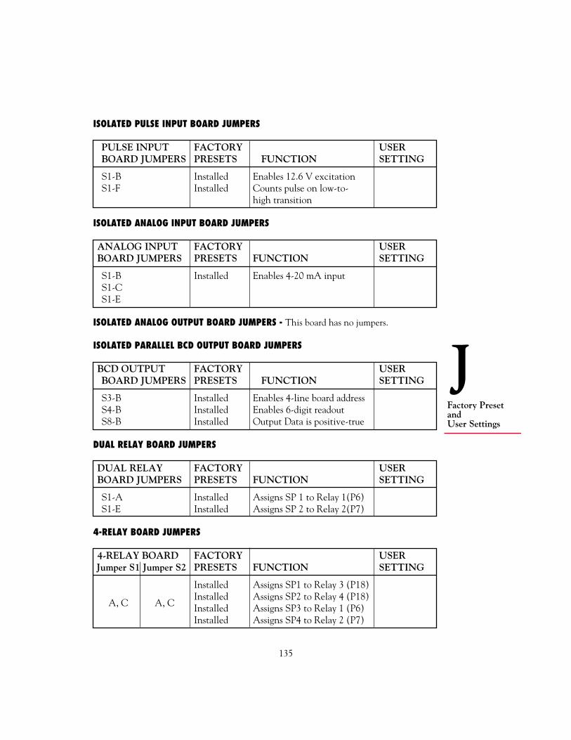
135
JFactory PresetandUser Settings
ISOLATED PULSE INPUT BOARD JUMPERS
PULSE INPUT FACTORY USERBOARD JUMPERS PRESETS FUNCTION SETTING
S1-B Installed Enables 12.6 V excitationS1-F Installed Counts pulse on low-to-
high transition
ISOLATED ANALOG INPUT BOARD JUMPERS
ANALOG INPUT FACTORY USERBOARD JUMPERS PRESETS FUNCTION SETTING
S1-B Installed Enables 4-20 mA inputS1-CS1-E
ISOLATED ANALOG OUTPUT BOARD JUMPERS - This board has no jumpers.
ISOLATED PARALLEL BCD OUTPUT BOARD JUMPERS
BCD OUTPUT FACTORY USERBOARD JUMPERS PRESETS FUNCTION SETTING
S3-B Installed Enables 4-line board addressS4-B Installed Enables 6-digit readoutS8-B Installed Output Data is positive-true
DUAL RELAY BOARD JUMPERS
DUAL RELAY FACTORY USERBOARD JUMPERS PRESETS FUNCTION SETTING
S1-A Installed Assigns SP 1 to Relay 1(P6)S1-E Installed Assigns SP 2 to Relay 2(P7)
4-RELAY BOARD JUMPERS
4-RELAY BOARD FACTORY USERJumper S1 Jumper S2 PRESETS FUNCTION SETTING
Installed Assigns SP1 to Relay 3 (P18)Installed Assigns SP2 to Relay 4 (P18)
A, C A, C Installed Assigns SP3 to Relay 1 (P6)Installed Assigns SP4 to Relay 2 (P7)

136
JFactory Preset
andUser Settings
ISOLATED RS-232 SERIAL COMMUNICATIONS BOARD JUMPERS
This board has no jumpers.
ISOLATED RS-485 SERIAL COMMUNICATIONS BOARD JUMPERS
RS-485BOARD FACTORY USERJUMPERS PRESETS FUNCTION SETTING
S1-B Installed Enables Full Duplexcommunication
SETPOINTS
SETPOINT FACTORY PRESET USER SETTING
1 100.2 200.3 300.4 400.5 12:00:00
L1 CNF, L2 CNF, L3 CNF (LOCKOUTS)
All Lockouts are set equal to 0; the corresponding meter functionsare all ENABLED.
FACTORY ENABLED USERLOCKOUT CHOICE SETTING METER FUNCTION SETTING
L1 CNF L1C.1 0 Display and setting ofSetpoints 1 and 2 throughSETPTS button
L1C.2 0 Display and setting ofSetpoints 3 and 4 throughSETPTS button
L1C.3 0 Display and setting ofSetpoint 5 throughSETPTS button
continued next page

137
JFactory PresetandUser Settings
continued from previous page
FACTORY ENABLED USERLOCKOUT CHOICE SETTING METER FUNCTION SETTING
L1C.4 0 Display and setting ofCNFG 1 parameter
L1C.5 0 Display and setting ofCNFG 2 parameter
L1C.6 0 Display and setting ofCNFG 3 parameter
L1C.7 0 Display and setting ofCNFG 4 parameter
L1C.8 0 Display and setting ofAVG.CNF parameter
L2 CNF L2C.1 0 Display and setting ofIN.SC.OF parameter
L2C.2 0 Display andsetting of OT.SC.OFparameter
L2C.3 0 Display and setting ofRTE DP, RTE OF,and RTE SC parameters
L2C.4 0 Display and setting ofTOT DP, TOT OF,and TOT SC parameters
L2C.5 0 Display andsetting of AL TIparameter
L2C.6 0 Display and setting ofBAUD, SER.CNF,DAT FT, BUS FT,ADDRES, and SER TIparameters
continued next page

138
JFactory Preset
andUser Settings
continued from previous page
FACTORY ENABLED USERLOCKOUT CHOICE SETTING METER FUNCTION SETTING
L2C.7 0 Display and setting ofSET TI parameter
L2C.8 0 Display and setting ofGATE T parameter
L3 CNF L3C.1 0 Display of RATE, SQ RT,and BATCH through the/DISPLAY button inRun Mode
L3C.2 0 Display of AVG RT, andBAT NO through the/DISPLAY button inRun Mode
L3C.3 0 Display of TOTALthrough the /DISPLAYbutton in Run Mode
L3C.4 0 Display of TIME throughthe /DISPLAY button inRun Mode
L3C.5 0 Display and setting ofMODE parameter
L3C.6 0 Display and setting ofCAL VZ, CALVS,CALmAZ, and CALmASparameters
L3C.7 0 EEPROM (non-volatile)storage of changed settings
L3C.8 0 MENU button

139
JFactory PresetandUser Settings
MODE
Factory preset MODE = Rate (Rate Meter/Totalizer Mode)
User Setting =
CNFG 1 THROUGH CNFG 4
In the following table, NC means Normally Closed.
FACTORY RESULTING ACTION USERPARAM CHOICE SETTING RATE SQ RT BATCH SETTING
CNFG 1 CF1.1 0 SP 1 NC; SP 1 SP 1 NC; SP 1assigned to assigned toTOTAL BATCH count
CF1.2 0 SP 2 NC; SP 2 SP 2 NC; SP 2assigned to assigned toTOTAL BATCH count
CF1.3 0 SP 3 NC; SP 3 SP 3 NC; SP 3assigned to assigned toRATE if BATCH countCF1.7=0; SP 3used forAVG RT ifCF1.7=1
CF1.4 0 SP 4 NC; SP 4 SP 4 NC; SP 4assigned to assigned toRATE if TOTAL ifCF1.8=0; SP 4 CF1.7=0; forused for BAT NO ifAVG RT if CF1.7=1CF1.8=1
CF1.5 0 SP 5 NC; SP 5 assigned to TIME
CF1.6 0 Meter display bright
CF1.7 0 SP 3 assigned SP 4 assignedto RATE to TOTAL
CF1.8 0 SP 4 assigned BATCHto RATE counts up
continued next page

140
JFactory Preset
andUser Settings
FACTORY RESULTING ACTION USERPARAM CHOICE SETTING RATE SQ RT BATCH SETTING
CNFG 2 CF2.1 0 SP 1 output active ABOVE SP 1value
CF2.2 0 SP 2 output active ABOVE SP 2value
CF2.3 0 SP 3 output active ABOVE SP 3value
CF2.4 0 SP 4 output active ABOVE SP 4value
CF2.5 0 SP 5 output active ABOVE SP 5value
CF2.6 0 SP 3 action RESET actionundelayed normal
CF2.7 0 SP 4 action BAT NOundelayed counts up
CF2.8 0 Meter set for 60 Hz power115 VModels
CF2.8 1 Meter set for 50 Hz power230 VModels
CNFG 3 CF3.1 1 RATE sent BATCH(Analog count sentOutput)
CF3.2 1 RATE sent BATCH(BCD count sentOutput)
CF3.3 0 SP 1 output normal (unlatched)(SP 1)
CF3.4 0 SP 2 output normal (unlatched)(SP 2)
continued from previous page
continued next page

141
JFactory PresetandUser Settings
FACTORY RESULTING ACTION USERPARAM CHOICE SETTING RATE SQ RT BATCH SETTING
CF3.5 0 SP 3 output normal (unlatched)(SP 3)
CF3.6 0 SP 4 output normal (unlatched)(SP 4)
CF3.7 0 SP 5 output normal (unlatched)(SP 5)
CF3.8 0 Cutoff disabled
CF3.9 1 Meter waits up SP 3 valueto 2 s for final converted topulse before equivalent inputcomputing pulses for fastRATE comparison
CNFG 4 CF4.1 0 External RESET A (P2-3)triggered on pulse edge
CF4.2 1 Calibrated Analog Output =Current
CF4.3 0 Display HOLD (P2-16) =disabled
CF4.4 0 Print Request (P2-16) =disabled
CF4.5 0 10-ms output Pulse output onpulse on P2-15 P2-15 low whenat end of each input rate cutRATE off, high if ratemeasurement not cut off
CF4.6 0 BCD binary address decimalpoint right justified(See Appendix E)
CF4.7 0 Front-panel RESET = enabled
CF4.8 0 Autoscof = Front-paneldisabled STOP =
disabled
continued from previous page

142
JFactory Preset
andUser Settings
AVG.CNF (Running Average Configuration)
TOTAL TOTALFACTORY PRESET VALS VALS INAVERAGE IN USER SETTING AVERAGE USER1 2 3 4 AVG 1 2 3 4 AVG
0 0 0 1 256
AVG.5 factory preset is 0 (ABC - Adaptive Bandwidth Control -Filter)
AVG.5 User Setting =
IN.SC.OF (Input Scale and Offset)
If an Isolated Analog Input Board is ordered as a part of the meterand installed at the factory, IN.SC.OF has no INPUT and READfactory presets; the board was calibrated at the factory using thecalibration data on the back of the board.
If an Isolated Analog Input Board had not been ordered, or wasordered separately using the board model number, INPUT andREAD factory preset values are a scale of 1 and an offset of 0.
User Settings: INPUT 1 =READ 1 =INPUT 2 =READ 2 =
OUT.SC.OF (Output Scale and Offset)
METER FACTORY USER USERVALUE SETTING FUNCTION SETTING FUNCTION
READ 1 0 CalibratesOUT 1 4 mA CURRENTREAD 2 10000 outputOUT 2 20 mA

143
JFactory PresetandUser Settings
RTE DP (Rate Decimal Point)
Factory setting is RRRRRR.
User Setting =
RTE OF (Rate Offset)
Factory setting is 0.
User Setting =
RTE SC (RATE Scale)
Factory setting is MULTIP; factory preset value is 000001.
User Setting =
TOT DP (TOTAL Decimal Point)
Factory setting is TTTTTT.
User Setting =
TOT OF (Total Offset)
Factory setting is 0.
User Setting =
TOT SC (Total Scale)
Factory setting is MULTIP; factory preset value is 000001.
User Setting =
AL TI (Alarm Time)
Factory setting is 0 = 00:00 (Designated setpoint is 0;alarm time is 00:00)
User Setting =

144
JFactory Preset
andUser Settings
GATE T (Gate Time)
Factory setting is 0.30 s.
User Setting =
BAUD (Data Transfer Rate)
Factory setting is 9600.
User Setting =
SER.CNF (Serial Configuration)
SER.CNF FACTORY USERCHOICE SETTING RESULTING ACTION SETTING
SER.1 1 Sets parity bit to ODDSER.2 0 Sets stop bit to oneSER.3 1 Sends long messages in
single piece
DAT FT (Data Format)
ENABLED ADDITION TO MESSAGEDAT FT FACTORY RATE SQ RT BATCH USERCHOICE SETTING MODE MODE MODE SETTING
DAT.1 1 Alarm status character
DAT.2 1 RATE value BATCHcount
DAT.3 1 AVG RT value BAT NO
DAT.4 1 TOTAL value
DAT.5 1 TIME
DAT.6 1 RATE unit of measure BATCHcountunit ofmeasure
continued next page

145
JFactory PresetandUser Settings
ENABLED ADDITION TO MESSAGEDAT FT FACTORY RATE SQ RT BATCH USERCHOICE SETTING MODE MODE MODE SETTING
DAT.7 1 AVG RT unit of measure BAT NOunit ofmeasure
DAT.8 1 TOTAL unit of measure
BUS FT (Bus Format)
RESULTING ACTIONBUS FT FACTORY RATE SQ RT BATCH USERCHOICE SETTING MODE MODE MODE SETTING
BUS.1 0 Does not add check sum to message
BUS.2 1 Adds line feed <LF> to message
BUS.3 0 Does not add command ECHO in frontof message
BUS.4 0 Sets meter to Point-to-Point Mode
BUS.5 0 Sets Point-to-Point Mode to Continuous
BUS.6 0 In Point-to-Point Mode, sets RTShandshake to Message
BUS.7 0 Sets meter for RS-232 communications
BUS.8 0 Separator for DAT FT choices 1, 2, 3,and 4 is SPACE
ADDRES (Address)
Factory setting is 001.
User Setting =
SER TI (Serial Time)
Factory setting is 1 s.
User Setting =
continued from previous page

146
JFactory Preset
andUser Settings
SET TI (Set Time)
Factory setting is 12:00:00.
User Setting =
BAT DP (Batch Decimal Point)
Factory setting is RRRRRR.
User Setting =
B LOAD (Batch Load)
Factory setting is 0.
User Setting =
BAT SC (Batch Scale)
Factory setting is MULTIP; Factory preset value is 000001.
User Setting =
CAL VZ, CAL VS, CALmAZ, CALmAS
There are no factory preset CAL VZ, CAL VS, CALmAZ, andCALmAS values: If no Isolated Analog Output Board is used, theseparameters are not used. If an Isolated Analog Output Board isordered as a part of the meter and installed at the factory, the boardhas been calibrated using exact CAL VZ, CAL VS, CALmAZ, andCALmAS values from the back of the board.
User Setting:
CAL VZ =
CAL VS =
CALmAZ =
CALmAS =

147
KRampSpecifications
APPENDIX KRAMP SPECIFICATIONS
K.1 DEFINITION
The ramping function is an output choice for the Isolated AnalogOutput Board as configured by CF3.1=4. It uses Setpoints 1 and 2to slowly open and close an electrical valve. The opening interval(the amount of time it takes to completely open the valve) isdetermined by the AL TI parameter, and the slope of the openingover time is determined by the scale of the OT.SC.OF parameter.
K.1.2 EXAMPLE
Figure K-1 shows an example of a setup where the ramp function isused. The signal source is a flow measurement from a differentialpressure flow meter that is converted to a 4-20 mA signal by theIsolated Analog Input Board. An electrical valve controls the flow toa 100,000 gallon tank. When the valve is fully open, the signal is20 mA; when the valve is fully closed, the signal is 4 mA. Figure K-2shows the graph of the valve opening and closing over time.
When the tank is ready to be filled, a RESET-A is performed. Thiscauses the electrical valve to slowly open and start filling the tank.The valve opens according to the slope of OT.SC.OF and the timespecified by AL TI, which in this case is 10 s. It remains fully opendelivering about 600 gallons per minute until Setpoint 1 is activated at
Figure K-1. A Setup Using Ramped Analog Output
VALVE4-20 mA 100,000-GALLON TANK
AL TI = 10 s STPT 1 = 99,900STPT 2 = 100,000

148
KRamp
Specifications
99,900 gallons. At this point, the filling valve starts ramping shut,using the negative slope of OT.SC.OF. It stops when it reachesapproximately 8% fullscale (about 40 gallons per minute), then closescompletely when Setpoint 2 is activated at 100,000 gallons.
Figure K-2. Opening and Closing of the Valve Over Time
K.1.3 GUIDELINES
Follow these guidelines to use the ramping function with analogoutput:
1. Assign Setpoints 1 and 2 to TOTAL (Section 4.9) and setsetpoint values as dictated by your application.
2. Set configuration choice CF3.1 to 4 (Section 5.4.2).
3. Configure OT.SC.OF (Section 5.4.5) so that the opening valveis open well before Setpoint 1.
4. Configure AL TI (Section 5.4.12) so that the Setpoint digit is 0and the corresponding time is the amount of time it takes tocompletely open the valve. This time is usually about 10 s.
SP 1 SP 2
TIME
4 mA
20 mA
RESET A

149
LSpecifications
APPENDIX LSPECIFICATIONS
L.1 BASIC METERDISPLAY
TYPE: 14-segment, red or green LEDDIGIT HEIGHT: 0.54-inch (13.7-mm)DECIMAL POINTS: Six positions, programmableLEADING ZEROS: BlankedOVERRANGE INDICATION: Displayed in exponential formatDIMMING: 100% and 50% brightness levels,
programmableDISPLAY UPDATE TIME: 0.03 to 3 seconds, programmableINDICATOR LIGHTS: 4 alarms and 3 status modes
ENVIRONMENTNORMAL OPERATING TEMP.: 0° to 50°C (32° to 122°F)DERATED OPERATING TEMP.:* 0° to 40°C (32° to 104°F)*When operating at 253V/50Hzand maximum load(4-20mA, 4 alarms on,and 75 mA excitation)STORAGE TEMP.: -40° to 85°C (-40° to 185°F)RELATIVE HUMIDITY: 90% at 40°C (non-condensing)
POWERAC VOLTAGE: 115/230Vac +/-10%CONSUMPTION: 12.5 watts, maxPOWER FAILURE: Counter values and time stored in
nonvolatile memoryAC FREQUENCY: 50/60 HzEXTERNAL FUSE PROTECTION RECOMMENDED: 115Vac IEC127-2/III, 125mA, 250V (Time-Leg)
or UL Slow-Blow, 125mA, 250V 230Vac IEC127-2/III, 63mA, 250V (Time-Leg)
or UL Slow-Blow, 63mA, 250VBATTERY BACKUP: 6-12 Vdc @ 50 mA (For internal clock only.)

150
LSpecifications
MAIN BOARDSETPOINT OUTPUT: 5 open-collector transistorsPOWER RATING: 150 mA dc @ 1 V sink, 30 V when open
GENERALTHRESHOLD: 1 V to 3.5 VPROTECTION LEVEL: 24 VFREQUENCY RANGES: 0.2 Hz to 20 kHzTRIGGER SLOPE: PositiveCONNECTION: 3-Socket Input PlugSENSOR EXCITATION: 14 to 20 V @ 25 mA non-regulatedINPUT RESISTANCE: 30 kΩ pull-up resistor to +5 VACCURACY: 0.001% of reading ±1LSD, ±trigger error
CASEMATERIAL: 94V-O UL-rated polycarbonateDIMENSIONS: (HxWxD) 1.89 x 3.78 x 5.86 in.
(48 x 96 x 149 mm)PANEL CUTOUT: 1/8 DIN (HxW) 1.772 x 3.622 in
(45 x 92 mm)
SIDE VIEW
SLEEVE
CASE
3.780(96.00)
0.812(20.62)
5.195(131.95)
PROTECTIVE COVER
TOP VIEW
5.864(148.95)
MAX
1.890(48.00)
1.772 +0.024/-.000[45.00 +0.61/-0.00]
3.622 +0.032/-.000[92.00 +0.81/-0.00]
PANEL CUTOUT
0.25 [6.4] MAX0.03 [0.8] MIN
PANEL THICKNESS
0.06[1.5]
4PLCS
R
Figure L-1. Meter Housing and Panel Cutout

151
LSpecifications
L.2 ISOLATED PULSE INPUT BOARD
SENSOR EXCITATION: 5 V @ 50 mA(regulated, selectable) 8.2 V @ 50 mA
12.6 V @ 70 mACONNECTION: 2, 3-socket input plugsINPUT SENSITIVITY LOW LEVEL: 20 mV rms HIGH LEVEL: 2 - 5 V (See Table B-2)MAXIMUM INPUT LOW LEVEL: 60 V rms HIGH LEVEL: 230 V rmsINPUT IMPEDANCE LOW LEVEL: 100 kΩ pullup to excitation HIGH LEVEL: 150 kΩ pullup to excitation inparallel with 90 kΩ minimumNAMUR SENSOR 1 kΩ series resistor with 8.2 V PROVISIONS: excitationCONTACT CLOSURE FREQUENCY RANGE: 8 ON/OFF per second
L.3 ISOLATED ANALOG INPUT BOARD
CONNECTION: 3-Socket Input ConnectorSIGNAL RANGE: 0 - 5 V dc, 1 -5 V dc, 0 - 10 V dc,
0 - 1 mA dc, 4 - 20 mA dc*SENSOR EXCITATION: 24 V @ 25 mAINPUT RESISTANCE: 25 ohmsISOLATION, SIG GND TO DIG GND: 354 VpLOW-LEVEL SHUTOFF: ProgrammableNON-LINEARITY MAX: 0.02% FSACCURACY: 0.05% FS at 25˚CTEMPCO: 50 ppm/˚C* Calibration data are provided for 4-20 mA and 0-5 V ranges only

152
LSpecifications
L.4 ISOLATED ANALOG OUTPUT BOARD
ACCURACY: ±0.05% of FS @ 25˚CSTEP RESPONSE: 10 to 90% full-scale 50 msTURNDOWN RATIO (OFFSET/SPAN): 100 with 0.01% resolutionTEMPCO: 50 ppm/˚CLOOP RESISTANCE: up to 600Ω
L.5 ISOLATED PARALLEL BCD OUTPUT BOARD
BCD TYPE: Isolated, stored, buffered, addressable, tri-stateDIGIT ADDRESSING: 3 or 6 digit at a timeOUTPUT LEVEL: TTL/CMOS-compatible, 10 LSTTL loadsPOWER: External 5 V dc for isolated BCD; internal
5 V dc for non-isolated BCD
L.6 DUAL RELAY AND 4 RELAY OUTPUT BOARD
OUTPUT TYPE: Dual Form-C relays or 4 Form-C relaysPOWER RATING FOR RESISTIVE LOADS: DUAL AND 4 RELAY: Two relays at P6 and P7
Normally open contact, 7 amp; 30Vdc or 230VacNormally closed contact, 7 amp; 30Vdc or 230Vac
4 RELAY ONLY: Two relays at P18Normally open contact, 1 amp;24Vdc or 30VacNormally closed contact, 1 amp;24Vdc or 30Vac

153
LSpecifications
L.7 ISOLATED RS-232 AND RS-485 SERIAL COMMUNICATIONS
RS-232BAUD RATES: 300, 600, 1200, 2400, 4800, 9600, and 19,200CONNECTION: RJ-11, 4-wire telephone jack; data in, data
out, RTS, GNDRECEIVE CAPABILITY: Allows for on-line setup and configuration
monitoring and changesTRANSMIT CAPABILITY: Programmable to send RATE, AVG RT,
TOTAL, and TIME (with or without units)in Rate and Sq Rt Modes; programmable tosend BATCH count, BAT NO, TOTAL,and TIME (with or without units) inBatch Mode
RS-485BAUD RATES: 300, 600, 1200, 2400, 4800, 9600, and 19,200CONNECTION: RJ-12, 6-wire telephone jack,
Full or Half DuplexRECEIVE CAPABILITY: Allows for on-line setup and configuration
monitoring and changesTRANSMIT CAPABILITY: Programmable to send RATE, AVG RT,
TOTAL, and TIME (with or without units)in Rate and Sq Rt Modes; programmable tosend BATCH count, BAT NO, TOTAL,and TIME (with or without units) inBatch Mode
MODES: Alarm and normalADDRESSING: 0 (common address), 1 to 199
See the Serial Communications manual for more information on these boards.

Warranty/DisclaimerNEWPORT Electronics, Inc. warrants this unit to be free of defects in materials and workmanship for a period ofone (1) year from the date of purchase. In addition to NEWPORT’s standard warranty period, NEWPORTElectronics will extend the warranty period for one (1) additional year if the warranty card enclosed with eachinstrument is returned to NEWPORT.
If the unit should malfunction, it must be returned to the factory for evaluation. NEWPORT’s Customer ServiceDepartment will issue an Authorized Return (AR) number immediately upon phone or written request. Uponexamination by NEWPORT, if the unit is found to be defective it will be repaired or replaced at no charge.NEWPORT’s WARRANTY does not apply to defects resulting from any action of the purchaser, including but notlimited to mishandling, improper interfacing, operation outside of design limits, improper repair, orunauthorized modification. This WARRANTY is VOID if the unit shows evidence of having been tampered with orshows evidence of being damaged as a result of excessive corrosion; or current, heat, moisture or vibration;improper specification; misapplication; misuse or other operating conditions outside of NEWPORT’s control.Components which wear are not warranted, including but not limited to contact points, fuses, and triacs.
NEWPORT is pleased to offer suggestions on the use of its various products. However, NEWPORTneither assumes responsibility for any omissions or errors nor assumes liability for any damagesthat result from the use of its products in accordance with information provided by NEWPORT,either verbal or written. NEWPORT warrants only that the parts manufactured by it will be asspecified and free of defects. NEWPORT MAKES NO OTHER WARRANTIES OR REPRESENTATIONSOF ANY KIND WHATSOEVER, EXPRESSED OR IMPLIED, EXCEPT THAT OF TITLE, AND ALL IMPLIEDWARRANTIES INCLUDING ANY WARRANTY OF MERCHANTABILITY AND FITNESS FOR APARTICULAR PURPOSE ARE HEREBY DISCLAIMED. LIMITATION OF LIABILITY: The remedies ofpurchaser set forth herein are exclusive and the total liability of NEWPORT with respect to thisorder, whether based on contract, warranty, negligence, indemnification, strict liability orotherwise, shall not exceed the purchase price of the component upon which liability is based. Inno event shall NEWPORT be liable for consequential, incidental or special damages.
CONDITIONS: Equipment sold by NEWPORT is not intended to be used, nor shall it be used: (1) as a “BasicComponent” under 10 CFR 21 (NRC), used in or with any nuclear installation or activity; or (2) in medicalapplications or used on humans. Should any Product(s) be used in or with any nuclear installation or activity,medical application, or used on humans, or misused in any way, NEWPORT assumes no responsibility as setforth in our basic WARRANTY / DISCLAIMER language, and additionally purchaser will indemnify NEWPORT andhold NEWPORT harmless from any liability or damage whatsoever arising out of the use of the Product(s) insuch a manner.
Direct all warranty and repair requests/inquiries to the NEWPORT Customer Service Department.BEFORE RETURNING ANY PRODUCT(S) TO NEWPORT, PURCHASER MUST OBTAIN ANAUTHORIZED RETURN (AR) NUMBER FROM NEWPORT’S CUSTOMER SERVICE DEPARTMENT(IN ORDER TO AVOID PROCESSING DELAYS). The assigned AR number should then be markedon the outside of the return package and on any correspondence.The purchaser is responsible for shipping charges, freight, insurance and proper packaging toprevent breakage in transit.
FOR WARRANTY RETURNS, please have thefollowing information available BEFORE contacting NEWPORT:1. P.O. number under which the product was
PURCHASED,2. Model and serial number of the product
under warranty, and3. Repair instructions and/or specific
problems relative to the product.
FOR NON-WARRANTY REPAIRS, consultNEWPORT for current repair charges. Havethe following information available BEFOREcontacting NEWPORT:1. P.O. number to cover the COST of
the repair,2. Model and serial number of product, and3. Repair instructions and/or specific
problems relative to the product.
NEWPORT’s policy is to make running changes, not model changes, whenever an improvement is possible.This affords our customers the latest in technology and engineering.NEWPORT is a registered trademark of NEWPORT Electronics, Inc.© Copyright 1999 NEWPORT Electronics, Inc. All rights reserved. This document may not be copied,photocopied, reproduced, translated, or reduced to any electronic medium or machine-readable form, inwhole or in part, without prior written consent of NEWPORT Electronics, Inc.
Return Requests/Inquiries

M1415/N/0199 11051ML-02A
For immediate technical or application assistance please call:
Newport Electronics, Inc.2229 South Yale Street • Santa Ana, CA • 92704-4426 • U.S.A.
TEL: (714) 540-4914 • FAX: (714) 546-3022Toll Free: 1-800-639-7678 • e-mail: [email protected]
Newport Technologies, Inc. 976 Bergar • Laval (Quebec) • H7L 5A1 • Canada
TEL: (514) 335-3183 • FAX: (514) 856-6886Toll Free: 1-800-639-7678 • e-mail: [email protected]
Newport Electronics, Ltd.One Omega Drive • River Bend Technology Centre
Northbank, Irlam, ManchesterM44 5EX, England
Tel: 44 (161) 777-6611 • FAX: 44 (161) 777-6622 Toll Free: 0800-488-488 • e-mail: [email protected]
Newport Electronics B.V.Postbus 8034 • 1180 LA Amstelveen • The Netherlands
TEL: (31) 20 6418405 • FAX: (31) 20 6434643Toll Free: 0800 0993344 • e-mail: [email protected]
Newport Electronics spol s.r.o.ul. Rude armady 1868 • 733 01 Karvina-Hranice • Czech Republic
TEL: 420 (69) 6311899 • FAX: 420 (69) 6311114Toll Free: 0800-1-666432 • e-mail: [email protected]
Newport Electronics GmbHDaimlerstrasse 26 • D-75392 Deckenpfronn • Germany
TEL: 49 (07056) 3017 • FAX: 49 (07056) 8540Toll Free: 0130 11 21 66 • e-mail: [email protected]
Newport Electronique S.A.R.L.9, rue Denis Papin • 78190 Trappes • FranceTEL: (33) 130-621-400 • FAX: (33) 130-699-120
Toll Free: 0800-4-63978 • e-mail: [email protected]
Mexico and Latin AmericaTEL: 95-800-639-7678 • FAX: 95-203-359-7807
En Español: (203) 359-7803 • e-mail: [email protected]
Internet [email protected]
NEWPORTnetSM On-Line Servicehttp://www.newportUS.com
® NEWPORT Electronics,Inc.
®