infinum nesting 4.0 : user manual · 7 first steps 1 first steps this manual describes how to use...
TRANSCRIPT
InfinumNesting
Align: y
Align: xIntersection
User Manual


Nesting-Handbuch
Manual version: I40U5Ge05May 2005Development: Concepts Technology Co. Ltd.Documentation:Infinum, DraftBoard and the Slogans The smart Drawing Boardund The smart Drawing program are trade marks ofConcepts Technology Co. Ltd.Other trademarks and product names are trademarks and registeredtrademarks of their respective holders.© Copyright 2005, Concepts Technology Co. Ltd. All rights reserved..
Infinum


Tabel of Contents
First Steps 7
Documentation ........................................................................... 7Registration .................................................................................. 7System Requirements ................................................................. 8Installation ................................................................................... 8Starting Infinum ......................................................................... 8
Quick Introduction 11
Nesting ....................................................................................... 11
Nesting 15
Constructing Parts and Sheets ................................................ 15Nesting Tools ............................................................................ 16Defining Parts and Material Sheets ........................................ 16Nesting Process ........................................................................ 20Nesting Analysis ....................................................................... 23


First Steps
DocumentationRegistration
System RequirementsInstallation
StartingInfinum
CHAPTER
1

7
First Steps
1
First StepsThis manual describes how to use Infinum on your computer.The Getting Started chapter briefly describes the documentation of In-finum, tells you how to install the program on your computer and useit with Microsoft Windows. It lists the type of equipment you need, tellsyou how to register your copy of Infinum and tells you how to startand end Infinum..
DocumentationThis manual describes Infinum for Windows 98/ME, Windows 2000,Windows NT4 SP5 and for Windows XP.Infinum consists of the following two parts
• Nestingand
• Constructionthat are both integrated into one program, but are described in twomanuals.The documentation of Infinum consists of the following Nestingmanual and, since the drawing tools of Infinum are identical withDraftBoard Professional, the User manual of DraftBoardProfessional .Before using this manual, you should install Infinum on yourcomputer. Installation instructions are contained in this chapter.After installation you should study the Quick Introduction chapter in theDraftBoard manual first and then continue with the chapter NestingTechniques in this Infinum manual. This will familiarize you with thetools, features and commands of Infinum and enable you to maxi-mize your productivity in the shortest amount of time.
RegistrationContrary to popular opinion, registration cards and trash aren'tsynonymous. In fact, the registration card for Infinum, convenientlylocated inside your software box, is quite valuable – to you and to us.We'd really like to encourage you to return it. Filling out theregistration card is a painless process.For such a minor investment of time, you'll become a registeredcustomer . Only by registering Infinum, are you entitled to receiveTelephone product support and Free updates
Detailed informations aboutthe user interface of yourcomputer you find in theUser Guide for MicrosoftWindows.

First Steps
8
1
System RequirementsThe system requirements for Infinum are identical with the densystem requirements for DraftBoard Expert and listed in theenclosed DraftBoard manual. In addition Infinum requires a donglefor launching the program.
InstallationInfinum comes on a CD-ROM and can be installed as a Single UserLicense for Microsoft Windows.
Single User LicenseThe Single User License will be installed as follows.
Installing a Single User License for Windows1. Start Microsoft Windows.
2. Insert the Infinum CD ROM into the CD ROM drive of yourcomputer.
3. Start the Explorer
4. In the Explorer click on the icon for your CD ROM drive.The content of the CD ROM is displayed.
5. Start the installation by double clicking the file Setup.exe.
6. Follow the directions on the screen.
7. During the installation you are asked to enter your Authori-zation Code, that you will find on the enclosed License Agreement.After the installation Infinum 4.0 is displayed in the Windows-Start menu.
8. When the installation is complete, click the OK button.The installation automatically creates the submenu Infinum 4.0in the Program menu of the Windows Start menu.This menu contains besides other entries the menu item
Infinum 4.0that will start Infinum.
You should read the Read me file first that you can open with the Readme menu item, since it contains information that was notavailable when this manual was printed.
Starting InfinumYou start and quit Infinum as follows:
1. Connect the enclosed Dongle to the parallel or USB interface ofyour computer. If you want to connect your computer to a printerusing the parallel interface, the printer cable can be connecteddirectly to the dongle.
2. Start your computer.
3. Select the menu itemInfinum 4.0
in the Infinum 4.0 submenu in the Start menu.
Terminating Infinum1. Click File in the Infinum menu bar.
The File menu is displayed.2. Select the menu item Quit in the File menu.
Important: Before you startthe installation remove anyUSB Dongle from the USBInterface. Dongles for aParallel-interface must notbe removed.

Quick Introduction
Overview of the Nesting functionality of Infinum
CHAPTER
2

11
Quick Introduction
2Quick IntroductionThis chapter gives you a short introduction into the Nesting toolsand commands of Infinum. A quick introduction into the drawingtools you find in the Quick Introduction chapter of the DraftBoard-Manual.
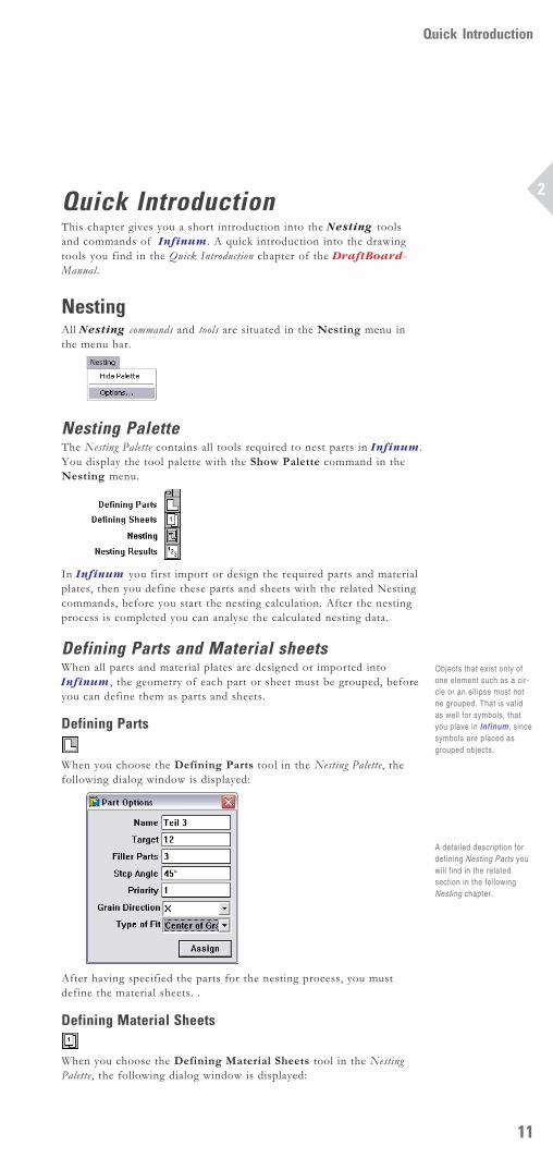
NestingAll Nesting commands and tools are situated in the Nesting menu inthe menu bar.
Nesting PaletteThe Nesting Palette contains all tools required to nest parts in Infinum.You display the tool palette with the Show Palette command in theNesting menu.
In Infinum you first import or design the required parts and materialplates, then you define these parts and sheets with the related Nestingcommands, before you start the nesting calculation. After the nestingprocess is completed you can analyse the calculated nesting data.
Defining Parts and Material sheetsWhen all parts and material plates are designed or imported intoInfinum, the geometry of each part or sheet must be grouped, beforeyou can define them as parts and sheets.
Defining Parts
When you choose the Defining Parts tool in the Nesting Palette, thefollowing dialog window is displayed:
After having specified the parts for the nesting process, you mustdefine the material sheets. .
Defining Material Sheets
When you choose the Defining Material Sheets tool in the NestingPalette, the following dialog window is displayed:
Objects that exist only ofone element such as a cir-cle or an ellipse must notne grouped. That is validas well for symbols, thatyou plave in Infinum, sincesymbols are placed asgrouped objects.
A detailed description fordefining Nesting Parts youwill find in the relatedsection in the followingNesting chapter.

Quick Introduction
12
2
Setting the Nesting optionsBefore you can start the nesting calculation, you have to specify allnesting parameters. When you select the Options command in theNesting menu the following dialog window is displayed:
After you have specified all Nesting Options you can start theNesting calculation.
Nesting Process
For the Nesting calculation you select the Nesting tool in theNesting Palette. This command nests automatically and accordingto your specifications all existing parts onto the defined materialplates.
Analysing the Nesting Data
When the nesting process is completed you can analyse the calcu-lated nesting data using the Result tool in the Nesting Palette.When you select this command the following dialog window isdisplayed:
A detailed description of all nesting tools and commands you findin the following Nesting chapter.
A detailed description fordefining Material Sheetsyou will find in the relatedsection in the followingNesting chapter.
A detailed description forspecifying the NestingOptions you will find in therelated section in the fol-lowing Nesting chapter.

Nesting
IntroductionDefining PartsDefining Plates
Nesting ProcessAnalysis
CHAPTER
3


15
Nesting
3
NestingWith Infinum you purchased a powerful Nesting program. It providesinteractive and automatic nesting of an infinite number of shaped partson any number of sheets.You can import parts or design them within Infinum. The powerfulintegrated CAD engine offers all professional tools such as for Splinesor Offset Curves for constructing parts and designing material sheets.After the definition of parts and material sheets and the specificationof all related Nesting parameters such as Collarwidth, Cutter Diameter,Clearance etc., Infinum calculates in an one step process the optimizedarrangement of the defined parts on all specified sheets.
An Analyze tool provides precise data of the optimization process. Theresults can be exported as ASCII Data.
IntroductionThe Nesting process in Infinum requires the following steps:
• Construction or Import of parts and material sheets.
• Defining parts and sheets.
• Nesting.[Calculation of the optimum arrangement of the placed parts]
• Nesting Analysis.[Evaluation of the calculated data].
Before you can nest the parts you must first design the parts or importthem into Infinum..
Constructing Parts and SheetsInfinum has an integrated CAD Engine for the construction ofnesting parts and material sheets.

Nesting
16
3
For the construction of parts and sheets you can use all in Infinumavailable geometry elements such as
• Lines• Connected Lines• Parallel Lines• Offset Curves• Arcs• Circles• Ellipses• Polygons• Spline Curves
The related tools for constructing these geometry objects you find inthe Tool palette located at the left side of the Infinum window.Instead of designing parts and sheets you can import any type ofgeometry into Infinum that was created in other CAD or Graphicprograms using the Import command in the File menu.When you have designed the parts you must group all geometryelements using the Group command in the Arrange menu. That is notrequired for elements that exist of one entity like circles, ellipses orsymbols that are already grouped when you place them into Infinum .After having designed or imported and grouped all parts, they must bedefined as parts and sheets for the nesting process..
Nesting ToolsAll commands and functions for Nesting you find in the related menusin the menu bar.All Nesting commands and tools you find in the Nesting menu in themenu bar.
When you select the Show Palette command the Nesting Palette isdisplayed.
Nesting PaletteThe Nesting palette contains all functions required for nesting inInfinum.
Show PaletteThis command displays the Nesting Palette:
For removing the Nesting Palette you select the Hide Palette commandin the Nesting menu. The Nesting Palette can be moved on the drawingarea and is handled like the DraftBoard Tool Palette. The NestingPalette contains the following functions:
All functions are described in the next sections.
Defining Parts and Material SheetsAfter you have all parts and sheets designed or imported intoInfinum, all geometry objects must be grouped, before they can bespecified as Nesting Parts or Nesting Sheets.
How to use the differenttools is decribed in theDraftBoard manual thatexplains all CAD com-mands and functions,that are integrsated intoInfinum.
A precise description ofthe Import command youfind in the DraftBoard UserManual. When you selectthe Group option whileimporting you don’t have togroup the geometry againafter having it imported.
This type of command iscalled a Toggle commandsince it toggles betweenthe two command ShowPalette and Hide Palettedepending if the NestingPalette is displayed or not.

17
Nesting
3
Objects that exist only of one entity like circles, ellipses must not begrouped. That is also valid for symbols that are already grouped whenthey are placed in Infinum.
Grouping PartsGeometry elements are grouped using the Group command in theArrange menu.
Group Ctrl+YThis command in the Arrange menu combines selected objects tofunction as a single object.
Grouping Objects1. Select the objects to be grouped..
2. Select Group from the Arrange menu.
Once you group geometry, you can’t edit the individual objectswithin the group unless you ungroup them.You can also combine groups. For hierarchical groups, Infinumungroups each group in the order in which they were combined.
Preparing Parts for the Nesting ProcessAfter having grouped all parts the must be defined for the Nestingprocess. To do so we display the Nesting Palette and select the DefiningParts tools.
Defining Parts
When you select the Defining Parts tool the Part Options dialog boxis displayed:
This dialog box allows the following settings:Name In this entry field you can name the part. The name
must be unique and may exist only once in the nestingfile.
Target This entry field requires the target number andspecifies how often you want to nest that part on alldefined material sheets.
Filler Parts In this entry field you enter the quantity of so calledFiller parts that should be nested in addition to theTarget quantity in case there remains enough roomon the sheets.In case you have defined several sheets, the parts areonly nested on sheet that contain already parts. Forplacing Filler parts you must choose the option FitFiller Parts on last Sheet in the Nesting Optionsdialog box.
Step Angle In this entry field you can specify the desired StepAngle from 0° to 360°.When calculating the arrangement of the parts on asheet, Infinum will rotate the parts around theircenter to find the optimum placement. The number ofdegrees Infinum is allowed to rotate the parts isspecified in this entry field. The smaller the specifiedstep angle the longer the calculation process will last.The default step angle is 90°.
More information aboutSymbols you find in theSymbols chapter of theDraftBoard User Manual.
A detailled description ofthe Group command youfind in the Edit Objectschapter of the Draft-Board User Manual.
Independent of the targetquantity specified, Infinumcan only nest as manyparts as there is space onthe defined sheets. Theactusal number of partsfinally nested is shown inthe Nesting Results dialogbox.

Nesting
18
3
Priority In this entry field you specify the priority a part shouldbe nested in relation to other parts. The priority isdefined in whole numbers where 1 specifies the lowestpriority.Infinum places a part with the highest prioritynumber before all other parts on the first sheet.In case parts have an identical priority, Infinumchecks the sorting parameters (Perimeter or Area)you have set in the Nesting Options dialog box.Infinum will nests than the part with the largestperimeter or area first.
Grain direction In this List Field you can choose the Grain direction(X, Y or None).If you want to nest a part independent of the Graindirection, select the option None.You can select a specific Grain direction (X or Y) only,if you have also defined a specific Grain direction forthe Material sheet.If a specific grain direction (X or Y) is defined forparts, but not for the Material Sheet (Grain direction= None), the parts will not be nested.Note: If a specific grain direction (X or Y) is defined forparts, it also must be defined for Material Sheets, Only thenthe parts will be nested.Parts with specific grain direction (X or Y) will not be nestedon sheets with none grain direction..In case parts and material sheets have specific graindirections (X or Y), Infinum will rotate all parts tomatch the grain direction of the related sheets.
Type of Fit In this list field you can select if Center of Gravity orQuicktest (Area) should be the determining parameterfor the nesting calculation.With the Quicktest (Area) option the nesting processwill be significantly faster than with the Center ofGravity option. Though the nesting calculation withthe Center of Gravity option is slower, it may lead tobetter nesting results, especially if the parts have veryirregular shapes.
If you select in the Nesting Option dialog box theFlat End method, Infinum will automatically switchto the Center of Gravity option.
Defining Parts1. Select the part you want to define.
2. Choose the Defining Part tool from the Nesting Palette.The Parts Option dialog box is displayed. The entry fields showthe parameters that were last-specified.
3. Define the part by specifying values or selecting one of theavailable options.
4. Click the Assign button.The specified parameters are assign to the part.
In the open dialog you can define additional parts. You just mustselect the next part, define the parameters and click then the Assignbutton.
Checking the assigned Parameters of Parts1. Select the Defining Part tool from the Nesting Palette.
The Parts Option dialog box is displayed. The entry fields showthe parameters that were last-specified.
2. Deselect all objects by clicking somewhere on the drawing areawith the dialog box displayed.All entry fields in the dialog box will turn blank.
3. Move the mouse over the parts without selecting them. As soonthe mouse pointer comes over a part the related part parametersare displayed in the Part options dialog window.
Setting the Nesting optionsin the section Nesting Proc-ess provides a more de-tailed description about theoptions Perimeter/Area.
19
Nesting
3
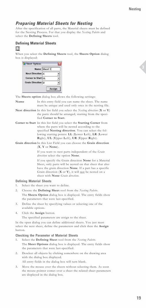
Preparing Material Sheets for NestingAfter the specification of all parts, the Material sheets must be definedfor the Nesting Process. For that you display the Nesting Palette andselect the Defining Sheets tool.
Defining Material Sheets
When you select the Defining Sheets tool, the Sheets Option dialogbox is displayed:
The Sheets option dialog box allows the following settings:Name In this entry field you can name the sheet. The name
must be unique and used only once in the nesting file.Nest direction In this list field you select the Nesting direction (X or Y)
the parts should be arranged, starting from the speci-fied Corner to Start.
Corner to Start In this list field you select the Starting Corner fromwhere the parts will be nested according to thespecified Nesting direction. You can select the fol-lowing starting points: LL (Lower Left), LR (LowerRight), UL (Upper Left), UR (Upper Right).
Grain direction In this List Field you can choose the Grain direction(X, Y or None).If you want to nest parts independent of the Graindirection select the option None.If you specify the Grain direction None for a MaterialSheet, only parts will be nested on that sheet that alsohave the grain direction None. If a part has a specificGrain direction (X or Y), it will not be nested on asheet with None Grain direction.
Defining Material Sheets1. Select the sheet you want to define.
2. Choose the Defining Sheet tool from the Nesting Palette.The Sheets Option dialog box is displayed. The entry fields showthe parameters that were last-specified.
3. Define the sheet by specifying values or selecting one of theavailable options.
4. Click the Assign button.The specified parameters are assign to the sheet.
In the open dialog you can define additional sheets. You just mustselect the next sheet, define the parameters and click then the Assignbutton.
Checking the Parameter of Material Sheets1. Select the Defining Sheet tool from the Nesting Palette.
The Sheet Options dialog box is displayed. The entry fields showthe parameters that were last-specified.
2. Deselect all objects by clicking somewhere on the drawing areawith the dialog box displayed.All entry fields in the dialog box will turn blank.
3. Move the mouse over the sheets without selecting them. As soonthe mouse pointer comes over a sheet the related sheet parametersare displayed in the dialog box.

Nesting
20
3
Nesting ProcessBefore we can calculate the arrangement of the parts on the materialsheets, we have to specify the general options for the Nesting Process.
Setting the Nesting OptionsTo set the Nesting options you must select the Options command in theNesting menu.
OptionsWhen you select this command the following dialog box is displayed:
The Nesting options dialog box allows the following settings:Flat end method When the option Flat end method option is
selected, Infinum tries to place the parts alongthe nesting direction with a minimum material waste(epitomised for minimum sheet length) and tocreate a flat end. This is done by rotating the partsin a way that the smallest side of a part shows inthe nesting direction. At the sheet end Infinumarranges the parts to create a flat end. This optionis important especially when parts are nested onendless sheets.
Height fraction In this dialog box you specify a percentage valueof the overall nesting sheet length required, whereInfinum will switch from Center of Gravity nestingto the Minimum length (flat end) method.Normally Infinum optimizes the parts accordingto their Center of Gravity, in the opposite to the Flatend method that nests parts according to their small-est extension.Since the Center of Gravity nesting requires oftenless material, you can combine both methods byspecifying a percentage value for the sheet length..Infinum then will nest parts below that valueaccording to their Center of Gravity and above thatvalue according to their minimum extension tocreate a flat end.The best results you will get with a Heightfraction between 60 % and 80 %. With 100 % In-finum would exclusively use the Center of Gravitymethod with no flat end. With 0 % Infinumwould exclusively use the Minimum Length methodwith a flat end, but the material waste could besignificantly larger than with the Center of Gravitymethod.
Fit Filler parts If that option is activated, Infinum will nest thenumber of Filler Parts specified in the Partsoptions dialog window in addition to the specifiedTarget Quantity on all sheets that contain alreadynested parts.

21
Nesting
3
On all empty sheets that were not required to nestthe specified Target Quantity no Filler parts willbe nested.If the Fit Filler parts option is not activatedInfinum will nest only the Target Quantityspecified in the Parts options dialog window.
Resolution This value specifies the Nesting Resolution. Thesmaller the resolution the more compact the partsare nested, but will require more time to calculatethe nesting.The smallest value allowed is 0,001 mm. Thelargest value must be larger than the length of thelongest sheet divided by 50 000.If the resolution is larger than this value nonesting will occur. Recommended is the defaultvalue 1.
Cutter diameter In this entry field you enter the Cutter diameterof the cutting tool you will use later to cut thenested parts.
Clearance Here you specify the Clearance between twoparts. For the absolute clearance between twoparts you must add twice the cutter diameter (foreach part).
Collar width With this value you define the minimum distanceInfinum should keep from the sheet edge.
Sort by In this list field you define according to whichparameter Infinum will place parts of equalpriority: First parts with the largest area or partswith the largest perimeter.
Color to ignore In this list field you can choose a color forgeometry objects that Infinum will ignore duringthe nesting calculation. More information aboutthis option you will find in the next section NestingCalculation.
Nesting CalculationInfinum offers the following Nesting functionality:
• True Shape Nesting
Parts with irregular shapes are nested in a way that other parts canuse the cutout of these parts.
• Multilevel Nesting
Holes and cutouts can be nested with smaller parts to achieve aminimum material waste.
• Multiple Orientation
Infinum rotates parts for an optimized arrangement by 1° steps.
• Non-rectangular Plates Support
Infinum is able to nest parts at any shape.
The Nesting calculation in Infinum is a fully automatised process,that starts as soon you select the Nesting tool in the Nesting palette.
Nesting
When you select this tool all parts will be nested fully automaticallyaccording to the specified parameters. If a nesting calculation is notpossible, an error message will be posted.
Center of Gravity NestingWith this nesting option all parts will be nested on any sheet accordingto their Center of Gravity.
Remember: The option FitFiller Parts never will starta new sheet to fill exclu-sively filler parts.
Nesting
22
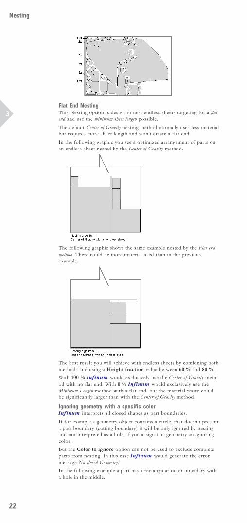
3Flat End NestingThis Nesting option is design to nest endless sheets targeting for a flatend and use the minimum sheet length possible.The default Center of Gravity nesting method normally uses less materialbut requires more sheet length and won't create a flat end.In the following graphic you see a optimized arrangement of parts onan endless sheet nested by the Center of Gravity method.
The following graphic shows the same example nested by the Flat endmethod. There could be more material used than in the previousexample.
The best result you will achieve with endless sheets by combining bothmethods and using a Height fraction value between 60 % and 80 %.With 100 % Infinum would exclusively use the Center of Gravity meth-od with no flat end. With 0 % Infinum would exclusively use theMinimum Length method with a flat end, but the material waste couldbe significantly larger than with the Center of Gravity method.
Ignoring geometry with a specific colorInfinum interprets all closed shapes as part boundaries.If for example a geometry object contains a circle, that doesn't presenta part boundary (cutting boundary) it will be only ignored by nestingand not interpreted as a hole, if you assign this geometry an ignoringcolor.But the Color to ignore option can not be used to exclude completeparts from nesting. In this case Infinum would generate the errormessage No closed Geometry!In the following example a part has a rectangular outer boundary witha hole in the middle.

23
Nesting
3
When you assign the circle an ignoring color, Infinum will handle thispart as a rectangular shaped part and will not place smaller parts withinthe hole.
Notations within and assigned to parts will be automatically identifiedand ignored while nesting.
Nesting AnalysisAfter parts have been nested the calculated data can be analyzed.
Analyzing Nesting DataThe tool for the Nesting analysis you find in the Nesting Palette.
Nesting Results
When you select this tool the following dialog window is displayed:
The Nesting Results dialog box contains the following Information:Parts/Sheets With this option NstSheets/NstParts you select
if Parts or Sheets will be displayed in the SelectionWindow.
Selection Window The Selection Window displays depending on theoption selected all parts or sheets listed in a treestructure. If you click on the + sign in front of alist item the tree is expanded displaying all objectsrelated to that item.Each tree item is followed by a number in bracketsthat indicates how often that part is nested on allsheets. If two numbers are displayed the firstnumber represents all defined parts (Target Quantity+ filler parts) and the second number shows nestedTarget quantity.
The units of all areasdisplayed correspond to theunits selected in the Unitsdialog box, that you find inthe Preferences submenuof the Layout menu. Thedefault value is mm2.

Nesting
24
3
Assumed you have selected the Sheet option andyou click on the plus sign in front of a sheet, thanall parts will be displayed that are nested on thatsheet.If you have selected the Part option all sheets willbe listed where the selected part was nested.
Result Window The Result Window lists all calculated nesting dataof a part or sheet that is selected in the SelectionWindow:
Sheet Option Sheets selected in the Selection Window:Nested PartsHere you find the number of different parts thatwere nested on that sheet.Sheet Areashows the whole area of the selected sheet.Nested Arealists the summarized area of all parts nested on theselected sheet.
Used Areashows the used area of all nested parts on thatsheet including the specified Clearances and Cutterdiameters in the Parts options dialog box.Usage (%)shows how many percent of the area of theselected sheet is used.
Parts selected in the Selection Window:Target Quantityshows the quantity specified in the Parts optionsdialog as Target Quantity for that part.Nestedshows how often this part is nested on all sheetsincluding all possible filler parts.Nested on sheet ‘Name’shows how often the selected part is nested on theselected sheet.
Part Option Part selected in the Selection WindowTarget Quantityshows the Target Quantity defined for that partin the Part Options dialog box.Nestedshows how often the selected part is nested on allsheets including any filler parts.Remaining Quantityshows how many parts of the Target Quantitywere not nested. This number does not includeany Filler Parts.Used Sheetsshows on how many sheets the selected part wasnested.
Sheets selected in the Selection WindowTarget Quantityshows the Target Quantity for that part specifiedin the Part Options dialog box.Nestedlists how often the related part is nested on theselected sheet including any possible Filler Parts.Nested on sheet ‘Name’shows how often the selected part is nested on theselected sheet.
View When you select this option the View window isdisplayed showing the selected part or sheet.

25
Nesting
3
Export When you click this button the Save as dialogwindow is displayed, where you can specify a namefor the data you want to export. As soon as youclick the Save button all Nesting Results are savedas ASCII File.
Show When you click this button the selected part orsheet is selected on the drawing area and displayedat full screen size.
