influence gn etic field mar'm:' uperalloy y · influence_gn etic field _...
TRANSCRIPT

_rt on:
iNFLUENCE_GN ETIC FIELD
_ MAR'M:' UPERALLOY
Y
- Depa_ment . ........................ ,race & En.gineering_ -i:-...............°-_:_d_University of Alabama at Birmingham
- __- BirmJngB_-_--, Alabama 35294
_ , DJanne Schmidt: _ Materialsand Processes Laboratory-N_ASA'/Geoig_:_'°__iiSpace _Flight Center
MarShall Space Flight Center, Alabama 35812
, 1-36461George C. spa-ce Flight Center
Marshall Space Flight Center, Alabama 35812
1991
https://ntrs.nasa.gov/search.jsp?R=19910013103 2018-06-23T11:19:39+00:00Z

Final Technical Report on:
= =b INFLUENCE OF A MAGNETIC FIELD
DURING DIRECTIONAL SOLIDIFICATION
OF MAR-M 246 + Hf SUPERALLOY
---H_=
ami
m
R
Submitted by
J. Barry AndrewsDepartment of Materials Science & Engineering
University of Alabama at BirminghamBirmingham, Alabama 35294
and
Wendy Alter, Dianne SchmidtMaterials and Processes Laboratory
NASA/George C. Marshall Space Flight CenterMarshall Space Flight Center, Alabama 35812
for
NASA Contract NAS8-36461George C. Marshall Space Flight Center
Marshall Space Flight Center, Alabama 35812
January, 1991

TABLE OF CONTENTS
- i
m
w
ABSTRACT .......................... i
INTRODUCTION ........................ 1
MICROSTRUCTURE - PROPERTY RELATIONSHIPS IN SUPERALLOYS .... 3
SOLIDIFICATION UNDER A MAGNETIC FIELD ........ 5
The Influence of a Magnetic Field on Solute Banding . . . 7
The Influence of a Magnetic Field on Segregation . . . 8The Influence of a Magnetic Field on Microstructure . . 9
OBJECTIVE OF THE CURRENT INVESTIGATION ........... 11
RESEARCH APPROACH .......... 13
The Usefulness of Shape'Factor Measurements ...... 15
EXPERIMENTALPROCED E..._ ............... 17Directional Solidification ............... 17
Analysis ........................ 22
RESULTS AND DISCUSSIONS ................... 23
Stereological Measurement .......... - - - . 25
Carbide Volume Fraction ...... ..--. [.. 25Volume Fraction of the Interdendritlc E t ciu e t c . . 27
Secondary Dendrite Arm Spacing .......... 29
Primary Dendrite Arm Spacing ........... 30
Chemical Analysis .....- - - 31Solidification Under'Cyclic Field Conditions . . . 36
CONCLUSIONS .......................... 45
ACKNOWLEDGEMENTS ...................... 48
REFERENCES ......................... 49
APPENDIX - MICROPROBE ANALYSIS AREAS ............ 51

ABSTRACT
An area that has been almost totally overlooked in the optimization
of properties in directionally-solidified superailoys is the
control of microstructural features through the application of a
magnetic field during solidification. This project was designed
to investigate the influence of a magnetic field on the
microstructural features of a nickel-base superalloy. _ Studies were
carried out on the dendritic MAR-M 246+Hf alloy, which was
solidified under both a 5K gauss magnetic field and under no-
applied-field conditions. The possible influences of the magnetic
field on the solidification process were observed by studying
variations in microstructural features including volume fraction,
surface area, number and shape of the carbide particles.
Stereological factors analyzed also included primary and secondary
dendrite arm spacing and the volume fraction of the interdendritic
eutectic constituent. Microprobe analysis was carried out to
determine the chemistry of the carbides, dendrites and
interdendritic constituent and how it varied between field and no-/
field solidified samples. Experiments involving periodic
application and removal of the magnetic field were also performed
in order to permit a comparison with structural variations observed
in a MAR-M 246+Hf alloy solidified during KC-135 high-g, low-g
maneuvers.

m
= :
INTRODUCTION
One of the major goals in the area of solidification research
today is the control of microstructural features in order to
produce components that exhibit outstanding properties. Proper
control is of particular importance in the production of
sophisticated superalloy parts by directional solidification
processes. However, control of microstructures to date has been
primarily limited to modification of alloy composition and to
variations in thermal gradients and solidification rates during
solidification. A recent investigation has shown that directional
solidification under low gravity conditions can lead to changes in
the dendrite arm spacing, the volume fraction of carbides formed,
and the amount of interdendritic segregation in superalloys. It
is likely that solidification under other conditions that reduce
fluid flow in advance of the solid-liquid interface can alter
microstructures as well. One possibility of inhibiting this fluid
flow is through solidification under a magnetic field.
A major limitation in obtaining desirable microstructures in
superalloys is the difficulty in controlling the solidification
process in such a way that several microstructural features can be
optimized. It is well known that the degree of segregation, the
dendrite arm spacing, the amount of interdendritic phase, and the
carbide volume fraction, distribution and morphology all influence
the mechanical properties of advanced Ni-based superalloys 2. The
benefits that can be gained through control of microstructural

r
w
r
w
w
k_
L
E_
L
w
u
features, particularly carbide volume fraction, shape and
distribution, is expected to be significant. However, control of
all of these features during solidification is not currently
feasible.
One serious hinderance to understanding microstructural
evolution during directional solidification has been the inability
to impede gravitational and non-gravitational driven flows. 3
Studies performed as early as 1966 indicated that fluid flow could
essentially be stopped by solidification under a magnetic field. 4
Performance of solidification experiments under the influence of
a magnetic field can dampen both gravitational and non-
gravitational driven flows. It is hoped that the increased level
of understanding of the solidification process obtained from these
experiments may eventually lead to the ability to produce
microstructures of desired morphologies.
The purpose of this research program was to investigate the
influence of a magnetic field on the microstructural features
obtained during directional solidification of the dendritic
superalloy, MAR-M 246+Hf. Testing was carried out using both
steady magnetic field and alternating field conditions.
w
w2

w
I
II
I
I
w
MICROSTRUCTURE-PROPERTY RELATIONSHIPS IN SUPERALLOYS
It is well known that variations in the thermal gradients and
solidification rates during directional solidificatlon can lead to
changes in the mlcrostructural features of the alloy solldified. 5
These microstructural changes can have a significant influence on
the properties of the alloy. In superalloys, the principal
microstructural variables include:
1. the carbide amount and morphology
2. the amount of the interdendritic constituent
3. the primary and secondary dendrite spacing.
Microstructural control is achieved through composition
selection or modification as well as through the control of
processing variables.
The influence of some microstructural features on alloy
properties has not been rigorously determined. One area in which
this is the case is the influence of carbide morphology and
distribution on the properties of certain nickel-base superalloys. 2
This includes the MAR-M 246+Hf alloy currently in use in the Space
Shuttle Main Engine (SSME) turbopumps. Either script or blocky
carbide morphologies can be obtained in this alloy. Surprisingly,
there is no clear cut answer as to which form is preferable in
particular applications.
In general, the advanced nickel-base superalloys, such as the
MAR-M 246+Hf, contain substantial levels of aluminum and titanium
which strengthen the austenitic matrix through precipitation of
3

E
W
w
-- k_W
a_w
L_
w
w
\
Ni3(AI,Ti), an ordered, FCC compound referred to as "gamma prime"
(7'). 6 The carbides MC, M23C6, and M6C provide llmited matrix
strengthening through dispersion hardening. However, their
dominate role is stabilization of grain boundaries against
excessive shear. 2
Carbides can exert a profound influence on properties by their
precipitation on grain boundaries. 2 The distribution of carbides
in cast superalloys can be marginally modified by heat treatment.
However, true solutionizing, in which all minor constituents are
dissolved, is not considered feasible in most nickel-base
superalloys since the MC carbides usually will not totally dissolve
without incipient melting of the alloy.
Matrix and grain boundary carbides can have a negative
influence on alloy mechanical properties. 2 Oxidized carbides or
precracked carbides from machining or thermal stresses can initiate
fatigue cracks. Both carbide size and shape is important. Reduced
carbide volume fractions and sizes result in a reduction of
precracked carbides. In addition, it is generally assumed that
carbides of a script morphology are more likely to lead to fatigue
crack formation than blocky carbides. However, testing of this
latter assumption is difficult because it is almost impossible to
obtain samples in which the only microstructural variation is
carbide morphology. A variation in solidification rate can lead
to changes in carbide morphology under some circumstances, for
example, from a blocky to a script type structure. However,
variations in dendrite arm spacing and other mlcrostructural
4

w
r_
m
_--2
features usually occur at the same time, making determination of
the influence of carbide morphology alone difficult.
Directional solidification under low-gravlty conditions has
been shown to influence microstrucural features considerably. ! It
is expected that solidification under a magnetic field will
severely restrict the movement of fluid in advance of the
solidification front and result in a significant microstructurai
change as well. Through proper control of the solidification
process and magnetic field, it may be possible to produce alloys
with controlled microstructural features.
SOLIDIFICATION UNDER A MAGNETIC FIELD
L_
The influence of a magnetic field on the solidification
process has been studied for well over two decades. From the
earliest studies 4 it has been apparent that the major influence of
a magnetic field during solidification is one of restricting fluid
movement. Thermal convection in electrically conducting fluids is
inhibited by the application of a magnetic field, since motion of
the conducting fluid across magnetic field lines is subject to
inductive drag. 4 The primary effect is one of apparent increased
liquid metal viscosity in the presence of the field. This is a
useful concept for analyzing some of the more straight forward
circumstances encountered. Unfortunately, the solidification
process, particularly when convection due to both thermal and
compositional gradients is involved, is complex problem. 7 In
5

m
L
w
. =
addition, a magnetic field may influence the solidification process
in other ways than Just restricting fluid flow.
While increased apparent viscosity is an easily grasped
concept, it does not completely describe the actual influence of
a magnetic field. For example, early theoretical investigations
treating the influence of a magnetic field on thermal convection
in a conducting fluid indicated that field orientation relative to
the gravitational vector should be of importance. 8'9 It has been
suggested that the magnetic field should be oriented parallel to
the gravitational vector if convection is to be most effectively
suppressed.
There is no question that magnetic fields can have a
considerable influence on the solidification process. The few
studies that have been carried out have shown this.
reported changes resulting from the presence of
been somewhat inconsistent.
modification is expected,
parameters have been reported.
Although some
no quantitative
It is essential that an indepth
However, the
the field have
microstructural
microstructural
study be carried out to determine the influence of a magnetic field
on the microstructures developed. For superalloys, although many
of the microstructures obtained are complex, quantitative
microscopy methods exist for characterizing most of the
microstructural parameters of importance. The following sections
cover the findings that have been reported to date concerning the
influence of a magnetic field on the solidification process. The
literature search revealed no studies involving superalloy systems.

The Influence of a Magnetic Field on Solute Banding
= =
W
E_IQw
W
w
-w-
w
Directional solldification of alloys, particularly when
horlzontal growth directions are utilized, often leads to solute
banding. Most of the early studies involving solidification in the
presence of a magnetic field were concerned with the elimination
of this solute banding in horizontally solidified samples. I°'II The
banding, which resulted from turbulent convection currents, was
found to be effectively eliminated with the application of a
vertically oriented magnetic field. Later studies which
investigated the magnetic flux densities required to suppress
convection in molten tin, indicated that for a horizontal
temperature gradient of 10°C/cm, a flux density of approximately
500 Gauss was sufficient to prevent turbulent convection. 4
However, laminar convection was found to continue until flux
densities approaching 2000 Gauss were applied. It was also noted
that the horizontal temperature gradient in advance of the
solidification front was substantially increased in the presence
of the magnetic field; presumably because of a significant
reduction in the convective mode of heat transfer.
In 1980, Coriell, et al. carried out a study concerned
primarily with modeling convective and interfacial instability
criteria during directional solidification. It was indicated in
this analysis that a vertical magnetic field would increase the
critical concentration required for convective instabilities. For
the system analyzed (Pb-Sn), a field of i0,000 Gauss was needed to

F---
cause an order of magnitude change in the critical concentration.
While high field strengths may be necessary, this work did indicate
that a magnetic field could actually prevent the onset of
convection.
W
L
E
w
The Influence of a Magnetic Field on Segregation
Several studies have indicated that solidification under a
magnetic field will alter the solute distribution in a sample. For
example, in 1966, Utech et al. 12 found that a vertical magnetic
field of 3500 G applied to a tin - i% bismuth sample directionally
solidified in an open horizontal boat resulted in a more uniform
composition profile. Work performed by Sanghamitra and Wilcox 13 in
1978 studied vertical directional solidification of an InSb -GaSb
alloy with and without a horizontal magnetic field. In this work,
segregation was not influenced by the presence of the magnetic
field for slow growth rates and high thermal gradients. However,
the composition of samples solidified at higher rates was
influenced by the field. Since a greater effect was noted at the
high growth rates, the authors concluded that the magnetic field
was effective in reducing buoyancy driven natural convection, but
did not eliminate it.
It would appear that if the primary influence of a magnetic
field was to limit convection, solidification under a magnetic
field would prevent disruption of the solute boundary layer and
mixing in the liquid.This should result in a more uniform

w
longitudinal compositional profile during planar growth front
conditions.
Lm
C
n
u
Ine
m
The Influence of a Magnetic Field on Microstructure
One shortcoming of the solidification process is the inability
to independently control several of the more significant
microstructural features of an alloy. This is particularly true
in the more complex, multicomponent alloys such as superalloys.
While many of these features are obviously interrelated, there
are many that can theoretically be independently varied. This is
particularly true in the more complex, multicomponent alloys such
as superalloys. Proper control of the carbide and dendritic
structures in some superalloys could have a significant influence
on their properties.The application of a magnetic field gives a
means of microstructural control that may make optimization of
these microstructures possible.
The influence of magnetic fields on the microstructures
obtained during directional solidification has been a topic of
considerable interest for some time. One of the first
investigations to address microstructural variations in metal
systems due to the presence of a magnetic field was carried out in
1969 by Sahm. 14 The gold-cobalt eutectic system studied was
somewhat specialized in that the Curie Temperature of the cobalt
phase was higher than the eutectic temperature. During vertical
directional solidification of eutectic and off-eutectic alloys, a
9

L _
-- r
h
m
magnetic field applied parallel to the growth direction was found
to coarsen the Co-phase in the fibrous composite structure. In
addition, for hypereutectic alloys, an orienting effect on the
primary Co-dendrites was noted due to the field. A more detailed
report at a later date 15 indicated that the shape and size of the
eutectic fibers was modified by the field as well. This was though
to be due to a field induced enhancement of the local temperature
gradient.
On the other hand, not all studies have reported significant
effects due to solidification in a magnetic field. Work reported
by Verhoeven and Pearson in 197318 stated that eutectic Sn-Cd and
Sn-Pb alloys solidified vertically were not influenced by a
transverse magnetic field. No effect was found on the spacing or
orientation of the lamellar structure. They concluded that
lamellar spacing could not be controlled by a magnetic field. It
should be pointed out that directional solidification of an a11oy
of eutectic composition would not have resulted in the formation
of a solute boundary layer. It is this boundary layer which is
usually influenced by convection and would have the highest
possibility of being altered by the presence of a magnetic field.
As a result, Verhoven and Pearsons Is findings are not all that
surprising.
A more recent study carried out by Aoki et al. 17 involved
vertical directional solidification of a hypoeutectic AI-Si alloy
in a vertical magnetic field. It was found that application of the
field resulted in a drastic change in the number of dendrites
10

D
present; going from many to a single large dendrite when the
magnetic field was applied. Removal of the field resulted in the
opposite effect. Unfortunately, in the sample processed, removal
of the field also coincided with impingement of the single dendrite
on the crucible wall. Aoki et al. 17 concluded that the influence
of the field was to suppress dendrite formation. However, their
results could be interpreted to indicate coarsening in the presence
of a field as well; a finding that would be in agreement with that
of Sahm 14 in 1969.
This summarizes most of the studies carried out to date
concerning microstructural modification caused by the presence of
a magnetic field during solidification. The reported findings show
different influences of magnetic fields on microstructures among
the alloy systems investigated. In some cases major changes
resulted. However, no changes were found in other cases.
Unfortunately, there is currently no fundamental explanation of
these interesting observations and much obviously remains to be
learned concerning the modification of microstructures through the
use of magnetic fields.
OBJECTIVE OF THE CURRENT INVESTIGATION
In this study, a currently utilized superalloy, MAR-M 246+Hf,
was solidified under both no magnetic field and magnetic field
conditions in order to determine the influence of the field on
microstructural features. The magnetic field applied during
11

W
wm_
solidification was expected to have a considerable influence on
the microstructures obtained. Field orientation may have an effect
as well. A horizontal field orientation was utilized in this
investigation due to experimental restrictions. However,
experiments should eventually be carried out using a field
direction parallel to the gravitational vector.
These experiments quantitatively compare the microstructural
features of MAR-M 246+Hf, directionally solidified with and without
the influence of a magnetic field. This is a significant departure
from the majority of prior solidification studies. The benefits
of taking a quantitative approach will be a detailed description
of the way in which microstructural features are varied through
manipulation of the solidification process by the use of magnetic
fields.
12

r
w
w
w
w
m
RESEARCH APPROACH
A MAR-M 246+Hf, nickel base superalloy was utilized in this
investigation. This alloy was selected because of the vast
experience of NASA personnel working with the alloy and due to the
possibility of comparing the field solidification experiments with
low-g, high-g solidification experiments performed during parabolic
maneuvers in NASA's KC-135 zero-g aircraft.
A detailed investigation of microstructural features was
carried out under a) no field conditions, b) under steady field
conditions, and c) under cyclic field conditions. A vertical
solidification direction was used to facilitate processing and
permit a comparison of results with those obtained through
solidification during alternating gravity level conditions. A
horizontal magnetic field orientation was utilized.
It is common in investigations of this nature to alter
conditions during the solidification experiment by varying some
pertinent external parameter. This permits a determination of the
influence of the variable through comparison of different regions
on the same sample. For example, in the current project this could
be done in order to determine the influence of a variation in
solidification rate or magnetic field strength on the
solidification process.
While this approach can be quite convenient, it must be
realized that the structures which result due to an alteration in
a parameter usually consists of a transient region followed by the
13

w
w
L
w
m
development of a region representative of steady state conditions.
As an example, if the solidification rate used is suddenly
increased during directional solidification under steady state,
planar interface conditions, the resulting alteration in the
boundary layer usually results in a solute band caused by a local
increase in solute content. This is only a transient structure.
However, a significant time period may elapse before steady state
conditions are again established. It is well known that any
comparisons made between structures obtained at different
solidification rates on the same sample must be made between the
structures obtained under steady state conditions.
It is reasonable to expect that the application of a magnetic
field during solidification will similarly result in the formation
of a transient region followed by the establishment of steady
state conditions. However, the changes that result are expected
to be slightly more complex than those common for solidification
rate changes. For example, if the magnetic field is applied during
solidification, the resulting change in magnetic flux density will
induce electrical current flow in the metal. This may result in
both inductive stirring and heating. The variation in magnetic
flux density would be of rather short duration, but due to the
field strength involved, could produce a significant change in both
the flow velocity in the liquid and in the metal temperature. Once
the desired field strength is reached and a non-varying field is
maintained, any movement in the fluid would be damped, including
the movement induced during the application of the field. While
-- 14

w
=
W
it may appear at first glance that steady state conditions have
been reached at this point, this is not actually the case. It has
been shown that the presence of a magnetic field and the resulting
restriction in fluid movement may lead to establishment of a new
temperature profile during directional solidification due to a
reduction in the convective mode of heat transfer. 4'I0 Utech and
Flemings 4 indicated that after application of a magnetic field,
several minutes were required for local temperatures to readjust.
Experimental conditions in the current investigation were designed
to avoid this problem.
In order to avoid complications from these transient
conditions, most samples were solidified completely under either
an applied magnetic field or under no field conditions. The
samples were then compared, with care being taken to compare
microstructures at similar positions in the samples.
The Usefulness of Shape Factor Measurements
As discussed above, carbides which precipitate in superalloy
grain boundaries can provide a strengthening function by inhibiting
grain boundary sliding. While grain boundary carbides can increase
the high-temperature lifetime of superalloy components, brittle
intragranular carbides may also serve as crack initiation sites
which can lead to fracture.
There is a lack of agreement concerning which carbide
morphology is least detrimental to material properties. Some
15

L
W
investigators state that large blocky carbides are more prone to
cracking due to their size. Other investigators suggest that
script carbides may act as crack initiation sites due to their
platelike shape and sharp edges. As a first step in this
investigation an effort was made to characterize these two types
of carbides quantitatively in order to develop a useful system for
describing carbide morphologies.
Obviously, due to their geometry, script carbides are expected
to have a higher surface area per unit volume than blocky carbides.
However, SV measurements cannot be used alone as an indicator of
script vs. blocky carbide morphology. As an example, a structure
containg many small blocky carbides and one with only a few larger
convoluted carbides could have the same Sv values. The volume
fraction and particle size of the carbides must be considered as
well since both directly effect the total carbide surface area.
Unfortunately, the determination of mean particle size may be
misleading. While these measurements are straight forward for
blocky carbides which have a fairly consistant shape, script
carbides are rather convoluted. Carbides which appear as discrete
particles on the plane section are frequently interconnected within
the matrix.
By introducing a number per area count, the distinction
between large, convoluted particles and many regular particles may
be clarified. While a good deal has been written on describing
particle shapes 18 Fischmeister 19 has proposed a shape factor which
incorporates the above measurements into a dimensionless number,
16

J
r_
m
w
FI, which is represented by the following equation:
F,- (2/3) • (NL2/V ^)
It should be pointed out that this shape factor may be
somewhat misleading. Discrete areas of carbide on the plane
section are counted as individual particles. In the case of script
morphology, they are probably arms of a larger carbide network.
Thus the N& count does not reflect the Nv with much accuracy, and
F1 factors provide a doubtful indication of crack propagation path
length.
In order to test the usefullness of F1, in describing carbide
morphology, two samples were compared which had been processed to
obtain significantly different relative amounts of blocky vs script
carbides. A detailed analysis yielded no significant correlation
between F I values and carbide morphology. As a result, the use of
F I for determination of carbide shape is questionable. The use of
this term is discussed more fully in the section covering
solidification under a cyclic magnetic field.
EXPERIMENTAL PROCEDURE
Directlonal Solidification
The directional solidification furnace utilized is shown in
Figure i. The furnace uses a platinum wire wound core capable of
reaching temperatures above 1600°C. Furnace translation is
accomplished through a drive screw which is turned by a gear box
17

Z
J
I
ORIGINAL PAGE IS
OF POORqUAU'W
i
!
I
W
I
Iiim
i
Figure I. The directional solidification furnace utilized
in the current study.

m
= .
w
w
w
m
/
assembly and variable speed motor. Samples up to 9.5 mm in
diameter can be processed in the furnace. For the current
directional solidification studies, MAR-M 246 + Hf bars
approximately 4 mm square in cross section were used as the
starting material. Processing was carried out in 6 mm ID by 8 mm
OD AI203 crucibles 46 cm in length under an argon atmosphere. The
relative position between the bottom of the sample and the furnace
was controlled so that the entire sample was melted before
processing. Samples were held for a time period after melting in
order to allow mixing to help provide a uniform liquid
composition. A maximum furnace temperature of 1450°C was utilized
which resulted in a temperature gradient of approximately 70°C/cm
at the liquidus and 135°C/cm at the solidus.
A furnace translation rate of 1 cm/min was utilized for all
directional solidification runs in this investigation. "No-field"
samples were solidified with the furnace assembly between the
magnet pole pieces as shown in Figure 2 but no field was applied.
The entire sample was solidified at the same furnace translation
rate.
Magnetic field solidification runs were carried out under a
nominal applied magnetic field of 5,000 Gauss. The field
uniformity was measured with a magnetometer placed in the bore of
the cold furnace assembly and is shown in Figure 3.
Notice that a relatively uniform field intensity is only
obtained over a 5 cm region near the center of the pole pieces.
This limits the usable sample length to approximately 5 cm. When
19

i
i
ORIGINAL PAGE IS
OF POOR(3J/cn_
m
m
m
w
mm
w
m
!
Figure 2.
of the magnet.
Furnace shown mounted between the pole pieces

z
m
m
am_
== =
_O_
POSITION (crn)
I I I8.0
Figure 3. Magnetic field strength as a function of position
for the magnet utilized in the current study. The center line of
the pole pieces is defined as the zero position.
processing samples in a magnetic field, the furnace and sample were
positioned so that the bottom of the sample was at the lower edge
of the uniform field strength region. The furnace was held
stationary while the sample was melted with no magnetic field
applied and left stationary for a time period after the desired
region was molten to homogenization of the melt. The magnetic
field was then applied and allowed to stabilize for several
minutes. The furnace was then translated up the sample at a
uniform rate with the field applied. In most cases, the growth
rate and field strength were held constant until the entire sample
was solidified.
21

T_
L_
w
_e ReId
ntation
XXXBbMM511
I
"_e F3eld
ntotion
XXXBbMM5±
XXXBoMM5_
Figure 4. Sectioning scheme used for samples processed during
the later stages of the project.
Analysis
u
w
w
After solidification, the samples were longitudinally
sectioned and prepared for metallographic analysis. The first
magnetic field solidified samples were sectioned in a direction
parallel to the magnetic field lines. During the later stages of
the project several samples were sectioned perpendicular to the
magnetic field lines as well. The sectioning scheme utilized is
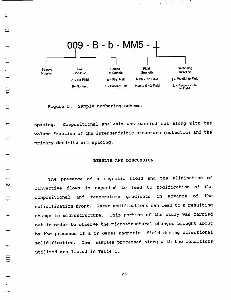
shown in Figure 4. The numbering scheme is explained in Figure 5.
The first set of measurements were taken over a section 3 cm in
length with measurements at every 0.5 cm. Measurements were also
taken at different radial positions including the center of the
sample and 2 mm in from each edge. Parameters measured included
volume fraction of the carbides, and secondary dendrite arm
22
mF_
m ISampleNumber
009 - B - b- MM5I I LField Portion
Condition of ..%mple
• = FirstHalf
b = SecondHalf
A = No Field
B= No Field
L__! i IField Sectioning
Strength Direction
MM0 = No Field I = Parallel to Field
MM5 = 5 kG Field .L = Perpendicularto Field
Figure 5. Sample numbering scheme.
spacing. Compositional analysis was carried out along with the
volume fraction of the interdendritic structure (eutectic) and the
primary dendrite arm spacing.
RESULTS AND DISCUSSION
The presence of a magnetic field and the elimination of
convective flows is expected to lead to modification of the
compositional and temperature gradients in advance of the
solidification front. These modifications can lead to a resulting
change in microstructure. This portion of the study was carried
out in order to observe the microstructural changes brought about
by the presence of a 5K Gauss magnetic field during directional
solidification. The samples processed along with the conditions
utilized are listed in Table i.
23

....... ! . +
i
-row
_mr
Sample #
O01N4NO
0011,_45
002._
002814145
O03AMMO
003B_45
O04BMMO
O05AMHO
O05BMM5
0068MM5
0071_C
O08BMM5
O09AMMO
009BHM5
010BHM5
010AMMO
011BMM5
011AHMO
DateProcessed
12/16/85
12118185
12117/85
12124/85
12117185
12123185
01106186
02106/86
02107186
02110/86
02110186
02/13186
02119186
07122186
O7124186
O7124/86
07125186
08113186
08115166
Table 1. SampLe Identification Numbers _d Processing Conditions
FurnaceTranslation Field
Rate (KG)
1 crdmin 0
1 cnVmin 5
1 cm/min 0
1 ce_'m|n 5
1 c_@min 0
1 caVmin 5
1 cm/min 5
I cm/min 0
1 cnVmin 5
1 cm/min 0
1 ca/mr n 5
1 cm/min cycled5130 sec0/60 sec
1 ca/m| n 5
1 cm/mi n 0
1 cm/min 5
1 cm/min 5
1 cm/min 0
1 cm/min S
1 cm/mTn 0
Comments
Soak at 1227"C 30 min. Top U to field, bottom cut z,
Soak at 1227"C ]4) m|n, Top ]1 to field; orientation ofbottom Lost.
Soak at 1227°C 40 min. Top _ to "fieid," bottom cut IJ-
Sample was remalted end processed after one hour soakfoLLouing two failed attempts.
Orientation |oat.
Soak at 1227=C one hour.
Note crucible not baked out.
Sample has large void at bottom approx, lmm blowholeis|de) all along Length ('45 min. soak)•
30 mln. soak. Crucible stuck in furnace duringtranslation; broke (spec|men tube shattered).
Argon disconnected at bottle after purge. Nuchoxidation. 15min• aoak;bott_didnot f|ow. BLowhole.
Argon d_scorv_ectedetbottte after purge. 15 min. soak.Nore "unf[owed" at top than O05AHHO.
1/2 hr. purge; not disconnected; 1 hr. soak. Used4.sample. 42mm flowed, 30 mm retained oxide skin. Noho[es visible.
1hr. purge, 1 1/2 hr. soak. Periodicboutsof vibrationcaused assembly to "jump."
Nagnet balking, 1/2 hr. soak, sandblasted to removeoxide.
112 hr. soak; sandblasted magnet working.
SandbLasted; 45 min, soak, magnet cut-off in last .2 cmof run.
Sandblasted, 45 min. soak.
Sandblasted, 30 min. soak, furnace position Lower 9.0magnet cut-off at 2.5. (<6.5 - soLidification complete).
Sandb(asted, 30 mtn.

w
Stereological Measurements
Carbide Volume Fraction
A comparison of the volume fraction of carbide phase between
a MAR-M 246 + Hf sample solidified under no magnetic field (Sample
003AMMO) and under a 5 KG (Sample 003BMMS) field are shown in
Figure 6. Both samples exhibit carbide volume fractions of roughly
4.0%. (No field, V v = 3.9%, 5KG, V v = 4.15%). Results obtained
for the no-field sample indicate roughly the same volume fraction
down the center of the sample as along the edges. However, in the
magnetic field solidified sample, the volume fraction of carbides
near the edges of the sample shows some tendency to move to higher
values than the center as solidification progresses. This
variation does not appear to be statistically significant since
subsequent samples have not shown the same trend.
w ¸
_z
=
25
i

w
w
L
,"Vv
vv
6.0
5.G
4.0
3.0
2.0
6.0
5.0
4.0
3.0
2.0
0 K6
CENTEREDGE
EDGE
2_5 ..... ""7.5 .,2.5 .17.5 22.5 27.5
MM
5 KG
- CEI_TER
EDGE
EDGE
m
7.s 12,5 17.s 22'.5 2;,sMM
LONGITUDINAL VARIATION IN CARBIDE Vv
003AMM0
003BMM5
Figure 6. Comparison between the volume fraction of carbides
in samples directionally solidified with no magnetic field (Sample
003AMMO) and with a 5 KG magnetic field (Sample 003BMMS).
Measurements were made down the center of each sample and 2 mm in
from each edge. Distances are measured from the start of
solidification. Solidification rate 1 cm/min.
26

=
=
- m
In general, little difference was found between the average
morphological parameters of the magnetic field solidified samples
and those solidified without a magnetic field. The main
differences appeared to be one of uniformity, with the no-field
samples being uniform while a variation was obvious between the
center and edges of the field-solidified sample.
This difference may arise due to the convective damping
present in the field solidified samples. Moderate convection,
which is likely for the no-field samples, would tend to homogenize
the liquid in advance of the solidification front. On the other
hand, if convection were slowed drastically but not stopped, a slow
convective roll, in conjunction with solute rejection at the
interface, could lead to compositional differences between the
center and edges of the sample. This could lead to radial
variations in the carbide volume fraction and morphology.
Volume Traction of the Interdendritic Eutecti9
One factor which may effect the performance of a superalloy
is the volume fraction of the interdendritic eutectic constituent.
A detailed stereological analysis was carried out in this project
in order to determine any variation in the volume fraction of the
eutectic constituent with the magnetic field. The samples
analysed, along with the results obtained are given in Table 2.
Measurements were made until a C.V. of 5% or less was obtained.
With one exception, the volume fractions of the eutectic
27

w
T
Tabte 2. Votume Fraction of the lntendendritic Eutecti¢ Constituent
Naonet|¢ FieLd SampLe Number Vv(%) - 95% C.;. C.V. NumberStrength (KG) of Counts
0 O09AaI_NO 14.65 * 1.46 0.0495 1792
0 O09Able40 9.55 _ 0.96 0.0498 2480
0 011At_1140_ 17.68, 1.76 0.0498 1536
5 O03SHH5 17.47 i 1.72 0.0490 1408
5 O09Bb14H511 14.45 , 1.44 0.0497 1792
5 011Ba1_5_ 16.39 t 1.62 0.0493 1600
5 011B1:_45_ 14.90 _ 1.50 0.0504 1728
5 ?n?_?.5[I 15.8o t 1.55 o.o5oo 153o
constituent in all samples were approximately the same. Sample
009A6MM0 which was the top half of a sample processed under no-
field conditions contained a significantly lower volume fraction
of the interdendritic eutectic constituents than any of the other
samples. There is no obvious reason for this lower volume
fraction. The lower portion of this same sample, 009AaMMO, yielded
a volume fraction of 14.65% which was more in line with the results
obtained in the other samples. The results obtained indicate that
a 5KG transverse magnetic field had no major influence on the
volume fraction of the interdendritic constituent in this study.
28

w
w
w
m
DAS
(x 103 cM)
4.0
3.5
3.0
KG
0 K£
2.5 , , , - ' '2.5 7.5 12.5 17 ,5 22.5 2.7,5
MM
SECONDARY DENDRITE A_i SPACING
LONGITUDINAL
Figure 7. Secondary dendrite arm spacing as a function ofamount solidified in a no-field sample 003AMMO and a 5KG solidified
sample 003BMMS.
Secondary Dendrite Arm Spacinq
Measurement of the secondary dendrite arm spacing as a
function of distance yielded a relatively uniform spacing along the
length of the no-field sample and a slight reduction in spacing
with amount solidified in the 5 KG sample. These results are shown
in Figure 7. The differences between the two samples cannot be
considered statistically significant.
29

_L
Table 3. Primary Dendrite Arm Spacing
w
Magnetic Field
Strength (KG)
Sample Number Primary Dendrite Spacing
0 009AbMMO 0.1303
0 011AbMMO± 0.1649
5 009BbMM5 0.1300
5 011BaMM51 0.1576
5 011BbMM51 0.1311
5 ??????M5 0.1558
Primary Dendrit@ Arm Spacing
Transverse sections were taken of several of the samples
processed in this study in order to permit measurement of the
primary dendrite arm spacing. The samples analyzed and the
corresponding results are given in Table 3.
From Table 3 the primary dendrite arm spacing seems to fall
into two groups. One group of samples all have primary dendrite
arm spacings of approximately 0.13mm. The remaining samples have
primary dendrite arm spacings centered around 0.16mm.
Unfortunately, there appears to be no correlation between the
presence of a magnetic field and the primary dendrite arm spacing
in this study. A higher field strength, different growth
conditions or a different field orientation may yield different
results.
w
=w
3O

w
L
u
p_
Chemical Analysls
In addition to morphological changes in samples solidified
under a magnetic field, it is also quite possible that
compositional changes will occur. A qualitative analysis was
carried out early in this project using a scanning electron
microscope (SEM) and energy dispersive x-ray analysis system to
roughly determine the difference in carbide compositions between
a no-field (Sample 006AMMO) and a 5KG (Sample 006BMMS) solidified
sample. In this analysis carbides in the upper 1 cm of the no-
field and 5 KG field samples were selected at random and analyzed.
Results for each sample were averaged and raw peak heights (counts)
were used to compare the relative differences in composition of the
carbides in the two samples. The results are shown in Figure 8.
In this figure, the average counts found for a selected
characteristic x-ray peak for a particular element was used as the
control value. The average counts obtained from the 5 KG
solidified sample were then compared to those obtained for the
control. The percentage of tantalum (Ta), titanium (Ti), and
tungsten (W) in the carbides were all lower in the 5 KG sample than
in the no field sample, while the percentage of hafnium (Hf) was
considerably higher.
It was felt that a more detailed compositional analysis was
justified. During the later stages of the project two no-field
MAR-M 246 + Hf samples (009AMMO, 011AMMO) and two 5 KG field
samples (009BMM5, 011BMM5) were analyzed for carbide, dendrite,
31

CARBIDE COMPOSITION
EDAX Analysisof Carbides in Specimens
Solidified in 0 KG and 5 KG Magnetic Field
w
u
w
175
U (:},.- (J
I_. e- 125E
il_ .m
W 100_.- Q."" c_0
L 0
E o7"
0
n
J
I!
I0 50 5 0 5
T,a Ti W HF
r
r
Figure 8. Comparison of carbide compositions between no-
field (Sample 006AMM0) and 5KG field solidified (Sample O06BMM5)
MAR-M 246 + Hf superalloys. For each element, the average
characteristic x-ray peak intensity for the no-field sample was
normalized to 100% to facilitate comparison with the 5 KG field
sample.
interdendritic, and eutectic composition using a Cameca-SX50
microprobe and wavelength dispersive x-ray spectroscopy. Both the
eutectic and dendritic regions were analyzed using the area mode.
Since the interdendritic regions contained several distinct phases,
these areas were analyzed using the spot mode.
32

TabLe 4. Compal'tson of Carbide Compositions for FieLd end No-FieLd SampLes
ELement (X)
Magnetic SampLe Cr Co Ti At 14o g Hf Ta Ni Type I .D.Irletd Strength Number
(KG)
+
0 011Aml_O_ 2.17 1.34
0 011AalelO. 19.82 2.66
0 011AaM_± 2.55 4.39 1.98 1.41
0 011A1:_10_ 4.54 3.92 7.06 1.98
0 011A1:_10_ 3.17 6.50 0.40 0.92
0 011AI:_40_ 1.42 1.21 14.14 0.06
0 009AI_40_ 2.18 2.58 I. 52 O. 88
5KG oo98 511l.m lOl 15.41 ooo
5 KG 011BaletS.L 1.01 0.64 23.21 0.00
5 KG 011Ba_5_ 1.17 1.49 14.13 0.00
009, 5111.64 0.92 27.400.075 KG 011ab_5.L 1.48 0.79 36.19 0.19
5 KG 011BbteqS.L 2.98 2.52 11.99 0.45
13.61 0.15 7.04 28.26 11.32 30.28
0.48 0.22 23.68 42.84 0.59 0.68
5.84 2 D3
9.03 ? D4
1.47 7.51 44.21 5.96 30.56 1 D5
5.67 16.92 20.85 18.01 21.03 ? E3
0.81 0.05 38.21 1.92 48.02 I 24
6.58 24.40 17.86 28.91 6.14 2 E5
1.02 7.87 61.06 8.41 14.47 1 A4
7.34 27.32 12.77 28.91 5.42 2 B4
3.86 23.99 11.68 32.58 3.01 3 F3
4.33 25.30 6.60 1.55 45.43 ? F4
4.34 20.05 13.42 23.30 8.87 3 C4
2.22 16.52 14.35 24.80 3.47 3 G3
6.68 25.94 12.14 24.46 12.85 2 G4
-- +.
Results obtained from the microprobe analysis of the carbides
in all samples are presented in Table 4. Backscattered electron
images which show the actual positions analyzed in the micropobe
and the sample identification numbers are included in the Appendix.
The I.D. code listed for each carbide indicates the figure and spot
number in the photomicrograph included in the Appendix.
While many additional carbides would have to be analyzed to
establish a significant pattern, it appears that at least three
types of carbides are present based on their compositions. For
example, three of the thirteen carbides all have Hf levels above
33

z
approximately 40% while having Ta and W levels below 9%. These
three carbides are labeled type 1 in Table 4. It is interesting
that all three of these carbides were found in samples solidified
with no applied magnetic field.
Another group of carbides that appear to have roughly equal
compositions contain between 12 and 16% Ta, 24 to 29% W, ii to 19%
Hf, and 28 to 31% Ta. These four carbides are listed as type 2 in
Table 4 and were found in both the field and no-field samples.
Three of these were blocky carbides while the fourth appeared to
be a script carbide plate. The fact that these carbides were found
in both types of samples implies their formation is not influenced
by the presence of a magnetic field.
In another grouping, three similar carbides were found which
had high Ti concentrations (above 23%) combined with low Cr and Co
contents (approaching I%). These carbides are labeled as type 3
in Table 4. All three of these carbides were found in samples
solidified under a magnetic field.
While these results are not statistically sound, they do
indicate a possible trend with high Hf-content carbides being more
likely in no-field samples and high Ti-content carbides being more
likely in magnetic-field-solidified samples.
Compositional analysis was also carried out on the dendrites
in both the no-field and field solidified samples. Results are
presented in Table 5. From the data gathered there appears to be
no appreciable difference between the composition of dendrites
34

s
;,_,-
----_
TabLe 5. Dendrtte Ccumqpos|tionfor FieLd _ No-F|etd Sot|d{f|ed SampLes
Magnet | c Sampt•FieLd Strength Number
(KG) Cr
0 011A#tNOz 9.42
0 011Ab_qOz 8.49
0 O09AbO4NO 8.85
, 9535 011Bai,_5± 8.34
, 8.5 0118bM_45_ 9.09
Element
| ,D.
Co Ti AL No W Hf Ta Nt (see text)
10.64 0.86 5.85 2.03 10.40 0.35 0.95 58.51 02
10.95 0.89 5.72 2.05 110.01 0.22 0.92 60.77 E2
11.15 0.74 5.49 2.13 10.66 0.220 0.80 59.98 A1
11.34 0.76 5.26 1.90 10,18 0.10 0.76 61.16 81
11.12 0.80 5.53 2.07 10.8/+ 0.25 0.76 60.29 F2
10.55 0.82 5.95 2.06 10.03 0.41 0.73 61.37 (::1
10.85 0.87 5.89 2.10 9.11 0.33 0.78 600.98 G2
TabLe 6. Composition of the Interdentritic Eutectic Constituent F!etd vs No-FieLd SampLes
ELement Z
Nagnet!cFieLd Strength
(KG)
SampLeNumber Z.D.
Cr Co T| At No Q Hf Te Ni (see text)
0 011Aa/e40z 8.11 8.69 1.50 6.59 2.37 5.70 4.51 1.22 61.30 D1
0 011A1_0± 9.03 9.26 i.45 5.92 2.86 5.38 2.59 1.12 62.38 E1
0 O09AbNMO 10.14 10.30 1.22 5.88 3.02 7.18 1.85 0.78 59.61 A2
5 0098a_5 H 9.51 10.32 1.32 5.69 2.92 7.51 1.65 0.61 60.47 B3
5 011BaMMSz 9.52 9.93 1.46 6.24 3.21 6.47 2.49 0.82 59.85 FI
5 O09B/:_lM511 8.87 9.87 1.30 6.27 3.28 7.89 1.64 0.89 59.99 C2
5 011BIoMMS± 9.77 9.61 1.55 6.41 3.08 4.55 2.79 0.79 61.45 G1
formed during solidification under no-field conditions and those
formed during solidification under a 5 KG field.
The interdendritic eutectic constituent was also analyzed
using wavelength dispersive x-ray spectroscopy on the microprobe.
The results obtained are presented in Table 6. Again, no apparent
differences were found in the compositions of the eutectic
constituent between the no-field and 5 KG field solidified samples.
35

w
Solidification Under Cyclic Field Conditions
One Sample (007MMC) was processed in which the magnetic field
was applied intermittently in order to mimic the low-g, hlgh-g
periods of solidification obtained in experiments performed on
NASA's KC-135 zero-g aircraft. Since both a magnetic field and
microgravity conditions serve to reduce fluid flow during
solidification, it is often assumed that solidification under a
magnetic field will produce structures very similar to those
obtained during solidification under microgravity conditions.
While this may be justified as a first approximation, there are
important differences between the influence of these two conditions
on the solidification process.
A steady magnetic field during solidification slows all fluid
movement. This includes damping of gravity driven flows, surface
tension driven flows and any other flows. The situation is
different in the case of microgravity solidification. Here the
driving force for normal convection and sedimentation is removed.
However, it is important to note that fluid movement is not
restricted. Indeed it has been stated that flows of only minor
importance under l-g conditions, such as as surface tension induced
flows, may become dominate factors during solidification under
microgravity conditions.
While in depth, long duration microgravity studies must be
carried out in order to gain a true understanding of the
significance of these various flows on the solidification process
36

L
, s
and the resulting microstructural features, some insight can be
gained from a simple comparison of structures obtained from
experiments performed on the KC-135 and experiments carried out
using intermittent applications of a magnetic field. In KC-135
directlonal solidification studies on MAR-M 246+Hf alloys performed
by Johnston et al. I, samples were solidified during repetitive
exposure to approximately 30 seconds of low gravity followed by
approximately 45 seconds of high gravity (up to 1.8g). This was
carried out for several cycles. Johnston's results indicated a
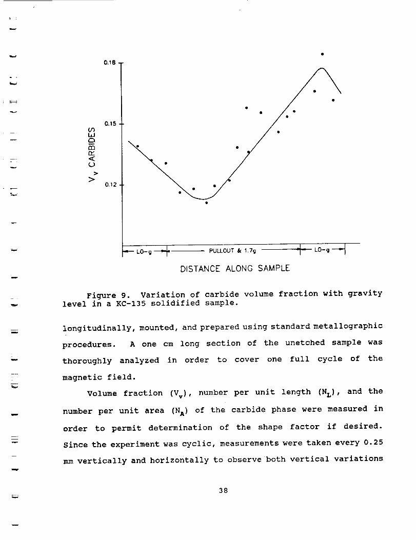
variation in the volume fraction of the carbide phase as shown in
Figure 9.
For comparison purposes, in the current study samples were
solidified while being subjected to a repetitive exposure of 30
seconds of applied field followed by 60 seconds of no field. While
this will not completely duplicate the environment experienced in
the KC-135, the results at least provide some means of
distinguishing between the influence of a magnetic field and the
influence of low-gravity conditions on the solidification process.
It must be remembered in the interpretation of these structures
that steady state conditions are probably not reached and that
comparisons are actually being made between transient structures.
MAR-M 246+Hf samples were directionally solidified at a rate
of 1 cm/minute and the magnetic field turned on for 30 seconds at
5000 Gauss, then off for 60 seconds. This was repeated throughout
solidification. The magnetic field was oriented horizontally and
a vertical growth direction was utilized. The sample was sectioned
37
E _
w
m
09I,IC_
C3
<
>
0.18
0.15
0.12
_1 PULLOUT & 1.7g "J-7-- LO-g
DISTANCE ALONG SAMPLE
LO-g
Figure 9. Variation of carbide volume fraction with gravity
level in a KC-135 solidified sample.
m
----
w
longitudinally, mounted, and prepared using standard metallographic
procedures. A one cm long section of the unetched sample was
thoroughly analyzed in order to cover one full cycle of the
magnetic field.
Volume fraction (Vv) , number per unit length (NL) , and the
number per unit area (NA) of the carbide phase were measured in
order to permit determination of the shape factor if desired.
Since the experiment was cyclic, measurements were taken every 0.25
mm vertically and horizontally to observe both vertical variations
38

Table 7. Carbide Volume Fraction (Vv) and Coefficients of
Variation for Intermittent Field Sample
w
Vert. Distance-mm
2.5
5.0
7.5
10.0
Left %
4.2
2.1
1.9
1.9
C.V,
1.3
3.1
3.9
1.8
Center %
4.0
3.3
3.8
2.8
C.V.
1.5
0.9
1.7
1.6
Right %
5.1
4.3
4.5
3.7
C°V.
0.9
1.2
1.2
1.4
m
and variations across the sample. Shape factors were then
calculated at positions of 2.5 mm, 5.0 mm, 7.5 m m, and 10.0 mm from
the starting position and were carried out for locations at the
left, center and right of the sample. A range of values of 0.75
mm above, below and around each interval point was incorporated
into the statistical results with placements made at every 0.25mm.
The results of the carbide volume fraction, Vv, number per
unit length, N L, and number per unit area, N A, calculations are
tabulated in Tables 7, 8 and 9. In addition, a graph of the
carbide volume fraction as a function of position on the sample is
shown in Figure 10. As noted in Tables 7, 8 and 9 the coefficients
of variation for each measurement are quite large as compared to
a more desirable value of 0.05. The large values result due to
globules of the carbides in the matrix. Even over the small range
of 0.75 mm, the data points varied widely. From statistical
39

Table 8. Carbide NumberPer Unit Length (NL) andCoefficients of Variation for Intermittent Field Sample
Vert. Distance-mm
2.5
5.0
7.5
10.0
Left (ram"I)
17.28
17.82
15.21
14.29
C.V, Center(mm -I)
0.1
0.1
0.2
0.1
0.i
0.I
0.i
0.I
17.89
16.90
14.90
17.00
C.V. Right(n_m "I}
17.67
19.00
15.70
16.20
CoY.
0.2
0.2
0.2
0.1
Table 9. Carbide Number Per Unlt Area (N^) and Coefficients
of Variation for Intermittent Field Sample
Vert. Distance-mm
2.5
5.0
7.5
10.0
Left(mm -2)
1.65 x 10
1.65 x 10
1.92 x 10
1.57 x 10
CoVo Center(mm "2)
2.08 x 10
1.86 x 10
2.41 x 10
1.84 x 10
C.V.
0.1
Right(mm -2)
1.93 x 10
2.17 x 10
1.93 x 10
2.02 x 10
C,V°
0.1
calculations, 500 to 1000 counts would be necessary to obtain a
coefficient of variation of 0.05 for each value of Vv, NL, and N A
measured. This was obviously impossible due to the limited area
over which counts could be taken.
40

w
>>
O
<OfU_
W
_JO>
WC3
CDQf<
5.00-
4.80
4.60
4.40
4.20
4.0O
3.80 -
3.60-
3.40
3.20
3.00
2.80
2.60
2.40
2.20
2.00
•- LEFT SIDE OF SAMPLE
•- CENTER OF SAMPLE
- IDE OF' SAMPLE
't I I I
2.50 5.00 7.50 10.00
VERTICAL SAMPLE DISTANCE (mr'n)
Figure I0.
on a sample
conditions.
Variation of carbide volume fraction with position
solidified under intermittent magnetic field
The variation in volume fraction of the carbide phase which
resulted due to the cyclic magnetic field should be compared to the
results obtained on KC-135 solidified samples as shown in Figure
I0. In an attempt to characterize the carbides by shape, the V,,
i
41

TABLE i0. CARBIDE SHAPE FACTORS FOR INTERMITTENT
FIELD SAMPLE
Vertical Distance
2.5
5.0
7.5
10.0
Left
0.91
1.94
1.36
1.45
Center
0.82
0.99
0.51
1.22
Right
0.67
0.82
0.60
0.75
NL, and NAvalues were used to determine the shape factor, F1, as
described by Fishmeister. 19 This shape factor is given by
F I = (2/3_) • (NL2/VvNA)
and has a value of one for spherical particles and increases with
increasing complexity of shape. Results are tabulated in Table I0
and are plotted in Figure ii.
Referring to Figure Ii, it is apparent that as the vertical
distance along the sample increases, the shape factors cycle. This
cyclic pattern should indicate that the carbide morphology changes
with position. However, the shape factor was expected to cycle in
such a way that it approached a small value close to one for the
blocky carbides and increased to a higher value as more script
carbides formed. The fact that values consideriderably less than
one were obtained for F I are questionable. In addition, the
variations observed appear to be primarily due to changes in the
volume fraction of the carbide phase. As discussed previously,
42

_4
-J
Z
c_
Z
>
>
II
C
EOF-
<b_
W
<fIO0
2.00-
1.90
1.80
1.70
1.60
1.50
1.40
1.30
1.20
1.10
1.00
0.90
0.80
0.70
0.60
0.50
i- LEFT SIDE OF SAMPLE
•- CENTER OF SAMPLE
•- RIGHT SIDE OF SAMPLE
2.50 5.00 7.50 10.00
VERTICAL SAMPLE DISTANCE (mm)
Figure 11. Variation in the shape factor, FI, of carbideparticles vs position for a sample solidified under intermittentmagnetic field conditions.
this shape factor does not appear to be an appropriate indication
of carbide particle shape for this investigation.
43

r
w
The cycling effect of the volume fraction of the carbide phase
could be explained by a dependence on the composition of the
solidifying liquid. In the absence of a magnetic field, when solute
is rejected into the liquid at the solid-llquld interface it can
be distributed by convective fluid flow resulting in a fairly
uniform composition across the sample. However, when a magnetic
field is applied to the system, the convective fluid flow is
damped. This results in a slower distribution of the rejected
solute in the liquid and an effective change in the solute field
adjacent to the interface. It's quite conceivable these changes
will result in modification of the volume fraction of carbides
formed.
The results of this analysis indicate that a variation in the
volume fraction of the carbide phase does occur when a magnetic
field is varied during directional solidification of MAR-M 246+Hf
alloys. However, dependence of the volume fraction of carbide on
the magnetic field should be investigated further. Microprobe
analysis should have been carried out to specifically investigate
the compositional variation across the sample. Unfortunately, with
several project directors, the necessary transfer of files and
other project materials has apparently resulted in this particular
sample (007MMC) being misplaced. Further analysis is not possible.
It should be pointed out that different conclusions may be reached
upon comparison of steady state magnetic field structures with
structures obtained from longer term microgravity solidification
studies carried out on the orbiter.
44

m
w
w
CONCLUSIONS
This project was designed to provide an analysis of the
effects of magnetic fields on microstructural features in
directionally solidified dendritic superalloys, with special
reference to the influence on carbide morphology. It was hoped that
script vs blocky carbide shapes could be distinguished using a
shape parameter. However, the inability to determine N v values
from NA measurements on a plane section through a convoluted
particle makes this approach inadequate. The nature of this
problem is such that an accurate characterization of script vs
blocky carbides may require the use of a three-dimensional
technique.
Serial sectioning would provide the best information on the
extent of carbide networking in script morphologies as opposed to
blocky. However, it may not be necessary to fully characterize
carbide shape in order to investigate the effect of shape on
material properties. It has been shown that properties in the cast
iron system are linearly related to graphite Sv values, and the
same may prove true for carbides in superalloys.
Furthermore, there are other approaches which provide useful
information toward crack propagation predictions. Curvature
measurements, which would give an indication of the degree of
"sharpness" at carbide edges, could be performed in two dimensions.
If evidence is found that cracks are propagated into the matrix at
sharp carbide edges, then this measurement may yield significant
45

w
h
information without resorting to a three-dimensional analysis.
The main thrust in this study was to determine the influence
of a magnetic field on the microstructures obtained in
directionally solidified Mar-M 246 + Hr. A steady magnetic field
of 5KG oriented transverse to the vertical growth direction
appeared to have little influence on the carbide volume fraction,
primary dendrite arm spacing and secondary dendrite arm spacing of
a sample directionally solidified at 1 cm/mm. However, it was
noted that samples solidified without a magnetic field appeared to
have a more uniform structure radially than those solidified with
a field. Coorelations could not be made between the volume
fraction of the interdentric eutectic constituent and the presence
of a magnetic field during solidification.
Chemical analysis indicated some differences between the
compositions of carbides formed during solidification with a
magnetic field and those formed without a field. It is conceivable
that a variation in carbide morphology could result due to these
compositional variations and could be used to advantage. No
significant trends were found in the variation of the composition
of the dendrites or of the interdendritic constituent with a
magnetic field.
The most dramatic variations in microstructure were observed
in a sample processed under cycled magnetic field conditions.
Here, changes in the volume fraction and shape factor were found
to occur as the field was cycled. While measurable variations were
observed, it must be remembered that the statistics of this portion
46
z
of the analysis are relatively poor due to a limited sampling area.
In addition, it is unlikely that steady state conditions were ever
reached during processing.
While the above study was comprehensive within its
constraints, additional work is considered desirable in order to
gain a more complete understanding of the possible influences of
magnetic fields on the solidification process. Higher magnetic
field strengths and difficult orientations may have significant
effects on the solidification process and the structures obtained.
Future work should be carried out to investigate the influence of
these variables.
w
47

r
L
F
l
ACKNOWLEDGEMENTS
The Principal Investigator would like to acknowledge the help
of Ms. Wendy Alter and Ms. Allison Sandlin who carried out much of
the sample preparation and quantitative metallographic analysis
reported in this study. Special thanks are due Ms. Dianne Schmidt
who has unselfishly participated in gathering and analyzing data
during the past few months. Completion of this project would not
have been possible without her help. Thanks are also due to Mr.
Steve Gentz whose comments, suggestions and assistance have played
a major role in meeting the science goals of this project. I would
also like to thank Dr. Mary Hellen McKay and the Marshall Space
Flight Center who thought this work was of sufficient interest to
provide funding for the project.
i
w
i
48
REFERENCES
u
w
lo
•
•
•
•
o
•
•
•
I0.
M. H. Johnston and P. A.
(1984).
Curreri, Personal Communication
Metals Handbook, Desk Edition, American Society for Metals,
Metals Park, Ohio (1984)•
11.
12.
13.
R. J. Naumann, "Microgravity Science and Applications
Program Description Document," NASA, Space Science Laboratory
(1984).
H.P. Utech, M. C.Flemings, "Thermal Convection in Metal-
Crystal Growth: Effect of a Magnetic Field," Supplement to
_ournal of Physics. Chem. of Solids, p. 651-658 (1966).
M. C. Flemings, Solidification Processing, McGraw Hill,
Inc., New York, New York (1974).
Metals Handbook, Ninth Edition, Volume 3, Properties andSelection: Stainless Steels, Tool Materials and Special-
Purpose Metals, American Society for Metals, Metals Park, Ohio
(1980).
S. R. Coriell, M. R. Cordes, W. J. Boettinger, R. F.
Sekerka, "Convective and Interfacial Instabilities DuringUnidirectional Solidificaiton of a Binary Alloy," J. of
Crystal Growth, Vol. 49, p. 13-28 (1980)•
T. G. Cowling, Magnetohydrodynamics,
Publishers, Inc., New York, New York (1957).
Interscience
S. Chandrasekhar, Hydrodynamic and Hydromagnetic Stability,
Oxford University Press, London (1961).
H. P. Utech, M. C. Flemings, "Elimination of Solute Banding
in Indium Antimonide Crystals by Growth in a Magnetic Field,"
J. of Applied Physics, Vol. 37, No. 5, p. 2021-2024 (1966)•
H. A. Chedzey, D. T. J. Hurle, "Avoidance of Growth-Striae
Semiconductor and Metal CrystalsGrown by Zone-Melting
Techniques," Nature, Vol. 210, p. 933-934 (1966)•
H. P. Utech, W. S. Brower, J. G. Early, "Thermal Convection
and Crystal Growth in Horizontal Boats: Flow Pattern, Velocity
Measurement, and Solute Distribution," Supplement to J. of
Physics, Chem. of Solids, p. 201-205 (1966).
S. Sanghamitra, W. R.Wilcox, "Non-Constant DistributionCoefficients for Directionally Solidified InSb-GaSb," Mat.
_es. B_II., Vol. 13, p. 293-302 (1978)•
49

14.
15.
16.
17.
18.
19.
P. R. Sahm, "Modified Microstructure in Eutectic Au-Co Alloys
by Use of a Magnetic Field During Directional Solidification,"
J. of Crystal Growth, Vol. 6, p. 101-103 (1969).
P. R. Sahm, H. R. Killias, "Directional Solidification of
Eutectlc and Off-Eutectic Au-Co Composites With and Without
Magnetic Field," J. Mat, Sci., Vol. 5, No. 12, p. 1027-1037
(197o).
J. D. Verhoeven, D. D. Pearson, "The Effect of a Magnetic
Field Upon Directional Solidification of Sn-Cd and Sn-Pb
Alloys," J .....of Mat Sci , Vol 8, p 1409-1412 (1973).
Y. Aoki, S. Hayashi, H. Komatsu, "Directional Solidification
of Aluminum-Silicon Eutectic Alloy in a Magnetic Field," J.
of Crystal Growth, Vol. 62, p. 207-209 (1983).
E. E. Underwood, Quantitative Stereology, Addison-Wesley
Publishing Co., Reading, Massachusetts (1970).
H. F. Fischmeister, "Shape Factors in Quantitative
Microscopy," Z. Metal_kde, Vol. 65, p. 558-562 (1974).
m
w
m
w
5O

L
_ +
APPENDIX - Microprobe Analysis Areas
Backscattered electron images of areas analyzed using the
Cameco SXS0 microprobe and wavelength dispersive x-ray spectroscopy
are shown on the following pages.
w
m
=
51

ORIGINAL PAGE IS
OF pOORQu ITY
Figure A. Photomicrograph of a MAR-M 246 + Hf sample
directionally solidified at 1 cm/min without a magnetic field.
Sample 009AbMMO. Photo was taken from the upper portion of the
sample (i.e., last to solidify). Backscattered electron image.
w
w
w
Figure B. Photomicrograph of a MAR-M 246 + Hf samplesolidified at 1 cm/min under a 5 K Gauss magnetic field. Sample
009BaMM5. Sample was sectioned parallel to the field direction.
Photo is from lower portion of sample (i.e., first to solidify).
52

ORIGINAL PAGE IS
OF POORqu J.n'Y
--_,_:
Figure C. Photomicrograph of a MAR-M 246 + Hf sampledirectional solidified at 1 cm/min under a 5 K Gauss magnetic field
(Sample 009BbMM5 ). Sample was sectioned parallel to the fielddirection. Photo was taken from top half of sample shown in Fig.
B. Backscattered electron image.
w
Figure D. Photomicrograph of a MAR-M 246 + Hf sample
directionally solidified at 1 cm/sec under no magnetic field
(Sample 011AaMM0). Photo is from the lower half of the sample.
53

Figure E. Photomicrograph of a MAR-M 246 + Hf sample
directionally solidified at 1 cm/min with no magnetic field
(Sample 011AbMM0). Photo is from the upper half of the sample in
Figure D. Backscattered electron image.
Figure F. Photomicrograph of a MAR-M 246 + Hf sample
directionally solidified at 1 cm/min under a 5 K Gauss magnetic
field (Sample 011BaMMS). Sample was sectioned perpendicular to the
field orientation. Photomicrograph is from lower portion of the
sample. Backscattered electron image.
54

= =
ORIG;/AL PAGE IS
r_i
w
Figure G. Photomicrograph of a MAR-M 246 + Hf sample
directionally solidified at 1 cm/min under a 5 K Gauss magnetic
field (Sample 011BbMM5). Sample was sectioned perpendicular to thefield orientation. Photo micrograph is from upper portion of
sample in Figure F. Backscattered electron image.
I
55
L k