influence of heat treatments on microstructure, … of heat treatments on microstructure, mechanical...
TRANSCRIPT

INFLUENCE OF HEAT TREATMENTS ON MICROSTRUCTURE, MECHANICAL
PROPERTIES AND CORROSION BEHAVIOUR OF ALLOY 625 FORGED ROD
Chantal Vernot-Loier , Francois Cortial
DCN Indret, Laboratoire d'Etudes et de Controle des Materiaux
44 620 La Montagne, FRANCE
Abstract
Influence of heat treatments between 500 and 1125°C on forged alloy 625 has been studied. Hardening between 650 and 800°C results of dislocation glidings of matrix, zf" precipitation and maximum of intergranular precipitation of fine M23C6 carbides. Tensile strength and intergranular corrosion through ASTM G 28 test become maxima, impact strength and reduction of area become minima, in the field of M23C6 and M6C intergranular precipitation : between 700 and 950°C.
Superalloys 718, 625 and Various Derivatives Edited by Edward A. Lmia
The Minerals, Metals & Materials Society, 1991
409
Introduction
Nickel alloy 625, typically containing 22 wt.% Cr, 9 wt.% MO, 3,7 wt.% Nb and < 5 wt.% Fe combine good mechanical properties, weldability and corro&on resistance (1). It has numerous applications in chemistry, pulp and paper (21, offshore and marine industries (3), and in geothermal power systems (4).
Alloy 625 is an interesting alloy for our applications, because it may be used to join by welding dissimilar metals such as low alloy steels, High Strength Low Alloy steels with alloy 625, to repair these steels by welding (5-7) or to clad them to protect against corrosion (8-10). In such cases, post-welding heat treatments may be necessary to keep good properties in the heat affected zone of the ferritic steels. But there are few results (11-13) on the influence of heat treatments on the structure and properties of alloy 625.
The stiffening effect of molybdenum and niobium on the nickel-chromium matrix is responsible for strength and two types of solution treatments could be chosen :
- between 930 and 1040°C to improve tensile strength and corrosion resistance, - between 1090 and 1200°C to improve creep resistance.
Intermetallic compounds and different sorts of carbides are able to precipitate in the face centered cubic matrix and in the grain and twin boundaries during further heat treatments. Thus, a precise study of heat treatments between 500 and 1125°C is necessary.
The purpose of the work reported in this paper was to determine the relationship between heat treatments, structure, mechanical properties and corrosion resistance.
Tests
Material
A 150 mm x 20 mm forged rod was purchased. The alloy was vacuum remelted. Table I shows the chemical composition of the rod.
Table I Chemical composition of as-received forged rod
Elements C Si P S Al Ti Fe Nb
wt 8 0,019 0,15 0,008 0,001 0.2 0,26 3,7 3,4
~ 0,l 21,4 8.7 0,07 61,8
Table II shows the mechanical properties of the as-received material and after 1 h at 1125"C, then water-quenched. The structure obtained after this treatment is given in figure 1, with inclusions of carbides and carbonitrides of Nb and Ti and oxides inside the fee twinned grains. This high
410

temperature solution treatment was chosen to study a heat state similar of those of welded alloy 625 but with a chemical composition as homogeneous as possible, to avoid artefacts due to segregations. This is the reference state for our study.
Table II Mechanical characteristics of as-received rod and material solution-treated 1 h at 1125°C and water- quenched
solution-treated 336 768 lh- 1125°C and water-quenched 332 767
RA CVN energy (%I (J)
160 160 165
295 295 285
Figure 1 - Optical micrographs of sample solution-treated 1 h at 1125°C and water-quenched. a) general view - b) detail view.
Heat treatments
160 mm length pieces of rod were heat treated 8 h at temperatures spaced of 50°C between 500 and 105O"C, and also at 1125"C, with heating rate of 50"C/h and air cooling.
411

Sampling is shown in figure 2.
Figure 2 - Sampling.
Structural investigations
Optical microscopy . All the heat treated samples were examined by optical microscopy using natural light and Interferential Differential Contrast (IDC) techniques , which enhances morphological and topographical phases differences. The micrographic samples were mechanically polished with alumina, and then electrolytically etched in a bath containing chromic anhydrid 25g, acetic acid (d=1,05) 130 ml, distilled water 7 ml, with power supply: 7 V d.c., during 1 to 2 min. depending on heating state.
Scanning Electron Microscopy (SEM). Before and after corrosion tests, samples were examined by means of SEM JEOL 840 equipped with an inclined Energy-Dispersive X-ray Spectrometer (X-EDS) EDAX ECON 9100.
Scanning Transmisson Electron Microscopy (STEM). The microstructural study of the heat treated samples has been performed with a STEM JEOL 2000 FX equipped with a horizontal X-EDS microzhv TRACOR Northern. Cristallographic calculations were done with the EDPA program of TRACOR Northern. Bright Field (BF), Dark Field (DF), and Selected Area Diffraction (SAD) techniques have been used. Thin foils for STEM were cut with a coated diamond wire-saw, down to 0.1 mm thickness and then thinned in a twin-jet electropolisher under different conditions depending on heat treatment state (Table III).
Table III Twin-jet electropolishing conditions for thin foils.
Heat treatments Bath Temp. Time ("C) (s)
95 % acetic acid 500°C to 750°C + 5 % perchloric +3++15 40*200 40+60 20+120
acid
90 8 ethanol 8OO'C to 1125"~ + 10 % perchloric o-e+3 100+500 15-50 20-70
acid
412
Mechanical properties.
The same tests were performed after each heat treatment.
Hardness tests. The Vickers hardness was measured using 10 kgf and 30 kgf load, on microscopically polished samples.
Tensile tests. The Yield Strength (YS 0.2 % offset), the Ultimate Tensile Strength (UTS), the Elongation (EL) and the Reduction of Area (RA) were determined at room-temperature, on two specimens which gage length equals five diameters, and taken with their great axis parallel to the rod length.
CHARPY Impact strength test. CHARPY Impact strength test has been performed at room-temperature, on three V-notch specimens taken with their great axis parallel to the rod length.
After test, fracture surfaces were examined in SEM.
Intergranular corrosion test
ASTM G 28 intergranular corrosion tests were performed on two samples of 70 mm x 10 mm x 3 mm for each heat treatment, with their great axis parallel to the rod length. ASTM G 28 test conditions were strictly applied except'for two points :
- one of the large side of each sample was mechanically polished with Wm diamond, to make possible microscopical investigations after tests. The other sides were polished under water with P 120 paper. - some tests concerning the most sensitive samples were shortened to be able to examine the beginning of the attack and to avoid a Fe 3+ depletion in the solution : 6 to 70 h compared to 120 h for normal test time.
After test, the weight losses of samples were converted into corrosion rate in mm/year and corrosion features were observed in SEM.
Results
Structural changes
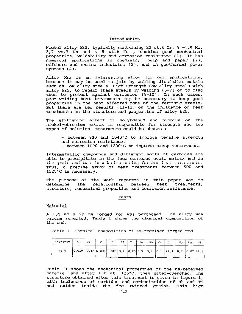
Structural changes are summarized in figure 3.
up to 65O"C, no structural difference exists between reference state (lh at 1125"C, water-quenched) and heat treated samples.
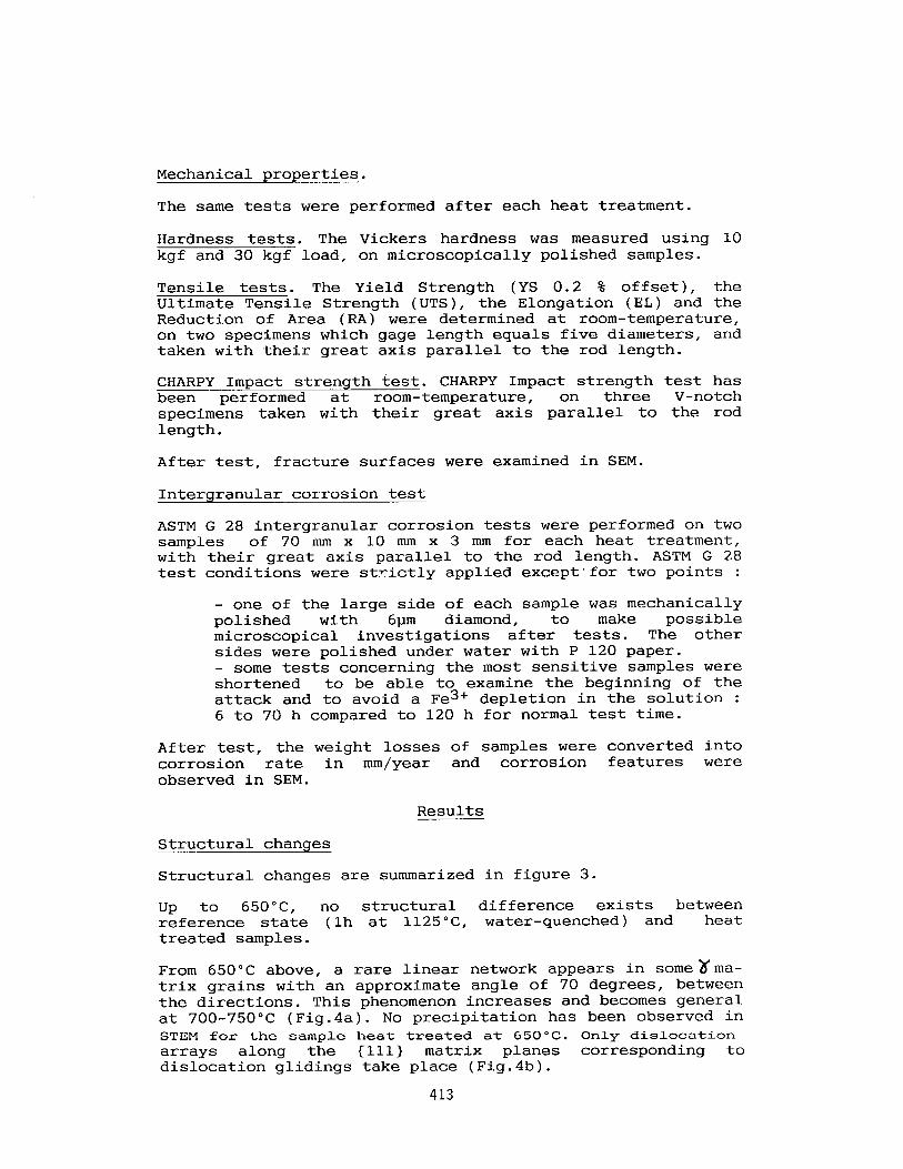
From 650°C above, a rare linear network appears in somexma- trix grains with an approximate angle of 70 degrees, between the directions. This phenomenon increases and becomes general at 700-750°C (Fig.4a). No precipitation has been observed in STEM for the sample heat treated at 650°C. Only dislocation arrays along the 1111) matrix planes corresponding to dislocation glidings take place (Fig.4b).
413
HEATING TEMPERATURE *c
A 1125 ..
lwo .
lay) _,
km0 . .
oy) . .
sm . .
es0 . .
sm . .
M . .
m . .
em . .
mo . .
550 . .
* - 10. m. .cr. SI
“23% CYMd.. I . cr.
no
n 4
a:,,* -
twtr’yor ml
Figure 3 - Phases stability of Inconel 625 heat treated.
*^a* _ .. * "4
if O.Olmm d* >’
a
Figure 4 - Optical and TEM micrographs of dislocation glidings of matrix. a) optical microscopy - b) transmission electron microscopy.
From 700°C above, this phenomenon increases and the If matrix present a speckled appearance due to the precipitation of the coherent intermetallic phase v W Ni3Nb tetragonal (Fig.5). At the same temperature, M23C6 (M = Cr, MO) fine carbides (x200 nm) precipitate at matrix grain boundaries (Fig.6). They are nucleated separately on both sides of grain boundaries with coherent boundary on its matrix side.
414

Figure 5 - Heat treated sample 8 h at 7OO"C, TEM examinations of the tetragonal intermetallic phase 8 "Ni3Nb. a) bright field - b) [OOl] '2/ SAD pattern.
-~~ic~h6i~F”ex r-i *-~-I~- ” vae- ‘XI w1 -_ I
CEL/CREF 1 .O”O 0 <:I27 0 .1099 0.174
ATOW EL UTX 82.16 77.01
2.08 2.08 ,.I& 7.54 7.80 13.36
1000 - I II .
if i
5 i
E I
500 +-
1 I4 C q
0 n
U.L 'E ':I4 M
I 0 H A 0
0 -L_ 15.000 20.000 6.000 5.000 10.000
c ENERGY keV
Figure 6 - Heat treated sample 8 h at 7OO"C, TEM examinations of intergranular M23C6 carbides. a) bright field - b) [OOl]r and M23C6 SAD pattern
of M23C6 carbide - c) typical X-EDS microanalysis.
415
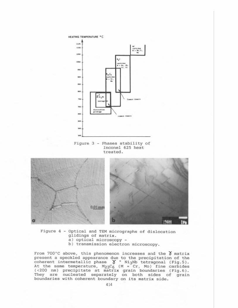
From 750°C above, the dislocation decreases and % It
glidings intensity particles are only segregated on matrix
dislocations (Fig.7).
Figure 7 - Heat treated sample 8 h at 75O"C, TEM examinations of
'I( V particles. a) bright field - b) corresponding
dark field - c) [OOl] 'd SAD
pattern used for dark field in b).
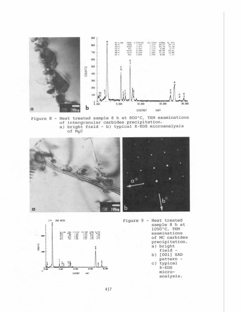
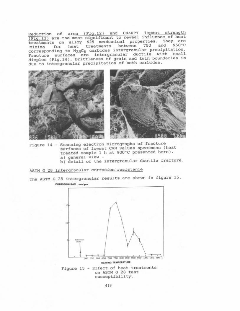
At 85OoC, dislocation glidings and* phase have disappeared. From 800°C above, the intergranular (grain and twin boundaries) precipitates are strongly associated and X-EDS microanalysis indicates a wide range of chemical compositions from Cr rich carbides to MO, Nb, Cr, Si rich carbides (Fig.8). At 9OO"C, M6C carbides coarsen and at lOOO"C, all M23C6 carbides have disappeared. Above lOOO"C, M6C carbides shorten in size and their number decreases whereas small MC carbides (M = Nb, Ti, MO) are observed at and near 3 matrix grain boundaries (Fig.9).
416
b ENERGY keV
Figure 8 - Heat treated sample 8 h at 8OO"C, TEM examinations of intergranular carbides precipitation. a) bright field - b) typical X-EDS microanalysis
of M&
LT- ZOO SECS Figure 9 - Heat treated w sample 8 h at 105O"C, TEM D_-LIIc *z I(-re.Tm "Us ;y EL-2 I .m
mm. O.m4 ES7 :z ,z 0.u ,":% I.90 ::z examinations ,I< mais 0.x, ,_a* 1.m s.a IC-K fz* 1.m 0.031 s.52 E.78 of MC carbides
F precipitation.
z w II ,a) bright
1 field -
b) [OOl] SAD II pattern -
c) typical X-EDS
ENEffiY keV micro- analysis.
417

Mechanical properties in relation to structural changes
Heat treatments influence the mechanical behaviour of alloy 625 in the range of 650-950°C.
Hardness (Fig.10) and tensile strength : YS(0.2%offset), UTS (Fig.11) increase for heat treatments between 650 and 800°C with the maximum hardening at 75O"C, corresponding to three microstructural events :
- dislocation gliding of I( matrix under influence of internal stresses before and during tetragonal '2( ' Ni3Nb precipitation, - tetragonal X 11 Ni3Nb precipitation, - M23C6 carbides formation at grain and twin boun- daries.
Figure 10 - Hardness curve VS Figure 11 - Tensile strength heat treatments. curves VS
heat treatments +UTS wo.2 % YS
Elongation does not vary significantly (Fig.12).
Figure 12 - Ductility curves heat treatments
* RA --
vs Figure 13 - Effect of heat treatments on CHARPY V-notch
Jt EL
4.18 impact strength
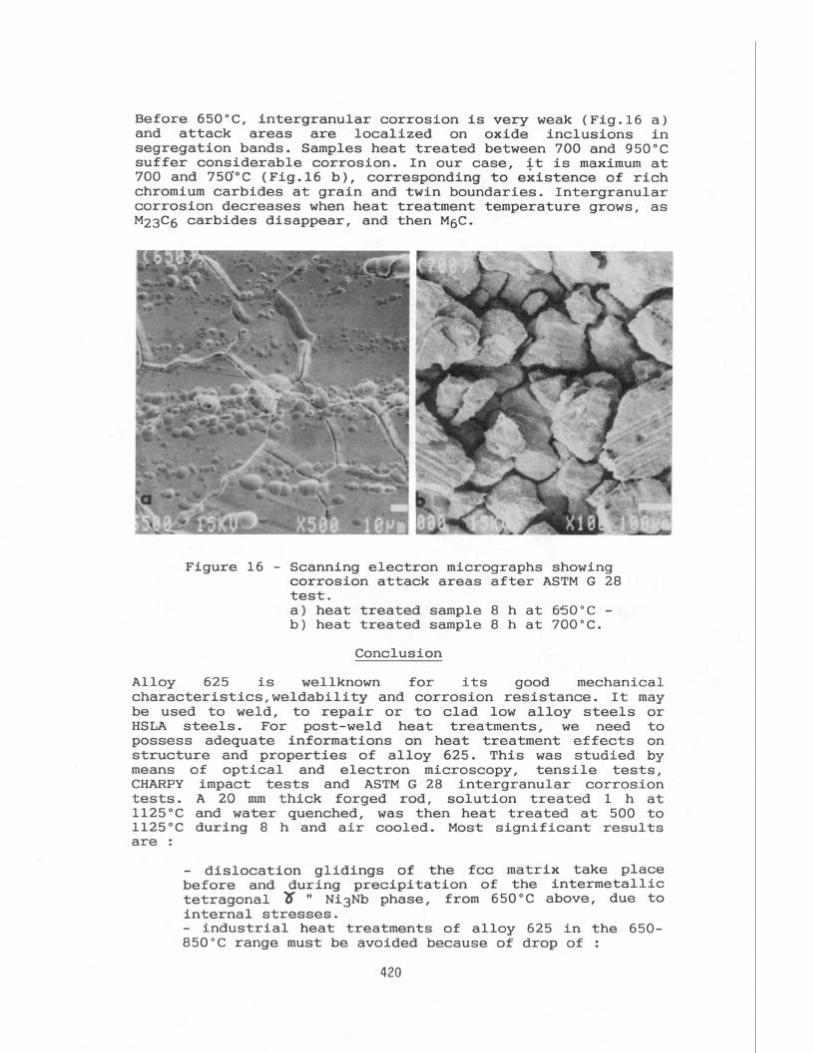
Reduction of area (Fig.12) and CHARPY impact strength (Fig.13) are the most significant t0 reveal influence Of heat
treatments on alloy 625 mechanical properties. They are minima for heat treatments between 750 and 950°C corresponding to M23C6 carbides intergranular precipitation. Fracture surfaces are intergranular ductile with small dimples (Fig.14). Brittleness of grain and twin boundaries is due to intergranular precipitation of both carbides.
Figure 14 - Scanning electron micrographs of fracture surfaces of lowest CVN values specimens (heat treated sample 1 h at 900°C presented here). a) general view - b) detail of the intergranular ductile fracture.
ASTM G 28 intergranular corrosion resistance
The ASTM G 28 intergranular results are shown in figure CORROSION RATE mm,ysa
15-
10-
*- Rere-* atate
I I : ” l
500 550 500 650 700 750 ““II 050 900 950 ,000 1050 1 ,ooOc
HEATING TEMPERATURE
15.
Figure 15 - Effect of heat treatments on ASTM G 28 test susceptibility.
419
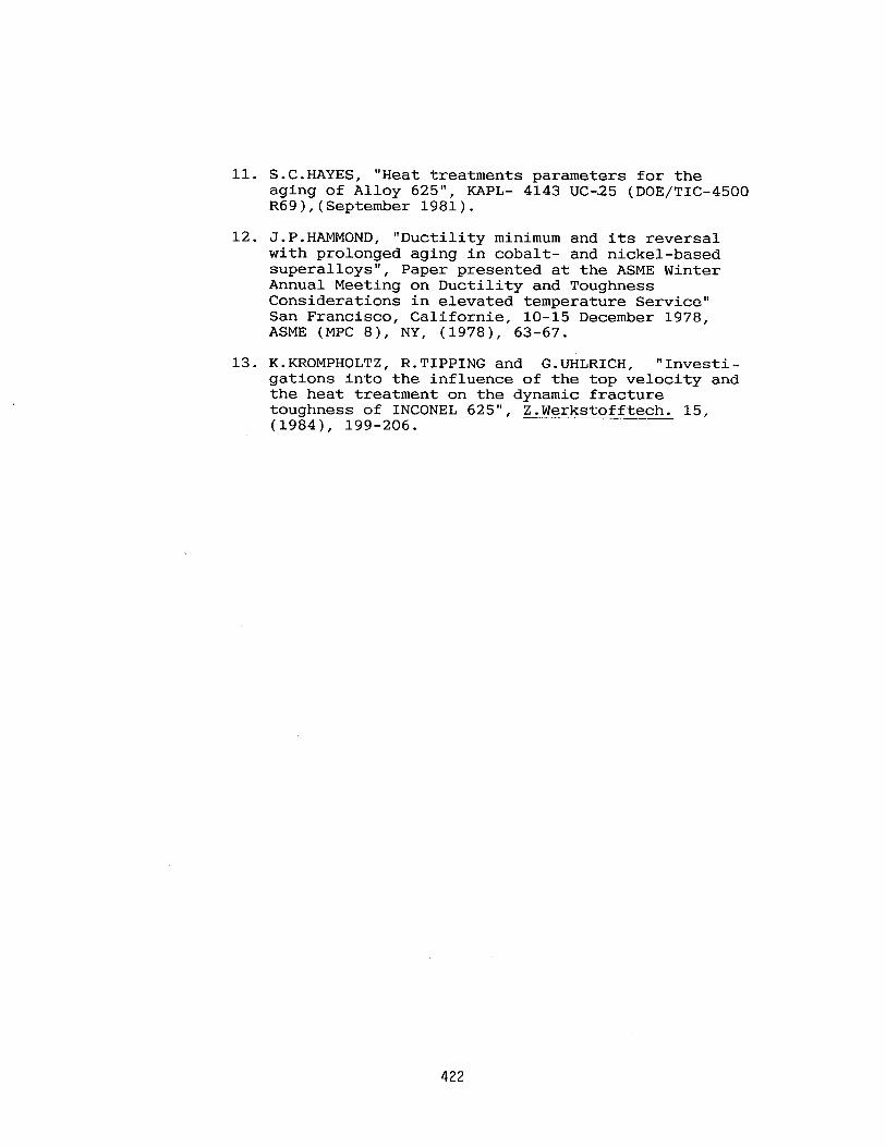
Before 65O"C, intergranular corrosion is very weak (Fig.16 a) and attack areas are localized on oxide inclusions in segregation bands. Samples heat treated between 700 and 950°C suffer considerable corrosion. In our case, it is maximum at 700 and 750°C (Fig.16 b), corresponding to existence of rich chromium carbides at grain and twin boundaries. Intergranular corrosion decreases when heat treatment temperature grows, as M23C6 carbides disappear, and then M6C.
Figure 16 - Scanning electron micrographs showing corrosion attack areas after ASTM G 28 test. a) heat treated sample 8 h at 650°C - b) heat treated sample 8 h at 700°C.
Conclusion
Alloy 625 is wellknown for its good mechanical characteristics,weldability and corrosion resistance. It may be used to weld, to repair or to clad low alloy steels or HSLA steels. For post-weld heat treatments, we need to possess adequate informations on heat treatment effects on structure and properties of alloy 625. This was studied by means of optical and electron microscopy, tensile tests, CHARPY impact tests and ASTM G 28 intergranular corrosion tests. A 20 mm thick forged rod, solution treated 1 h at 1125°C and water quenched, was then heat treated at 500 to 1125°C during 8 h and air cooled. Most significant results are :
- dislocation glidings of the fee matrix take place before and during precipitation of the intermetallic tetragonal 3 W Ni8Nb phase, from 650°C above, due to internal stresses. - industrial heat treatments of alloy 625 in the 650- 850°C range must be avoided because of drop of :
420

* reduction of area, * impact strength, * ASTM G 28 intergranular corrosion resistance,
all resulting from M23C6 and M6C rich chromium carbides precipitation at grain and twin boundaries.
Acknowledgments
The authors would like to thank greatfully Anne Poher for STEM investigations and Didier Lou&at for SEM investigations.
1.
2.
3.
4.
5.
6.
7.
8.
9.
10.
References
"INCONEL alloy 625" - HUNTINGTON Alloys Inc., Huntington, West Virginia, Publication no3700 - Revised (November 1981).
P.E.MANNING et al., "Evaluation of High Performance Alloys Used in the Pulp and Paper Industry", Materials Performance, (January 1984), 19-24.
"Marine applications for INCONEL alloy 625 weld overlaysn, Anti-corrosion, (February 1982), 10.
M.CONOVER, P.ELLIS and A.CURZON, "Material Selection Guidelines for Geothermal Power - An Overview", ASTM STP 717, ASTM,(1980), 24-40.
R.COX, "Refurbishing makes economic sense", Corrosion and maintenance, (April-June 1985), 97-98.
R.M.NUGENT, "Alloy 625 Surfacing tool and die steels", Welding Journal, (june 1986), 33-39.
T.J.GLOVER, Paper no16 presented at the 10th International Conference of the British Pump Manufacturers'Association, (Cambridge), Great-Britain 22-25 March 1987.
A.VAN BEST, Ph.DARGENT, "Electroslag cladding using nickel base alloys", Metal Constructions, (December 1983), 730-733.
C.E.STEVENS, R-ROSS Jr, "Production, Fabrication and Performances of Alloy 625 clad steel for agressive corrosive environments", J. of Materials for energy Systems, Vo1.8, n"1, (June 1986), 7-11.
P.KOSHY, "Alloy 625 weld cladding of wellheads and valves : Review of dilution control techniques and weld process development", Paper presented at the 17th Offshore Technology Conference, HOUSTON, (Texas), (06-09 may 1985), 145-153.
421
11. S.C.HAYES, "Heat treatments parameters for the aging of Alloy 625", KAPL- 4143 UC-25 (DOE/TIC-4500 R69),(September 1981).
12. J.P.HAMMOND, "Ductility minimum and its reversal with prolonged aging in cobalt- and nickel-based superalloys", Paper presented at the ASME Winter Annual Meeting on Ductility and Toughness Considerations in elevated temperature Service" San Francisco, Californie, lo-15 December 1978, ASME (MPC 8), NY, (1978), 63-67.
13. K.KROMPHOLTZ, R-TIPPING and G.UHLRICH, "Investi- gations into the influence of the top velocity and the heat treatment on the dynamic fracture toughness of INCONEL 625", Z.Werkstofftech. 15, (19841, 199-206.
422