influence of open cross-section shape on … · analysis; euronorm en 1993-1 ... the relevant...
TRANSCRIPT

BULETINUL INSTITUTULUI POLITEHNIC DIN IAŞI Publicat de
Universitatea Tehnică „Gheorghe Asachi” din Iaşi Tomul LIX (LXIII), Fasc. 1, 2013
Secţia CONSTRUCŢII. ARHITECTURĂ
INFLUENCE OF OPEN CROSS-SECTION SHAPE ON COMPRESSION MEMBERS BUCKLING RESISTANCE
BY
PETRU MOGA, ŞTEFAN GUŢIU and ALEXANDRA-DENISA DANCIU*
Technical University of Cluj-Napoca Faculty of Civil Engineering
Received: February 1, 2013 Accepted for publication: February 22, 2013
Abstract. The methodology designs of the uniform compression member
with open cross-section, according to EN 1993-1-1/2006. Eurocode 3: Design of steel structures, is briefly presented.
The influence of the open cross-section shape on the compression member buckling resistance for six constructive cross-section shapes is also numerically analysed.
Key words: buckling resistance; compression members; comparative analysis; Euronorm EN 1993-1-1: Design of steel structures.
1. Introduction
The imperfections have an important influence on the phenomenon of buckling, the behaviour of real steel structures being dependent of
a) geometrical imperfections, due to defects causing lack of straight-ness, unparallel flanges, asymmetry of cross-section, etc;
b) material imperfections, due to residual stresses (caused by the rolling or fabrication process) or material inelasticity;
c) deviation of applied load from idealized position due to imperfect connections, erection tolerances or lack of verticality of the member. *Corresponding author: e-mail: [email protected]
82 Petru Moga, Ştefan Guţiu and Alexandra-Denisa Danciu
European buckling curves include a generalized imperfection factor. For hot-rolled steel members, with the type of cross-sections commonly
used for compression members, the relevant buckling mode is generally flexural buckling; however, in some cases, torsional or flexural–torsional modes may govern and they must be investigated for all sections with small torsional resistance.
Concentrically loaded columns can buckle by flexure around one of the principal axes (classical buckling), twisting about the shear centre (torsional buckling) or a combination of both flexure and twisting (flexural–torsional buckling).
Torsional buckling can only occur if the shear centre and centroid coincide and the cross-section can rotate; this leads to a twisting of the member. Z-sections and I-sections with broad flanges can be subject to torsional buckling.
Symmetrical sections with axial load not in the plane of symmetry, and non-symmetrical sections such as C-sections, hats, equal-leg angles, T-sections and singly symmetrical I-sections, i.e. sections where the shear centre and the centroid do not coincide, must be checked for flexural–torsional buckling.
The analysis of torsional bucking is quite complex; the critical stress depends on the boundary conditions and it is very important to evaluate precisely the possibilities of rotation at the ends. The critical stress also depends on the torsional stiffness of the member and on the resistance to warping deformations provided by the member itself and by the restraints at its ends.
Where a Class 4 cross-section is subjected to an axial force, the buckling resistance evaluation of the compression member according to EC3 takes into account the effective cross-section area. In a more accurate calculation the additional bending moment determined by the possible shift of the centroid of the effective area relative to the centre of gravity of the gross section is also taken into consideration (SR EN 1993-1-1/2006; SR EN 1993-1-5/2006; ESDEP, 1994).
2. Buckling Resistance of Member
The design buckling resistance of a compression member should be
taken as
1.
eff
1
,for Class1, 2 and 3 cross-sections;
, for Class 4 cross-sections.
y
Mb Rd
y
M
Af
NA f
(1)
Bul. Inst. Polit. Iaşi, t. LIX (LXIII), f. 1, 2013 83
For uniform members in compression, the value of the reduction factor, , for the appropriate non-dimensional slenderness, should be determined from the relevant buckling curve according to relation
22
1
; 1 , (2)
where: 2
0.5 1 0.2 ; – is an imperfection factor;
cr
eff
cr
, for Class1, 2 and 3 cross-section;
, for Class 4 cross-sections.
y
y
AfN
A fN
(3)
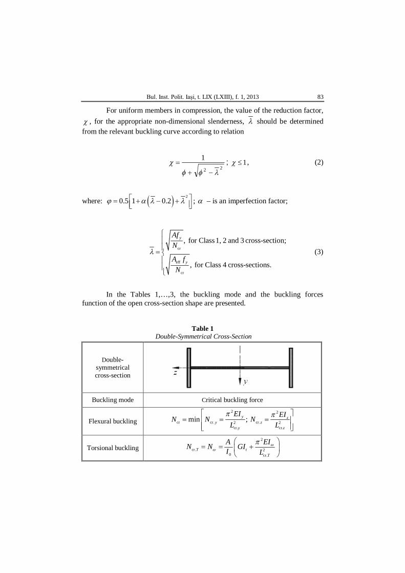
In the Tables 1,…,3, the buckling mode and the buckling forces
function of the open cross-section shape are presented.
Table 1 Double-Symmetrical Cross-Section
Double- symmetrical cross-section
Buckling mode Critical buckling force
Flexural buckling 2 2
cr cr. cr.2 2cr. cr.
min ; y zy z
y z
EI EIN N NL L
Torsional buckling cr.TN N2
20 cr.
tT
EIA GII L

84 Petru Moga, Ştefan Guţiu and Alexandra-Denisa Danciu
Table 2
Mono-Symmetrical Cross-Section
Mono- symmetrical cross-section
Buckling
mode Critical buckling force
Flexural buckling
2 2
cr cr. cr.2 2cr. cr.
min ; y zy z
y z
EI EIN N NL L
Torsional buckling cr.TN N
2
20 cr.
tT
EIA GII L
Flexural–torsional buckling
20cr. cr. cr. cr. cr. cr. cr.
0
( ) ( ) 42 ( )y z
TF z T z T z Ty z
I IIN N N N N N NI I I
Table 3 Non-Symmetrical Cross-Section
Non-simmetrical cross-section
Buckling mode Critical buckling force
Flexural–torsional buckling
2 2 20 cr. cr. cr.
2 2cr. cr 1 2 30, where min[ ; ; ]
y z c y
c z
f N i N N N N N N N z N N
N y N N N N N N
3. Numerical Analysis
The influence of the open cross-section shape on the values of the critical buckling force and of the buckling resistance of a compression member is analysed (Moga et al., 2011).

Bul. Inst. Polit. Iaşi, t. LIX (LXIII), f. 1, 2013 85
The following constructive solutions are discussed: Case 1: Non-symmetrical cross-section, with the flanges in opposite
position regarding the web. Case 2: Non-symmetrical U shape open cross-section. Case 3: Mono-symmetrical U shape open cross-section. Case 4: Mono-symmetrical double T shape cross-section. Case 5: Double-symmetrical double T shape cross-section. Case 6: Cross shape mono-symmetrical cross-section. In all cases the cross-section area has the same value and also the
dimensions of the web are preserved, respectively
2 2 2140 cm ; 500 10 mm 50 cm .wA A The following design data are presumed as being known: a) member cross-section; b) material: Steel S 355: 2355 N/mm ; 0.81yf ; c) buckling lengths:
L = 8.00 m; 5.0;1 zy ; cr. 8.0 my yL L ;
cr. cr. ( ) 4.0 mz zL L L .
3.1. Case 1: Non-Symmetrical Cross-Section, with the Flanges in Opposite Position Regarding the Web
The cross-section and the corresponding characteristics are presented in
Fig. 1.
Fig. 1 – Non-symmetrical cross-section, with the flanges in
opposite position regarding the web.
86 Petru Moga, Ştefan Guţiu and Alexandra-Denisa Danciu
a) Critical buckling force 2 2 6 4
2cr. 2 2
cr.
2 2 62
cr. 2 2.theor.
cr 2
2 20 cr.
2 6 66 2
2
2.1 10 7.833 10 10 25,341 kN;800
2.1 10 6,51810 8,435 kN;400
1
1 2.1 10 4.552 10 0.807 10 119 10737.23 400
yy
y
zz
cr z
t
EIN
L
EINL
NEIN GI
i L
9,293 kN,
where:
2 2 4 2 22 20
7.833 0.6518 10 140 5.4 10.1737.23 cm .140
y z s sI I A y zi A
For non-symmetrical cross-section, Ncr is obtained from eq.
2 2 20 cr. cr. cr.
2 2cr. 0.
y z s y
s z
f N i N N N N N N N z N N
N y N N
(4)
Using numerical values it results
737(N – 25,341) (N – 8,435) (N – 9,293) – N210.12(N – 25,341) –
– N25.42(N – 8,435) = 0 and consequently
cr 1 2 3min ; ; min 6,407 ; 13,619 ; 27,695 6,407 kN.N N N N .
b) Effective cross-section
TOP FLANGE EFFECTIVE AREA
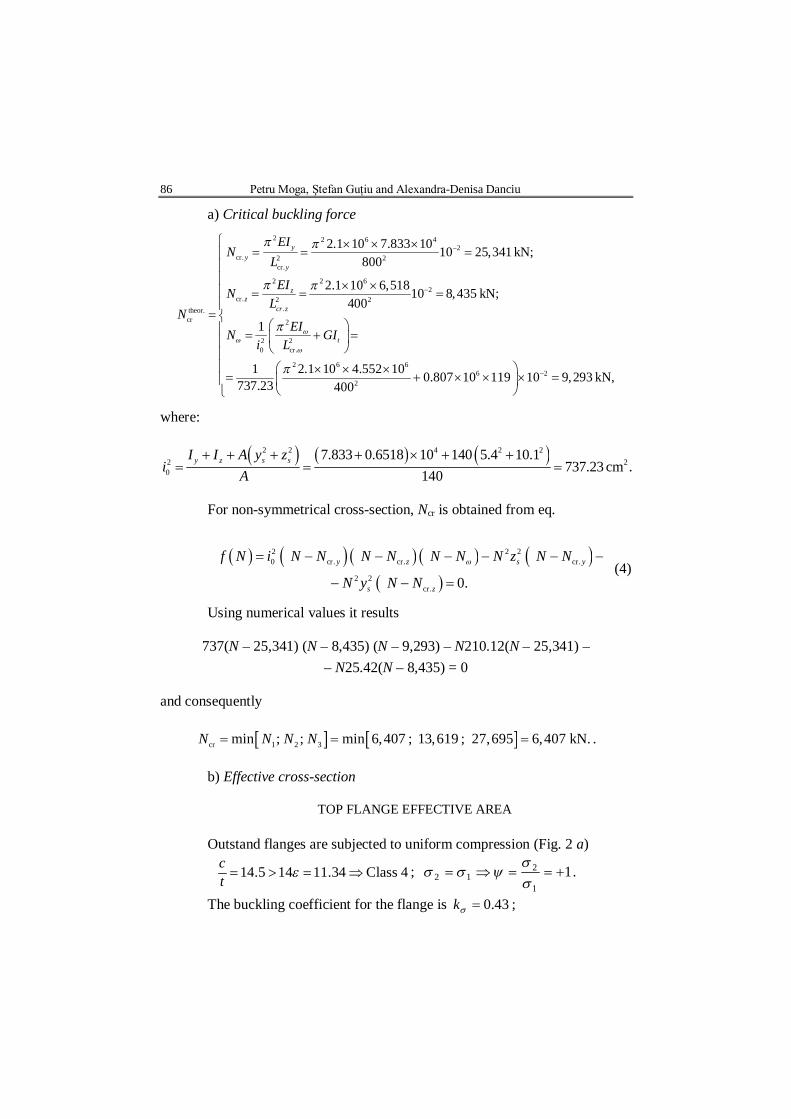
Outstand flanges are subjected to uniform compression (Fig. 2 a)
14.5 14 11.34 Class 4ct ; 1
1
212
.
The buckling coefficient for the flange is 43.0k ;
Bul. Inst. Polit. Iaşi, t. LIX (LXIII), f. 1, 2013 87
/ 290 / 20 0.96 0.74828.4 28.4 0.81 0.43
pp
b tk
.
It results
84.0188.02
p
p
.
a b
Fig. 2 – Compression in outstand flanges. The flange effective width is
eff 0.84 290 244 mmpb b .
BOTTOM FLANGE
Outstand flanges are subjected to uniform compression (Fig. 2 b)
12.67 14 11.34 Class 4ct ; 1
1
212
.
The buckling coefficient for the flange is 43.0k ;
/ 190 /15 0.84 0.748
28.4 28.4 0.81 0.43p
pb t
k
.
It results
92.0188.02
p
p
.
The flange effective width is
eff 0.92 190 175 mmpb b .
88 Petru Moga, Ştefan Guţiu and Alexandra-Denisa Danciu
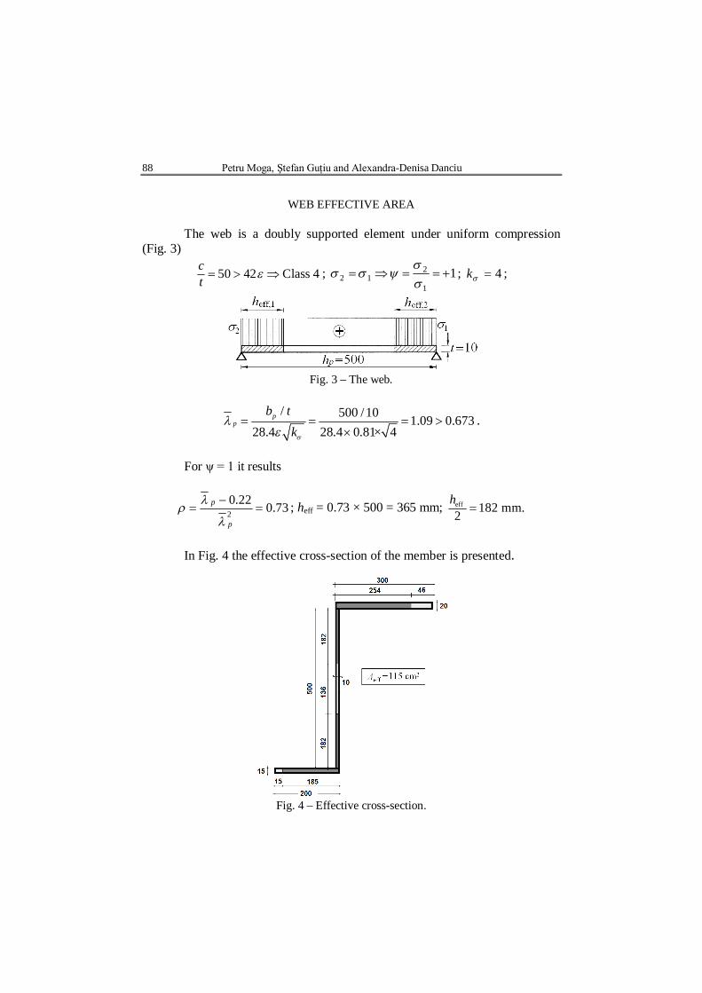
WEB EFFECTIVE AREA
The web is a doubly supported element under uniform compression
(Fig. 3)
50 42 Class 4ct ; 1
1
212
; 4k ;
Fig. 3 – The web.
/ 500 /10 1.09 0.673
28.4 28.4 0.81× 4p
pb t
k
.
For ψ = 1 it results
73.022.02
p
p
; heff = 0.73 × 500 = 365 mm; eff 182 mm.2h
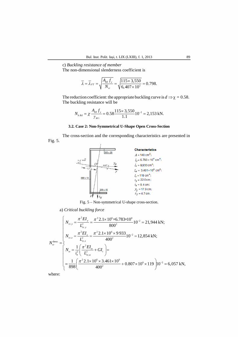
In Fig. 4 the effective cross-section of the member is presented.
Fig. 4 – Effective cross-section.
Bul. Inst. Polit. Iaşi, t. LIX (LXIII), f. 1, 2013 89
c) Buckling resistance of member The non-dimensional slenderness coefficient is
eff2
cr
115 3,550 0.798.6,407 10
yFT
A fN
The reduction coefficient: the appropriate buckling curve is d = 0.58. The buckling resistance will be
eff 2.
1
115 3,5500.58 10 2,153 kN.1.1
yb Rd
M
A fN
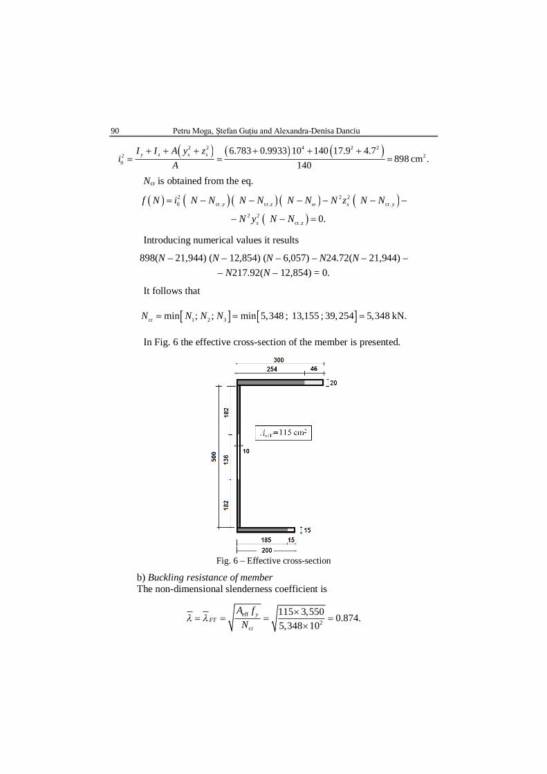
3.2. Case 2: Non-Symmetrical U-Shape Open Cross-Section
The cross-section and the corresponding characteristics are presented in
Fig. 5.
Fig. 5 – Non-symmetrical U-shape cross-section.
a) Critical buckling force
2 2 6 42
cr. 2 2cr.
2 2 62
cr. 2 2cr.theor.
cr 2
2 20 cr.
2 6 66 2
2
2.1 10 ×6.783×10 10 21,944 kN;800
2.1 10 9 93310 12,854 kN;400
1
1 2.1 10 3.461 10 0.807 10 119 10 6,0898 400
yy
y
zz
z
t
EIN
L
EINL
NEIN GI
i L
57 kN,
where:
90 Petru Moga, Ştefan Guţiu and Alexandra-Denisa Danciu
2 2 4 2 22 20
6.783 0.9933 10 140 17.9 4.7898 cm .140
y z s sI I A y zi A
Ncr is obtained from the eq.
2 2 20 cr. cr. cr.
2 2cr. 0.
y z s y
s z
f N i N N N N N N N z N N
N y N N
Introducing numerical values it results
898(N – 21,944) (N – 12,854) (N – 6,057) – N24.72(N – 21,944) –
– N217.92(N – 12,854) = 0.
It follows that
cr 1 2 3min ; ; min 5,348 ; 13,155 ; 39,254 5,348 kN.N N N N
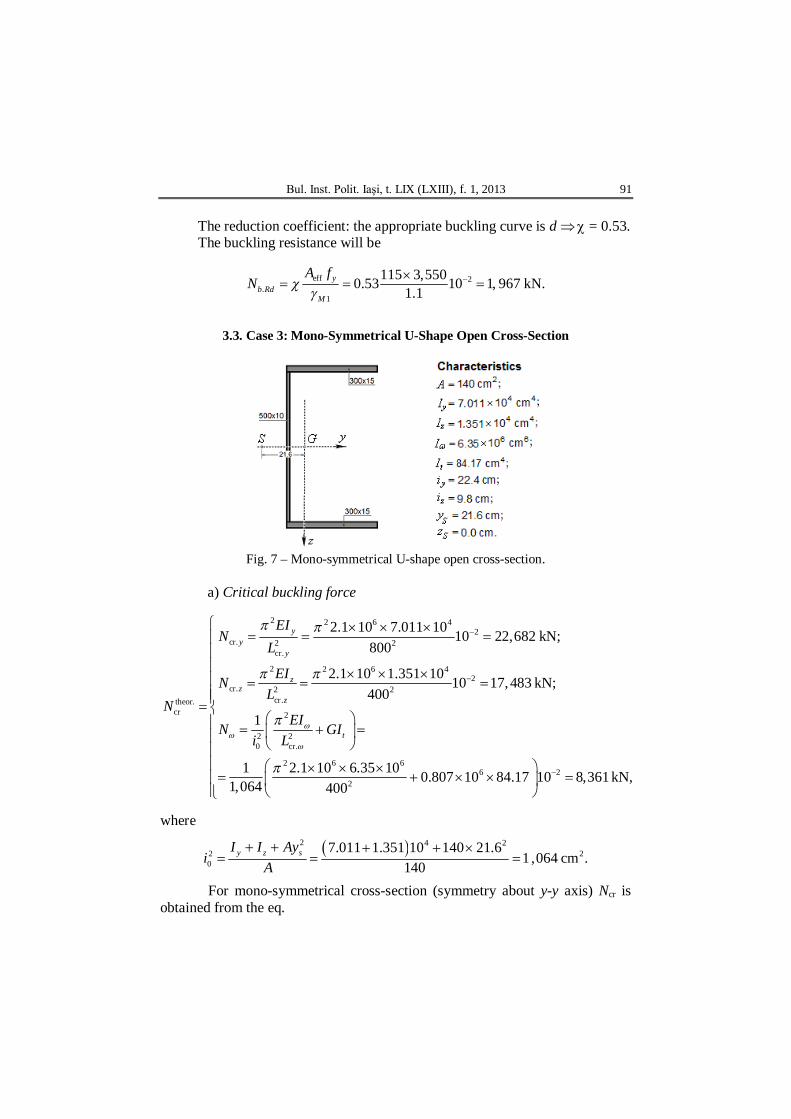
In Fig. 6 the effective cross-section of the member is presented.
Fig. 6 – Effective cross-section
b) Buckling resistance of member The non-dimensional slenderness coefficient is
eff2
cr
115 3,550 0.874.5,348 10
yFT
A fN
Bul. Inst. Polit. Iaşi, t. LIX (LXIII), f. 1, 2013 91
The reduction coefficient: the appropriate buckling curve is d = 0.53. The buckling resistance will be
eff 2.
1
115 3,5500.53 10 1, 967 kN.1.1
yb Rd
M
A fN
3.3. Case 3: Mono-Symmetrical U-Shape Open Cross-Section
Fig. 7 – Mono-symmetrical U-shape open cross-section.
a) Critical buckling force
2 2 6 4
2cr. 2 2
cr.
2 2 6 42
cr. 2 2cr.theor.
cr 2
2 20 cr.
2 6 66
2
2.1 10 7.011 10 10 22,682 kN;800
2.1 10 1.351 10 10 17,483 kN;400
1
1 2.1 10 6.35 10 0.807 10 84.171,064 400
yy
y
zz
z
t
EIN
L
EINL
NEIN GI
i L
210 8,361 kN,
where
2 4 22 20
7.011 1.351 10 140 21.61 ,064 cm .140
y z sI I Ayi A
For mono-symmetrical cross-section (symmetry about y-y axis) Ncr is obtained from the eq.
92 Petru Moga, Ştefan Guţiu and Alexandra-Denisa Danciu
20cr. cr. cr. . cr. cr. cr.
0
2
42 ( )
14.896 8.362(22,682 8,361) (22,682 8,361) 4 22,682 8 3612 8.362 14.896
6,9
y zTF y T cr y T y T
y z
I IIN N N N N N NI I I
88 kN,
where cr.TN N 8,626 kN ; 2 4 40 0 14.896 10 cm .I i A
Taking into account the obtained data it results that the relevant buckling mode is flexural–torsional buckling, where cr cr.TF 6,988 kNN N .
b) Effective cross-section The flanges are cantilevers subjected to uniform compression
19.33 14 11.34 Class 4ct ; 1
1
212
.
The buckling coefficient for the flange is 43.0k / 290 /15 1.28 0.748
28.4 28.4 0.81× 0.43p
pb t
k
.
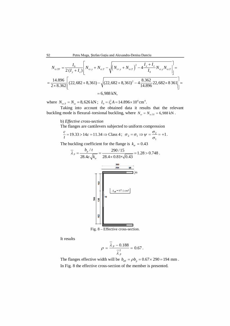
Fig. 8 – Effective cross-section.
It results
67.0188.0
2
p
p
.
The flanges effective width will be eff 0.67 290 194 mmpb b . In Fig. 8 the effective cross-section of the member is presented.
Bul. Inst. Polit. Iaşi, t. LIX (LXIII), f. 1, 2013 93
c) Buckling resistance of member The non-dimensional slenderness coefficient is
eff2
cr
97.6 3,550 0.706,988 10
yFT
A fN
.
The reduction coefficient: the appropriate buckling curve is d = 0.64. The buckling resistance will be
eff 2.
1
97.6 35500.64 10 2,016 kN1.1
yb Rd
M
A fN
.
3.4. Case 4: Mono-Symmetrical Double T-Shape Cross-Section
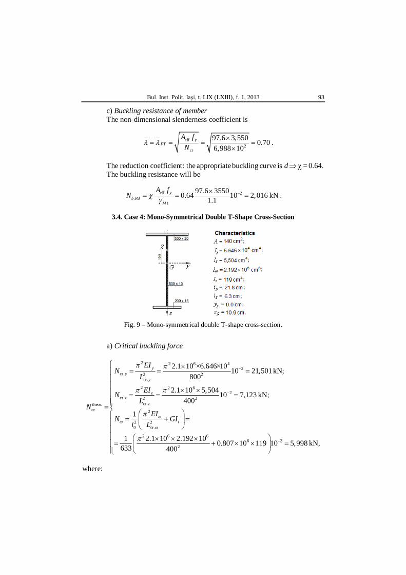
Fig. 9 – Mono-symmetrical double T-shape cross-section.
a) Critical buckling force
2 2 6 42
cr. 2 2cr.
2 2 62
cr. 2 2cr.theor.
cr 2
2 20 cr.
2 6 66 2
2
2.1 10 ×6.646×10 10 21,501 kN;800
2.1 10 5,50410 7,123 kN;400
1
1 2.1 10 2.192 10 0.807 10 119 10 5,9633 400
yy
y
zz
z
t
EIN
L
EINL
NEIN GI
i L
98 kN,
where:
94 Petru Moga, Ştefan Guţiu and Alexandra-Denisa Danciu
2 4 22 20
6.646 0.5504 10 140 10.9633 cm .140
y z sI I Azi A
For mono-symmetrical cross-section (symmetry about z-z axis), Ncr is
obtained from the eq.
20cr. cr. cr. cr. cr. cr. cr.
0
2
42 ( )
8.862 7.207,123 5,998 (7,123 5,998) 4 7,123 5,998 4,520 kN,2 7.20 8.862
y zTF z T z T z T
y z
I IIN N N N N N NI I I
where: cr.TN N 5,998 kN ; 2 4 40 0 8.862 10 cmI i A .
Taking into account the obtained data it results that the relevant buckling mode is flexural-torsional, where cr cr. 4,520 kNTFN N .
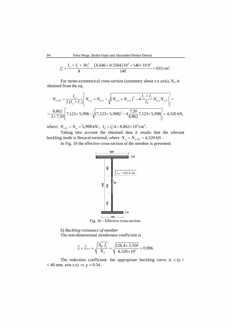
In Fig. 10 the effective cross-section of the member is presented.
Fig. 10 – Effective cross-section.
b) Buckling resistance of member The non-dimensional slenderness coefficient is
eff2
cr
126.4 3,550 0.996.4,520 10
yFT
A fN
The reduction coefficient: the appropriate buckling curve is c (tf < < 40 mm; axis z-z) 54.0 .

Bul. Inst. Polit. Iaşi, t. LIX (LXIII), f. 1, 2013 95
The buckling resistance will be
eff 2.
1
126.4 3,5500.54 10 2,203 kN1.1
yb Rd
M
A fN
.
3.5. Case 5: Double-Symmetrical Double T Shape Cross-Section
Fig. 11 – Double-symmerical double T shape cross-section.
a) Critical buckling force
2 2 6 42
cr. 2 2cr.
2 2 62
cr. 2 2cr.theor.
cr 2
2 20 cr.
2 6 66 2
2
2.1 10 ×7.011 10 10 22,682 kN;800
2.1 10 ×6,75410 8,740 kN;400
1
1 2.1 10 4.473 10 0.807 10 84.17 10 1549 400
yy
y
zz
z
t
EIN
L
EINL
NEIN GI
i L
1,780 kN,
where:
42 20
7.011 0.6754 10549 cm .140
y zI Ii A
Taking into account the obtained data it results that the relevant buckling mode is flexural buckling about z-z axis, where cr cr. 8,740 kN.zN N
b) Effective cross-section Flanges: Class 3. Web: Class 4.
96 Petru Moga, Ştefan Guţiu and Alexandra-Denisa Danciu
In Fig. 12 the effective cross-section of the member is presented.
Fig. 12 – Effective cross-section
c) Buckling resistance of member The non-dimensional slenderness coefficient is
eff2
cr
126.4 3,550 0.716.8,740 10
yFT
A fN
The reduction coefficient: the appropriate buckling curve is c (tf < 40 mm;
axis z-z) 0.71. The buckling resistance will be
eff 2.
1
126.4 3,5500.71 10 2,896 kN.1.1
yb Rd
M
A fN
3.6. Case 6: Cross Shape Mono-Symmetrical Cross-Section
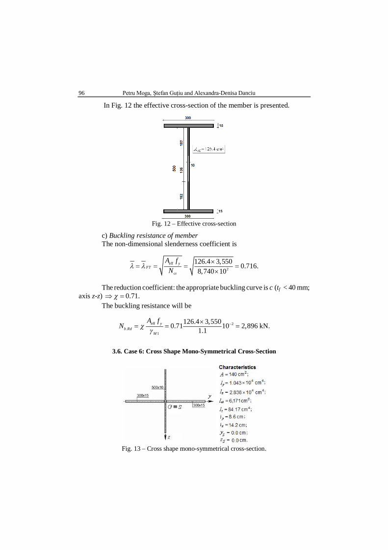
Fig. 13 – Cross shape mono-symmetrical cross-section.
Bul. Inst. Polit. Iaşi, t. LIX (LXIII), f. 1, 2013 97
a) Critical buckling force
2 2 6 42
cr. 2 2cr.
2 2 6 42
cr. 2 2cr.theor.
cr 2
2 20 cr.
2 66 2
2
2.1 10 1.043 10 10 3,374 kN;800
2.1 10 2.838 10 10 3,673 kN;400
1
1 2.1 10 6,171 0.807 10 84.17 10 2,277 400
yy
y
zz
z
t
EIN
L
EINL
NEIN GI
i L
481 kN,
where
42 20
1.043 2.838 10277 cm .140
y zI Ii A
Taking into account the obtained data it results that the relevant
buckling mode is torsional: cr cr. 2,481 kN.TN N N .
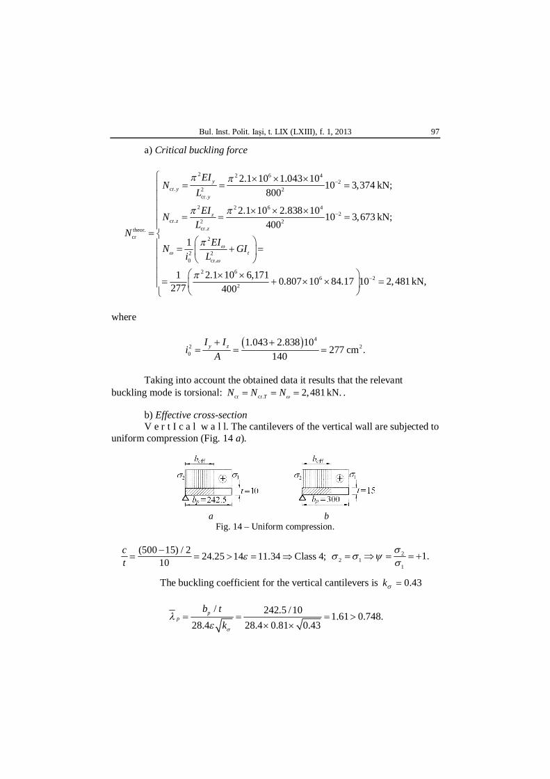
b) Effective cross-section V e r t I c a l w a l l. The cantilevers of the vertical wall are subjected to
uniform compression (Fig. 14 a).
a b
Fig. 14 – Uniform compression.
(500 15) / 2 24.25 14 11.34 Class 4;10ct
2
2 11
1.
The buckling coefficient for the vertical cantilevers is 43.0k
/ 242.5 /10 1.61 0.748.
28.4 28.4 0.81 0.43p
pb t
k
98 Petru Moga, Ştefan Guţiu and Alexandra-Denisa Danciu
It results
55.0188.02
p
p
.
Effective width
eff 0.55 242.5 133 mm.pb b .
H o r i z o n t a l w a l l. The cantilevers of the horizontal wall are subjected to uniform compression (Fig. 14 b)
300 20 14 11.34 Class 4;15
ct 2
2 11
1.
The buckling coefficient for the horizontal cantilevers is k = 0.43
/ 20 1.33 0.748.28.4 28.4 0.81 0.43
pp
b tk
It results
65.0188.02
p
p
.
Effective width
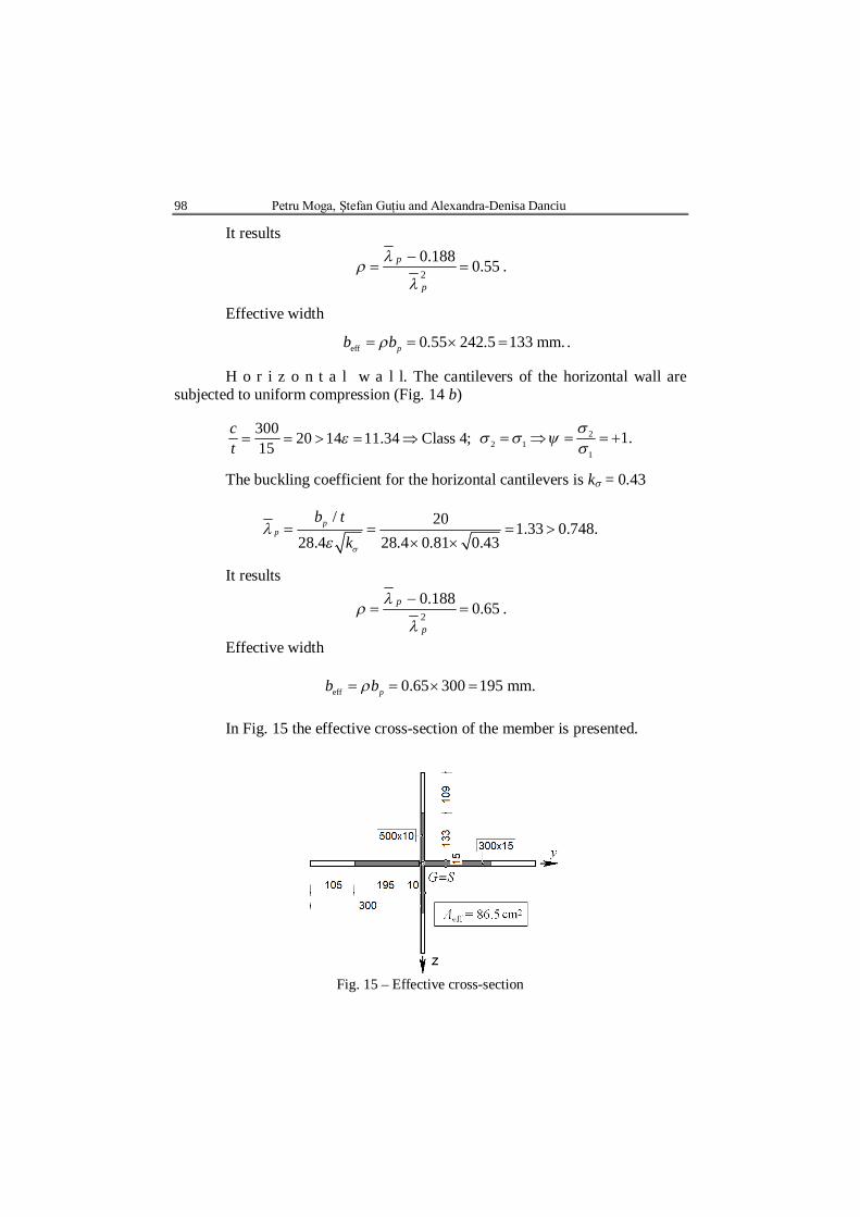
eff 0.65 300 195 mm.pb b In Fig. 15 the effective cross-section of the member is presented.
Fig. 15 – Effective cross-section
Bul. Inst. Polit. Iaşi, t. LIX (LXIII), f. 1, 2013 99
c) Buckling resistance of member The non-dimensional slenderness coefficient is
eff2
cr
86.5 3,550 1.11.2,481 10
yFT
A fN
The reduction coefficient: the appropriate buckling curve is d = 0.41. The buckling resistance will be
eff 2.
1
86.5 3,5500.41 10 1,145 kN.1.1
yb Rd
M
A fN
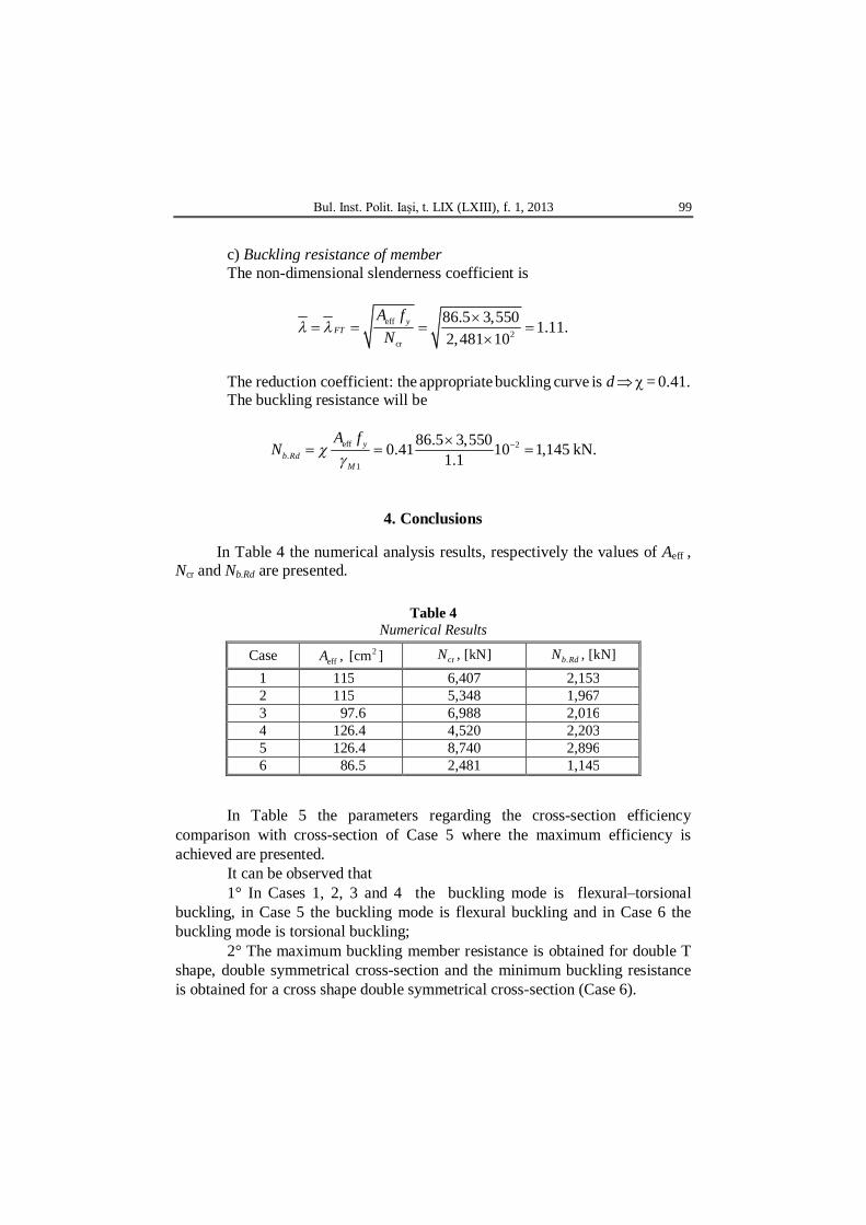
4. Conclusions
In Table 4 the numerical analysis results, respectively the values of Aeff , Ncr and Nb.Rd are presented.
Table 4
Numerical Results
Case 2eff , [cm ]A cr , [kN]N . , [kN]b RdN
1 115 6,407 2,153 2 115 5,348 1,967 3 97.6 6,988 2,016 4 126.4 4,520 2,203 5 126.4 8,740 2,896 6 86.5 2,481 1,145
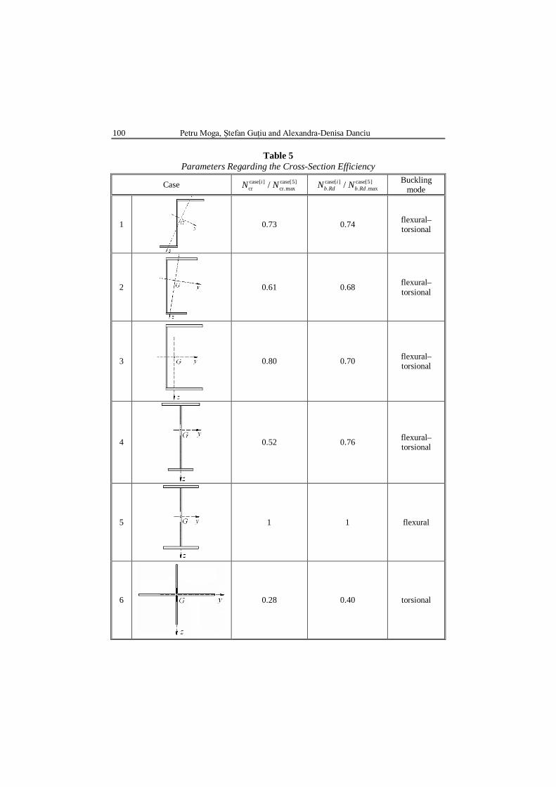
In Table 5 the parameters regarding the cross-section efficiency comparison with cross-section of Case 5 where the maximum efficiency is achieved are presented.
It can be observed that 1° In Cases 1, 2, 3 and 4 the buckling mode is flexural–torsional
buckling, in Case 5 the buckling mode is flexural buckling and in Case 6 the buckling mode is torsional buckling;
2° The maximum buckling member resistance is obtained for double T shape, double symmetrical cross-section and the minimum buckling resistance is obtained for a cross shape double symmetrical cross-section (Case 6).
100 Petru Moga, Ştefan Guţiu and Alexandra-Denisa Danciu
Table 5 Parameters Regarding the Cross-Section Efficiency
Case case[ ] case[5]cr cr.max/iN N case[ ] case[5]
. . .max/ib Rd b RdN N Buckling
mode
1
0.73 0.74 flexural–torsional
2
0.61 0.68 flexural–torsional
3
0.80 0.70 flexural–torsional
4
0.52 0.76 flexural–torsional
5
1 1 flexural
6
0.28 0.40 torsional

Bul. Inst. Polit. Iaşi, t. LIX (LXIII), f. 1, 2013 101
REFERENCES
Moga P., Guţiu Şt., Moga C., Proiectarea elementelor din oţel. Aplicare euronorme.
Edit. Univ. Tehn. Cluj-Napoca, 2011. *
* * Eurocod 3: Proiectarea structurilor de oţel. Partea 1-1: Reguli generale şi reguli
pentru clădiri. SR EN 1993-1-1/2006. *
* * Eurocod 3: Proiectarea structurilor de oţel. Partea 1-5: Elemente din plăci plane
solicitate în planul lor. SR EN 1993-1-5/2006. *
* * European Steel Design Education Programme. The ESDEP Society ESDEP (1994).
The Steel Constr. Inst., Bekshire, UK. INFLUENŢA FORMEI SECŢIUNII TRANSVERSALE ASUPRA REZISTENŢEI LA
FLAMBAJ A BARELOR COMPRIMATE
(Rezumat) Se prezintă pe scurt metodologia de proiectare a barelor de secţiune
transversală deschisă, supuse la compresiune uniformă, în conformitate cu normativul EN 1993-1-1/2006. Eurocod 3: Proiectarea structurilor de oţel
Baza de calcul teoretic este însoţită de o analiză comparativă numerică, pentru şase tipuri de secţiuni transversale deschise, în urma căreia au putut fi formulate concluzii şi observaţii referitoare la influenţa formei secţiunii transversale asupra rezistenţei la flambaj.
