influence of the linear tip relief modification in spur
TRANSCRIPT

INFLUENCE OF THE LINEAR TIP RELIEF MODIFICATION IN SPUR GEARS AND
EXPERIMENTAL EVIDENCE
Authors:
Marco Beghini
Fabio Presicce
Ciro Santus
Gian Mario Bragallini
Collaboration between
DIMNP, Università di Pisa
AVIO S.p.A. Propulsione Aerospaziale, Torino

Application of interest
2
Gear Box for Aerospace vehicles
• high performance
• low weightSpur Gears

Tip Relief Modification
What is Tip Relief Modification ?
Material removal along the involute profile at the tip of the tooth
Bidimensionalsketch for a modified Spur Gears Tooth
What is the use of Tip Relief Modification ?
• Better meshing engagement of tooth pairs
• Transmission Error trace modified (PPTE reduced) 3
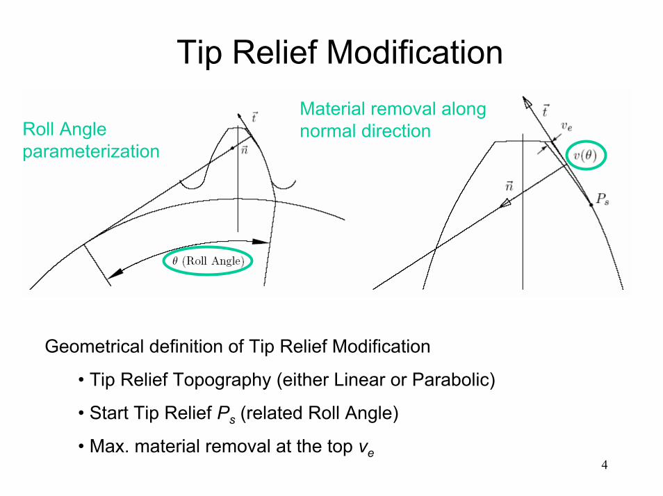
Tip Relief ModificationMaterial removal along normal directionRoll Angle
parameterization
Geometrical definition of Tip Relief Modification
• Tip Relief Topography (either Linear or Parabolic)
• Start Tip Relief Ps (related Roll Angle)
• Max. material removal at the top ve4
Linear Tip Relief Modification
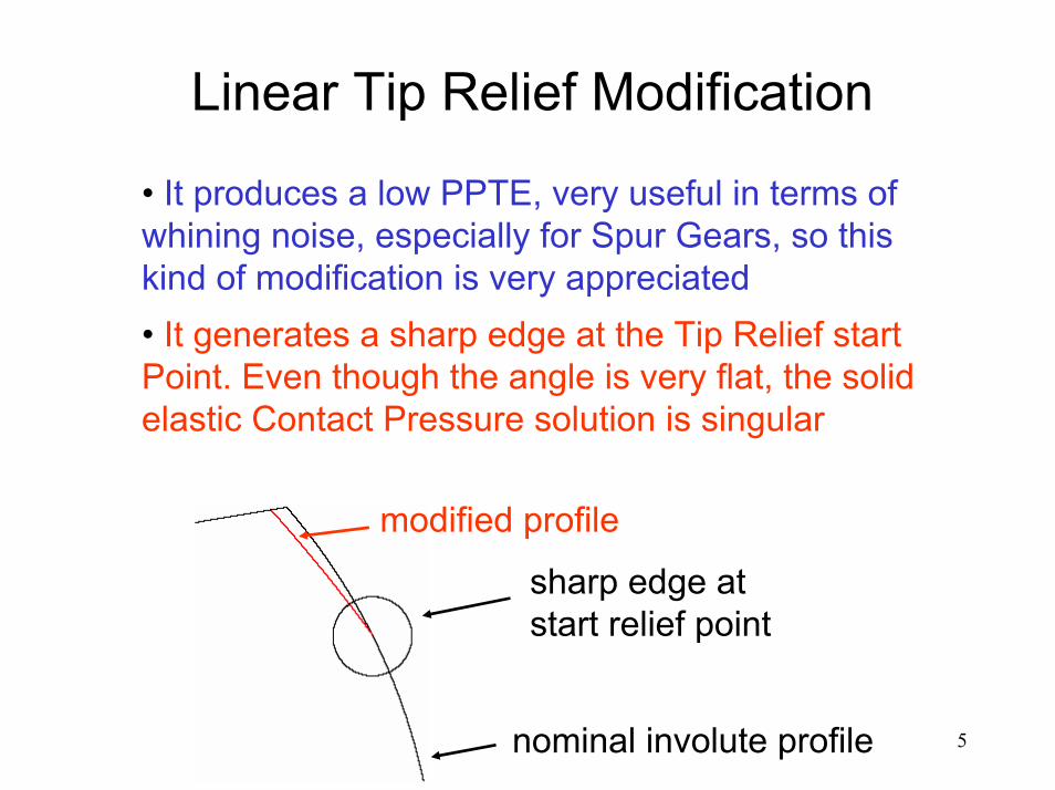
• It produces a low PPTE, very useful in terms of whining noise, especially for Spur Gears, so this kind of modification is very appreciated• It generates a sharp edge at the Tip Relief start Point. Even though the angle is very flat, the solid elastic Contact Pressure solution is singular
sharp edge at start relief point
nominal involute profile
modified profile
5

Linear Tip Relief Modification
• Nominal Contact Pressure solution
If the contact zone encompasses one or both the start relief points, Contact Pressure rises to infinity
6
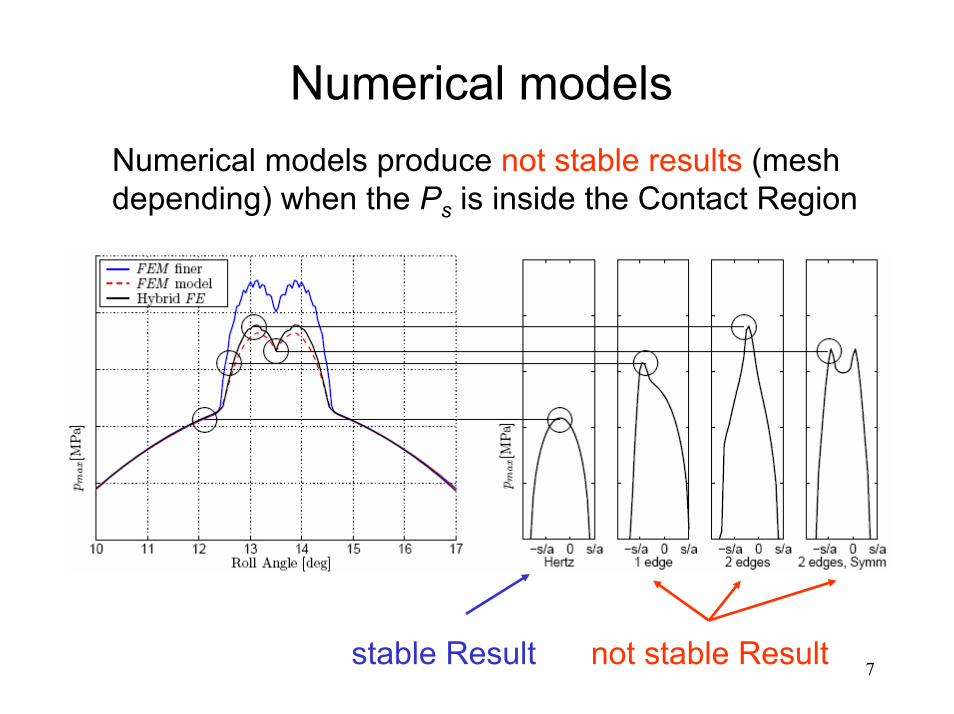
Numerical modelsNumerical models produce not stable results (mesh depending) when the Ps is inside the Contact Region
stable Result not stable Result 7

Why not to accept sharp edge and singular contact pressure
• Every technological process can not produce a perfectly sharp edge
• The angle at the tip relief start point is so flat that the surface roughness has to be considered for defining the corner region
• After a short run in the material necessarily yields or wears, and sharp edges should be blunted
8

Micro pitting prediction model needed
• If C2 (even C1) continuity condition is satisfied the Hertz Contact Pressure is accepted to be the nominal stress for Micro-Pitting material resistance prediction
Nominal Hertz max. Pressure
• If C0 continuity condition is satisfied only, a nominal Contact Pressure stress value is not available
Nominal max. Pressure needed
9
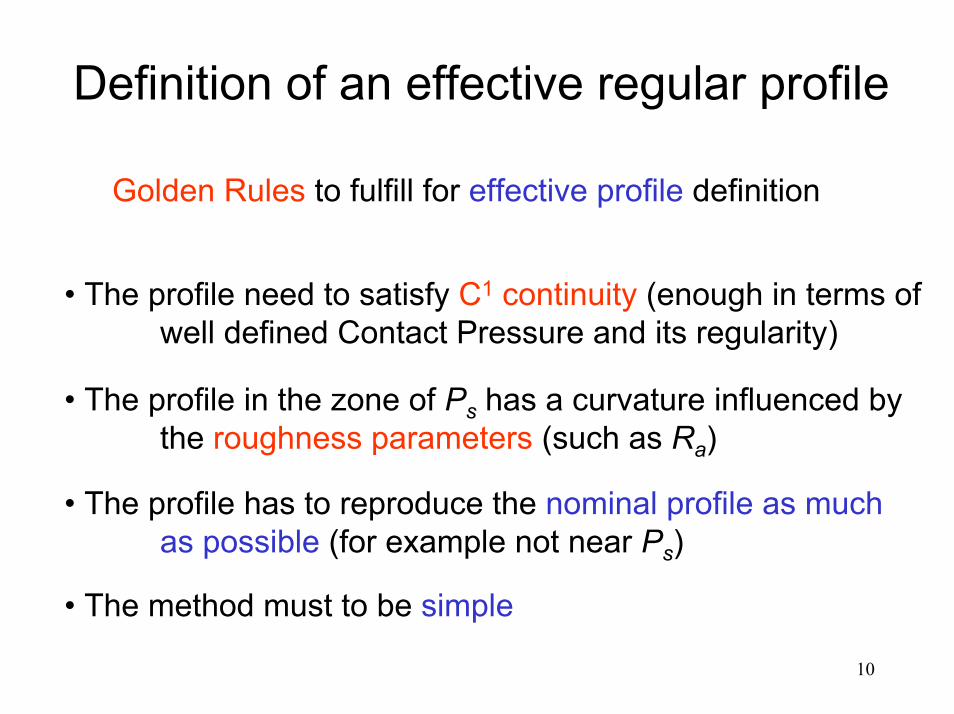
Definition of an effective regular profile
Golden Rules to fulfill for effective profile definition
• The profile need to satisfy C1 continuity (enough in terms of well defined Contact Pressure and its regularity)
• The profile in the zone of Ps has a curvature influenced bythe roughness parameters (such as Ra)
• The profile has to reproduce the nominal profile as much as possible (for example not near Ps)
• The method must to be simple
10

Data for the definition of an effective regular profile
Experimental data available: 800 profiles points inside the design tolerance band, on which define the effective profile
11
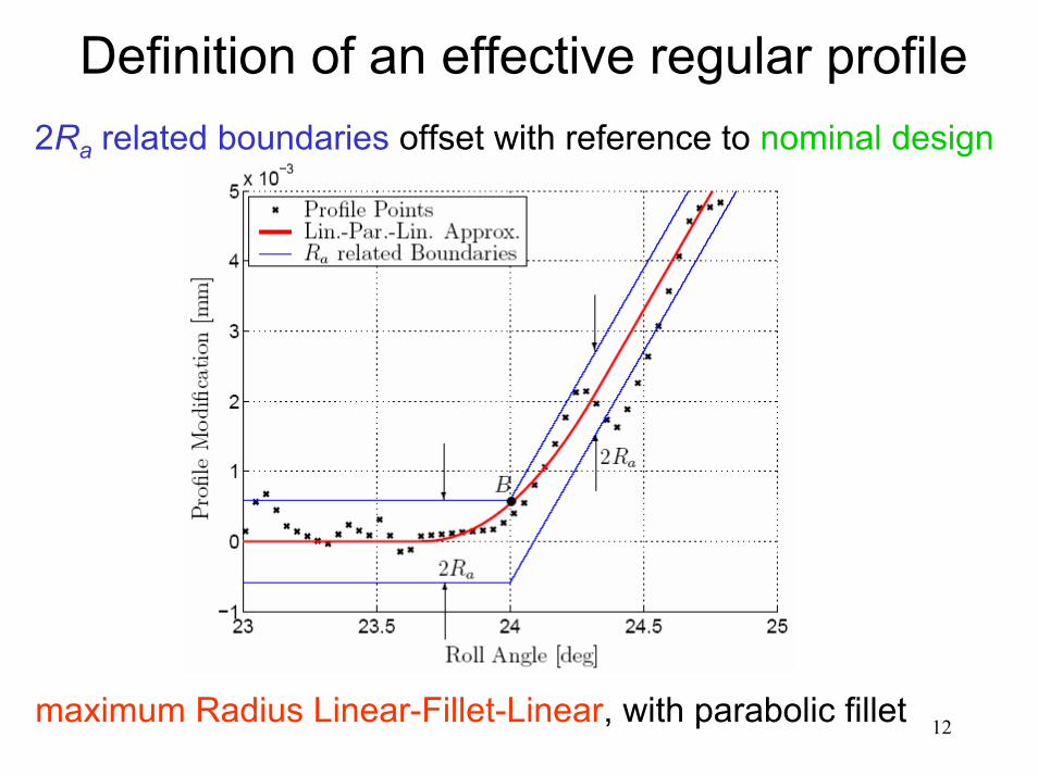
Definition of an effective regular profile2Ra related boundaries offset with reference to nominal design
maximum Radius Linear-Fillet-Linear, with parabolic fillet 12

Definition of an effective regular profile
Strong curvature step, but C1 condition fulfilled
13

Definition of an effective regular profile
Quite narrow statistical distribution of fillet Radii
14

Contact Pressure Results
• Numerical stable results
• Different combinations for statistical sake, then statistical results variation
• Very high Contact Pressure found 15

Contact Pressure Results
Profile and related points, plus Acquisition limits
Nominal Modification, plusacquisition points
16
Contact Pressure evolution on the profile
Contact Pressure rise due to “sharp edges” in contact

Experimental Evidence
Experimental equipment for Profile and Roughness detection
Equipment scheme for “horizontal tooth flank”displacement
17

Experimental Evidence
18
Micro-Pits found
Micro-Pitting lines
Evidence of opposite Rolling-Sliding combinations, from Pits’ borders
Conclusion
• A simple method to perform a regression to a regular profile, in the case of singular nominally profile, was shown and experimentally validated.
• The only micro-geometry parameter leading the regression is the roughness Ra, around the Start Relief Point.
• Numerical simulations were performed and micro-pitting evidence provided for the high contact pressure found.
• The coincidence found is good.
19