influence of tool thread on the mechanical properties of dissimilar al-alloy friction stir spot...
TRANSCRIPT

Influence of tool thread on the mechanical properties of dissimilar Al-alloy friction stir spot welds
Ikuta Akihikoa, Yin Yuhuanb and North Thomas Hc
aSchool of Engineering, Kinki University, Hiroshima, Japan; bSchool of Material Science and Engineering, Tianjin University, Tianjin,P.R. China; cDepartment of Materials Science and Engineering, University of Toronto, Toronto, Canada
(Received 17 May 2010; final version received 23 August 2010)
The influence of threaded and wear simulated (half-thread) tools on the mechanical properties of dissimilar Al-alloy frictionstir spot welds is investigated. The failure load properties of dissimilar A5754/A6111 lap joints produced using wearsimulated (half-thread) tools were much poorer in joints made using tool rotational speeds of 1000 and 1500 rpm. Similarfailure load properties were produced using these tools, when the tool rotational speed was increased to 2250 rpm. In jointsmade using a tool rotational speed of 3000 rpm, the failure load properties of joints made using the half-thread tool werehigher than those of joints made using the threaded tool. Similar failure load properties were found in A5052/A6061 lap andbutt joints made using threaded, half-threaded and no thread tools and a tool rotational speed of 1000 rpm. Also, the failureload properties of lap joints made using the different tools corresponded with their bonded widths and Y values. The area ofthe stir zone on the bonded cross section corresponded with the actual bonded region on the fracture surface ofA5052/A6061 butt joints. However, the weld profiles were different from those in A5052/A6061 lap joints. It is, therefore,suggested that the failure load properties of lap joints are similar when the bonded widths and Y values are similar. Inaddition, the thread on the cylindrical probe has negligible influence on the mechanical properties of lap joints. The majorrole played by the thread involves stirring in the vertical direction. Stirring in the horizontal direction is unchanged in jointsmade using the different tools.
Keywords: friction stir spot welding; aluminium alloy; mechanical properties; thread; tool wear
1. Introduction
With the increasing use of aluminium alloys in recent years,
friction stir spot welding (FSSW), a form of friction stir
welding (FSW) has attracted interest in the automotive
industry as a substitute for the previously used resistance
spot welding [1–5]. Studies aimed at applying the technique
to high-tensile strength and other steels is also continuing.
On the other hand, there are currently few reports on the
tools that are essential for joining using both FSW and
FSSW. Possibly, information on tool shapes and tool wear
during welding is of a nature that makes it difficult to make
public as part of individual production technologies but it
will be necessary to obtain basic findings on friction
welding tools for this technique to be used more widely.
In FSW, the probe, regarded as the usual tool, does not
necessarily require a thread and there have been reports
[6,7] that there is almost no effect on the joint properties
even in a tool where the thread wears and is then auto-
optimized, and also a report [8] that a thread is not
necessarily required for materials which readily experi-
ence plastic flow and even with materials which do not
readily exhibit plastic flow, joining may be possible
depending on the welding conditions. In FSSW, however,
it may be impossible or difficult to form a stir zone unless
the probe is threaded [9,10]. These findings indicate that
for FSSW probe thread wear has a major effect on whether
joining can continue without loss of quality. However,
even for FSSW a range of tool shapes have recently been
proposed for the welding of various metals [11–14]. In
future considerations of tool shape, how to address the
problems of whether to use a thread and how it will wear
will also bring questions of increasing importance for
FSW. Against this background, how to carry out welding
of high-tensile strength steel and dissimilar metal welding
between different aluminium alloys and steel and
aluminium alloy, techniques which are not yet established,
will be an important for FSSW in its role as a welding
technique that can replace resistance spot welding in the
automotive industry. In such cases, the questions of what
tool shape to use for badly weldable metals and how to
handle tool wear to maintain joint quality are particularly
important for future applications of FSSW and a policy
will be necessary to answer these.
In this study, different aluminium alloys were lap
welded by FSSW, using a tool with simulated worn probe
thread, with the aim of discovering the effect of the thread
of a standard probe on the mechanical properties of FSSW
joints. After welding, tensile shear tests were carried out
on the joint and the microstructure of the weld was
examined and an examination was made of the effect of
probe thread on the change factors for weldability.
2. Test metals and experimental methods
2.1 Test metals
Since a tool with simulated probe thread wear was used,
weld metals in which wear progresses markedly during the
experiment were not desirable for this study. The
aluminium alloys used were A5754-H12 (hereafter:
A5754) and A6111-T4 (hereafter: A6111) since welding
of these is currently being actively carried out [15–17] and
the state of the stir in the upper and lower sheets is easily
observable. Other 5000-grade and 6000-grade aluminium
alloys used were A5052-H34 (hereafter: A5052) and
A6061-T651 (hereafter: A6061). The chemical compo-
sitions of these are shown in Table 1. The dimensions of
the alloys were 100mm long and 25mm wide, with the
q 2013 Taylor & Francis
Welding International, 2013
http://dx.doi.org/10.1080/09507116.2012.753246
Selected from Quarterly Journal of the Japan Welding Society 28(3) 346–354

thickness being 1.6mm for A5754, 1.5mm for A6111,
1.5mm or 3mm for A5052 and 3mm for A6061.
2.2 Friction stir spot welding
The welding conditions for FSSW were a tool rotational
speed varied between 1000, 1500, 2250 and 3000 rpm, a
plunging speed of 2.5mm/s, a dwell time (the time the
position after plunging is maintained) of 1 s and a constant
shoulder plunging depth of 0.5mm. The welding method
was that the upper plate was 5000-grade (A5754 or
A5052) and the lower plate was 6000-grade (A6111 or
A6061), the overlap was 25mm and welding was carried
out at the centre of this.
2.3 FSSW tools
The tools used for welding were H13 tool steel (JIS
SKD61 equivalent), which was machined and then heat-
treated so that the hardness was HRc 46–48. As shown in
Figure 1, the shape of the probes was a standard cylindrical
shape, with a shoulder diameter of 10mm and a probe
length of 2.2mm. In order to examine the effect of wear,
welding was carried out using a tool with a cylindrical
probe that had been M4 threaded (hereafter: threaded tool)
and a tool in which the M4 threaded part has been further
machined to reduce the thread height by half and simulate
wear (hereafter: half-thread tool). In some cases, a tool
with an unthreaded cylindrical probe (hereafter:
unthreaded tool) was used.
2.4 Assessment of the weld
After FSSW, tensile shear fracture tests were carried out
on the joint obtained. The test method was that the as-
welded joint was stretched and the load at which shear
fracture occurred was assessed. The elongation speed was
1mm/min. The joint was cut in the cross-sectional
direction and mirror polished before being etched with
Keller’s reagent (hydrofluoric acid 2ml, hydrochloric acid
3ml, nitric acid 5ml and distilled water 190ml) and the
microstructure examined using an optical microscope.
At this time, in order to quantify the state of the joint, as
shown in Figure 2, the parameters of the distance from the
probe surface to the tip of the hook (an oxide layer at the
interface between the upper plate metal and lower plate
metal) [17,18] (hereafter: Y value) [19], the angle formed
between the hook and the initial interface between the
upper and lower plates (hereafter: curvature) and the
distance between the probe surface to the weld start point,
that is, the total of the stir zone width [20] and deformed
metal width (hereafter: bonded width) were measured. The
Y value and bonded width were measured using an optical
microscope with a magnification of 500-fold. For the Y
value, the position at which the hook fragmented was
taken as the hook tip. If, however, the hook had large
irregularities, the position on the hook baseline at which
the hook broke up was taken as the hook tip as shown in
Figure 2.
Table 1. Chemical compositions of base materials (wt%).
Materials Cu Mg Mn Si Fe Cr Zn Ti Al
A5754-H12 ,0.01 3.01 0.47 ,0.10 – – – – Bal.A6111-T4 0.75 0.75 0.20 0.69 – – – – Bal.A5052-H34 0.01 2.38 0.04 0.08 0.19 0.20 0.01 - Bal.A6061-T651 0.26 1.0 0.05 0.60 0.25 0.16 0.01 0.02 Bal.
M4
2.2
Threaded Half-thread No thread
φ4 φ4φ10
φ3.6
Figure 1. Different tool designs.
Top of hook
Hook
A
Shou
lder
pene
trat
ion
dept
h
Y
v
Upper sheet
Lower sheet
Sheetintersection
t
Rotating tool
Displaced material width
Bonded width
Stir zonewidth
Detail A
Curva
ture
Figure 2. Schematic illustration showing the measurement ofthe stir zone and bonded widths, Y values, shoulder penetrationdepths and the curvatures of the hook regions.
I. Akihiko et al.2
3. Experimental results and discussion
3.1 Results of tensile shear fracture tests
Figure 3 shows the results of tensile shear fracture tests of
lap joints combining A5754 and A6111, when each of the
tools was used and the tool rotational speed was varied.
First, for the threaded tool, the changes of the tensile shear
strength when the tool rotational speed was varied showed
a low value at 1000 rpm and the highest value, of around
1.8 kN, at 1500 rpm but then fell as the tool rotational
speed increased, with the lowest value at 3000 rpm. For the
half-thread tool tensile shear strength increased linearly
with rotational speed of tool up to 2250 rpm, thereafter
becoming constant, showing the maximum value of
around 1.5 kN at 3000 rpm. The difference in tensile shear
strength between the threaded tool and half-thread tool
was greatest (approximately 1 kN at a slow rotational
speed, whereas the tensile shear strengths were almost the
same (1.2–1.5 kN) at the higher speed. It can thus be
inferred that the tendencies of the threaded tool and half-
thread tool differed and the factors affecting the
mechanical properties of the joints were also different.
3.2 Results of observation of joint structure
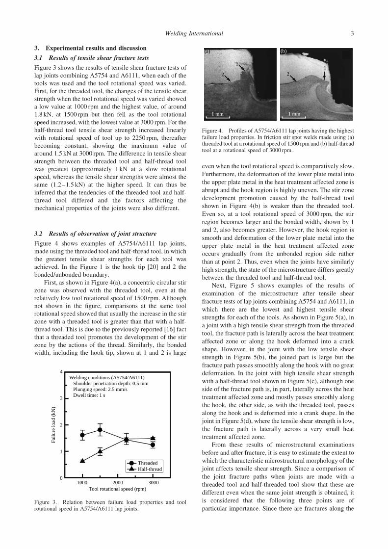
Figure 4 shows examples of A5754/A6111 lap joints,
made using the threaded tool and half-thread tool, in which
the greatest tensile shear strengths for each tool was
achieved. In the Figure 1 is the hook tip [20] and 2 the
bonded/unbonded boundary.
First, as shown in Figure 4(a), a concentric circular stir
zone was observed with the threaded tool, even at the
relatively low tool rotational speed of 1500 rpm. Although
not shown in the figure, comparisons at the same tool
rotational speed showed that usually the increase in the stir
zone with a threaded tool is greater than that with a half-
thread tool. This is due to the previously reported [16] fact
that a threaded tool promotes the development of the stir
zone by the actions of the thread. Similarly, the bonded
width, including the hook tip, shown at 1 and 2 is large
even when the tool rotational speed is comparatively slow.
Furthermore, the deformation of the lower plate metal into
the upper plate metal in the heat treatment affected zone is
abrupt and the hook region is highly uneven. The stir zone
development promotion caused by the half-thread tool
shown in Figure 4(b) is weaker than the threaded tool.
Even so, at a tool rotational speed of 3000 rpm, the stir
region becomes larger and the bonded width, shown by 1
and 2, also becomes greater. However, the hook region is
smooth and deformation of the lower plate metal into the
upper plate metal in the heat treatment affected zone
occurs gradually from the unbonded region side rather
than at point 2. Thus, even when the joints have similarly
high strength, the state of the microstructure differs greatly
between the threaded tool and half-thread tool.
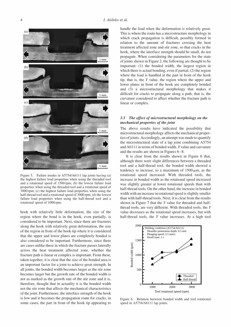
Next, Figure 5 shows examples of the results of
examination of the microstructure after tensile shear
fracture tests of lap joints combining A5754 and A6111, in
which there are the lowest and highest tensile shear
strengths for each of the tools. As shown in Figure 5(a), in
a joint with a high tensile shear strength from the threaded
tool, the fracture path is laterally across the heat treatment
affected zone or along the hook deformed into a crank
shape. However, in the joint with the low tensile shear
strength in Figure 5(b), the joined part is large but the
fracture path passes smoothly along the hook with no great
deformation. In the joint with high tensile shear strength
with a half-thread tool shown in Figure 5(c), although one
side of the fracture path is, in part, laterally across the heat
treatment affected zone and mostly passes smoothly along
the hook, the other side, as with the threaded tool, passes
along the hook and is deformed into a crank shape. In the
joint in Figure 5(d), where the tensile shear strength is low,
the fracture path is laterally across a very small heat
treatment affected zone.
From these results of microstructural examinations
before and after fracture, it is easy to estimate the extent to
which the characteristic microstructural morphology of the
joint affects tensile shear strength. Since a comparison of
the joint fracture paths when joints are made with a
threaded tool and half-threaded tool show that these are
different even when the same joint strength is obtained, it
is considered that the following three points are of
particular importance. Since there are fractures along the
2
1 mm
1
(a)
2
1 mm
1
(b)
Figure 4. Profiles of A5754/A6111 lap joints having the highestfailure load properties. In friction stir spot welds made using (a)threaded tool at a rotational speed of 1500 rpm and (b) half-threadtool at a rotational speed of 3000 rpm.
Welding conditions (A5754/A6111)Shoulder penetration depth: 0.5 mmPlunging speed: 2.5 mm/sDwell time: 1 s
4
3
2
1
0
Tool rotational speed (rpm)1000 2000 3000
ThreadedHalf-thread
Failu
re lo
ad (
kN)
Figure 3. Relation between failure load properties and toolrotational speed in A5754/A6111 lap joints.
Welding International 3
hook with relatively little deformation, the size of the
region where the bond is in the hook, even partially, is
considered to be important. Next, since there are fractures
along the hook with relatively great deformation, the size
of the region in front of the hook tip where it is considered
that the upper and lower plates are completely bonded is
also considered to be important. Furthermore, since there
are cases unlike these in which the fracture passes laterally
across the heat treatment affected zone, whether the
fracture path is linear or complex is important. From these,
taken together, it is clear that the size of the bonded area is
an important factor for a joint to achieve great strength. In
all joints, the bonded width becomes larger as the stir zone
becomes larger but the growth rate of the bonded width is
not as marked as the growth rate of the stir zone and it is,
therefore, thought that in actuality it is the bonded width
not the stir zone that affects the mechanical characteristics
of the joint. Furthermore, the interface strength of the hook
is low and it becomes the propagation route for cracks, in
some cases, the part in front of the hook tip appearing to
handle the load when the deformation is relatively great.
This is where the route has a microstructure morphology in
which crack propagation is difficult, possibly formed in
relation to the amount of fractures crossing the heat
treatment affected zone and stir zone, so that cracks in the
hook, where the interface strength should be small, do not
propagate. When considering the parameters for the state
of joints shown in Figure 2, the following are thought to be
important: (1) the bonded width, the largest region in
which there is actual bonding, even if partial, (2) the region
where the load is handled at the part in front of the hook
tip, that is, the Y value, the region where the upper and
lower plates in front of the hook are completely bonded
and (3) a microstructural morphology that makes it
difficult for cracks to propagate along a path, that is, the
curvature considered to affect whether the fracture path is
linear or complex.
3.3 The effect of microstructural morphology on themechanical properties of the joint
The above results have indicated the possibility that
microstructural morphology affects the mechanical proper-
ties of joints. Accordingly, an attempt wasmade to quantify
the microstructural state of a lap joint combining A5754
and A6111 in terms of bonded width, Y value and curvature
and the results are shown in Figures 6–8.
It is clear from the results shown in Figure 6 that,
although there were slight differences between a threaded
tool and a half-thread tool, the bonded width showed a
tendency to increase, to a maximum of 1500mm, as the
rotational speed increased. With threaded tools, the
increase in bonded width as the rotational speed increased
was slightly greater at lower rotational speeds than with
half-thread tools. On the other hand, the increase in bonded
widthwith an increase in rotational speed is slightly smaller
than with half-thread tools. Next, it is clear from the results
shown in Figure 7 that the Y value for threaded and half-
thread tools, are very different. With threaded tools, the Y
value decreases as the rotational speed increases, but with
half-thread tools, the Y value increases. At a high tool
(a)
(b)
(c)
(d)
1 mm
1 mm
1 mm
1 mm
Figure 5. Failure modes in A5754/A6111 lap joints having (a)the highest failure load properties when using the threaded tooland a rotational speed of 1500 rpm; (b) the lowest failure loadproperties when using the threaded tool and a rotational speed of3000 rpm; (c) the highest failure load properties when using thehalf-thread tool and a rotational speed of 3000 rpm; (d) the lowestfailure load properties when using the half-thread tool and arotational speed of 1000 rpm.
2000Welding conditions (A5754/A6111)
Shoulder penetration depth: 0.5 mmPlunging speed: 2.5 mm/sDwell time: 1 s
1500
Bon
ded
wid
th (
µm)
1000
500
01000 2000 3000
Tool rotational speed (rpm)
ThreadedHalf-thread
Figure 6. Relation between bonded width and tool rotationalspeed in A5754/A6111 lap joints.
I. Akihiko et al.4

rotational speed, the Y value was 200–300mm for both
threaded and half-thread tools but at a low rotational speed
there was a marked difference in Y values: approximately
535mm for a threaded tool and approximately 175mm for a
half-thread tool. It is also clear from the results shown in
Figure 8 that for both threaded and half-thread tools a
curvature of 1258 at a low rotational speed increases to 1558
at a high rotational speed.
Figure 9 shows curvature of typical traced upper and
lower plate interfaces of joints made using a threaded tool
and a half-thread tool. If these are taken together with
Figure 6–8, and the differences in tensile shear strength of
the joints made by the different tools are taken into
consideration, the fact that a threaded tool shows a high
tensile shear strength at a low rotational speed, as shown in
Figure 9(a), is evidently due to the Y value being largewhile
the bondedwidth is comparatively sufficient.As also shown
in the low rotational speed case of Figure 9(b), the half-
thread tool achieves a comparatively sufficient bonded
width at low rotational speed but the tensile shear strength is
reduced, evidently due to the Y value being low. It is also
thought that, when the rotational speed increases, as shown
in the high rotational speed case in Figure 9(b), with a half-
thread tool, both the bondedwidth and Y value increase and,
as a result, the tensile shear strength increases. The reason
that, although the bonded width increases with an increase
in rotational speedwith a threaded tool, as shown in the high
rotational speed case in Figure 9(a), theY value decreases as
the rotational speed increases remains obscure but it is
thought that the tensile shear strength decreases due to the Y
value decreasing. On the other hand, as seen in the high tool
rotational speed case in Figure 9(a),(b), curvature increases
when rotational speed increases with both threaded and
half-thread tools and there is a tendency for this increase to
be somewhat greater with threaded tools than with half-
thread tools. Based on these findings, it is thought that
tensile shear strength may be inadequate, even when the
bonded width and Y value are comparatively large, because
the interface between upper and lower plates, which will be
the fracture path, is linear.
3.4 Examination of other aluminium alloys
It is clear from the results so far that in a joint made by
joining A5254 and A6111 using a half-thread tool,
simulating wear to the thread of a probe, a tensile shear
strength similar to that achieved with a threaded tool is
obtained when a comparatively high rotational speed is
used. It also became clear that the tensile shear strength of
the joint depended on the shape and dimensions of the joint
microstructure but it is not clear whether this is applicable
to other metals.
The reason for this is that, even when the same kind of
aluminium alloy is dealt with, there are several varying
reports [21–23] on effects on the tensile shear strength of
the joint. Accordingly, verification experiments were
carried out on other aluminium alloys using the same tools.
At this time, 1.5-mm-thick A5052 was used for the upper
plate and 3-mm-thick A6061 for the lower plate, with the
other conditions being the same as those for the
A5754/A6111 lap-welded joints.
Figure 10 shows the results of microstructural
examination of the A5052/A6061 lap-welded joint.
Here, Figure 10(a)–(c) show joints made using threaded,
half-thread and, for reference, no-thread tools, each at a
rotational speed of 1000 rpm. It is clear from a
comparison of Figures 10 and 4 that the stir zone reduces
as the thread of the probe is reduced. In particular, as
stated above, it is clear that the shape of the heat treatment
affected zone varies according to the tool used. However,
the bonded widths, Y values and curvatures, which are as
stated above thought to have a large effect on the tensile
shear strength, measured as in Figure 10(a)–(c), showed
that the bonded widths were 1302, 1303 and 1294mm,
the Y values were 575, 586 and 465mm and curvatures
were 72, 120 and 908.
Next, the tensile shear strengths of the lap joints shown
in Figure 10 were found. Furthermore, in order to examine
the stir state of the bonded part in the horizontal direction,
something not considered hitherto, A5052/A6061 but
joints were prepared by FSSW under the same conditions
and the fracture load was found. 3-mm-thick A5052 and
Welding conditions (A5754/A6111)Shoulder penetration depth: 0.5 mmPlunging speed: 2.5 mm/sDwell time: 1 s
1000
800
600
400Y v
alue
(µm
)
200
0
ThreadedHalf-thread
Tool rotational speed (rpm)1000 2000 3000
Figure 7. Relation between Y values and tool rotational speed inA5754/A6111 lap joints.
150
100
50
0
Welding conditions (A5754/A6111)Shoulder penetration depth: 0.5 mmPlunging speed: 2.5 mm/sDwell time: 1 s
ThreadedHalf-thread
Tool rotational speed (rpm)
1000 2000 3000
Cur
vatu
re, °
Figure 8. Relation between hook region curvature and toolrotational speed in A5754/A6111 lap joints.
Welding International 5

A6061 were used and it was performed at the centre of the
butt line of the two metals. The welding conditions were
the same as those shown in Figure 10. The results are
shown in Figure 11. The tensile shear strengths of lap
joints made using threaded, half-thread and no-thread tools
were 2.30, 2.23 and 2.14 kN; these values are very similar.
The fracture loads of butt joints made using threaded, half-
thread and no-thread tools were 1.98, 1.95 and 2.01 kN;
these values also are very similar.
Figure 12 shows typical results of microstructural
examination and examination of the fracture surface after
tensile tests of theA5052 side of a butt joint. In Figure 12(a),
which shows the results of microstructural examinations, a
stir zone boundary (shown by 1) and an unbonded boundary
(shown by 2) are observed in both joints. Figure 12(b)
shows the results of examination of the fracture surface,
however on examination of the interior of the stir zone
boundary shown by 1 is observed a fracture surface,
whereas the interior of the unbonded boundary (shown by
2) has a metallic lustre and cannot be considered to be a
fracture surface. It is thought that, due to the rotational
direction of the tool, the A6061 becomes the heat treatment
affected zone and is deformed to and sunk into the A5052
side by the tool rotation. It is estimated, therefore, that it
contains a large unbounded area and does not essentially
make a contribution to the strength of the butt joint.
Accordingly, the actual bonded surface area (effective
cross-sectional surface area) was found. To calculate the
bonded area, the fracture surface was photographed by
optical microscope at 10-fold magnification and the image
was analysed by image analysis software. Judgment on the
1 mm 1 mm 1 mm
(a) (b) (c)
Figure 10. Profiles of A5052/A6061 joints made using a tool rotational speed of 1000 rpm and a dwell time of 1 s. (a) threaded tool; (b)half-thread tool; (c) no thread tool.
4
3
2
1
0Threaded Half-thread No thread
Lap joint
Welding conditions (A5052/A6061)Shoulder penetration depth: 0.4 mmPlunging speed: 2.5 mm/sDwell time: 1 s
Butt joint
Failu
re lo
ad (
kN)
Figure 11. Failure load properties of A5052/A6061 lap and buttjoints made using threaded, half-thread and no thread tools. In allcases, the tool rotational speed is 1000 rpm and the dwell time is1 s.
2
2
1
1
Keyholeperiphery
Sheet intersection
400 µm
491 µm
1020 µm
292 µm
1482 µmSheet intersection
133˚
170˚
Tool rotational speed: 1000 rpm
Tool rotational speed: 3000 rpm
2
2
1
1
Keyholeperiphery
Sheet intersection
Sheet intersection
124˚
153˚
Tool rotational speed: 1000 rpm
Tool rotational speed: 3000 rpm
(a)
(b)400 µm
566 µm
105 µm
264 µm
1452 µm
Figure 9. Schematic illustrations showing the different hookregions in A5754/A6111 lap joints made using tool rotationalspeeds of 1000 and 3000 rpm. (a) A joint made using the threadedtool; (b) A joint made using the half-thread tool.
I. Akihiko et al.6

fracture surface was that the region that was grey in colour
and thought to be a ductile fracture surface was the fracture
surface and the lustrousmetallic part that was deformed and
sunk (into the opposite surface) was not included in this.
Figure 13, a schematic illustration of this relationship,
shows that the bonded surface areas in butt joints madewith
the different tools were almost the same value: 5.12mm2
for the threaded tool, 5.77mm2 for the half-thread tool and
5.42mm2 for the non-thread tool, and the tensile strength of
joints made by threaded, half-thread and no-thread tool
tensile strengths were also almost the same: 378, 328 and
369Mpa. Other alloys different from A5052 and A6061,
were also examined but when A6061 plates were butt
welded in the same way using threaded, half-thread and no-
thread tool, the fracture loads were 1.67, 1.69 and 1.83 kN
and the bonded surfaces areas were 6.93, 6.76 and
7.74mm2. These results were almost the same as those
for different alloys and it was evident that the combinations
of metals had almost no effect.
These results indicate the high probability that, in
particular, the bonded width and Y value have a great effect
on the mechanical properties of joints. This does not seem
to fit with the reported [18] cases in which curvature
increases stepwise depending on the metal used but is
considered to be a particularly important factor for
aluminium alloys that form similar joint microstructures.
Accordingly, it is probable that, if bonded width and Y
value can be controlled by welding conditions etc., joints
with good mechanical properties can be obtained whatever
the state of tool probe wear. Also, the operation of the
probe thread is principally vertical stirring, it probably has
little relationship with horizontal stirring. Because of this,
when a standard cylindrical probe is used for FSSW, where
vertical stirring is important, the effect of thread wear is
very small if the welding conditions are examined closely
and it is only in cases in which it is impossible to control
the bonded width and Y values that thread wear has any
effect. This agrees well with the series of reports [8,9,24]
that for FSSWa thread is necessary to create a stir zone but
the presence or absence of a thread has almost no effect on
the strength of lap welds.
If all the above findings are considered together, it is
evident that the effects of probe thread are that, when the
thread is worn, the efficiency with which a stir zone is
formed is poorer thanwhen the thread is sound.On the other
hand, although it is considered probable that the stir zone
Tool Failure load(kN)
Tensile strength(MPa)
Actual bonded region(mm2)
Actual bondedregion (effectivecross section)
Apparent bondedregion (apparent
cross section)
ThreadedHalf-threadNo thread
1.98 / 5.12 386=
/2.01 5.42 370=/1.95 5.77 339=
Figure 13. Schematic illustrations showing the actual bondedregion in a failed A5052/A6061 butt joint and the tensile strengthproperties of dissimilar butt joints made using the threaded, half-thread and no thread tools.
A5052
A6061
A5052A-A cross section
Tensile direction
Tensile direction
A5052
A5052A-A cross section
A6061
A ARotationaldirection
Threaded
Threaded
Half-thread
Half-thread
1 mm
1 mm
1
2
2
1
1 mm
1 mm
2
2
1
1
A ARotationaldirection
(a)
(b)
Figure 12. (a) Profiles showing the A5052 side of the A5052/A6061 butt joint; (b) fracture surface showing the A5052 side of theA5052/A6061 butt joint.
Welding International 7

may be increased in size by increasing the tool rotational
speed and lengthening the dwell time, since as a result of
this, joint strengths converge whether the thread is worn or
sound, it is evident that thread wear essentially has a limited
effect. Furthermore even when tools with different degrees
of wear used are used, as in this study, it is probable that the
plastic flow model is the type in which the bonded width is
increased by the growth of a stir zone formed by the
operation of the thread. However, since the bonded width
does not increase markedly with growth of a stir zone and
the mechanical properties of the joint are such that the
bonded width, Y value and curvature affect and determine
each other, as when the bonded width increases by the
growth of a stir zone and the curvature of that portion also
increases, it is evident that, overall, the mechanical
properties of the joint do not deteriorate when the
operations of the thread become poorer. It is also evident
from this that the effects of the thread are limited.
Furthermore, since the stir zones resulting from the
horizontal stirring by each of the tools are approximately
the same, it is evident that, in terms of the three-dimensional
flow of the metal, the state of the thread has almost no effect
on the volume of the region in which plastic flow is caused,
again indicating the limited effect of thread wear.
4. Conclusions
In this study, different aluminium alloys were lap welded
with the aim of discovering the effect of standard probe
thread on the mechanical properties of FSSW joints and
the following conclusions were reached as a result of an
examination of the effect of the probe head on the change
factors for weldability.
(1) In an A5754/A6111 lap joint prepared using a
threaded tool, the tensile shear strength was the
high value of approximately 1.8 kN at a tool
rotational speed of 1500 rpm and this reduced to
approximately 1.2 kN at 3000 rpm. On the other
hand, in an A5754/A6111 lap joint prepared using
a half-thread tool, the tensile shear strength
increased with an increase in tool rotational
speed to reach the highest value of approximately
1.5 kN at 3000 rpm.
(2) In A5754/A6111 lap joints prepared using a
threaded tool and a half-thread tool, the bonded
width and curvature increased with an increase in
tool rotational speed and the Y value increased
with an increase in rotational speed of the half-
thread tool, but showed a tendency to reduce with
an increase in rotational speed of the threaded
tool.
(3) The tensile shear strengths of A5052/A6061
joints prepared at a tool rotational speed of
1000 rpm with threaded tool, half-thread tool and
no-thread tool were similar, 2.1–2.3 kN in each
case, and the bonded widths (approximately
1300mm) and Y values (465–586mm) were also
similar. This indicates that, if the size of these can
be made approximately similar, it is possible to
achieve similar values for the mechanical proper-
ties of the joints, whatever the thread wear.
(4) It is evident from the results for A5052/A6061 lap
joints and butt joints prepared at a tool rotational
speed of 1000 rpm that the actions of the thread of
a cylindrical probe are principally stirring in the
vertical direction, and that the stir zones made by
the horizontal stirring of the different tools are
approximately the same and have almost no
effect on the mechanical properties of the joint.
References
1. Sakano R, Murakami K, Yamashita K, Hyoe T, Fujimoto M,Inuzuka M, Nagano Y, Kashiki H. Development of spotFSW robot system for automobile body members. Proceed-ings of 3rd international conference on Friction StirWelding, TWI, Japan; 2001.
2. Okamoto K, Hunt F, Hirano S. Development of friction stirwelding technique and machine for aluminum sheet metalassembly – friction stir welding of aluminum for automotiveapplications (2). SAE Technical Series, 2005-01-1254p. 2005.
3. Su P, Gerlich A, North TH. Friction stir spot welding ofaluminum and magnesium alloy sheets. SAE TechnicalSeries, 2005-01-1255; 2005.
4. Tanaka K, Kumagai M, Yoshida H. Dissimilar Joining ofAluminum Alloy and Steel Sheets by Friction Stir SpotWelding. J Jpn Inst Light Metals. 2006;56(6):317–322 inJapanese.
5. Gerlich A, Su P, North TH. Friction stir spot welding of Mg-alloys for automotive applications, magnesium technology.The Minerals, Metals & Materials Society; 2005.p. 383–388.
6. Shindo DJ, Rivera AR, Murr LE. Shape optimization for toolwear in the friction-stir welding of cast Al359-20% SiCMMC. J Mater Sci. 2002;37:4999–5005.
7. Prado RA, Murr LE, Soto KF, McClure JC. Selfoptimizationin tool wear for friction-stir welding of Al6061 þ 20%Al2O3
MMC. Mater Sci Eng A. 2003;349:156–165.8. Fujii H, Cui L, Maeda M, Nogi K. Friction stir welding of
aluminum alloys using tool without screw. Preprints ofthe National Meeting of Japan Welding Society, No. 75(in Japanese); 2004 p. 12–13.
9. Fujimoto M, Koga S, Abe N, Sato YS, Kokawa H. Analysisof plastic flow of the Al alloy lap joint produced by frictionstir spot welding. Q J Jpn Weld Soc. 2008;26(1):67–73(in Japanese).
10. Fujimoto M, Watanabe D, Abe N, Sato YS, Kokawa H.Effects of process time thread on tensile shear strength of Alalloy lap joint produced by friction stir spot welding. Q J JpnWeld Soc. 2008;26(4):253–258 (in Japanese).
11. Sakamura M, Ohishi K, Takeyasu Y, Tsumura T, Nakata K.Development of friction stir spot welding for steel sheets 1effects of the change of a tool shape. Vol. 21. Bulletin ofHiroshima Prefectural Technology Research Institute, East-ern Region Industrial Research Center; 2008 (in Japanese)p. 1–8.
12. Choi DH, Lee CY, Ahn BW, Choi JH, Yeon YM, Song K,Park HS, Kim YJ, Yoo CD, Jung SB. Friction wearevaluation of WC–Co alloy tool in friction stir spot weldingof low carbon steel plates. Int J Refract Metals Hard Mater.2009;27:931–936.
13. Aota K, Ikeuchi K. Development of friction stir spot weldingusing rotating tool without probe and its application to lowcarbon steel plates. Q J Jpn Weld.
14. Tozaki Y, Uematsu Y, Tokaji K. A newly developed toolwithout probe for friction stir spot welding and itsperformance. J Mater Process Technol. 2010;210:844–851.
I. Akihiko et al.8

15. Gerlich A, Su P, North TH. Tool penetration during frictionstir spot welding of Al and Mg alloys. J Mater Sci.2005;40:6473–6481.
16. Su P, Gerlich A, North TH, Bendzsak GJ. Intermixing indissimilar friction stir spot welding. Metall Mater Trans A.2007;38(3):584–595.
17. Badarinarayan H, Shi Y, Li X, Okamoto K. Effect of toolgeometry on hook formation and static strength of frictionstir spot welded aluminum 5754-O sheets. Int J Mach ToolsManufact. 2009;49:814–823.
18. Buffaa G, Campanile G, Fratini L, Prisco A. Friction stirwelding of lap joints – influence of process parameters onthe metallurgical and mechanical properties. Mater Sci EngA. 2009;A519:19–26.
19. Yin YH, Sun N, North TH, Hu SS. Microstructures andmechanical properties in dissimilar AZ91/AZ31 spot welds.J Mater Process Technol Mater Character. submitted,December 2009.
20. Yin YH, Sun N, North TH, Hu SS. Influence of tool designon mechanical properties of AZ31 friction stir spot welds.Sci Technol Weld Joining. 2010;15(1):81–86.
21. Lin PC, Pan J, Pan T. Failure modes and fatigue lifeestimations of spot friction welds in lap-shear specimens ofaluminum 6111-T4 sheets. Int J Fatigue. 2008;30(1):74–89.
22. Mitlin D, Radmilovic V, Pan T, Feng Z, Santella M.Structure-properties relations in spot friction welded (alsoknown as friction stir spot welded) 6111 aluminum. MaterSci Eng A. 2006;A441:79–96.
23. Arul SG, Miller SF, Kruger GH, Pan TY, Mallick PK, ShihAJ. Experimental study of joint performance in spot frictionwelding of 6111-T4 aluminium alloy. Sci Technol WeldJoining. 2008;13(7):629–637.
24. Fujimoto M, Koga S, Abe N, Sato YS, Kokawa H.Microstructural analysis of the stir zone of Al alloy producedby friction stir spot welding. Q J Jpn Weld Soc.2007;25(4):553–559 (in Japanese).
Welding International 9