information and instruction manual for …€¦ · · 2016-01-07information and instruction...
TRANSCRIPT

Peter Norberg Consulting, Inc.
Professional Solutions to Professional Problems
P.O. Box 10987 Ferguson, MO 63135-0987 (314) 521-8808
Information and Instruction Manual for
BC2D15PotStepper Firmware and
the BC2D15 series of Stepper Motor Controllers
By
Peter Norberg Consulting, Inc.
Matches BC2D15PotStepper Firmware Revision 1.29
Copyrights 2004-2008 by Peter Norberg Consulting, Inc. All Rights Reserved.
Authored in the United States of America. Manual published October 31, 2008 6:46 AM

Table Of Contents Page 2
BC2D15 controller with BC2D15PotStepper firmware Peter Norberg Consulting, Inc.
Table Of Contents
Table Of Contents ............................................................................................................2
Disclaimer and Revision History .....................................................................................6
Product Safety Warnings .................................................................................................7
LIFE SUPPORT POLICY ...................................................................................7
Introduction and Product Summary .................................................................................8
Short Feature Summary .......................................................................................9
Firmware Configuration...................................................................................................10
Default Microstep Size ........................................................................................10
Default Stop Rate .................................................................................................10
Default Slew Rate ................................................................................................10
Default Ramp Rate ...............................................................................................10
Default Auto-Full-Step Rate ................................................................................10
Default Auto-Full-Step Mode ..............................................................................10
Default Full-Power Level (S1K jumper removed) ..............................................11
Default Low-Power Level (S1K jumper installed) ..............................................11
Default Motor Idle Winding Current ...................................................................11
Default Verbose Mode .........................................................................................11
Default Limit-Switch Stop Mode.........................................................................11
Default „E‟ mode startup ......................................................................................11
Hardware Configuration ..................................................................................................12
Configuring Serial Baud Rate ..............................................................................12
Configuring Low-Power Mode (equivalent to the “H” command) .....................12
Board Jumpers .....................................................................................................13
Jumper JS – Enable USB or RS232 based serial communications ..........13
Jumper S1K – Enable Low-Power Mode ................................................13
Jumper R1K – Select 2400 or 9600 baud communications .....................13
Jumper SS, DS, 5V – Configure Power Supply mode .............................13
Potentiometer Control ..........................................................................................14
Cooling Requirements .........................................................................................15
Power-On (and reset) Defaults .............................................................................16
TTL Mode of operation ...................................................................................................17
TTL Input Voltage Levels: Schmitt-Triggered or CMOS ...................................17

Table Of Contents Page 3
BC2D15 controller with BC2D15PotStepper firmware Peter Norberg Consulting, Inc.
Input Limit Sensors, lines LY- to LX+ ................................................................18
Motor Slew Control: Y- to RDY .........................................................................19
USB Driver Installation Under Windows for the BC2D15USB board ...........................20
Base Driver Installation Under Windows ............................................................20
Initial testing of any BC2D15 board after driver installation –
TestSerialPorts .....................................................................................................21
Adjusting Default COM port properties for best operation .................................22
Serial Operation ...............................................................................................................24
Selecting Baud Rate .............................................................................................24
Serial Commands .................................................................................................25
Serial Command Quick Summary ...........................................................25
0-9, +, - – Generate a new VALUE as the parameter for all
FOLLOWING commands .......................................................................26
A – Select the Auto-Full Power Step Rate...............................................26
B – Select both motors .............................................................................27
C – Set port „C‟ values: used to set IO6 and IO7 levels ..........................27
E – Enable or Disable Remote Direct Pulse Control ...............................28
G – Go to position x on the current motor(s) ...........................................30
H – Specify Motor Current When Moving ..............................................31
I – Wait for motor „Idle‟ ..........................................................................32
K –Set the "Start/Stop oK" rate ...............................................................32
L – Latch Report: Report current latches, reset latches to 0 ....................33
M – Mark location, or go to marked location. .........................................33
O – step mOde – How to update the motor windings ..............................34
P – sloPe (number of steps/second that rate may change) .......................35
R – Set run Rate target speed for selected motor(s).................................36
S – start Slew. ..........................................................................................37
T – limiT switch and IO6/IO7 control .....................................................38
V – Verbose mode command synchronization ........................................40
W – Set windings power levels when motor is idle .................................42
X – Select motor X ..................................................................................42
Y – Select motor Y ..................................................................................42
Z – Stop current motor. ............................................................................43
! – RESET – all values cleared, all motors set to "free", redefine
microstep. Duplicates Power-On Conditions! .........................................44
Table Of Contents Page 4
BC2D15 controller with BC2D15PotStepper firmware Peter Norberg Consulting, Inc.
= – Define current position for the current motor to be 'x', stop the
motor ........................................................................................................45
? – Report status .......................................................................................46
other – Ignore, except as "complete value here" ......................................52
More Examples ....................................................................................................53
Use of the IO6 and IO7 TTL signals ...................................................................54
Direct TTL Step Control ..................................................................................................55
Basic Stamp™
Sample Code ............................................................................................57
Listing for GENDEMO.BS2 – 9600 Baud, READY line based .........................59
Listing for GENDEMOSER.BS2 – 2400 baud, serial based ...............................61
Listing for GENSEEKSER.BS2 – 2400 Baud, serial based, complex
actions ..................................................................................................................63
SerTest.exe – Command line control of stepper motors ..................................................66
StepperBoard.dll – An ActiveX controller for StepperBoard products ...........................67
Board Connections ...........................................................................................................68
Board Size ............................................................................................................68
Mounting Requirements.......................................................................................68
Connector Signal Pinouts .....................................................................................69
Extra TTL Logic Connector.....................................................................69
SX-Key debugger connector ....................................................................69
TTL Limit Input and Reset ......................................................................70
TTL Motor Direction Slew Control .........................................................70
Board status and TTL Serial ....................................................................71
RS232 Serial DB9 Female (socket), for the RS232 product
versions ....................................................................................................72
USB Serial (BC2D15USB) ......................................................................72
Power Connector ......................................................................................73
Calculating Current Requirements ...........................................................75
Wiring Your Motor ..........................................................................................................77
Stepping sequence, testing your connection ........................................................77
Determining Lead Winding Wire Pairs ...................................................78
Sequence Testing .....................................................................................80
Motor Wiring Examples ..................................................................................................82
Bipolar Motors .....................................................................................................82
Jameco 117954 5 Volt, 0.8 Amp, 7.5 deg/step ........................................82

Table Of Contents Page 5
BC2D15 controller with BC2D15PotStepper firmware Peter Norberg Consulting, Inc.
Jameco 155459 12 Volt, 0.4 Amp, 2100 g-cm, 1.8 deg/step ...................83
Jameco 163395 8.4 Volt, 0.28 Amp, 0.9 deg/step ...................................83
Jameco 168831 12 Volt, 1.25 Amp .........................................................84
Install The Fan Assembly ................................................................................................85

Disclaimer and Revision History Page 6
BC2D15 controller with BC2D15PotStepper firmware Peter Norberg Consulting, Inc.
Disclaimer and Revision History
All of our products are constantly undergoing upgrades and enhancements. Therefore,
while this manual is accurate to the best of our knowledge as of its date of publication, it
cannot be construed as a commitment that future releases will operate identically to this
description. Errors may appear in the documentation; we will correct any mistakes as
soon as they are discovered, and will post the corrections on the web site in a timely
manner. Please refer to the specific manual for the version of the hardware and firmware
that you have for the most accurate information for your product.
This manual describes artwork BC2D1506, BC2D15USB, and BC2D1509. The firmware
release described is BC2D15PotStepper version 1.29. The manual version shown on the
front page normally has the same value as the associated BC2D15PotStepper version. If
no manual has yet been published which matches a given firmware level, then the update
is purely one of internal details; no new command features will have been added.
As a short firmware revision history key points, we have:
Version Date Description
1.13 September 16, 2004 First released manual
1.19 November 7, 2004 Added more assembly options, increased top speed
slightly, adjusted potentiometer value table, added sense
of pot disconnected, with resulting rate being the
DEFAULT_SLEW_RATE (usually 800)
1.23 January 24, 2005 SIGNIFICANT UPDATE: Added capability of setting
sense-level on LIMIT INPUTS. This changes the
encoding of the „T‟ command, so code needs to be
checked if PortCIO has been used
1.26 February 19, 2005 SIGNIFICANT UPDATE: Dropped capability of
starting up in „E‟ mode, except as an order option.
Added ability to order whether response to LIMIT input
is a sudden stop (hard) or slow-down-then-stop (soft)
1.27 August 10, 2006 Added notes relating to USB version of the BC2D15
board. The 1.27 version of the firmware has no
operational differences from the 1.26 release.
1.29 October 31, 2008 Improved serial resynchronization if bad serial data
detected
The microstep functionality is generated by a chopper based current-sensing circuit.
Although the software has a demonstrated maximum resolution of 1/16th
of a full-step, in
practice some inexpensive stepping motors will not reliably produce unique positions to
this level of precision. Mainly, the microstep feature gives you a very smooth monotonic
motor action, with the capability of requesting step rates as slow as 1/16th
of a full step
per second. We strongly suggest use of the default 1/16th
of a full step microstep size;
this seems to give the best performance on most motors that we tested. Most non-
microstep enabled stepper motors will experience “uneven” step sizes when microstepped
between their normal full step locations; however, the steps are monotonic in the correct
direction, and are usually consistently located for a given position value.

Product Safety Warnings Page 7
BC2D15 controller with BC2D15PotStepper firmware Peter Norberg Consulting, Inc.
Product Safety Warnings
The BC2D15 series of controllers can get hot enough to burn skin if touched,
depending on the voltages and currents used in a given application. Care must
always be taken when handling the product to avoid touching the board or its installed
components, until the board has cooled down completely. Always allow adequate time
for the board to “cool down” after use, and fully disconnect it from any power supply
before handling it.
The board itself must not be placed near any flammable item, as it can generate
significant heat. There exist several components on the bottom side of the board that can
get quite hot; therefore, the board must be correctly mounted using stand-offs.
Note also that the product is not protected against static electricity. Its components can
be damaged simply by touching the board when you have a “static charge” built up on
your body. Such damage is not covered under either the satisfaction guarantee or the
product warranty. Please be certain to safely “discharge” yourself before handling any of
the boards or components.
If you attempt to use the product to drive motors that are higher current or voltage than
the rated capacity of the given board, then product failure will result. It is quite possible
for motors to spin out of control under some combinations of voltage or current overload.
Additionally, many motors can become extremely hot during standard usage – some
motors are specified to run at 90 to 100 degrees C as their steady-state temperature.
LIFE SUPPORT POLICY
Due to the components used in the products (such as National Semiconductor
Corporation, and others), Peter Norberg Consulting, Inc.'s products are not authorized for
use in life support devices or systems, or in devices that can cause any form of personal
injury if a failure occurred.
Note that National Semiconductor states "Life support devices or systems are devices
which (a) are intended for surgical implant within the body, or (b) support or sustain life,
and in whose failure to perform when properly used in accordance with instructions or
use provided in the labeling, can be reasonably expected to result in a significant injury to
the user". For a more detailed set of such policies, please contact National
Semiconductor Corporation.

Introduction and Product Summary Page 8
BC2D15 controller with BC2D15PotStepper firmware Peter Norberg Consulting, Inc.
Introduction and Product Summary
Please review the separate “First Use” manual before operating your stepper controller
for the first time. That manual guides you through a series of tests that will allow you to
get your product operating in the shortest amount of time.
The BC2D15 microstepping motor controller from Peter Norberg Consulting, Inc., has
the following general performance specifications:
BC2D15 BC2D15USB
Unipolar Motor No No
Bipolar Motor Yes Yes
Maximum Motor supply voltage (Vm) 34V 34V
Logic supply voltage (+5V) 5V 5V
Quiescent current (all windings off, no fan) 150 mA 150 mA
Maximum winding current (per motor winding,
requires external fan to operate, limited duration)
1.5A 1.5A
Board size 2.1” x 2.5” 2.1” x 2.5”
Dual power supply capable Yes Yes
RS232 communications Yes No
USB communications No Yes
Available in ROHS compliant version No Yes
Each board can be controlled simultaneously via its TTL input lines and its 2400 or 9600
baud serial interface. If the TTL inputs are used alone, then simple pan, tilt, and rate of
motion are provided via 4 input switch closures-to-ground and one connection for a user-
provided potentiometer; additional lines are used as limit-of-motion inputs. When
operated via the serial interface, full access to the controller‟s extreme range of stepping
rates (1 to 44,801 microsteps per second), slope rates (1 to 44,801 microsteps per second
per second), and various motor motion rules are provided. Additionally, a special mode
may be enabled which allows an external controller to provide its own step pulses,
allowing for up to 44,801 microsteps per second of operation. The boards have a
theoretical microstep resolution of 1/16 of a full step, and use a constant-torque algorithm
when operating in microstep mode.
Since the BC2D15 controller uses a “chopper” type of algorithm to control the current to
the motor windings, you will get incorrect operation of your motor if you request a
current which cannot be attained with your motor and the voltage provided by your
power supply. For example, if you have a 12 volt, 0.6 amp motor, and you tell the
firmware to (try to) operate it at 1.2 amps while using a 12 volt supply, you will get
uneven and incorrect motion from the motor. This is due to the fact that, at 12 volts, the
motor will not draw more than 0.6 amps, period. Therefore, the current regulating
mechanism will not kick in, thus the required differential currents to allow microstepping
to work will not be able to be generated. For example, the “1/4” step location is selected
by running 38% of the target full current in one winding, while 92% of the target full
current is run in the other winding. 38% of 1.2 amps is about 0.3 amps, while 92% of 1.2
amps is about 1.1 amp. In reality, the best that the controller can generate at 12 volts
with this 0.6 amp motor would be 0.3 amps for the first winding, and 0.6 amps for the
other winding; this has an incorrect current ratio to permit positioning at the ¼ step
location. In general, with a chopper drive, you are best served by using a power supply
whose voltage is significantly greater than that specified as the “nominal” voltage for the
motor (but still less than the board maximum of 34 volts).

Introduction and Product Summary Page 9
BC2D15 controller with BC2D15PotStepper firmware Peter Norberg Consulting, Inc.
Short Feature Summary
One or two stepper motors may be independently controlled at one time.
Each motor must be Bipolar, but may be of differing current requirements.
Each motor may draw up to 1.5 amps/winding for short periods, or up to 1.3 amps
continuous. Note that an external cooling fan must be used when your motor draw
exceeds 0.7 amps per winding or the motor supply exceeds 19 volts.
Limit switches may optionally be used to automatically request motion stop of either
motor in either direction.
Rates of 1 to 44,801 microsteps per second are supported.
Step rates are changed by linearly ramping the rates. The rate of change is
independently programmed for each motor, and can be from 1 to 44,801 microsteps
per second per second.
All motor coordinates and rates are always expressed in programmable microunits of
up to 1/16th step. Changing stepping modes between half, full and micro-steps does
not change any other value other than which winding pairs may be driven at the same
time, and how the PWM internal software is operated.
Motor coordinates are maintained as 32 bit signed values, and thus have a range of
-2,147,483,647 through +2,147,483,647.
Both absolute (“GoTo”) and relative (“Slew”) motion actions are fully supported.
Four modes of stepping the motor are supported:
Half steps (alternates 1 winding and two windings enabled at a time),
Full power full steps (2 windings enabled at a time)
Half power full steps (1 winding enabled at a time)
Microstep (programmable to as small as 1/16th steps, using a near-constant-torque
PWM algorithm)
A TTL “busy” signal is available, which can be used to see if the motors are still
moving. This information is also available from the serial connection.
Simple control of the motors may be done by switch closure. Each motor can be told
to slew left or right, or to stop by grounding the relevant input lines. Similarly, the
rate of motion can be controlled via a user-provided potentiometer.
A „potentiometer missing‟ feature is included which limits the slew rate, in order to
prevent the motors from spinning out of caontrol if the wire to the potentiometer is
broken (new in version 1.19 of the firmware).
Complete control of the motors, including total monitoring of current conditions, is
available through the 2400 or 9600 baud serial connection.
An additional mode is available which allows an external computer to directly
generate step sequences on the motor control lines. Up to 44,801 steps per second
may be requested.
Runs off of a single user-provided 7.5 to 15 volt DC power supply, or two supplies
(5V for the logic circuits and 7.5-34V for the motors).
Any number of motors may be run off of one serial line, when used in conjunction
with one or more of our “SerRoute” controllers.
Firmware Configuration Page 10
BC2D15 controller with BC2D15PotStepper firmware Peter Norberg Consulting, Inc.
Firmware Configuration
The BCPotStepper firmware has a set of initial settings that are selected at power-on or
reset that may be reconfigured at the time the product is ordered. With the exception of
the mode of stepping used when the “Auto-full-step” rate is reached, all of these features
may be reset through use of the appropriate serial command.
Default Microstep Size
Normally, the firmware defaults to a microstep size of 1/16th
of a full step (the
equivalent of the “1!” command) at power-on or reset. When you order this
firmware from us, you have the option of setting this to any of the valid values (1/16,
1/8, ¼, ½ or full-step).
Default Stop Rate
Normally, the firmware defaults to a stop rate of 80 microsteps per second at power-
on or reset (equivalent to the „80k‟ serial command). This can be ordered as any
valid stop rate for the system.
Default Slew Rate
The firmware can sense whether the „Pot‟ resistor is present (actually, if the resistance
present at the „pot‟ connector exceeds the 10K maximum value). If it is missing, the
firmware automatically selects a default slew rate of 800 microsteps/second. This
default value can be ordered as any valid slew rate for the system (no command
equivalent, but the command to set the current rate is „R‟).
Default Ramp Rate
Normally, the firmware defaults to a ramp rate of 8000 microsteps/second/second
(equivalent to the „8000p‟ command). This can be ordered as any valid ramp rate for
the system.
Default Auto-Full-Step Rate
Normally, the firmware defaults to a rate of 10000 microsteps/second as being the
rate at which it selects the “Auto-Full-Step” mode (equivalent to the „10000a‟
command). This can be ordered as any rate which is valid for the system.
Default Auto-Full-Step Mode
Our testing of the product shows that once you exceed a given rate (as defined by the
„Auto-Full-Step Rate‟ command/setting), you can obtain more torque from the motors
by switching to simple full-step operation. By default, the “single winding” mode
(equivalent to the „0o‟ command) is selected when this “Auto-Full-Step” rate is
reached, as that has worked best with the motors that we have tested. However, the
mode used may be defined by you at the time of ordering the product to be any of the
modes available from the „o‟ command. Please see the „A‟ command for details
about the “Auto-Full-Step” mode command.

Firmware Configuration Page 11
BC2D15 controller with BC2D15PotStepper firmware Peter Norberg Consulting, Inc.
Default Full-Power Level (S1K jumper removed)
Normally, we ship the product such that the default code will select a winding current
of 1.3 amps (see the „H‟ command) when the board is reset or powered on and the
S1K jumper is removed. At the time of ordering the product, you may specify the
current to use by default in this case.
Default Low-Power Level (S1K jumper installed)
As with the Full-Power-Level, we also provide a lower power level if the S1K jumper
is installed when the board is reset. Normally, this level is set to 0.325 amps; you
may order the board with this setting at any current level that is appropriate as an
alternate use value for your application.
Note that for both the high and low power level defaults, the actual current level used
can be redefined at any time through use of the “h” command.
Default Motor Idle Winding Current
Normally, at power on or reset, the motor windings are set to be off (no current
supplied) whenever motion has completed (equivalent to the „0w‟ command). At the
time of ordering the product from us, you may specify the default idle winding
current to be any of our valid values.
Default Verbose Mode
Normally, at power on or reset, the “verbose” mode of the firmware is set to be „Send
CR/LF upon reception of a command, enable fast command response” (equivalent to
the „1V‟ command). At the time of ordering the product from us, you may specify
any of the valid settings for the „V‟ command (0, 1, 2, or 3).
Default Limit-Switch Stop Mode
Normally, the firmware defaults to treating a limit-switch input as „soft‟; that is to
say, the firmware issues a „z‟ command when a limit is reached. This can be ordered
as a „hard‟ stop – the board will INSTANTLY stop the motor when a limit is
reached. Note that damage to gear trains is possible if this option is ordered!
Default „E‟ mode startup
Normally, the firmware defaults starting up with the „e‟ command (direct pulse-step-
control) disabled. When you order your board, you may request any of the legal „e‟
modes to be enabled upon startup.
Hardware Configuration Page 12
BC2D15 controller with BC2D15PotStepper firmware Peter Norberg Consulting, Inc.
Hardware Configuration
The BCPotStepper firmware has two features that can be configured as startup options
through use of hardware straps. This means that any combination of these features may
be automatically controlled whenever the firmware receives a power-on, hardware reset,
or software reset action. The features are selected by adding shorting plugs to jumper
positions on the board.
Configuring Serial Baud Rate
By default, all serial communications with the BCPotStepper firmware operate at
9600 baud, 8 data bits, 1 stop bit, no parity, no handshake of any form (hardware or
software). If you need to communicate at 2400 baud, you insert a shorting plug in the
jumper location entitled “R1K”, near the serial connector. If you have a choice, we
strongly urge you to use 9600 baud.
Please refer to the section entitled “Board status and TTL Serial” for information on
where to find these signals.
Configuring Low-Power Mode (equivalent to the “H” command)
Low-Power mode allows you to power-on at a lower motor current, to reduce the
likelihood of “burning out” a low-current motor through failure to issue an
appropriate “H” command after power on. When enabled, Low-Power mode is
normally the equivalent of sending a “55H” command, which sets the power level to
approximately 0.32 amps. Note that this feature may also be configured to deliver
any of the power levels available from the board at the time the board is ordered.
Note that new boards are normally shipped with this jumper installed, in order
to reduce the chance that you will accidentally damage your motors.
This mode may be configured by inserting a shorting jumper on jumper position
“S1K”, located near the serial connector. This hardware selection may be changed at
any time through issuing the “H” command, as described elsewhere in this manual.
However, by operating through use of this hardware strap, you are much less likely to
ever “blow out” a board or motor by failing to issue the correct “h” command after a
power-on or reset condition!

Hardware Configuration Page 13
BC2D15 controller with BC2D15PotStepper firmware Peter Norberg Consulting, Inc.
Board Jumpers
The BC2D15 and BC2D15USB boards have a series of jumpers (which may be hard-
wired at the factory, or may be present as actual 0.1” shorting-plugs) which control
various board features. As shown , there are 4 jumpers available on the board which
control specific operation of the product.
Jumper JS – Enable USB or RS232 based serial communications
The JS jumper is located at the bottom of the board, near the DB9 RS232 or the USB-
B connector. If installed, then RS232/USB communications via the associated
connector (or its optional MTA-100 replacement) connector are enabled. You must
NOT use the SI and SO connections when JS is installed, since you will end up with 2
devices driving the same signal (SI), which can eventually destroy one or both
devices.
If this jumper is removed, then only TTL-Serial communication will work, via the SI
and SO connections.
Jumper S1K – Enable Low-Power Mode
The S1K jumper is located near the „IO‟ connector, near the lower left side of the
board. If it is installed, then the board will power-on (and reset) to operate in the low
power mode of operation. If it is not installed, then the board will power-on to full
power operation. Note that the actual power levels used for full and low power may
be specified at the time of ordering your board. By default, full power is 1.3
amps/winding, and low power is about 0.35 amps/winding.
Jumper R1K – Select 2400 or 9600 baud communications
The R1K jumper is located just beside the S1K jumper. If it is not installed, then
serial communications will default to 9600 baud. If it is installed, then
communications will normally operate at 2400 baud. Note that these rates may be
different if a special order option has been requested.
Jumper SS, DS, 5V – Configure Power Supply mode
This set of jumper options is used to configure the board to accept the power supply
voltages that you will be providing. If you do not provide voltages that match the
expectations of the jumper setting, then you may damage the board (and void
your warranty)!
Note that some boards just have the „SS‟ position available, while later boards have
all three „SS‟, „DS‟ and „5V‟ options available.
Please refer to the manual section entitled “Power Connector” for information on how
to set this jumper.

Hardware Configuration Page 14
BC2D15 controller with BC2D15PotStepper firmware Peter Norberg Consulting, Inc.
Potentiometer Control
By default, the firmware is set up to expect the target rate to use for the motors to be
controlled by a potentiometer connected to the POT input line. A 500 to 10K ohm
potentiometer must be connected such that its wiper is attached to the POT line, while
the other side of the potentiometer is connected to ground.
The firmware uses the time that it takes to discharge a capacitor through the
potentiometer to ground as the source of information to use on determining the rate to
apply to the motor(s). The rate range is from 1 to XXXX microsteps/second, where
XXXX is controlled by the size of the potentiometer.
Resistance
(Ohms)
Approximate Maximum Rate
(microsteps/second)
500 985
1000 2770
2000 7070
5000 17800
10000 33600
The above numbers are approximate, and may be off by as much as 20%.
As of version 1.19 of the firmware, the system detects whether the potentiometer is
present (more accurately, if the rate is less than 36000 microsteps/second). If there is
no potentiometer, then the firmware automatically selects a fixed, internal step rate of
800 microsteps/second, as a broken-wire protection feature. Note that this fixed
internal rate can be redefined to be any valid slew rate in the system at the time that
the product is ordered.
By issuing the rate change serial command (“xR”, where “x” is the desired rate), each
motor may be independently connected or disconnected from the potentiometer. If
„x‟ is set to 0, then the currently selected motor gets its rate from the current
potentiometer position. Otherwise, the requested rate (such as 450 from the
command “450r” becomes the new target rate for the given motor.
Hardware Configuration Page 15
BC2D15 controller with BC2D15PotStepper firmware Peter Norberg Consulting, Inc.
Cooling Requirements
Note that if the current requirements are over about 0.7 Amps/winding, or if you
intend to leave the windings on when the motor is idle (see the „W‟ command), or if
the motor voltage supply exceeds 19 volts, then fan-based cooling of the board is
required. The driver components can get quite hot, and external cooling will
increase their lifetime considerably! You should also use fan-based cooling if you
are going to be operating the board in a warm environment (>100 degrees F), or if
the board is running “hotter” than you like.
We strongly suggest that you use fan-based cooling if the current requirements
exceed 0.5 amps per winding.
Fan based cooling should be done such that the airflow is directed toward the top or
bottom surface of the board, centered over the UBICOM chip. The fan should
provide about 6-10 CFM of air flow. Note that the board includes mounting holes
positioned such that a 1.6 inch (40 mm) fan may be directly mounted, through use of
two #4 standoffs. If the fan is mounted facing down at the top of the board, use 1
inch standoffs. If mounted facing up at the bottom of the board (which cools better),
use ½ inch standoffs. You may wish to review our section “Install The Fan
Assembly”, located at the end of this manual.

Hardware Configuration Page 16
BC2D15 controller with BC2D15PotStepper firmware Peter Norberg Consulting, Inc.
Power-On (and reset) Defaults
In addition to the above hardware straps, the board acts at power on (or reset) as if the
following serial commands have been given (note that some of these commands can be
overridden through options at the time of ordering product, and through hardware straps):
10000A – Set the Automatic Full Step rate to be 10000 microsteps/second.
B – Select both motors for the following actions
0= – Define both motors to be at location 0
220H – Set motors to 1.3 amps of power (will reset to 55 (0.32 amps) if ¼
power mode is selected through use of the „S1K‟ jumper)
80K – Set the “Stop OK” rate to 80 microsteps/second
3O – Set the motor windings Order to “microstep”
8000P – Set the rate of changing the motor speed to 8000
microsteps/second/second
800R – Set the target run rate for the motor to 800 microsteps/second
0T – Enable all limit switch detection, set the IO6 and IO7 TTL lines to act as
inputs
1V – Set <CR><LF> sent at start of new command, no transmission delay
time
0W – Windings are off (no current) during motor idle

TTL Mode of operation Page 17
BC2D15 controller with BC2D15PotStepper firmware Peter Norberg Consulting, Inc.
TTL Mode of operation
The TTL input control method provides for nine input signals and one output signal.
TTL based control operates at the same time as serial control; therefore, any of the
actions listed below may be requested at any time that the board is not in its special
“direct computer control” mode of operation.
All external connections are done via labeled terminal block connections on the left and
right hand sides of the boards, and one RS232 serial port on the “bottom” of the board.
All of the input and control signals are on the left side, while all of the motor and power
connections are on the right side.
TTL Input Voltage Levels: Schmitt-Triggered or CMOS
All TTL input signals are treated as CMOS levels, unless the board is operating in the
“1E” state (“Remote Direct Pulse Control”). This means that a logic “0” is generated
at any time that the input voltage is <= ½ of the board 5 volt supply, and a logic “1” is
generated when the input voltage is above ½ of the 5 volt supply. Therefore, since
our power is 5 volts, a logic “0” is presented when the input is <= 2.5 volts, and a “1”
is presented when the signal is above 2.5 volts. In reality, we suggest using <=2 volts
for a “0”, and >=3 volts for a “1”, to avoid any “noise” issues. When the board is in
the “1E” state, then it changes its input technique to use Schmitt-Triggered (see the
„E‟ command), to avoid false-step actions.
Regardless, when doing normal TTL input (such as testing for a “slew X” command),
the firmware performs a digital filter on the input signal, to remove possible noise
spikes.
Note also that all of the TTL inputs are internally tied to +5 via a very weak resistor
(of the order of 5K- to 40K-Ohms). This permits you to use switch-closure-to-board-
ground as your method of generating a “0” to the board, with the “1” being generated
by opening the circuit.

TTL Mode of operation Page 18
BC2D15 controller with BC2D15PotStepper firmware Peter Norberg Consulting, Inc.
Input Limit Sensors, lines LY- to LX+
Lines LY- through LX+ are used by the software to request that the motors begin to
stop moving when they reach a hardware-defined positional limit. Enabled by default
at power on, the firmware also supports the „T‟ command, which may be optionally
used to enable or disable any combination of these switches.
The connections are:
Signal Limit Sensed
LY- -Y
LY+ +Y
LX- -X
LX+ +X
The connections may be implemented as momentary switch closures to ground; on
the connector, a ground pin is available near the LY- pin. They are fully TTL
compatible; therefore driving them from some detection circuit (such as an LED
sensor) will work. The lines are “pulled up” to +5V with a very weak (10-20K)
resistor, internal to the SX-28 microcontroller.
The stop requested by a limit switch normally is “soft”; that is to say, the motor will
start ramping down to a stop once the limit is reached – it will not stop instantly at the
limit point (unless a special firmware option is ordered). Note that if a very slow
ramp rate is selected (such as changing the speed at only 1 microstep per second per
second), it can take a very large number of steps to stop in extreme circumstances. It
is quite important to know the distance (in microsteps) between limit switch actuation
and the hard mechanical limit of each motorized axis, and to select the rate of
stepping (“R”), rate of changing rates (the slope, “P”), and the stop rate (“K”)
appropriately.
As the most extreme example possible:
if for some insane reason the motor is currently running at its maximum rate
of 44,801 microsteps per second,
and the allowed rate of change of speed is 1 microstep per second per second,
and the stop rate was set to 1 microstep per second,
then the total time to stop would be 44,801 seconds (a little over 12.4 hours --
groan!), with a distance of ½ v^2, or ½ (44,801)^2, or 1,003,564,800
microsteps.
Note that this same amount of time would have been needed to get up to the
44,801 rate to begin with…
Therefore, it is strongly recommended that, if limit switch operation is to be used,
these extremes be avoided. By default, the standard rate of change is initialized to
8000 microsteps/second/second, with the stop rate being set to 80 microsteps/second.

TTL Mode of operation Page 19
BC2D15 controller with BC2D15PotStepper firmware Peter Norberg Consulting, Inc.
Also note that use of the “!” emergency reset command will cause an immediate stop
of the motor, regardless of any other actions or settings in the system. Please be
aware that, in some designs, damage to gear systems can result when such a
sudden stop occurs. Use this feature with care!
Note that as of version 1.26, it is possible to order the firmware configured for
“instant stop” on the limit switches. As with the „!‟ command, if the firmware is
configured with this mode of operation, please be aware that, in some designs,
damage to gear systems can result when such a sudden stop occurs. Use this
feature with care!
Motor Slew Control: Y- to RDY
Lines Y- through RDY are used to control stepping of the motors, and the rate of
steps. The inputs are normally fully debounced (unless running in direct computer
control mode), and are designed to operate via a microswitch closure to ground.
The connections are:
Signal Action Requested
Y- -Y
Y+ +Y
X- -X
X+ +X
POT Potentiometer-
based Rate
RDY Motors Ready
When operated normally, the indicated motor is “slewed” in the requested direction at
the current rate, as long as the indicated signal is at ground level. Illegal
combinations (such as Y- and Y+ both being low at the same time) are treated as
“stop”, to avoid confusion. As with all other operations of the system, each motor is
accelerated to the current rate using the ramp rate defined within the code (which
defaults to 4000 microsteps/second/second).
The Rate is selected by the „POT‟ input: please see the earlier section entitled
“Potentiometer Control” to determine how to make use of this input. Note that the
rate selected by the potentiometer may be overridden via use of the “R” command.
Be forewarned that there is no way for the software to tell that a motor cannot operate
at a given rate. On power-on, the default microstep is 1/16th
of a full step; therefore,
the default rates range from 1 to 2,604 full steps/second. Changing the microstep size
does change the above real “full step” rates – see the „!‟ command for more details.
The RDY output signal is used to indicate that motor motion is still being requested
on at least one of the motors. When HIGH, then all motion is stopped. When LOW,
at least one motor is still moving. This signal is LOW when the system is running
under “remote pulse control” operation.

USB Driver Installation Under Windows for the BC2D15USB board Page 20
BC2D15 controller with BC2D15PotStepper firmware Peter Norberg Consulting, Inc.
USB Driver Installation Under Windows for the BC2D15USB board
Our boards use a USB driver chip for communications with your hosing computer. FTDI
(http://www.ftdichip.com) provides drivers for operation of these chips under
Windowstm
, Linux, and Mac/OS. Our installation disk includes modified copies of their
Windowstm
drivers; our newest boards use a unique ID code which prevents them from
being recognized by the default FTDI drivers. All Linux and Mac/OS customers must
download their drivers directly from the http://www.ftdichip.com site, as we have no
support capability for those platforms. They will also have to special-order the boards
from us such that we configure them to respond to the standard FTDI drivers. Look for
the drivers and documentation that relate to their FT232RL device.
A short summary of the installation of the drivers under Windows follows. For
installation under Linux or on the Mac, please refer to the FTDI documentation available
from their web site.
Base Driver Installation Under Windows
Installation of the drivers under Windows is fairly straightforward. If you are installing
under Windows Vistatm
, you should read our more complete installation instructions as
found in our “FirstUse” document. The key additions to the following list when
installing under Vista are that you must be logged in as an administrator, and Vista will
give you several extra verification prompts in order to confirm that you really want to do
this (say „Yes‟).
A short summary of the procedure under XP follows, along with a description of the
adjustments that should be made to the COM emulator port settings after installation has
been completed.
1. Thanks to the “magic” of “Plug-N-Play”, connect the BC2D15USB board to your
computer (use a normal USB A-B cable of the appropriate length, connecting the
„A‟ side to your computer USB slot, and the „B‟ side to our board). Make certain
that the BC2D15USB board is NOT on any sort of conductive surface (for
example, metal, your hand, a carpet) when you do this, since you could damage
the board (or your computer!) if any of the signals on the board get shorted. Note that you do NOT need to have the board connected to any external power to
install the drivers: just the BC2D15USB board and a USB A-B cable are needed,
in addition to your computer with its USB 1.1 or 2.0 connection.
2. This will cause Windows to bring up their “Found New Hardware” wizard, which
will guide you through the installation process.
3. Place our installation CD into your CD drive.
4. If our setup application starts up, cancel out of it
5. Tell the wizard to “search for a suitable driver”, and then tell it to “specify a
location”.
6. It will then ask for where to search: tell it to look in the “FtdiStepperBoard”
directory on our support CD.
7. Then tell it to install the driver. Windows will complain that the drivers are not
„Windows Certified‟; you may ignore the error! All that is different between the

USB Driver Installation Under Windows for the BC2D15USB board Page 21
BC2D15 controller with BC2D15PotStepper firmware Peter Norberg Consulting, Inc.
„ftdi‟ certified installation and the „FtdiStepperBoard‟ non-certified installation is
that the installation script sets the communication defaults to our recommended
values (below) and tells the FTDI drivers how to access our products.
8. The installation may then go through the same process in order to install the
virtual COM drivers (if you have never installed an FTDI USB-based product
before). Use the same subdirectory and process to install those drivers as were
used under step 7, above.
9. Once that process completes, the code will automatically add a new “COM” serial
port which is “attached” to the board when it is plugged into the any USB port on
your computer. The system will automatically add a new COM port each time
you attach a new board to any USB port on your computer or hub. It may also
create a new COM port if you receive a repaired board back from us (if we have
had to replace the USB driver chip).
Initial testing of any BC2D15 board after driver installation – TestSerialPorts
The easiest way to test the board (and to identify which COM port is being used for board
communications) is to run our “TestSerialPorts” application (found under
„StepperBoard‟ on your „Start‟ menu). This application will scan all of the potential
COM ports on your system (from COM1 through COM255), and will identify every port
that has a connected StepperBoard product powered and attached.
The test assumes that the board is correctly configured to „talk‟ to the com port. The „JS‟
jumper must be installed and the board must be correctly powered for the TestSerialPorts
application to be able to locate the board.
When TestSerialPorts starts, simply press the “Scan Serial Ports” button (you may safely
ignore the other buttons). The application will then perform its scan, and will identify
every COM port on your system. It will also identify the baud rate for each connected
board.
If TestSerialPorts does not locate your board, please contact us for additional tests to
perform. Remember that the board must be connected to your computer and powered on
(and the FTDI USB drivers must be correctly installed, if the USB version of the product
is being used) for TestSerialPorts to be able to locate the board).
Please note that the TestSerialPorts application will locate our board even if you have not
adjusted the default COM port properties, as described in the prior section.
USB Driver Installation Under Windows for the BC2D15USB board Page 22
BC2D15 controller with BC2D15PotStepper firmware Peter Norberg Consulting, Inc.
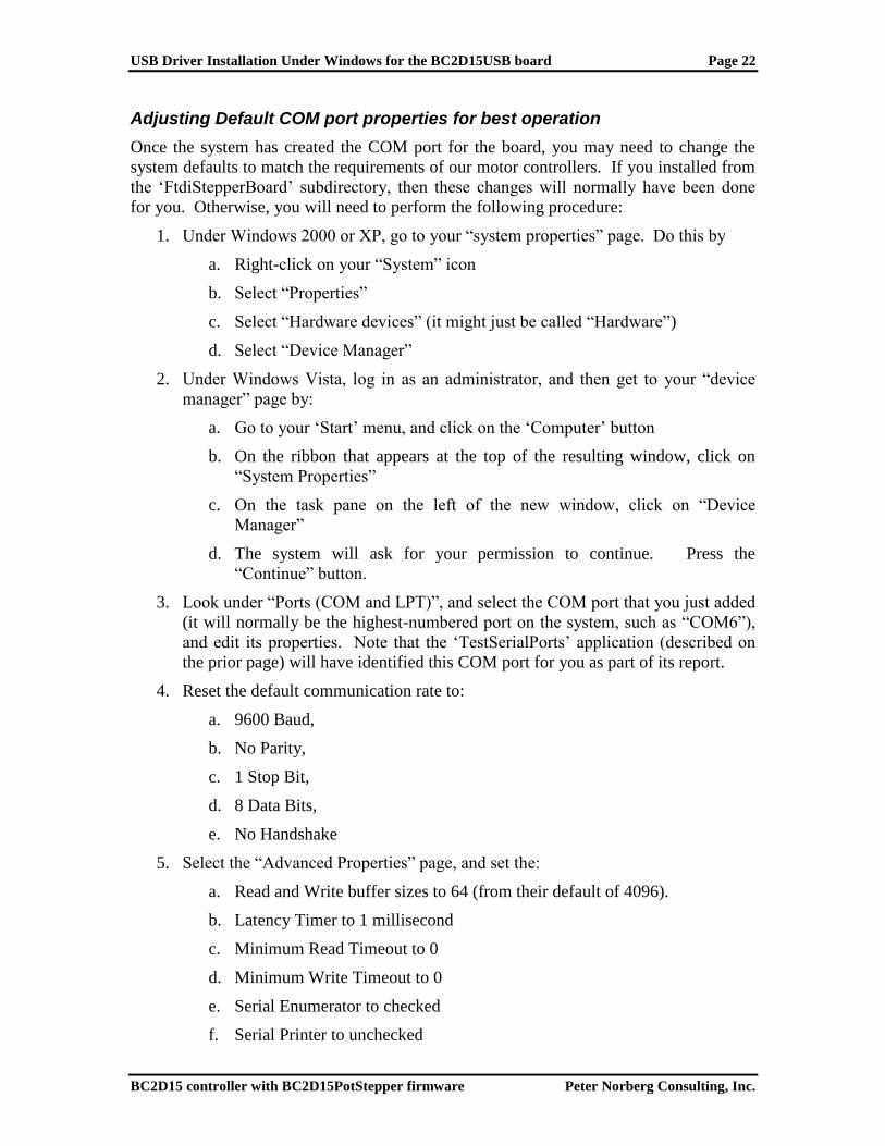
Adjusting Default COM port properties for best operation
Once the system has created the COM port for the board, you may need to change the
system defaults to match the requirements of our motor controllers. If you installed from
the „FtdiStepperBoard‟ subdirectory, then these changes will normally have been done
for you. Otherwise, you will need to perform the following procedure:
1. Under Windows 2000 or XP, go to your “system properties” page. Do this by
a. Right-click on your “System” icon
b. Select “Properties”
c. Select “Hardware devices” (it might just be called “Hardware”)
d. Select “Device Manager”
2. Under Windows Vista, log in as an administrator, and then get to your “device
manager” page by:
a. Go to your „Start‟ menu, and click on the „Computer‟ button
b. On the ribbon that appears at the top of the resulting window, click on
“System Properties”
c. On the task pane on the left of the new window, click on “Device
Manager”
d. The system will ask for your permission to continue. Press the
“Continue” button.
3. Look under “Ports (COM and LPT)”, and select the COM port that you just added
(it will normally be the highest-numbered port on the system, such as “COM6”),
and edit its properties. Note that the „TestSerialPorts‟ application (described on
the prior page) will have identified this COM port for you as part of its report.
4. Reset the default communication rate to:
a. 9600 Baud,
b. No Parity,
c. 1 Stop Bit,
d. 8 Data Bits,
e. No Handshake
5. Select the “Advanced Properties” page, and set the:
a. Read and Write buffer sizes to 64 (from their default of 4096).
b. Latency Timer to 1 millisecond
c. Minimum Read Timeout to 0
d. Minimum Write Timeout to 0
e. Serial Enumerator to checked
f. Serial Printer to unchecked

USB Driver Installation Under Windows for the BC2D15USB board Page 23
BC2D15 controller with BC2D15PotStepper firmware Peter Norberg Consulting, Inc.
g. Cancel If Power Off to unchecked
h. Event On Surprise Removal to unchecked
i. Set RTS On Close to unchecked
(that is to say, only the Serial Enumerator is checked in the set of check boxes on the
display)
Serial Operation Page 24
BC2D15 controller with BC2D15PotStepper firmware Peter Norberg Consulting, Inc.
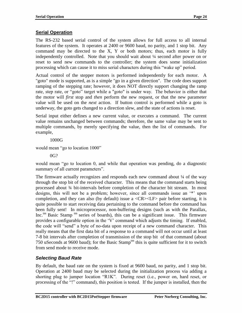
Serial Operation
The RS-232 based serial control of the system allows for full access to all internal
features of the system. It operates at 2400 or 9600 baud, no parity, and 1 stop bit. Any
command may be directed to the X, Y or both motors; thus, each motor is fully
independently controlled. Note that you should wait about ¼ second after power on or
reset to send new commands to the controller; the system does some initialization
processing which can cause it to miss serial characters during this “wake up” period.
Actual control of the stepper motors is performed independently for each motor. A
"goto" mode is supported, as is a simple "go in a given direction". The code does support
ramping of the stepping rate; however, it does NOT directly support changing the ramp
rate, step rate, or “goto” target while a "goto" is under way. The behavior is either that
the motor will first stop and then perform the new request, or that the new parameter
value will be used on the next action. If button control is performed while a goto is
underway, the goto gets changed to a direction slew, and the state of actions is reset.
Serial input either defines a new current value, or executes a command. The current
value remains unchanged between commands; therefore, the same value may be sent to
multiple commands, by merely specifying the value, then the list of commands. For
example,
1000G
would mean “go to location 1000”
0G?
would mean “go to location 0, and while that operation was pending, do a diagnostic
summary of all current parameters”.
The firmware actually recognizes and responds each new command about ¼ of the way
through the stop bit of the received character. This means that the command starts being
processed about ¾ bit-intervals before completion of the character bit stream. In most
designs, this will not be a problem; however, since all commands issue an „*‟ upon
completion, and they can also (by default) issue a <CR><LF> pair before starting, it is
quite possible to start receiving data pertaining to the command before the command has
been fully sent! In microprocessor, non-buffering designs (such as with the Parallax,
Inc.tm
Basic Stamp tm
series of boards), this can be a significant issue. This firmware
provides a configurable option in the „V‟ command which adjusts the timing. If enabled,
the code will “send” a byte of no-data upon receipt of a new command character. This
really means that the first data bit of a response to a command will not occur until at least
7-8 bit intervals after completion of transmission of the stop bit of that command (about
750 uSeconds at 9600 baud); for the Basic Stamptm
this is quite sufficient for it to switch
from send mode to receive mode.
Selecting Baud Rate
By default, the baud rate on the system is fixed at 9600 baud, no parity, and 1 stop bit.
Operation at 2400 baud may be selected during the initialization process via adding a
shorting plug to jumper location “R1K”. During reset (i.e., power on, hard reset, or
processing of the “!” command), this position is tested. If the jumper is installed, then the

Serial Operation Page 25
BC2D15 controller with BC2D15PotStepper firmware Peter Norberg Consulting, Inc.
baud rate is set to 2400 baud. If it is left open (the default), then the baud rate is set to
9600 baud.
Serial Commands
The serial commands for the system are described in the following sections. The code is
case-insensitive (i.e., “s” means the same thing as “S”). Please be aware that any time
any new input character is received, any pending output which has not actually started
transmission (such as the standard “*” response to a prior command, or the more
complex output from a report) is cancelled. This avoids loss of commands as they are
being sent to the control board.
Serial Command Quick Summary
Most of the commands may be preceeded with a number, to set the value for the
command. If no value is given, then the last value seen as any form of input
parameter is used.
0-9, +, - – Generate a new VALUE as the parameter for all FOLLOWING commands
A – Select the Auto-Full Power Step Rate
B – Select both motors
C – Set port „C‟ values: Used to set IO6 and O7 levels
E – Enable or Disable Remote Direct Pulse Control
G – Go to position x on the current motor(s)
H – Operate motors at given power
I – Wait for motor „Idle‟
K –Set the "Stop oK" rate
L – Latch Report: Report current latches, reset latches to 0
M – Mark location, or go to marked location
O – step mOde – How to update the motor windings
P – sloPe (number of steps/second that rate may change)
R – Set run Rate target speed for selected motor(s)
S – start Slew
T – limiT switch and IO6/IO7 control
V – Verbose mode command synchronization
W – Set windings power levels when motor is idle
X – Select motor X
Y – Select motor Y
Z – Stop current motor
! – RESET – all values cleared, all motors set to "free" (i.e., idle current), redefine microstep.
Duplicates Power-On Conditions! Note that if your particular board has been configured
with a non-0 default idle current (special order option), then the motors will be instantly
“locked” using that winding current!
= – Define current position for the current motor to be 'x', stop the motor
? – Report status
other – Ignore, except as "complete value here"

Serial Operation Page 26
BC2D15 controller with BC2D15PotStepper firmware Peter Norberg Consulting, Inc.
0-9, +, - – Generate a new VALUE as the parameter for all FOLLOWING commands
Possible combinations:
"-" alone – Set '-' seen, set no value yet: used on SLEW -
"+" alone – Clear '-' seen, set no value yet: used on SLEW+
-n: Value is treated as -n
n: Value is treated as +n
+n: Value is treated as +n
Examples:
-s – Start slew in „-„ direction on the current motor
-10s – Slew back 10 steps on the current motor
A – Select the Auto-Full Power Step Rate
This sets the approximate rate (expressed in the current microstep resolution; see the
“!” command) at which the system automatically switches to full step mode. This is
used once the power loss induced by changing the reference currents at high speed
becomes significant.
Note that the code only stores the high byte of this value (i.e., the value divided by
256), and requires that the actual rate divided by 256 be above the value just set. This
means that “A” rates of 0-255 all map into 0, and they set all rates 256 and above to
be auto-full step mode. The code defaults at power-on/reset to A=10000
(“10000a”), which causes switching to full-step mode at about the rate of 10000
microsteps/second.
Set this to 44801 to disable this feature.

Serial Operation Page 27
BC2D15 controller with BC2D15PotStepper firmware Peter Norberg Consulting, Inc.
B – Select both motors
This command selects both the X and Y motors as targets for the following
commands.
For example,
B0?
Would generate a report about all reportable parameters for both motors.
At power on/reset, both motors are selected for actions.
C – Set port „C‟ values: used to set IO6 and IO7 levels
The „C‟ command is used to set the output levels for the IO6 and IO7 signals, after
they have been configured as output signals (see the „T‟ command, T – limiT switch
and IO6/IO7 control). As with the „T‟ command, only bits 6 and 7 are actually sent
to IO6 and IO7 (respectively); therefore the acceptable settings are:
0C Set IO6 and IO7 both low
64C Set IO6 high, IO7 low
128C Set IO6 low, IO7 high
192C Set IO6 high, IO7 high
Note that any other bits in the data are ignored; however, it is better practice to just
use the above values, to remain compatible with future firmware releases.
If a given IO line is defined as an input, then this command is ignored for that
particular signal (i.e. “64C” will not force IO6 to be high if IO6 is defined as an
input).

Serial Operation Page 28
BC2D15 controller with BC2D15PotStepper firmware Peter Norberg Consulting, Inc.
E – Enable or Disable Remote Direct Pulse Control
This is used to control whether the TTL input lines are used as direct, edge triggered
step requests for their associated motor and direction of travel. The current VALUE
is used as the parameter. The options are bit encoded into the value; the low 4 bits of
value define the main Pulse Control mode, while the next higher 4 bits control the
interpretation of the input signal level. The defined values for the low 4 bits are:
0e – Disable remote pulse control (the power on/reset default). Note that the
entire value must be 0 for remote pulse control to be disabled – if you define
any of bits 4-7 (the signal level bits) to be non-0, then the code will act as if
step mode „1‟ was selected.
1e – Enable remote pulse control, with each line being its own step/direction
2e – Enable “Step/Direction” mode of direct pulse control: the “-“ inputs are
treated as direction, the “+” inputs are treated as step requests.
Bits 4-7 are used to control the interpretation of the signal levels. When set to 0 (the
default), then the signals are interpreted as described below. When set to 1, then the
given signal is inverted (i.e., “0” is mapped into “1”, and “1” is mapped into “0”).
The net effect of this is to change the edge which triggers the motion from the low-
going edge to the high-going edge, and to flip (when in mode 2) the interpretation of
the direction of travel.
The bits are encoded as follows:
Bit Value Signal
Inverted
4 +16 Y-
5 +32 Y+
6 +64 X-
7 +128 X+
For example, to operate in the Step/Direction mode of operation, with high-going
pulses requesting the steps on both the X and Y motors, you would use a value of
2+32+128 (since the Y+ and X+ input signals are used as the step requests, and need
to be inverted so that the high-going edge triggers). Therefore, the command given
would be “162e”.
On both enable and disable, all pending motor actions are immediately stopped. The
windings on both motors are forced on when remote pulse control is enabled, and are
restored to the status defined by the W command when remote pulse control is
disabled.

Serial Operation Page 29
BC2D15 controller with BC2D15PotStepper firmware Peter Norberg Consulting, Inc.
NOTE THAT:
THIS COMMAND IS FOR BOTH MOTORS
IT IMMEDIATELY DISABLES ANY PENDING MOTIONS
IF ANY MOTION IS UNDER WAY, THAT FACT IS FORGOTTEN.
THIS CAUSES AN INSTANT STOP OF BOTH MOTORS! NO
“GRADUAL STOP” (VIA THE AUTOMATIC RAMP MECHANISM)
IS PERFORMED. MOTORS OR GEAR TRAINS MAY THUS BE
DAMAGED IF THIS IS DONE IMPROPERLY ON SOME SYSTEMS.
TTL INPUTS FOR LIMIT SWITCHES ARE ALSO IGNORED
DURING THIS MODE OF OPERATION.
TTL INPUTS ARE TREATED AS “SCHMITT-TRIGGERED”
DURING THIS MODE: <=0.4 Volts is “0”, >=4.6 volts is “1”.
When enabled, then all other motor motion commands (such as G and S) have no
effect (although changing the step mode, marking locations, and setting rates will
affect the stored values for use when remote direct control is disabled). Instead, the
TTL input lines are monitored frequently enough to sense 8 microsecond width
pulses, looking for low-going-edges (leading edges) in the requests. The leading
edges are then used to step the appropriate motor as needed. The stepping actions
performed are always in units of the current microstep size, and are masked based on
the current winding control rules (see the “!” command for how to control the
microstep size, and the “O” command for control of winding/microstepping).
This mode monitors the TTL inputs very closely. It looks for leading (low-going)
edges on each of the 4 TTL input lines (low means TRUE, high means FALSE, for
compatibility with the normal switch mode of input), and issues a single microstep (in
the current microstep precision). The rate of monitoring is such that, if pulses are 8
microseconds wide for each of the high and low states, they will be correctly sensed.
Pulse widths less than 8 microseconds will usually be incorrectly processed! The
effective maximum stepping rate is therefore 16 microseconds per microstep (both
motors may be stepped at the same time), thus providing for a maximum step rate of
44,801 microsteps per second per motor. Since the maximum microstep rate is ½
full step per microstep, the maximum rate possible with this form of control is 31,250
full steps per second.
If mode 1 is used, then each input line („x-‟, „x+‟, „y-‟, „y+‟) is independently
monitored for pulse edges, and is used to request a single step in the indicated
direction.
If mode 2 is used, then each input line pair is used to control step and direction. „x-‟
and „y-‟ are used to determine the direction the indicated motor will spin on an
associated step request (low means spin minus, high means spin plus). The „x+‟ and
„y+‟ inputs are monitored for the related step requests: a low-going edge on the
indicated line generates a step request on the associated motor. The restriction of
timing is that each direction line („x-‟ or „y-‟) must be stable at least 20 ns before the
low-going edge of the associated step line („x+‟ or „y+‟), and must remain stable for
at least 8 microseconds.

Serial Operation Page 30
BC2D15 controller with BC2D15PotStepper firmware Peter Norberg Consulting, Inc.
G – Go to position x on the current motor(s)
This is used to cause the currently selected motor(s) to travel to the indicated location
(from the current Value). The software will:
Calculate the direction and distance of travel
Determine how long it has to „ramp‟ the motor to go from its current start rate
(the „K‟ value) to the standard target rate (the „R‟ value) using the current
ramp rate (the „P‟ value)
Determine how long it has to then let the motor run at the target stepping rate
Determine how long it will need to ramp the motor to stop it (which is the
same time as that for starting the motor, above).
Actually perform the action
The code ALWAYS starts from a stop, due to issues of timing. Therefore, if a
“Goto” is performed while the motor is running, the system will first stop the motor
(as in the „Z‟ command), and then restart it based on its then-current location.
For example,
X1000gy-25687g
Would:
1. Select the X motor for actions
2. Start a GOTO on motor X to location 1000
3. Select motor Y for actions
4. Start a GOTO on motor Y to location –25687
Note that the two goto operations continue asynchronously until completed, unless a
new command (such as a stop for that motor, or a change in direction request) is
received. The current location for a given motor may always be requested, through
the “-1” report. For example,
x-1?
Could report
X,-1,350
*
while the motor was still on its way to the requested location.

Serial Operation Page 31
BC2D15 controller with BC2D15PotStepper firmware Peter Norberg Consulting, Inc.
H – Specify Motor Current When Moving
“H” is used to specify the motor current to use when motor motion is under way. A
separate current may be specified for each motor. At power-on, the “H” value is set
to 220 (which is 1.3 amps of power), unless there is a shorting plug installed in
position “S1K”. In that case, the “H” value is set to 55, which sets the windings to ¼
of the power that the board can generate.
If H is set to 0, this fully disables the motor as no current will flow (the motor is
“free”).
Values for H that are below 23 are not reliable; this is what specifies the minimum
current that a given version of our board can generate.
The actual formula for determining the current delivered to the motor is
H = I*169
Thus, some commonly used values would be:
Current H value
0.25 43
0.32 55
0.5 84
0.75 127
1.0 169
1.3 220
1.5 255
Note that the actual current delivered is probably no more accurate than 10-20%.
Please note that the board is only rated for continuous duty at the 1.3 amp level. The
1.5 amp setting is fine for running motors for short durations of time (less than 30
seconds), with at least 30 seconds of idle time (current to the windings off) in
between motor motions.

Serial Operation Page 32
BC2D15 controller with BC2D15PotStepper firmware Peter Norberg Consulting, Inc.
I – Wait for motor „Idle‟
This allows your code to „wait‟ for the currently selected motor(s) to (both) be idle.
The code simply waits for either the selected motors to have completed their motion
(see the X, Y, and B commands) or for the next serial character to be received, and
then it transmits the „*‟ prompt (ready for next command). Note that, if the wait is
stopped by receipt of a new character, then the new character IS processed as part of a
new command – it is NOT discarded.
For example, to go to a given X location, and then wait for the motor to actually get
there, you could simply issue the command sequence:
Send Receive
X *
2000G * (note that the „*‟ is received as soon as the motion starts)
I * (note that this „*‟ is not received until the motion completes)
If you send a character before receipt of the final „*‟ (above), then system will discard
transmitting the “*” response if it has not yet started the transmission. It will then
process the new character. The best technique to avoid synchronization worries is to
send two zero characters („00‟), wait for the second one to be completely sent, and
then clear your input buffers. No further characters will be sent from the board until
it sees the next command after this „flushing‟ action (i.e., any pending data
transmissions will be aborted).
K –Set the "Start/Stop oK" rate
This defines the rate at which the motors are considered to be "stopped" for the
purposes of starting, stopping or reversing directions. It defaults to the default of „80‟
if a value of 0 is given.
When a motion starts, this rate is compared to the requested target rate. If the
requested target rate is less, then the target rate becomes the initial rate; otherwise,
this rate is used. The motor is then ramped up (using the current slope rate, see the
„P‟ command) to the requested target rate, and continues at that rate until it is time to
ramp back down in order to stop at the requested target location.
By default, this is preset to “80” upon startup of the system. This means that,
whenever a stop is requested, the motor will be treated as “stopped” when its stepping
rate is <= 80 microsteps (5 full steps) per second.
For example,
100k
sets the start/stop rates for the currently selected motor(s) to be 100 microsteps per
second. Any time the current rate is less than or equal to 100, the motor will have the
ability to stop instantly.
To set the rate such that the motors always immediately start and stop at the desired
rate („R‟) setting, issue the command:
44801K

Serial Operation Page 33
BC2D15 controller with BC2D15PotStepper firmware Peter Norberg Consulting, Inc.
This sets the „Stop oK‟ rate to the maximum possible step rate, and thus will prevent
all ramping behaviors of the code.
L – Latch Report: Report current latches, reset latches to 0
The “L”atch report allows capture of key short-term states, which may affect external
program logic. It reports the “latched” values of system events, using a binary-
encoded method. Once it has reported a given “event”, it resets the latch for that
event to 0, so that a new “L” command will only report new events since the last “L”.
The latched events reported are as follows: Bit Value Description
0 +1 Y- limit reached during a Y- step action
1 +2 Y+ limit reached during a Y+ step action
2 +4 X- limit reached during a X- step action
3 +8 X+ limit reached during a X+ step action
4 +16 System power-on or reset (“!”) has occurred
For example, after initial power on,
L
Would report
L,16
*
If you were then to do an X seek in the “-” direction, and you hit the “X-” limit, then
the next “L” command would report:
L,4
*
M – Mark location, or go to marked location.
Based on the current parameter value (x), the M command will either cause the
selected stepper(s) to record its'/their current position as the "marked" point, or will
cause the location to be treated as a "goto" command.
x=0 : Mark current location for a later "go to mark" request
x=1 : Go to last "marked" location

Serial Operation Page 34
BC2D15 controller with BC2D15PotStepper firmware Peter Norberg Consulting, Inc.
O – step mOde – How to update the motor windings
The windings of the motors can be updated in one of three ways, depending on this
step mode setting. By default, the code uses “micro step” mode set for 8 steps per
complete full step, and performs a near-constant-torque calculation for positions
between full step locations. The other modes include two full step modes and an
alternating mode. For the full step modes, one enables only 1 winding at a time (low
power), while the other enables 2 windings at a time (full power). The remaining
mode alternates between 1 and 2 windings enabled.
The values which control this feature are:
0 : Full Step, Single winding mode (1/2 power full steps)
1 : Half step mode (alternate single/double windings on – non constant torque)
2 : Full step, double winding mode (full power full steps). NOTE: This mode
is often unreliable at high speeds. You will usually attain a higher speed using
mode 1 than you will with mode 2.
3 : Microstep, as fine as 1/16th
step, constant-torque mode – This is the
power on/reset default stepping mode.
For example,
0o
sets the above ½ power full step mode, while
3o
sets the default microstep mode.
The “o” command does NOT affect the current step rates or locations; it only affects
how the windings are updated. For example, when operating in the 1/8th
step size, the
following rules are applied for the various modes.
0: Single winding full step mode: Exactly one winding will be on at a time,
and will be on at the selected current for the motor. The “real” physical
motor position (in full step units) therefore only updates once every 8
microsteps; thus the “full step” location will be the (microstep location)/8,
dropping the fractional part.
1: Half step mode: Alternates between having one and two windings on at a
time, thus causing the torque to vary at the half-step locations. The “real”
physical locations will be at half-step values, and hence the motor will
“move” once every 3 microsteps. The “full step” location will be the
(microstep location)/8, with fractions of 0 to 3/8 mapping into fractional
location 0, and 4/8 though 7/8 mapping into fractional location 0.5.
2: Double winding full step mode: Both windings are “on” (at the selected
motor current) at a time. As with mode 0, the “real” physical motor position
will actually only update once every 8 microsteps. The “full step” location
will be the (microstep location)/8, with the fractional part forced to 0.5.
Please note that double-winding mode is often not reliable at high speeds.

Serial Operation Page 35
BC2D15 controller with BC2D15PotStepper firmware Peter Norberg Consulting, Inc.
3: Microstep mode. The current through both windings are precision-
controlled, so that the microposition can be obtained. The physical motor
position expressed in full step units is the (microstep location/16).
P – sloPe (number of steps/second that rate may change)
This command defines the maximum rate at which the selected motor‟s speed is
increased and decreased. By providing a “slope”, the system allows items which are
connected to the motor to not be “jerked” suddenly, either on stopping or starting. In
some circumstances, the top speed at which the motor will run will be increased by
this capability; in all cases, stress will be lower on gear systems and motor
assemblies.
The slope can be specified to be from 1 through 44,801 microsteps per second per
second. If a value of 0 is specified, the code forces it to have a value of 8000. If a
value above 44,801 (or less than 0) is specified, the code will accept it, but will ramp
unreliably (i.e., do not do it!).
This value defaults at power-on or reset to 8000 microsteps per second per
second. Please note that changing this during a "goto" action will cause the stop at
the end of the goto to potentially be too sudden or too slow – it is better to first stop
any “goto” in progress, and then change this slope rate.
For example, if we currently have motor X selected, and it is at location 0, then the
sequence:
250p500r2000g
would cause the following actual ramp behaviors to occur:
1. The motor would start at its “stop oK” rate, such as 80 microsteps/second
2. It would accelerate to its target rate of 500 microsteps per second, at an
acceleration rate of 250 microsteps/second/second.
3. This phase would last for approximately 500/250 or about 2 seconds, and
would cover about 500 microsteps of distance.
4. It would then stay at the 500 microstep per second target rate until it was
about 500 microsteps from its target location, i.e., at location 1500 (which
would take another 2 seconds of time).
5. It would then slow down, again at a rate of 250 microsteps per second, until it
reached the stop oK rate. As with the acceleration phase, this would take
about 2 seconds.
6. The total distance traveled would be exactly 2000 microsteps, and the time
would be 2+2+2=6 seconds (actually, very slightly less).
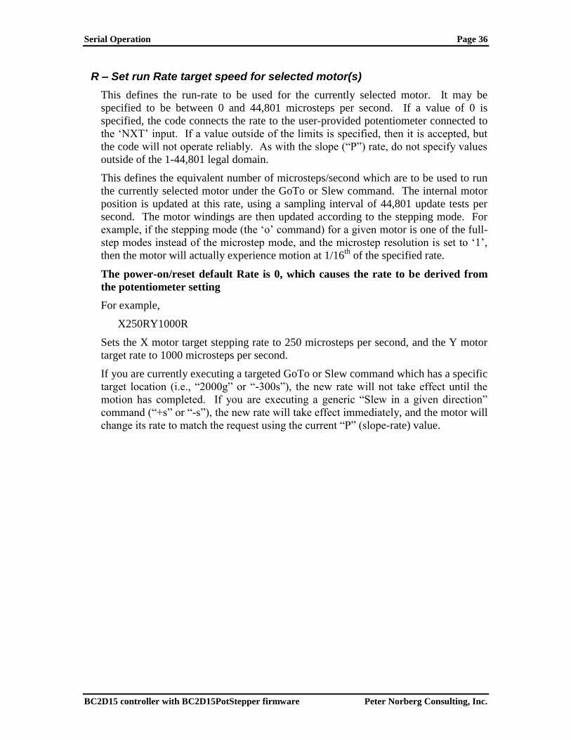
Serial Operation Page 36
BC2D15 controller with BC2D15PotStepper firmware Peter Norberg Consulting, Inc.
R – Set run Rate target speed for selected motor(s)
This defines the run-rate to be used for the currently selected motor. It may be
specified to be between 0 and 44,801 microsteps per second. If a value of 0 is
specified, the code connects the rate to the user-provided potentiometer connected to
the „NXT‟ input. If a value outside of the limits is specified, then it is accepted, but
the code will not operate reliably. As with the slope (“P”) rate, do not specify values
outside of the 1-44,801 legal domain.
This defines the equivalent number of microsteps/second which are to be used to run
the currently selected motor under the GoTo or Slew command. The internal motor
position is updated at this rate, using a sampling interval of 44,801 update tests per
second. The motor windings are then updated according to the stepping mode. For
example, if the stepping mode (the „o‟ command) for a given motor is one of the full-
step modes instead of the microstep mode, and the microstep resolution is set to „1‟,
then the motor will actually experience motion at 1/16th
of the specified rate.
The power-on/reset default Rate is 0, which causes the rate to be derived from
the potentiometer setting
For example,
X250RY1000R
Sets the X motor target stepping rate to 250 microsteps per second, and the Y motor
target rate to 1000 microsteps per second.
If you are currently executing a targeted GoTo or Slew command which has a specific
target location (i.e., “2000g” or “-300s”), the new rate will not take effect until the
motion has completed. If you are executing a generic “Slew in a given direction”
command (“+s” or “-s”), the new rate will take effect immediately, and the motor will
change its rate to match the request using the current “P” (slope-rate) value.

Serial Operation Page 37
BC2D15 controller with BC2D15PotStepper firmware Peter Norberg Consulting, Inc.
S – start Slew.
The “S”lew command is used to cause the currently selected motor to go in the
selected direction. If the current value is only “+” or “-” (i.e., just has a sign
associated with it), then the motor will slew in the indicated direction on the selected
motor(s). Otherwise, the motor(s) will go VALUE steps in the direction indicated by
the sign of VALUE, after first stopping the motor (more accurately, will target
current location + x, then act as goto).
For example,
+s
will cause the current motor to start slewing in the forward direction, while
-250s
will invoke the “relative seek” calculation mode of the firmware.
When doing a relative seek (i.e., “-250s”), the address calculations are normally based
on the current TARGET location, not the current instantaneous location. The actual
rules are as follows:
1. If the given motor is currently executing a GoTo or relative Seek command,
then the new location is calculated as a delta from the old target. For
example,
Current State:
Our current location is 1000
Our current target is 2000
We are doing a GoTo action
Request:
-500s
Calculation:
Since we are doing a normal GoTo,
the new target location will be "2000-500", or 1500
Result:
Motor stops, then goes forward to location 1500
2. Otherwise, the current location is treated as the value to calculate from for the
relative motion. For example,
Current State:
Our current location is 1000
We are executing a "+s" command (slew positive)
Request:
-500s
Calculation:
Since we are executing a Slew,
the new target location will be "1000-500", or 500
Result:
Motor stops, then goes backward to location 500
This was set up this way as being a reasonable compromise on the intent of the
meaning of "relative". If you want to force the motion to be strictly relative to the
current location, you issue the "z" (stop) command first. Once that has been issued,
the motor is placed in a special state (stopping, no target), which permits relative slew
to be from the current location.
For example, to go -500 steps from the current location, regardless of whether the
current action is a slew or a targeted goto, issue the command:
z-500s

Serial Operation Page 38
BC2D15 controller with BC2D15PotStepper firmware Peter Norberg Consulting, Inc.
T – limiT switch and IO6/IO7 control
The limi‟T‟ switch command is used to control interpretation of the board limit
switch input, and to control the direction of the IO6 and IO7 TTL lines. By default
(after power on and after any reset action), the board is configured to respond to
each of the four limit switches; that is to say, all of the limit switches are enabled. Additionally, the IO6 and IO7 lines are initially configured as inputs. Control of
this feature allows the board to more easily control rotary tables, which may only
have an “index” switch instead of a “left and right limit” switch.
The command takes a bit-encoded parameter, which lists which switches are to be
blocked from action. The values therefore are (as of firmware version 1.23):
Bit Numeric Sum
Value
Action
0 +1 Block Y-
1 +2 Block Y+
2 +4 Block X-
3 +8 Block X+
4 +16 Sense level, LY-
5 +32 Sense level, LY+
6 +64 Sense level, LX-
7 +128 Sense level, LX+
8 +256 Define direction for IO6:
If 0, set as input.
If 1, set as output
9 +512 Define direction for IO7:
If 0, set as input.
If 1, set as output
Other RESERVED – leave 0
The „Sense level‟ bits define whether the indicated limit input high or low value is
treated as “limit reached”. By default, the system operates based on assuming a 0
means „limit reached‟, so that no-connection to the inputs means “no limit is
associated with this motor going in this direction”.
For example,
4t
would block detection of the “X-” limit, and allow all of the other limits to work as
normal. It would also define IO6 and IO7 as inputs Similarly,
15t
would block detection of all limits (with IO6 and IO7 as inputs), and
256t
would enable detection of all limits, but would set IO6 as an output signal while
leaving IO7 as an input.
240t
would change all of the limit switch input polarities, so that HIGH is limit reached,
and LOW is not-at-limit. Note that if a given limit is left unattached, it will be treated
as “at the limit”.

Serial Operation Page 39
BC2D15 controller with BC2D15PotStepper firmware Peter Norberg Consulting, Inc.
Note that versions of the firmware prior to version 1.23 encoded this parameter
differently. Those versions did not support the capability of programming the sense
level for the limit inputs, thus the encoding was:
Bit Numeric Sum
Value
Action
0 +1 Block Y-
1 +2 Block Y+
2 +4 Block X-
3 +8 Block X+
4-5 RESERVED: LEAVE 0
6 +64 Define direction for IO6:
If 0, set as input.
If 1, set as output
7 +128 Define direction for IO7:
If 0, set as input.
If 1, set as output
Other RESERVED – leave 0
The equivalent examples as shown above (not including those showing the limit sense
level control) therefore become:
4t
would block detection of the “X-” limit, and allow all of the other limits to work as
normal. It would also define IO6 and IO7 as inputs Similarly,
15t
would block detection of all limits (with IO6 and IO7 as inputs), and
64t
would enable detection of all limits, but would set IO6 as an output signal while
leaving IO7 as an input.

Serial Operation Page 40
BC2D15 controller with BC2D15PotStepper firmware Peter Norberg Consulting, Inc.
V – Verbose mode command synchronization
The „V‟erbose command is used to control whether the board transmits a
“<CR><LF>” sequence before it processes a command, and whether a spacing delay
is needed before any command response. By default (after power on and after any
reset action), the board is configured to echo a carriage-return, line-feed
sequence to the host as soon as it recognizes that an incoming character is not
part of a numeric value. This allows host code to fully recognize that a command is
being processed; receipt of the <LF> tells it that the command has started, while
receipt of the final “*” states that the command has completed processing.
The firmware actually recognizes and starts to process each new command about ½ of
the way through the stop bit of the received character. This means that the command
starts being processed about ½ bit-interval before completion of the character bit
stream. In most designs, this will not be a problem; however, since all commands
issue an „*‟ upon completion, and they can also (by default) issue a <CR><LF> pair
before starting, it is quite possible to start receiving data pertaining to the command
before the command has been fully sent! In microprocessor, non-buffering designs
(such as with the Parallax, Inc.tm
Basic Stamp tm
series of boards), this can be a
significant issue. The firmware handles this via a configurable option in the „V‟
command. If enabled, the code will “send” a byte of no-data upon receipt of a new
command character. This really means that the first data bit of a response to a
command will not occur until at least 9 bit intervals after completion of transmission
of the stop bit of that command (about 900 uSeconds at 9600 baud); for the Basic
Stamptm
this is quite sufficient for it to switch from send mode to receive mode. The
firmware also adds 2 additional “stop” bits to each transmitted character, when this
feature is enabled. This is to allow non-buffering microprocessors some additional
time to do real-time input processing of the data.
The verbose command is bit-encoded as follows:
Bit SumValue Use When Set
0 +1 Send <CR><LF> at start of processing a new
command
1 +2 Delay about 1 character time before
transmission of first character of any command
response. On firmware versions 1.60 and later,
add 2 more stop bits to each transmitted
character, to allow more processing time in the
receiving microprocessor.
If you set verbose mode to 0, then the <CR><LF> sequence is not sent. Reports still
will have their embedded <CR><LF> between lines of responses; however, the initial
<CR><LF> which states that the command has started processing will not occur.
For example,
0v
would block transmission of the <CR><LF> command synch, and could respond
before completion of the last bit of the command, while
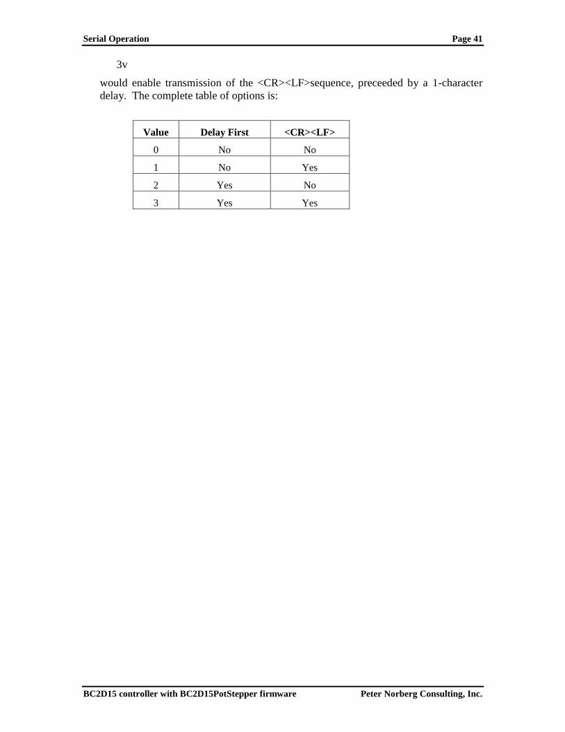
Serial Operation Page 41
BC2D15 controller with BC2D15PotStepper firmware Peter Norberg Consulting, Inc.
3v
would enable transmission of the <CR><LF>sequence, preceeded by a 1-character
delay. The complete table of options is:
Value Delay First <CR><LF>
0 No No
1 No Yes
2 Yes No
3 Yes Yes

Serial Operation Page 42
BC2D15 controller with BC2D15PotStepper firmware Peter Norberg Consulting, Inc.
W – Set windings power levels when motor is idle
“W” is used to specify the motor current to use when the motor is idle. A separate
current may be specified for each motor. At power-on, the “W” value is set to 0,
which disables the windings when motion is complete.
Values for W that are below 23 are not reliable, although values down to 1 will
usually be good enough for use with the „W‟ command. This is what specifies the
minimum current that a given version of our board can generate. For values below
23, the actual current provided will be significantly above that shown in the following
table. Lower values of W will have larger errors.
The actual formula for determining the current delivered to the motor is
H = I*169
Thus, some commonly used values would be:
Current H value
0.5 84
0.75 127
1.0 169
1.3 220
Note that the actual current delivered is probably no more accurate than 10-20% of
the calculated value.
X – Select motor X
This command selects X motor as the target for the following commands.
For example,
X100r
Would cause the step rate to be set to 100 for motor X.
Y – Select motor Y
This command selects Y motor as the target for the following commands.
For example,
Y100r
Would cause the step rate to be set to 100 for motor Y.

Serial Operation Page 43
BC2D15 controller with BC2D15PotStepper firmware Peter Norberg Consulting, Inc.
Z – Stop current motor.
„Z‟ causes the current motor(s) to be ramped to a complete stop, according to its
current ramp rate and stepping rate. “Stopped” is defined as “having a step rate
which is <= the stop oK rate”. See the „K‟ command for defining the “stop oK rate”.
For example,
Xz
Would slow down, then stop motor X.

Serial Operation Page 44
BC2D15 controller with BC2D15PotStepper firmware Peter Norberg Consulting, Inc.
! – RESET – all values cleared, all motors set to "free", redefine microstep. Duplicates Power-On Conditions!
This command acts like a power-on reset. It IMMEDIATELY stops both motors,
and clears all values back to their power on defaults. No ramping of any form is done
– the stop is immediate, and the motors are left in their “windings disabled” state.
This can be used as an emergency stop, although all location information will be lost.
The value passed is used as the new microstep size, in fixed 1/16th
of a full step units.
At raw power on, the board acts like a “1!” has been requested; that is to say, it
sets the microstep size to 1x1/16, which is 1/16th
of a full step. By issuing the „!‟
command, you can redefine the microstep size to a value convenient for your
application. The value must range from 1 to 16; it is clipped to this range if
exceeded.
The suggested values would be the powers of 2, vis. 1, 2, 4, 8, and 16 (giving you true
microstep step sizes of 1/16, 1/8, ¼, ½ and 1 respectively). All other values (such as
RATE or GOTO LOCATION) are then expressed in units of the microstep size;
therefore, location “3” would mean “3/16” in the finest resolution (microstep set to
1), and “3” in the largest resolution (microstep set to 16).
For example,
1!
resets the system to its power on default of 1/16 microstep resolution.
The reset command also selects the following settings:
10000A – Set the Automatic Full Step rate to be 10000 microsteps/second.
B – Select both motors for the following actions
0= – Define both motors to be at location 0
220H – Set motors to 1.3 amps of power (will reset to 55 (0.32 amps) if ¼
power mode is selected through use of the „S1K‟ jumper)
80K – Set the “Stop OK” rate to 80 microsteps/second
3O – Set the motor windings Order to “microstep”
8000P – Set the rate of changing the motor speed to 8000
microsteps/second/second
800R – Set the target run rate for the motor to 800 microsteps/second
0T – Enable all limit switch detection, set the IO6 and IO7 TTL lines to act as
inputs
1V – Set <CR><LF> sent at start of new command, no transmission delay
time
0W – Windings are off (no current) during motor idle

Serial Operation Page 45
BC2D15 controller with BC2D15PotStepper firmware Peter Norberg Consulting, Inc.
= – Define current position for the current motor to be 'x', stop the motor
This copies the current VALUE as the current position for the selected motors, and
then stops said motor(s). For example,
X2000=Y4000=
Would define the current location of the X motor to be 2000, and the current location
of the Y motor to be 4000. Note that no actual motor motion is involved – the code
simply defines the current location to be that found in the VALUE register, and issues
an automatic stop („Z‟) request. Note that the motor is stopped AFTER the
assignment is complete, so the actual “current position” of the motor will be different
from this value, depending on how long it takes for the motor to stop.
X2000=g
Would define the current location of the X motor to be 2000, and then would actually
go to that 2000 location. This combination could be used when the motor is actually
slewing or executing a “goto”, to force the “current” location to be set and selected.

Serial Operation Page 46
BC2D15 controller with BC2D15PotStepper firmware Peter Norberg Consulting, Inc.
? – Report status
The “Report Status” command (“?”) can be used to extract detailed information about
the status of either motor, or about internal states of the software.
For a status report, the value is interpreted as from one of three groups:
1-255: Report memory location 1-255
Useful locations: NOTE THAT ANY LOCATION ABOVE 7 MAY CHANGE
BETWEEN CODE VERSIONS
5: Port A register – this contains the limit switches
6: Port B register – this contains the TTL inputs
7: Port C register – this controls the motor windings. Note that bits 6 and 7 (+64
and +128 respectively) are the signals labeled IO6 and IO7 on the extra TTL
logic connector at the top of the board.
0: Report all of the following special reports except for version/copyright
-1 to -12: Do selected one of the following reports
-1; Report current location
-2; Report current speed
-3; Report current slope
-4; report target position
-5; Report target speed
-6; Report windings state
-7; report stop windings state
-8; Report step action (i.e., motor state)
-9; Report step style
-10; Report run rate
-11; Report stop rate
-12; Report current software version and copyright
other: Treat as 0 (report all except version/copyright)

Serial Operation Page 47
BC2D15 controller with BC2D15PotStepper firmware Peter Norberg Consulting, Inc.
All of the reports follow a common format, of:
1. If Verbose Mode is on, then a <carriage return><line feed> (“crlf”) pair is
sent.
2. The letter corresponding to the motor being reported on is sent (i.e., „X‟ or
„Y‟).
3. A comma is sent.
4. The report number is sent (such as –4, for target position).
5. Another comma is sent.
6. The requested value is reported.
7. If this is a report for both the X and the Y motors, then a <crlf> is sent.
8. If this is a report for both motors, the other report is sent.
9. If Verbose Mode is on, then a <crlf> is sent
10. A “*” character is sent.
If both motors are being reported, a line containing the X report is sent, followed by a
line containing the Y report.
Finally, a “*” character is sent, which notifies the caller that the report is complete.
Note that in the following examples, first line of “Received” is “*”. This is because
two commands are actually being sent (i.e., “B”, then “-<whatever>?”), and each
command always generates a “*” response once it has been completed. Technically,
fully “synchronized” serial communication consists of (1) send a command, and (2)
save all characters until the “*” response is seen. The intervening characters are the
results of the command, although only report (“?”) and reset (“!”) generate any
significant response.
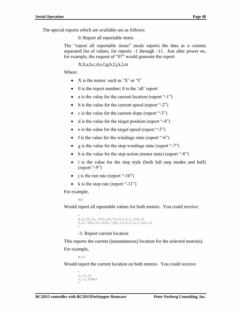
Serial Operation Page 48
BC2D15 controller with BC2D15PotStepper firmware Peter Norberg Consulting, Inc.
The special reports which are available are as follows:
0: Report all reportable items
The “report all reportable items” mode reports the data as a comma
separated list of values, for reports –1 through –11. Just after power on,
for example, the request of “0?” would generate the report:
X,0,a,b,c,d,e,f,g,h,I,j,k,l,m
Where:
X is the motor: such as „X‟ or „Y‟
0 is the report number; 0 is the „all‟ report
a is the value for the current location (report “-1”)
b is the value for the current speed (report “-2”)
c is the value for the current slope (report “-3”)
d is the value for the target position (report “-4”)
e is the value for the target speed (report “-5”)
f is the value for the windings state (report “-6”)
g is the value for the stop windings state (report “-7”)
h is the value for the step action (motor state) (report “-8”)
i is the value for the step style (both full step modes and half)
(report “-9”)
j is the run rate (report “-10”)
k is the stop rate (report “-11”)
For example,
B0?
Would report all reportable values for both motors. You could receive: *
X,0,30,10,1000,30,10,0,0,0,1,100,10
Y,0,-300,10,1000,-300,10,0,0,0,1,100,10
*
-1: Report current location
This reports the current (instantaneous) location for the selected motor(s).
For example,
B-1?
Would report the current location on both motors. You could receive:
*
X,-1,10
Y,-1,25443
*

Serial Operation Page 49
BC2D15 controller with BC2D15PotStepper firmware Peter Norberg Consulting, Inc.
-2: Report current speed
This reports the current (instantaneous) speed for the selected motor(s).
For example,
B-2?
Would report the current speed on both motors. You could receive:
*
X,-2,800
Y,-2,2502
*
-3: Report current slope
This reports the current (instantaneous) rate of changing the speed for the
selected motor(s).
For example,
B-3?
Would report the current rate on both motors. You could receive:
*
X,-3,10
Y,-3,25443
*
-4: Report target position
This reports the target location for the selected motor(s).
For example,
B-4?
Would report the current target on both motors. You could receive:
*
X,-4,100
Y,-4,-35443
*
-5: Report target speed
This reports the current target run rate which is desired for the selected
motor(s). This value is usually either the current stop rate (we are
attempting to slow down to this speed) or the current requested run rate (as
reported by –10, and as requested by the „R‟ command) depending on
whether we are speeding up or slowing down.
For example,
B-5?
Would report the target rate on both motors. You could receive:
*
X,-5,800
Y,-5,250
*
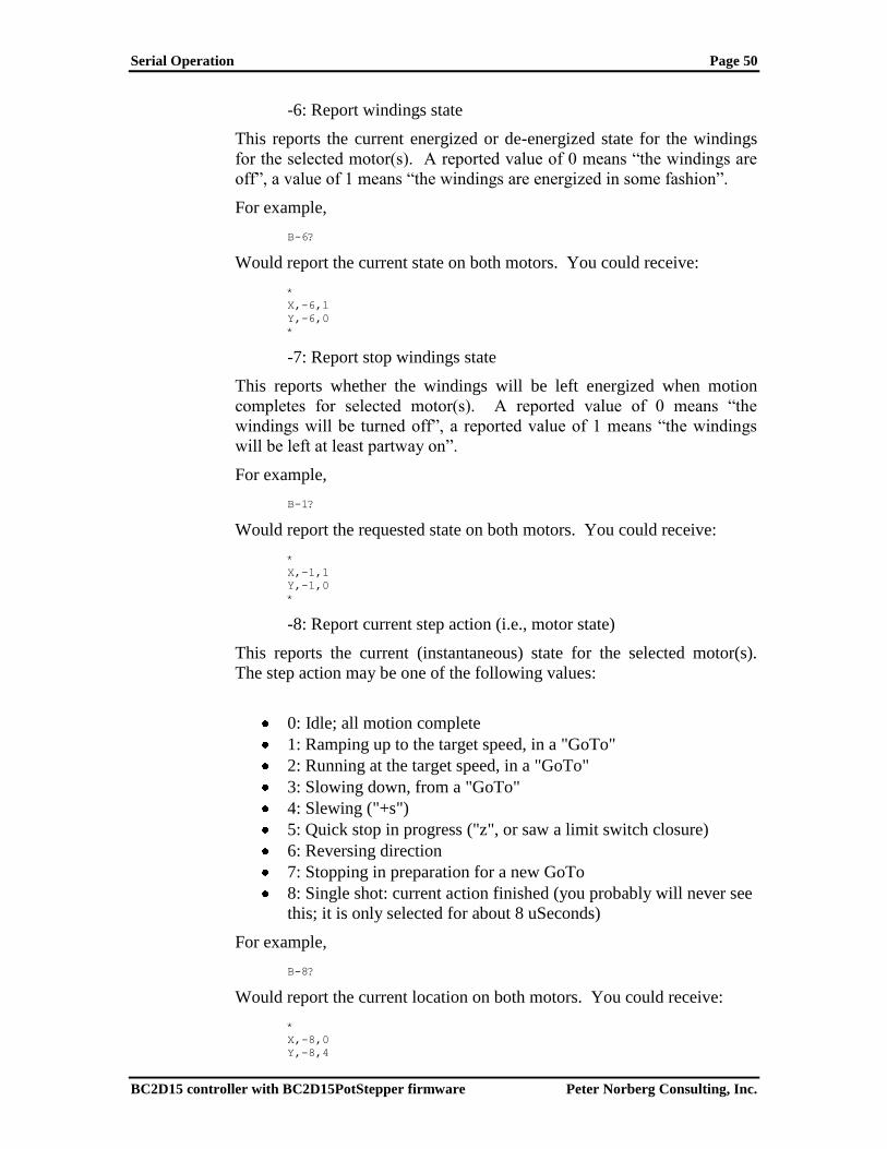
Serial Operation Page 50
BC2D15 controller with BC2D15PotStepper firmware Peter Norberg Consulting, Inc.
-6: Report windings state
This reports the current energized or de-energized state for the windings
for the selected motor(s). A reported value of 0 means “the windings are
off”, a value of 1 means “the windings are energized in some fashion”.
For example,
B-6?
Would report the current state on both motors. You could receive:
*
X,-6,1
Y,-6,0
*
-7: Report stop windings state
This reports whether the windings will be left energized when motion
completes for selected motor(s). A reported value of 0 means “the
windings will be turned off”, a reported value of 1 means “the windings
will be left at least partway on”.
For example,
B-1?
Would report the requested state on both motors. You could receive:
*
X,-1,1
Y,-1,0
*
-8: Report current step action (i.e., motor state)
This reports the current (instantaneous) state for the selected motor(s).
The step action may be one of the following values:
0: Idle; all motion complete
1: Ramping up to the target speed, in a "GoTo"
2: Running at the target speed, in a "GoTo"
3: Slowing down, from a "GoTo"
4: Slewing ("+s")
5: Quick stop in progress ("z", or saw a limit switch closure)
6: Reversing direction
7: Stopping in preparation for a new GoTo
8: Single shot: current action finished (you probably will never see
this; it is only selected for about 8 uSeconds)
For example,
B-8?
Would report the current location on both motors. You could receive:
*
X,-8,0
Y,-8,4

Serial Operation Page 51
BC2D15 controller with BC2D15PotStepper firmware Peter Norberg Consulting, Inc.
*
This would mean that motor X is idle, while motor Y is currently doing
some form of slew operation.
-9: Report step style (i.e., micro step, half, full)
This reports the current method of stepping for the selected motor(s). The
valid step styles reported are those of the “O” (step mode) command, vis:
0: Full step, single windings
1: Half step, alternating single/double windings
2: Full step, double windings
3: Microstep
For example,
B-9?
Would report the current stepping method on both motors. You could
receive:
*
X,-9,3
Y,-9,2
*
This would equate to the X motor being in microstep mode, while the Y
motor is running in full-power, full step mode.
If you were connected in dual power mode, then you could get a report
such as:
*
X,-9,7
Y,-9,6
*
Even though a mode will be reported for the Y motor controller, it is
actually ignored in terms of sending signals to the Y motor connector;
only the X motor controller affects the signals sent to the X and Y
connectors when in dual power mode.
-10: Report run rate
This reports the current requested run rate for the selected motor(s). This
is the last value set by the “R” command.
For example,
B-10?
Would report the current rate on both motors. You could receive:
*
X,-10,2000
Y,-10,3200
*
-11: Report stop rate

Serial Operation Page 52
BC2D15 controller with BC2D15PotStepper firmware Peter Norberg Consulting, Inc.
This reports the speed at which the motors may be considered to be
stopped, for starting and stopping activities for the selected motor(s).
For example,
B-11?
Would report the current stop rate on both motors. You could receive:
*
X,-11,80
Y,-11,50
*
-12: Report current software version and copyright
This reports the software version and copyright.
For example,
B-12?
could report:
*
BCPotStepper.src $version: 1.48$
Copyright 2002 by Peter Norberg Consulting, Inc. All Rights
Reserved
*
other – Ignore, except as "complete value here"
Any invalid command is simply ignored, other than sending a response of “*”.
However, if a numeric input was under way, that value will be treated as complete.
For example,
123 456G
would actually request a “GoTo location 456”. Since the “ ” command is invalid, it is
ignored; however, it terminates interpretation of the value which had been started as
123.
Note that, upon completion of ANY command (including the „ignored‟ commands),
the board sends the <carriage return><line feed> pair, followed by the “*” character
(as configured by the „V‟ command).

Serial Operation Page 53
BC2D15 controller with BC2D15PotStepper firmware Peter Norberg Consulting, Inc.
More Examples
For example,
Y 1000 R
Would set the Y rate to 1000 steps/second. The spaces are optional, and
would not prevent the code from working; however, an extra “<cr><lf>*”
sequence would be sent by the board for each space seen.
B50R
Would set both the Y and X rates to 50 steps per second
300YG
Would go to Y location 300
800G
Would go to location 800 on the most recent motor (in this example, Y)
Y-S
Would start slewing in the minus direction on Y motor
Y+SX3S
Would start slewing positive on Y motor, and would go + 3 steps on the X
motor
X1SSS
Would step forward 3 steps on the Y motor, since the calculation is based
on the CURRENT TARGET location at the time of the command if the
motor is currently executing a GOTO or relative step slew, and is
otherwise based on the current MOTOR location. This is thus exactly
equivalent to
X3s
X100rY300RB0g
Would cause the step rate to be set to 100 for motor X, 300 for motor Y,
and then cause both motors to go to location 0.

Serial Operation Page 54
BC2D15 controller with BC2D15PotStepper firmware Peter Norberg Consulting, Inc.
Use of the IO6 and IO7 TTL signals
The BC2D15 series of boards provides 2 extra TTL I/O signals called “IO6” and “IO7”
which can be individually programmed through use of serial commands to be inputs or
outputs.
When they are programmed as inputs, they have an internal weak pullup resistor attached
from the signal to +5 (about 10-30K ohms). This allows use of a simple switch-closure-
to-ground technique as being the signal source; however, they may also be connected to
standard TTL signal sources (the 10K pullup will not interfere with TTL signal levels).
The system accepts 0 to 2 volts as a “0”, and 3 to 5 volts as a “1”. Signals in the range of
2 to 3 volts are undefined, and will be randomly reported as “0” or “1”.
When programmed as outputs, these may drive at most a 10 mA load, as a TTL output
(<0.6 volts low, >4.2 volts high).
The „T‟ command is used to control limit switch behavior, and to define the Input/Output
definitions of the IO6 and IO7 lines. Its values are bit encoded as:
Bit Numeric Sum
Value
Action
0 +1 Block Y-
1 +2 Block Y+
2 +4 Block X-
3 +8 Block X+
4-5 +16, +32 RESERVED – leave 0
6 +64 Define direction for IO6:
If 0, set as input.
If 1, set as output
7 +128 Define direction for IO7:
If 0, set as input.
If 1, set as output
Other RESERVED – leave 0
Please see the „T‟ command (T – limiT switch and IO6/IO7 control) for more information
about this command.
In order to read the data from IO6 and IO7, you issue the “7?” generic report command.
This will give you back a bit-encoded report; you ignore the low 6 bits (bits 0-5), and just
look at bits 6 and 7. This means that:
0-63 – Means IO6 and IO7 are both low
64-127 – Means IO6 is high, IO7 is low
128-191 – Means IO6 is low, IO7 is high
192-255 – Means IO6 is high, IO7 is high
If you have used the „T‟ command to configure IO6 or IO7 as outputs, then you may use
the „C‟ command (C – Set port „C‟ values: used to set IO6 and IO7 levels) to define the
output levels. Note that when you first issue the T command to define a line as being
output which was an input, the initial level (before you issue the „C‟ command) will be
that seen on the port when treated as an input. Since the code sets the ports to have a 10-
30K pullup when used as inputs, this usually means that the initial output value will be
high.

Direct TTL Step Control Page 55
BC2D15 controller with BC2D15PotStepper firmware Peter Norberg Consulting, Inc.
Direct TTL Step Control
The „1E‟ command (see the „E‟ command under „Serial Control‟) allows a remote
controller (another microprocessor, another computer, etc.) to directly request microsteps
going in either direction on either (or both) stepper motor(s). The step size used is the
current microstep size and is masked based on the current winding control rules (see the
“!” command for how to control the microstep size, and the “O” command for control of
winding/microstepping). The sampling rate is such that at most 44,801
microsteps/second may be requested on each motor.
NOTE THAT:
THIS COMMAND IS FOR BOTH MOTORS
IT IMMEDIATELY DISABLES ANY PENDING MOTIONS
IF ANY MOTION IS UNDER WAY, THAT FACT IS FORGOTTEN.
THIS CAUSES AN INSTANT STOP OF BOTH MOTORS! NO
“GRADUAL STOP” (VIA THE AUTOMATIC RAMP MECHANISM)
IS PERFORMED. MOTORS OR GEAR TRAINS MAY THUS BE
DAMAGED IF THIS IS DONE IMPROPERLY ON SOME SYSTEMS.
TTL INPUTS FOR LIMIT SWITCHES ARE ALSO IGNORED
DURING THIS MODE OF OPERATION.
The TTL input lines which are normally used to request a “slew” of a motor in a given
direction (when low) get redefined to request a “step” of a motor in a given direction
when going low. The wiring thus is:
Signal Action Requested
Y- -Y microstep
Y+ +Y microstep
X- -X microstep
X+ +X microstep
The code samples the above lines at a rate such that the minimum time low and minimum
time high for each pulse is 8 microseconds (each); shorter pulses may be missed.
A standard sequence to use pulse-based control of the system would thus be:
1. Make certain that the TTL inputs (Y- through X+) are all high.
2. Set up the base microstep size as needed (for example, to step at the
maximum precision, issue a "1!" to reset the controller to 1/16 step).
3. Wait about 1/2 second for the reset to complete.
4. Issue the correct winding control command, if needed (by default, the system
operates in mode "3o", which is the microstep mode).
5. Issue the "1E" command, to enable TTL based remote control.

Direct TTL Step Control Page 56
BC2D15 controller with BC2D15PotStepper firmware Peter Norberg Consulting, Inc.
6. From now on, until the "0E" (or reset) is issued, a "leading-edge-to-zero"
state change on any of the 4 TTL input lines will request a step in the
direction of that line.
For example, bringing "Y+" low (for at least 5 microseconds) will request a
positive (micro) step on the Y motor. The Y+ line must then be brought back
high, for at least 5 microseconds, before a new request is guaranteed to be
recognized on that line.
A motion may be requested at the same time on both the X and Y motors;
illegal combinations (such as Y- and Y+ both requesting a step at the same
time) are ignored.
Note that there is no upper limit on how wide this pulse may be; it just has to
be no narrower than 5 microseconds in each direction.
Serial operations which do not request a change in the state of the motor may be
processed while running in the TTL mode of control without loss of pulses or steps;
however, doing commands which change state may cause lost TTL pulses on inputs and
skewing of the PWM signal on outputs.
The following commands will cause up to 16 microseconds of missed TTL control edges
during their processing (hence one or two pulses can theoretically be missed). Due to the
fact that they are only of use when not in remote TTL control mode, they should not be
used in that mode.
„G‟ – GoTo
„I‟ – wait for motor Idle (during remote TTL control mode, this command
never completes)
„M‟ – Mark location
„P‟ – sloPe rate
„R‟ – target Rate
„S‟ – start Slew
„Z‟ – stop
„W‟ – winding mode when stopped (windings are always ON in TTL mode)
The following commands will also cause up to 16 microseconds of missed TTL control
edges, and should therefore be used with care. However, they do affect the behavior of
the system when in remote TTL control mode, and hence may be of use.
„H‟ – Select winding power to use
„O‟ – step mOde
„=‟ – set location
„!‟ – Reset the controller; abort all actions, restart system.
All of the other commands may be used with no negative effects on timing in the system.

Basic Stamp™ Sample Code Page 57
BC2D15 controller with BC2D15PotStepper firmware Peter Norberg Consulting, Inc.
Basic Stamp™ Sample Code
The StepperBoard series of boards may all be used with the Parallax, Inc.tm
Basic Stamp
tm series of boards. The connection to the StepperBoard product is usually via the
terminal block connector which contains the RDY, SI, and SO signals, with the JS
jumper removed. The remaining input pins on the input set of connectors may be wired
or not, as needed by the application. Most of the time, they will be left unconnected (to
“float”).
Communications between the two boards may be performed either at 9600 baud (the
default), or 2400 baud (via a configuration option). Normally, operating at the 9600 baud
rate is recommended; use the 2400 baud rate only if you cannot make your code work at
9600 baud. You must use the „V‟erbose command to configure the controller to pause
one character time before sending responses to the Basic Stamp, to avoid data
synchronization issues. If 2400 baud communications is desired, connect a shorting plug
at position “R1K”. The firmware samples this line as an input during reset or restart, and
treats a “low” as a request for 2400 baud operation.
The sample code provided by Peter Norberg Consulting, Inc. assumes that the following
connections have been made between the StepperBoard and the Basic Stamp:
RDY connected to P3
SI connected to P2
SO connected to P1
Some of the code provided operates at 2400 baud. To do so, connect a shorting plug at
position “R1K”, which thus provides the required “low” signal to READY during the
reset operation. Note that, in reality, all of the code can run correctly at 9600 baud on
most stamps; operation at 2400 baud is shown here just to demonstrate the technique.
“Gendemo.bs2” is a 9600 baud demo, which uses the RDY line for synchronization. It
runs using a microstep size of 4/64 (1/16) of a full-step, and constantly spins both motors
between logical position 2000 and 0. On each “spin cycle”, the stepping mode gets
changed; each of the legal stepping modes (full step 2-winding, full step 1-winding, ½
step, and microstep) are exercised in sequence, and a 1/5 of a second pause is inserted
between each cycle for ease of visual synchronization.
“Gendemoser.bs2” is a 2400 baud demo, which ignores the “RDY” line and uses the
SERIAL input line for all of its synchronization. Aside from operating strictly using the
serial communications interface, it operates identically to “Gendemo.bs2”. Since it
operates at 2400 baud, it requires the 1K resistor-to-GND on the P3/RDY line.
“Genseekser.bs2” is a somewhat more comprehensive example, in terms of showing the
capabilities of the StepperBoard system. As with “Gendemoser.bs2”, this operates at
2400 baud (thus needing the 1K resistor). It operates at the full level of microstep
possible (1/16 of a full step), and runs each motor at a different speed. X is set to a
maximum rate of 4000 microsteps/second (which is 4000/64 or 62.5 full steps/second),
with a matching ramp rate of 4000 microsteps/second/second. Y is set to a maximum
rate of 8000 microsteps/second (which is 125 full steps/second), with a ramp rate of 7000
microsteps/second/second. It also sets the “automatic full-power” step rate to be 6000
microsteps/second. Given that only Y will exceed this rate, the Y motor will switch from

Basic Stamp™ Sample Code Page 58
BC2D15 controller with BC2D15PotStepper firmware Peter Norberg Consulting, Inc.
what ever mode it is using to full power mode during any seek which goes far enough for
it to exceed the 6000 microsteps/second rate. Having gone through this setup, the loop
operates similarly to that in “Gendemoser.bs2”, except that the locations cycled are
+16,000 and 0. If you use this demo with two identical motors, you should be able to
“hear” the difference in the stepping modes, and you should also hear the Y motor
“become noisy” partway through the microstep phase of the entire sequence (when it
switches between microstep mode and full power full step mode).
The complete sources to these examples are installed by default into the
“C:\StepperBoard” directory, when you install the code provided with the product.

Basic Stamp™ Sample Code Page 59
BC2D15 controller with BC2D15PotStepper firmware Peter Norberg Consulting, Inc.
Listing for GENDEMO.BS2 – 9600 Baud, READY line based ' ****************************************************************************
' $modname: gendemo.bs2$
' $nokeywords$
' Demonstrates some of the serial commands using goto and TTL Busy line to the
' SimStep and BiStep
' set of controllers from Peter Norberg Consulting, Inc.
'
' The tool first initializes the stepper to operate at 16 microsteps/full step,
' with the start/stop rate being 80 uSteps/second, and the ramp rate at
' 1000 uSteps/sec/sec.
' The target ramp rate is 1000 uSteps/second;
' The auto-power switch mode (the 'A' command) is left at its default of 3072,
' which is equivalent to 192 full
' steps/second.
'
' Note that both motors are selected for the actions by default.
' It then enters the speed test loop.
'
' The code first waits for the stepper unit to report idle.
' and it is instructed to move to logical location 2000 (in) 1/16th steps.
' (Note that this is full step location 62.5).
' This is then followed by a move to location 0, and then a new stepping mode
' is selected. A 1/5th second pause is inserted to make it easy to identify
' when the cycle is occurring. All three modes of stepping are cycled:
' Mode Use
' 0 Single Winding mode (1/2 power full steps)
' 1 Half step mode (alternate single/double windings on)
' 2 Full step mode (double windings on)
' 3 Microstep mode (full microstep processing; DEFAULT MODE)
'
'
' SPECIAL TIMING NOTE: It can take the SimStep/BiStep up to 100 uSeconds to respond to
' a new serial "go" command (goto or slew); therefore, you must always wait
' a small amount of time (at least a few milliseconds uSecs) before testing the
' "busy" line, since
' you may get a "false idle" response.
'
' Additional note: The SimStep/BiStep products operate at 9600 baud. Although
' the Basic Stamp series can send this rate reliably, many of them cannot receive
' at this rate without data loss; therefore, no attempt is made in this
' sample to receive serial data from the controller.
' ****************************************************************************
' {$STAMP BS2}
' SimStep or BiStep connected as follows
' Serial Input P1 to SimStep B7 Serial output
' Serial Output p2 to SimStep B6 Serial Input
' busy p3 to SimStep B5 Status Output
' (HIGH = idle, LOW = motion in progress)
' AND busy NOT connected to 1K resistor to ground (force 9600 baud)
PortStepperSerFrom con 1 ' Serial from stepper port
PortStepperSerTo con 2 ' Serial to stepper port
PortStepperBusy con 3 ' Busy line
PortStepperBaud con 84 ' Baud rate to generate 9600 baud:
' Must have no pull-down resistor on busy line!
PortStepperBusyTest var in3 ' Same as PortStepperBusy, used for input test
idMicroStep var byte ' Gets microstep mode; cycles 0 to 3
' Code restarts here if RESET button pressed
input PortStepperBusy ' BUSY from stepper
pause 250 ' Wait for stepper power on cycle
serout PortStepperSerTo,PortStepperBaud,["4!"]
' Reset the stepper, set 4/64 full-step step size

Basic Stamp™ Sample Code Page 60
BC2D15 controller with BC2D15PotStepper firmware Peter Norberg Consulting, Inc.
pause 1000
' Wait for stepper to send its wake-up copyright text
serout PortStepperSerTo,PortStepperBaud,["80K"]
' Set Stop OK to 'can start/stop at 80 microsteps/sec'
serout PortStepperSerTo,PortStepperBaud,["1000p"]
' For demo purposes, set a slow ramp of 1000 microsteps/sec
serout PortStepperSerTo,PortStepperBaud,["1000R"]
' For demo purposes, set a target rate of 1000 microsteps/sec
idMicroStep = 0
' Start at microstep 0
loop:
serout PortStepperSerTo,PortStepperBaud,[dec idMicroStep,"o"]
' Set microstep mode
serout PortStepperSerTo,PortStepperBaud,["2000g"]
' Go to location 2000
gosub WaitReady
' Wait until ready
serout PortStepperSerTo,PortStepperBaud,["0g"]
' Go back to 0
idMicroStep = (idMicroStep + 1) & 3
' Cycle step type
gosub WaitReady ' Wait until ready
pause 200 ' wait 0.2 seconds before we cycle
goto loop ' Cycle forever
WaitReady:
pause 100 ' Wait 0.1 seconds for prior character to be processed
if PortStepperBusyTest = 0 then WaitReady 'Wait till not busy
return

Basic Stamp™ Sample Code Page 61
BC2D15 controller with BC2D15PotStepper firmware Peter Norberg Consulting, Inc.
Listing for GENDEMOSER.BS2 – 2400 baud, serial based ' ****************************************************************************
' $modname: gendemoser.bs2$
' $nokeywords$
' Demonstrates some of the serial commands using goto and serial response to
' the SimStep and BiStep
' set of controllers from Peter Norberg Consulting, Inc.
'
' The tool first initializes the stepper to operate at 16 microsteps/full step,
' with the start/stop rate being 80 uSteps/second, and the ramp rate at
' 1000 uSteps/sec/sec.
' The target ramp rate is 1000 uSteps/second;
' The auto-power switch mode (the 'A' command) is left at its default of 3072,
' which is equivalent to 192 full
' steps/second.
'
' Note that both motors are selected for the actions by default.
' It then enters the speed test loop.
'
' The code first waits for the stepper unit to report idle.
' and it is instructed to move to logical location 2000 (in) 1/16th steps.
' (Note that this is full step location 62.5).
' This is then followed by a move to location 0, and then a new stepping mode
' is selected. A 1/5th second pause is inserted to make it easy to identify
' when the cycle is occurring. All three modes of stepping are cycled:
' Mode Use
' 0 Single Winding mode (1/2 power full steps)
' 1 Half step mode (alternate single/double windings on)
' 2 Full step mode (double windings on)
' 3 Microstep mode (full microstep processing; DEFAULT MODE)
'
'
' SPECIAL TIMING NOTE: It can take the SimStep/BiStep up to 100 uSeconds to respond to
' a new serial "go" command (goto or slew); therefore, you must always wait
' a small amount of time (at least a few milliseconds uSecs) before testing the "busy"
' line, since
' you may get a "false idle" response.
'
' Additional note: The SimStep/BiStep products normally operate at 9600 baud.
' Although
' the Basic Stamp series can send this rate reliably, many of them cannot receive
' at this rate without data loss; therefore, a special patch has been made available
' to the BCPotStepper versions 2.41 and later, to allow optional selection for a 2400
' baud rate. This patch is to connect a 1K resistor from the busy line (SimStep B5
' status output)
' to ground -- the BCPotStepper source detects this pull-down during its
initialization
' sequence, and then runs at 2400 baud.
' ****************************************************************************
' {$STAMP BS2}
' SimStep or BiStep connected as follows
' Serial Input P1 to SimStep B7 Serial output
' Serial Output p2 to SimStep B6 Serial Input
' busy p3 to SimStep B5 Status Output
' (HIGH = idle, LOW = motion in progress)
' AND busy connected to 1K resistor to ground (force 2400 baud)
PortStepperSerFrom con 1 ' Serial from stepper port
PortStepperSerTo con 2 ' Serial to stepper port
PortStepperBusy con 3 ' Busy line
PortStepperBaud con 396 ' Baud rate to generate 2400 baud:
' Must have pull-down resistor on busy line!
PortStepperBusyTest var in3 ' Same as PortStepperBusy, used for input test
idMicroStep var byte ' Gets microstep mode; cycles 0 to 3
'szSerString var byte(2) ' Only used if you enable debug mode (see comments)

Basic Stamp™ Sample Code Page 62
BC2D15 controller with BC2D15PotStepper firmware Peter Norberg Consulting, Inc.
' Code restarts here if RESET button pressed
input PortStepperBusy ' BUSY from stepper
pause 250
' Wait for stepper power on cycle
serout PortStepperSerTo,PortStepperBaud,["4!"]
' Reset the stepper, set 4/64 full-step step size
pause 1000
' Wait for stepper to send its wake-up copyright text
serout PortStepperSerTo,PortStepperBaud,["2V"]
' Set short responses, but add delay before response
serout PortStepperSerTo,PortStepperBaud,["80K"]
' Set Stop OK to 'can start/stop at 80 microsteps/sec'
serout PortStepperSerTo,PortStepperBaud,["1000p"]
' For demo purposes, set a slow ramp of 1000 microsteps/sec
serout PortStepperSerTo,PortStepperBaud,["1000R"]
' For demo purposes, set a target rate of 1000 microsteps/sec
idMicroStep = 0
' Start at microstep 0
loop:
serout PortStepperSerTo,PortStepperBaud,[dec idMicroStep,"o"]
' Set microstep mode
serout PortStepperSerTo,PortStepperBaud,["2000g"]
' Go to location 2000
gosub WaitReady ' Wait until ready
serout PortStepperSerTo,PortStepperBaud,["0g"] ' Go back to 0
idMicroStep = (idMicroStep + 1) & 3 ' Cycle step type
gosub WaitReady ' Wait until ready
pause 200 ' wait 0.2 seconds before we cycle
goto loop ' Cycle forever
WaitReady:
' DEBUG "Waiting..."
serout PortStepperSerTo,PortStepperBaud,["00I"]
' wait for ready; the leading 0's flush BiStep's output queue
SerIn PortStepperSerFrom,PortStepperBaud,[WAIT("*")] ' And wait for done
' SerIn PortStepperSerFrom,PortStepperBaud,[STR szSerString\1]
' DEBUG "Saw: ", STR szSerString, "[", HEX szSerString(0), "]", CR
return

Basic Stamp™ Sample Code Page 63
BC2D15 controller with BC2D15PotStepper firmware Peter Norberg Consulting, Inc.
Listing for GENSEEKSER.BS2 – 2400 Baud, serial based, complex actions ' ****************************************************************************
' $modname: genseekser.bs2$
' $nokeywords$
' Demonstrates some of the serial commands using seek and serial response
' to the SimStep and BiStep
' set of controllers from Peter Norberg Consulting, Inc.
'
' The tool first initializes the stepper to operate as follows:
' 64 microsteps/full step,
' start/stop rate being 320 uSteps/second
' ramp rate at 4000 uSteps/sec/sec for the X motor, 7000 uSteps/second for the
' Y motor.
' Auto-power switch mode (the 'A' command) is reset to 6000 uSteps/second
' Target ramp rate is 4000 uSteps/second for X, 8000 uSteps/second for Y
'
' This combination means that the X motor will peak at 1/2 the speed of the Y motor,
' and that the Y motor will switch to full-step full power mode during the midpoint
' of the seek.
' During the microstep pass test (when idMicroStep = 3), you will notice that the
' Y motor
' will start quietly, and then suddenly become noisy for a short period, and then
' it will quiet
' down again. This is occurring when the stepping mode switches from micro to
' full when
' the motor speed is faster than about 6000 uSteps per second.
'
'
' Note that both motors are selected for the seek actions.
' It then enters the speed test loop.
'
' The code first waits for the stepper unit to report idle.
' and it is instructed to move +16000 (in) 1/16th steps.
' (Note that this is full step delta 125).
' This is then followed by a move to location -16000, and then a new stepping mode
' is selected. A 1/5th second pause is inserted to make it easy to identify
' when the cycle is occurring. All three modes of stepping are cycled:
' Mode Use
' 0 Single Winding mode (1/2 power full steps)
' 1 Half step mode (alternate single/double windings on)
' 2 Full step mode (double windings on)
' 3 Microstep mode (full microstep processing; DEFAULT MODE)
'
'
' SPECIAL TIMING NOTE: It can take the SimStep/BiStep up to 100 uSeconds to respond to
' a new serial "go" command (goto or slew); therefore, you must always wait
' a small amount of time (at least a few milliseconds uSecs) before testing the
' "busy" line, since
' you may get a "false idle" response.
'
' Additional note: The SimStep/BiStep products normally operate at 9600 baud.
' Although
' the Basic Stamp series can send this rate reliably, many of them cannot receive
' at this rate without data loss; therefore, a special patch has been made available
' to the BCPotStepper versions 2.41 and later, to allow optional selection for a 2400
' baud rate. This patch is to connect a 1K resistor from the busy line
' (SimStep B5 status output)
' to ground -- the BCPotStepper source detects this pull-down during its
initialization
' sequence, and then runs at 2400 baud.
'
' Since this is a relative seek on both motors, you can test the limit switches
' easily;
' just ground one of the limit inputs (A0-A3) at a time, and observe which motor stops
' going
' which direction.
'
' Ground Direction
' Line Blocked
' A0 -Y
' A1 +Y
' A2 -X

Basic Stamp™ Sample Code Page 64
BC2D15 controller with BC2D15PotStepper firmware Peter Norberg Consulting, Inc.
' A3 +X
'
' ****************************************************************************
' {$STAMP BS2}
' SimStep or BiStep connected as follows
' Serial Input P1 to SimStep B7 Serial output
' Serial Output p2 to SimStep B6 Serial Input
' busy p3 to SimStep B5 Status Output
' (HIGH = idle, LOW = motion in progress)
' AND busy connected to 1K resistor to ground (force 2400 baud)
PortStepperSerFrom con 1 ' Serial from stepper port
PortStepperSerTo con 2 ' Serial to stepper port
PortStepperBusy con 3 ' Busy line
PortStepperBaud con 396 ' Baud rate to generate 2400 baud:
' Must have pull-down resistor on busy line!
PortStepperBusyTest var in3 ' Same as PortStepperBusy, used for input test
idMicroStep var byte ' Gets microstep mode; cycles 0 to 3
'szSerString var byte(2) ' Only used if you enable debug mode (see comments)
' Code restarts here if RESET button pressed
input PortStepperBusy ' BUSY from stepper
pause 250
' Wait for stepper power on cycle
serout PortStepperSerTo,PortStepperBaud,["1!"]
' Reset the stepper, set 1/16 full-step step size
pause 1000
' Wait for stepper to send its wake-up copyright text
serout PortStepperSerTo,PortStepperBaud,["2V"] ' Set short responses, but add delay before response
serout PortStepperSerTo,PortStepperBaud,["320K"]
' Set Stop OK to 'can start/stop at 320 microsteps/sec'
serout PortStepperSerTo,PortStepperBaud,["6000A"]
' Set auto-switch to full power mode to 6000 microsteps/sec;
' only Y will do it
serout PortStepperSerTo,PortStepperBaud,["X"]
' For demo purposes, Select just X for a moment
serout PortStepperSerTo,PortStepperBaud,["4000p"]
' For demo purposes, set X slow ramp of 4000 microsteps/sec
serout PortStepperSerTo,PortStepperBaud,["4000R"]
' For demo purposes, set X target rate of 4000 microsteps/sec
serout PortStepperSerTo,PortStepperBaud,["Y"]
' For demo purposes, Select just Y for a moment
serout PortStepperSerTo,PortStepperBaud,["7000p"]
' For demo purposes, set Y faster ramp of 7000 microsteps/sec
serout PortStepperSerTo,PortStepperBaud,["8000R"]
' For demo purposes, set Y target rate of 8000 microsteps/sec
serout PortStepperSerTo,PortStepperBaud,["B"]
' For demo purposes, Select both X and Y for remaining actions
idMicroStep = 0
' Start at microstep 0
loop:
serout PortStepperSerTo,PortStepperBaud,[dec idMicroStep,"o"]
' Set microstep mode
serout PortStepperSerTo,PortStepperBaud,["+16000s"]
' Go forward 16000 (real "full step" loc = 16000/64 = 250)
gosub WaitReady ' Wait until ready
serout PortStepperSerTo,PortStepperBaud,["-16000s"]
' Go back to 0
idMicroStep = (idMicroStep + 1) & 3 ' Cycle step type
gosub WaitReady ' Wait until ready

Basic Stamp™ Sample Code Page 65
BC2D15 controller with BC2D15PotStepper firmware Peter Norberg Consulting, Inc.
pause 200 ' wait 0.2 seconds before we cycle
goto loop ' Cycle forever
WaitReady:
' DEBUG "Waiting..."
serout PortStepperSerTo,PortStepperBaud,["00I"]
' wait for ready; the leading 0's flush BiStep's output queue
SerIn PortStepperSerFrom,PortStepperBaud,[WAIT("*")] ' And wait for done
' SerIn PortStepperSerFrom,PortStepperBaud,[STR szSerString\1]
' DEBUG "Saw: ", STR szSerString, "[", HEX szSerString(0), "]", CR
return

SerTest.exe – Command line control of stepper motors Page 66
BC2D15 controller with BC2D15PotStepper firmware Peter Norberg Consulting, Inc.
SerTest.exe – Command line control of stepper motors
The SerTest.exe application (provided as part of the sample software) is a simple tool
which allows command line based control of the StepperBoard product line (the SimStep
and BiStep boards). It allows a batch-based script to control stepper motors, with no
further need for any programming knowledge. All sources are provided, to allow
rewriting as needed.
SerTest allows you to send command strings and see their responses, by issuing
commands from the command prompt window. It is called as
SerTest Text1 Text2 … Textn
Where “Text1”, “Text2”, … are the actual strings to send to the controller (as described
in the “Serial Commands” section of this manual). The code supports extended control
of its behavior, by parsing the first character of each space-separated parameter on the
command line – if it starts with “/”, then the rest of that parameter is interpreted as a
command to SerTest, instead of being sent to the controller. The commands recognized
by SerTest are:
/b#### Set Baud rate to ####; defaults to /b9600
For example,
/b9600 sets 9600 baud,
/b2400 sets 2400 baud. No other values are useful.
/i#### Set Idle wait time to #### milliseconds; defaults to /i60000
The “Idle wait time” is the maximum amount of time (in milliseconds) which the
software waits before it decides that a command has timed out, and thus that it is
time to send the next command. This is used to maintain correct synchronization
of the code with the controller. For example,
/i60000 – Set 1 minute before timeout
/i10000 – set 10 seconds before timeout
/pCOMn set the serial communications port to port n; defaults to /pCOM1
This allows control of which serial port is used for the following commands. The
code does not actually attempt open any serial port until the first real data is ready
to be sent to the controller; thus no attempt will be made to access COM1 if the
command line looks like:
SerTest /pCOM2 4!x1000g
Note that if multiple /p commands are on the line, the most recent one seen is the
one used at any given time. It is legal to have one command line actually operate
multiple controllers!
All other text is passed, unchanged, to the controller. SerTest is aware of the general
command structure for the StepperBoard product line; thus, it will correctly wait for
synchronization each time a complete command is sent. All data received by SerTest is
echoed back to the command prompt, thus allowing the operator to see the response to
any command (or set of commands).

StepperBoard.dll – An ActiveX controller for StepperBoard products Page 67
BC2D15 controller with BC2D15PotStepper firmware Peter Norberg Consulting, Inc.
For example,
Sertest 1!x1000gy-2000gi
Would:
1. Operate at 9600 baud on COM1 using a 1 minute time out
2. reset the board to operate with a microstep size of 1/16
3. tell the X motor to go to location 1000,
4. tell the y motor to go to location -2000,
5. and wait up to 60 seconds for the motions to complete
Similarly,
SerTest /pCOM2 /b2400 /i10000 y+5000s
Would:
1. Operate using port COM2 at 2400 baud, with a timeout of 10 seconds
2. Tell the Y motor to seek forward 5000 steps
StepperBoard.dll – An ActiveX controller for StepperBoard products
The StepperBoard.dll object is a fairly comprehensive sample Visual Basic
COM/ActiveX application which allows any COM-aware system (such as VBScript
based scripts) to easily control the StepperBoard products. As with the SerTest
application, all sources are provided, so that the user may change the system as needed.
The program is well-documented in the manual StepperBoardClass.pdf. Please refer to
that manual for more information about the product.

Board Connections Page 68
BC2D15 controller with BC2D15PotStepper firmware Peter Norberg Consulting, Inc.
Board Connections
Examples of the BC2D15 series of boards with the MTA-100 connector option are shown
below.
BC2D1506 BC2D15USB
Board Size
The boards, oriented as shown on this page, are 2.5 inches high by 2.1 inches wide.
Mounting Requirements
The BC2D15 mounting holes are 0.125 inches in diameter, and are positioned exactly
0.125 inches in from each corner. They allow up to a number 5 screw, which thus allows
use of the standard #4 mounting spacers. Vertically, their centers are 2.25 inches apart,
and horizontally they are 1.85 inches apart. Thus, when the board is positioned as shown
above, their positions are:
(0.125, 0.125), (1.975, 0.125),
(0.125, 2.375), (1.975, 2.375)

Board Connections Page 69
BC2D15 controller with BC2D15PotStepper firmware Peter Norberg Consulting, Inc.
Connector Signal Pinouts
There are nine connectors on each board.
Going from top-left down, we have:
Extra TTL logic connector (GND, RST, IO7, IO6)
SX-Key debugger connector (4 pin SIP header)
SX-28 Direct Access signals:
TTL Limit Input (GND, +5V, LY- to LX+)
TTL Motor Direction Slew Control (Y- to X+)
Board status and TTL Serial (NX, RDY, SI (serial input), SO (serial
output)). Only use the TTL serial if the JS jumper, located near the
bottom-left portion of the board, is removed.
Then, on the bottom we have:
RS232 or USB Serial, as a DB9 female or USB-B connector on the bottom of
each board. There is also an option to replace the connector with a SIP or
MTA-100 header.
Finally, going from top-right down, we have:
X Motor connector (upper right)
Y Motor connector (center)
Power connector (lower right: provides separate motor and logic power)
Extra TTL Logic Connector
Pin Name Description
1 GND Vss (gnd)
2 RST Reset board when pulled low
3 IO7 IO7 extended TTL signal
4 IO6 IO6 extended TTL signal
This connector allows access to the extended TTL I/O signals IO6 and IO7, as well as
the RESET signal. See the „C‟, „T‟, and the „7?‟ commands for access to the IO6
and IO7 lines.
SX-Key debugger connector
Pin Name Description
1 GND Vss (gnd) for SX-Key
2 +5V +5 for SX-Key
3 OSC2 Oscillator Input 2
4 OSC1 Oscillator Input 1
This connector allows use of the Parallax, Inc.tm
SX-Key debugger/programmer
product, to reprogram the SX-28 in place. If the SX-Key is used as a debugging
device, then the resonator (XTL) MUST BE REMOVED, or damage to the SX-Key
may occur!

Board Connections Page 70
BC2D15 controller with BC2D15PotStepper firmware Peter Norberg Consulting, Inc.
TTL Limit Input and Reset
Name Description
GND Ground reference for inputs – short input to GND to denote limit
+5 +5 available for external use; please draw less than 0.25 amps
LY- Y Minimum limit reached, when low
LY+ Y Maximum limit reached, when low
LX- X Minimum limit reached, when low
LX+ X Maximum limit reached, when low
The LIM connector is used to warn the SX-28 that a limit is being reached in the
given direction. The LX and LY signals are designed to be shorted to GND to denote
that a limit is present; they are also compatible with normal TTL outputs from any
TTL compatible device. LY- through LX+ are internally pulled up to +5 with 10-
33K resistors (within the SX-28 itself).
TTL Motor Direction Slew Control
Name Description
GND Signal ground
Y- Slew Y Negative
Y+ Slew Y Positive
X- Slew X Negative
X+ Slew X Positive
This connector gives access to the TTL motor direction control signals for the system.
Y- through X+ are inputs, used to control manual slew requests. They each cause the
indicated motor to turn at its current rate in the indicated direction, as long as the
indicated signal is grounded. For example, connecting pin Y- to GND (or providing a
low TTL input signal) will cause the Y motor to go in the “negative” direction.

Board Connections Page 71
BC2D15 controller with BC2D15PotStepper firmware Peter Norberg Consulting, Inc.
Board status and TTL Serial
Name Description
GND Ground reference for all signals
NXT Connect to potentiometer to control step rate
RDY Ready/busy output
SI INPUT: Raw SX-28 Serial Input (TTL level)
SO OUTPUT: Raw SX-28 Serial Output (TTL Level)
This connector gives access to the serial control signals for the SX-28, as well as
board status and slew rates.
NXT is used to select the rate, through use of a user-provided potentiometer. Please
see the “Potentiometer” section at the start of this manual.
RDY is normally an informational output that describes the state of “one or more
motors are still stepping”. High means READY/IDLE, low means STEPPING.
During processor reset, RDY is sampled as an input – if it has been tied to ground
via a 1K resistor or via the R1K jumper, then the code selects a communication
baud rate of 2400 baud. Otherwise, 9600 baud is selected.
SI and SO are the “real” serial input and serial output (respectively), as seen by the
SX-28 chip. If the application desires direct serial communications without RS232
levels (for example, if the Parallax Inc.tm
Basic Stamp tm
based products are being
used to control the board), simply remove the JS jumper (the jumper near the
connector containing the SI/SO signals) and use these pins.
Note that if this board is a “child” board in a SerRoute controlled tree of boards,
then the SS jumper will normally be removed, unless special interfacing is done.
The communication rate is fixed at 2400 or 9600 baud, no parity, 8 data bits, 1 stop
bit. As noted above, RDY is used as an input during reset to determine the baud rate
– if tied to ground via a 1K resister or the R1K jumper, then the baud rate is set to
2400 baud. If left to float (the default), then the baud rate is set to 9600 baud.

Board Connections Page 72
BC2D15 controller with BC2D15PotStepper firmware Peter Norberg Consulting, Inc.
RS232 Serial DB9 Female (socket), for the RS232 product versions
Name Description
SO Serial Output – To External Computer Serial Input
SI Serial Input – From External Computer Serial Output
GND Signal Ground
This connector provides for all external serial communications, using the RS232-C
standard. It is directly compatible with a normal male/female DB9 connection to a
computer.
The SIP header option is fully labeled for access to the same signals, and also
includes access to the board‟s +5 supply.
USB Serial (BC2D15USB)
Name Description
SHD USB Shield
GND USB Signal Ground (USB pin 4)
DP3 USB Data signal plus (USB pin 3)
DM2 USB Data signal minus (USB pin 2)
U5V USB +5V (USB pin 1)
Normally, this connector is installed as a normal USB-B connector. As an order
option, a SIP header may be installed, so that you can connect the system to an
external USB plug/
This connector provides for all external serial communications, using the USB
standard. Note that the portion of the board which supports the USB
communications is powered by the USB +5V and USB Signal Ground pins; that is to
say, as soon as the USB cable is connected between the board and the computer, and
power is applied to the cable, then the USB portion of the BC2D15USB is enabled.
This does not include enabling of the rest of the board, however! All that is enabled
is that the computer can recognize that there is a USB device present.

Board Connections Page 73
BC2D15 controller with BC2D15PotStepper firmware Peter Norberg Consulting, Inc.
Power Connector
The power connector is labeled differently depending on the board artwork revision,
and has different associated power options.
Powering the BC2D15 artwork version 06 (original release)
The power connector for the original BC2D15 is as follows:
Name Description
+Vm 7.5-34 volts, for the X and Y motors
MGD Ground for Vm
GND Ground for Vc
+5 +5 volts for the logic circuits. This must be provided
by your supply if the „SS‟ jumper is removed, it is
available for use if the „SS‟ jumper is installed
There are several ways of powering the system, which are dependent upon the current
and voltage requirements of the system and on the board version. One or two power
supplies may be used, depending upon the voltage needed by the motors and upon
whether extra cooling can be applied to the voltage regulator. If the motors require
more than 19 volts to operate, using the same power supply to the regulator will
cause the regulator to get extremely hot (over 100 deg. C). Although it technically
can withstand temperatures up to 150 deg. C, we do not recommend or warrant it. It
is much better in this case to split the supplies. Use pins 3 (GND) and 4 (+5) to
provide 5 volts to the board (up to 1 amp, if a 5 volt fan is being used). Use pins 2
(MGD) and 1 (+Vm) to provide the motor power in this case, and REMOVE THE
„SS‟ JUMPER FROM THE BOARD. OTHERWISE YOU WILL BE
CONNECTING YOUR 5 VOLT POWER SUPPLY TO THE OUTPUT OF OUR 5
VOLT REGULATOR! The BC2D15 has a single jumper (labeled „SS‟) that gives
you two options on powering the system.
The power options for the original BC2D15 can be summarized as:
Motor
Voltage
SS Jumper
Installed
Use sep.
Power
supply
Comments
6-19V YES NO Single power supply, connected to pins 2
(MGD) and 1 (Vm) of power connector. SS
Jumper is installed.
>19V NO YES Use two power supplies, one for the motor
(connected to pins 2 (MGD) and 1 (Vm)), the
other for the digital power (pins 3 (GND) and 4
(+5v)). The digital power should be 5 volts, at
least 300 ma if no fan is used, and 1 amp if a
fan is used. The SS jumper is removed.

Board Connections Page 74
BC2D15 controller with BC2D15PotStepper firmware Peter Norberg Consulting, Inc.
Powering the BC2D15 artwork version 09 (ROHS release) or the BC2D15USB
The power connector for the revised versions of the BC2D15 is as follows:
Name Description
+Vm 7.5-34 volts, for the X and Y motors
MGD Ground for Vm
GND Ground for Vc
+Vc Logic supply voltage, value dependant on jumper options.
This will be 5 volts (jumper set to „5V‟) ,
6.5 to 15 volts (jumper set to to „DS‟), or
not connected (jumper set to „SS‟)
There are several ways of powering the system, which are dependent upon the current
and voltage requirements of the system and on the board version. One or two power
supplies may be used, depending upon the voltage needed by the motors and upon
whether extra cooling can be applied to the voltage regulator. Please note that if the
motors require more than 19 volts to operate, using the same power supply to the
regulator will cause the regulator to get extremely hot (over 100 deg. C).
Although it technically can withstand temperatures up to 150 deg. C, we do not
recommend or warrant it. It is much better in this case to split the supplies.
If a dual power supply configuration is selected, use GND and +Vc to provide either
5 volts (set the power jumper to “5V”) or 6.5 to 15 volts (power jumper set to “DS”)
to the board (up to 0.3 amp, if our 5 volt fan is being used). Use MGD and +Vm to
provide the motor power. Use regulated DC supplies for both voltage sources.
If a single power supply configuration is selected, use MGD and +Vm to power the
board and motors. The supply‟s voltage must be regulated DC, in the range of 6.5 to
15 volts.
MAKE CERTAIN THAT THE POWER JUMPER CORRECTLY MATCHES
YOUR POWER SELECTION – „5V‟ FOR A 5 VOLT LOGIC SUPPLY, OR „DS‟
FOR A 6.5 TO 15 VOLT SUPPPY. Failure to do so will destroy the board!
The power options can thus be summarized as:
Motor
Voltage
Power
Jumper
Setting
Use sep.
Power
supply
Comments
6.5-15V SS NO Single power supply, connected to pins
MGD and +Vm of power connector. The SS
jumper is installed on the power options
header
15-26V, logic
supply is 6.5
to 15 volts
DS YES Use two power supplies, one for the
motor (connected to pins MGD and +Vm),
the other for the digital power (pins
GND and +Vc). The digital power should
be 6.5 to 15 volts. The DS jumper
installed is installed on the power
options header
15-26V, logic
supply is 5
volts
5V YES Use two power supplies, one for the
motor (connected to pins GND and +Vm),
the other for the digital power (pins
GND and +Vc). The digital power must be
5.0 volts. The 5V jumper installed on
the power options header.

Board Connections Page 75
BC2D15 controller with BC2D15PotStepper firmware Peter Norberg Consulting, Inc.
When the system is jumpered for the „5V‟ setting, the on-board power regulator is
fully bypassed. You must provide exactly 5.0 volts to the +Vc/GND pins, in order to
correctly operate the board. If this voltage ever exceeds 6 volts, you will destroy the
board! If it ever drops to 4.2 volts or less, the board will undergo a reset, and will act
as if power has just been applied (losing all settings).
Calculating Current Requirements
This section note describes how to calculate the power requirements for your motors,
and for the system as a whole.
1. Determine the individual motor winding current requirements.
This can be determined by reading the specifications for your motor.
2. Determine current requirement for actually operating the motor(s)
Once you have determined the motor current, then you will need to determine how
you intend to run it via our product offerings. We have four modes of operation,
which provide for three levels of power per motor. These modes are controlled by the
"o" command, which specifies the technique used to drive the windings.
Update Order Absolute Current
Multiplier
Recommended
Current Multiplier
0 (single winding full step) 1.0 1.4
1 (half step: alternate 1, 2 windings) 2.0 2.5
2 (full step: 2 windings at a time) 2.0 2.5
3 (microstep) 1.7 2.3
Note that the “Recommended Current Multiplier” column in the above table includes
a "fudge factor"; we always recommend using a power supply which is somewhat
larger than the absolute minimum required, in order to avoid overloading issues.
Obviously, if you are going to run multiple motors off of one supply, you will need to
add together all of the currents needed in order to determine how large of a supply to
use.
For example, if you are going to microstep (mode 3) a motor whose winding current
has been calculated to be 0.4 amps, then your power supply needs to be able to supply
2.3 x 0.4, or 0.9 amps to drive that particular motor.
3. Determine the voltage for your motor power supply
Your motor power supply needs to be above that which would provide the base
current through the motor, if the supply were directly connected to the motor. From
the formula
V=I*R
where “V” is the power supply voltage, “I” is the current, and “R” is the resistance of
the motor windings, we can derive a minimum power supply voltage by knowing the
current requirement and by measuring the resistance of the windings. For example, if
we have a 0.5 amp/winding motor, which has a coil resistance of 10 ohms, then the
minimum voltage for the power supply would have to be 0.5 * 10 or 5 volts. The

Board Connections Page 76
BC2D15 controller with BC2D15PotStepper firmware Peter Norberg Consulting, Inc.
board requires a minimum of a 7.5 volt power supply, therefore you would us at least
a 7.5 volt supply for the motor voltage.
Since the controller is a current regulating controller, using a larger supply voltage
than the above minimum (while not exceeding the voltage limits for the board)
simply increases the top speed of the motor, assuming that you have set the „H‟
parameter to the correct value for your motor.
4. Determine the logic supply requirements
The BC2D15 series requires 300 mA for operation if the optional fan is installed. It
requires 200 mA if no fan is installed.
5. Determine the power supplies you will be using
Your choices are dependent on the desired voltage to the motors, and on the board
which you have purchased from us. In all cases, we strongly recommend that linear
supplies be used: switching supplies are not very good when used with inductance
based loads.
Single Supply.
If your motor power supply voltage is from 7.5 to 15 volts, then you may choose to
use a single supply to operate the system. Position the power jumper at the “SS”
location, and connect the power to Vm and GND.
Dual Supply
You may separate the motor supply from the logic supply. If you do so, you will
need to provide the 5 volts for the logic system.
The motor supply should be above 7.5 volts in all cases (due to some signal
requirements on the board), and otherwise is as calculated under sections 1 through 3,
above. If the supply is to drive 2 motors, please remember to double the current
needs.
ALWAYS MAKE CERTAIN THAT THE POWER OPTION JUMPER (SS, DS,
5V) MATCHES YOUR POWER SUPPLY ATTACHMENT TECHNIQUE!

Wiring Your Motor Page 77
BC2D15 controller with BC2D15PotStepper firmware Peter Norberg Consulting, Inc.
Wiring Your Motor
There are four identical connectors used to operate the W, X, Y and Z motors. The
connectors are labeled with respect to which motor they operate. (This designation
affects only which commands are to be used to control the motors; no other
functionality is changed.) They are wired as follows for the SimStepA04, SS0705,
BiStepA05, BC4D15 and the BiStep2A series of controllers (pins counting from top
to bottom):
Pin Name Description
1 WB2 Winding B, pin 2
2 WB1 Winding B, pin 1
3 WA2 Winding A, pin 2
4 WA1 Winding A, pin 1
This pinout was selected to allow simple reversing of the connector (i.e., take it out
and turn it around) to reverse the direction of the motor if a non-polarized connector
is used.
Stepping sequence, testing your connection
The current is run through these connectors to generate a clockwise sequence as
follows:
Step WB2 WB1 WA2 WA1
0 0 0 0 1
1 0 1 0 1
2 0 1 0 0
3 0 1 1 0
4 0 0 1 0
5 1 0 1 0
6 1 0 0 0
7 1 0 0 1

Wiring Your Motor Page 78
BC2D15 controller with BC2D15PotStepper firmware Peter Norberg Consulting, Inc.
Determining Lead Winding Wire Pairs
If there is no manufacturer‟s wiring diagram available, unipolar and bipolar motor
windings can both often be identified with an ohm-meter by performing tests of their
resistances between the motor leads.
For any motor, number the leads (from 1 to 4 for a bipolar motor, from 1 to 5 or 6 for
a unipolar motor). Then measure the resistances and record the values in the empty
cells in a table like the following: (IF YOUR MOTOR IS UNIPOLAR, PLEASE
CONTACT US. WE CAN USE THE BC4D15 TO OPERATE SOME UNIPOLAR
MOTORS IN BIPOLAR MODE!)
1 2 3 4 5 6
1 -
2 - -
3 - - -
4 - - - -
5 - - - - -
6 - - - - - -
For example, the cell at location (1,2) would be filled in with the resistance between
leads 1 and 2. The „-„ entries show values which do not need to be separately
measured, since they are already measured in another row/column pair (or are a self-
reading). For example, having measured the resistance between leads 1 and 2 to fill
in cell (1,2), there is no reason to separately measure leads 2 and 1! If you have fewer
leads than those shown in the table, ignore the rows and columns with the nonexistent
leads.
For a 4-wire bipolar motor, the low-resistance pairs are the opposite ends of matching
windings; high-resistance pairs are different windings. For example, if cell (1,2)
shows 10 ohms, while (1,3) shows greater than 1000 ohms, then wires 1 and 2 can be
called winding A, while wires 3 and 4 can be called winding B.
For a 5-wire unipolar motor, you will observe 2 reading values in the resulting table,
with the higher reading being about double that of the lower reading. The single line
which has the lower reading on all of its entries in the table is the common lead; the
other wires are the winding leads (unfortunately, this test cannot show which is
winding A and which is winding B through resistances alone).

Wiring Your Motor Page 79
BC2D15 controller with BC2D15PotStepper firmware Peter Norberg Consulting, Inc.
For a 6-wire unipolar motor, you will observe 3 reading values in the resulting table.
If you see a single reading near 0, then the two leads associated with that
reading are the common leads, and the remaining 4 wires are the windings
WA1, WA2, WB1 and WB2 (this test cannot determine which is winding A
or B through resistances alone). As a check, you can observe that all readings
between the other wires and either of the 2 common wires have value ½ that
of all of the readings between the non-common wires.
Otherwise, you will see readings which are near infinity (which identify leads
from different windings), are at some value (such as 10), or are at double that
value (such as 20). The pairs which show the “double value” are the opposite
ends of a given winding (i.e., WA1 and WA2, or WB1 and WB2). The
remaining wires are the “common” leads for their given windings.
You can often operate a 6-wire unipolar motor as if it were a 4-wire bipolar motor
(when using the BC2D15 or BC4D15 series of controllers) by insulating the common
leads and leaving them disconnected. When it works, this usually provides more
torque for the motor, but it requires double the voltage (at the same level of current)
from the power supply. You cannot operate with this pair of wires disconnected if
they are connected together inside the stepper motor -- if the resistance between the
common leads is not infinite (less than 100,000 ohms), such a connection exists and
you must therefore operate using the regular unipolar wiring scheme utilizing a
unipolar motor controller.

Wiring Your Motor Page 80
BC2D15 controller with BC2D15PotStepper firmware Peter Norberg Consulting, Inc.
Sequence Testing
Always double check all of your power and motor connections before you apply
power to the system. If you have reversed any power leads, you will blow out
our board and you may blow out your power supply! If you are operating a
unipolar motor and you short a common lead to a winding pin (WA or WB),
then you will blow out our drivers! Similarly, any winding which is shorted to
any other winding may burn out our board. None of these issues are warranted
failures; repairs for such are not covered!
After winding lines have been determined, identifying a running sequence can be
done by testing the lines using following sequence, connecting to the X motor with
clip leads. Turn off power to the board in between each test, so that power is not on
while you change the wiring.
For wires A, B, C, and D (where A, B, C, and D are initially connected to the WA1,
WA2, WB1, and WB2 lines) try these orders:
WA1 WA2 WB1 WB2
1. A B C D
2. A B D C
3. A D B C
4. A D C B
5. A C D B
6. A C B D

Wiring Your Motor Page 81
BC2D15 controller with BC2D15PotStepper firmware Peter Norberg Consulting, Inc.
For each pattern, request a motor motion in each direction using the rules:
Issue the correct “H” command to select the correct motor winding current.
For example, if your motor requires 0.5 amps/winding, issue the command
84h
Issue the command “800rx1000gi0gi”, which should cause the motor to spin
to logical location 1000, then back to 0.
Wait for the “*” response after each sub-command (the “r”, “x”, “g”, and “i”
commands) before typing the next command, in order to let the firmware
finish processing the request.
Only when the motor is wired correctly will you get smooth motion first in one
direction and then the other.
Once a possible pattern has been determined, you may find that the direction of
rotation is reversed from that desired. To reverse the rotation direction, you can
either turn the connector around (this may be the easiest method, if a SIP style
connector is used), or you can swap both the WA (swap pin 2 with pin 3) and WB
pins (swap pin 4 with pin 5). For example, to reverse
A B C D, rewire as
B A D C.

Motor Wiring Examples Page 82
BC2D15 controller with BC2D15PotStepper firmware Peter Norberg Consulting, Inc.
Motor Wiring Examples
The systems have been tested with an interesting mix of stepper motors, both unipolar
and bipolar. All were purchased from Jameco (www.jameco.com). The following
sections summarize some of the motors tested.
Bipolar Motors
This section shows some bipolar motors which were used. They only work on the BiStep
products. In each case, the wiring is:
Jameco 117954 5 Volt, 0.8 Amp, 7.5 deg/step
This unit is an Airpax LB82773-M1 2 phase bipolar stepping motor. This motor does
NOT microstep at all. It may only be used in full and half step modes (i.e. use the
configuration commands “0o”, “1o” and “2o”)! Mode “o3” may smooth its steps
slightly, but it will not really stop at any other than ½ step locations.
The wiring of this unit is:
Color BC4D15
Yellow WB2
Black WB1
Red WA2
Gray WA1
The “H” command to be issued after any power-on or reset action in order to select
the correct current for motor operation is:
135h

Motor Wiring Examples Page 83
BC2D15 controller with BC2D15PotStepper firmware Peter Norberg Consulting, Inc.
Jameco 155459 12 Volt, 0.4 Amp, 2100 g-cm, 1.8 deg/step
This unit is a GBM 42BYG023 stepping motor, which provides for 2100 g-cm of
holding torque. It may be wired as:
Color BC4D15
Brown WB2
Orange WB1
Yellow WA2
Red WA1
The “H” command to be issued after any power-on or reset action in order to select
the correct current for motor operation is:
68h
Jameco 163395 8.4 Volt, 0.28 Amp, 0.9 deg/step
This is a Scotts Valley 5017-935 stepper motor. It may be wired as:
Color BC4D15
Yellow WB2
White WB1
Blue WA2
Red WA1
The “H” command to be issued after any power-on or reset action in order to select
the correct current for motor operation is:
47h

Motor Wiring Examples Page 84
BC2D15 controller with BC2D15PotStepper firmware Peter Norberg Consulting, Inc.
Jameco 168831 12 Volt, 1.25 Amp
This motor is a Superior Electric “SLO-SYN” stepping motor, model number SM-
200-0050-HL. We tested it with the wiring of:
Color BC4D15
White/Brown WB2
Brown WB1
White/Yellow WA2
Yellow WA1
The “H” command to be issued after any power-on or reset action in order to select
the correct current for motor operation is:
211h

Install The Fan Assembly Page 85
BC2D15 controller with BC2D15PotStepper firmware Peter Norberg Consulting, Inc.
Install The Fan Assembly
When the BC2D15 unit is purchased, a fan assembly may optionally be included in order
to provide cooling for the unit. The fan assembly is shipped separately; it is not mounted
onto the board during shipment.
The fan is mounted onto the BC2D15 via two 1-inch stand-offs, and is powered off of a
4-pin SIP header which is available on the board.
1. Attach the two 1-inch stand-offs to the BC2D15. Use two of the split-ring
washers and the two nuts to attach the stand-offs; they are positioned as
shown in the picture on the following page labeled “Unit with stand-offs”.
2. Connect the fan power to the power portion of the 4-pin SIP header at the top
left corner of the board (this will be under the fan once it is installed). The
black lead goes to the left-most pin (gnd), the red lead goes to the next pin on
the header (+5). The two right-most pins of the board SIP header are not used
during normal operation of the board.
3. Attach the fan to the stand-offs using the remaining two screws and
lockwashers. The label side of the fan must face down as shown in the
photo on the next page, labeled “Unit with Fan”. It is absolutely critical that
the direction of air flow be towards the board; otherwise, the board will fail!
Any failure induced by incorrect mounting of the fan is not covered by the
warranty.

Install The Fan Assembly Page 86
BC2D15 controller with BC2D15PotStepper firmware Peter Norberg Consulting, Inc.
Figure 1: Unit with Mounting Posts
Figure 2: Unit with Fans
Please note that the direction of air flow is “down”, towards the board. If the fans
are mounted such that the air flow is “up” (away from the board), then the board
will fail!

Page 87
BC2D15 controller with BC2D15PotStepper firmware Peter Norberg Consulting, Inc.
You should (hopefully) now have an operational board. Again, apply power, and
observe whether the LED illuminates, and the fan blows air down onto the top of the
board. If either action does not occur, turn the system off, and trace the problem.
If you have an available serial cable, connect a serial port from your computer to the
serial connector on the board, and run a standard terminal emulator (such as our
SimpleSerial application) on your computer. Set the communications to 9600 baud,
no parity, and 1 stop bit. Just turning on power to the board should be enough for it
to send a “sign on” message to the computer (this is the copyright message from the
sx-28 chip).