information technology — generic coding of moving pictures
TRANSCRIPT

Reference numberISO/IEC 13818-7:2006(E)
© ISO/IEC 2006
INTERNATIONAL STANDARD
ISO/IEC13818-7
Fourth edition2006-01-15
Information technology — Generic coding of moving pictures and associated audio information — Part 7: Advanced Audio Coding (AAC)
Technologies de l'information — Codage générique des images animées et du son associé —
Partie 7: Codage du son avancé (AAC)

ISO/IEC 13818-7:2006(E)
PDF disclaimer This PDF file may contain embedded typefaces. In accordance with Adobe's licensing policy, this file may be printed or viewed but shall not be edited unless the typefaces which are embedded are licensed to and installed on the computer performing the editing. In downloading this file, parties accept therein the responsibility of not infringing Adobe's licensing policy. The ISO Central Secretariat accepts no liability in this area.
Adobe is a trademark of Adobe Systems Incorporated.
Details of the software products used to create this PDF file can be found in the General Info relative to the file; the PDF-creation parameters were optimized for printing. Every care has been taken to ensure that the file is suitable for use by ISO member bodies. In the unlikely event that a problem relating to it is found, please inform the Central Secretariat at the address given below.
© ISO/IEC 2006 All rights reserved. Unless otherwise specified, no part of this publication may be reproduced or utilized in any form or by any means, electronic or mechanical, including photocopying and microfilm, without permission in writing from either ISO at the address below or ISO's member body in the country of the requester.
ISO copyright office Case postale 56 • CH-1211 Geneva 20 Tel. + 41 22 749 01 11 Fax + 41 22 749 09 47 E-mail [email protected] Web www.iso.org
Published in Switzerland
ii © ISO/IEC 2006 – All rights reserved

ISO/IEC 13818-7:2006(E)
© ISO/IEC 2006 – All rights reserved iii
Contents Page
Foreword..............................................................................................................................................................v Introduction ........................................................................................................................................................vi 1 Scope ......................................................................................................................................................1 1.1 General....................................................................................................................................................1 1.2 MPEG-2 AAC Tools Overview...............................................................................................................1 2 Normative References...........................................................................................................................7 3 Terms and Definitions ...........................................................................................................................7 4 Symbols and Abbreviations ...............................................................................................................14 4.1 Arithmetic Operators...........................................................................................................................14 4.2 Logical Operators ................................................................................................................................15 4.3 Relational Operators ...........................................................................................................................15 4.4 Bitwise Operators ................................................................................................................................16 4.5 Assignment ..........................................................................................................................................16 4.6 Mnemonics ...........................................................................................................................................16 4.7 Constants .............................................................................................................................................16 5 Method of Describing Bitstream Syntax ...........................................................................................16 6 Syntax ...................................................................................................................................................18 6.1 Audio Data Interchange Format, ADIF...............................................................................................18 6.2 Audio Data Transport Stream, ADTS.................................................................................................19 6.3 Raw Data...............................................................................................................................................21 7 Profiles and Profile Interoperability ...................................................................................................33 7.1 Profiles..................................................................................................................................................33 7.2 Profile Interoperability.........................................................................................................................35 8 Overall Data Structure.........................................................................................................................36 8.1 AAC Interchange Formats ..................................................................................................................36 8.2 Raw Data...............................................................................................................................................41 8.3 Single Channel Element (SCE), Channel Pair Element (CPE) and Individual Channel
Stream (ICS) .........................................................................................................................................45 8.4 Low Frequency Enhancement Channel (LFE) ..................................................................................51 8.5 Program Config Element (PCE)..........................................................................................................51 8.6 Data Stream Element (DSE) ................................................................................................................56 8.7 Fill Element (FIL) ..................................................................................................................................56 8.8 Extension Payload...............................................................................................................................57 8.9 Tables....................................................................................................................................................61 8.10 Figures ..................................................................................................................................................70 9 Noiseless Coding.................................................................................................................................70 9.1 Tool Description...................................................................................................................................70 9.2 Definitions ............................................................................................................................................71 9.3 Decoding Process................................................................................................................................73 9.4 Tables....................................................................................................................................................76 10 Quantization .........................................................................................................................................76 10.1 Tool Description...................................................................................................................................76 10.2 Definitions ............................................................................................................................................76 10.3 Decoding Process................................................................................................................................76 11 Scalefactors..........................................................................................................................................77 11.1 Tool Description...................................................................................................................................77

ISO/IEC 13818-7:2006(E)
iv © ISO/IEC 2006 – All rights reserved
11.2 Definitions............................................................................................................................................ 77 11.3 Decoding Process............................................................................................................................... 78 12 Joint Coding ........................................................................................................................................ 79 12.1 M/S Stereo............................................................................................................................................ 79 12.2 Intensity Stereo ................................................................................................................................... 80 12.3 Coupling Channel ............................................................................................................................... 82 13 Prediction............................................................................................................................................. 86 13.1 Tool Description.................................................................................................................................. 86 13.2 Definitions............................................................................................................................................ 86 13.3 Decoding Process............................................................................................................................... 87 13.4 Diagrams.............................................................................................................................................. 93 14 Temporal Noise Shaping (TNS) ......................................................................................................... 93 14.1 Tool Description.................................................................................................................................. 93 14.2 Definitions............................................................................................................................................ 94 14.3 Decoding Process............................................................................................................................... 94 15 Filterbank and Block Switching......................................................................................................... 96 15.1 Tool Description.................................................................................................................................. 96 15.2 Definitions............................................................................................................................................ 96 15.3 Decoding Process............................................................................................................................... 97 16 Gain Control....................................................................................................................................... 101 16.1 Tool Description................................................................................................................................ 101 16.2 Definitions.......................................................................................................................................... 102 16.3 Decoding Process............................................................................................................................. 102 16.4 Diagrams............................................................................................................................................ 109 16.5 Tables ................................................................................................................................................. 109 Annex A (normative) Huffman Codebook Tables.................................................................................... 111 Annex B (informative) Information on Unused Codebooks .................................................................. 130 Annex C (informative) Encoder ..................................................................................................................... 131 Annex D (informative) Patent Holders .......................................................................................................... 189 Annex E (informative) Registration Procedure............................................................................................ 190 Annex F (informative) Registration Application Form ................................................................................ 192 Annex G (informative) Registration Authority ............................................................................................. 193 Bibliography ................................................................................................................................................... 194

ISO/IEC 13818-7:2006(E)
© ISO/IEC 2006 – All rights reserved v
Foreword
ISO (the International Organization for Standardization) and IEC (the International Electrotechnical Commission) form the specialized system for worldwide standardization. National bodies that are members of ISO or IEC participate in the development of International Standards through technical committees established by the respective organization to deal with particular fields of technical activity. ISO and IEC technical committees collaborate in fields of mutual interest. Other international organizations, governmental and non-governmental, in liaison with ISO and IEC, also take part in the work. In the field of information technology, ISO and IEC have established a joint technical committee, ISO/IEC JTC 1.
International Standards are drafted in accordance with the rules given in the ISO/IEC Directives, Part 2.
The main task of the joint technical committee is to prepare International Standards. Draft International Standards adopted by the joint technical committee are circulated to national bodies for voting. Publication as an International Standard requires approval by at least 75 % of the national bodies casting a vote.
Attention is drawn to the possibility that some of the elements of this document may be the subject of patent rights. ISO and IEC shall not be held responsible for identifying any or all such patent rights.
ISO/IEC 13818-7 was prepared by Joint Technical Committee ISO/IEC JTC 1, Information technology, Subcommittee SC 29, Coding of audio, picture, multimedia and hypermedia information.
This fourth edition cancels and replaces the third edition (ISO 13818-7:2004), which has been technically revised. It also incorporates the Technical Corrigendum ISO/IEC 13818-7:2004/Cor.1:2005.
ISO/IEC 13818 consists of the following parts, under the general title Information technology — Generic coding of moving pictures and associated audio information:
— Part 1: Systems
— Part 2: Video
— Part 3: Audio
— Part 4: Conformance testing
— Part 5: Software simulation [Technical Report]
— Part 6: Extensions for DSM-CC
— Part 7: Advanced Audio Coding (AAC)
— Part 9: Extension for real time interface for systems decoders
— Part 10: Conformance extensions for Digital Storage Media Command and Control (DSM-CC)
— Part 11: IPMP on MPEG-2 systems

ISO/IEC 13818-7:2006(E)
vi © ISO/IEC 2006 – All rights reserved
Introduction
The standardization body ISO/IEC JTC 1/SC 29/WG 11, also known as the Moving Pictures Experts Group (MPEG), was established in 1988 to specify digital video and audio coding schemes at low data rates. MPEG completed its first phase of audio specifications (MPEG-1) in November 1992, ISO/IEC 11172-3. In its second phase of development, the MPEG Audio subgroup defined a multichannel extension to MPEG-1 audio that is backwards compatible with existing MPEG-1 systems (MPEG-2 BC) and defined an audio coding standard at lower sampling frequencies than MPEG-1, ISO/IEC 13818-3.
The International Organization for Standardization (ISO) and International Electrotechnical Commission (IEC) draw attention to the fact that it is claimed that compliance with this document may involve the use of patents.
The ISO and IEC take no position concerning the evidence, validity and scope of this patent right.
The holder of this patent right has assured the ISO and IEC that he is willing to negotiate licences under reasonable and non-discriminatory terms and conditions with applicants throughout the world. In this respect, the statement of the holder of this patent right is registered with the ISO and IEC. Information may be obtained from the companies listed in Annex D.
Attention is drawn to the possibility that some of the elements of this document may be the subject of patent rights other than those identified in Annex D. ISO and IEC shall not be held responsible for identifying any or all such patent rights.

INTERNATIONAL STANDARD ISO/IEC 13818-7:2006(E)
© ISO/IEC 2006 – All rights reserved 1
Information technology — Generic coding of moving pictures and associated audio information —
Part 7: Advanced Audio Coding (AAC)
1 Scope
1.1 General
This International Standard describes the MPEG-2 audio non-backwards compatible standard called MPEG-2 Advanced Audio Coding, AAC [1], a higher quality multichannel standard than achievable while requiring MPEG-1 backwards compatibility. This MPEG-2 AAC audio standard allows for ITU-R “indistinguishable” quality according to [2] at data rates of 320 kbit/s for five full-bandwidth channel audio signals.
The AAC decoding process makes use of a number of required tools and a number of optional tools. Table 1 lists the tools and their status as required or optional. Required tools are mandatory in any possible profile. Optional tools may not be required in some profiles.
Table 1 — AAC decoder tools
Tool Name Required / Optional Bitstream Formatter Required Noiseless Decoding Required Inverse quantization Required
Rescaling Required M/S Optional
Prediction Optional Intensity Optional
Dependently switched coupling Optional TNS Optional
Filterbank / block switching Required Gain control Optional
Independently switched coupling Optional
1.2 MPEG-2 AAC Tools Overview
The basic structure of the MPEG-2 AAC system is shown in Figure 1 and Figure 2. As is shown in Table 1, there are both required and optional tools in the decoder. The data flow in this diagram is from left to right, top to bottom. The functions of the decoder are to find the description of the quantized audio spectra in the bitstream, decode the quantized values and other reconstruction information, reconstruct the quantized spectra, process the reconstructed spectra through whatever tools are active in the bitstream in order to arrive at the actual signal spectra as described by the input bitstream, and finally convert the frequency domain spectra to the time domain, with or without an optional gain control tool. Following the initial reconstruction and scaling of the spectrum reconstruction, there are many optional tools that modify one or more of the spectra in order to provide more efficient coding. For each of the optional tools that operate in the spectral domain, the option to “pass through” is retained, and in all cases where a spectral operation is omitted, the spectra at its input are passed directly through the tool without modification.

ISO/IEC 13818-7:2006(E)
2 © ISO/IEC 2006 – All rights reserved
The input to the bitstream demultiplexer tool is the MPEG-2 AAC bitstream. The demultiplexer separates the parts of the MPEG-AAC data stream into the parts for each tool, and provides each of the tools with the bitstream information related to that tool.
The outputs from the bitstream demultiplexer tool are:
• The sectioning information for the noiselessly coded spectra,
• The noiselessly coded spectra,
• The M/S decision information (optional),
• The predictor state information (optional),
• The intensity stereo control information and coupling channel control information (both optional),
• The temporal noise shaping (TNS) information (optional),
• The filterbank control information, and
• The gain control information (optional).
The noiseless decoding tool takes information from the bitstream demultiplexer, parses that information, decodes the Huffman coded data, and reconstructs the quantized spectra and the Huffman and DPCM coded scalefactors.
The inputs to the noiseless decoding tool are:
• The sectioning information for the noiselessly coded spectra, and
• The noiselessly coded spectra.
The outputs of the Noiseless Decoding tool are:
• The decoded integer representation of the scalefactors, and
• The quantized values for the spectra.
The inverse quantizer tool takes the quantized values for the spectra, and converts the integer values to the non-scaled, reconstructed spectra. This quantizer is a non-uniform quantizer.
The input to the Inverse Quantizer tool is:
• The quantized values for the spectra.
The output of the inverse quantizer tool is:
• The un-scaled, inversely quantized spectra.
The rescaling tool converts the integer representation of the scalefactors to the actual values, and multiplies the un-scaled inversely quantized spectra by the relevant scalefactors.
The inputs to the rescaling tool are:
• The decoded integer representation of the scalefactors, and
• The un-scaled, inversely quantized spectra.
The output from the scalefactors tool is:
• The scaled, inversely quantized spectra.

ISO/IEC 13818-7:2006(E)
© ISO/IEC 2006 – All rights reserved 3
The M/S tool converts spectra pairs from Mid/Side to Left/Right under control of the M/S decision information in order to improve coding efficiency.
The inputs to the M/S tool are:
• The M/S decision information, and
• The scaled, inversely quantized spectra related to pairs of channels.
The output from the M/S tool is:
• The scaled, inversely quantized spectra related to pairs of channels, after M/S decoding.
Note The scaled, inversely quantized spectra of individually coded channels are not processed by the M/S block, rather they are passed directly through the block without modification. If the M/S block is not active, all spectra are passed through this block unmodified.
The prediction tool reverses the prediction process carried out at the encoder. This prediction process re-inserts the redundancy that was extracted by the prediction tool at the encoder, under the control of the predictor state information. This tool is implemented as a second order backward adaptive predictor. The inputs to the prediction tool are:
• The predictor state information, and
• The scaled, inversely quantized spectra.
The output from the prediction tool is:
• The scaled, inversely quantized spectra, after prediction is applied.
Note If the prediction is disabled, the scaled, inversely quantized spectra are passed directly through the block without modification.
The intensity stereo tool implements intensity stereo decoding on pairs of spectra.
The inputs to the intensity stereo tool are:
• The inversely quantized spectra, and
• The intensity stereo control information.
The output from the intensity stereo tool is:
• The inversely quantized spectra after intensity channel decoding.
Note The scaled, inversely quantized spectra of individually coded channels are passed directly through this tool without modification, if intensity stereo is not indicated. The intensity stereo tool and M/S tool are arranged so that the operation of M/S and intensity stereo are mutually exclusive on any given scalefactor band and group of one pair of spectra.
The coupling tool for dependently switched coupling channels adds the relevant data from dependently switched coupling channels to the spectra, as directed by the coupling control information.
The inputs to the coupling tool are:
• The inversely quantized spectra, and
• The coupling control information.
The output from the coupling tool is:
• The inversely quantized spectra coupled with the dependently switched coupling channels.

ISO/IEC 13818-7:2006(E)
4 © ISO/IEC 2006 – All rights reserved
Note The scaled, inversely quantized spectra are passed directly through this tool without modification, if coupling is not indicated. Depending on the coupling control information, dependently switched coupling channels might either be coupled before or after the TNS processing.
The coupling tool for independently switched coupling channels adds the relevant data from independently switched coupling channels to the time signal, as directed by the coupling control information.
The inputs to the coupling tool are:
• The time signal as output by the filterbank, and
• The coupling control information.
The output from the coupling tool is:
• The time signal coupled with the independently switched coupling channels.
Note The time signal is passed directly through this tool without modification, if coupling is not indicated.
The temporal noise shaping (TNS) tool implements a control of the fine time structure of the coding noise. In the encoder, the TNS process has flattened the temporal envelope of the signal to which it has been applied. In the decoder, the inverse process is used to restore the actual temporal envelope(s), under control of the TNS information. This is done by applying a filtering process to parts of the spectral data.
The inputs to the TNS tool are:
• The inversely quantized spectra, and
• The TNS information.
The output from the TNS block is:
• The inversely quantized spectra.
Note If this block is disabled, the inversely quantized spectra are passed through without modification.
The filterbank / block switching tool applies the inverse of the frequency mapping that was carried out in the encoder. An inverse modified discrete cosine transform (IMDCT) is used for the filterbank tool. The IMDCT can be configured to support either one set of 128 or 1024, or four sets of 32 or 256 spectral coefficients.
The inputs to the filterbank tool are:
• The inversely quantized spectra, and
• The filterbank control information.
The output(s) from the filterbank tool is (are):
• The time domain reconstructed audio signal(s).
When present, the gain control tool applies a separate time domain gain control to each of four frequency bands that have been created by the gain control PQF filterbank in the encoder. Then, it assembles four frequency bands and reconstructs the time waveform through the gain control tool’s filterbank.
The inputs to the gain control tool are:
• The time domain reconstructed audio signal(s), and
• The gain control information.

ISO/IEC 13818-7:2006(E)
© ISO/IEC 2006 – All rights reserved 5
The output(s) from the gain control tool is (are):
• The time domain reconstructed audio signal(s).
If the gain control tool is not active, the time domain reconstructed audio signal(s) are passed directly from the filterbank tool to the output of the decoder. This tool is used for the scalable sampling rate (SSR) profile only.
input time signal
quantization and noiseless
coding
AAC gain control
window length decision
TNS
intensity
prediction
M/S
threshold calculation
quantization
bitstream formatter
coded audio
stream
Legend: data control
psychoacoustic model
block switching filterbank
Huffman coding
scaling
spectral processing
Figure 1 — MPEG-2 AAC Encoder Block Diagram

ISO/IEC 13818-7:2006(E)
6 © ISO/IEC 2006 – All rights reserved
spectral processing
AAC gain control
block switching filterbank
TNS
intensity
prediction
M/S
bitstream deformatter
coded audio stream
output time signal
noiseless decoding and inverse quantization
Legend: data control
dependently switched coupling
independently switched coupling
dependently switched coupling
inverse quantization
Huffman decoding
rescaling
Figure 2 — MPEG-2 AAC Decoder Block Diagram

ISO/IEC 13818-7:2006(E)
© ISO/IEC 2006 – All rights reserved 7
2 Normative References
The following referenced documents are indispensable for the application of this document. For dated references, only the edition cited applies. For undated references, the latest edition of the referenced document (including any amendments) applies.
ISO/IEC 11172-3: Information technology — Coding of moving pictures and associated audio for digital storage media at up to about 1,5 Mbit/s — Part 3: Audio
ISO/IEC 13818-1: Information technology — Generic coding of moving pictures and associated audio information — Part 1: Systems
ISO/IEC 13818-3: Information technology — Generic coding of moving pictures and associated audio information — Part 3: Audio
ISO/IEC 14496-3: Information technology — Coding of audio-visual objects — Part 3: Audio
3 Terms and Definitions
For the purposes of this part of ISO/IEC 13818, the following definitions apply.
3.1 access unit in the case of compressed audio, an audio access unit
3.2 alias mirrored signal component resulting from sampling
3.3 analysis filterbank filterbank in the encoder that transforms a broadband PCM audio signal into a set of spectral coefficients
3.4 ancillary data part of the bitstream that might be used for transmission of ancillary data
3.5 audio access unit for AAC, the smallest part of the encoded bitstream which can be decoded by itself, where decoded means "fully reconstructed sound"
NOTE Typically, this is a segment of the encoded bitstream starting after the end of the byte containing the last bit of one ID_END id_syn_ele() through the end of the byte containing the last bit of the next ID_END id_syn_ele.
3.6 audio buffer buffer in the system target decoder (see ISO/IEC 13818-1) for storage of compressed audio data
3.7 bark standard unit corresponding to one critical band width of human hearing
3.8 backward compatibility newer coding standard is backward compatible with an older coding standard if decoders designed to operate with the older coding standard are able to continue to operate by decoding all or part of a bitstream produced according to the newer coding standard

ISO/IEC 13818-7:2006(E)
8 © ISO/IEC 2006 – All rights reserved
3.9 bitrate rate at which the compressed bitstream is delivered to the input of a decoder
3.10 bitstream stream ordered series of bits that forms the coded representation of the data
3.11 bitstream verifier process by which it is possible to test and verify that all the requirements specified in this part of ISO/IEC 13818 are met by the bitstream
3.12 block companding normalizing of the digital representation of an audio signal within a certain time period
3.13 byte aligned bit in a coded bitstream is byte-aligned if its position is a multiple of 8-bits from either the first bit in the stream for the Audio Data Interchange Format (see 6.1) or the first bit in the syncword for the Audio Data Transport Stream Format (see 6.2)
3.14 byte sequence of 8 bits
3.15 centre channel audio presentation channel used to stabilize the central component of the frontal stereo image
3.16 channel sequence of data representing an audio signal intended to be reproduced at one listening position
3.17 coded audio bitstream coded representation of an audio signal
3.18 coded representation data element as represented in its encoded form
3.19 compression reduction in the number of bits used to represent an item of data
3.20 constant bitrate operation in which the bitrate is constant from start to finish of the coded bitstream
3.21 CRC Cyclic Redundancy Check to verify the correctness of data

ISO/IEC 13818-7:2006(E)
© ISO/IEC 2006 – All rights reserved 9
3.22 critical band unit of bandwidth which represents the standard unit of bandwidth expressed in human auditory terms, corresponding to a fixed length on the human cochlea, approximately equal to 100 Hz at low frequencies and 1/3 octave at higher frequencies, above approximately 700 Hz
3.23 data element item of data as represented before encoding and after decoding
3.24 decoded stream decoded reconstruction of a compressed bitstream
3.25 decoder embodiment of a decoding process
3.26 decoding (process) process defined in this part of ISO/IEC 13818 that reads an input coded bitstream and outputs decoded audio samples
3.27 digital storage media DSM digital storage or transmission device or system
3.28 discrete cosine transform DCT either the forward discrete cosine transform or the inverse discrete cosine transform, an invertible, discrete orthogonal transformation
3.29 downmix matrixing of n channels to obtain less than n channels
3.30 editing process by which one or more coded bitstreams are manipulated to produce a new coded bitstream
NOTE Conforming edited bitstreams are defined in this part of ISO/IEC 13818.
3.31 encoder embodiment of an encoding process
3.32 encoding (process) process, not specified in ISO/IEC 13818, that reads a stream of input audio samples and produces a valid coded bitstream as defined in this part of ISO/IEC 13818
3.33 entropy coding variable length lossless coding of the digital representation of a signal to reduce statistical redundancy

ISO/IEC 13818-7:2006(E)
10 © ISO/IEC 2006 – All rights reserved
3.34 Fast Fourier Transformation FFT fast algorithm for performing a discrete Fourier transform (an orthogonal transform)
3.35 filterbank set of band-pass filters covering the entire audio frequency range
3.36 flag variable which can take one of only the two values defined in this part of ISO/IEC 13818
3.37 forward compatibility a newer coding standard is forward compatible with an older coding standard if decoders designed to operate with the newer coding standard are able to decode bitstreams of the older coding standard
3.38 frame part of the audio signal that corresponds to audio PCM samples from an audio access unit
3.39 Fs sampling frequency
3.40 Hann window time function applied sample-by-sample to a block of audio samples before Fourier transformation
3.41 Huffman coding specific method for entropy coding
3.42 hybrid filterbank serial combination of subband filterbank and MDCT
3.43 IDCT Inverse Discrete Cosine Transform
3.44 IMDCT Inverse Modified Discrete Cosine Transform
3.45 intensity stereo method of exploiting stereo irrelevance or redundancy in stereophonic audio programmes based on retaining at high frequencies only the energy envelope of the right and left channels
3.46 joint stereo coding any method that exploits stereophonic irrelevance or stereophonic redundancy
3.47 joint stereo mode mode of the audio coding algorithm using joint stereo coding

ISO/IEC 13818-7:2006(E)
© ISO/IEC 2006 – All rights reserved 11
3.48 low frequency enhancement (LFE) channel limited bandwidth channel for low frequency audio effects in a multichannel system
3.49 main audio channels all channels represented by either single_channel_element()'s (see 8.2.1) or channel_pair_element()´s (see 8.2.1)
3.50 mapping conversion of an audio signal from time to frequency domain by subband filtering and/or by MDCT
3.51 masking property of the human auditory system by which an audio signal cannot be perceived in the presence of another audio signal
3.52 masking threshold function in frequency and time below which an audio signal cannot be perceived by the human auditory system
3.53 modified discrete cosine transform MDCT transform which has the property of time domain aliasing cancellation
NOTE An analytical espression for the MDCT can be found in C.3.1.2.
3.54 M/S stereo method of removing imaging artefacts as well as exploiting stereo irrelevance or redundancy in stereophonic audio programmes based on coding the sum and difference signal instead of the left and right channels
3.55 multichannel combination of audio channels used to create a spatial sound field
3.56 multilingual presentation of dialogue in more than one language
3.57 non-tonal component noise-like component of an audio signal
3.58 Number of Considered Channels NCC number of channels represented by the elements SCE, independently switched CCE and CPE, i.e. once the number of SCEs plus once the number of independently switched CCEs plus twice the number of CPEs, with respect to the naming conventions of the MPEG-AAC decoders and bitstreams, NCC=A+I
NOTE This number is used to derive the required decoder input buffer size (see 8.2.3).
3.59 Nyquist sampling sampling at or above twice the maximum bandwidth of a signal

ISO/IEC 13818-7:2006(E)
12 © ISO/IEC 2006 – All rights reserved
3.60 padding method to adjust the average length of an audio frame in time to the duration of the corresponding PCM samples, by conditionally adding a slot to the audio frame
3.61 parameter variable within the syntax of this specification which may take one of a range of values. A variable which can take one of only two values is a flag or indicator and not a parameter
3.62 parser functional stage of a decoder which extracts from a coded bitstream a series of bits representing coded elements
3.63 polyphase filterbank set of equal bandwidth filters with special phase interrelationships, allowing for an efficient implementation of the filterbank
3.64 prediction error difference between the actual value of a sample or data element and its predictor
3.65 prediction use of a predictor to provide an estimate of the sample value or data element currently being decoded
3.66 predictor linear combination of previously decoded sample values or data elements
3.67 presentation channel audio channel at the output of the decoder
3.68 presentation unit in the case of compressed audio, a decoded audio access unit
3.69 program set of main audio channels, coupling_channel_element()'s (see 8.2.1), lfe_channel_element()'s (see 8.2.1), and associated data streams intended to be decoded and played back simultaneously
NOTE A program may be defined by default (see 8.5.3.1 and 8.5.3.3) or specifically by a program_config_element() (see 8.5.3.2). A given single_channel_element() (see 8.2.1), channel_pair_element() (see 8.2.1), coupling_channel_element(), lfe_channel_element() or data channel may accompany one or more programs in any given bitstream.
3.70 psychoacoustic model mathematical model of the masking behaviour of the human auditory system
3.71 random access process of beginning to read and decode the coded bitstream at an arbitrary point

ISO/IEC 13818-7:2006(E)
© ISO/IEC 2006 – All rights reserved 13
3.72 reserved when used in the clauses defining the coded bitstream, indicates that the value may be used in the future for ISO/IEC defined extensions
3.73 sampling frequency Fs rate in Hertz which is used to digitize an audio signal during the sampling process
3.74 scalefactor factor by which a set of values is scaled before quantization
3.75 scalefactor band set of spectral coefficients which are scaled by one scalefactor
3.76 scalefactor index numerical code for a scalefactor
3.77 side information information in the bitstream necessary for controlling the decoder
3.78 spectral coefficients discrete frequency domain data output from the analysis filterbank
3.79 spreading function function that describes the frequency spread of masking effects
3.80 stereo-irrelevant portion of a stereophonic audio signal which does not contribute to spatial perception
3.81 stuffing (bits) stuffing (bytes) code words that may be inserted at particular locations in the coded bitstream that are discarded in the decoding process whose purpose is to increase the bitrate of the stream which would otherwise be lower than the desired bitrate
3.82 surround channel audio presentation channel added to the front channels (L and R or L, R, and C) to enhance the spatial perception
3.83 Syncword a 12-bit code embedded in the audio bitstream that identifies the start of a adts_frame() (see 6.2, Table 5)
3.84 synthesis filterbank filterbank in the decoder that reconstructs a PCM audio signal from subband samples

ISO/IEC 13818-7:2006(E)
14 © ISO/IEC 2006 – All rights reserved
3.85 tonal component sinusoid-like component of an audio signal
3.86 variable bitrate operation in which the bitrate varies with time during the decoding of a coded bitstream
3.87 variable length coding reversible procedure for coding that assigns shorter code words to frequent symbols and longer code words to less frequent symbols
3.88 variable length code VLC code word assigned by variable length encoder (see variable length coding)
3.89 variable length decoder procedure to obtain the symbols encoded with a variable length coding technique
3.90 variable length encoder procedure to assign variable length codewords to symbols
4 Symbols and Abbreviations
The mathematical operators used to describe this International Standard are similar to those used in the C programming language. However, integer division with truncation and rounding are specifically defined. The bitwise operators are defined assuming twos-complement representation of integers. Numbering and counting loops generally begin from zero.
4.1 Arithmetic Operators
+ Addition.
− Subtraction (as a binary operator) or negation (as a unary operator).
++ Increment.
− − Decrement.
* Multiplication.
^ Power.
/ Integer division with truncation of the result toward zero. For example, 7/4 and −7/−4 are truncated to 1 and −7/4 and 7/−4 are truncated to −1.
// Integer division with rounding to the nearest integer. Half-integer values are rounded away from zero unless otherwise specified. For example 3//2 is rounded to 2, and −3//2 is rounded to −2.
DIV Integer division with truncation of the result towards −∞.

ISO/IEC 13818-7:2006(E)
© ISO/IEC 2006 – All rights reserved 15
| | Absolute value. | x | = x when x > 0
| x | = 0 when x == 0
| x | = −x when x < 0
% Modulus operator. Defined only for positive numbers.
Sign( ) Sign. Sign(x) = 1 when x > 0 Sign(x) = 0 when x == 0 Sign(x) = −1 when x < 0
INT ( ) Truncation to integer operator. Returns the integer part of the real-valued argument.
NINT ( ) Nearest integer operator. Returns the nearest integer value to the real-valued argument. Half-integer values are rounded away from zero.
sin Sine.
cos Cosine.
exp Exponential.
√ Square root.
log10 Logarithm to base ten.
loge Logarithm to base e.
log2 Logarithm to base 2.
4.2 Logical Operators
|| Logical OR.
&& Logical AND.
! Logical NOT
4.3 Relational Operators
> Greater than.
>= Greater than or equal to.
< Less than.
<= Less than or equal to.
== Equal to.
!= Not equal to.
max [,...,] the maximum value in the argument list.
min [,...,] the minimum value in the argument list.

ISO/IEC 13818-7:2006(E)
16 © ISO/IEC 2006 – All rights reserved
4.4 Bitwise Operators
A twos complement number representation is assumed where the bitwise operators are used.
& AND
| OR
>> Shift right with sign extension.
<< Shift left with zero fill.
4.5 Assignment
= Assignment operator.
4.6 Mnemonics
The following mnemonics are defined to describe the different data types used in the coded bitstream.
bslbf Bit string, left bit first, where "left" is the order in which bit strings are written in ISO/IEC 13818. Bit strings are written as a string of 1s and 0s within single quote marks, e.g. '1000 0001'. Blanks within a bit string are for ease of reading and have no significance.
L, C, R, LS, RS Left, center, right, left surround and right surround audio signals
rpchof Remainder polynomial coefficients, highest order first. (Audio)
uimsbf Unsigned integer, most significant bit first.
vlclbf Variable length code, left bit first, where "left" refers to the order in which the VLC codes are written.
window Number of the actual time slot in case of block_type == 2, 0 <= window <= 2. (Audio)
The byte order of multi-byte words is most significant byte first.
4.7 Constants
π 3.14159265358...
e 2.71828182845...
5 Method of Describing Bitstream Syntax
The bitstream retrieved by the decoder is described in clause 6. Each data item in the bitstream is in bold type. It is described by
• its name;
• its length in bits, where "X..Y" indicates that the number of bits is one of the values between X and Y including X and Y. "{X;Y}" means the number of bits is X or Y, depending on the value of other data elements in the bitstream;
• a mnemonic for its type and order of transmission.

ISO/IEC 13818-7:2006(E)
© ISO/IEC 2006 – All rights reserved 17
The action caused by a decoded data element in a bitstream depends on the value of that data element and on data elements previously decoded. The decoding of the data elements and the definition of the state variables used in their decoding are described in the clauses following the syntax clause. The following constructs are used to express the conditions when data elements are present, and are in normal type:
Note this syntax uses the 'C'-code convention that a variable or expression evaluating to a non-zero value is equivalent to a condition that is true.
while (condition) { data_element; . . . }
If the condition is true, then the group of data elements occurs next in the data stream. This repeats until the condition is not true.
do { data_element; . . . } while (condition)
The data element always occurs at least once. The data element is repeated until the condition is not true.
if (condition) { data_element; . . . }
If the condition is true, then the first group of data elements occurs next in the data stream
else { data_element; . . . }
If the condition is not true, then the second group of data elements occurs next in the data stream.
switch (expression) { case const-expr: data_element; break; case const-expr: data_element; }
If the condition formed by the comparison of expression and const-expr. is true, then the data stream continues with the subsequent data elements. An optionally break statement can be used to immediately leave the switch, data elements beyond a break do not occur in the data stream.
for (expr1; expr2; expr3) { data_element; . . . }
Expr1 is an expression specifying the initialisation of the loop. Normally it specifies the initial state of the counter. Expr2 is a condition specifying a test made before each iteration of the loop. The loop terminates when the condition is not true. Expr3 is an expression that is performed at the end of each iteration of the loop, normally it increments a counter.
Note that the most common usage of this construct is as follows:
for (i = 0; i < n; i++) { data_element . . . }
The group of data elements occurs n times. Conditional constructs within the group of data elements may depend on the value of the loop control variable i, which is set to zero for the first occurrence, incremented to one for the second occurrence, and so forth.
As noted, the group of data elements may contain nested conditional constructs. For compactness, the {} may be omitted when only one data element follows.

ISO/IEC 13818-7:2006(E)
18 © ISO/IEC 2006 – All rights reserved
data_element [ ] data_element [ ] is an array of data. The number of data elements is indicated by the context.
data_element [n] data_element [n] is the n+1th element of an array of data. data_element [m][n] data_element [m][n] is the m+1,n+1 th element of a two-dimensional
array of data. data_element [l][m][n] data_element [l][m][n] is the l+1,m+1,n+1 th element of a three-
dimensional array of data. data_element [m..n] data_element [m..n]is the inclusive range of bits between bit m and bit
n in the data_element.
While the syntax is expressed in procedural terms, it should not be assumed that clause 6 implements a satisfactory decoding procedure. In particular, it defines a correct and error-free input bitstream. Actual decoders must include a means to look for start codes in order to begin decoding correctly.
Definition of nextbits function
The function nextbits() permits comparison of a bit string with the next bits to be decoded in the bitstream.
6 Syntax
6.1 Audio Data Interchange Format, ADIF
Table 2 — Syntax of adif_sequence()
Syntax No. of bits Mnemonic adif_sequence() { adif_header(); byte_alignment(); raw_data_stream(); }

ISO/IEC 13818-7:2006(E)
© ISO/IEC 2006 – All rights reserved 19
Table 3 — Syntax of adif_header()
Syntax No. of bits Mnemonic adif_header() { adif_id; 32 bslbf copyright_id_present; 1 bslbf if (copyright_id_present) { copyright_id; 72 bslbf } original_copy; 1 bslbf home; 1 bslbf bitstream_type; 1 bslbf bitrate; 23 uimsbf num_program_config_elements; 4 bslbf if (bitstream_type == ‘0’) { adif_buffer_fullness; 20 uimsbf } for (i = 0; i < num_program_config_elements + 1; i++) { program_config_element(); } }
6.2 Audio Data Transport Stream, ADTS
Table 4 — Syntax of adts_sequence()
Syntax No. of bits Mnemonic adts_sequence() { while (nextbits() == syncword) { adts_frame(); } }
Table 5 — Syntax of adts_frame()
Syntax No. of bits Mnemonic adts_frame() { adts_fixed_header(); adts_variable_header(); if (number_of_raw_data_blocks_in_frame == 0) { adts_error_check(); raw_data_block(); } else { adts_header_error_check(); for (i = 0; i <= number_of_raw_data_blocks_in_frame; i++) {
raw_data_block(); adts_raw_data_block_error_check(); } } }
ISO/IEC 13818-7:2006(E)
20 © ISO/IEC 2006 – All rights reserved
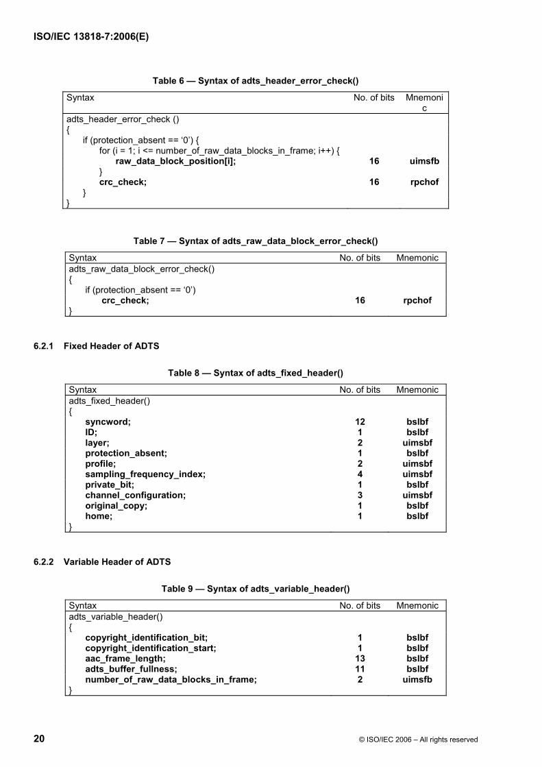
Table 6 — Syntax of adts_header_error_check()
Syntax No. of bits Mnemonic
adts_header_error_check () { if (protection_absent == ‘0’) { for (i = 1; i <= number_of_raw_data_blocks_in_frame; i++) { raw_data_block_position[i]; 16 uimsfb } crc_check; 16 rpchof } }
Table 7 — Syntax of adts_raw_data_block_error_check()
Syntax No. of bits Mnemonic adts_raw_data_block_error_check() { if (protection_absent == ‘0’) crc_check; 16 rpchof }
6.2.1 Fixed Header of ADTS
Table 8 — Syntax of adts_fixed_header()
Syntax No. of bits Mnemonic adts_fixed_header() { syncword; 12 bslbf ID; 1 bslbf layer; 2 uimsbf protection_absent; 1 bslbf profile; 2 uimsbf sampling_frequency_index; 4 uimsbf private_bit; 1 bslbf channel_configuration; 3 uimsbf original_copy; 1 bslbf home; 1 bslbf }
6.2.2 Variable Header of ADTS
Table 9 — Syntax of adts_variable_header()
Syntax No. of bits Mnemonic adts_variable_header() { copyright_identification_bit; 1 bslbf copyright_identification_start; 1 bslbf aac_frame_length; 13 bslbf adts_buffer_fullness; 11 bslbf number_of_raw_data_blocks_in_frame; 2 uimsfb }

ISO/IEC 13818-7:2006(E)
© ISO/IEC 2006 – All rights reserved 21
6.2.3 Error Detection
Table 10 — Syntax of adts_error_check()
Syntax No. of bits Mnemonic adts_error_check() { if (protection_absent == ‘0’) crc_check; 16 rpchof }
6.3 Raw Data
Table 11 — Syntax of raw_data_stream()
Syntax No. of bits Mnemonic raw_data_stream() { while ( data_available() ) { raw_data_block(); } }
Table 12 — Syntax of raw_data_block()
Syntax No. of bits Mnemonic raw_data_block() { while ((id = id_syn_ele) != ID_END) { 3 uimsbf switch (id) { case ID_SCE: single_channel_element(); break; case ID_CPE: channel_pair_element(); break; case ID_CCE: coupling_channel_element(); break; case ID_LFE: lfe_channel_element(); break; case ID_DSE: data_stream_element(); break; case ID_PCE: program_config_element(); break; case ID_FIL: fill_element(); } } byte_alignment(); }
ISO/IEC 13818-7:2006(E)
22 © ISO/IEC 2006 – All rights reserved
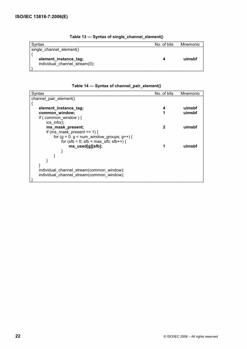
Table 13 — Syntax of single_channel_element()
Syntax No. of bits Mnemonic single_channel_element() { element_instance_tag; 4 uimsbf individual_channel_stream(0); }
Table 14 — Syntax of channel_pair_element()
Syntax No. of bits Mnemonic channel_pair_element() { element_instance_tag; 4 uimsbf common_window; 1 uimsbf if ( common_window ) { ics_info(); ms_mask_present; 2 uimsbf if (ms_mask_present == 1) { for (g = 0; g < num_window_groups; g++) { for (sfb = 0; sfb < max_sfb; sfb++) { ms_used[g][sfb]; 1 uimsbf } } } } individual_channel_stream(common_window); individual_channel_stream(common_window); }

ISO/IEC 13818-7:2006(E)
© ISO/IEC 2006 – All rights reserved 23
Table 15 — Syntax of ics_info()
Syntax No. of bits Mnemonic ics_info() { ics_reserved_bit; 1 bslbf window_sequence; 2 uimsbf window_shape; 1 uimsbf if (window_sequence == EIGHT_SHORT_SEQUENCE) { max_sfb; 4 uimsbf scale_factor_grouping; 7 uimsbf } else { max_sfb; 6 uimsbf predictor_data_present; 1 uimsbf if (predictor_data_present) { predictor_reset; 1 uimsbf if (predictor_reset) { predictor_reset_group_number; 5 uimsbf } for (sfb = 0; sfb < min(max_sfb, PRED_SFB_MAX); sfb++) {
prediction_used[sfb]; 1 uimsbf } } } }
Table 16 — Syntax of individual_channel_stream()
Syntax No. of bits Mnemonic individual_channel_stream(common_window) { global_gain; 8 uimsbf if (!common_window) ics_info(); section_data(); scale_factor_data(); pulse_data_present; 1 uismbf if (pulse_data_present) { pulse_data(); } tns_data_present; 1 uimsbf if (tns_data_present) { tns_data(); } gain_control_data_present; 1 uimsbf if (gain_control_data_present) { gain_control_data(); } spectral_data(); }

ISO/IEC 13818-7:2006(E)
24 © ISO/IEC 2006 – All rights reserved
Table 17 — Syntax of section_data()
Syntax No. of bits Mnemonic section_data() { if (window_sequence == EIGHT_SHORT_SEQUENCE) sect_esc_val = (1<<3) - 1; else sect_esc_val = (1<<5) - 1; for (g = 0; g < num_window_groups; g++) { k = 0; i = 0; while (k < max_sfb) { sect_cb[g][i]; 4 uimsbf sect_len = 0; while (sect_len_incr == sect_esc_val) { {3;5} uimsbf sect_len += sect_esc_val; } sect_len += sect_len_incr; sect_start[g][i] = k; sect_end[g][i] = k+sect_len; for (sfb = k; sfb < k+sect_len; sfb++) sfb_cb[g][sfb] = sect_cb[g][i]; k += sect_len; i++; } num_sec[g] = i; } }
Table 18 — Syntax of scale_factor_data()
Syntax No. of bits Mnemonic
scale_factor_data() { for (g = 0; g < num_window_groups; g++) { for (sfb = 0; sfb < max_sfb; sfb++) { if (sfb_cb[g][sfb] != ZERO_HCB) { if (is_intensity(g,sfb)) hcod_sf[dpcm_is_position[g][sfb]]; 1..19 vlclbf else hcod_sf[dpcm_sf[g][sfb]]; 1..19 vlclbf } } } }

ISO/IEC 13818-7:2006(E)
© ISO/IEC 2006 – All rights reserved 25
Table 19 — Syntax of tns_data()
Syntax No. of bits Mnemonic tns_data() { for (w = 0; w < num_windows; w++) { n_filt[w]; 1..2 uimsbf if (n_filt[w]) coef_res[w]; 1 uimsbf for (filt = 0; filt < n_filt[w]; filt++) { length[w][filt]; {4;6} uimsbf order[w][filt]; {3;5} uimsbf if (order[w][filt]) { direction[w][filt]; 1 uimsbf coef_compress[w][filt]; 1 uimsbf for (i = 0; i < order[w][filt]; i++) coef[w][filt][i]; 2..4 uimsbf } } } }
Table 20 — Syntax of spectral_data()
Syntax No. of bits Mnemonic spectral_data() { for (g = 0; g < num_window_groups; g++) { for (i = 0; i < num_sec[g]; i++) { if (sect_cb[g][i] != ZERO_HCB && sect_cb[g][i] <= ESC_HCB) {
for (k = sect_sfb_offset[g][sect_start[g][i]]; k < sect_sfb_offset[g][sect_end[g][i]]; ) { if (sect_cb[g][i]<FIRST_PAIR_HCB) { hcod[sect_cb[g][i]][w][x][y][z]; 1..16 vlclbf if (unsigned_cb[sect_cb[g][i]]) quad_sign_bits; 0..4 bslbf k += QUAD_LEN; } else { hcod[sect_cb[g][i]][y][z]; 1..15 vlclbf if (unsigned_cb[sect_cb[g][i]]) pair_sign_bits; 0..2 bslbf k += PAIR_LEN; if (sect_cb[g][i] == ESC_HCB) { if (y == ESC_FLAG) hcod_esc_y; 5..21 vlclbf if (z == ESC_FLAG) hcod_esc_z; 5..21 vlclbf } } } } } } }

ISO/IEC 13818-7:2006(E)
26 © ISO/IEC 2006 – All rights reserved
Table 21 — Syntax of pulse_data()
Syntax No. of bits Mnemonic pulse_data() { number_pulse; 2 uimsbf pulse_start_sfb; 6 uimsbf for (i = 0; i < number_pulse+1; i++) { pulse_offset[i]; 5 uimsbf pulse_amp[i]; 4 uimsbf } }
Table 22 — Syntax of coupling_channel_element()
Syntax No. of bits Mnemonic coupling_channel_element() { element_instance_tag; 4 uimsbf ind_sw_cce_flag; 1 uimsbf num_coupled_elements; 3 uimsbf num_gain_element_lists = 0; for (c = 0; c < num_coupled_elements+1; c++) { num_gain_element_lists++; cc_target_is_cpe[c]; 1 uimsbf cc_target_tag_select[c]; 4 uimsbf if (cc_target_is_cpe[c]) { cc_l[c]; 1 uimsbf cc_r[c]; 1 uimsbf if (cc_l[c] && cc_r[c]) num_gain_element_lists++; } } cc_domain; 1 uimsbf gain_element_sign; 1 uimsbf gain_element_scale; 2 uimsbf individual_channel_stream(0); for (c = 1; c < num_gain_element_lists; c++) { if (ind_sw_cce_flag) { cge = 1; } else { common_gain_element_present[c]; 1 uimsbf cge = common_gain_element_present[c]; } if (cge) hcod_sf[common_gain_element[c]]; 1..19 vlclbf else { for (g = 0; g < num_window_groups; g++) { for (sfb = 0; sfb < max_sfb; sfb++) { if (sfb_cb[g][sfb] != ZERO_HCB); hcod_sf[dpcm_gain_element[c][g][sfb]]; 1..19 vlclbf } } } } }

ISO/IEC 13818-7:2006(E)
© ISO/IEC 2006 – All rights reserved 27
Table 23 — Syntax of lfe_channel_element()
Syntax No. of bits Mnemonic lfe_channel_element() { element_instance_tag; 4 uimsbf individual_channel_stream(0); }
Table 24 — Syntax of data_stream_element()
Syntax No. of bits Mnemonic data_stream_element() { element_instance_tag; 4 uimsbf data_byte_align_flag; 1 uimsbf cnt = count; 8 uimsbf if (cnt == 255) { cnt += esc_count; 8 uimsbf } if (data_byte_align_flag) { byte_alignment(); } for (i = 0; i < cnt; i++) { data_stream_byte[element_instance_tag][i]; 8 uimsbf } }

ISO/IEC 13818-7:2006(E)
28 © ISO/IEC 2006 – All rights reserved
Table 25 — Syntax of program_config_element()
Syntax No. of bits Mnemonic program_config_element() { element_instance_tag; 4 uimsbf profile; 2 uimsbf sampling_frequency_index; 4 uimsbf num_front_channel_elements; 4 uimsbf num_side_channel_elements; 4 uimsbf num_back_channel_elements; 4 uimsbf num_lfe_channel_elements; 2 uimsbf num_assoc_data_elements; 3 uimsbf num_valid_cc_elements; 4 uimsbf mono_mixdown_present; 1 uimsbf if (mono_mixdown_present == 1) mono_mixdown_element_number; 4 uimsbf stereo_mixdown_present; 1 uimsbf if (stereo_mixdown_present == 1) stereo_mixdown_element_number; 4 uimsbf matrix_mixdown_idx_present; 1 uimsbf if (matrix_mixdown_idx_present == 1) { matrix_mixdown_idx ; 2 uimsbf pseudo_surround_enable; 1 uimsbf } for (i = 0; i < num_front_channel_elements; i++) { front_element_is_cpe[i]; 1 bslbf front_element_tag_select[i]; 4 uimsbf } for (i = 0; i < num_side_channel_elements; i++) { side_element_is_cpe[i]; 1 bslbf side_element_tag_select[i]; 4 uimsbf } for (i = 0; i < num_back_channel_elements; i++) { back_element_is_cpe[i]; 1 bslbf back_element_tag_select[i]; 4 uimsbf } for (i = 0; i < num_lfe_channel_elements; i++) lfe_element_tag_select[i]; 4 uimsbf for (i = 0; i < num_assoc_data_elements; i++) assoc_data_element_tag_select[i]; 4 uimsbf for (i = 0; i < num_valid_cc_elements; i++) { cc_element_is_ind_sw[i]; 1 uimsbf valid_cc_element_tag_select[i]; 4 uimsbf } byte_alignment(); comment_field_bytes; 8 uimsbf for (i = 0; i < comment_field_bytes; i++) comment_field_data[i]; 8 uimsbf }

ISO/IEC 13818-7:2006(E)
© ISO/IEC 2006 – All rights reserved 29
Table 26 — Syntax of fill_element()
Syntax No. of bits Mnemonic fill_element() { cnt = count; 4 uimsbf if (cnt == 15) cnt += esc_count - 1; 8 uimsbf while (cnt > 0) { cnt -= extension_payload(cnt); } }
ISO/IEC 13818-7:2006(E)
30 © ISO/IEC 2006 – All rights reserved
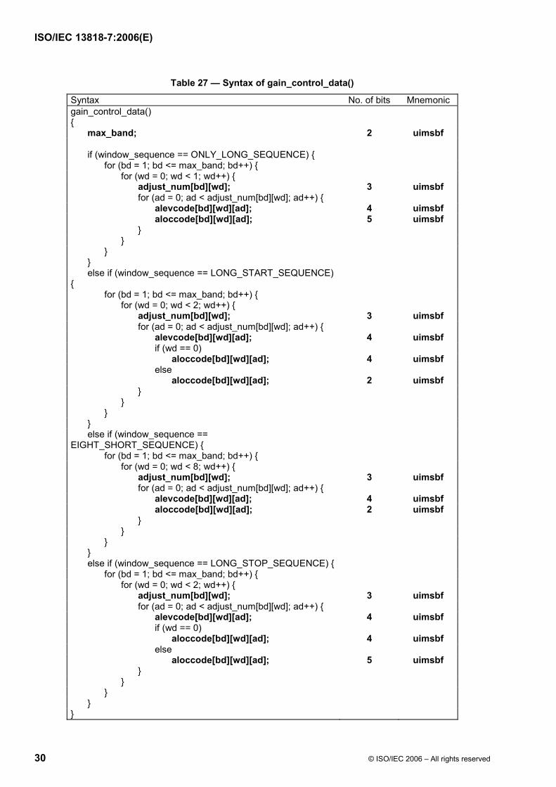
Table 27 — Syntax of gain_control_data()
Syntax No. of bits Mnemonic gain_control_data() { max_band; 2 uimsbf if (window_sequence == ONLY_LONG_SEQUENCE) {
for (bd = 1; bd <= max_band; bd++) { for (wd = 0; wd < 1; wd++) { adjust_num[bd][wd]; 3 uimsbf for (ad = 0; ad < adjust_num[bd][wd]; ad++) { alevcode[bd][wd][ad]; 4 uimsbf aloccode[bd][wd][ad]; 5 uimsbf } } } } else if (window_sequence == LONG_START_SEQUENCE) {
for (bd = 1; bd <= max_band; bd++) { for (wd = 0; wd < 2; wd++) { adjust_num[bd][wd]; 3 uimsbf for (ad = 0; ad < adjust_num[bd][wd]; ad++) { alevcode[bd][wd][ad]; 4 uimsbf if (wd == 0) aloccode[bd][wd][ad]; 4 uimsbf else aloccode[bd][wd][ad]; 2 uimsbf } } } } else if (window_sequence == EIGHT_SHORT_SEQUENCE) {
for (bd = 1; bd <= max_band; bd++) { for (wd = 0; wd < 8; wd++) { adjust_num[bd][wd]; 3 uimsbf for (ad = 0; ad < adjust_num[bd][wd]; ad++) { alevcode[bd][wd][ad]; 4 uimsbf aloccode[bd][wd][ad]; 2 uimsbf } } } } else if (window_sequence == LONG_STOP_SEQUENCE) { for (bd = 1; bd <= max_band; bd++) { for (wd = 0; wd < 2; wd++) { adjust_num[bd][wd]; 3 uimsbf for (ad = 0; ad < adjust_num[bd][wd]; ad++) { alevcode[bd][wd][ad]; 4 uimsbf if (wd == 0) aloccode[bd][wd][ad]; 4 uimsbf else aloccode[bd][wd][ad]; 5 uimsbf } } } } }

ISO/IEC 13818-7:2006(E)
© ISO/IEC 2006 – All rights reserved 31
Table 28 — Syntax of extension_payload()
extension_payload(cnt) { extension_type; 4 uimsbf switch (extension_type) { case EXT_DYNAMIC_RANGE: n = dynamic_range_info(); return n; case EXT_SBR_DATA: return sbr_extension_data(id_aac, 0); Note 1 case EXT_SBR_DATA_CRC: return sbr_extension_data(id_aac, 1); Note 1 case EXT_FILL_DATA: fill_nibble; /* must be ‘0000’ */ 4 uimsbf for (i = 0; i < cnt-1; i++) fill_byte[i]; /* must be ‘10100101’ */ 8 uimsbf return cnt; case default: for (i = 0; i < 8*(cnt-1)+4; i++) other_bits[i]; 1 uimsbf return cnt; } } Note 1: id_aac is the id_syn_ele of the corresponding AAC element (ID_SCE or ID_CPE) or ID_SCE in case of CCE.

ISO/IEC 13818-7:2006(E)
32 © ISO/IEC 2006 – All rights reserved
Table 29 — Syntax of dynamic_range_info()
Syntax No. of bits Mnemonic dynamic_range_info() { n = 1; drc_num_bands = 1; pce_tag_present; 1 uimsbf if (pce_tag_present == 1) { pce_ instance_tag; 4 uimsbf drc_tag_reserved_bits; 4 n++; } excluded_chns_present; 1 uimsbf if (excluded_chns_present == 1) { n += excluded_channels(); } drc_bands_present ; 1 uimsbf if (drc_bands_present == 1) { drc_band_incr; 4 uimsbf drc_bands_reserved_bits; 4 uimsbf n++; drc_num_bands = drc_num_bands + drc_band_incr; for (i = 0; i < drc_num_bands; i++) { drc_band_top[i]; 8 uimsbf n++; } } prog_ref_level_present; 1 uimsbf if (prog_ref_level_present == 1) { prog_ref_level; 7 uimsbf prog_ref_level_reserved_bits; 1 uimsbf n++; } for (i = 0; i < drc_num_bands; i++) { dyn_rng_sgn[i]; 1 uimsbf dyn_rng_ctl[i]; 7 uimsbf n++; } return n; }

ISO/IEC 13818-7:2006(E)
© ISO/IEC 2006 – All rights reserved 33
Table 30 — Syntax of excluded_channels()
Syntax No. Of bits Mnemonic excluded_channels( ) { n = 0; num_excl_chan = 70; for (i = 0; i < 7; i++) exclude_mask[i]; 1 uimsbf n++; while (additional_excluded_chns[n-1] == 1) { 1 uimsbf for (i = num_excl_chan; i < num_excl_chan+7; i++) exclude_mask[i]; 1 uimsbf n++; num_excl_chan += 7; } return n; }
7 Profiles and Profile Interoperability
7.1 Profiles
There are three profiles identified in the MPEG-2 AAC standard:
Main Profile
Low Complexity Profile
Scalable Sampling Rate Profile
In the program_config_element() and adts_fixed_header(), a two bit field indicates the profile in use:
Table 31 — Profiles
index profile 0 Main profile 1 Low Complexity profile (LC) 2 Scalable Sampling Rate profile (SSR) 3 (reserved)
7.1.1 Main
The Main profile is used when memory cost is not significant, and when there is substantial processing power available. With the exception of the gain control tool, all parts of the tools may be used in order to provide the best data compression possible. There shall be only one program (in the sense of what is specified in a program_config_element()) in a Main profile bitstream. The program in a Main profile bitstream shall not contain any mono or stereo mixdown elements.
7.1.2 Low Complexity
The Low Complexity profile is used when RAM usage, processing power, and compression requirements are all present. In the low complexity profile, prediction, and gain control tool are not permitted and TNS order is limited. There shall be only one program (in the sense of what is specified in a program_config_element()) in a Low Complexity profile bitstream. The program in a Low Complexity profile bitstream shall not contain any mono or stereo mixdown elements.

ISO/IEC 13818-7:2006(E)
34 © ISO/IEC 2006 – All rights reserved
7.1.3 Scalable Sampling Rate
In the Scalable Sampling Rate profile, the gain-control tool is required. Prediction and coupling channels are not permitted, and TNS order and bandwidth are limited. Gain control is not used in the lowest of the 4 PQF subbands. In the case of a reduced audio bandwidth, the SSR profile will scale accordingly in complexity. There shall be only one program (in the sense of what is specified in a program_config_element()) in a Scalable Sampling Rate profile bitstream. The program in a Scalable Sampling Rate profile bitstream shall not contain any mono or stereo mixdown elements.
7.1.4 Naming Convention for MPEG-2 AAC Decoders and Bitstreams
A decoder or bitstream may be specified as an A.L.I.D Channel <Profile Name> Profile MPEG-2 AAC decoder or bitstream, where A is replaced by the number of main audio channels, L by the number of LFE channels, I by the number of independently switched coupling channels, D by the number of dependently switched coupling channels, and Profile Name by the actual profile name. An example would be a 5.1.1.1 Channel Main Profile MPEG-2 AAC Decoder, indicating a decoder capable of decoding 5 main audio channels, one LFE channel, and one each independently and dependently switched CCE, with each of the channels using the profile specified. This can be abbreviated as M.5.1.1.1 where the "M" indicates a main profile decoder. Similarly, a Low Complexity decoder can be specified by a leading "L", and an SSR profile by an "S".
7.1.4.1 Naming Convention for MPEG-2 AAC + MPEG-4 SBR Decoders and Bitstreams
A decoder or bitstream conforming additionally to the MPEG-4 AOT SBR at a certain level may be referenced in a similar manner by appending "+ SBR / X [HQ/LP]" to the name, where X is replaced with the level of the HE-AAC profile decoder/bitstream with the same characteristics as specified by ISO/IEC 14496-3. An example would be a 5.1.1.1 Channel Main Profile MPEG-2 AAC + SBR / 5 HQ Decoder.
7.1.5 Minimum Decoder Capability for Specified Number of Main Audio Channels and Profile
To insure a certain level of interoperability the following minimum decoder capabilities for decoders of a given profile and number of main audio channels are specified.
Table 32 — Profile dependent minimum decoder capabilities in terms of channel configuration
Number of Main Audio Channels
Main Profile Capability
Low Complexity
Profile Capability
SSR Profile
Capability
1 1.0.0.0 1.0.0.0 1.0.0.0 2 2.0.0.0 2.0.0.0 2.0.0.0 3 3.0.1.0 3.0.0.1 3.0.0.0 4 4.0.1.0 4.0.0.1 4.0.0.0 5 5.1.1.1 5.1.0.1 5.1.0.0 7 7.1.1.2 7.1.0.2 7.1.0.0
7.1.6 Profile Dependent Tool Parameters
Maximum TNS order and bandwidth:
According to the profile in use, the value for the constant TNS_MAX_ORDER is set as follows for long windows: For the main profile the constant TNS_MAX_ORDER is 20, for the low complexity profile and the scalable sampling rate profile the constant TNS_MAX_ORDER is 12. For short windows, the constant TNS_MAX_ORDER is 7 for all profiles.

ISO/IEC 13818-7:2006(E)
© ISO/IEC 2006 – All rights reserved 35
According to the sampling rate and profile in use, the value for the constant TNS_MAX_BANDS is set as follows:
Table 33 — Profile and sampling rate dependent definition of TNS_MAX_BANDS
Sampling Rate [Hz]
Low Complexity / Main Profile
(long windows)
Low Complexity / Main Profile
(short windows)
Scalable Sampling Rate
Profile (long windows)
Scalable Sampling Rate Profile
(short windows)
96000 31 9 28 7 88200 31 9 28 7 64000 34 10 27 7 48000 40 14 26 6 44100 42 14 26 6 32000 51 14 26 6 24000 46 14 29 7 22050 46 14 29 7 16000 42 14 23 8 12000 42 14 23 8 11025 42 14 23 8 8000 39 14 19 7
7.2 Profile Interoperability
7.2.1 Interoperability of Bitstreams and Decoders
Any bitstream of a given profile (see Table 34) whose number of main audio channels, LFE channels, independent coupling channels, and dependent coupling channels is less than or equal to the corresponding number of channels supported by a decoder of the same profile can be decoded by that decoder.
Table 34 describes the interoperability of the three profiles.
Table 34 — Profile Interoperability
Encoder Profile
Decoder Profile Main Profile LC Profile SSR Profile
Main Profile yes yes no *
LC Profile no yes no *
SSR Profile no no ** yes
*In Table 34, these entries can be decoded if the main or LC profile decoder is able to parse, but not decode, the gain control information, but the reconstructed audio will have a limited bandwidth.
**In Table 33, this entry can be decoded, but the bandwidth of the decoded signal will be limited to approximately 5 kHz, corresponding to the nonaliased portion of the first PQMF filter band.

ISO/IEC 13818-7:2006(E)
36 © ISO/IEC 2006 – All rights reserved
Scalable Sampling Rate
20 kHz
18 kHz
12 kHz
6 kHz
Main
Low Complexity
Figure 3 — Profile Interoperability
8 Overall Data Structure
8.1 AAC Interchange Formats
8.1.1 Overview
The raw_data_block() contains all data which belongs to the audio (including ancillary data). Beyond that, additional information like sampling_frequency is needed to fully describe an audio sequence. The Audio Data Interchange Format (ADIF) contains all elements that are necessary to describe a bitstream according to this standard.
For specific applications some or all of the syntax elements like those specified in the header of the ADIF, e.g. sampling_rate, may be known to the decoder by other means and hence do not appear in the bitstream.
Furthermore, additional information that varies from block to block (e.g. to enhance the parsability or error resilience) may be required. Therefore transport streams may be designed for a specific application and are not specified in this standard. However, one non-normative transport stream, called Audio Data Transport Stream (ADTS), is described. It may be used for applications in which the decoder can parse this stream.
8.1.2 Audio Data Interchange Format (ADIF)
8.1.2.1 Overview
The Audio Data Interchange Format (ADIF) contains one header at the start of the sequence followed by a raw_data_stream(). The raw_data_stream() may not contain any further program_config_element()’s.
As such, the ADIF is useful only for systems with a defined start and no need to start decoding from within the audio data stream, such as decoding from disk file. It can be used as an interchange format in that it contains all information necessary to decode and play the audio data.

ISO/IEC 13818-7:2006(E)
© ISO/IEC 2006 – All rights reserved 37
8.1.2.2 Definitions
8.1.2.2.1 Data Functions
adif_sequence() a sequence according to the Audio Data Interchange Format (Table 2).
adif_header() header of the Audio Data Interchange Format located at the beginning of an adif_sequence (Table 3).
byte_alignment() Align with respect to the first bit of the header.
raw_data_stream() see subclause 8.2.1 and Table 11.
program_config_element() contains information about the configuration for one program (Table 3). See subclause 8.5.
8.1.2.2.2 Data Elements
adif_id ID that indicates the Audio Data Interchange Format. Its value is 0x41444946 (most significant bit first), the ASCII representation of the string „ADIF“ (Table 3).
copyright_id_present indicates whether copyright_id is present or not (Table 3).
copyright_id The field consists of an 8-bit copyright_identifier, followed by a 64-bit copyright_number (Table 3). The copyright identifier is given by a Registration Authority as designated by SC 29. The copyright_number is a value which identifies uniquely the copyrighted material. See ISO/IEC 13818-3, definition of data element copyright_identification_bit.
original_copy see ISO/IEC 11172-3, definition of data element copyright.
home see ISO/IEC 11172-3, definition of data element original/copy.
bitstream_type a flag indicating the type of a bitstream (Table 3):
‘0’ constant rate bitstream. This bitstream may betransmitted via a channel with constant rate
‘1’ variable rate bitstream. This bitstream is not designed fortransmission via constant rate channels
bitrate a 23 bit unsigned integer indicating either the bitrate of the bitstream in bits/sec in case of constant rate bitstream or the maximum peak bitrate (measured per frame) in case of variable rate bitstreams. A value of 0 indicates that the bitrate is not known (Table 3).
num_program_config_element number of program_config_element()´s specified for this adif_sequence() is equal to num_program_config_element+1 (Table 3). The minimum value is 0 indicating 1 program_config_element().
adif_buffer_fullness state of the bit reservoir after encoding the first raw_data_block() in the adif_sequence(). It is transmitted as the number of available bits in the bit reservoir (Table 3).

ISO/IEC 13818-7:2006(E)
38 © ISO/IEC 2006 – All rights reserved
8.1.2.2.3 Help Elements
data_available() Function that returns ‘1’ as long as data is available, otherwise ‘0’.
8.1.3 Audio Data Transport Stream (ADTS)
8.1.3.1 Overview
The Audio Data Transport Stream (ADTS) is similar to syntax used in ISO/IEC 11172-3 and ISO/IEC 13818-3. This will be recognized by ISO/IEC 11172-3 and ISO/IEC 13818-3 decoders as a “Layer 4” bitstream.
The fixed header of the ADTS contains the syncword plus all parts of the header which are necessary for decoding and which do not change from frame to frame. The variable header of the ADTS contains header data which changes from frame to frame.
8.1.3.2 Definitions
8.1.3.2.1 Data Functions
adts_sequence() a sequence according to Audio Data Transport Stream ADTS (Table 4).
adts_frame() an ADTS frame, consisting of a fixed header, a variable header, an optional error check and a specified number of raw_data_block()'s (Table 5).
adts_fixed_header() fixed header of ADTS. The information in this header does not change from frame to frame. It is repeated every frame to allow random access into a bitstream bitstream (Table 8).
adts_variable_header() variable header of ADTS. This header is transmitted every frame as well as the fixed header, but contains data that changes from frame to frame (Table 9).
adts_error_check() The following bits are protected and fed into the CRC algorithm in order of their appearance:
• all bits of adts_fixed_header()
• all bits of adts_variable_header()
• first 192 bits of any
o single_channel_element()
o channel_pair_element()
o coupling_channel_element()
o lfe_channel_element()
• First 128 bits of the second individual_channel_stream() in the channel_pair_element() must be protected.
• All information in any program_config_element() or data_stream_element() must be protected.
For any element where the specified protection length of 128 or 192 bits exceeds its actual length, the element is zero padded to the specified protection length for CRC calculation.

ISO/IEC 13818-7:2006(E)
© ISO/IEC 2006 – All rights reserved 39
The id_syn_ele bits shall be excluded from CRC protection. If the length of a CPE is shorter than 192 bits, zero data are appended to achieve the length of 192 bits. Furthermore, if the first ICS of the CPE ends at the Nth bit (N<192), the first (192 – N) bits of the second ICS are protected twice, each time in order of their appearance. For example, if the second ICS starts at the 190th bit of CPE, the first 3 bits of the second ICS are protected twice. Finally, if the length of the second ICS is shorter than 128 bits, zero data are appended to achieve the length of 128 bits.
adts_header_error_check() The following bits are protected and fed into the CRC algorithm in order of their appearance:
• all bits of adts_fixed_header()
• all bits of adts_variable_header()
• all bits of every raw_data_block_position[i].
adts_raw_data_block_error_check() With regard to the i-th adts_raw_data_block_error_check(), the bits of the i-th raw_data_block() are protected and fed into the CRC algorithm in order of their appearance according to what is specified with regard to the adts_error_check() with the exception that no header bits are considered.
raw_data_block() see subclause 8.2.1 and Table 12.
8.1.3.2.2 Data Elements
raw_data_block_position[i] Start position of the i-th raw_data_block() in the adts_frame(), measured as an offset in bytes from the start position of the first raw_data_block() in the adts_frame().
crc_check CRC error detection data generated as described in ISO/IEC 11172-3, subclause 2.4.3.1 (Table 6, Table 7 and Table 10).
syncword The bit string ‘1111 1111 1111’. See ISO/IEC 11172-3, subclause 2.4.2.3 (Table 8).
ID MPEG identifier, set to ‘1’. See ISO/IEC 11172-3, subclause 2.4.2.3 (Table 8).
layer Indicates which layer is used. Set to ‘00’. See ISO/IEC 11172-3, subclause 2.4.2.3 (Table 8).
protection_absent Indicates whether error_check() data is present or not. Same as syntax element ‘protection_bit’ in ISO/IEC 11172-3, subclause 2.4.1 and 2.4.2 (Table 8).
profile profile used. See clause 2 (Table 8).
sampling_frequency_index indicates the sampling frequency used according to the following table (Table 8):

ISO/IEC 13818-7:2006(E)
40 © ISO/IEC 2006 – All rights reserved
Table 35 — Sampling frequency dependent on sampling_frequency_index
sampling_frequency_index sampling frequeny [Hz] 0x0 96000 0x1 88200 0x2 64000 0x3 48000 0x4 44100 0x5 32000 0x6 24000 0x7 22050 0x8 16000 0x9 12000 0xa 11025 0xb 8000 0xc reserved 0xd reserved 0xe reserved 0xf reserved
private_bit see ISO/IEC 11172-3, subclause 2.4.2.3 (Table 8).
channel_configuration indicates the channel configuration used. If channel_configuration is greater than 0, the channel configuration is given in Table 42, see subclause 8.5.3.1. If channel_configuration equals 0, the channel configuration is not specified in the header and must be given by a program_config_element() following as first syntactic element in the first raw_data_block() after the header (see subclause 8.5.3.2), or by the implicit configuration (see subclause 8.5.3.3) or must be known in the application (Table 8).
original_copy see definition in 8.1.2.2.2.
home see definition in 8.1.2.2.2.
copyright_identification_bit One bit of the 72-bit copyright identification field (see copyright_id above). The bits of this field are transmitted frame by frame; the first bit is indicated by the copyright_identification_start bit set to ‘1’. The field consists of an 8-bit copyright_identifier, followed by a 64-bit copyright_number. The copyright identifier is given by a Registration Authority as designated by SC29. The copyright_number is a value which identifies uniquely the copyrighted material. See ISO/IEC 13818-3, subclause 2.5.2.13 (Table 9).
copyright_identification_start One bit to indicate that the copyright_identification_bit in this audio frame is the first bit of the 72-bit copyright identification. If no copyright identification is transmitted, this bit should be kept '0'.'0' no start of copyright identification in this audio frame '1' start of copyright identification in this audio frame See ISO/IEC 13818-3, subclause 2.5.2.13 (Table 9).
aac_frame_length Length of the frame including headers and error_check in bytes (Table 9).
adts_buffer_fullness state of the bit reservoir in the course of encoding the ADTS frame, up to and including the first raw_data_block() and the

ISO/IEC 13818-7:2006(E)
© ISO/IEC 2006 – All rights reserved 41
optionally following adts_raw_data_block_error_check(). It is transmitted as the number of available bits in the bit reservoir divided by NCC divided by 32 and truncated to an integer value (Table 9). A value of hexadecimal 7FF signals that the bitstream is a variable rate bitstream. In this case, buffer fullness is not applicable.
number_of_raw_data_blocks_in_frame Number of raw_data_block()’s that are multiplexed in the adts_frame() is equal to number_of_raw_data_blocks_in_frame + 1. The minimum value is 0 indicating 1 raw_data_block() (Table 9).
8.2 Raw Data
8.2.1 Definitions
8.2.1.1 Data Functions
raw_data_stream() sequence of raw_data_block()’s.
raw_data_block() block of raw data that contains audio data for a time period of 1024 samples, related information and other data. There are seven syntactic elements, identified by the data element id_syn_ele. The audio_channel_element()'s in one raw_data_stream() and one raw_data_block() must have one and only one sampling rate. In the raw_data_block(), several instances of the same syntactic element may occur, but must have a different 4 bit element_instance_tag, except for data_stream_element()'s and fill_element()'s. Therefore, in one raw_data_block(), there can be from 0 to at most 16 instances of any syntactic element, except for data_stream_element()'s and fill_element()'s, where this limitation does not apply. If multiple data_stream_element()'s occur which have the same element_instance_tag then they are part of the same data stream. The fill_element() has no element_instance_tag (since the content does not require subsequent reference) and can occur any number of times. The end of a raw_data_block() is indicated with a special id_syn_ele (TERM), which may occur only once in a raw_data_block(). (Table 12).
single_channel_element() abbreviaton SCE. Syntactic element of the bitstream containing coded data for a single audio channel. A single_channel_element() basically consists of an individual_channel_stream(). There may be up to 16 such elements per raw data block, each one must have a unique element_instance_tag (Table 13).
channel_pair_element() abbreviation CPE. Syntactic element of the bitstream containing data for a pair of channels. A channel_pair_element() consists of two individual_channel_stream()’s and additional joint channel coding information. The two channels may share common side information. The channel_pair_element() has the same restrictions as the single channel element as far as element_instance_tag, and number of occurrances (Table 14).
coupling_channel_element() Abbreviation CCE. Syntactic element that contains audio data for a coupling channel. A coupling channel represents the information for multi-channel intensity for one block, or alternately for dialogue for multilingual programming. The rules for number

ISO/IEC 13818-7:2006(E)
42 © ISO/IEC 2006 – All rights reserved
of coupling_channel_element()'s and instance tags are as for single_channel_element()'s (Table 22). See subclause 12.3.
lfe_channel_element() Abbreviation LFE. Syntactic element that contains a low sampling frequency enhancement channel. The rules for the number of lfe_channel_element()'s and instance tags are as for single_channel_element()'s (Table 23). See subclause 8.4.
audio_channel_element() generic term for single_channel_element(), channel_pair_element(), coupling_channel_element() and lfe_channel_element().
program_config_element() Abbreviation PCE. Syntactic element that contains program configuration data. The rules for the number of program_config_element()’s and element_instance_tag’s are the same as for single_channel_element()’s (Table 25). PCE’s must come before all other syntactic elements in a raw_data_block(). See subclause 8.5.
fill_element() Abbreviation FIL. Syntactic element that contains fill data. There may be any number of fill elements, that can come in any order in the raw data block (Table 26). See subclause 8.7.
data_stream_element() Abbreviation DSE. Syntactic element that contains data. Again, there are 16 element_instance_tags. There is, however, no restriction on the number of data_stream_element()'s with any one instance tag, as a single data stream may continue across multiple data_stream_element()'s with the same instance tag (Table 24). See subclause 8.5.3.
byte_alignment() Align with respect to the first bit of the raw_data_block().
8.2.2 Data Elements
id_syn_ele a data element that identifies either a syntactic element or the end of a raw_data_block() (Table 12):
Table 36 — Syntaxtic element identification
ID name encoding Abbreviation Syntactic Element ID_SCE 0x0 SCE single_channel_element()ID_CPE 0x1 CPE channel_pair_element() ID_CCE 0x2 CCE coupling_channel_element()ID_LFE 0x3 LFE lfe_channel_element() ID_DSE 0x4 DSE data_stream_element() ID_PCE 0x5 PCE program_config_element()ID_FIL 0x6 FIL fill_element()
ID_END 0x7 TERM
element_instance_tag Unique instance tag for syntactic elements other than fill_element(). All syntactic elements containing instance tags may occur more than once, but, except for data_stream_element()'s, must have a unique element_instance_tag in each raw_data_block(). This tag is also used to reference audio syntactic elements in single_channel_element()'s, channel_pair_element()'s, lfe_channel_element()'s, data_channel_element()'s, and coupling_channel_element()'s inside a program_config_element(), and provides the possibility of up to 16 independent program_config_element()’s (Table 13, Table 14, Table 22, Table 23, Table 24, Table 25, Table 26).

ISO/IEC 13818-7:2006(E)
© ISO/IEC 2006 – All rights reserved 43
8.2.3 Buffer Requirements
8.2.3.1 Minimum Decoder Input Buffer
The following rules are used to calculate the maximum number of bits in the input buffer both for the bitstream as a whole, for any given program, or for any given SCE/CPE/CCE:
The input buffer size is 6144 bits per SCE or independently switched CCE, plus 12288 bits per CPE (6144*NCC). Both the total buffer and the individual buffer sizes are limited, so that the buffering limit can be calculated for either the entire bitstream, any entire program, or the individual audio_channel_element()'s permitting the decoder to break a multichannel bitstream into separate mono and stereo bitstreams which are decoded by separate mono and stereo decoders, respectively. All bits for LFE’s or dependent CCE's must be supplied from the total buffer requirements based on the independent CCE's, SCE's, and CPE's. Furthermore, all bits required for any DSE’s, PCE’s, FIL’s, or fixed headers, variable headers, byte_alignment, and CRC must also be supplied from the same total buffer requirements.
8.2.3.2 Bit Reservoir
The bit reservoir is controlled at the encoder. The maximum bit reservoir in the encoder depends on the NCC and the mean bitrate. The maximum bit reservoir size for constant rate channels can be calculated by subtracting the mean number of bits per block from the minimum decoder input buffer size. For example, at 96 kbit/s for a stereo signal at 44.1 kHz sampling frequency the mean number of bits per block (mean_framelength) is ( 96000 bit/s / 44100 1/s * 1024 ) = 2229.1156… . This leads to a maximum bit reservoir size (max_bit_reservoir) of INT ( 12288 bit - 2229.1156… ) = 10058. For variable bitrate channels the encoder must operate in a way that the input buffer requirements do not exceed the minimum decoder input buffer.
The state of the bit reservoir (bit_reservoir_state) is transmitted in the buffer_fullness field, either as the state of the bit reservoir truncated to an integer value (adif_buffer_fullness) or as the state of the bit reservoir divided by NCC divided by 32 and truncated to an integer value (adts_buffer_fullness).
The bit_reservoir_state of subsequent frames can be derived as follows:
[ ] [ ] [ ]framehframelengthframelengtmeanframestatereservoirbitframestateoirbit_reserv −+−= _1___
Framelengths have to be adjusted such that the following restriction is met
[ ] reservoirmax_bitframestateoirbit_reserv __0 ≤≤
8.2.3.3 Maximum Bitrate
Maximum bitrate:
The maximum bitrate depends on the audio sampling rate. It can be calculated based on the minimum input buffer size according to the formula:
NCCfrequencysampling
blocksamples
blockbit
⋅⋅ _1024
6144
Table 37 gives some examples of the maximum bitrates per channel depending on the used sampling frequency.

ISO/IEC 13818-7:2006(E)
44 © ISO/IEC 2006 – All rights reserved
Table 37 — Maximum bitrate depending on the sampling frequency
sampling_frequency maximum bitrate / NCC 48 kHz 288 kbit/s
44.1 kHz 264.6 kbit/s 32 kHz 192 kbit/s
8.2.4 Decoding Process
Assuming that the start of a raw_data_block() is known, it can be decoded without any additional „transport-level“ information and produces 1024 audio samples per output channel. The sampling rate of the audio signal, as specified by the sampling_frequency_index, may be specified in a program_config_element() or it may be implied in the specific application domain. In the latter case, the sampling_frequency_index must be deduced in order for the bitstream to be parsed.
Since a given sampling frequency is associated with only one sampling frequency table, and since maximum flexibility is desired in the range of possible sampling frequencies, the following Table shall be used to associate an implied sampling frequency with the desired sampling frequency dependent tables.
Table 38 — Sampling frequency mapping
Frequency range (in Hz)
Use tables for sampling frequency (in Hz)
f >= 92017 96000 92017 > f >= 75132 88200 75132 > f >= 55426 64000 55426 > f >= 46009 48000 46009 > f >= 37566 44100 37566 > f >= 27713 32000 27713 > f >= 23004 24000 23004 > f >= 18783 22050 18783 > f >= 13856 16000 13856 > f >= 11502 12000 11502 > f >= 9391 11025
9391 > f 8000
The raw_data_stream supports encoding for both constant rate and variable rate channels. In each case the structure of the bitstream and the operation of the decoder are identical except for some minor qualifications. For constant rate channels, the encoder may have to insert a FIL element to adjust the rate upwards to exactly the desired rate. A decoder reading from a constant rate channel must accumulate a minimum number of bits in its input buffer prior to the start of decoding so that output buffer underrun does not occur. In the case of variable rate, demand read channels, each raw_data_block() can have the minimum length (rate) such that the desired audio quality is achieved, and in the decoder there is no minimum input data requirement prior to the start of decoding.
Examples of the simplest possible bitstreams are:
bitstream segment output signal <SCE><TERM><SCE><TERM>… mono signal <CPE><TERM><CPE><TERM>… stereo signal <SCE><CPE><CPE><LFE><TERM><SCE><CPE><CPE><LFE><TERM>… 5.1 channel signal
where angle brackets (< >) are used to delimit syntactic elements. For the mono signal each SCE must have the same value in its element_instance_tag, and similarly, for the stereo signal each CPE must have the same value in its element_instance_tag. For the 5.1 channel signal each SCE must have the same value in

ISO/IEC 13818-7:2006(E)
© ISO/IEC 2006 – All rights reserved 45
its element_instance_tag, each CPE associated with the front channel pair must have the same value in its element_instance_tag, and each CPE associated with the back channel pair must have the same value in its element_instance_tag.
If these bitstreams are to be transmitted over a constant rate channel then they might include a fill_element() to adjust the instantaneous bitrate. In this case an example of a coded stereo signal is
<CPE><FIL><TERM><CPE><FIL><TERM>…
If the bitstreams are to carry ancillary data and run over a constant rate channel then an example of a coded stereo signal is
<CPE><DSE><FIL><TERM><CPE><DSE><FIL><TERM>…
All data_stream_element()'s have the same element_instance_tag if they are part of the same data stream.
8.3 Single Channel Element (SCE), Channel Pair Element (CPE) and Individual Channel Stream (ICS)
8.3.1 Definitions
8.3.1.1 Data Elements
common_window a flag indicating whether the two individual_channel_stream()’s share a common ics_info() or not. In case of sharing, the ics_info() is part of the channel_pair_element() and must be used for both channels. Otherwise, the ics_info() is part of each individual_channel_stream() (Table 14).
ics_reserved_bit flag reserved for future use. Shall be '0'.
window_sequence indicates the sequence of windows as defined in Table 44 (Table 15).
window_shape A 1 bit field that determines what window is used for the trailing part of this analysis window (Table 15).
max_sfb number of scalefactor bands transmitted per group (Table 15).
scale_factor_grouping A bit field that contains information about grouping of short spectral data (Table 15).
8.3.1.2 Data Functions
individual_channel_stream() contains data necessary to decode one channel (Table 16).
ics_info() contains side information necessary to decode an individual_channel_stream(). The individual_channel_stream()’s of a channel_pair_element() may share one common ics_info() (Table 15).
8.3.1.3 Help Elements scalefactor window band term for scalefactor bands within a window, given in Table 45 to
Table 57.
scalefactor band term for scalefactor band within a group. In the case of EIGHT_SHORT_SEQUENCE and grouping a scalefactor band

ISO/IEC 13818-7:2006(E)
46 © ISO/IEC 2006 – All rights reserved
may contain several scalefactor window bands of corresponding frequency. For all other window_sequences scalefactor bands and scalefactor window bands are identical.
g group index.
win window index within group.
sfb scalefactor band index within group.
swb scalefactor window band index within window.
bin coefficient index.
num_window_groups number of groups of windows which share one set of scalefactors.
window_group_length[g] number of windows in each group.
bit_set(bit_field,bit_num) function that returns the value of bit number bit_num of a bit_field (most right bit is bit 0).
num_windows number of windows of the actual window sequence.
num_swb_long_window number of scalefactor bands for long windows. This number has to be selected depending on the sampling frequency. See subclause 8.9.
num_swb_short_window number of scalefactor window bands for short windows. This number has to be selected depending on the sampling frequency. See subclause 8.9.
num_swb number of scalefactor window bands for shortwindows in case of EIGHT_SHORT_SEQUENCE, number of scalefactor window bands for long windows otherwise.
swb_offset_long_window[swb] Table containing the index of the lowest spectral coefficient of scalefactor band sfb for long windows. This Table has to be selected depending on the sampling frequency. See subclause 8.9.
swb_offset_short_window[swb] Table containing the index of the lowest spectral coefficient of scalefactor band sfb for short windows. This Table has to be selected depending on the sampling frequency. See subclause 8.9.
swb_offset[swb] Table containing the index of the lowest spectral coefficient of scalefactor band sfb for short windows in case of EIGHT_SHORT_SEQUENCE, otherwise for long windows.
sect_sfb_offset[g][section] Table that gives the number of the start coefficient for the section_data() within a group. This offset depends on the window_sequence and scale_factor_grouping.
sampling_frequency_index see subclause 8.1.2.1.

ISO/IEC 13818-7:2006(E)
© ISO/IEC 2006 – All rights reserved 47
8.3.2 Decoding Process
8.3.2.1 Decoding a single_channel_element() and channel_pair_element()
A single_channel_element() is composed of an element_instance_tag and an individual_channel_stream. In this case ics_info() is always located in the individual_channel_stream.
A channel_pair_element() begins with an element_instance_tag and common_window flag. If the common_window equals ‘1’, then ics_info() is shared amongst the two individual_channel_stream elements and the MS information is transmitted. If common_window equals ‘0’, then there is an ics_info() within each individual_channel_stream and there is no MS information.
8.3.2.2 Decoding an individual_channel_stream()
In the individual_channel_stream, the order of decoding is:
get global_gain
get ics_info() (parse bitstream if common information is not present)
get section_data()
get scalefactor_data(), if present
get pulse_data(), if present
get tns_data(), if present
get gain_control_data(), if present
get spectral_data(), if present.
The process of recovering pulse_data is described in clause 9, tns_data in clause 14, and gain_control data in clause 16. An overview of how to decode ics_info() (subclause 8.3), section data (clause 9), scalefactor data (clause 9 and 11), and spectral data (clause 9) will be given here.
8.3.2.3 Recovering ics_info()
For single_channel_element()’s ics_info() is always located immediately after the global_gain in the inidividual_channel_stream(). For a channel_pair_element() there are two possible locations for the ics_info(). If each individual channel in the pair window switch together then the ics_info() is located immediately after common_window in the channel_pair_element() and common_window is set to 1. Otherwise there is an ics_info() immediately after global_gain in each of the two individual_channel_stream() in the channel_pair_element() and common_window is set to 0.
ics_info() carries window information associated with an ICS and thus permits channels in a channel_pair to switch separately if desired. In addition it carries the max_sfb which places an upper limit on the number of ms_used[] and predictor_used[] bits that must be transmitted. If the window_sequence is EIGHT_SHORT_SEQUENCE then scale_factor_grouping is transmitted. If a set of short windows form a group then they share scalefactors as well as intensity stereo positions and have their spectral coefficients interleaved. The first short window is always a new group so no grouping bit is transmitted. Subsequent short windows are in the same group if the associated grouping bit is 1. A new group is started if the associated grouping bit is 0. It is assumed that grouped short windows have similar signal statistics. Hence their spectra are interleaved so as to place correlated coefficients next to each other. The manner of interleaving is indicated in Figure 6. ics_info() also carries the prediction data for the individual channel or channel pair (see clause 13).

ISO/IEC 13818-7:2006(E)
48 © ISO/IEC 2006 – All rights reserved
8.3.2.4 Recovering Sectioning Data
In the ICS, the information about one long window, or eight short windows, is recovered. The sectioning data is the first field to be decoded, and describes the Huffman codes that apply to the scalefactor bands in the ICS (see clause 9 and 11). The form of the section data is:
sect_cb The codebook for the section
and
sect_len The length of the section.
This length is recovered by reading the bitstream sequentially for a section length, adding the escape value to the total length of the section until a non-escape value is found, which is added to establish the total length of the section. This process is clearly explained in the C-like syntax description. Note that within each group the sections must delineate the scalefactor bands from zero to max_sfb so that the first section within each group starts at bands zero and the last section within each group ends at max_sfb.
The sectioning data describes the codebook, and then the length of the section using that codebook, starting from the first scalefactor band and continuing until the total number of scalefactor bands is reached.
After this description is provided, all scalefactors and spectral data corresponding to codebook zero are zeroed, and no values corresponding to these scalefactors or spectral data will be transmitted. When scanning for scale-factor data it is important to note that scalefactors for any scalefactor bands whose Huffman codebook is zero will be omitted. Similarly, all spectral data associated with Huffman codebook zero are omitted (see clause 9 and 11).
In addition spectral data associated with the scalefactor bands that have an intensity codebook will not be transmitted, but intensity steering coefficients will be transmitted in place of the scalefactors, as described in subclause 12.2.
8.3.2.5 Scalefactor Data Parsing and Decoding
For each scalefactor band that is not in a section coded with the zero codebook (ZERO_HCB), a scalefactor is transmitted. These will be denoted as ‘active’ scalefactor bands and the associated scalefactors as active scalefactors. Global gain, the first data element in an ICS, is typically the value of the first active scalefactor. All scalefactors (and steering coefficients) are transmitted using Huffman coded DPCM relative to the previous active scalefactor (see clause 9 and 11). The first active scalefactor is differentially coded relative to the global gain. Note that it is not illegal, merely inefficient, to provide a global_gain that is different from the first active scalefactor and then a non-zero DPCM value for the first scalefactor DPCM value. If any intensity steering coefficients are received interspersed with the DPCM scalefactor elements, they are sent to the intensity stereo module, and are not involved in the DPCM coding of scalefactor values (see subclause 12.2). The value of the first active scalefactor is usually transmitted as the global_gain with the first DPCM scalefactor having a zero value. Once the scalefactors are decoded to their integer values, the actual values are found via a power function (see clause 11).
8.3.2.6 Spectral Data Parsing and Decoding
The spectral data is recovered as the last part of the parsing of an ICS. It consists of all the non-zeroed coefficients remaining in the spectrum or spectra, ordered as described in the ICS_info. For each non-zero, non-intensity codebook, the data are recovered via Huffman decoding in quads or pairs, as indicated in the noiseless coding tool (see clause 9). If the spectral data is associated with an unsigned Huffman codebook, the necessary sign bits follow the Huffman codeword (see subclause 9.3). In the case of the ESCAPE codebook, if any escape value is received, a corresponding escape sequence will appear after that Huffman code. There may be zero, one or two escape sequences for each codeword in the ESCAPE codebook, as indicated by the presence of escape values in that decoded codeword. For each section the Huffman decoding continues until all the spectral values in that section have been decoded. Once all sections have been decoded, the data is multiplied by the decoded scalefactors and deinterleaved if necessary.

ISO/IEC 13818-7:2006(E)
© ISO/IEC 2006 – All rights reserved 49
8.3.3 Windows and Window Sequences
Quantization and coding is done in the frequency domain. For this purpose, the time signal is mapped into the frequency domain in the encoder. The decoder performs the inverse mapping as described in clause 15. Depending on the signal, the coder may change the time/frequency resolution by using two different windows: LONG_WINDOW and SHORT_WINDOW. To switch between windows, the transition windows LONG_START_WINDOW and LONG_STOP_WINDOW are used. Table 43 lists the windows, specifies the corresponding transform length and shows the shape of the windows schematically. Two transform lengths are used: 1024 (referred to as long transform) and 128 coefficients (refered to as short transform).
Window sequences are composed of windows in a way that a raw_data_block() always contains data representing 1024 output samples. The data element window_sequence indicates the window sequence that is actually used. Table 44 lists how the window sequences are composed of individual windows. Refer to clause 15 for more detailed information about the transform and the windows.
8.3.4 Scalefactor Bands and Grouping
Many tools of the decoder perform operations on groups of consecutive spectral values called scalefactor bands (abbreviation ‘sfb’). The width of the scalefactor bands is built in imitation of the critical bands of the human auditory system. For that reason the number of scalefactor bands in a spectrum and their width depend on the transform length and the sampling frequency. Table 45 to Table 57 list the offset to the beginning of each scalefactor band for the transform lengths 1024 and 128 and the different sampling frequencies, respectively.
To reduce the amount of side information in case of sequences which contain SHORT_WINDOWS, consecutive SHORT_WINDOWs may be grouped (see Figure 4). The information about the grouping is contained in the scale_factor_grouping data element. Grouping means that only one set of scalefactors is transmitted for all grouped windows as if there was only one window. The scalefactors are then applied to the corresponding spectral data in all grouped windows. To increase the efficiency of the noiseless coding (see clause 9), the spectral data of a group is transmitted in an interleaved order given in subclause 8.3.5. The interleaving is done on a scalefactor band by scalefactor band basis, so that the spectral data can be grouped to form a virtual scalefactor band to which the common scalefactor can be applied. Within this document the expression ‘scalefactor band’ (abbreviation ‘sfb’) denotes these virtual scalefactor bands. If the scalefactor bands of the single windows are referred to, the expression ‘scalefactor window band’ (abbreviation ‘swb’) is used. Due to its influence on the scalefactor bands, grouping affects the meaning of section_data (see clause 9), the order of spectral data (see subclause 8.3.5), and the total number of scalefactor bands. For a LONG_WINDOW scalefactor bands and scalefactor window bands are identical since there is only one group with only one window.
To reduce the amount of information needed for the transmission of side information specific to each scalefactor band, the data element max_sfb is transmitted. Its value is one greater than the highest active scalefactor band in all groups. max_sfb has influence on the interpretation of section data (see clause 9), the transmission of scalefactors (see clause 9 and 11), the transmission of predictor data (see clause 13) and the transmission of the ms_mask (see subclause 12.1).
Since scalefactor bands are a basic element of the coding algorithm, some help variables and arrays are needed to describe the decoding process in all tools using scalefactor bands. These help variables depend on sampling_frequency, window_sequence, scalefactor_grouping and max_sfb and must be built up for each raw_data_block(). The pseudo code shown below describes
• how to determine the number of windows in a window_sequence num_windows
• how to determine the number of window_groups num_window_groups
• how to determine the number of windows in each group window_group_length[g]
• how to determine the total number of scalefactor window bands num_swb for the actual window type
• how to determine swb_offset[swb], the offset of the first coefficient in scalefactor window band swb of the window actually used

ISO/IEC 13818-7:2006(E)
50 © ISO/IEC 2006 – All rights reserved
• how to determine sect_sfb_offset[g][section], the offset of the first coefficient in section section. This offset depends on window_sequence and scale_factor_grouping and is needed to decode the spectral_data().
A long transform window is always described as a window_group containing a single window. Since the number of scalefactor bands and their width depend on the sampling frequency, the affected variables are indexed with sampling_frequency_index to select the appropriate table.
fs_index = sampling_frequency_index; switch (window_sequence) { case ONLY_LONG_SEQUENCE: case LONG_START_SEQUENCE: case LONG_STOP_SEQUENCE: num_windows = 1; num_window_groups = 1; window_group_length[num_window_groups-1] = 1; num_swb = num_swb_long_window[fs_index]; /* preparation of sect_sfb_offset for long blocks */ /* also copy the last value! */ for (i = 0; i < max_sfb + 1; i++) { sect_sfb_offset[0][i] = swb_offset_long_window[fs_index][i]; swb_offset[i] = swb_offset_long_window[fs_index][i]; } break; case EIGHT_SHORT_SEQUENCE: num_windows = 8; num_window_groups = 1; window_group_length[num_window_groups-1] = 1; num_swb = num_swb_short_window[fs_index]; for (i = 0; i < num_swb_short_window[fs_index] + 1; i++) swb_offset[i] = swb_offset_short_window[fs_index][i]; for (i = 0; i < num_windows-1; i++) { if(bit_set(scale_factor_grouping,6-i)) == 0) { num_window_groups += 1; window_group_length[num_window_groups-1] = 1; } else { window_group_length[num_window_groups-1] += 1; } } /* preparation of sect_sfb_offset for short blocks */ for (g = 0; g < num_window_groups; g++) { sect_sfb = 0; offset = 0; for (i = 0; i < max_sfb; i++) { width = swb_offset_short_window[fs_index][i+1] - swb_offset_short_window[fs_index][i]; width *= window_group_length[g]; sect_sfb_offset[g][sect_sfb++] = offset; offset += width; } sect_sfb_offset[g][sect_sfb] = offset; } break; default: break; }
8.3.5 Order of Spectral Coefficients in spectral_data()
For ONLY_LONG_SEQUENCE windows (num_window_groups = 1, window_group_length[0] = 1) the spectral data is in ascending spectral order, as shown in Figure 5.

ISO/IEC 13818-7:2006(E)
© ISO/IEC 2006 – All rights reserved 51
For the EIGHT_SHORT_SEQUENCE window, the spectral order depends on the grouping in the following manner:
• Groups are ordered sequentially
• Within a group, a scalefactor band consists of the spectral data of all grouped SHORT_WINDOWs for the associated scalefactor window band. To clarify via example, the length of a group is in the range of one to eight SHORT_WINDOWs.
• If there are eight groups each with length one (num_window_groups = 8, window_group_length[0] = 1), the result is a sequence of eight spectrums, each in ascending spectral order.
• If there is only one group with length eight (num_window_group = 1, window_group_length[0] = 8), the results is that spectral data of all eight SHORT_WINDOWs is interleaved by scalefactor window bands.
• Figure 6 shows the spectral ordering for an EIGHT_SHORT_SEQUENCE with grouping of SHORT_WINDOWs according to Figure 4 (num_window_groups = 4).
• Within a scalefactor window band, the coefficients are in ascending spectral order.
8.3.6 Output Word Length
The global gain for each audio channel is scaled such that the integer part of the output of the IMDCT can be used directly as a 16-bit PCM audio output to a digital-to-analog (D/A) converter. This is the default mode of operation and will result in correct audio levels. If the decoder has a D/A converter that has greater than 16-bit resolution then the output of the IMDCT can be scaled up such that the appropriate number of fractional bits are included to form the desired D/A word size. In this case the level of the converter output would be matched to that of a 16-bit D/A, but would have the advantage of greater signal dynamic range and lower converter noise floor. Similarly, shorter D/A word lengths can be accommodated.
8.4 Low Frequency Enhancement Channel (LFE)
8.4.1 General
In order to maintain a regular structure of the decoder, the lfe_channel_element() is defined as a standard individual_channel_stream(0) element, i.e. equal to a single_channel_element(). Thus, decoding can be done using the standard procedure for decoding a single_channel_element().
In order to accomodate a more bitrate and hardware efficient implementation of the LFE decoder, however, several restrictions apply to the options used for the encoding of this element:
• The window_shape field is always set to 0, i.e. sine window (see subclause 6.3, Table 15).
• The window_sequence field is always set to 0 (ONLY_LONG_SEQUENCE) (see subclause 6.3, Table 15).
• Only the lowest 12 spectral coefficients of any LFE may be non-zero.
• No Temporal Noise Shaping is used, i.e. tns_data_present is set to 0 (see subclause 6.3, Table 16).
• No prediction is used, i.e. predictor_data_present is set to 0 (see subclause 6.3, Table 15).
The presence of LFE channels depends on the profile used. Refer to clause 7 for detailed information.
8.5 Program Config Element (PCE)
A program_config_element() may occur outside the AAC payload e. g. in the adif_header(), but also inside the AAC payload as syntactic element in a raw_data_block().

ISO/IEC 13818-7:2006(E)
52 © ISO/IEC 2006 – All rights reserved
8.5.1 Data Functions
byte_alignment() For PCEs within a raw_data_block(), align with respect to the first bit of the raw_data_block(). For PCEs within the adif_header(), align with respect to the first bit of the header.
8.5.2 Data Elements
profile The two-bit profile index from Table 31 (Table 25).
sampling_frequency_index Indicates the sampling rate of the program (and all other programs in this bitstream). See definition in subclause 8.1.2.1 (Table 25).
num_front_channel_elements The number of audio syntactic elements in the front channels, front center to back center, symmetrically by left and right, or alternating by left and right in the case of single channel elements (Table 25).
num_side_channel_elements Number of elements to the side as above (Table 25).
num_back_channel_elements As number of side and front channel elements, for back channels (Table 25).
num_lfe_channel_elements Number of LFE channel elements associated with this program (Table 25).
num_assoc_data_elements The number of associated data elements for this program (Table 25).
num_valid_cc_elements The number of CCE's that can add to the audio data for this program (Table 25).
mono_mixdown_present One bit, indicating the presence of the mono mixdown element (Table 25).
mono_mixdown_element_number The number of a specified SCE that is the mono mixdown (Table 25).
stereo_mixdown_present One bit, indicating that there is a stereo mixdown present (Table 25).
stereo_mixdown_element_number The number of a specified CPE that is the stereo mixdown element (Table 25).
matrix_mixdown_idx_present One bit indicating the presence of matrix mixdown information by means of a stereo matrix coefficient index (see Table 39). For all configurations other than the 3/2 format this bit must be zero (Table 25).
matrix_mixdown_idx Two bit field, specifying the index of the mixdown coefficient to be used in the 5-channel to 2-channel matrix-mixdown. Possible matrix coefficients are listed in Table 39 (Table 25).
pseudo_surround_enable One bit, indicating the possibility of mixdown for pseudo surround reproduction (Table 25).
front_element_is_cpe indicates whether a SCE or a CPE is addressed as a front element (Table 25).‘0’ selects an SCE.‘1’ selects an CPE. The
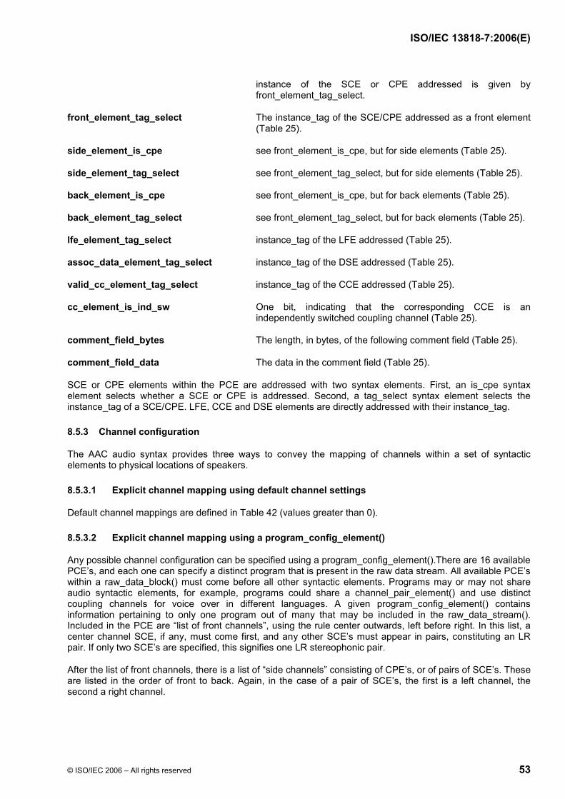
ISO/IEC 13818-7:2006(E)
© ISO/IEC 2006 – All rights reserved 53
instance of the SCE or CPE addressed is given by front_element_tag_select.
front_element_tag_select The instance_tag of the SCE/CPE addressed as a front element (Table 25).
side_element_is_cpe see front_element_is_cpe, but for side elements (Table 25).
side_element_tag_select see front_element_tag_select, but for side elements (Table 25).
back_element_is_cpe see front_element_is_cpe, but for back elements (Table 25).
back_element_tag_select see front_element_tag_select, but for back elements (Table 25).
lfe_element_tag_select instance_tag of the LFE addressed (Table 25).
assoc_data_element_tag_select instance_tag of the DSE addressed (Table 25).
valid_cc_element_tag_select instance_tag of the CCE addressed (Table 25).
cc_element_is_ind_sw One bit, indicating that the corresponding CCE is an independently switched coupling channel (Table 25).
comment_field_bytes The length, in bytes, of the following comment field (Table 25).
comment_field_data The data in the comment field (Table 25).
SCE or CPE elements within the PCE are addressed with two syntax elements. First, an is_cpe syntax element selects whether a SCE or CPE is addressed. Second, a tag_select syntax element selects the instance_tag of a SCE/CPE. LFE, CCE and DSE elements are directly addressed with their instance_tag.
8.5.3 Channel configuration
The AAC audio syntax provides three ways to convey the mapping of channels within a set of syntactic elements to physical locations of speakers.
8.5.3.1 Explicit channel mapping using default channel settings
Default channel mappings are defined in Table 42 (values greater than 0).
8.5.3.2 Explicit channel mapping using a program_config_element()
Any possible channel configuration can be specified using a program_config_element().There are 16 available PCE’s, and each one can specify a distinct program that is present in the raw data stream. All available PCE’s within a raw_data_block() must come before all other syntactic elements. Programs may or may not share audio syntactic elements, for example, programs could share a channel_pair_element() and use distinct coupling channels for voice over in different languages. A given program_config_element() contains information pertaining to only one program out of many that may be included in the raw_data_stream(). Included in the PCE are “list of front channels”, using the rule center outwards, left before right. In this list, a center channel SCE, if any, must come first, and any other SCE’s must appear in pairs, constituting an LR pair. If only two SCE’s are specified, this signifies one LR stereophonic pair.
After the list of front channels, there is a list of “side channels” consisting of CPE’s, or of pairs of SCE’s. These are listed in the order of front to back. Again, in the case of a pair of SCE’s, the first is a left channel, the second a right channel.

ISO/IEC 13818-7:2006(E)
54 © ISO/IEC 2006 – All rights reserved
After the list of side channels, a list of back channels is available, listed from outside in. Any SCE’s except the last SCE must be paired, and the presence of exactly two SCE’s (alone or preceeded by a CPE) indicates that the two SCE’s are Left and Right Rear center, respectively.
The configuration indicated by the PCE takes effect at the raw_data_block() containing the PCE. The number of front, side and back channels as specified in the PCE must be present in that block and all subsequent raw_data_block()'s until a raw_data_block() containing a new PCE is transmitted.
Other elements are also specified. A list of one or more LFE’s is specified for application to this program. A list of one or more CCE’s (profile-dependent) is also provided, in order to allow for dialog management as well as different intensity coupling streams for different channels using the same main channels. A list of data streams associated with the program can also associate one or more data streams with a program. The program configuration element also allows for the specification of one monophonic and one stereophonic simulcast mixdown channel for a program. Note that the MPEG-2 Systems standard ISO/IEC 13818-1 supports alternate methods of simulcast.
A PCE element is not intended to allow for rapid program changes. At any time when a given PCE, as selected by its element_instance_tag, defines a new (as opposed to repeated) program, the decoder is not obliged to provide audio signal continuity.
8.5.3.3 Implicit channel mapping
If no explicit channel mapping is given, the following methods describe the implicit channel mapping:
1) Any number of SCE's may appear (as long as permitted by other constraints, for example profile). If this number of SCE's is odd, then the first SCE represents the front center channel, and the other SCE's represent L/R pairs of channels, proceeding from center front outwards and back to center rear.
If the number of SCE's is even, then the SCE's are assigned as pairs as center-front L/R, in pairs proceeding out and back from center front toward center back.
2) Any number of CPE's or pairs of SCE's may appear. Each CPE or pair of SCE's represents one L/R pair, proceeding from where the first sets of SCE's left off, pairwise until reaching either center back pair.
3) Any number of SCEs may appear. If this number is even, allocating pairs of SCEs Left/Right, from 2), back to center back. If this number is odd, allocated as L/R pairs, except for the final SCE, which is assigned to center back..
4) Any number of LFEs may appear. No speaker mapping is defined in case of multiple LFEs.
In the case of such implicit channel mapping the number and order of SCEs, CPEs and LFEs and the resulting configuration may not change within the bitstream without sending a program_config_element(), i.e. an implicit reconfiguration is not allowed.
Other audio syntactic elements that do not imply additional output speakers, such as coupling channel_element, may follow the listed set of syntactic elements. Obviously non-audio syntactic elements may be received in addition and in any order relative to the listed syntactic elements.
8.5.4 Matrix-mixdown Method
8.5.4.1 Description
The matrix-mixdown method applies only for mixing a 3-front/2-back speaker configuration, 5-channel program, down to a stereo or a mono program. It is not applicable to any program with other than the 3/2 configuration.

ISO/IEC 13818-7:2006(E)
© ISO/IEC 2006 – All rights reserved 55
8.5.4.2 Matrix-mixdown Process
A derived stereo signal can be generated within a matrix-mixdown decoder by use of one of the two following sets of equations.
Set 1:
]2[211
1'
]2[211
1'
S
S
RACRA
R
LACLA
L
⋅++⋅++
=
⋅++⋅++
=
Set 2:
)](2[2211
1'
)](2[2211
1'
SS
SS
RLACRA
R
RLACLA
L
+⋅++⋅⋅++
=
+⋅−+⋅⋅++
=
Where L, C, R, LS and RS are the source signals, L’ and R’ are the derived stereo signals and A is the matrix coefficient indicated by matrix_mixdown_idx. LFE channels are omitted from the mixdown.
If pseudo_surround_enable is not set, then only set 1 should be used. If pseudo_surround_enable is set, then either set 1 or set 2 equations can be used, depending on whether the receiver has facilities to invoke some form of surround synthesis.
As further information it should be noted that one can derive a mono signal using the following equation:
[ ])(231
SS RLARCLA
M +⋅+++⋅⋅+
=
8.5.4.3 Advisory
The matrix-mixdown provision enables a mode of operation which may be beneficial to some operators in some circumstances. However, it is advised that this method should not be used. The psychoacoustic principles on which the audio coding are based are violated by this form of post-processing, and a perceptually faithful reconstruction of the signal cannot be guaranteed. The preferred method is to use the stereo or mono mixdown channels in the AAC syntax to provide stereo or mono programming which is specifically created by conventional studio mixing prior to bitrate reduction.
The stereo and mono mixdown channels additionally enable the content provider to separately optimize the stereo and multichannel program mixes - this is not possible by using the matrix-mixdown method.
It is additionally relevant to note that, due to the algorithms used for the multichannel and stereo mixdown coding, a better combination of quality and bitrate is usually provided by use of the stereo mixdown channels than can be provided by the matrix-mixdown process.

ISO/IEC 13818-7:2006(E)
56 © ISO/IEC 2006 – All rights reserved
8.5.4.4 Tables
Table 39 — Matrix-mixdown coefficients
matrix_mixdown_idx A 0 21
1 21
2 )22(1 3 0
8.6 Data Stream Element (DSE)
8.6.1 Data Functions
byte_alignment() align with respect to the first bit of the raw_data_block().
8.6.2 Data Elements
data_byte_align_flag One bit indicating that a byte aligment is performed within the data stream element (Table 24)
count Initial value for length of data stream (Table 24)
esc_count Incremental value of length of data or padding element (Table 24)
data_stream_byte A data stream byte extracted from bitstream (Table 24)
A data element contains any additional data, e.g. auxiliary information, that is not part of the audio information itself. Any number of data elements with the same element_instance_tag or up to 16 data elements with different element_instance_tags are possible. The decoding process of the data element is described in this clause.
8.6.3 Decoding Process
The first syntactic element to be read is the 1 bit data_byte_align_flag. Next is the 8 bit value count. It contains the initial byte-length of the data stream. If count equals 255, its value is incremented by a second 8 bit value, esc_count, this final value represents the number of bytes in the data stream element. If data_byte_align_flag is set, a byte alignment is performed. The bytes of the data stream follow.
8.7 Fill Element (FIL)
8.7.1 Data Elements
count Initial value for length of extension_payload() (Table 26).
esc_count Incremental value for length of extension_payload() (Table 26).
8.7.2 Decoding Process
fill_element()’s might be added to allow for several kinds of extension payloads. Any number of fill_element()’s is allowed.
The syntactic element count gives the initial value of the length of the fill data. In the same way as for the data element this value is incremented with the value of esc_count if count equals 15. The resulting number gives the number of fill_bytes to be read.

ISO/IEC 13818-7:2006(E)
© ISO/IEC 2006 – All rights reserved 57
8.8 Extension Payload
8.8.1 General
8.8.1.1 Data Elements
extension_type Four bit field indicating the type of fill element content (Table 26).
8.8.1.2 Decoding Process
Any number of extension_payload()’s are allowed.
The following symbolic abbreviations for values of the extension_type field are defined:
Table 40 — Values of the extension_type data element
Symbol Value of extension_type
Purpose
EXT_FILL ‘0000’ Bitstream filler EXT_FILL_DATA ‘0001’ Bitstream data as filler
EXT_DYNAMIC_RANGE ‘1011’ Dynamic range control EXT_SBR_DATA ‘1101’ SBR enhancement
EXT_SBR_DATA_CRC ‘1110’ SBR enhancement with CRC - all other values reserved
The ‘reserved’ values might be used for further extension of the syntax in a compatible way.
8.8.2 Fill data and other bits
8.8.2.1 Data Elements
fill_nibble Four bit field for fill (Table 28).
fill_byte Byte to be discarded by the decoder (Table 28).
other_bits Bits to be discarded by the decoder (Table 28).
8.8.2.2 Decoding Process
Fill data shall be added if the total bits for all audio data together with all additional data is lower than the minimum allowed number of bits in this frame necessary to reach the target bitrate. Under normal conditions fill bits are avoided and free bits are used to fill up the bit reservoir. Fill bits are written only if the bit reservoir is full.
Note that fill_nibble is normatively defined to be ‘0000’ and fill_byte is normatively defined to be ‘10100101’ (to ensure that self-clocked data streams, such as radio modems, can perform reliable clock recovery).
8.8.3 Dynamic Range Control (DRC)
8.8.3.1 Data Elements
pce_tag_present One bit indicating that program element tag is present (Table 29).
pce_instance_tag Tag field that indicates with which program the dynamic range information is associated (Table 29)

ISO/IEC 13818-7:2006(E)
58 © ISO/IEC 2006 – All rights reserved
drc_tag_reserved_bits Reserved (Table 29)
excluded_chns_present One bit indicating that excluded channels are present (Table 29)
drc_bands_present One bit indicating that DRC multi-band information is present (Table 29)
drc_band_incr Number of DRC bands greater than 1 having DRC information (Table 29)
drc_bands_reserved_bits Reserved (Table 29)
drc_band_top[i] Indicates top of i-th DRC band in units of 4 spectral lines (Table 29).If drc_band_top[i] = k, then the index (w.r.t zero) of the highest spectral coefficient that is in the i-th DRC band is = k*4+3. In case of an EIGHT_SHORT_SEQUENCE window_sequence the index is interpreted as pointing into the concatenated array of 8*128 (de-interleaved) frequency points corresponding to the 8 short transforms.
prog_ref_level_present One bit indicating that reference level is present (Table 29).
prog_ref_level Reference level. A measure of long-term program audio level for all channels combined (Table 29).
prog_ref_level_reserved_bits Reserved (Table 29)
dyn_rng_sgn[i] Dynamic range control sign information. One bit indicating the sign of dyn_rng_ctl (0 if positive, 1 if negative, (Table 29)
dyn_rng_ctl[i] Dynamic range control magnitude information (Table 29)
exclude_mask[i] Boolean array indicating the audio channels of a program that are excluded from DRC processing using this DRC information.
additional_excluded_chns[i] One bit indicating that additional excluded channels are present (Table 30)
8.8.3.2 Decoding Process
The evaluation of potentially available dynamic range control information in the decoder is optional.
prog_ref_level_present indicates that prog_ref_level is being transmitted. This permits prog_ref_level to be sent as infrequently as desired (e.g. once), although periodic transmission would permit break-in.
prog_ref_level is quantized in 0.25 dB steps using 7 bits, and therefore has a range of approximately 32 dB. It indicates program level relative to full scale (i.e. dB below full scale), and is reconstructed as:
24/__232767 levelrefproglevel −⋅=
where „full scale level„ is 32767 (prog_ref_level equal to 0).
pce_tag_present indicates that pce_instance_tag is being transmitted. This permits pce_instance_tag to be sent as infrequently as desired (e.g. once), although periodic transmission would permit break-in.
pce_instance_tag indicates with which program the dynamic range information is associated. If this is not present then the default program is indicated. Since each AAC bitstream typically has just one program, this would be the most common mode. Each program in a multi-program bitstream would send its dynamic range

ISO/IEC 13818-7:2006(E)
© ISO/IEC 2006 – All rights reserved 59
information in a distinct extension_payload() of the fill_element(). In the multiple program case, the pce_instance_tag would always have to be signaled.
The drc_tag_reserved_bits fill out the optional fields to an integral number of bytes in length.
The excluded_chns_present bit indicates that channels that are to be excluded from dynamic range processing will be signaled immediately following this bit. The excluded channel mask information must be transmitted in each frame where channels are excluded. The following ordering principles are used to assign the exclude_mask to channel outputs:
• If a PCE is present, the exclude_mask bits correspond to the audio channels in the SCE, CPE, CCE and LFE syntax elements in the order of their appearance in the PCE. In the case of a CPE, the first transmitted mask bit corresponds to the first channel in the CPE, the second transmitted mask bit to the second channel. In the case of a CCE, a mask bit is transmitted only if the coupling channel is specified to be an independently switched coupling channel.
• If no PCE is present, the exclude_mask bits correspond to the audio channels in the SCE, CPE and LFE syntax elements in the order of their appearance in the bitstream, followed by the audio channels in the CCE syntax elements in the order of their appearance in the bitstream. In the case of a CPE, the first transmitted mask bit corresponds to the first channel in the CPE, the second transmitted mask bit to the second channel. In the case of a CCE, a mask bit is transmitted only if the coupling channel is specified to be an independently switched coupling channel.
drc_band_incr is the number of bands greater than one if there is multi-band DRC information.
dyn_rng_ctl is quantized in 0.25 dB steps using a 7-bit unsigned integer, and therefore, in association with dyn_rng_sgn, has a range of +/-31.75 dB. It is interpreted as a gain value that shall be applied to the decoded audio output samples of the current frame.
The range supported by the dynamic range information is summarized in the following table:
Table 41 — Range supported by the DRC information
Field bits steps stepsize, dB
range, dB
prog_ref_level 7 128 0.25 31.75 dyn_rng_sgn and
dyn_rng_ctl 1 and
7 +/- 127
0.25 +/- 31.75
The dynamic range control process is applied to the spectral data spec[i] of one frame immediately before the synthesis filterbank. In case of an EIGHT_SHORT_SEQUENCE window_sequence the index i is interpreted as pointing into the concatenated array of 8*128 (de-interleaved) frequency points corresponding to the 8 short transforms.
This following pseudo code is for illustrative purposes only, showing one method for applying one set of dynamic control information to a frame of a target audio channel. The constants ctrl1 and ctrl2 are compression constants (typically between 0 and 1, zero meaning no compression) that may optionally be used to scale the dynamic range compression characteristics for levels greater than or less than the program reference level, respectively. The constant target_level describes the output level desired by the user, expressed in the same scaling as prog_ref_level.
bottom = 0; drc_num_bands = 1; if (drc_bands_present) drc_num_bands += drc_band_incr; else drc_band_top[0] = 1024/4 - 1; for (bd = 0; bd < drc_num_bands; bd++) { top = 4 * (drc_band_top[bd] + 1);

ISO/IEC 13818-7:2006(E)
60 © ISO/IEC 2006 – All rights reserved
/* Decode DRC gain factor */ if (dyn_rng_sgn[bd]) factor = 2^(-ctrl1*dyn_rng_ctl[bd]/24); /* compress */ else factor = 2^(ctrl2*dyn_rng_ctl[bd]/24); /* boost */ /* If program reference normalization is done in the digital domain, modify * factor to perform normalization. * prog_ref_level can alternatively be passed to the system for modification * of the level in the analog domain. Analog level modification avoids problems * with reduced DAC SNR (if signal is attenuated) or clipping * (if signal is boosted) */ factor *= 0.5^((target_level-prog_ref_level)/24); /* Apply gain factor */ for (i = bottom; i < top; i++) spec[i] *= factor; bottom = top; }
Note the relation between dynamic range control and coupling channels:
• Dependently switched coupling channels are always coupled onto their target channels as spectral coefficients prior to the DRC processing and synthesis filtering of these channels. Therefore a dependently switched coupling channel’s signal that couples onto a specific target channel will undergo the DRC processing of that target channel.
• Since independently switched coupling channels couple to their target channels in the time domain, each independently switched coupling channel will undergo DRC processing and subsequent synthesis filtering separate from its target channels. This permits the independently switched coupling channel to have distinct DRC processing if desired.
8.8.3.3 Persistence of DRC Information
At the beginning of a stream, all DRC information for all channels is assumed to be set to its default value: program reference level equal to the decoder’s target reference level, one DRC band, with no DRC gain modification for that band. Unless this data is specifically overwritten, this remains in effect.
There are two cases for the persistence of DRC information that has been transmitted:
• The program reference level is per audio program, and persists until a new value is transmitted, at which point the new data overwrites the old and takes effect that frame. (It may be appropriate to send this value periodically to allow bitstream break-in.)
• Other DRC information persists on a per-channel basis. Note that if a channel is excluded via the appropriate exclude_mask[] bit, then effectively no information is transmitted for that channel in that call to dynamic_range_info(). The excluded channel mask information must be transmitted in each frame where channels are excluded.
The rules for retaining per-channel DRC information are as follows:
• If there is no DRC information in a given frame for a given channel, use the information that was used in the previous frame. (This means that one adjustment can hold for a long time, although it may be appropriate to transmit the DRC information periodically to permit break-in.)
• If any DRC information for this channel appears in the current frame, the following sequence occurs: first, overwrite all per-channel DRC information for that channel with the default values (one DRC band, with no DRC gain modification for that band), then overwrite any per-channel DRC information with the transmitted values.

ISO/IEC 13818-7:2006(E)
© ISO/IEC 2006 – All rights reserved 61
8.8.4 Bandwidth Extension (SBR)
Fill elements containing an extension_payload with an extension_type of EXT_SBR_DATA or EXT_SBR_DATA_CRC are reserved for SBR enhancement data. In this case, the fill_element count field must be set equal to the total length in bytes, including the SBR enhancement data plus the extension_type field.
sbr_extension_data() and the decoding process are defined in ISO/IEC 14496-3.
The SBR fill elements shall be handled according to ISO/IEC 14496-3, subclause 4.5.2.8.2.2 "SBR Extension Payload for the Audio Object Types AAC main, AAC SSR, AAC LC and AAC LTP". The signaling of SBR shall be done implicitly as outlined in ISO/IEC 14496-3, subclause 1.6.5 "Signaling of SBR".
8.9 Tables
Table 42 — Channel Configuration
value number of speakers
audio syntactic elements, listed in order received
element to speaker mapping
0 - - defined in program_config_element() (see subclause 8.5.3.2) or
implicitly given (see subclause 8.5.3.3)
1 1 single_channel_element() center front speaker 2 2 channel_pair_element() left, right front speakers 3 3 single_channel_element(),
channel_pair_element() center front speaker left, right front speakers
4 4 single_channel_element(), channel_pair_element(), single_channel_element()
center front speaker left, right center front speakers,rear surround
5 5 single_channel_element(), channel_pair_element(), channel_pair_element()
center front speaker left, right front speakers, left surround, right surround rear speakers
6 5+1 single_channel_element(), channel_pair_element(), channel_pair_element(), lfe _element()
center front speaker left, right front speakers, left surround, right surround rear speakers, front low frequency effects speaker
7 7+1 single_channel_element(), channel_pair_element(), channel_pair_element(), channel_pair_element(), lfe_element()
center front speaker left, right center front speakers,left, right outside front speakers, left surround, right surround rear speakers, front low frequency effects speaker

ISO/IEC 13818-7:2006(E)
62 © ISO/IEC 2006 – All rights reserved
Table 43 — Transform windows (for 48 kHz)
window num_swb #coeffs looks like
LONG_WINDOW
49
1024
SHORT_WINDOW
14
128
LONG_START_WINDOW
49
1024
LONG_STOP_WINDOW
49
1024
Table 44 — Window Sequences
value window_sequence num_ windows
looks like
0 ONLY_LONG_SEQUENCE = LONG_WINDOW
1
1 LONG_START_SEQUENCE = LONG_START_WINDOW
1
2 EIGHT_SHORT_SEQUENCE = 8 * SHORT_WINDOW
8
3 LONG_STOP_SEQUENCE = LONG_STOP_WINDOW
1

ISO/IEC 13818-7:2006(E)
© ISO/IEC 2006 – All rights reserved 63
Table 45 — Scalefactor bands for LONG_WINDOW, LONG_START_WINDOW, LONG_STOP_WINDOW at 44.1 kHz and 48 kHz
fs [kHz] 44.1, 48 num_swb_long_window 49
swb swb_offset_long_window swb swb_offset_long_window0 0 25 216 1 4 26 240 2 8 27 264 3 12 28 292 4 16 29 320 5 20 30 352 6 24 31 384 7 28 32 416 8 32 33 448 9 36 34 480 10 40 35 512 11 48 36 544 12 56 37 576 13 64 38 608 14 72 39 640 15 80 40 672 16 88 41 704 17 96 42 736 18 108 43 768 19 120 44 800 20 132 45 832 21 144 46 864 22 160 47 896 23 176 48 928 24 196 1024
Table 46 — Scalefactor bands for SHORT_WINDOW at 32 kHz, 44.1 kHz and 48 kHz
fs [kHz] 32, 44.1, 48 num_swb_short_window 14
swb swb_offset_short_window swb swb_offset_short_window0 0 8 44 1 4 9 56 2 8 10 68 3 12 11 80 4 16 12 96 5 20 13 112 6 28 128 7 36

ISO/IEC 13818-7:2006(E)
64 © ISO/IEC 2006 – All rights reserved
Table 47 — Scalefactor bands for LONG_WINDOW, LONG_START_WINDOW, LONG_STOP_WINDOW
at 32 kHz
fs [kHz] 32 num_swb_long_window 51
swb swb_offset_long_window swb swb_offset_long_window0 0 26 240 1 4 27 264 2 8 28 292 3 12 29 320 4 16 30 352 5 20 31 384 6 24 32 416 7 28 33 448 8 32 34 480 9 36 35 512 10 40 36 544 11 48 37 576 12 56 38 608 13 64 39 640 14 72 40 672 15 80 41 704 16 88 42 736 17 96 43 768 18 108 44 800 19 120 45 832 20 132 46 864 21 144 47 896 22 160 48 928 23 176 49 960 24 196 50 992 25 216 1024

ISO/IEC 13818-7:2006(E)
© ISO/IEC 2006 – All rights reserved 65
Table 48 — Scalefactor bands for LONG_WINDOW, LONG_START_WINDOW, LONG_STOP_WINDOW at 8 kHz
fs [kHz] 8 num_swb_long_window 40
swb swb_offset_long_window swb swb_offset_long_window0 0 21 288 1 12 22 308 2 24 23 328 3 36 24 348 4 48 25 372 5 60 26 396 6 72 27 420 7 84 28 448 8 96 29 476 9 108 30 508 10 120 31 544 11 132 32 580 12 144 33 620 13 156 34 664 14 172 35 712 15 188 36 764 16 204 37 820 17 220 38 880 18 236 39 944 19 252 1024 20 268
Table 49 — Scalefactor bands for SHORT_WINDOW at 8 kHz
fs [kHz] 8 num_swb_short_window 15
swb swb_offset_short_window swb swb_offset_short_window0 0 8 36 1 4 9 44 2 8 10 52 3 12 11 60 4 16 12 72 5 20 13 88 6 24 14 108 7 28 128

ISO/IEC 13818-7:2006(E)
66 © ISO/IEC 2006 – All rights reserved
Table 50 — Scalefactor bands for LONG_WINDOW, LONG_START_WINDOW, LONG_STOP_WINDOW at 11.025 kHz, 12 kHz and 16 kHz
fs [kHz] 11.025, 12, 16 num_swb_long_window 43
swb swb_offset_long_window swb swb_offset_long_window0 0 22 228 1 8 23 244 2 16 24 260 3 24 25 280 4 32 26 300 5 40 27 320 6 48 28 344 7 56 29 368 8 64 30 396 9 72 31 424 10 80 32 456 11 88 33 492 12 100 34 532 13 112 35 572 14 124 36 616 15 136 37 664 16 148 38 716 17 160 39 772 18 172 40 832 19 184 41 896 20 196 42 960 21 212 1024
Table 51 — Scalefactor bands for SHORT_WINDOW at 11.025 kHz, 12 kHz and 16 kHz
fs [kHz] 11.025, 12, 16 num_swb_short_window 15
swb swb_offset_short_window swb swb_offset_short_window0 0 8 32 1 4 9 40 2 8 10 48 3 12 11 60 4 16 12 72 5 20 13 88 6 24 14 108 7 28 128
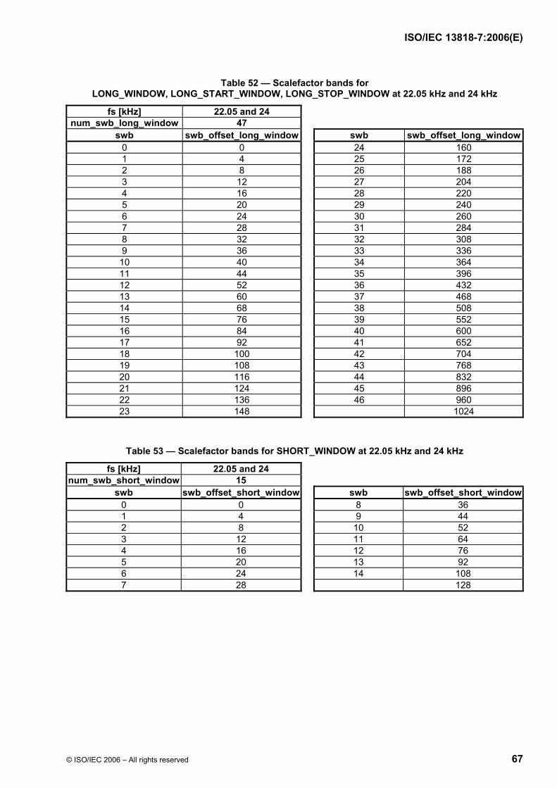
ISO/IEC 13818-7:2006(E)
© ISO/IEC 2006 – All rights reserved 67
Table 52 — Scalefactor bands for LONG_WINDOW, LONG_START_WINDOW, LONG_STOP_WINDOW at 22.05 kHz and 24 kHz
fs [kHz] 22.05 and 24 num_swb_long_window 47
swb swb_offset_long_window swb swb_offset_long_window0 0 24 160 1 4 25 172 2 8 26 188 3 12 27 204 4 16 28 220 5 20 29 240 6 24 30 260 7 28 31 284 8 32 32 308 9 36 33 336 10 40 34 364 11 44 35 396 12 52 36 432 13 60 37 468 14 68 38 508 15 76 39 552 16 84 40 600 17 92 41 652 18 100 42 704 19 108 43 768 20 116 44 832 21 124 45 896 22 136 46 960 23 148 1024
Table 53 — Scalefactor bands for SHORT_WINDOW at 22.05 kHz and 24 kHz
fs [kHz] 22.05 and 24 num_swb_short_window 15
swb swb_offset_short_window swb swb_offset_short_window0 0 8 36 1 4 9 44 2 8 10 52 3 12 11 64 4 16 12 76 5 20 13 92 6 24 14 108 7 28 128

ISO/IEC 13818-7:2006(E)
68 © ISO/IEC 2006 – All rights reserved
Table 54 — Scalefactor bands for LONG_WINDOW, LONG_START_WINDOW, LONG_STOP_WINDOW at 64 kHz
fs [kHz] 64 num_swb_long_window 47
swb swb_offset_long_window swb swb_offset_long_window0 0 24 172 1 4 25 192 2 8 26 216 3 12 27 240 4 16 28 268 5 20 29 304 6 24 30 344 7 28 31 384 8 32 32 424 9 36 33 464 10 40 34 504 11 44 35 544 12 48 36 584 13 52 37 624 14 56 38 664 15 64 39 704 16 72 40 744 17 80 41 784 18 88 42 824 19 100 43 864 20 112 44 904 21 124 45 944 22 140 46 984 23 156 1024
Table 55 — Scalefactor bands for SHORT_WINDOW at 64 kHz
fs [kHz] 64 num_swb_short_window 12
swb swb_offset_short_window swb swb_offset_short_window0 0 7 32 1 4 8 40 2 8 9 48 3 12 10 64 4 16 11 92 5 20 128 6 24

ISO/IEC 13818-7:2006(E)
© ISO/IEC 2006 – All rights reserved 69
Table 56 — Scalefactor bands for LONG_WINDOW, LONG_START_WINDOW, LONG_STOP_WINDOW at 88.2 kHz and 96 kHz
fs [kHz] 88.2 and 96 num_swb_long_window 41
swb swb_offset_long_window swb swb_offset_long_window0 0 21 120 1 4 22 132 2 8 23 144 3 12 24 156 4 16 25 172 5 20 26 188 6 24 27 212 7 28 28 240 8 32 29 276 9 36 30 320 10 40 31 384 11 44 32 448 12 48 33 512 13 52 34 576 14 56 35 640 15 64 36 704 16 72 37 768 17 80 38 832 18 88 39 896 19 96 40 960 20 108 1024
Table 57 — Scalefactor bands for SHORT_WINDOW at 88.2 kHz and 96 kHz
fs [kHz] 88.2 and 96 num_swb_short_window 12
swb swb_offset_short_window swb swb_offset_short_window0 0 7 32 1 4 8 40 2 8 9 48 3 12 10 64 4 16 11 92 5 20 128 6 24

ISO/IEC 13818-7:2006(E)
70 © ISO/IEC 2006 – All rights reserved
8.10 Figures
window_sequence = EIGHT_SHORT_SEQUENCE
num_windows = 8 grouping_bits = ‘1100101’ num_window_groups = 4
window group length[] = { 3, 1, 2, 2 }
3 2 1 0
0 1 2 3 4 5 6 7
group#
window#
Figure 4 — Example for short window grouping
sfb 2sfb 1sfb 0 . .. sfb (num_sfb-1)
Order of scalefactor bands for ONLY_LONG_SEQUENCE
spectral coefficients
Figure 5 — Spectral order of scalefactor bands in case of ONLY_LONG_SEQUENCE
win 2sfb 0win 1win 0
. ..win 2
sfb 1win 1win 0
sfb 2win 3
sfb 1win 3
sfb 0win 3
. ..
Order of scale factor bands for EIGHT_SHORT_SEQUENCEwindow_group_length[] = { 3, 1, ... }
group 0
spectral coefficients
group 1
Figure 6 — Spectral order of scalefactor bands in case of EIGHT_SHORT_SEQUENCE
9 Noiseless Coding
9.1 Tool Description
Noiseless coding is used to further reduce the redundancy of the scalefactors and the quantized spectrum of each audio channel.
The global_gain is coded as an 8 bit unsigned integer. The first scalefactor associated with the quantized spectrum is differentially coded relative to the global_gain value and then Huffman coded using the scalefactor codebook. The remaining scalefactors are differentially coded relative to the previous scalefactor and then Huffman coded using the scalefactor codebook.
Noiseless coding of the quantized spectrum relies on two divisions of the spectral coefficients. The first is a division into scalefactor bands that contain a multiple of 4 quantized spectral coefficients. See subclause 8.3.4 and 8.3.5.
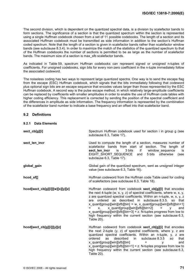
ISO/IEC 13818-7:2006(E)
© ISO/IEC 2006 – All rights reserved 71
The second division, which is dependent on the quantized spectral data, is a division by scalefactor bands to form sections. The significance of a section is that the quantized spectrum within the section is represented using a single Huffman codebook chosen from a set of 11 possible codebooks. The length of a section and its associated Huffman codebook must be transmitted as side information in addition to the section’s Huffman coded spectrum. Note that the length of a section is given in scalefactor bands rather than scalefactor window bands (see subclause 8.3.4). In order to maximize the match of the statistics of the quantized spectrum to that of the Huffman codebooks the number of sections is permitted to be as large as the number of scalefactor bands. The maximum size of a section is max_sfb scalefactor bands.
As indicated in Table 59, spectrum Huffman codebooks can represent signed or unsigned n-tuples of coefficients. For unsigned codebooks, sign bits for every non-zero coefficient in the n-tuple immediately follow the associated codeword.
The noiseless coding has two ways to represent large quantized spectra. One way is to send the escape flag from the escape (ESC) Huffman codebook, which signals that the bits immediately following that codeword plus optional sign bits are an escape sequence that encodes values larger than those represented by the ESC Huffman codebook. A second way is the pulse escape method, in which relatively large-amplitude coefficients can be replaced by coefficients with smaller amplitudes in order to enable the use of Huffman code tables with higher coding efficiency. This replacement is corrected by sending the position of the spectral coefficient and the differences in amplitude as side information. The frequency information is represented by the combination of the scalefactor band number to indicate a base frequency and an offset into that scalefactor band.
9.2 Definitions
9.2.1 Data Elements
sect_cb[g][i] Spectrum Huffman codebook used for section i in group g (see subclause 6.3, Table 17).
sect_len_incr Used to compute the length of a section, measures number of scalefactor bands from start of section. The length of sect_len_incr is 3 bits if window_sequence is EIGHT_SHORT_SEQUENCE and 5 bits otherwise (see subclause 6.3, Table 17).
global_gain Global gain of the quantized spectrum, sent as unsigned integer value (see subclause 6.3, Table 16).
hcod_sf[] Huffman codeword from the Huffman code Table used for coding of scalefactors (see subclause 6.3, Table 18).
hcod[sect_cb[g][i]][w][x][y][z] Huffman codeword from codebook sect_cb[g][i] that encodes the next 4-tuple (w, x, y, z) of spectral coefficients, where w, x, y, z are quantized spectral coefficients. Within an n-tuple, w, x, y, z are ordered as described in subclause 8.3.5. so that x_quant[group][win][sfb][bin] = w, x_quant[group][win][sfb][bin+1] = x, x_quant[group][win][sfb][bin+2] = y and x_quant[group][win][sfb][bin+3] = z. N-tuples progress from low to high frequency within the current section (see subclause 6.3, Table 20).
hcod[sect_cb[g][i]][y][z] Huffman codeword from codebook sect_cb[g][i] that encodes the next 2-tuple (y, z) of spectral coefficients, where y, z are quantized spectral coefficients. Within an n-tuple, y, z are ordered as described in subclause 8.3.5 so that x_quant[group][win][sfb][bin] = y and x_quant[group][win][sfb][bin+1] = z. N-tuples progress from low to high frequency within the current section (see subclause 6.3, Table 20).

ISO/IEC 13818-7:2006(E)
72 © ISO/IEC 2006 – All rights reserved
quad_sign_bits Sign bits for non-zero coefficients in the spectral 4-tuple. A ‘1’ indicates a negative coefficient, a ‘0’ a positive one. Bits associated with lower frequency coefficients are sent first (see subclause 6.3, Table 20).
pair_sign_bits Sign bits for non-zero coefficients in the spectral 2-tuple. A ‘1’ indicates a negative coefficient, a ‘0’ a positive one. Bits associated with lower frequency coefficients are sent first (see subclause 6.3, Table 20).
hcod_esc_y Escape sequence for quantized spectral coefficient y of 2-tuple (y,z) associated with the preceeding Huffman codeword (see subclause 6.3, Table 20).
hcod_esc_z Escape sequence for quantized spectral coefficient z of 2-tuple (y,z) associated with the preceeding Huffman codeword (see subclause 6.3, Table 20).
pulse_data_present 1 bit indicating whether the pulse escape is used (1) or not (0) (see subclause 6.3, Table 21). Note that pulse_data_present must be 0 for an EIGHT_SHORT_SEQUENCE.
number_pulse 2 bits indicating how many pulse escapes are used. The number of pulse escapes is from 1 to 4 (see subclause 6.3, Table 21).
pulse_start_sfb 6 bits indicating the index of the lowest scalefactor band where the pulse escape is achieved (see subclause 6.3, Table 21).
pulse_offset[i] 5 bits indicating the offset (see subclause 6.3, Table 21).
pulse_amp[i] 4 bits indicating the unsigned magnitude of the pulse (see subclause 6.3, Table 21).
9.2.2 Help Elements
sect_start[g][i] Offset to first scalefactor band in section i of group g (see subclause 6.3, Table 17).
sect_end[g][i] Offset to one higher than last scalefactor band in section i of group g (see subclause 6.3, Table 17).
num_sec[g] Number of sections in group g (see subclause 6.3, Table 17).
escape_flag The value of 16 in the ESC Huffman codebook
escape_prefix The bit sequence of N 1’s
escape_separator One 0 bit
escape_word An N+4 bit unsigned integer word, msb first
escape_sequence The sequence of escape_prefix, escape_separator and escape_word
escape_code 2^(N+4) + escape_word
x_quant[g][win][sfb][bin] Huffman decoded value for group g, window win, scalefactor band sfb, coefficient bin
spec[w][k] De-interleaved spectrum. w ranges from 0 to num_windows-1 and k ranges from 0 to swb_offset[num_swb]-1.

ISO/IEC 13818-7:2006(E)
© ISO/IEC 2006 – All rights reserved 73
The noiseless coding tool requires these constants (see subclause 6.3, spectral_data()).
ZERO_HCB 0
FIRST_PAIR_HCB 5
ESC_HCB 11
QUAD_LEN 4
PAIR_LEN 2
INTENSITY_HCB2 14
INTENSITY_HCB 15
ESC_FLAG 16
9.3 Decoding Process
Four-tuples or 2-tuples of quantized spectral coefficients are Huffman coded and transmitted starting from the lowest-frequency coefficient and progressing to the highest-frequency coefficient. For the case of multiple windows per block (EIGHT_SHORT_SEQUENCE), the grouped and interleaved set of spectral coefficients is treated as a single set of coefficients that progress from low to high. The set of coefficients may need to be de-interleaved after they are decoded (see subclause 8.3.5). Coefficients are stored in the array x_quant[g][win][sfb][bin], and the order of transmission of the Huffman codewords is such that when they are decoded in the order received and stored in the array, bin is the most rapidly incrementing index and g is the most slowly incrementing index. Within a codeword, for those associated with spectral four-tuples, the order of decoding is w, x, y, z; for codewords associated with spectral two-tuples, the order of decoding is y, z. The set of coefficients is divided into sections and the sectioning information is transmitted starting from the lowest frequency section and progressing to the highest frequency section. The spectral information for sections that are coded with the “zero” codebook is not sent as this spectral information is zero. Similarly, spectral information for sections coded with the “intensity” codebooks is not sent. The spectral information for all scalefactor bands at and above max_sfb, for which there is no section data, is zero.
There is a single differential scalefactor codebook which represents a range of values as shown in Table 58. The differential scalefactor codebook is shown in Table A.1 . There are eleven Huffman codebooks for the spectral data, as shown in Table 59. The codebooks are shown in Table A.2 through Table A.12 . There are three other “codebooks” above and beyond the actual Huffman codebooks, specifically the “zero” codebook, indicating that neither scalefactors nor quantized data will be transmitted, and the “intensity” codebooks indicating that this individual channel is part of a channel pair, and that the data that would normally be scalefactors is instead steering data for intensity stereo. In this case, no quantized spectral data are transmitted. Codebook indices 12 and 13 are reserved.
The spectrum Huffman codebooks encode 2- or 4-tuples of signed or unsigned quantized spectral coefficients, as shown in Table 59. This Table also indicates the largest absolute value (LAV) able to be encoded by each codebook and defines a boolean helper variable array, unsigned_cb[], that is 1 if the codebook is unsigned and 0 if signed.
The result of Huffman decoding each differential scalefactor codeword is the codeword index, listed in the first column of Table A.1 . This is translated to the desired differential scalefactor by adding index_offset to the index. Index_offset has a value of −60, as shown in Table 58. Likewise, the result of Huffman decoding each spectrum n-tuple is the codeword index, listed in the first column of Table A.2 through Table A.12 . This index is translated to the n-tuple spectral values as specified in the following pseudo C-code:
unsigned = Boolean value unsigned_cb[i], listed in second column of Table 59.
dim = Dimension of codebook, listed in the third column of Table 59.
lav = LAV, listed in the fourth column of Table 59.

ISO/IEC 13818-7:2006(E)
74 © ISO/IEC 2006 – All rights reserved
idx = codeword index
if (unsigned) { mod = lav + 1; off = 0; } else { mod = 2*lav + 1; off = lav; } if (dim == 4) { w = INT(idx/(mod*mod*mod)) - off; idx -= (w+off)*(mod*mod*mod) x = INT(idx/(mod*mod)) - off; idx -= (x+off)*(mod*mod) y = INT(idx/mod) - off; idx -= (y+off)*mod z = idx - off; } else { y = INT(idx/mod) - off; idx -= (y+off)*mod z = idx - off; }
If the Huffman codebook represents signed values, the decoding of the quantized spectral n-tuple is complete after Huffman decoding and translation of codeword index to quantized spectral coefficients. If the codebook represents unsigned values then the sign bits associated with non-zero coefficients immediately follow the Huffman codeword, with a ‘1’ indicating a negative coefficient and a ‘0’ indicating a positive one. For example, if a Huffman codeword from codebook 7
hcod[7][y][z]
has been parsed, then immediately following this in the bitstream is
pair_sign_bits
which is a variable length field of 0 to 2 bits. It can be parsed directly from the bitstream as
if (y != 0) if (one_sign_bit == 1) y = -y ; if (z != 0) if (one_sign_bit == 1) z = -z; where one_sign_bit is the next bit in the bitstream and pair_sign_bits is the concatenation of the one_sign_bit fields.
The ESC codebook is a special case. It represents values from 0 to 16 inclusive, but values from 0 to 15 encode actual data values, and the value16 is an escape_flag that signals the presence of hcod_esc_y or hcod_esc_z, either of which will be denoted as an escape_sequence. This escape_sequence permits quantized spectral elements of LAV>15 to be encoded. It consists of an escape_prefix of N 1’s, followed by an escape_separator of one zero, followed by an escape_word of N+4 bits representing an unsigned integer value. The escape_sequence has a decoded value of 2^(N+4)+escape_word. The desired quantized spectral coefficient is then the sign indicated by the pair_sign_bits applied to the value of the escape_sequence. In other words, an escape_sequence of 00000 would decode as 16, an escape_sequence of 01111 as 31, an escape_sequence of 1000000 as 32, one of 1011111 as 63, and so on. Note that restrictions in subclause 10.3 dictate that the length of the escape_sequence is always less than 22 bits. For escape Huffman codewords the ordering of data elements is Huffman codeword followed by 0 to 2 sign bits followed by 0 to 2 escape sequences.
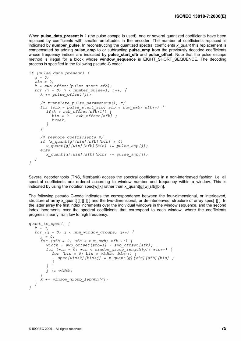
ISO/IEC 13818-7:2006(E)
© ISO/IEC 2006 – All rights reserved 75
When pulse_data_present is 1 (the pulse escape is used), one or several quantized coefficients have been replaced by coefficients with smaller amplitudes in the encoder. The number of coefficients replaced is indicated by number_pulse. In reconstructing the quantized spectral coefficients x_quant this replacement is compensated by adding pulse_amp to or subtracting pulse_amp from the previously decoded coefficients whose frequency indices are indicated by pulse_start_sfb and pulse_offset. Note that the pulse escape method is illegal for a block whose window_sequence is EIGHT_SHORT_SEQUENCE. The decoding process is specified in the following pseudo-C code:
if (pulse_data_present) { g = 0; win = 0; k = swb_offset[pulse_start_sfb]; for (j = 0; j < number_pulse+1; j++) { k += pulse_offset[j]; /* translate_pulse_parameters(); */ for (sfb = pulse_start_sfb; sfb < num_swb; sfb++) { if(k < swb_offset[sfb+1]) { bin = k - swb_offset[sfb] ; break; } } /* restore coefficients */ if (x_quant[g][win][sfb][bin] > 0) x_quant[g][win][sfb][bin] += pulse_amp[j]; else x_quant[g][win][sfb][bin] -= pulse_amp[j]; } }
Several decoder tools (TNS, filterbank) access the spectral coefficients in a non-interleaved fashion, i.e. all spectral coefficients are ordered according to window number and frequency within a window. This is indicated by using the notation spec[w][k] rather than x_quant[g][w][sfb][bin].
The following pseudo C-code indicates the correspondence between the four-dimensional, or interleaved, structure of array x_quant[ ][ ][ ][ ] and the two-dimensional, or de-interleaved, structure of array spec[ ][ ]. In the latter array the first index increments over the individual windows in the window sequence, and the second index increments over the spectral coefficients that correspond to each window, where the coefficients progress linearly from low to high frequency.
quant_to_spec() { k = 0; for (g = 0; g < num_window_groups; g++) { j = 0; for (sfb = 0; sfb < num_swb; sfb ++) { width = swb_offset[sfb+1] - swb_offset[sfb]; for (win = 0; win < window_group_length[g]; win++) { for (bin = 0; bin < width; bin++) { spec[win+k][bin+j] = x_quant[g][win][sfb][bin] ; } } j += width; } k += window_group_length[g]; } }
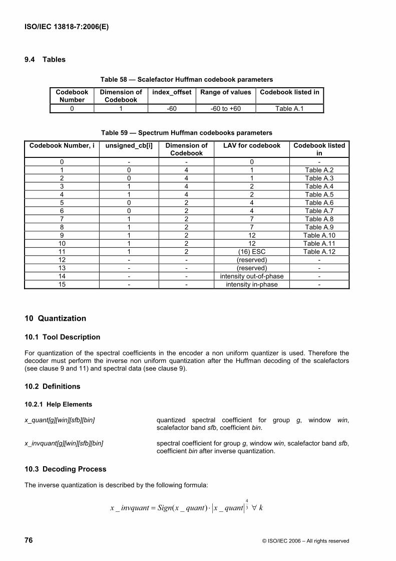
ISO/IEC 13818-7:2006(E)
76 © ISO/IEC 2006 – All rights reserved
9.4 Tables
Table 58 — Scalefactor Huffman codebook parameters
Codebook Number
Dimension of Codebook
index_offset Range of values Codebook listed in
0 1 -60 -60 to +60 Table A.1
Table 59 — Spectrum Huffman codebooks parameters
Codebook Number, i unsigned_cb[i] Dimension of Codebook
LAV for codebook Codebook listed in
0 - - 0 - 1 0 4 1 Table A.2 2 0 4 1 Table A.3 3 1 4 2 Table A.4 4 1 4 2 Table A.5 5 0 2 4 Table A.6 6 0 2 4 Table A.7 7 1 2 7 Table A.8 8 1 2 7 Table A.9 9 1 2 12 Table A.10 10 1 2 12 Table A.11 11 1 2 (16) ESC Table A.12 12 - - (reserved) - 13 - - (reserved) - 14 - - intensity out-of-phase - 15 - - intensity in-phase -
10 Quantization
10.1 Tool Description
For quantization of the spectral coefficients in the encoder a non uniform quantizer is used. Therefore the decoder must perform the inverse non uniform quantization after the Huffman decoding of the scalefactors (see clause 9 and 11) and spectral data (see clause 9).
10.2 Definitions
10.2.1 Help Elements
x_quant[g][win][sfb][bin] quantized spectral coefficient for group g, window win, scalefactor band sfb, coefficient bin.
x_invquant[g][win][sfb][bin] spectral coefficient for group g, window win, scalefactor band sfb, coefficient bin after inverse quantization.
10.3 Decoding Process
The inverse quantization is described by the following formula:
kquantxquantxSigninvquantx ∀⋅= 34
_)_(_

ISO/IEC 13818-7:2006(E)
© ISO/IEC 2006 – All rights reserved 77
The maximum allowed absolute amplitude for x_quant is 8191. The inverse quantization is applied as follows:
for (g = 0; g < num_window_groups; g++) { for (sfb = 0; sfb < max_sfb; sfb++) { width = (swb_offset [sfb+1] - swb_offset [sfb]); for (win = 0; win < window_group_len[g]; win++) {; for (bin = 0; bin < width; bin++) { x_invquant[g][win][sfb][bin] = sign(x_quant[g][win][sfb][bin]) * abs(x_quant[g][win][sfb][bin]) ^(4/3); } } } }
11 Scalefactors
11.1 Tool Description
The basic method to adjust the quantization noise in the frequency domain is the noise shaping using scalefactors. For this purpose the spectrum is divided in several groups of spectral coefficients called scalefactor bands which share one scalefactor (see subclause 8.3.4). A scalefactor represents a gain value which is used to change the amplitude of all spectral coefficients in that scalefactor band. This mechanism is used to change the allocation of the quantization noise in the spectral domain generated by the non uniform quantizer.
For window_sequences which contain SHORT_WINDOWs grouping can be applied, i.e. a specified number of consecutive SHORT_WINDOWs may have only one set of scalefactors. Each scalefactor is then applied to a group of scalefactor bands corresponding in frequency (see subclause 8.3.4).
In this tool the scalefactors are applied to the inverse quantized coefficients to reconstruct the spectral values.
11.2 Definitions
11.2.1 Data Functions
scale_factor_data() Part of bitstream which contains the differential coded scalefactors (see Table 18)
11.2.2 Data Elements
global_gain An 8-bit unsigned integer value representing the value of the first scalefactor. It is also the start value for the following differential coded scalefactors (see Table 16)
hcod_sf[] Huffman codeword from the Huffman code Table used for coding of scalefactors, see Table 18 and subclause 9.2
11.2.3 Help Elements
dpcm_sf[g][sfb] Differential coded scalefactor of group g, scalefactor band sfb.
x_rescal[] Rescaled spectral coefficients
sf[g][sfb] Array for scalefactors of each group
get_scale_factor_gain() Function that returns the gain value corresponding to a scalefactor

ISO/IEC 13818-7:2006(E)
78 © ISO/IEC 2006 – All rights reserved
11.3 Decoding Process
11.3.1 Scalefactor Bands
Scalefactors are used to shape the quantization noise in the spectral domain. For this purpose, the spectrum is divided into several scalefactor bands (see subclause 8.3.4). Each scalefactor band has a scalefactor, which represents a certain gain value which has to be applied to all spectral coefficients in this scalefactor band. In case of EIGHT_SHORT_SEQUENCE a scalefactor band may contain multiple scalefactor window bands of consecutive SHORT_WINDOWs (see subclause 8.3.4 and 8.3.5).
11.3.2 Decoding of Scalefactors
For all scalefactors the difference to the preceeding value is coded using the Huffman code book given in Table A.1 . See clause 9 for a detailed description of the Huffman decoding process. The start value is given explicitly as a 8 bit PCM in the data element global_gain. A scalefactor is not transmitted for scalefactor bands which are coded with the Huffman codebook ZERO_HCB. If the Huffman codebook for a scalefactor band is coded with INTENSITY_HCB or INTENSITY_HCB2, the scalefactor is used for intensity stereo (see clause 9 and subclause 12.2). In that case a normal scalefactor does not exist (but is initialized to zero to have a valid entry in the array).
The following pseudo code describes how to decode the scalefactors sf[g][sfb]:
last_sf = global_gain; for (g = 0; g < num_window_groups; g++) { for (sfb = 0; sfb < max_sfb; sfb++) { if (sfb_cb[g][sfb] != ZERO_HCB && sfb_cb[g][sfb] != INTENSITY_HCB && sfb_cb[g][sfb] != INTENSITY_HCB2) { dpcm_sf = decode_huffman() - index_offset; /* see clause 9*/ sf[g][sfb] = dpcm_sf + last_sf; last_sf = sf[g][sfb]; } else { sf[g][sfb] = 0; } } } Note that scalefactors, sf[g][sfb], must be within the range of zero to 255, both inclusive.
11.3.3 Applying Scalefactors
The spectral coefficients of all scalefactor bands which correspond to a scalefactor have to be rescaled according to their scalefactor. In case of a window sequence that contains groups of short windows all coefficients in grouped scalefactor window bands have to be scaled using the same scalefactor.
In case of window_sequences with only one window, the scalefactor bands and their corresponding coefficients are in spectral ascending order. In case of EIGHT_SHORT_SEQUENCE and grouping the spectral coefficients of grouped short windows are interleaved by scalefactor window bands. See subclause 8.3.5 for more detailed information.
The rescaling operation is done according to the following pseudo code:
for (g = 0; g < num_window_groups; g++) { for (sfb = 0; sfb < max_sfb; sfb++) { width = (swb_offset [sfb+1] - swb_offset [sfb] ); for (win = 0; win < window_group_len[g]; win++) {; gain = get_scale_factor_gain(sf[g][sfb]); for (k = 0; k < width; k++) { x_rescal[g][window][sfb][k] = x_invquant[g][window][sfb][k] * gain; }

ISO/IEC 13818-7:2006(E)
© ISO/IEC 2006 – All rights reserved 79
} } } The function get_scale_factor_gain(sf[g][sfb]) returns the gain factor that corresponds to a scalefactor. The return value follows the equation:
)_]][[(25.02 OFFSETSFsfbgsfgain −⋅=
The constant SF_OFFSET must be set to 100.
The following pseudo code describes this operation:
get_scale_factor_gain( sf[g][sfb] ) { SF_OFFSET = 100; gain = 2^(0.25 * ( sf[g][sfb] - SF_OFFSET)); return (gain); }
12 Joint Coding
12.1 M/S Stereo
12.1.1 Tool Description
The M/S joint channel coding operates on channel pairs. Channels are most often paired such that they have symmetric presentation relative to the listener, such as left/right or left surround/right surround. The first channel in the pair is denoted “left” and the second “right.” On a per-spectral-coefficient basis, the vector formed by the left and right channel signals is reconstructed or de-matrixed by either the identity matrix
⎥⎦
⎤⎢⎣
⎡⎥⎦
⎤⎢⎣
⎡=⎥
⎦
⎤⎢⎣
⎡rl
rl
1001
or the inverse M/S matrix
⎥⎦
⎤⎢⎣
⎡⎥⎦
⎤⎢⎣
⎡−
=⎥⎦
⎤⎢⎣
⎡sm
rl
1111
The decision on which matrix to use is done on a scalefactor band by scalefactor band basis as indicated by the ms_used flags. M/S joint channel coding can only be used if common_window is ‘1’ (see subclause 8.3.1).
12.1.2 Definitions
12.1.2.1 Data Elements
ms_mask_present This two bit field indicates that the MS mask is
00 All zeros
01 A mask of max_sfb bands of ms_used follows this field
10 All ones
11 Reserved
(see subclause 6.3, Table 14)
ms_used[g][sfb] One-bit flag per scalefactor band indicating that M/S coding is being used in windowgroup g and scalefactor band sfb (see subclause 6.3, Table 14).

ISO/IEC 13818-7:2006(E)
80 © ISO/IEC 2006 – All rights reserved
12.1.2.2 Help Elements
l_spec[] Array containing the left channel spectrum of the respective channel pair.
r_spec[] Array containing the right channel spectrum of the respective channel pair.
is_intensity(g,sfb) Function returning the intensity status, defined in 12.2.3
12.1.3 Decoding Process
Reconstruct the spectral coefficients of the first (“left”) and second (“right”) channel as specified by the mask_present and the ms_used[][] flags as follows:
if (mask_present >= 1) { for (g = 0; g < num_window_groups; g++) { for (b = 0; b < window_group_length[g]; b++) { for (sfb = 0; sfb < max_sfb; sfb++) { if ((ms_used[g][sfb] || mask_present == 2) && !is_intensity(g,sfb)) { for (i = 0; i < swb_offset[sfb+1]-swb_offset[sfb]; i++) { tmp = l_spec[g][b][sfb][i] - r_spec[g][b][sfb][i]; l_spec[g][b][sfb][i] = l_spec[g][b][sfb][i] + r_spec[g][b][sfb][i]; r_spec[g][b][sfb][i] = tmp; } } } } } }
Please note that ms_used[][] is also used in the context of intensity stereo coding. If intensity stereo coding is on for a particular scalefactor band, no M/S stereo decoding is carried out.
12.2 Intensity Stereo
12.2.1 Tool Description
This tool is used to implement joint intensity stereo coding between both channels of a channel pair. Thus, both channel outputs are derived from a single set of spectral coefficients after the inverse quantization process. This is done selectively on a scalefactor band basis when intensity stereo is flagged as active.
12.2.2 Definitions
12.2.2.1 Data Elements
hcod_sf[] Huffman codeword from the Huffman code Table used for coding of scalefactors (see subclause 9.2)
12.2.2.2 Help Elements
dpcm_is_position[][] Differentially encoded intensity stereo position
is_position[group][sfb] Intensity stereo position for each group and scalefactor band
l_spec[] Array containing the left channel spectrum of the respective channel pair
r_spec[] Array containing the right channel spectrum of the respective channel pair
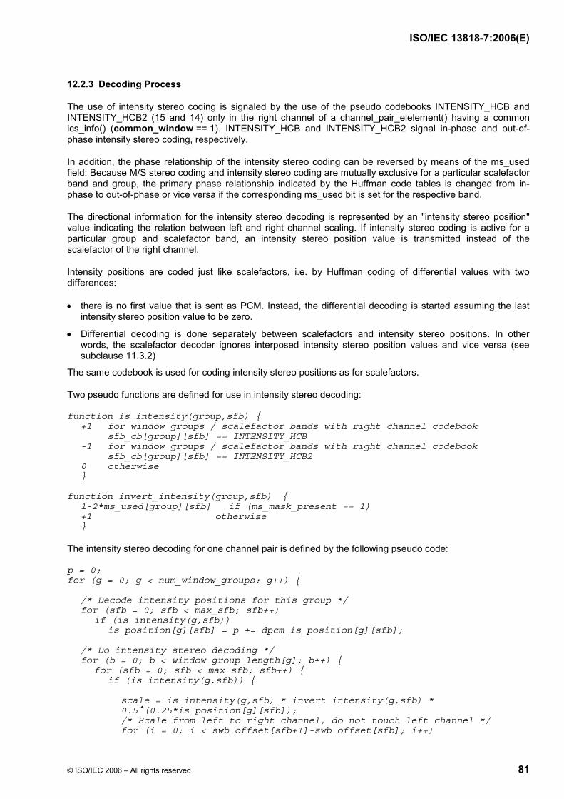
ISO/IEC 13818-7:2006(E)
© ISO/IEC 2006 – All rights reserved 81
12.2.3 Decoding Process
The use of intensity stereo coding is signaled by the use of the pseudo codebooks INTENSITY_HCB and INTENSITY_HCB2 (15 and 14) only in the right channel of a channel_pair_elelement() having a common ics_info() (common_window == 1). INTENSITY_HCB and INTENSITY_HCB2 signal in-phase and out-of-phase intensity stereo coding, respectively.
In addition, the phase relationship of the intensity stereo coding can be reversed by means of the ms_used field: Because M/S stereo coding and intensity stereo coding are mutually exclusive for a particular scalefactor band and group, the primary phase relationship indicated by the Huffman code tables is changed from in-phase to out-of-phase or vice versa if the corresponding ms_used bit is set for the respective band.
The directional information for the intensity stereo decoding is represented by an "intensity stereo position" value indicating the relation between left and right channel scaling. If intensity stereo coding is active for a particular group and scalefactor band, an intensity stereo position value is transmitted instead of the scalefactor of the right channel.
Intensity positions are coded just like scalefactors, i.e. by Huffman coding of differential values with two differences:
• there is no first value that is sent as PCM. Instead, the differential decoding is started assuming the last intensity stereo position value to be zero.
• Differential decoding is done separately between scalefactors and intensity stereo positions. In other words, the scalefactor decoder ignores interposed intensity stereo position values and vice versa (see subclause 11.3.2)
The same codebook is used for coding intensity stereo positions as for scalefactors.
Two pseudo functions are defined for use in intensity stereo decoding:
function is_intensity(group,sfb) { +1 for window groups / scalefactor bands with right channel codebook sfb_cb[group][sfb] == INTENSITY_HCB -1 for window groups / scalefactor bands with right channel codebook sfb_cb[group][sfb] == INTENSITY_HCB2 0 otherwise } function invert_intensity(group,sfb) { 1-2*ms_used[group][sfb] if (ms_mask_present == 1) +1 otherwise }
The intensity stereo decoding for one channel pair is defined by the following pseudo code:
p = 0; for (g = 0; g < num_window_groups; g++) { /* Decode intensity positions for this group */ for (sfb = 0; sfb < max_sfb; sfb++) if (is_intensity(g,sfb)) is_position[g][sfb] = p += dpcm_is_position[g][sfb]; /* Do intensity stereo decoding */ for (b = 0; b < window_group_length[g]; b++) { for (sfb = 0; sfb < max_sfb; sfb++) { if (is_intensity(g,sfb)) { scale = is_intensity(g,sfb) * invert_intensity(g,sfb) * 0.5^(0.25*is_position[g][sfb]); /* Scale from left to right channel, do not touch left channel */ for (i = 0; i < swb_offset[sfb+1]-swb_offset[sfb]; i++)

ISO/IEC 13818-7:2006(E)
82 © ISO/IEC 2006 – All rights reserved
r_spec[g][b][sfb][i] = scale * l_spec[g][b][sfb][i]; } } } }
12.2.4 Integration with Intra Channel Prediction Tool
For scalefactor bands coded in intensity stereo the corresponding predictors in the right channel are switched to "off" thus effectively overriding the status specified by the prediction_used mask. The update of these predictors is done by feeding the intensity stereo decoded spectral values of the right channel as the "last quantized value" xrec(n-1). These values result from the scaling process from left to right channel as described in the pseudo code.
12.3 Coupling Channel
12.3.1 Tool Description
Coupling channel elements provide two functionalities: First, coupling channels may be used to implement generalized intensity stereo coding where channel spectra can be shared across channel boundaries. Second, coupling channels may be used to dynamically perform a downmix of one sound object into the stereo image.
Note that this tool includes certain profile dependent parameters (see subclause 7.1).
12.3.2 Definitions
12.3.2.1 Data Elements
ind_sw_cce_flag One bit indicating whether the coupled target syntax element is an independently switched (1) or a dependently switched (0) CCE (see subclause 6.3, Table 22).
num_coupled_elements Number of coupled target channels is equal to num_coupled_elements+1. The minimum value is 0 indicating 1 coupled target channel (see subclause 6.3, Table 22).
cc_target_is_cpe One bit indicating if the coupled target syntax element is a CPE (1) or a SCE (0) (see subclause 6.3, Table 22).
cc_target_tag_select Four bit field specifying the element_instance_tag of the coupled target syntax element (see subclause 6.3, Table 22).
cc_l One bit indicating that a list of gain_element values is applied to the left channel of a channel pair (see subclause 6.3, Table 22).
cc_r One bit indicating that a list of gain_element values is applied to the right channel of a channel pair (see subclause 6.3, Table 22).
cc_domain One bit indicating whether the coupling is performed before (0) or after (1) the TNS decoding of the coupled target channels (see subclause 6.3, Table 22).

ISO/IEC 13818-7:2006(E)
© ISO/IEC 2006 – All rights reserved 83
gain_element_sign One bit indicating if the transmitted gain_element values contain information about in-phase / out-of-phase coupling (1) or not (0) (see subclause 6.3, Table 22).
gain_element_scale Determines the amplitude resolution cc_scale of the scaling operation according to Table 61 (see subclause 6.3, Table 22).
common_gain_element_present[c] One bit indicating whether Huffman coded common_gain_element values are transmitted (1) or whether Huffman coded differential gain_elements are sent (0) (see subclause 6.3, Table 22).
12.3.2.2 Help Elements
dpcm_gain_element[][] Differentially encoded gain element.
gain_element[group][sfb] Gain element for each group and scalefactor band.
common_gain_element[] Gain element that is used for all window groups and scalefactor bands of one coupling target channel.
spectrum_m(idx, domain) Pointer to the spectral data associated with the single_channel_element() with index idx. Depending on the value of "domain", the spectral coefficients before (0) or after (1) TNS decoding are pointed to.
spectrum_l(idx, domain) Pointer to the spectral data associated with the left channel of the channel_pair_element() with index idx. Depending on the value of "domain", the spectral coefficients before (0) or after (1) TNS decoding are pointed to.
spectrum_r(idx, domain) Pointer to the spectral data associated with the right channel of the channel_pair_element() with index idx. Depending on the value of "domain", the spectral coefficients before (0) or after (1) TNS decoding are pointed to.
12.3.3 Decoding Process
The coupling channel is based on an embedded single_channel_element() which is combined with some dedicated fields to accomodate its special purpose.
The coupled target syntax elements (SCEs or CPEs) are addressed using two syntax elements. First, the cc_target_is_cpe field selects whether a SCE or CPE is addressed. Second, a cc_target_tag_select field selects the instance_tag of the SCE/CPE.
The scaling operation involved in channel coupling is defined by gain_element values which describe the applicable gain factor and sign. In accordance with the coding procedures for scalefactors and intensity stereo positions, gain_element values are differentially encoded using the Huffman Table for scalefactors. Similarly, the decoded gain factors for coupling relate to window groups of spectral coefficients.
Independently switched CCEs vs. dependently switched CCEs
There are two kinds of CCEs. They are “independently switched” and “dependently switched” CCEs. An independently switched CCE is a CCE in which the window state (i.e. window_sequence and window_shape) of the CCE does not have to match that of any of the SCE or CPE channels that the CCE is coupled onto (target channels). This has several important implications:
• First, it is required that an independently switched CCE must only use the common_gain element, not a list of gain_elements.

ISO/IEC 13818-7:2006(E)
84 © ISO/IEC 2006 – All rights reserved
• Second, the independently switched CCE must be decoded all the way to the time domain (i.e. including the synthesis filterbank) before it is scaled and added onto the various SCE and CPE channels that it is coupled to in the case that window state does not match.
A dependently switched CCE, on the other hand, must have a window state that matches all of the target SCE and CPE channels that it is coupled onto as determined by the list of cc_l and cc_r elements. In this case, the CCE only needs to be decoded as far as the frequency domain and then scaled as directed by the gain list before it is added to the target SCE or CPE channels.
The following pseudo code in function decode_ coupling_channel() defines the decoding operation for a dependently switched coupling channel element. First the spectral coefficients of the embedded single_channel_element() are decoded into an internal buffer. Since the gain elements for the first coupled target (list_index == 0) are not transmitted, all gain_element values associated with this target are assumed to be 0, i.e. the coupling channel is added to the coupled target channel in its natural scaling. Otherwise the spectral coefficients are scaled and added to the coefficients of the coupled target channels using the appropriate list of gain_element values.
An independently switched CCE is decoded like a dependently switched CCE having only common_gain_element’s. However, the resulting scaled spectrum is transformed back into its time representation and then coupled in the time domain.
Please note that the gain_element lists may be shared between the left and the right channel of a target channel pair element. This is signalled by both cc_l and cc_r being zero as indicated in the Table below:
Table 60 — Sharing of gain_element lists
cc_l, cc_r
shared gain list present
left gain list present
right gain list present
0, 0 yes no no 0, 1 no no yes 1, 0 no yes no 1, 1 no yes yes
decode_coupling_channel() { - decode spectral coefficients of embedded single_channel_element into buffer "cc_spectrum[]". /* Couple spectral coefficients onto target channels */ list_index = 0; for (c = 0; c < num_coupled_elements+1; c++) { if (!cc_target_is_cpe[c]) { couple_channel(cc_spectrum, spectrum_m(cc_target_tag_select[c], cc_domain), list_index++); } if (cc_target_is_cpe[c]) { if (!cc_l[c] && !cc_r[c]) { couple_channel(cc_spectrum, spectrum_l(cc_target_tag_select[c], cc_domain), list_index); couple_channel(cc_spectrum, spectrum_r(cc_target_tag_select[c], cc_domain), list_index++); } if (cc_l[c]) { couple_channel(cc_spectrum, spectrum_l(cc_target_tag_select[c], cc_domain ), list_index++)); }

ISO/IEC 13818-7:2006(E)
© ISO/IEC 2006 – All rights reserved 85
if (cc_r[c]) { couple_channel(cc_spectrum, spectrum_r(cc_target_tag_select[c], cc_domain ), list_index++)); } } } }
couple_channel(source_spectrum[], dest_spectrum[], gain_list_index) { idx = gain_list_index; a = 0; cc_scale = cc_scale_table[gain_element_scale]; for (g = 0; g < num_window_groups; g++) { /* Decode coupling gain elements for this group */ if (common_gain_element_present[idx]) { for (sfb = 0; sfb < max_sfb; sfb++) { cc_sign[idx][g][sfb] = 1; gain_element[idx][g][sfb] = common_gain_element[idx]; } } else { for (sfb = 0; sfb < max_sfb; sfb++) { if (sfb_cb[g][sfb] == ZERO_HCB) continue; if (gain_element_sign) { cc_sign[idx][g][sfb] = 1 - 2*(dpcm_gain_element[idx][g][sfb] & 0x1); gain_element[idx][g][sfb] = a += (dpcm_gain_element[idx][g][sfb] >> 1); } else { cc_sign[idx][g][sfb] = 1; gain_element[idx][g][sfb] = a += dpcm_gain_element[idx][g][sfb]; } } } /* Do coupling onto target channels */ for (b = 0; b < window_group_length[b]; b++) { for (sfb = 0; sfb < max_sfb; sfb++) { if (sfb_cb[g][sfb] != ZERO_HCB) { cc_gain[idx][g][sfb] = cc_sign[idx][g][sfb] * cc_scale^gain_element[idx][g][sfb]; for (i = 0; i<swb_offset[sfb+1]-swb_offset[sfb]; i++) dest_spectrum[g][b][sfb][i] += cc_gain[idx][g][sfb] * source_spectrum[g][b][sfb][i]; } } } } } Note: The array sfb_cb represents the codebook data respect to the CCE’s embedded single_channel_element() (not the coupled target channel).

ISO/IEC 13818-7:2006(E)
86 © ISO/IEC 2006 – All rights reserved
12.3.4 Tables
Table 61 — Scaling resolution for channel coupling (cc_scale_table)
Value of "gain_element_scale" Amplitude Resolution "cc_scale" Stepsize [dB] 0 2^(1/8) 0.75 1 2^(1/4) 1.50 2 2^(1/2) 3.00 3 2^1 6.00
13 Prediction
13.1 Tool Description
Prediction is used for an improved redundancy reduction and is especially effective in case of more or less stationary parts of a signal which belong to the most demanding parts in terms of required bitrate. Prediction can be applied to every channel using an intra channel (or mono) predictor which exploits the auto-correlation between the spectral components of consecutive frames. Because a window_sequence of type EIGHT_SHORT_SEQUENCE indicates signal changes, i.e. non-stationary signal characteristics, prediction is only used if window_sequence is of type ONLY_LONG_SEQUENCE, LONG_START_SEQUENCE or LONG_STOP_SEQUENCE. The use of the prediction tool is profile dependent. See clause 7 for detailed information.
For each channel prediction is applied to the spectral components resulting from the spectral decomposition of the filterbank. For each spectral component up to limit specified by PRED_SFB_MAX, there is one corresponding predictor resulting in a bank of predictors, where each predictor exploits the auto-correlation between the spectral component values of consecutive frames.
The overall coding structure using a filterbank with high spectral resolution implies the use of backward adaptive predictors to achieve high coding efficiency. In this case, the predictor coefficients are calculated from preceding quantized spectral components in the encoder as well as in the decoder and no additional side information is needed for the transmission of predictor coefficients - as would be required for forward adaptive predictors. A second order backward-adaptive lattice structure predictor is used for each spectral component, so that each predictor is working on the spectral component values of the two preceding frames. The predictor parameters are adapted to the current signal statistics on a frame by frame base, using an LMS based adaptation algorithm. If prediction is activated, the quantizer is fed with a prediction error instead of the original spectral component, resulting in a coding gain.
In order to keep storage requirements to a minimum, predictor state variables are quantized prior to storage.
13.2 Definitions
13.2.1 Data Elements
predictor_data_present 1 bit indicating whether prediction is used in current frame (1) or not (0) (always present for ONLY_LONG_SEQUENCE, LONG_START_SEQUENCE and LONG_STOP_SEQUENCE, see subclause 6.3, Table 15).
predictor_reset 1 bit indicating whether predictor reset is applied in current frame (1) or not (0) (only present if predictor_data_present flag is set, see subclause 6.3, Table 15).
predictor_reset_group_number 5 bit number specifying the reset group to be reset in current frame if predictor reset is enabled (only present if predictor_reset flag is set, see subclause 6.3, Table 15).

ISO/IEC 13818-7:2006(E)
© ISO/IEC 2006 – All rights reserved 87
prediction_used 1 bit for each scalefactor band (sfb) where prediction can be used indicating whether prediction is switched on (1) / off (0) in that sfb. If max_sfb is less than PRED_SFB_MAX then for i greater than or equal to max_sfb, prediction_used[i] is not transmitted and therfore is set to off (0) (only present if predictor_data_present flag is set, see subclause 6.3, Table 15).
The following Table specifies the upper limit of scalefactor bands up to which prediction can be used:
Table 62 — Upper spectral limit for prediction
Sampling Frequency (Hz)
Pred_SFB_MAX Number of Predictors Maximum Frequency using Prediction (Hz)
96000 33 512 24000.00 88200 33 512 22050.00 64000 38 664 20750.00 48000 40 672 15750.00 44100 40 672 14470.31 32000 40 672 10500.00 24000 41 652 7640.63 22050 41 652 7019.82 16000 37 664 5187.50 12000 37 664 3890.63 11025 37 664 3574.51 8000 34 664 2593.75
This means that at 48 kHz sampling rate prediction can be used in scalefactor bands 0 through 39. According to Table 46 these 40 scalefactor bands include the MDCT lines 0 through 671, hence resulting in max. 672 predictors.
13.3 Decoding Process
For each spectral component up to the limit specified by PRED_SFB_MAX of each channel there is one predictor. Prediction is controlled on a single_channel_element() or channel_pair_element() basis by the transmitted side information in a two step approach, first for the whole frame at all and then conditionally for each scalefactor band individually, see subclause 13.3.1. The predictor coefficients for each predictor are calculated from preceding reconstructed values of the corresponding spectral component. The details of the required predictor processing are described in subclause 13.3.2. At the start of the decoding process, all predictors are initialized. The initialization and a predictor reset mechanism are described in subclause 13.3.2.4.
13.3.1 Predictor Side Information
The following description is valid for either one single_channel_element() or one channel_pair_element() and has to be applied to each such element. For each frame the predictor side information has to be extracted from the bitstream to control the further predictor processing in the decoder. In case of a single_channel_element() the control information is valid for the predictor bank of the channel associated with that element. In case of a channel_pair_element() there are the following two possibilities: If common_window = 1 then there is only one set of the control information which is valid for the two predictor banks of the two channels associated with that element. If common_window = 0 then there are two sets of control information, one for each of the two predictor banks of the two channels associated with that element.
If window_sequence is of type ONLY_LONG_SEQUENCE, LONG_START_SEQUENCE or LONG_STOP_SEQUENCE, the predictor_data_present bit is read. If this bit is not set (0) then prediction is switched off at all for the current frame and there is no further predictor side information present. In this case the prediction_used bit for each scalefactor band stored in the decoder has to be set to zero. If the

ISO/IEC 13818-7:2006(E)
88 © ISO/IEC 2006 – All rights reserved
predictor_data_present bit is set (1) then prediction is used for the current frame and the predictor_reset bit is read which determines whether predictor reset is applied in the current frame (1) or not (0). If predictor_reset is set then the next 5 bits are read giving a number specifying the group of predictors to be reset in the current frame, see also subclause 13.3.2.4 for the details. If the predictor_reset is not set then there is no 5 bit number in the bitstream. Next, the prediction_used bits are read from the bitstream, which control the use of prediction in each scalefactor band individually, i.e. if the bit is set for a particular scalefactor band, then prediction is enabled for all spectral components of this scalefactor band and the quantized prediction error of each spectral component is transmitted instead of the quantized value of the spectral component. Otherwise, prediction is disabled for this scalefactor band and the quantized values of the spectral components are transmitted.
13.3.2 Predictor Processing
13.3.2.1 General
The following description is valid for one single predictor and has to be applied to each predictor. A second order backward adaptive lattice structure predictor is used. Figure 7 shows the corresponding predictor flow graph on the decoder side. In principle, an estimate xest(n) of the current value of the spectral component x(n) is calculated from preceding reconstructed values xrec(n-1) and xrec(n-2), stored in the register elements of the predictor structure, using the predictor coefficients k1(n) and k2(n). This estimate is then added to the quantized prediction error eq(n) reconstructed from the transmitted data resulting in the reconstructed value xrec(n) of the current spectral component x(n). Figure 8 shows the block diagram of this reconstruction process for one single predictor.
Due to the realization in a lattice structure, the predictor consists of two so-called basic elements which are cascaded. In each element, the part xest,m(n), m=1, 2 of the estimate is calculated according to
)1()()( 1,, −⋅⋅= − nrnkbnx mqmmest ,
where
( )r n ax nq rec, ( )0 = ,
r n a r n b k n e nq q q, , ,( ) ( ( ) ( ) ( ))1 0 1 01= − − ⋅ ⋅
and )()()( ,1,, nxnene mestmqmq −= − .
Hence, the overall estimate results to:
)()()( 2,1, nxnxnx estestest +=
The constants
a and b , 1,0 ≤< ba
are attenuation factors which are included in each signal path contributing to the recursivity of the structure for the purpose of stabilization. By this means, possible oscillations due to transmission errors or drift between predictor coefficients on the encoder and decoder side due to numerical inaccuracy can be faded out or even prevented.
In the case of stationary signals and with a = b = 1, the predictor coefficient of element m is calculated by
[ ][ ] [ ]( ))1()(
)1()(2
1,2
1,21
1,1,
−+⋅−⋅
=−−
−−
nrEneEnrneE
kmqmq
mqmqm , 2,1=m and )()()( 0,0, nxnrne recqq ==

ISO/IEC 13818-7:2006(E)
© ISO/IEC 2006 – All rights reserved 89
In order to adapt the coefficients to the current signal properties, the expected values in the above equation are substituted by time average estimates measured over a limited past signal period. A compromise has to be chosen between a good convergence against the optimum predictor setting for signal periods with quasi stationary characteristic and the ability of fast adaptation in case of signal transitions. In this context algorithms with iterative improvement of the estimates, i.e. from sample to sample, are of special interest. Here, a "least mean square" (LMS) approach is used and the predictor coefficients are calculated as follows
)()(
)1(nVARnCOR
nkm
mm =+
with
)()1()1()( 1,1, nenrnCORnCOR mqmqmm −− ⋅−+−⋅= α
( ))()1(5.0)1()( 21,
21, nenrnVARnVAR mqmqmm −− +−⋅+−⋅= α
where α is an adaptation time constant which determines the influence of the current sample on the estimate of the expected values. The value of α is chosen to
90625.0=α .
The optimum values of the attenuation factors a and b have to be determined as a compromise between high prediction gain and small fade out time. The chosen values are
953125.0== ba .
Independent of whether prediction is disabled - either at all or only for a particular scalefactor band - or not, all the predictors are run all the time in order to always adapt the coefficients to the current signal statistics.
If window_sequence is of type ONLY_LONG_SEQUENCE, LONG_START_SEQUENCE and LONG_STOP_SEQUENCE only the calculation of the reconstructed value of the quantized spectral components differs depending on the value of the prediction_used bit:
• If the bit is set (1), then the quantized prediction error reconstructed from the transmitted data is added to the estimate xest(n) calculated by the predictor resulting in the reconstructed value of the quantized spectral component, i.e. )()()( nenxnx qestrec +=
• If the bit is not set (0), then the quantized value of the spectral component is reconstructed directly from the transmitted data.
In case of short blocks, i.e. window_sequence is of type EIGHT_SHORT_SEQUENCE, prediction is always disabled and a reset is carried out for all predictors in all scalefactor bands, which is equivalent to a reinitialization, see subclause 13.3.2.4.
For a single_channel_element(), the predictor processing for one frame is done according to the following pseudo code:
(It is assumed that the reconstructed value y_rec(c) - which is either the reconstructed quantized prediction error or the reconstructed quantized spectral coefficient - is available from previous processing.)
if (ONLY_LONG_SEQUENCE || LONG_START_SEQUENCE || LONG_STOP_SEQUENCE) { for (sfb = 0; sfb < PRED_SFB_MAX; sfb++) { fc = swb_offset_long_window[fs_index][sfb]; lc = swb_offset_long_window[fs_index][sfb+1]; for (c = fc; c < lc; c++) { x_est[c] = predict(); if (predictor_data_present && prediction_used[sfb])

ISO/IEC 13818-7:2006(E)
90 © ISO/IEC 2006 – All rights reserved
x_rec[c] = x_est[c] + y_rec[c]; else x_rec[c] = y_rec[c]; } } } else { reset_all_predictors(); }
In case of channel_pair_element()´s with common_window = 1, the only difference is that the computation of x_est and x_rec in the inner for loop is done for both channels associated with the channel_pair_element(). In case of channel_pair_element()´s with common_window = 0, each channel has prediction applied using that channel’s prediction side information.
13.3.2.2 Quantization in Predictor Calculations
For a given predictor six state variables need to be saved: r0, r1, COR1, COR2, VAR1 and VAR2. These variables will be saved as truncated IEEE floating-point numbers (i.e. the 16 msb of a float storage word).
The predicted value xest will be rounded to a 16-bit floating point representation (i.e. round to a 7-bit mantissa) prior to being used in any calculation. The exact rounding algorithm to be used is shown in pseudo-C function flt_round_inf(). Note that for complexity considerations, round to nearest, infinity is used instead of round to nearest, even.
The expressions (b / VAR1) and (b / VAR2) will be rounded to a 16-bit floating point representation (i.e. round to a 7-bit mantissa), which permits the ratio to be computed via a pair of small look-up tables. C-code for generating such tables is shown in pseudo-C function make_inv_tables().
All intermediate results in every floating point computation in the prediction algorithm will be represented in single precision floating point using rounding described below.
The IEEE Floating Point computational unit used in executing all arithmetic in the prediction tool will enable the following options:
• Round-to-Nearest, Even - Round to nearest representable value; round to the value with the least significant bit equal to zero (even) when the two nearest representable values are equally near.
• Overflow exception - Values whose magnitude is greater than the largest representable value will be set to the representation for infinty.
• Underflow exception - Gradual underflow (de-normalized numbers) will be supported; values whose magnitude is less than the smallest representable value will be set to zero.
13.3.2.3 Fast Algorithm for Rounding
/* this does not conform to IEEE conventions of round to * nearest, even, but it is fast */ static void flt_round_inf(float *pf) { int flg; unsigned long tmp, tmp1, tmp2; tmp = *(unsigned long*)pf; flg = tmp & (unsigned long)0x00008000; tmp &= (unsigned long)0xffff0000; tmp1 = tmp; /* round 1/2 lsb toward infinity */ if (flg) {

ISO/IEC 13818-7:2006(E)
© ISO/IEC 2006 – All rights reserved 91
tmp &= (unsigned long)0xff800000; /* extract exponent and sign */ tmp |= (unsigned long)0x00010000; /* insert 1 lsb */ tmp2 = tmp; /* add 1 lsb and elided one */ tmp &= (unsigned long)0xff800000; /* extract exponent and sign */ *pf = *(float*)&tmp1+*(float*)&tmp2-*(float*)&tmp; /* subtract elided one */ } else { *pf = *(float*)&tmp; } }
13.3.2.4 Generating Rounded b / Var
static float mnt_table[128]; static float exp_table[256]; /* function flt_round_even() only works for arguments in the range * 1.0 < *pf < 2.0 - 2^-24 */ static void flt_round_even(float *pf) { int exp,a; float tmp; frexp((double)*pf, &exp); tmp = *pf * (1<<(8-exp)); a = (int)tmp; if ((tmp-a) >= 0.5) a++; if ((tmp-a) == 0.5) a&=-2; *pf = (float)a/(1<<(8-exp)); } static void make_inv_tables(void) { int i; unsigned long tmp1, tmp; float *pf = (float *)&tmp1; float ftmp; *pf = 1.0; for (i=0; i<128; i++) { tmp = tmp1 + (i<<16); /* float 1.m, 7 msb only */ ftmp = b / *(float*)&tmp; flt_round_even(&ftmp); /* round to 16 bits */ mnt_table[i] = ftmp; } for (i=0; i<256; i++) { tmp = (i<<23); /* float 1.0 * 2^exp */ if (*(float*)&tmp > 1.0) { ftmp = 1.0 / *(float*)&tmp; } else { ftmp = 0; } exp_table[i] = ftmp; } }
13.3.3 Predictor Reset
Initialization of a predictor means that the predictor’s state variables are set as follows: r0 = r1 = 0, COR1 = COR2 = 0, VAR1 = VAR2 = 1. When the decoding process is started, all predictors are initialized.

ISO/IEC 13818-7:2006(E)
92 © ISO/IEC 2006 – All rights reserved
A cyclic reset mechanism is applied by the encoder and signaled to the decoder, in which all predictors are initialized again in a certain time interval in an interleaved way. On one hand this increases predictor stability by re-synchronizing the predictors of the encoder and the decoder and on the other hand it allows defined entry points in the bitstream.
The whole set of predictors is subdivided into 30 so-called reset groups according to the following table:
Table 63 — Predictor reset groups
Reset group number
Predictors of reset group
1 P0, P30, P60, P90,... 2 P1, P31, P61, P91,... 3 P2, P32, P62, P92,... ... 30 P29, P59, P89, P119,...
where Pi is the predictor which corresponds to the spectral coefficient indexed by i.
Whether or not a reset has to be applied in the current frame is determined by the predictor_reset bit. If this bit is set then the number of the predictor reset group to be reset in the current frame is specified in predictor_reset_group_number. All predictors belonging to that reset group are then initialized as described above. This initialization has to be done after the normal predictor processing for the current frame has been carried out. Note that predictor_reset_group_number cannot have the value 0 or 31.
A typical reset cycle starts with reset group number 1 and the reset group number is then incremented by 1 until it reaches 30, and then it starts with 1 again. Nevertheless, it may happen, e.g. due to switching between programs (bitstreams) or cutting and pasting, that there will be a discontinuity in the reset group numbering. If this is the case, these are the following three possibilities for decoder operation:
• Ignore the discontinuity and carry on the normal processing. This may result in a short audible distortion due to a mismatch (drift) between the predictors in the encoder and decoder. After one complete reset cycle (reset group n, n+1, ..., 30, 1, 2, ..., n-1) the predictors are re-synchronized again. Furthermore, a possible distortion is faded out because of the attenuation factors a and b.
• Detect the discontinuity, carry on the normal processing but mute the output until one complete reset cycle is performed and the predictors are re-synchronized again.
• Reset all predictors.
Every predictor group has to be reset after a maximum ‘active’ period of 240 frames. The reset of the 30 predictor reset groups can be done either intermittently or in a burst or in whatever other pattern is convenient, as long as the maximum reset period of 240 ‘active’ frames is not violated. Note that an ‘active’ period of 240 frames may take much longer than 240 frames, since frames with predictor activity may be interleaved with an arbitrary number of frames without any predictor activity. Note further, that prediction groups may be active independently of each other, so that separate ‘activity’ bookkeeping is required for each predictor reset group.
In case of a single_channel_element() or a channel_pair_element() with common_window = 0, the reset has to be applied to the predictor bank(s) of the channel(s) associated with that element. In case of a channel_pair_element() with common_window = 1, the reset has to be applied to the two predictor banks of the two channels associated with that element.
In the case of a short block (i.e. window_sequence of type EIGHT_SHORT_SEQUENCE) all predictors in all scalefactor bands must be reset.

ISO/IEC 13818-7:2006(E)
© ISO/IEC 2006 – All rights reserved 93
13.4 Diagrams
z-1
x
x x
+
+
+
a z-1
bk1(n)
xest,2(n)
e1(n)
r0(n-1)
e0(n) xest(n)
r1(n-1)
xest,1(n)
xrec(n)
-
-a
bk2(n)
Figure 7 — Flow graph of intra channel predictor for one spectral component in the decoder. The dotted lines indicate the signal flow for the adaptation of the predictor coefficients.
RECONSTRUCTION
IF (PDP && PU)xi,rec(n) = yi,rec(n) + xi,est(n)
ELSExi,rec(n) = yi,rec(n)
Pi
xi,est (n)
xi,rec (n)Qi-1
yi,q (n) yi,rec (n)
Predictor Side Info
Legend: P PredictoriQ Inverse quantizeri
-1
PDP predictor_data-presentPU prediction_used
z -1xi,rec (n-1)
Figure 8 — Block diagram of decoder prediction unit for one single spectral component
14 Temporal Noise Shaping (TNS)
14.1 Tool Description
Temporal Noise Shaping is used to control the temporal shape of the quantization noise within each window of the transform. This is done by applying a filtering process to parts of the spectral data of each channel.
Note that this tool includes certain profile dependent parameters (see subclause 7.1).
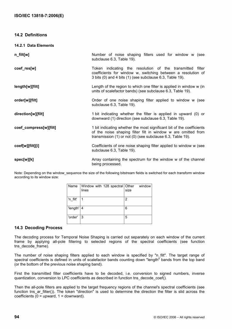
ISO/IEC 13818-7:2006(E)
94 © ISO/IEC 2006 – All rights reserved
14.2 Definitions
14.2.1 Data Elements
n_filt[w] Number of noise shaping filters used for window w (see subclause 6.3, Table 19).
coef_res[w] Token indicating the resolution of the transmitted filter coefficients for window w, switching between a resolution of 3 bits (0) and 4 bits (1) (see subclause 6.3, Table 19).
length[w][filt] Length of the region to which one filter is applied in window w (in units of scalefactor bands) (see subclause 6.3, Table 19).
order[w][filt] Order of one noise shaping filter applied to window w (see subclause 6.3, Table 19).
direction[w][filt] 1 bit indicating whether the filter is applied in upward (0) or downward (1) direction (see subclause 6.3, Table 19).
coef_compress[w][filt] 1 bit indicating whether the most significant bit of the coefficients of the noise shaping filter filt in window w are omitted from transmission (1) or not (0) (see subclause 6.3, Table 19).
coef[w][filt][i] Coefficients of one noise shaping filter applied to window w (see subclause 6.3, Table 19).
spec[w][k] Array containing the spectrum for the window w of the channel being processed.
Note: Depending on the window_sequence the size of the following bitstream fields is switched for each transform window according to its window size:
Name Window with 128 spectral lines
Other window size
'n_filt' 1 2
'length' 4 6
'order' 3 5
14.3 Decoding Process
The decoding process for Temporal Noise Shaping is carried out separately on each window of the current frame by applying all-pole filtering to selected regions of the spectral coefficients (see function tns_decode_frame).
The number of noise shaping filters applied to each window is specified by "n_filt". The target range of spectral coefficients is defined in units of scalefactor bands counting down "length" bands from the top band (or the bottom of the previous noise shaping band).
First the transmitted filter coefficients have to be decoded, i.e. conversion to signed numbers, inverse quantization, conversion to LPC coefficients as described in function tns_decode_coef().
Then the all-pole filters are applied to the target frequency regions of the channel's spectral coefficients (see function tns_ar_filter()). The token "direction" is used to determine the direction the filter is slid across the coefficients (0 = upward, 1 = downward).

ISO/IEC 13818-7:2006(E)
© ISO/IEC 2006 – All rights reserved 95
The constant TNS_MAX_BANDS defines the maximum number of scalefactor bands to which Temporal Noise Shaping is applied. The maximum possible filter order is defined by the constant TNS_MAX_ORDER. Both constants are profile dependent parameters.
The decoding process for one channel can be described as follows pseudo code:
/* TNS decoding for one channel and frame */ tns_decode_frame() { for (w = 0; w < num_windows; w++) { bottom = num_swb; for (f = 0; f < n_filt[w]; f++) { top = bottom; bottom = max(top - length[w][f], 0); tns_order = min(order[w][f], TNS_MAX_ORDER); if (!tns_order) continue; tns_decode_coef(tns_order, coef_res[w]+3, coef_compress[w][f], coef[w][f], lpc[]); start = swb_offset[min(bottom,TNS_MAX_BANDS,max_sfb)]; end = swb_offset[min(top,TNS_MAX_BANDS,max_sfb)]; if ((size = end - start) <= 0) continue; if (direction[w][f]) { inc = -1; start = end - 1; } else { inc = 1; } tns_ar_filter(&spec[w][start], size, inc, lpc[], tns_order); } } } Please note that this pseudo code uses a C-style interpretation of arrays and vectors, i.e. if coef[w][filt][i] describes the coefficients for all windows and filters, coef[w][filt] is a pointer to the coefficients of one particular window and filter. Also, the identifier coef is used as a formal parameter in function tns_decode_coef().
/* Decoder transmitted coefficients for one TNS filter */ tns_decode_coef(order, coef_res_bits, coef_compress, coef[], a[]) { /* Some internal tables */ sgn_mask[] = { 0x2, 0x4, 0x8 }; neg_mask[] = { ~0x3, ~0x7, ~0xf }; /* size used for transmission */ coef_res2 = coef_res_bits - coef_compress; s_mask = sgn_mask[coef_res2 - 2]; /* mask for sign bit */ n_mask = neg_mask[coef_res2 - 2]; /* mask for padding neg. values */ /* Conversion to signed integer */ for (i = 0; i < order; i++) tmp[i] = (coef[i] & s_mask) ? (coef[i] | n_mask) : coef[i]; /* Inverse quantization */ iqfac = ((1 << (coef_res_bits-1)) - 0.5) / (π/2.0); iqfac_m = ((1 << (coef_res_bits-1)) + 0.5) / (π/2.0); for (i = 0; i < order; i++) { tmp2[i] = sin(tmp[i] / ((tmp[i] >= 0) ? iqfac : iqfac_m)); } /* Conversion to LPC coefficients */ a[0] = 1; for (m = 1; m <= order; m++) { for (i = 1; i < m; i++) { b[i] = a[i] + tmp2[m-1] * a[m-i]; }

ISO/IEC 13818-7:2006(E)
96 © ISO/IEC 2006 – All rights reserved
for (i = 1; i < m; i++) { a[i] = b[i]; } a[m] = tmp2[m-1]; } } tns_ar_filter(spectrum[], size, inc, lpc[], order) { - Simple all-pole filter of order "order" defined by y(n) = x(n) - lpc[1]*y(n-1) - ... - lpc[order]*y(n-order) - The state variables of the filter are initialized to zero every time - The output data is written over the input data ("in-place operation") - An input vector of "size" samples is processed and the index increment to the next data sample is given by "inc" }
15 Filterbank and Block Switching
15.1 Tool Description
The time-frequency representation of the signal is mapped onto the time domain by feeding it into the filterbank module. This module consists of an inverse modified discrete cosine transform (IMDCT), and a window and an overlap-add function. In order to adapt the time/frequency resolution of the filterbank to the characteristics of the input signal, a block switching tool is also adopted. N represents the window length, where N is a function of the window_sequence, see subclause 8.3.3. For each channel, the N/2 time-frequency values Xi,k are transformed into the N time domain values xi,n via the IMDCT. After applying the window function, for each channel, the first half of the zi,n sequence is added to the second half of the previous block windowed sequence z(i-1),n to reconstruct the output samples for each channel outi,n.
15.2 Definitions
The syntax elements for the filterbank are specified in the raw data stream for the single_channel_element() (see subclause 6.3, Table 13), channel_pair_element() (see subclause 6.3, Table 14), and the coupling_channel (see subclause 6.3, Table 22). They consist of the control information window_sequence and window_shape.
15.2.1 Data Elements
window_sequence 2 bit indicating which window sequence (i.e. block size) is used (see subclause 6.3, Table 15).
window_shape 1 bit indicating which window function is selected (see subclause 6.3, Table 15).
Table 44 shows the four window_sequences (ONLY_LONG_SEQUENCE, LONG_START_SEQUENCE, EIGHT_SHORT_SEQUENCE, LONG_STOP_SEQUENCE).

ISO/IEC 13818-7:2006(E)
© ISO/IEC 2006 – All rights reserved 97
15.3 Decoding Process
15.3.1 IMDCT
The analytical expression of the IMDCT is:
( )∑−
=
⎟⎠
⎞⎜⎝
⎛⎟⎠⎞
⎜⎝⎛= ++
12
00, 2
12cos]][[
2N
kni knn
Nkispec
Nx π
for Nn <≤0
1)/2(N/2 = n
valuequence window_seon the basedlength window= N
indext coefficien spectral =k
index window= i
index sample =n
:where
0+
The synthesis window length N for the inverse transform is a function of the syntax element window_sequence and is defined as follows:
⎪⎪⎩
⎪⎪⎨
⎧
(0x3) SEQUENCELONG_STOP_ if 2048, times)(8 (0x2), T_SEQUENCEEIGHT_SHOR if 256,
(0x1) _SEQUENCELONG_START if 2048, (0x0) SEQUENCEONLY_LONG_ if 2048,
=N
The meaningful block transitions are as follows:
from ONLY_LONG_SEQUENCE to SEQUENCEONLY_LONG__SEQUENCELONG_START{
from LONG_START_SEQUENCE to T_SEQUENCEEIGHT_SHORSEQUENCELONG_STOP_{
from LONG_STOP_SEQUENCE to SEQUENCEONLY_LONG__SEQUENCELONG_START{
from EIGHT_SHORT_SEQUENCE to T_SEQUENCEEIGHT_SHORSEQUENCELONG_STOP_{
In addition to the meaningful block transitions the following transitions are possible:
from ONLY_LONG_SEQUENCE to T_SEQUENCEEIGHT_SHORSEQUENCELONG_STOP_{
from LONG_START_SEQUENCE to SEQUENCEONLY_LONG__SEQUENCELONG_START{
from LONG_STOP_SEQUENCE to T_SEQUENCEEIGHT_SHORSEQUENCELONG_STOP_{
from EIGHT_SHORT_SEQUENCE to SEQUENCEONLY_LONG__SEQUENCELONG_START{
This will still result in a reasonably smooth transition from one block to the next.

ISO/IEC 13818-7:2006(E)
98 © ISO/IEC 2006 – All rights reserved
15.3.2 Windowing and Block Switching
Depending on the window_sequence and window_shape element different transform windows are used. A combination of the window halves described as follows offers all possible window_sequences.
For window_shape == 1, the window coefficients are given by the Kaiser - Bessel derived (KBD) window as follows:
( )( )[ ]
( )[ ] 20for 2/
0
0
,'
,'
,_Nnn N
p
n
p
pW
pW
NLEFTKBDW <≤=
∑
∑
=
=
α
α
( )( )[ ]
( )[ ]NnNn N
p
nN
p
pW
pW
NRIGHTKBDW <≤=
∑
∑
=
−−
=
2for 2/
0
1
0
,'
,'
,_α
α
where:
W’ (Kaiser-Bessel kernel window function, see also Error! Reference source not found.) is defined as follows:
[ ]
4/
4/0.1I
= ),( '0
2
0
πα
πα
αI
N
Nn
nW⎥⎥⎦
⎤
⎢⎢⎣
⎡⎟⎠⎞
⎜⎝⎛ −
−
for 2
0N
n ≤≤
[ ]
⎩⎨⎧
⎥⎥⎥⎥
⎦
⎤
⎢⎢⎢⎢
⎣
⎡
∑∞
==
⎟⎟
⎠
⎞
⎜⎜
⎝
⎛
256 = Nfor 62048=Nfor 4
= factor, alpha windowkernel =
0
2
!2I 0
αα
k k
kx
x
Otherwise, for window_shape == 0, a sine window is employed as follows:
( )2
0for ))2
1(sin(
,_Nnn n
NNLEFTSINW <≤= +
π
( ) NnNn nNNRIGHTSIN
W <≤= +2
for ))2
1(sin(
,_π
The window length N can be 2048 or 256 for the KBD and the sine window. How to obtain the possible window sequences is explained in the parts a) - d) of this clause. All four window_sequences described below have a total length of 2048 samples.
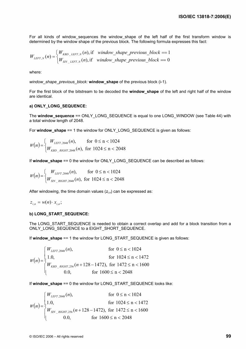
ISO/IEC 13818-7:2006(E)
© ISO/IEC 2006 – All rights reserved 99
For all kinds of window_sequences the window_shape of the left half of the first transform window is determined by the window shape of the previous block. The following formula expresses this fact:
⎩⎨⎧
====
=0 if ),(1 if ,)(
)(,_
,_, s_blockpe_previouwindow_shanW
s_blockpe_previouwindow_shanWnW
NLEFTSIN
NLEFTKBDNLEFT
where:
window_shape_previous_block: window_shape of the previous block (i-1).
For the first block of the bitstream to be decoded the window_shape of the left and right half of the window are identical.
a) ONLY_LONG_SEQUENCE:
The window_sequence == ONLY_LONG_SEQUENCE is equal to one LONG_WINDOW (see Table 44) with a total window length of 2048.
For window_shape == 1 the window for ONLY_LONG_SEQUENCE is given as follows:
( ) 2048n0241for ,)(
1024n0for ,)(
2048,_
2048,
⎩⎨⎧
<≤<≤
=nW
nWn
RIGHTKBD
LEFTW
If window_shape == 0 the window for ONLY_LONG_SEQUENCE can be described as follows:
( ) 0482n1024for ,)(
0241n0for ,)(
2048,_
2048,
⎩⎨⎧
<≤<≤
=nW
nWn
RIGHTSIN
LEFTW
After windowing, the time domain values (zi,n) can be expressed as:
;)( ,, nini xnwz ⋅=
b) LONG_START_SEQUENCE:
The LONG_START_SEQUENCE is needed to obtain a correct overlap and add for a block transition from a ONLY_LONG_SEQUENCE to a EIGHT_SHORT_SEQUENCE.
If window_shape == 1 the window for LONG_START_SEQUENCE is given as follows:
( )
⎪⎪⎩
⎪⎪⎨
⎧
<≤<≤−+<≤
<≤
=
2048n1600for ,0.01600n1472for ,)1472128(4721n1024for ,0.1
0241n0for ,)(
256,_
2048,
nW
nW
nRIGHTKBD
LEFT
W
If window_shape == 0 the window for LONG_START_SEQUENCE looks like:
( )
⎪⎪⎩
⎪⎪⎨
⎧
<≤<≤−+<≤
<≤
=
2048n1600for ,0.01600n1472for ,)1472128(
4721n1024for ,0.10241n0for ,)(
256,_
2048,
nW
nW
nRIGHTSIN
LEFT
W

ISO/IEC 13818-7:2006(E)
100 © ISO/IEC 2006 – All rights reserved
The windowed time-domain values can be calculated with the formula explained in a).
c) EIGHT_SHORT
The window_sequence == EIGHT_SHORT comprises eight overlapped and added SHORT_WINDOWs (see Table 44) with a length of 256 each. The total length of the window_sequence together with leading and following zeros is 2048. Each of the eight short blocks are windowed separately first. The short block number is indexed with the variable j = 0,…, 7.
The window_shape of the previous block influences the first of the eight short blocks (W0(n)) only.
If window_shape == 1 the window functions can be given as follows:
( ) 562n128for ,)(
128n0for ,)(
256,_
256,
0 ⎩⎨⎧
<≤<≤
=nW
nWn
RIGHTKBD
LEFTW
( ) 562n128for ),(
128n0for ,)(
256,_
256,_
71 ⎩⎨⎧
<≤<≤
=− nW
nWn
RIGHTKBD
LEFTKBDW
Otherwise, if window_shape == 0, the window functions can be described as:
( ) 562n128for ,)(
128n0for ,)(
256,_
256,
0 ⎩⎨⎧
<≤<≤
=nW
nWn
RIGHTSIN
LEFTW
( ) 562n128for ),(
128n0for ,)(
256,_
256,_
71 ⎩⎨⎧
<≤<≤
=− nW
nWn
RIGHTSIN
LEFTSINW
The overlap and add between the EIGHT_SHORT window_sequence resulting in the windowed time domain values zi,n is described as follows:
⎪⎪⎪⎪⎪⎪⎪
⎩
⎪⎪⎪⎪⎪⎪⎪
⎨
⎧
<≤
<≤−⋅
<≤−⋅+−⋅
<≤−⋅+−⋅
<≤−⋅+−⋅
<≤−⋅+−⋅<≤−⋅+−⋅<≤−⋅+−⋅
<≤−⋅+−⋅
<≤−⋅<≤
=
−
−−
−−
−−
−−
−−
−−
−−
−
2048n1600for ,01600n1472for ),1344(
1472n1344for ),1344()1216(1344n1216for ),1216()1088(
1216n1088for ),1088()960(1088n960for ),960()832(
960n832for ),832()704(832n704for ),704()576(704n576for ),576()448(
576n448for ),448( 448n0for ,0
71344,
71344,61216,
61216,51088,
51088,4960,
4960,3832,
3832,2704,
2704,1576,
1576,0448,
0448,
,
nWxnWxnWxnWxnWx
nWxnWxnWxnWx
nWxnWxnWxnWxnWxnWx
nWx
z
ni
nini
nini
nini
nini
nini
nini
nini
ni
ni
d) LONG_STOP_SEQUENCE
This window_sequence is needed to switch from a EIGHT_SHORT_SEQUENCE back to a ONLY_LONG_SEQUENCE.

ISO/IEC 13818-7:2006(E)
© ISO/IEC 2006 – All rights reserved 101
If window_shape == 1 the window for LONG_STOP_SEQUENCE is given as follows:
( )
⎪⎪⎩
⎪⎪⎨
⎧
<≤<≤<≤−
<≤
=
2048n1024for ,)(1024n576for ,0.1576n448for ,)448(
448n0for ,0.0
2048,_
256,
nW
nWn
RIGHTKBD
LEFTW
If window_shape == 0 the window for LONG_START_SEQUENCE is determined by:
( )
⎪⎪⎩
⎪⎪⎨
⎧
<≤<≤<≤−
<≤
=
2048n1024for ,)(1024n576for ,0.1576n448for ,)448(
448n0for ,0.0
2048,_
256,
nW
nWn
RIGHTSIN
LEFTW
The windowed time domain values can be calculated with the formula explained in a).
15.3.3 Overlapping and Adding with Previous Window Sequence
Besides the overlap and add within the EIGHT_SHORT window_sequence the first (left) half of every window_sequence is overlapped and added with the second (right) half of the previous window_sequence resulting in the final time domain values outi,n. The mathematic expression for this operation can be described as follows. It is valid for all four possible window_sequences.
2048N ,2Nn0for ;
2,1,, =<≤+=+−
Nninini zzout
16 Gain Control
16.1 Tool Description
The gain control tool is made up of several gain compensators and overlap/add processing stages, and an IPQF (Inverse Polyphase Quadrature Filter) stage. This tool receives non-overlapped signal sequences provided by the IMDCT stages, window_sequence and gain_control_data, and then reproduces the output PCM data. The block diagram for the gain control tool is shown in Figure 9.
Due to the characteristics of the PQF filterbank, the order of the MDCT coefficients in each even PQF band must be reversed. This is done by reversing the spectral order of the MDCT coefficients, i.e. exchanging the higher frequency MDCT coefficients with the lower frequency MDCT coefficients.
If the gain control tool is used, the configuration of the filter bank tool is changed as follows. In the case of an EIGHT_SHORT_SEQUENCE window_sequence, the number of coefficients for the IMDCT is 32 instead of 128 and eight IMDCTs are carried out. In the case of other window_sequence values, the number of coefficients for the IMDCT is 256 instead of 1024 and one IMDCT is performed. In all cases, the filter bank tool outputs a total of 2048 non-overlapped values per frame. These values are supplied to the gain control tool as ( )jU BW , defined in 16.3.3.
The IPQF combines four uniform frequency bands and produces a decoded time domain output signal. The aliasing components introduced by the PQF in the encoder are cancelled by the IPQF.
The gain values for each band can be controlled independently except for the lowest frequency band. The step size of gain control is 2 ^ n where n is an integer.
The gain control tool outputs a time signal sequence which is ( )nAS defined in 16.3.4.

ISO/IEC 13818-7:2006(E)
102 © ISO/IEC 2006 – All rights reserved
16.2 Definitions
16.2.1 Data Elements
adjust_num 3-bit field indicating the number of gain changes for each IPQF band. The maximum number of gain changes is seven (see subclause 6.3, Table 27).
max_band 2-bit field indicating the number of IPQF bands in which their signal gain have been controlled.
The meanings of this value are shown below (see subclause 6.3, Table 27).
0: no bands have activated gain control.
1: signal gain on 2nd IPQF band has been controlled.
2: signal gain on 2nd and 3rd IPQF bands have been controlled.
3: signal gain on 2nd, 3rd and 4th IPQF bands have been controlled.
alevcode 4-bit field indicating the gain value for one gain change (see subclause 6.3, Table 27).
aloccode 2-, 4-, or 5-bit field indicating the position for one gain change. The length of this data varies depending on the window sequence (see subclause 6.3, Table 27).
16.2.2 Help Elements
gain control data side information indicating the gain values and the positions used for the gain change.
IPQF band each split band of IPQF.
16.3 Decoding Process
The following four processes are required for decoding.
(1) Gain control data decoding
(2) Gain control function setting
(3) Gain control windowing and overlapping
(4) Synthesis filter
16.3.1 Gain Control Data Decoding
Gain control data are reconstructed as follows.
(1)
[ ][ ]WBNAD BW adjust_num, =

ISO/IEC 13818-7:2006(E)
© ISO/IEC 2006 – All rights reserved 103
(2)
( ) [ ][ ][ ]( ) BWBW NADmmWBAdjLocmALOC ,, 1,1aloccode ≤≤−=
( ) [ ][ ][ ]( )BW
mWBAdjLevBW NADmmALEV ,
1alevcode, 1,2 ≤≤= −
(3)
( ) 00, =BWALOC
( ) ( )⎩⎨⎧ ==
=otherwiseALEV
NADifALEV
BW
BWBW ,1
0,10
,
,,
(4)
( )
⎪⎪⎪⎪⎪
⎩
⎪⎪⎪⎪⎪
⎨
⎧
⎭⎬⎫
====≤≤
⎭⎬⎫
======
=+
SEQUENCELONG_STOP_1,2560,112
T_SEQUENCEEIGHT_SHOR70,32
_SEQUENCELONG_START1,32
0,112SEQUENCEONLY_LONG_0,256
1,,
ifWW
ifW
ifWW
ifW
NADALOC BWBW
( ) 11,, =+BWBW NADALEV
where
BWNAD , : Gain Control Information Number, an integer
( )mALOC BW , : Gain Control Location, an integer
( )mALEV BW , : Gain Control Level, an integer-valued real number
B: Band ID, an integer from 1 to 3
W: Window ID, an integer from 0 to 7
m: an integer
aloccode[B][W][m] must be set so that ( ){ }mALOC BW , satisfies the following conditions.
( ) ( ) 11, ,212,1, +≤<≤< BWBWBW NADmmmALOCmALOC
In cases of LONG_START_SEQUENCE and LONG_STOP_SEQUENCE, the values 14 and 15 of aloccode[B][0][m] are invalid. AdjLoc() is defined in Table 64. AdjLev() is defined in Table 65.
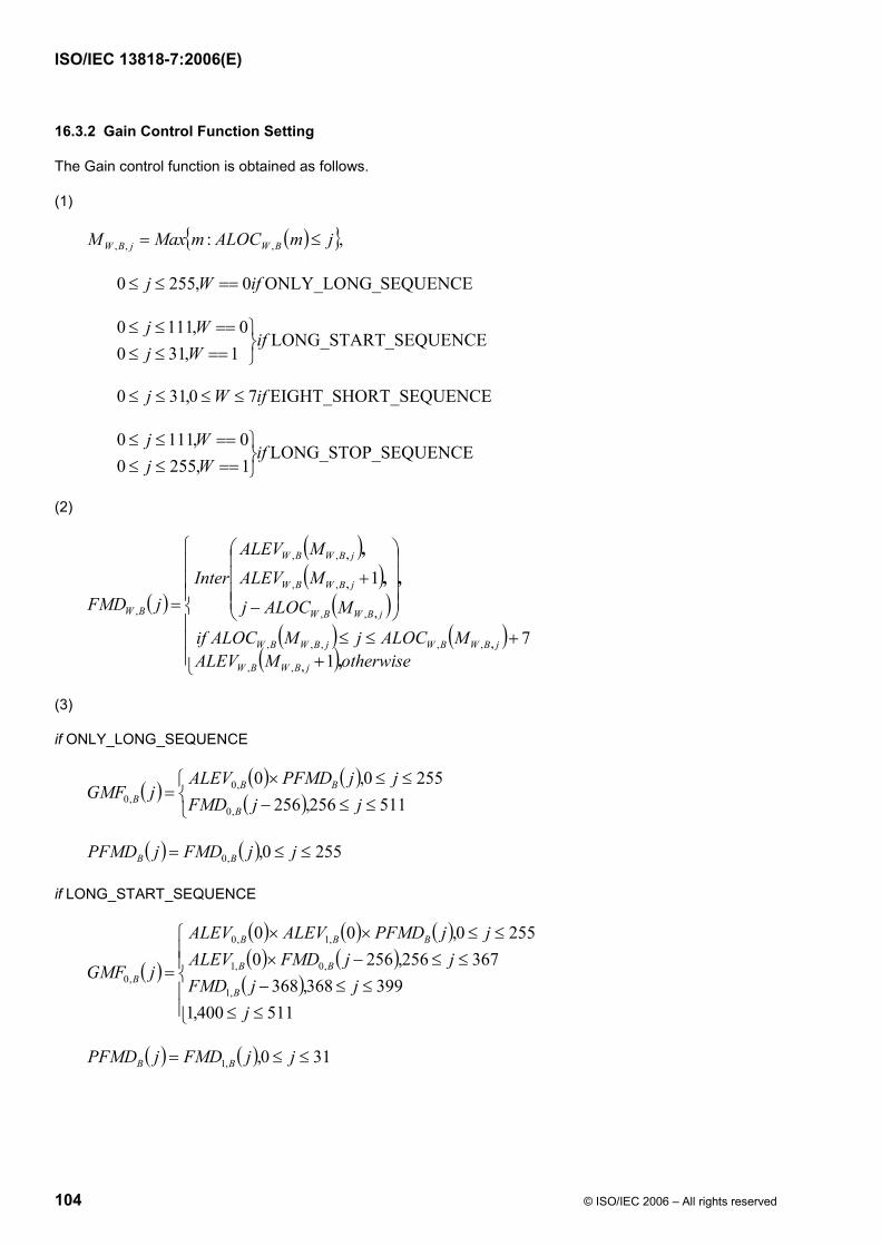
ISO/IEC 13818-7:2006(E)
104 © ISO/IEC 2006 – All rights reserved
16.3.2 Gain Control Function Setting
The Gain control function is obtained as follows.
(1)
( ){ },: ,,, jmALOCmMaxM BWjBW ≤=
SEQUENCEONLY_LONG_0,2550 ifWj ==≤≤
_SEQUENCELONG_START1,310
0,1110if
WjWj
⎭⎬⎫
==≤≤==≤≤
T_SEQUENCEEIGHT_SHOR70,310 ifWj ≤≤≤≤
SEQUENCELONG_STOP_1,25500,1110
ifWjWj
⎭⎬⎫
==≤≤==≤≤
(2)
( )
( )( )
( )( ) ( )
( )⎪⎪⎪
⎩
⎪⎪⎪
⎨
⎧
++≤≤
⎟⎟⎟⎟
⎠
⎞
⎜⎜⎜⎜
⎝
⎛
−
+=
otherwiseMALEVMALOCjMALOCif
MALOCj
MALEVMALEV
InterjFMD
jBWBW
jBWBWjBWBW
jBWBW
jBWBW
jBWBW
BW
,
,,,
,
,
,
,
,
17
1
,,
,,,,,
,,
,,
,,
,
(3)
if ONLY_LONG_SEQUENCE
( ) ( ) ( )( )⎩
⎨⎧
≤≤−≤≤×
=511256,256
2550,0
,0
,0,0 jjFMD
jjPFMDALEVjGMF
B
BBB
( ) ( ) 2550,,0 ≤≤= jjFMDjPFMD BB
if LONG_START_SEQUENCE
( )
( ) ( ) ( )( ) ( )( )
⎪⎪⎩
⎪⎪⎨
⎧
≤≤≤≤−
≤≤−×≤≤××
=
511400,1399368,368
367256,25602550,00
,1
,0,1
,1,0
,0
jjjFMD
jjFMDALEVjjPFMDALEVALEV
jGMFB
BB
BBB
B
( ) ( ) 310,,1 ≤≤= jjFMDjPFMD BB
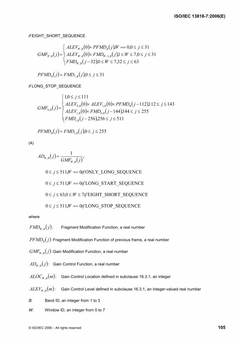
ISO/IEC 13818-7:2006(E)
© ISO/IEC 2006 – All rights reserved 105
if EIGHT_SHORT_SEQUENCE
( )( ) ( )( ) ( )( )⎪
⎩
⎪⎨
⎧
≤≤≤≤−≤≤≤≤×
≤≤==×= −
6332,70,32310,71,0
310,0,0
,
,1,
,
,
jWjFMDjWjFMDALEV
jWjPFMDALEVjGMF
BW
BWBW
BBW
BW
( ) ( ) 310,,7 ≤≤= jjFMDjPFMD BB
if LONG_STOP_SEQUENCE
( ) ( ) ( ) ( )( ) ( )( )⎪
⎪⎩
⎪⎪⎨
⎧
≤≤−≤≤−×
≤≤−××≤≤
=
511256,256255144,1440
143112,112001110,1
,1
,0,1
,1,0,0
jjFMDjjFMDALEV
jjPFMDALEVALEVj
jGMF
B
BB
BBBB
( ) ( ) 2550,,1 ≤≤= jjFMDjPFMD BB
(4)
( ) ( ) ,1
,, jGMF
jADBW
BW =
SEQUENCEONLY_LONG_0,5110 ifWj ==≤≤
_SEQUENCELONG_START0,5110 ifWj ==≤≤
T_SEQUENCEEIGHT_SHOR70,630 ifWj ≤≤≤≤
SEQUENCELONG_STOP_0,5110 ifWj ==≤≤
where
( )jFMD BW , : Fragment Modification Function, a real number
( )jPFMDB : Fragment Modification Function of previous frame, a real number
( )jGMF BW , : Gain Modification Function, a real number
( )jAD BW , : Gain Control Function, a real number
( )mALOC BW , : Gain Control Location defined in subclause 16.3.1, an integer
( )mALEV BW , : Gain Control Level defined in subclause 16.3.1, an integer-valued real number
B: Band ID, an integer from 1 to 3
W: Window ID, an integer from 0 to 7

ISO/IEC 13818-7:2006(E)
106 © ISO/IEC 2006 – All rights reserved
jBWM ,, : an integer
m: an integer
and
( )( ) ( ) ( )
8loglog8 22
2,,bjaj
jbaInter+−
=
Note that the initial value of ( )jPFMDB must be set 1.0.
16.3.3 Gain Control Windowing and Overlapping
Band Sample Data are obtained through the processes (1) to (2) shown below.
(1) Gain Control Windowing
if B = 0
( ) ( ),,, jUjT BWBW =
SEQUENCEONLY_LONG_0,5110 ifWj ==≤≤
_SEQUENCELONG_START0,5110 ifWj ==≤≤
T_SEQUENCEEIGHT_SHOR70,630 ifWj ≤≤≤≤
SEQUENCELONG_STOP_0,5110 ifWj ==≤≤
else
( ) ( ) ( ),,,, jUjADjT BWBWBW ×=
SEQUENCEONLY_LONG_0,5110 ifWj ==≤≤
_SEQUENCELONG_START0,5110 ifWj ==≤≤
T_SEQUENCEEIGHT_SHOR70,630 ifWj ≤≤≤≤
SEQUENCELONG_STOP_0,5110 ifWj ==≤≤
(2) Overlapping
if ONLY_LONG_SEQUENCE
( ) ( ) ( ) 2550,,0 ≤≤+= jjTjPTjV BBB
( ) ( ) 2550,256,0 ≤≤+= jjTjPT BB
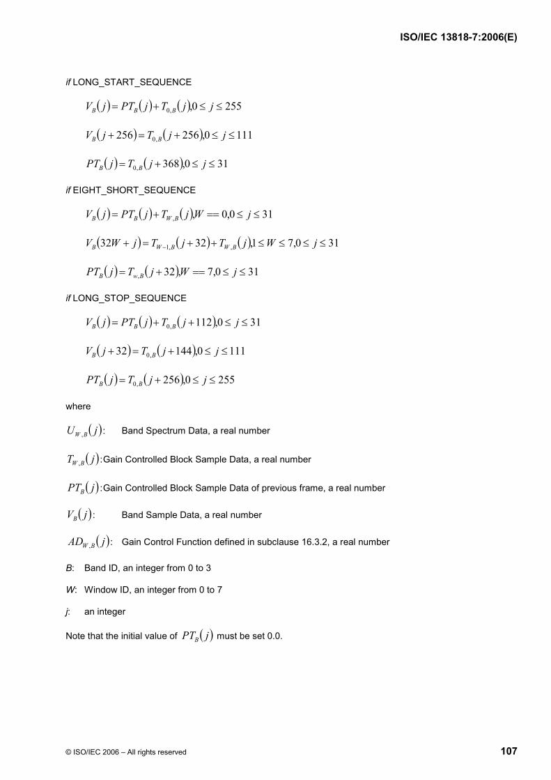
ISO/IEC 13818-7:2006(E)
© ISO/IEC 2006 – All rights reserved 107
if LONG_START_SEQUENCE
( ) ( ) ( ) 2550,,0 ≤≤+= jjTjPTjV BBB
( ) ( ) 1110,256256 ,0 ≤≤+=+ jjTjV BB
( ) ( ) 310,368,0 ≤≤+= jjTjPT BB
if EIGHT_SHORT_SEQUENCE
( ) ( ) ( ) 310,0,, ≤≤==+= jWjTjPTjV BWBB
( ) ( ) ( ) 310,71,3232 ,,1 ≤≤≤≤++=+ − jWjTjTjWV BWBWB
( ) ( ) 310,7,32, ≤≤==+= jWjTjPT BwB
if LONG_STOP_SEQUENCE
( ) ( ) ( ) 310,112,0 ≤≤++= jjTjPTjV BBB
( ) ( ) 1110,14432 ,0 ≤≤+=+ jjTjV BB
( ) ( ) 2550,256,0 ≤≤+= jjTjPT BB
where
( )jU BW , : Band Spectrum Data, a real number
( )jT BW , : Gain Controlled Block Sample Data, a real number
( )jPTB : Gain Controlled Block Sample Data of previous frame, a real number
( )jVB : Band Sample Data, a real number
( )jAD BW , : Gain Control Function defined in subclause 16.3.2, a real number
B: Band ID, an integer from 0 to 3
W: Window ID, an integer from 0 to 7
j: an integer
Note that the initial value of ( )jPTB must be set 0.0.

ISO/IEC 13818-7:2006(E)
108 © ISO/IEC 2006 – All rights reserved
16.3.4 Synthesis Filter
Audio Sample Data are obtained from the following equations.
(1)
( ) ( )⎩⎨⎧
≤≤==
= 30,0
,4,~ Belse
kjifkVjV B
B
(2)
( ) ( ) ( )( ) 30,950,16
3212cos ≤≤≤≤⎟⎠⎞
⎜⎝⎛ −+
×= BjjBjQjQBπ
(3)
( ) ( ) ( )∑∑= =
−×=3
0
95
0
~B j
BB jnVjQnAS
where
( )nAS : Audio Sample Data
( )nVB : Band Sample Data defined in subclause 16.3.3, a real number
( )jVB~
: Interpolated Band Sample Data, a real number
( )jQB : Synthesis Filter Coefficients, a real number
( )jQ : Prototype Coefficients given below, a real number
B: Band ID, an integer from 0 to 3
W: Window ID, an integer from 0 to 7
n: an integer
j: an integer
k: an integer
The values of Q(0) to Q(47) are shown in Table 66. The values of Q(48) to Q(95) are obtained from the following equation.
( ) ( ) 9548,95 ≤≤−= jjQjQ
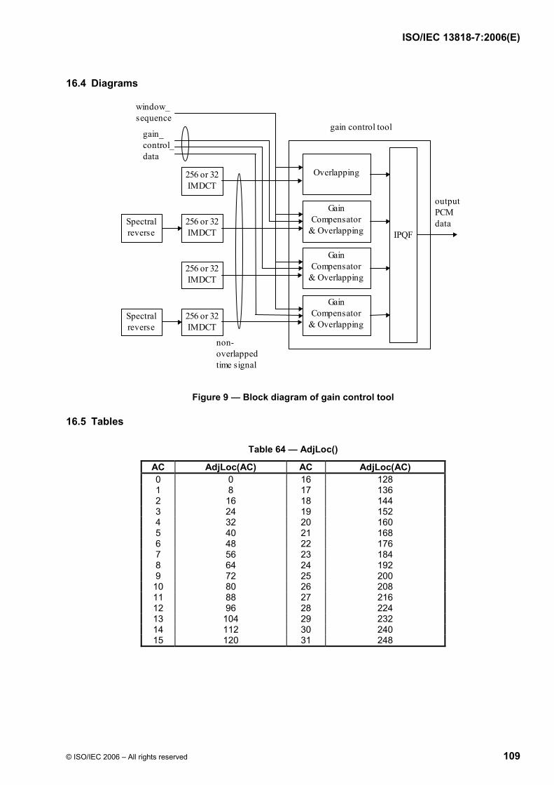
ISO/IEC 13818-7:2006(E)
© ISO/IEC 2006 – All rights reserved 109
16.4 Diagrams
IPQF
Overlapping
gain_control_data
gain control tool
GainCompensator
& Overlapping
GainCompensator
& Overlapping
GainCompensator
& Overlapping
window_sequence
non-overlappedtime signal
outputPCMdata
256 or 32IMDCT
256 or 32IMDCT
256 or 32IMDCT
256 or 32IMDCT
Spectralreverse
Spectralreverse
Figure 9 — Block diagram of gain control tool
16.5 Tables
Table 64 — AdjLoc()
AC AdjLoc(AC) AC AdjLoc(AC) 0 0 16 128 1 8 17 136 2 16 18 144 3 24 19 152 4 32 20 160 5 40 21 168 6 48 22 176 7 56 23 184 8 64 24 192 9 72 25 200 10 80 26 208 11 88 27 216 12 96 28 224 13 104 29 232 14 112 30 240 15 120 31 248

ISO/IEC 13818-7:2006(E)
110 © ISO/IEC 2006 – All rights reserved
Table 65 — AdjLev()
AV AdjLev(AV) 0 -4 1 -3 2 -2 3 -1 4 0 5 1 6 2 7 3 8 4 9 5 10 6 11 7 12 8 13 9 14 10 15 11
Table 66 — Q()
j Q(j) j Q(j) 0 9.7655291007575512E-05 24 -2.2656858741499447E-02 1 1.3809589379038567E-04 25 -6.8031113858963354E-03 2 9.8400749256623534E-05 26 1.5085400948280744E-02 3 -8.6671544782335723E-05 27 3.9750993388272739E-02 4 -4.6217998911921346E-04 28 6.2445363629436743E-02 5 -1.0211814095158174E-03 29 7.7622327748721326E-02 6 -1.6772149340010668E-03 30 7.9968338496132926E-02 7 -2.2533338951411081E-03 31 6.5615493068475583E-02 8 -2.4987888343213967E-03 32 3.3313658300882690E-02 9 -2.1390815966761882E-03 33 -1.4691563058190206E-02 10 -9.5595397454597772E-04 34 -7.2307890475334147E-02 11 1.1172111530118943E-03 35 -1.2993222541703875E-01 12 3.9091309127348584E-03 36 -1.7551641029040532E-01 13 6.9635703420118673E-03 37 -1.9626543957670528E-01 14 9.5595442159478339E-03 38 -1.8073330670215029E-01 15 1.0815766540021360E-02 39 -1.2097653136035738E-01 16 9.8770514991715300E-03 40 -1.4377370758549035E-02 17 6.1562567291327357E-03 41 1.3522730742860303E-01 18 -4.1793946063629710E-04 42 3.1737852699301633E-01 19 -9.2128743097707640E-03 43 5.1590021798482233E-01 20 -1.8830775873369020E-02 44 7.1080020379761377E-01 21 -2.7226498457701823E-02 45 8.8090632488444798E-01 22 -3.2022840857588906E-02 46 1.0068321641150089E+00 23 -3.0996332527754609E-02 47 1.0737914947736096E+00

ISO/IEC 13818-7:2006(E)
© ISO/IEC 2006 – All rights reserved 111
Annex A (normative)
Huffman Codebook Tables
Table A.1 — Scalefactor Huffman Codebook
index length codeword (hexadecimal)
index length codeword (hexadecimal)
0 18 3ffe8 61 4 a 1 18 3ffe6 62 4 c 2 18 3ffe7 63 5 1b 3 18 3ffe5 64 6 39 4 19 7fff5 65 6 3b 5 19 7fff1 66 7 78 6 19 7ffed 67 7 7a 7 19 7fff6 68 8 f7 8 19 7ffee 69 8 f9 9 19 7ffef 70 9 1f6 10 19 7fff0 71 9 1f9 11 19 7fffc 72 10 3f4 12 19 7fffd 73 10 3f6 13 19 7ffff 74 10 3f8 14 19 7fffe 75 11 7f5 15 19 7fff7 76 11 7f4 16 19 7fff8 77 11 7f6 17 19 7fffb 78 11 7f7 18 19 7fff9 79 12 ff5 19 18 3ffe4 80 12 ff8 20 19 7fffa 81 13 1ff4 21 18 3ffe3 82 13 1ff6 22 17 1ffef 83 13 1ff8 23 17 1fff0 84 14 3ff8 24 16 fff5 85 14 3ff4 25 17 1ffee 86 16 fff0 26 16 fff2 87 15 7ff4 27 16 fff3 88 16 fff6 28 16 fff4 89 15 7ff5 29 16 fff1 90 18 3ffe2 30 15 7ff6 91 19 7ffd9 31 15 7ff7 92 19 7ffda 32 14 3ff9 93 19 7ffdb 33 14 3ff5 94 19 7ffdc 34 14 3ff7 95 19 7ffdd 35 14 3ff3 96 19 7ffde 36 14 3ff6 97 19 7ffd8 37 14 3ff2 98 19 7ffd2 38 13 1ff7 99 19 7ffd3 39 13 1ff5 100 19 7ffd4 40 12 ff9 101 19 7ffd5 41 12 ff7 102 19 7ffd6 42 12 ff6 103 19 7fff2 43 11 7f9 104 19 7ffdf

ISO/IEC 13818-7:2006(E)
112 © ISO/IEC 2006 – All rights reserved
44 12 ff4 105 19 7ffe7 45 11 7f8 106 19 7ffe8 46 10 3f9 107 19 7ffe9 47 10 3f7 108 19 7ffea 48 10 3f5 109 19 7ffeb 49 9 1f8 110 19 7ffe6 50 9 1f7 111 19 7ffe0 51 8 fa 112 19 7ffe1 52 8 f8 113 19 7ffe2 53 8 f6 114 19 7ffe3 54 7 79 115 19 7ffe4 55 6 3a 116 19 7ffe5 56 6 38 117 19 7ffd7 57 5 1a 118 19 7ffec 58 4 b 119 19 7fff4 59 3 4 120 19 7fff3 60 1 0
Table A.2 — Spectrum Huffman Codebook 1
index length codeword (hexadecimal)
index length codeword (hexadecimal)
0 11 7f8 41 5 14 1 9 1f1 42 7 65 2 11 7fd 43 5 16 3 10 3f5 44 7 6d 4 7 68 45 9 1e9 5 10 3f0 46 7 63 6 11 7f7 47 9 1e4 7 9 1ec 48 7 6b 8 11 7f5 49 5 13 9 10 3f1 50 7 71 10 7 72 51 9 1e3 11 10 3f4 52 7 70 12 7 74 53 9 1f3 13 5 11 54 11 7fe 14 7 76 55 9 1e7 15 9 1eb 56 11 7f3 16 7 6c 57 9 1ef 17 10 3f6 58 7 60 18 11 7fc 59 9 1ee 19 9 1e1 60 11 7f0 20 11 7f1 61 9 1e2 21 9 1f0 62 11 7fa 22 7 61 63 10 3f3 23 9 1f6 64 7 6a 24 11 7f2 65 9 1e8 25 9 1ea 66 7 75 26 11 7fb 67 5 10 27 9 1f2 68 7 73 28 7 69 69 9 1f4 29 9 1ed 70 7 6e 30 7 77 71 10 3f7 31 5 17 72 11 7f6 32 7 6f 73 9 1e0

ISO/IEC 13818-7:2006(E)
© ISO/IEC 2006 – All rights reserved 113
33 9 1e6 74 11 7f9 34 7 64 75 10 3f2 35 9 1e5 76 7 66 36 7 67 77 9 1f5 37 5 15 78 11 7ff 38 7 62 79 9 1f7 39 5 12 80 11 7f4 40 1 0
Table A.3 — Spectrum Huffman Codebook 2
index length codeword (hexadecimal)
index length codeword (hexadecimal)
0 9 1f3 41 5 7 1 7 6f 42 6 1d 2 9 1fd 43 5 b 3 8 eb 44 6 30 4 6 23 45 8 ef 5 8 ea 46 6 1c 6 9 1f7 47 7 64 7 8 e8 48 6 1e 8 9 1fa 49 5 c 9 8 f2 50 6 29 10 6 2d 51 8 f3 11 7 70 52 6 2f 12 6 20 53 8 f0 13 5 6 54 9 1fc 14 6 2b 55 7 71 15 7 6e 56 9 1f2 16 6 28 57 8 f4 17 8 e9 58 6 21 18 9 1f9 59 8 e6 19 7 66 60 8 f7 20 8 f8 61 7 68 21 8 e7 62 9 1f8 22 6 1b 63 8 ee 23 8 f1 64 6 22 24 9 1f4 65 7 65 25 7 6b 66 6 31 26 9 1f5 67 4 2 27 8 ec 68 6 26 28 6 2a 69 8 ed 29 7 6c 70 6 25 30 6 2c 71 7 6a 31 5 a 72 9 1fb 32 6 27 73 7 72 33 7 67 74 9 1fe 34 6 1a 75 7 69 35 8 f5 76 6 2e 36 6 24 77 8 f6 37 5 8 78 9 1ff 38 6 1f 79 7 6d 39 5 9 80 9 1f6 40 3 0

ISO/IEC 13818-7:2006(E)
114 © ISO/IEC 2006 – All rights reserved
Table A.4 — Spectrum Huffman Codebook 3
index length codeword (hexadecimal)
index length codeword (hexadecimal)
0 1 0 41 10 3ef 1 4 9 42 9 1f3 2 8 ef 43 9 1f4 3 4 b 44 11 7f6 4 5 19 45 9 1e8 5 8 f0 46 10 3ea 6 9 1eb 47 13 1ffc 7 9 1e6 48 8 f2 8 10 3f2 49 9 1f1 9 4 a 50 12 ffb 10 6 35 51 10 3f5 11 9 1ef 52 11 7f3 12 6 34 53 12 ffc 13 6 37 54 8 ee 14 9 1e9 55 10 3f7 15 9 1ed 56 15 7ffe 16 9 1e7 57 9 1f0 17 10 3f3 58 11 7f5 18 9 1ee 59 15 7ffd 19 10 3ed 60 13 1ffb 20 13 1ffa 61 14 3ffa 21 9 1ec 62 16 ffff 22 9 1f2 63 8 f1 23 11 7f9 64 10 3f0 24 11 7f8 65 14 3ffc 25 10 3f8 66 9 1ea 26 12 ff8 67 10 3ee 27 4 8 68 14 3ffb 28 6 38 69 12 ff6 29 10 3f6 70 12 ffa 30 6 36 71 15 7ffc 31 7 75 72 11 7f2 32 10 3f1 73 12 ff5 33 10 3eb 74 16 fffe 34 10 3ec 75 10 3f4 35 12 ff4 76 11 7f7 36 5 18 77 15 7ffb 37 7 76 78 12 ff7 38 11 7f4 79 12 ff9 39 6 39 80 15 7ffa 40 7 74

ISO/IEC 13818-7:2006(E)
© ISO/IEC 2006 – All rights reserved 115
Table A.5 — Spectrum Huffman Codebook 4
index length codeword (hexadecimal)
index length codeword (hexadecimal)
0 4 7 41 7 6b 1 5 16 42 8 e3 2 8 f6 43 7 69 3 5 18 44 9 1f3 4 4 8 45 8 eb 5 8 ef 46 8 e6 6 9 1ef 47 10 3f6 7 8 f3 48 7 6e 8 11 7f8 49 7 6a 9 5 19 50 9 1f4 10 5 17 51 10 3ec 11 8 ed 52 9 1f0 12 5 15 53 10 3f9 13 4 1 54 8 f5 14 8 e2 55 8 ec 15 8 f0 56 11 7fb 16 7 70 57 8 ea 17 10 3f0 58 7 6f 18 9 1ee 59 10 3f7 19 8 f1 60 11 7f9 20 11 7fa 61 10 3f3 21 8 ee 62 12 fff 22 8 e4 63 8 e9 23 10 3f2 64 7 6d 24 11 7f6 65 10 3f8 25 10 3ef 66 7 6c 26 11 7fd 67 7 68 27 4 5 68 9 1f5 28 5 14 69 10 3ee 29 8 f2 70 9 1f2 30 4 9 71 11 7f4 31 4 4 72 11 7f7 32 8 e5 73 10 3f1 33 8 f4 74 12 ffe 34 8 e8 75 10 3ed 35 10 3f4 76 9 1f1 36 4 6 77 11 7f5 37 4 2 78 11 7fe 38 8 e7 79 10 3f5 39 4 3 80 11 7fc 40 4 0

ISO/IEC 13818-7:2006(E)
116 © ISO/IEC 2006 – All rights reserved
Table A.6 — Spectrum Huffman Codebook 5
index length codeword (hexadecimal)
index length codeword (hexadecimal)
0 13 1fff 41 4 a 1 12 ff7 42 7 71 2 11 7f4 43 8 f3 3 11 7e8 44 11 7e9 4 10 3f1 45 11 7ef 5 11 7ee 46 9 1ee 6 11 7f9 47 8 ef 7 12 ff8 48 5 18 8 13 1ffd 49 4 9 9 12 ffd 50 5 1b 10 11 7f1 51 8 eb 11 10 3e8 52 9 1e9 12 9 1e8 53 11 7ec 13 8 f0 54 11 7f6 14 9 1ec 55 10 3eb 15 10 3ee 56 9 1f3 16 11 7f2 57 8 ed 17 12 ffa 58 7 72 18 12 ff4 59 8 e9 19 10 3ef 60 9 1f1 20 9 1f2 61 10 3ed 21 8 e8 62 11 7f7 22 7 70 63 12 ff6 23 8 ec 64 11 7f0 24 9 1f0 65 10 3e9 25 10 3ea 66 9 1ed 26 11 7f3 67 8 f1 27 11 7eb 68 9 1ea 28 9 1eb 69 10 3ec 29 8 ea 70 11 7f8 30 5 1a 71 12 ff9 31 4 8 72 13 1ffc 32 5 19 73 12 ffc 33 8 ee 74 12 ff5 34 9 1ef 75 11 7ea 35 11 7ed 76 10 3f3 36 10 3f0 77 10 3f2 37 8 f2 78 11 7f5 38 7 73 79 12 ffb 39 4 b 80 13 1ffe 40 1 0

ISO/IEC 13818-7:2006(E)
© ISO/IEC 2006 – All rights reserved 117
Table A.7 — Spectrum Huffman Codebook 6
index length codeword (hexadecimal)
index length codeword (hexadecimal)
0 11 7fe 41 4 3 1 10 3fd 42 6 2f 2 9 1f1 43 7 73 3 9 1eb 44 9 1fa 4 9 1f4 45 9 1e7 5 9 1ea 46 7 6e 6 9 1f0 47 6 2b 7 10 3fc 48 4 7 8 11 7fd 49 4 1 9 10 3f6 50 4 5 10 9 1e5 51 6 2c 11 8 ea 52 7 6d 12 7 6c 53 9 1ec 13 7 71 54 9 1f9 14 7 68 55 8 ee 15 8 f0 56 6 30 16 9 1e6 57 6 24 17 10 3f7 58 6 2a 18 9 1f3 59 6 25 19 8 ef 60 6 33 20 6 32 61 8 ec 21 6 27 62 9 1f2 22 6 28 63 10 3f8 23 6 26 64 9 1e4 24 6 31 65 8 ed 25 8 eb 66 7 6a 26 9 1f7 67 7 70 27 9 1e8 68 7 69 28 7 6f 69 7 74 29 6 2e 70 8 f1 30 4 8 71 10 3fa 31 4 4 72 11 7ff 32 4 6 73 10 3f9 33 6 29 74 9 1f6 34 7 6b 75 9 1ed 35 9 1ee 76 9 1f8 36 9 1ef 77 9 1e9 37 7 72 78 9 1f5 38 6 2d 79 10 3fb 39 4 2 80 11 7fc 40 4 0
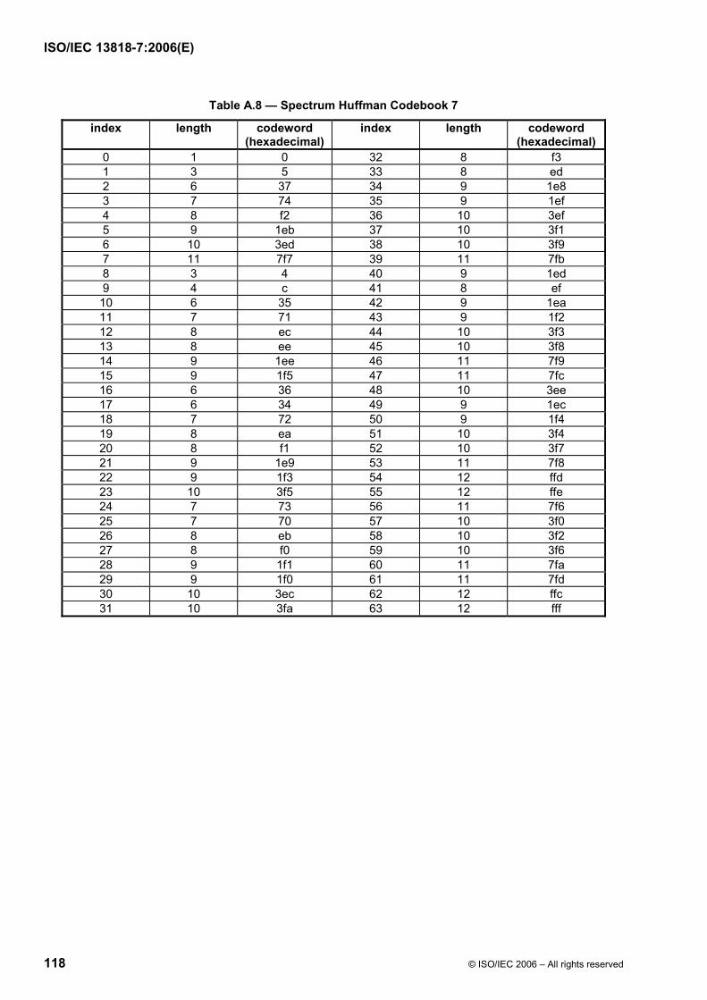
ISO/IEC 13818-7:2006(E)
118 © ISO/IEC 2006 – All rights reserved
Table A.8 — Spectrum Huffman Codebook 7
index length codeword (hexadecimal)
index length codeword (hexadecimal)
0 1 0 32 8 f3 1 3 5 33 8 ed 2 6 37 34 9 1e8 3 7 74 35 9 1ef 4 8 f2 36 10 3ef 5 9 1eb 37 10 3f1 6 10 3ed 38 10 3f9 7 11 7f7 39 11 7fb 8 3 4 40 9 1ed 9 4 c 41 8 ef 10 6 35 42 9 1ea 11 7 71 43 9 1f2 12 8 ec 44 10 3f3 13 8 ee 45 10 3f8 14 9 1ee 46 11 7f9 15 9 1f5 47 11 7fc 16 6 36 48 10 3ee 17 6 34 49 9 1ec 18 7 72 50 9 1f4 19 8 ea 51 10 3f4 20 8 f1 52 10 3f7 21 9 1e9 53 11 7f8 22 9 1f3 54 12 ffd 23 10 3f5 55 12 ffe 24 7 73 56 11 7f6 25 7 70 57 10 3f0 26 8 eb 58 10 3f2 27 8 f0 59 10 3f6 28 9 1f1 60 11 7fa 29 9 1f0 61 11 7fd 30 10 3ec 62 12 ffc 31 10 3fa 63 12 fff

ISO/IEC 13818-7:2006(E)
© ISO/IEC 2006 – All rights reserved 119
Table A.9 — Spectrum Huffman Codebook 8
index length codeword (hexadecimal)
index length codeword (hexadecimal)
0 5 e 32 7 71 1 4 5 33 6 2b 2 5 10 34 6 2d 3 6 30 35 6 31 4 7 6f 36 7 6d 5 8 f1 37 7 70 6 9 1fa 38 8 f2 7 10 3fe 39 9 1f9 8 4 3 40 8 ef 9 3 0 41 7 68 10 4 4 42 6 33 11 5 12 43 7 6b 12 6 2c 44 7 6e 13 7 6a 45 8 ee 14 7 75 46 8 f9 15 8 f8 47 10 3fc 16 5 f 48 9 1f8 17 4 2 49 7 74 18 4 6 50 7 73 19 5 14 51 8 ed 20 6 2e 52 8 f0 21 7 69 53 8 f6 22 7 72 54 9 1f6 23 8 f5 55 9 1fd 24 6 2f 56 10 3fd 25 5 11 57 8 f3 26 5 13 58 8 f4 27 6 2a 59 8 f7 28 6 32 60 9 1f7 29 7 6c 61 9 1fb 30 8 ec 62 9 1fc 31 8 fa 63 10 3ff

ISO/IEC 13818-7:2006(E)
120 © ISO/IEC 2006 – All rights reserved
Table A.10 — Spectrum Huffman Codebook 9
index length codeword (hexadecimal)
index length codeword (hexadecimal)
0 1 0 85 12 fda 1 3 5 86 12 fe3 2 6 37 87 12 fe9 3 8 e7 88 13 1fe6 4 9 1de 89 13 1ff3 5 10 3ce 90 13 1ff7 6 10 3d9 91 11 7d3 7 11 7c8 92 10 3d8 8 11 7cd 93 10 3e1 9 12 fc8 94 11 7d4 10 12 fdd 95 11 7d9 11 13 1fe4 96 12 fd3 12 13 1fec 97 12 fde 13 3 4 98 13 1fdd 14 4 c 99 13 1fd9 15 6 35 100 13 1fe2 16 7 72 101 13 1fea 17 8 ea 102 13 1ff1 18 8 ed 103 13 1ff6 19 9 1e2 104 11 7d2 20 10 3d1 105 10 3d4 21 10 3d3 106 10 3da 22 10 3e0 107 11 7c7 23 11 7d8 108 11 7d7 24 12 fcf 109 11 7e2 25 12 fd5 110 12 fce 26 6 36 111 12 fdb 27 6 34 112 13 1fd8 28 7 71 113 13 1fee 29 8 e8 114 14 3ff0 30 8 ec 115 13 1ff4 31 9 1e1 116 14 3ff2 32 10 3cf 117 11 7e1 33 10 3dd 118 10 3df 34 10 3db 119 11 7c9 35 11 7d0 120 11 7d6 36 12 fc7 121 12 fca 37 12 fd4 122 12 fd0 38 12 fe4 123 12 fe5 39 8 e6 124 12 fe6 40 7 70 125 13 1feb 41 8 e9 126 13 1fef 42 9 1dd 127 14 3ff3 43 9 1e3 128 14 3ff4 44 10 3d2 129 14 3ff5 45 10 3dc 130 12 fe0 46 11 7cc 131 11 7ce 47 11 7ca 132 11 7d5 48 11 7de 133 12 fc6 49 12 fd8 134 12 fd1 50 12 fea 135 12 fe1 51 13 1fdb 136 13 1fe0 52 9 1df 137 13 1fe8

ISO/IEC 13818-7:2006(E)
© ISO/IEC 2006 – All rights reserved 121
53 8 eb 138 13 1ff0 54 9 1dc 139 14 3ff1 55 9 1e6 140 14 3ff8 56 10 3d5 141 14 3ff6 57 10 3de 142 15 7ffc 58 11 7cb 143 12 fe8 59 11 7dd 144 11 7df 60 11 7dc 145 12 fc9 61 12 fcd 146 12 fd7 62 12 fe2 147 12 fdc 63 12 fe7 148 13 1fdc 64 13 1fe1 149 13 1fdf 65 10 3d0 150 13 1fed 66 9 1e0 151 13 1ff5 67 9 1e4 152 14 3ff9 68 10 3d6 153 14 3ffb 69 11 7c5 154 15 7ffd 70 11 7d1 155 15 7ffe 71 11 7db 156 13 1fe7 72 12 fd2 157 12 fcc 73 11 7e0 158 12 fd6 74 12 fd9 159 12 fdf 75 12 feb 160 13 1fde 76 13 1fe3 161 13 1fda 77 13 1fe9 162 13 1fe5 78 11 7c4 163 13 1ff2 79 9 1e5 164 14 3ffa 80 10 3d7 165 14 3ff7 81 11 7c6 166 14 3ffc 82 11 7cf 167 14 3ffd 83 11 7da 168 15 7fff 84 12 fcb

ISO/IEC 13818-7:2006(E)
122 © ISO/IEC 2006 – All rights reserved
Table A.11 — Spectrum Huffman Codebook 10
index length codeword (hexadecimal)
index length codeword (hexadecimal)
0 6 22 85 9 1c7 1 5 8 86 9 1ca 2 6 1d 87 9 1e0 3 6 26 88 10 3db 4 7 5f 89 10 3e8 5 8 d3 90 11 7ec 6 9 1cf 91 9 1e3 7 10 3d0 92 8 d2 8 10 3d7 93 8 cb 9 10 3ed 94 8 d0 10 11 7f0 95 8 d7 11 11 7f6 96 8 db 12 12 ffd 97 9 1c6 13 5 7 98 9 1d5 14 4 0 99 9 1d8 15 4 1 100 10 3ca 16 5 9 101 10 3da 17 6 20 102 11 7ea 18 7 54 103 11 7f1 19 7 60 104 9 1e1 20 8 d5 105 8 d4 21 8 dc 106 8 cf 22 9 1d4 107 8 d6 23 10 3cd 108 8 de 24 10 3de 109 8 e1 25 11 7e7 110 9 1d0 26 6 1c 111 9 1d6 27 4 2 112 10 3d1 28 5 6 113 10 3d5 29 5 c 114 10 3f2 30 6 1e 115 11 7ee 31 6 28 116 11 7fb 32 7 5b 117 10 3e9 33 8 cd 118 9 1cd 34 8 d9 119 9 1c8 35 9 1ce 120 9 1cb 36 9 1dc 121 9 1d1 37 10 3d9 122 9 1d7 38 10 3f1 123 9 1df 39 6 25 124 10 3cf 40 5 b 125 10 3e0 41 5 a 126 10 3ef 42 5 d 127 11 7e6 43 6 24 128 11 7f8 44 7 57 129 12 ffa 45 7 61 130 10 3eb 46 8 cc 131 9 1dd 47 8 dd 132 9 1d3 48 9 1cc 133 9 1d9 49 9 1de 134 9 1db 50 10 3d3 135 10 3d2 51 10 3e7 136 10 3cc 52 7 5d 137 10 3dc

ISO/IEC 13818-7:2006(E)
© ISO/IEC 2006 – All rights reserved 123
53 6 21 138 10 3ea 54 6 1f 139 11 7ed 55 6 23 140 11 7f3 56 6 27 141 11 7f9 57 7 59 142 12 ff9 58 7 64 143 11 7f2 59 8 d8 144 10 3ce 60 8 df 145 9 1e4 61 9 1d2 146 10 3cb 62 9 1e2 147 10 3d8 63 10 3dd 148 10 3d6 64 10 3ee 149 10 3e2 65 8 d1 150 10 3e5 66 7 55 151 11 7e8 67 6 29 152 11 7f4 68 7 56 153 11 7f5 69 7 58 154 11 7f7 70 7 62 155 12 ffb 71 8 ce 156 11 7fa 72 8 e0 157 10 3ec 73 8 e2 158 10 3df 74 9 1da 159 10 3e1 75 10 3d4 160 10 3e4 76 10 3e3 161 10 3e6 77 11 7eb 162 10 3f0 78 9 1c9 163 11 7e9 79 7 5e 164 11 7ef 80 7 5a 165 12 ff8 81 7 5c 166 12 ffe 82 7 63 167 12 ffc 83 8 ca 168 12 fff 84 8 da

ISO/IEC 13818-7:2006(E)
124 © ISO/IEC 2006 – All rights reserved
Table A.12 — Spectrum Huffman Codebook 11
index length codeword (hexadecimal)
index length codeword (hexadecimal)
0 4 0 145 10 38d 1 5 6 146 10 398 2 6 19 147 10 3b7 3 7 3d 148 10 3d3 4 8 9c 149 10 3d1 5 8 c6 150 10 3db 6 9 1a7 151 11 7dd 7 10 390 152 8 b4 8 10 3c2 153 10 3de 9 10 3df 154 9 1a9 10 11 7e6 155 9 19b 11 11 7f3 156 9 19c 12 12 ffb 157 9 1a1 13 11 7ec 158 9 1aa 14 12 ffa 159 9 1ad 15 12 ffe 160 9 1b3 16 10 38e 161 10 38b 17 5 5 162 10 3b2 18 4 1 163 10 3b8 19 5 8 164 10 3ce 20 6 14 165 10 3e1 21 7 37 166 10 3e0 22 7 42 167 11 7d2 23 8 92 168 11 7e5 24 8 af 169 8 b7 25 9 191 170 11 7e3 26 9 1a5 171 9 1bb 27 9 1b5 172 9 1a8 28 10 39e 173 9 1a6 29 10 3c0 174 9 1b0 30 10 3a2 175 9 1b2 31 10 3cd 176 9 1b7 32 11 7d6 177 10 39b 33 8 ae 178 10 39a 34 6 17 179 10 3ba 35 5 7 180 10 3b5 36 5 9 181 10 3d6 37 6 18 182 11 7d7 38 7 39 183 10 3e4 39 7 40 184 11 7d8 40 8 8e 185 11 7ea 41 8 a3 186 8 ba 42 8 b8 187 11 7e8 43 9 199 188 10 3a0 44 9 1ac 189 9 1bd 45 9 1c1 190 9 1b4 46 10 3b1 191 10 38a 47 10 396 192 9 1c4 48 10 3be 193 10 392 49 10 3ca 194 10 3aa 50 8 9d 195 10 3b0 51 7 3c 196 10 3bc 52 6 15 197 10 3d7

ISO/IEC 13818-7:2006(E)
© ISO/IEC 2006 – All rights reserved 125
53 6 16 198 11 7d4 54 6 1a 199 11 7dc 55 7 3b 200 11 7db 56 7 44 201 11 7d5 57 8 91 202 11 7f0 58 8 a5 203 8 c1 59 8 be 204 11 7fb 60 9 196 205 10 3c8 61 9 1ae 206 10 3a3 62 9 1b9 207 10 395 63 10 3a1 208 10 39d 64 10 391 209 10 3ac 65 10 3a5 210 10 3ae 66 10 3d5 211 10 3c5 67 8 94 212 10 3d8 68 8 9a 213 10 3e2 69 7 36 214 10 3e6 70 7 38 215 11 7e4 71 7 3a 216 11 7e7 72 7 41 217 11 7e0 73 8 8c 218 11 7e9 74 8 9b 219 11 7f7 75 8 b0 220 9 190 76 8 c3 221 11 7f2 77 9 19e 222 10 393 78 9 1ab 223 9 1be 79 9 1bc 224 9 1c0 80 10 39f 225 10 394 81 10 38f 226 10 397 82 10 3a9 227 10 3ad 83 10 3cf 228 10 3c3 84 8 93 229 10 3c1 85 8 bf 230 10 3d2 86 7 3e 231 11 7da 87 7 3f 232 11 7d9 88 7 43 233 11 7df 89 7 45 234 11 7eb 90 8 9e 235 11 7f4 91 8 a7 236 11 7fa 92 8 b9 237 9 195 93 9 194 238 11 7f8 94 9 1a2 239 10 3bd 95 9 1ba 240 10 39c 96 9 1c3 241 10 3ab 97 10 3a6 242 10 3a8 98 10 3a7 243 10 3b3 99 10 3bb 244 10 3b9 100 10 3d4 245 10 3d0 101 8 9f 246 10 3e3 102 9 1a0 247 10 3e5 103 8 8f 248 11 7e2 104 8 8d 249 11 7de 105 8 90 250 11 7ed 106 8 98 251 11 7f1 107 8 a6 252 11 7f9 108 8 b6 253 11 7fc

ISO/IEC 13818-7:2006(E)
126 © ISO/IEC 2006 – All rights reserved
109 8 c4 254 9 193 110 9 19f 255 12 ffd 111 9 1af 256 10 3dc 112 9 1bf 257 10 3b6 113 10 399 258 10 3c7 114 10 3bf 259 10 3cc 115 10 3b4 260 10 3cb 116 10 3c9 261 10 3d9 117 10 3e7 262 10 3da 118 8 a8 263 11 7d3 119 9 1b6 264 11 7e1 120 8 ab 265 11 7ee 121 8 a4 266 11 7ef 122 8 aa 267 11 7f5 123 8 b2 268 11 7f6 124 8 c2 269 12 ffc 125 8 c5 270 12 fff 126 9 198 271 9 19d 127 9 1a4 272 9 1c2 128 9 1b8 273 8 b5 129 10 38c 274 8 a1 130 10 3a4 275 8 96 131 10 3c4 276 8 97 132 10 3c6 277 8 95 133 10 3dd 278 8 99 134 10 3e8 279 8 a0 135 8 ad 280 8 a2 136 10 3af 281 8 ac 137 9 192 282 8 a9 138 8 bd 283 8 b1 139 8 bc 284 8 b3 140 9 18e 285 8 bb 141 9 197 286 8 c0 142 9 19a 287 9 18f 143 9 1a3 288 5 4 144 9 1b1

ISO/IEC 13818-7:2006(E)
© ISO/IEC 2006 – All rights reserved 127
Table A.13 — Kaiser-Bessel window for SSR profile EIGHT_SHORT_SEQUENCE
i w(i) i w(i) 0 0.0000875914060105 16 0.7446454751465113 1 0.0009321760265333 17 0.8121892962974020 2 0.0032114611466596 18 0.8683559394406505 3 0.0081009893216786 19 0.9125649996381605 4 0.0171240286619181 20 0.9453396205809574 5 0.0320720743527833 21 0.9680864942677585 6 0.0548307856028528 22 0.9827581789763112 7 0.0871361822564870 23 0.9914756203467121 8 0.1302923415174603 24 0.9961964092194694 9 0.1848955425508276 25 0.9984956609571091 10 0.2506163195331889 26 0.9994855586984285 11 0.3260874142923209 27 0.9998533730714648 12 0.4089316830907141 28 0.9999671864476404 13 0.4959414909423747 29 0.9999948432453556 14 0.5833939894958904 30 0.9999995655238333 15 0.6674601983218376 31 0.9999999961638728
Table A.14 — Kaiser-Bessel window for SSR profile for other window sequences.
i w(i) i w(i) 0 0.0005851230124487 128 0.7110428359000029 1 0.0009642149851497 129 0.7188474364707993 2 0.0013558207534965 130 0.7265597347077880 3 0.0017771849644394 131 0.7341770687621900 4 0.0022352533849672 132 0.7416968783634273 5 0.0027342299070304 133 0.7491167073477523 6 0.0032773001022195 134 0.7564342060337386 7 0.0038671998069216 135 0.7636471334404891 8 0.0045064443384152 136 0.7707533593446514 9 0.0051974336885144 137 0.7777508661725849 10 0.0059425050016407 138 0.7846377507242818 11 0.0067439602523141 139 0.7914122257259034 12 0.0076040812644888 140 0.7980726212080798 13 0.0085251378135895 141 0.8046173857073919 14 0.0095093917383048 142 0.8110450872887550 15 0.0105590986429280 143 0.8173544143867162 16 0.0116765080854300 144 0.8235441764639875 17 0.0128638627792770 145 0.8296133044858474 18 0.0141233971318631 146 0.8355608512093652 19 0.0154573353235409 147 0.8413859912867303 20 0.0168678890600951 148 0.8470880211822968 21 0.0183572550877256 149 0.8526663589032990 22 0.0199276125319803 150 0.8581205435445334 23 0.0215811201042484 151 0.8634502346476508 24 0.0233199132076965 152 0.8686552113760616 25 0.0251461009666641 153 0.8737353715068081 26 0.0270617631981826 154 0.8786907302411250 27 0.0290689473405856 155 0.8835214188357692 28 0.0311696653515848 156 0.8882276830575707 29 0.0333658905863535 157 0.8928098814640207 30 0.0356595546648444 158 0.8972684835130879 31 0.0380525443366107 159 0.9016040675058185 32 0.0405466983507029 160 0.9058173183656508 33 0.0431438043376910 161 0.9099090252587376 34 0.0458455957104702 162 0.9138800790599416 35 0.0486537485902075 163 0.9177314696695282

ISO/IEC 13818-7:2006(E)
128 © ISO/IEC 2006 – All rights reserved
36 0.0515698787635492 164 0.9214642831859411 37 0.0545955386770205 165 0.9250796989403991 38 0.0577322144743916 166 0.9285789863994010 39 0.0609813230826460 167 0.9319635019415643 40 0.0643442093520723 168 0.9352346855155568 41 0.0678221432558827 169 0.9383940571861993 42 0.0714163171546603 170 0.9414432135761304 43 0.0751278431308314 171 0.9443838242107182 44 0.0789577503982528 172 0.9472176277741918 45 0.0829069827918993 173 0.9499464282852282 46 0.0869763963425241 174 0.9525720912004834 47 0.0911667569410503 175 0.9550965394547873 48 0.0954787380973307 176 0.9575217494469370 49 0.0999129187977865 177 0.9598497469802043 50 0.1044697814663005 178 0.9620826031668507 51 0.1091497100326053 179 0.9642224303060783 52 0.1139529881122542 180 0.9662713777449607 53 0.1188797973021148 181 0.9682316277319895 54 0.1239302155951605 182 0.9701053912729269 55 0.1291042159181728 183 0.9718949039986892 56 0.1344016647957880 184 0.9736024220549734 57 0.1398223211441467 185 0.9752302180233160 58 0.1453658351972151 186 0.9767805768831932 59 0.1510317475686540 187 0.9782557920246753 60 0.1568194884519144 188 0.9796581613210076 61 0.1627283769610327 189 0.9809899832703159 62 0.1687576206143887 190 0.9822535532154261 63 0.1749063149634756 191 0.9834511596505429 64 0.1811734433685097 192 0.9845850806232530 65 0.1875578769224857 193 0.9856575802399989 66 0.1940583745250518 194 0.9866709052828243 67 0.2006735831073503 195 0.9876272819448033 68 0.2074020380087318 196 0.9885289126911557 69 0.2142421635060113 197 0.9893779732525968 70 0.2211922734956977 198 0.9901766097569984 71 0.2282505723293797 199 0.9909269360049311 72 0.2354151558022098 200 0.9916310308941294 73 0.2426840122941792 201 0.9922909359973702 74 0.2500550240636293 202 0.9929086532976777 75 0.2575259686921987 203 0.9934861430841844 76 0.2650945206801527 204 0.9940253220113651 77 0.2727582531907993 205 0.9945280613237534 78 0.2805146399424422 206 0.9949961852476154 79 0.2883610572460804 207 0.9954314695504363 80 0.2962947861868143 208 0.9958356402684387 81 0.3043130149466800 209 0.9962103726017252 82 0.3124128412663888 210 0.9965572899760172 83 0.3205912750432127 211 0.9968779632693499 84 0.3288452410620226 212 0.9971739102014799 85 0.3371715818562547 213 0.9974465948831872 86 0.3455670606953511 214 0.9976974275220812 87 0.3540283646950029 215 0.9979277642809907 88 0.3625521080463003 216 0.9981389072844972 89 0.3711348353596863 217 0.9983321047686901 90 0.3797730251194006 218 0.9985085513687731 91 0.3884630932439016 219 0.9986693885387259 92 0.3972013967475546 220 0.9988157050968516 93 0.4059842374986933 221 0.9989485378906924 94 0.4148078660689724 222 0.9990688725744943 95 0.4236684856687616 223 0.9991776444921379

ISO/IEC 13818-7:2006(E)
© ISO/IEC 2006 – All rights reserved 129
96 0.4325622561631607 224 0.9992757396582338 97 0.4414852981630577 225 0.9993639958299003 98 0.4504336971855032 226 0.9994432036616085 99 0.4594035078775303 227 0.9995141079353859 100 0.4683907582974173 228 0.9995774088586188 101 0.4773914542472655 229 0.9996337634216871 102 0.4864015836506502 230 0.9996837868076957 103 0.4954171209689973 231 0.9997280538466377 104 0.5044340316502417 232 0.9997671005064359 105 0.5134482766032377 233 0.9998014254134544 106 0.5224558166913167 234 0.9998314913952471 107 0.5314526172383208 235 0.9998577270385304 108 0.5404346525403849 236 0.9998805282555989 109 0.5493979103766972 237 0.9999002598526793 110 0.5583383965124314 238 0.9999172570940037 111 0.5672521391870222 239 0.9999318272557038 112 0.5761351935809411 240 0.9999442511639580 113 0.5849836462541291 241 0.9999547847121726 114 0.5937936195492526 242 0.9999636603523446 115 0.6025612759529649 243 0.9999710885561258 116 0.6112828224083939 244 0.9999772592414866 117 0.6199545145721097 245 0.9999823431612708 118 0.6285726610088878 246 0.9999864932503106 119 0.6371336273176413 247 0.9999898459281599 120 0.6456338401819751 248 0.9999925223548691 121 0.6540697913388968 249 0.9999946296375997 122 0.6624380414593221 250 0.9999962619864214 123 0.6707352239341151 251 0.9999975018180320 124 0.6789580485595255 252 0.9999984208055542 125 0.6871033051160131 253 0.9999990808746198 126 0.6951678668345944 254 0.9999995351446231 127 0.7031486937449871 255 0.9999998288155155

ISO/IEC 13818-7:2006(E)
130 © ISO/IEC 2006 – All rights reserved
Annex B (informative)
Information on Unused Codebooks
As specified by the normative part of this standard, the AAC decoder does not make use of codebooks #12 and #13. However, if desired, a decoder may use these codebooks to extend its functionality in a way that is consistent with other MPEG standards like ISO/IEC 14496-3 which use these particular codebooks to indicate coding by extended coding methods.
As an example, the syntax in subclause 6.3 would change to
Table B.1 — Extended syntax for scale_factor_data()
Syntax No. Of bits Mnemonic scale_factor_data() { noise_pcm_flag = 1; for (g = 0; g < num_window_groups; g++) { for (sfb = 0; sfb < max_sfb; sfb++) { if (sfb_cb[g][sfb] != ZERO_HCB) { if (is_intensity(g,sfb)) hcod_sf[dpcm_is_position[g][sfb]]; 1..19 vlclbf else if (sfb_cb[g][sfb] == 13) if (noise_pcm_flag) { noise_pcm_flag = 0; dpcm_noise_nrg[g][sfb]; 9 uimsbf } else hcod_sf[dpcm_noise_nrg[g][sfb]]; 1..19 vlclbf else hcod_sf[dpcm_sf[g][sfb]]; 1..19 vlclbf } } } }

ISO/IEC 13818-7:2006(E)
© ISO/IEC 2006 – All rights reserved 131
Annex C (informative)
Encoder
C.1 Psychoacoustic Model
C.1.1 General
This annex presents the general Psychoacoustic Model for the AAC encoder. The psychoacoustic model calculates the maximum distortion energy which is masked by the signal energy. This energy is called threshold. The threshold generation process has three inputs. They are:
1. The shift length for the threshold calculation process is called iblen. This iblen must remain constant over any particular application of the threshold calculation process. Since it is necessary to calculate thresholds for two different shift lengths, two processes, each running with a fixed shift length, are necessary. For long FFT iblen = 1024, for short FFT iblen = 128.
2. For each FFT type the newest iblen samples of the signal, with the samples delayed (either in the filterbank or psychoacoustic calculation) such that the window of the psychoacoustic calculation is centered in the time-window of the codec time/frequency transform .
3. The sampling rate. There are sets of tables provided for the standard sampling rates. Sampling rate, just as iblen, must necessarily remain constant over one implementation of the threshold calculation process.
The output from the psychoacoustic model is:
1. a set of Signal-to-Mask Ratios and thresholds, which are adapted to the encoder as described below,
2. the delayed time domain data (PCM samples) , which are used by the MDCT,
3. the block type for the MDCT ( long, start, stop or short type )
4. an estimation of how many bits should be used for encoding in addition to the average available bits.
The delay of the PCM samples is necessary , because if the switch decision algorithm detects an attack, so that short blocks have to be used for the actual frame, the long block before the short blocks has to be ‘patched’ to a start block type in this case..
Before running the model initially, the array used to hold the preceding FFT source data window and the arrays used to hold r(w) and f(w) should be zeroed to provide a known starting point.
C.1.2 Comments on Notation
Throughout this threshold calculation process, three indices for data values are used. These are:
w- indicates that the calculation is indexed by frequency in the FFT spectral line domain. An index of 0 corresponds to the DC term and an index of 1023 corresponds to the spectral line at the Nyquist frequency.
b - indicates that the calculation is indexed in the threshold calculation partition domain. In the case where the calculation includes a convolution or sum in the threshold calculation partition domain, bb will be used as the summation variable. Partition numbering starts at 0.
n - indicates that the calculation is indexed in the coder scalefactor band domain. An index of 0 corresponds to the lowest scalefactor band.

ISO/IEC 13818-7:2006(E)
132 © ISO/IEC 2006 – All rights reserved
C.1.3 The "Spreading Function"
Several points in the following description refer to the "spreading function". It is calculated by the following method:
if j >= i tmpx = 3.0 (j-i ) else tmpx = 1.5(j-i) Where i is the Bark value of the signal being spread, j is the Bark value of the band being spread into, and tmpx is a temporary variable.
tmpz = 8 * minimum ((tmpx-0.5)2-2(tmpx-0.5),0) Where tmpz is a temporary variable, and minimum (a , b) is a function returning the more negative of a or b.
tmpy = 15.811389 + 7.5(tmpx + 0.474)-17.5(1.0+(tmpx + 0.474)2)0.5
where tmpy is another temporary variable.
if (tmpy <- 100) then {sprdngf (i , j) = 0} else {sprdngf (i , j) = 10^((tmpz + tmpy)/10)}
C.1.4 Steps in Threshold Calculation
The following are the necessary steps for the calculation of SMR(n) and xmin(n) used in the coder for long and short FFT.
1. Reconstruct 2 * iblen samples of the input signal.
iblen new samples are made available at every call to the threshold generator. The threshold generator must store 2 * iblen - iblen samples, and concatenate those samples to accurately reconstruct 2 * iblen consecutive samples of the input signal, s(i), where i represents the index, 0 <= i < 2 * iblen , of the current input stream.
2. Calculate the complex spectrum of the input signal.
First, s(i) is windowed by a Hann window, i.e.
sw(i) = s(i) * (0.5-0.5 * cos(( pi *(i+0.5))/ iblen). Second, a standard forward FFT of sw(i) calculated.Third, the polar representation of the transform is calculated. r(w) and f(w) represent the magnitude and phase components of the transformed sw(i), respectively.
3. Calculate a predicted r(w) and f(w).
A predicted magnitude, r_pred(w) and phase, f_pred(w) are calculated from the preceding two threshold calculation blocks r(w) and f(w):
r_pred(w) = 2.0 * r (t-1)-r(t-2) f_pred(w) =2.0 * f(t-1)-f (t-2)
where t represents the current block number, t-1 indexes the previous block's data, and t-2 indexes the data from the threshold calculation block before that.
4. Calculate the unpredictability measure c(w).
c(w) = (((r(w) * cos(f(w)) - r_pred(w) * cos(f_pred(w)))^2 + (r(w) * sin(f(w)) - r_pred(w) * sin(f_pred(w)))^2)^0.5 ) / (r(w) + abs(r_pred(w))
This formula is used for each of the short blocks with the short FFT, for long blocks for the first 6 lines the unpredictability measure is calculated from the long FFT, for the remaining lines the minimum of the

ISO/IEC 13818-7:2006(E)
© ISO/IEC 2006 – All rights reserved 133
unpredictability of all short FFT’s is used. If calculation power should be saved, the unpredictability of the upper part of the spectrum can be set to 0.4.
5. Calculate the energy and unpredictability in the threshold calculation partitions.
The energy in each partition, e(b), is:
do for each partition b: e(b) = 0 do from lower index to upper index w of partition b e(b) = e(b) + r(w)^2 end do end do
(e(b) is used in the M/S-module (see subclause C.6.1): e(b) is equal to Xengy with ‘X’ = [ R,L,M,S]) and the weighted unpredictability, c(b), is:
do for each partition b: c(b) = 0 do from lower index to upper index w of partition b c(b) = c(b) + r(w)^2 * c(w) end do end do
The threshold calculation partitions provide a resolution of approximately either one FFT line or 1/3 critical band, whichever is wider. At low frequencies, a single line of the FFT will constitute a calculation partition. At high frequencies, many lines will be combined into one calculation partition. A set of partition values is provided for each of the three sampling rates in Table C.1 to Table C.24. These Table elements will be used in the threshold calculation process. There are several elements in each Table entry:
1) The index of the calculation partition, b.
2) The lowest frequency line in the partition, w_low(b).
3) The highest frequency line in the partition, w_high(b)
4) The median bark value of the partition, bval(b)
5) The threshold in quiet qsthr(b)
6) A largest value of b, bmax, equal to the largest index, exists for each sampling rate.
6. Convolve the partitioned energy and unpredictability with the spreading function.
for each partition b: ecb(b) = 0 do for each partition bb: ecb(b) = ecb(b) +e(bb)* sprdngf(bval(bb),bval(b)) end do end do do for each partition b: ct(b) = 0 do for each partition bb: ct(b) = ct(b) +c(bb)* sprdngf(bval(bb),bval(b)) end do end do
Because ct(b) is weighted by the signal energy, it must be renormalized to cb(b)
. cb(b) = ct(b) / ecb(b)

ISO/IEC 13818-7:2006(E)
134 © ISO/IEC 2006 – All rights reserved
Just as this, due to the non-normalized nature of the spreading function, ecbb should be renormalized and the normalized energy enb, calculated.
en(b) = ecb(b) * rnorm(b)
The normalization coefficient, rnorm(b). is:
do for each partition b tmp(b) = 0 do for each partition bb tmp(b) = tmp(b) + sprdngf(bval(bb),bval(b)) end do rnorm(b) = 1/ tmp(b) end do
7. Convert cb(b) to tb(b) , the tonality index.
tb(b) = -0.299 – 0.43 loge (cb(b))
Each tb(b) is limited to the range of 0<tb(b) <1.
8. Calculate the required SNR in each partition.
NMT(b) = 6 dB for all b. NMT(b) is the value for noise masking tone (in dB) for the partition. TMN(b) = 18 dB for all b. TMN(b) is the value for tone masking noise ( in dB) .The required signal to noise ratio, SNR(b), is:
SNR(b) = tb(b) * TMN(b) + (1-tb(b) ) * NMT(b)
9. Calculate the power ratio.
The power ratio, bc(b) , is:
bc(b) =10^(-SNR(b) /10)
10. Calculation of actual energy threshold, nb(b) .
nb(b) = en(b) * bc(b) nb(b) is also used in the M/S-module (see clause 12): nb(b) is equal to Xthr with ‘X’=[R,L,M,S]
11. Pre-echo control and threshold in quiet.
To avoid pre-echoes the pre-echo control is calculated for short and long FFT, the threshold in quiet is also considered here:
nb_l(b) is the threshold of partition b for the last block , qsthr(b) is the threshold in quiet . The dB values of qsthr(b) shown in Figure C.1
Table C.1 to Table C.24 are relative to the level that a sine wave of + or - ½ lsb has in the FFT used for threshold calculation. The dB values must be converted into the energy domain after considering the FFT normalization actually used.
nb(b) = max (qsthr(b), min ( nb(b), nb_l(b)*rpelev ) ) rpelev is set to ‘1’ for short blocks and ‘2’ for long blocks
12. The PE is calculated for each block type from the ratio e(b) / nb (b) , where nb(b) is the threshold and e(b) is the energy for each threshold partition.
PE = 0 do for threshold partition b PE = PE - ( w_high(b)-w_low(b)) * log10 ( nb(b) / ( e(b) +1) ) end do
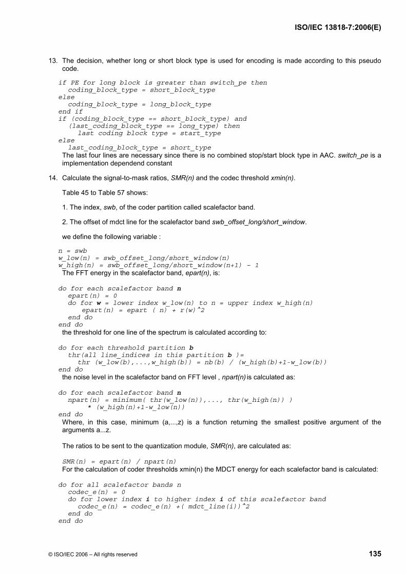
ISO/IEC 13818-7:2006(E)
© ISO/IEC 2006 – All rights reserved 135
13. The decision, whether long or short block type is used for encoding is made according to this pseudo code.
if PE for long block is greater than switch_pe then coding_block_type = short_block_type else coding_block_type = long_block_type end if if (coding_block_type == short_block_type) and (last_coding_block_type == long_type) then last coding block type = start_type else last_coding_block_type = short_type
The last four lines are necessary since there is no combined stop/start block type in AAC. switch_pe is a implementation dependend constant
14. Calculate the signal-to-mask ratios, SMR(n) and the codec threshold xmin(n).
Table 45 to Table 57 shows:
1. The index, swb, of the coder partition called scalefactor band.
2. The offset of mdct line for the scalefactor band swb_offset_long/short_window.
we define the following variable :
n = swb w_low(n) = swb_offset_long/short_window(n) w_high(n) = swb_offset_long/short_window(n+1) – 1
The FFT energy in the scalefactor band, epart(n), is:
do for each scalefactor band n epart(n) = 0 do for w = lower index w_low(n) to n = upper index w_high(n) epart(n) = epart ( n) + r(w)^2 end do end do
the threshold for one line of the spectrum is calculated according to:
do for each threshold partition b thr(all line_indices in this partition b )= thr (w_low(b),...,w_high(b)) = nb(b) / (w_high(b)+1-w_low(b)) end do
the noise level in the scalefactor band on FFT level , npart(n) is calculated as:
do for each scalefactor band n npart(n) = minimum( thr(w_low(n)),..., thr(w_high(n)) ) * (w_high(n)+1-w_low(n)) end do
Where, in this case, minimum (a,...,z) is a function returning the smallest positive argument of the arguments a...z.
The ratios to be sent to the quantization module, SMR(n), are calculated as:
SMR(n) = epart(n) / npart(n) For the calculation of coder thresholds xmin(n) the MDCT energy for each scalefactor band is calculated:
do for all scalefactor bands n codec_e(n) = 0 do for lower index i to higher index i of this scalefactor band codec_e(n) = codec_e(n) +( mdct_line(i))^2 end do end do

ISO/IEC 13818-7:2006(E)
136 © ISO/IEC 2006 – All rights reserved
Then xmin(n), the maximum allowed error energy on MDCT level, can be calculated according to this formula:
xmin (n) = npart(n) * codec_e(n) / epart (n)
15. Calculate the bit allocation out of the psychoacoustic entropy (PE). bit_allocation = pew1* PE + pew2*sqrt(PE);
for long blocks the constants are defined as:
pew1 = 0.3 , pew2 = 6.0 for short blocks the PE of the eight short blocks is summed up and the constants are :
pew1 = 0.6 , pew2 = 24 then bit_allocation is limited to 0<bit_allocation < 3000 and more_bits is calculated :
more_bits = bit_allocation - (mean_bits - side_info_bits)

ISO/IEC 13818-7:2006(E)
© ISO/IEC 2006 – All rights reserved 137
calculate unpredictability measure cw
FFT (long and short) (windowsize long 2048 windowsize short 256)
calculate threshold (part 1)
perceptual entropy > switch_pe ?
calculate perceptual entropy
input buffer
delay compensation for filterbank
YN
use short blocks
use long blocks
calculate threshold (part 2) calculate threshold for short blocks
output buffer: blocktype, threshold (ratio), perceptual entropy, time signal
delay threshold (ratio), blocktype, perceptual entropy by one block if (window_sequence(n) == EIGHT_SHORT_SEQUENCE && window_sequence(n-1) == ONLY_LONG_SEQUENCE) window_sequence(n-1) = LONG_START_SEQUENCE;
Figure C.1 — Block diagram psychoacoustic model

ISO/IEC 13818-7:2006(E)
138 © ISO/IEC 2006 – All rights reserved
Table C.1 — Psychoacoustic parameters for 8 kHz long FFT
index w_low w_high width bval qsthr 0 0 8 9 0.18 46.82 1 9 17 9 0.53 46.82 2 18 26 9 0.89 46.82 3 27 35 9 1.24 41.82 4 36 44 9 1.59 41.82 5 45 53 9 1.94 41.82 6 54 62 9 2.29 38.82 7 63 71 9 2.63 38.82 8 72 80 9 2.98 38.82 9 81 89 9 3.31 33.82 10 90 98 9 3.65 33.82 11 99 108 10 3.99 34.28 12 109 118 10 4.35 32.28 13 119 128 10 4.71 32.28 14 129 138 10 5.05 32.28 15 139 148 10 5.39 32.28 16 149 159 11 5.74 32.69 17 160 170 11 6.10 32.69 18 171 181 11 6.45 32.69 19 182 192 11 6.79 32.69 20 193 204 12 7.13 33.07 21 205 216 12 7.48 33.07 22 217 228 12 7.82 33.07 23 229 241 13 8.17 33.42 24 242 254 13 8.51 33.42 25 255 268 14 8.85 33.74 26 269 282 14 9.20 33.74 27 283 297 15 9.54 34.04 28 298 312 15 9.88 34.04 29 313 328 16 10.22 34.32 30 329 345 17 10.56 34.58 31 346 363 18 10.91 34.83 32 364 381 18 11.25 34.83 33 382 400 19 11.58 35.06 34 401 420 20 11.91 35.29 35 421 441 21 12.24 35.50 36 442 464 23 12.58 35.89 37 465 488 24 12.92 36.08 38 489 514 26 13.26 36.43 39 515 541 27 13.59 36.59 40 542 570 29 13.93 36.90 41 571 601 31 14.26 37.19 42 602 634 33 14.60 37.46 43 635 670 36 14.93 37.84 44 671 708 38 15.27 38.07 45 709 749 41 15.60 38.40 46 750 793 44 15.93 38.71 47 794 841 48 16.26 39.09 48 842 893 52 16.60 39.44 49 894 949 56 16.93 39.76 50 950 1009 60 17.26 40.06 51 1010 1023 14 17.47 33.74

ISO/IEC 13818-7:2006(E)
© ISO/IEC 2006 – All rights reserved 139
Table C.2 — Psychoacoustic parameters for 8 kHz short FFT
index w_low w_high width bval qsthr 0 0 1 2 0.32 30.29 1 2 3 2 0.95 30.29 2 4 5 2 1.57 25.29 3 6 7 2 2.19 22.29 4 8 9 2 2.80 22.29 5 10 11 2 3.40 17.29 6 12 13 2 3.99 17.29 7 14 15 2 4.56 15.29 8 16 17 2 5.12 15.29 9 18 19 2 5.66 15.29 10 20 21 2 6.18 15.29 11 22 23 2 6.68 15.29 12 24 25 2 7.16 15.29 13 26 27 2 7.63 15.29 14 28 29 2 8.07 15.29 15 30 31 2 8.50 15.29 16 32 33 2 8.90 15.29 17 34 35 2 9.29 15.29 18 36 37 2 9.67 15.29 19 38 39 2 10.03 15.29 20 40 41 2 10.37 15.29 21 42 44 3 10.77 17.05 22 45 47 3 11.23 17.05 23 48 50 3 11.66 17.05 24 51 53 3 12.06 17.05 25 54 56 3 12.44 17.05 26 57 59 3 12.79 17.05 27 60 63 4 13.18 18.30 28 64 67 4 13.59 18.30 29 68 71 4 13.97 18.30 30 72 75 4 14.32 18.30 31 76 80 5 14.69 19.27 32 81 85 5 15.07 19.27 33 86 90 5 15.42 19.27 34 91 96 6 15.77 20.06 35 97 102 6 16.13 20.06 36 103 109 7 16.49 20.73 37 110 116 7 16.85 20.73 38 117 124 8 17.20 21.31 39 125 127 3 17.44 17.05

ISO/IEC 13818-7:2006(E)
140 © ISO/IEC 2006 – All rights reserved
Table C.3 — Psychoacoustic parameters for 11.025 kHz long FFT
index w_low w_high width bval qsthr 0 0 6 7 0.19 45.73 1 7 13 7 0.57 45.73 2 14 20 7 0.95 45.73 3 21 27 7 1.33 40.73 4 28 34 7 1.71 40.73 5 35 41 7 2.08 37.73 6 42 48 7 2.45 37.73 7 49 55 7 2.82 37.73 8 56 62 7 3.18 32.73 9 63 69 7 3.54 32.73
10 70 76 7 3.89 32.73 11 77 83 7 4.24 30.73 12 84 90 7 4.59 30.73 13 91 97 7 4.92 30.73 14 98 105 8 5.28 31.31 15 106 113 8 5.65 31.31 16 114 121 8 6.01 31.31 17 122 129 8 6.36 31.31 18 130 137 8 6.70 31.31 19 138 146 9 7.06 31.82 20 147 155 9 7.42 31.82 21 156 164 9 7.77 31.82 22 165 173 9 8.11 31.82 23 174 183 10 8.46 32.28 24 184 193 10 8.82 32.28 25 194 203 10 9.16 32.28 26 204 214 11 9.50 32.69 27 215 225 11 9.85 32.69 28 226 237 12 10.19 33.07 29 238 249 12 10.54 33.07 30 250 262 13 10.88 33.42 31 263 275 13 11.22 33.42 32 276 289 14 11.56 33.74 33 290 304 15 11.90 34.04 34 305 320 16 12.24 34.32 35 321 337 17 12.59 34.58 36 338 355 18 12.94 34.83 37 356 374 19 13.28 35.06 38 375 394 20 13.62 35.29 39 395 415 21 13.96 35.50 40 416 438 23 14.29 35.89 41 439 462 24 14.63 36.08 42 463 488 26 14.96 36.43 43 489 516 28 15.29 36.75 44 517 546 30 15.63 37.05 45 547 579 33 15.96 37.46 46 580 614 35 16.30 37.72 47 615 652 38 16.63 38.07 48 653 693 41 16.97 38.40 49 694 737 44 17.30 38.71 50 738 785 48 17.64 39.09 51 786 836 51 17.97 39.35 52 837 891 55 18.30 39.68 53 892 950 59 18.64 39.98 54 951 1014 64 18.97 40.34 55 1015 1023 9 19.16 31.82

ISO/IEC 13818-7:2006(E)
© ISO/IEC 2006 – All rights reserved 141
Table C.4 — Psychoacoustic parameters for 11.025 kHz short FFT
index w_low w_high width bval qsthr 0 0 0 1 0.00 27.28 1 1 1 1 0.44 27.28 2 2 2 1 0.87 27.28 3 3 3 1 1.30 22.28 4 4 4 1 1.73 22.28 5 5 5 1 2.16 19.28 6 6 6 1 2.58 19.28 7 7 7 1 3.00 14.28 8 8 8 1 3.41 14.28 9 9 9 1 3.82 14.28 10 10 10 1 4.22 12.28 11 11 11 1 4.61 12.28 12 12 12 1 4.99 12.28 13 13 13 1 5.37 12.28 14 14 14 1 5.74 12.28 15 15 15 1 6.10 12.28 16 16 16 1 6.45 12.28 17 17 17 1 6.79 12.28 18 18 19 2 7.44 15.29 19 20 21 2 8.05 15.29 20 22 23 2 8.64 15.29 21 24 25 2 9.19 15.29 22 26 27 2 9.70 15.29 23 28 29 2 10.19 15.29 24 30 31 2 10.65 15.29 25 32 33 2 11.08 15.29 26 34 35 2 11.48 15.29 27 36 37 2 11.86 15.29 28 38 39 2 12.22 15.29 29 40 42 3 12.64 17.05 30 43 45 3 13.10 17.05 31 46 48 3 13.53 17.05 32 49 51 3 13.93 17.05 33 52 54 3 14.30 17.05 34 55 58 4 14.69 18.30 35 59 62 4 15.11 18.30 36 63 66 4 15.49 18.30 37 67 70 4 15.84 18.30 38 71 75 5 16.21 19.27 39 76 80 5 16.58 19.27 40 81 85 5 16.92 19.27 41 86 91 6 17.27 20.06 42 92 97 6 17.62 20.06 43 98 104 7 17.97 20.73 44 105 111 7 18.32 20.73 45 112 119 8 18.67 21.31 46 120 127 8 19.02 21.31

ISO/IEC 13818-7:2006(E)
142 © ISO/IEC 2006 – All rights reserved
Table C.5 — Psychoacoustic parameters for 12 kHz long FFT
index w_low w_high width bval qsthr 0 0 5 6 0.18 45.06 1 6 11 6 0.53 45.06 2 12 17 6 0.89 45.06 3 18 23 6 1.24 40.06 4 24 29 6 1.59 40.06 5 30 35 6 1.94 40.06 6 36 41 6 2.29 37.06 7 42 47 6 2.63 37.06 8 48 53 6 2.98 37.06 9 54 59 6 3.31 32.06
10 60 65 6 3.65 32.06 11 66 72 7 4.00 30.73 12 73 79 7 4.38 30.73 13 80 86 7 4.75 30.73 14 87 93 7 5.11 30.73 15 94 100 7 5.47 30.73 16 101 107 7 5.82 30.73 17 108 114 7 6.15 30.73 18 115 122 8 6.51 31.31 19 123 130 8 6.88 31.31 20 131 138 8 7.24 31.31 21 139 146 8 7.58 31.31 22 147 154 8 7.92 31.31 23 155 163 9 8.27 31.82 24 164 172 9 8.62 31.82 25 173 181 9 8.96 31.82 26 182 191 10 9.31 32.28 27 192 201 10 9.66 32.28 28 202 212 11 10.01 32.69 29 213 223 11 10.36 32.69 30 224 235 12 10.71 33.07 31 236 247 12 11.06 33.07 32 248 260 13 11.41 33.42 33 261 273 13 11.75 33.42 34 274 287 14 12.09 33.74 35 288 302 15 12.43 34.04 36 303 318 16 12.77 34.32 37 319 335 17 13.11 34.58 38 336 353 18 13.46 34.83 39 354 372 19 13.80 35.06 40 373 392 20 14.13 35.29 41 393 414 22 14.47 35.70 42 415 437 23 14.81 35.89 43 438 462 25 15.14 36.26 44 463 489 27 15.48 36.59 45 490 518 29 15.81 36.90 46 519 549 31 16.15 37.19 47 550 583 34 16.48 37.59 48 584 619 36 16.82 37.84 49 620 658 39 17.15 38.19 50 659 700 42 17.48 38.51 51 701 745 45 17.81 38.81 52 746 794 49 18.14 39.18 53 795 847 53 18.48 39.52 54 848 904 57 18.81 39.83 55 905 965 61 19.15 40.13 56 966 1023 58 19.47 39.91

ISO/IEC 13818-7:2006(E)
© ISO/IEC 2006 – All rights reserved 143
Table C.6 — Psychoacoustic parameters for 12 kHz short FFT
index w_low w_high width bval qsthr 0 0 0 1 0.00 27.28 1 1 1 1 0.47 27.28 2 2 2 1 0.95 27.28 3 3 3 1 1.42 22.28 4 4 4 1 1.88 22.28 5 5 5 1 2.35 19.28 6 6 6 1 2.81 19.28 7 7 7 1 3.26 14.28 8 8 8 1 3.70 14.28 9 9 9 1 4.14 12.28 10 10 10 1 4.57 12.28 11 11 11 1 4.98 12.28 12 12 12 1 5.39 12.28 13 13 13 1 5.79 12.28 14 14 14 1 6.18 12.28 15 15 15 1 6.56 12.28 16 16 16 1 6.93 12.28 17 17 17 1 7.28 12.28 18 18 18 1 7.63 12.28 19 19 20 2 8.28 15.29 20 21 22 2 8.90 15.29 21 23 24 2 9.48 15.29 22 25 26 2 10.02 15.29 23 27 28 2 10.53 15.29 24 29 30 2 11.00 15.29 25 31 32 2 11.45 15.29 26 33 34 2 11.86 15.29 27 35 36 2 12.25 15.29 28 37 38 2 12.62 15.29 29 39 40 2 12.96 15.29 30 41 43 3 13.36 17.05 31 44 46 3 13.80 17.05 32 47 49 3 14.21 17.05 33 50 52 3 14.59 17.05 34 53 55 3 14.94 17.05 35 56 59 4 15.32 18.30 36 60 63 4 15.71 18.30 37 64 67 4 16.08 18.30 38 68 72 5 16.45 19.27 39 73 77 5 16.83 19.27 40 78 82 5 17.19 19.27 41 83 88 6 17.54 20.06 42 89 94 6 17.90 20.06 43 95 101 7 18.26 20.73 44 102 108 7 18.62 20.73 45 109 116 8 18.97 21.31 46 117 124 8 19.32 21.31 47 125 127 3 19.55 17.05

ISO/IEC 13818-7:2006(E)
144 © ISO/IEC 2006 – All rights reserved
Table C.7 — Psychoacoustic parameters for 16 kHz long FFT
index w_low w_high width bval qsthr 0 0 4 5 0.20 43.30 1 5 9 5 0.59 43.10 2 10 14 5 0.99 38.30 3 15 19 5 1.38 38.10 4 20 24 5 1.77 38.00 5 25 29 5 2.16 35.10 6 30 34 5 2.54 35.30 7 35 39 5 2.92 30.00 8 40 44 5 3.29 30.00 9 45 49 5 3.66 28.30 10 50 54 5 4.03 28.30 11 55 59 5 4.39 28.30 12 60 64 5 4.74 28.30 13 65 69 5 5.09 28.30 14 70 74 5 5.43 28.30 15 75 80 6 5.79 28.30 16 81 86 6 6.18 28.30 17 87 92 6 6.56 28.00 18 93 98 6 6.92 29.27 19 99 104 6 7.28 29.27 20 105 110 6 7.63 29.27 21 111 116 6 7.96 29.27 22 117 123 7 8.31 29.27 23 124 130 7 8.68 29.06 24 131 137 7 9.03 30.06 25 138 144 7 9.37 30.06 26 145 152 8 9.71 30.06 27 153 160 8 10.07 30.73 28 161 168 8 10.41 30.73 29 169 177 9 10.75 30.73 30 178 186 9 11.10 31.31 31 187 196 10 11.45 31.31 32 197 206 10 11.80 31.82 33 207 217 11 12.14 31.82 34 218 228 11 12.48 32.28 35 229 240 12 12.82 32.28 36 241 253 13 13.16 32.69 37 254 267 14 13.51 32.69 38 268 282 15 13.86 33.07 39 283 298 16 14.21 33.46 40 299 315 17 14.56 33.82 41 316 333 18 14.90 34.12 42 334 352 19 15.24 34.42 43 353 373 21 15.58 34.68 44 374 395 22 15.91 35.15 45 396 419 24 16.25 35.32 46 420 445 26 16.58 35.73 47 446 473 28 16.92 35.91 48 474 503 30 17.25 36.42 49 504 536 33 17.59 36.75 50 537 571 35 17.93 37.11 51 572 609 38 18.26 37.34 52 610 650 41 18.60 37.63 53 651 694 44 18.94 38.12

ISO/IEC 13818-7:2006(E)
© ISO/IEC 2006 – All rights reserved 145
54 695 741 47 19.27 38.17 55 742 791 50 19.60 41.52 56 792 845 54 19.94 41.84 57 846 903 58 20.27 42.13 58 904 965 62 20.61 44.41 59 966 1023 58 20.92 44.87
Table C.8 — Psychoacoustic parameters for 16 kHz short FFT
index w_low w_high width bval qsthr 0 0 0 1 0.00 27.28 1 1 1 1 0.63 27.28 2 2 2 1 1.26 22.28 3 3 3 1 1.88 22.28 4 4 4 1 2.50 19.28 5 5 5 1 3.11 14.28 6 6 6 1 3.70 14.28 7 7 7 1 4.28 12.28 8 8 8 1 4.85 12.28 9 9 9 1 5.39 12.28
10 10 10 1 5.92 12.28 11 11 11 1 6.43 12.28 12 12 12 1 6.93 12.28 13 13 13 1 7.40 12.28 14 14 14 1 7.85 12.28 15 15 15 1 8.29 12.28 16 16 16 1 8.70 12.28 17 17 17 1 9.10 12.28 18 18 18 1 9.49 12.28 19 19 19 1 9.85 12.28 20 20 20 1 10.20 12.28 21 21 22 2 10.85 15.29 22 23 24 2 11.44 15.29 23 25 26 2 11.99 15.29 24 27 28 2 12.50 15.29 25 29 30 2 12.96 15.29 26 31 32 2 13.39 15.29 27 33 34 2 13.78 15.29 28 35 36 2 14.15 15.29 29 37 39 3 14.57 17.05 30 40 42 3 15.03 17.05 31 43 45 3 15.45 17.05 32 46 48 3 15.84 17.05 33 49 51 3 16.19 17.05 34 52 55 4 16.57 18.30 35 56 59 4 16.97 18.30 36 60 63 4 17.33 18.30 37 64 68 5 17.71 19.27 38 69 73 5 18.09 19.27 39 74 78 5 18.44 19.27 40 79 84 6 18.80 20.06 41 85 90 6 19.17 20.06 42 91 97 7 19.53 20.73 43 98 104 7 19.89 20.73 44 105 112 8 20.25 24.31 45 113 120 8 20.61 24.31 46 121 127 7 20.92 23.73

ISO/IEC 13818-7:2006(E)
146 © ISO/IEC 2006 – All rights reserved
Table C.9 — Psychoacoustic parameters for 22.05 kHz long FFT
index w_low w_high width bval qsthr 0 0 3 4 0.22 43.30 1 4 7 4 0.65 43.30 2 8 11 4 1.09 38.30 3 12 15 4 1.52 38.30 4 16 19 4 1.95 38.30 5 20 23 4 2.37 35.30 6 24 27 4 2.79 35.30 7 28 31 4 3.21 30.30 8 32 35 4 3.62 30.30 9 36 39 4 4.02 28.30
10 40 43 4 4.41 28.30 11 44 47 4 4.80 28.30 12 48 51 4 5.18 28.30 13 52 55 4 5.55 28.30 14 56 59 4 5.92 28.30 15 60 63 4 6.27 28.30 16 64 67 4 6.62 28.30 17 68 71 4 6.95 28.30 18 72 76 5 7.32 29.27 19 77 81 5 7.71 29.27 20 82 86 5 8.10 29.27 21 87 91 5 8.46 29.27 22 92 96 5 8.82 29.27 23 97 101 5 9.16 29.27 24 102 107 6 9.52 30.06 25 108 113 6 9.89 30.06 26 114 119 6 10.25 30.06 27 120 125 6 10.59 30.06 28 126 132 7 10.95 30.73 29 133 139 7 11.31 30.73 30 140 146 7 11.65 30.73 31 147 154 8 12.00 31.31 32 155 162 8 12.35 31.31 33 163 171 9 12.70 31.82 34 172 180 9 13.05 31.82 35 181 190 10 13.40 32.28 36 191 200 10 13.74 32.28 37 201 211 11 14.07 32.69 38 212 223 12 14.41 33.07 39 224 236 13 14.76 33.42 40 237 250 14 15.11 33.74 41 251 265 15 15.46 34.04 42 266 281 16 15.80 34.32 43 282 298 17 16.14 34.58 44 299 317 19 16.48 35.06 45 318 337 20 16.82 35.29 46 338 359 22 17.16 35.70 47 360 382 23 17.50 35.89 48 383 407 25 17.84 36.26 49 408 434 27 18.17 36.59 50 435 463 29 18.51 36.90 51 464 494 31 18.84 37.19 52 495 527 33 19.17 37.46 53 528 563 36 19.51 37.84 54 564 601 38 19.84 38.07 55 602 642 41 20.17 41.40 56 643 686 44 20.50 41.71 57 687 733 47 20.84 42.00 58 734 784 51 21.17 44.35

ISO/IEC 13818-7:2006(E)
© ISO/IEC 2006 – All rights reserved 147
59 785 839 55 21.50 44.68 60 840 898 59 21.84 44.98 61 899 962 64 22.17 50.34 62 963 1023 61 22.48 50.13
Table C.10 — Psychoacoustic parameters for 22.05 kHz short FFT
index w_low w_high width bval qsthr 0 0 0 1 0.00 27.28 1 1 1 1 0.87 27.28 2 2 2 1 1.73 22.28 3 3 3 1 2.58 19.28 4 4 4 1 3.41 14.28 5 5 5 1 4.22 12.28 6 6 6 1 4.99 12.28 7 7 7 1 5.74 12.28 8 8 8 1 6.45 12.28 9 9 9 1 7.12 12.28 10 10 10 1 7.75 12.28 11 11 11 1 8.36 12.28 12 12 12 1 8.92 12.28 13 13 13 1 9.45 12.28 14 14 14 1 9.96 12.28 15 15 15 1 10.43 12.28 16 16 16 1 10.87 12.28 17 17 17 1 11.29 12.28 18 18 18 1 11.68 12.28 19 19 19 1 12.05 12.28 20 20 21 2 12.71 15.29 21 22 23 2 13.32 15.29 22 24 25 2 13.86 15.29 23 26 27 2 14.35 15.29 24 28 29 2 14.80 15.29 25 30 31 2 15.21 15.29 26 32 33 2 15.58 15.29 27 34 35 2 15.93 15.29 28 36 38 3 16.32 17.05 29 39 41 3 16.75 17.05 30 42 44 3 17.15 17.05 31 45 47 3 17.51 17.05 32 48 51 4 17.89 18.30 33 52 55 4 18.30 18.30 34 56 59 4 18.67 18.30 35 60 63 4 19.02 18.30 36 64 68 5 19.37 19.27 37 69 73 5 19.74 19.27 38 74 78 5 20.09 22.27 39 79 84 6 20.44 23.06 40 85 90 6 20.79 23.06 41 91 97 7 21.15 25.73 42 98 104 7 21.50 25.73 43 105 112 8 21.85 26.31 44 113 120 8 22.20 31.31 45 121 127 7 22.49 30.73

ISO/IEC 13818-7:2006(E)
148 © ISO/IEC 2006 – All rights reserved
Table C.11 — Psychoacoustic parameters for 24 kHz long FFT
index w_low w_high width bval qsthr 0 0 2 3 0.18 42.05 1 3 5 3 0.53 42.05 2 6 8 3 0.89 42.05 3 9 11 3 1.24 37.05 4 12 14 3 1.59 37.05 5 15 17 3 1.94 37.05 6 18 20 3 2.29 34.05 7 21 23 3 2.63 34.05 8 24 26 3 2.98 34.05 9 27 29 3 3.31 29.05 10 30 32 3 3.65 29.05 11 33 36 4 4.03 28.30 12 37 40 4 4.46 28.30 13 41 44 4 4.88 28.30 14 45 48 4 5.29 28.30 15 49 52 4 5.69 28.30 16 53 56 4 6.08 28.30 17 57 60 4 6.46 28.30 18 61 64 4 6.83 28.30 19 65 68 4 7.19 28.30 20 69 72 4 7.54 28.30 21 73 76 4 7.88 28.30 22 77 81 5 8.25 29.27 23 82 86 5 8.64 29.27 24 87 91 5 9.02 29.27 25 92 96 5 9.38 29.27 26 97 101 5 9.73 29.27 27 102 107 6 10.09 30.06 28 108 113 6 10.47 30.06 29 114 119 6 10.83 30.06 30 120 125 6 11.18 30.06 31 126 132 7 11.53 30.73 32 133 139 7 11.89 30.73 33 140 146 7 12.23 30.73 34 147 154 8 12.57 31.31 35 155 162 8 12.92 31.31 36 163 171 9 13.26 31.82 37 172 180 9 13.61 31.82 38 181 190 10 13.95 32.28 39 191 201 11 14.29 32.69 40 202 213 12 14.65 33.07 41 214 225 12 15.00 33.07 42 226 238 13 15.33 33.42 43 239 252 14 15.66 33.74 44 253 267 15 16.00 34.04 45 268 284 17 16.34 34.58 46 285 302 18 16.69 34.83 47 303 321 19 17.02 35.06 48 322 342 21 17.36 35.50 49 343 364 22 17.70 35.70 50 365 388 24 18.03 36.08 51 389 414 26 18.37 36.43 52 415 442 28 18.70 36.75 53 443 472 30 19.04 37.05
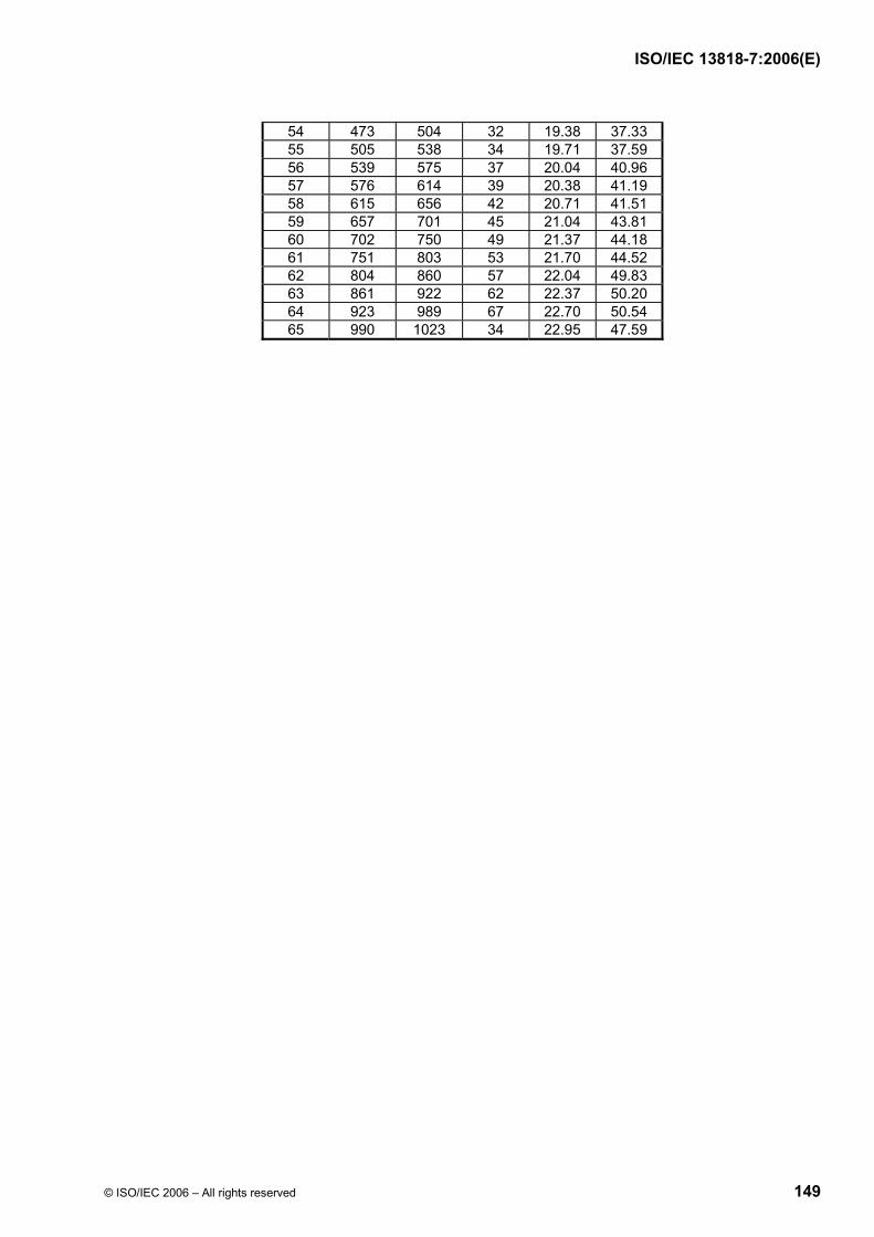
ISO/IEC 13818-7:2006(E)
© ISO/IEC 2006 – All rights reserved 149
54 473 504 32 19.38 37.33 55 505 538 34 19.71 37.59 56 539 575 37 20.04 40.96 57 576 614 39 20.38 41.19 58 615 656 42 20.71 41.51 59 657 701 45 21.04 43.81 60 702 750 49 21.37 44.18 61 751 803 53 21.70 44.52 62 804 860 57 22.04 49.83 63 861 922 62 22.37 50.20 64 923 989 67 22.70 50.54 65 990 1023 34 22.95 47.59

ISO/IEC 13818-7:2006(E)
150 © ISO/IEC 2006 – All rights reserved
Table C.12 — Psychoacoustic parameters for 24 kHz short FFT
index w_low w_high width bval qsthr 0 0 0 1 0.00 27.28 1 1 1 1 0.95 27.28 2 2 2 1 1.88 22.28 3 3 3 1 2.81 19.28 4 4 4 1 3.70 14.28 5 5 5 1 4.57 12.28 6 6 6 1 5.39 12.28 7 7 7 1 6.18 12.28 8 8 8 1 6.93 12.28 9 9 9 1 7.63 12.28 10 10 10 1 8.29 12.28 11 11 11 1 8.91 12.28 12 12 12 1 9.49 12.28 13 13 13 1 10.03 12.28 14 14 14 1 10.53 12.28 15 15 15 1 11.01 12.28 16 16 16 1 11.45 12.28 17 17 17 1 11.87 12.28 18 18 18 1 12.26 12.28 19 19 19 1 12.62 12.28 20 20 21 2 13.28 15.29 21 22 23 2 13.87 15.29 22 24 25 2 14.40 15.29 23 26 27 2 14.88 15.29 24 28 29 2 15.32 15.29 25 30 31 2 15.71 15.29 26 32 33 2 16.08 15.29 27 34 36 3 16.49 17.05 28 37 39 3 16.94 17.05 29 40 42 3 17.35 17.05 30 43 45 3 17.73 17.05 31 46 48 3 18.07 17.05 32 49 52 4 18.44 18.30 33 53 56 4 18.83 18.30 34 57 60 4 19.20 18.30 35 61 65 5 19.57 19.27 36 66 70 5 19.96 19.27 37 71 75 5 20.31 22.27 38 76 81 6 20.67 23.06 39 82 87 6 21.04 25.06 40 88 94 7 21.41 25.73 41 95 101 7 21.77 25.73 42 102 109 8 22.13 31.31 43 110 117 8 22.48 31.31 44 118 126 9 22.82 31.82 45 127 127 1 23.01 32.28

ISO/IEC 13818-7:2006(E)
© ISO/IEC 2006 – All rights reserved 151
Table C.13 — Psychoacoustic parameters for 32 kHz long FFT
index w_low w_high width bval qsthr 0 0 2 3 0.24 42.05 1 3 5 3 0.71 42.05 2 6 8 3 1.18 37.05 3 9 11 3 1.65 37.05 4 12 14 3 2.12 34.05 5 15 17 3 2.58 34.05 6 18 20 3 3.03 29.05 7 21 23 3 3.48 29.05 8 24 26 3 3.92 29.05 9 27 29 3 4.35 27.05
10 30 32 3 4.77 27.05 11 33 35 3 5.19 27.05 12 36 38 3 5.59 27.05 13 39 41 3 5.99 27.05 14 42 44 3 6.37 27.05 15 45 47 3 6.74 27.05 16 48 50 3 7.10 27.05 17 51 53 3 7.45 27.05 18 54 56 3 7.80 27.05 19 57 60 4 8.18 28.30 20 61 64 4 8.60 28.30 21 65 68 4 9.00 28.30 22 69 72 4 9.39 28.30 23 73 76 4 9.76 28.30 24 77 80 4 10.11 28.30 25 81 84 4 10.45 28.30 26 85 89 5 10.81 29.27 27 90 94 5 11.19 29.27 28 95 99 5 11.55 29.27 29 100 104 5 11.90 29.27 30 105 110 6 12.25 30.06 31 111 116 6 12.62 30.06 32 117 122 6 12.96 30.06 33 123 129 7 13.31 30.73 34 130 136 7 13.66 30.73 35 137 144 8 14.01 31.31 36 145 152 8 14.36 31.31 37 153 161 9 14.71 31.82 38 162 171 10 15.07 32.28 39 172 181 10 15.42 32.28 40 182 192 11 15.76 32.69 41 193 204 12 16.10 33.07 42 205 217 13 16.45 33.42 43 218 231 14 16.80 33.74 44 232 246 15 17.14 34.04 45 247 262 16 17.48 34.32 46 263 279 17 17.82 34.58 47 280 298 19 18.15 35.06 48 299 318 20 18.49 35.29 49 319 340 22 18.84 35.70 50 341 363 23 19.17 35.89 51 364 388 25 19.51 36.26 52 389 415 27 19.85 36.59 53 416 444 29 20.19 39.90 54 445 475 31 20.53 40.19 55 476 508 33 20.87 40.46 56 509 543 35 21.20 42.72 57 544 581 38 21.53 43.07 58 582 622 41 21.86 43.40

ISO/IEC 13818-7:2006(E)
152 © ISO/IEC 2006 – All rights reserved
59 623 667 45 22.20 48.81 60 668 715 48 22.53 49.09 61 716 768 53 22.86 49.52 62 769 826 58 23.20 59.91 63 827 890 64 23.53 60.34 64 891 961 71 23.86 60.79 65 962 1023 62 24.00 65.89
Table C.14 — Psychoacoustic parameters for 32 kHz short FFT
index w_low w_high width bval qsthr 0 0 0 1 0.00 27.28 1 1 1 1 1.26 22.28 2 2 2 1 2.50 19.28 3 3 3 1 3.70 14.28 4 4 4 1 4.85 12.28 5 5 5 1 5.92 12.28 6 6 6 1 6.93 12.28 7 7 7 1 7.85 12.28 8 8 8 1 8.70 12.28 9 9 9 1 9.49 12.28 10 10 10 1 10.20 12.28 11 11 11 1 10.85 12.28 12 12 12 1 11.45 12.28 13 13 13 1 12.00 12.28 14 14 14 1 12.50 12.28 15 15 15 1 12.96 12.28 16 16 16 1 13.39 12.28 17 17 17 1 13.78 12.28 18 18 18 1 14.15 12.28 19 19 20 2 14.80 15.29 20 21 22 2 15.38 15.29 21 23 24 2 15.89 15.29 22 25 26 2 16.36 15.29 23 27 28 2 16.77 15.29 24 29 30 2 17.15 15.29 25 31 32 2 17.50 15.29 26 33 35 3 17.90 17.05 27 36 38 3 18.34 17.05 28 39 41 3 18.74 17.05 29 42 44 3 19.11 17.05 30 45 48 4 19.50 18.30 31 49 52 4 19.92 18.30 32 53 56 4 20.30 21.30 33 57 60 4 20.65 21.30 34 61 65 5 21.02 24.27 35 66 70 5 21.40 24.27 36 71 75 5 21.75 24.27 37 76 81 6 22.10 30.06 38 82 87 6 22.45 30.06 39 88 94 7 22.80 30.73 40 95 102 8 23.16 41.31 41 103 110 8 23.51 41.31 42 111 119 9 23.85 41.82 43 120 127 8 24.00 60.47

ISO/IEC 13818-7:2006(E)
© ISO/IEC 2006 – All rights reserved 153
Table C.15 – Psychoacoustic parameters for 44.1 kHz long FFT
index w_low w_high width bval qsthr 0 0 1 2 0.22 40.29 1 2 3 2 0.65 40.29 2 4 5 2 1.09 35.29 3 6 7 2 1.52 35.29 4 8 9 2 1.95 35.29 5 10 11 2 2.37 32.29 6 12 13 2 2.79 32.29 7 14 15 2 3.21 27.29 8 16 17 2 3.62 27.29 9 18 19 2 4.02 25.29 10 20 21 2 4.41 25.29 11 22 23 2 4.80 25.29 12 24 25 2 5.18 25.29 13 26 27 2 5.55 25.29 14 28 29 2 5.92 25.29 15 30 31 2 6.27 25.29 16 32 33 2 6.62 25.29 17 34 35 2 6.95 25.29 18 36 38 3 7.36 27.05 19 39 41 3 7.83 27.05 20 42 44 3 8.28 27.05 21 45 47 3 8.71 27.05 22 48 50 3 9.12 27.05 23 51 53 3 9.52 27.05 24 54 56 3 9.89 27.05 25 57 59 3 10.25 27.05 26 60 62 3 10.59 27.05 27 63 66 4 10.97 28.30 28 67 70 4 11.38 28.30 29 71 74 4 11.77 28.30 30 75 78 4 12.13 28.30 31 79 82 4 12.48 28.30 32 83 87 5 12.84 29.27 33 88 92 5 13.22 29.27 34 93 97 5 13.57 29.27 35 98 103 6 13.93 30.06 36 104 109 6 14.30 30.06 37 110 116 7 14.67 30.73 38 117 123 7 15.03 30.73 39 124 131 8 15.40 31.31 40 132 139 8 15.76 31.31 41 140 148 9 16.11 31.82 42 149 157 9 16.45 31.82 43 158 167 10 16.79 32.28 44 168 178 11 17.13 32.69 45 179 190 12 17.48 33.07 46 191 203 13 17.83 33.42 47 204 217 14 18.18 33.74 48 218 232 15 18.52 34.04 49 233 248 16 18.87 34.32 50 249 265 17 19.21 34.58 51 266 283 18 19.54 34.83 52 284 303 20 19.88 35.29 53 304 324 21 20.22 38.50

ISO/IEC 13818-7:2006(E)
154 © ISO/IEC 2006 – All rights reserved
54 325 347 23 20.56 38.89 55 348 371 24 20.90 39.08 56 372 397 26 21.24 41.43 57 398 425 28 21.57 41.75 58 426 455 30 21.91 42.05 59 456 488 33 22.24 47.46 60 489 524 36 22.58 47.84 61 525 563 39 22.91 48.19 62 564 606 43 23.25 58.61 63 607 653 47 23.58 59.00 64 654 706 53 23.91 59.52 65 707 765 59 24.00 69.98 66 766 832 67 24.00 70.54 67 833 908 76 24.00 71.08 68 909 996 88 24.00 71.72 69 997 1023 27 24.00 72.09

ISO/IEC 13818-7:2006(E)
© ISO/IEC 2006 – All rights reserved 155
Table C.16 — Psychoacoustic parameters for 44.1 kHz short FFT
index w_low w_high width bval qsthr 0 0 0 1 0.00 27.28 1 1 1 1 1.73 22.28 2 2 2 1 3.41 14.28 3 3 3 1 4.99 12.28 4 4 4 1 6.45 12.28 5 5 5 1 7.75 12.28 6 6 6 1 8.92 12.28 7 7 7 1 9.96 12.28 8 8 8 1 10.87 12.28 9 9 9 1 11.68 12.28 10 10 10 1 12.39 12.28 11 11 11 1 13.03 12.28 12 12 12 1 13.61 12.28 13 13 13 1 14.12 12.28 14 14 14 1 14.59 12.28 15 15 15 1 15.01 12.28 16 16 16 1 15.40 12.28 17 17 17 1 15.76 12.28 18 18 19 2 16.39 15.29 19 20 21 2 16.95 15.29 20 22 23 2 17.45 15.29 21 24 25 2 17.89 15.29 22 26 27 2 18.30 15.29 23 28 29 2 18.67 15.29 24 30 31 2 19.02 15.29 25 32 34 3 19.41 17.05 26 35 37 3 19.85 17.05 27 38 40 3 20.25 20.05 28 41 43 3 20.62 20.05 29 44 47 4 21.01 23.30 30 48 51 4 21.43 23.30 31 52 55 4 21.81 23.30 32 56 59 4 22.15 28.30 33 60 64 5 22.51 29.27 34 65 69 5 22.87 29.27 35 70 75 6 23.23 40.06 36 76 81 6 23.59 40.06 37 82 88 7 23.93 40.73 38 89 96 8 24.00 51.31 39 97 105 9 24.00 51.82 40 106 115 10 24.00 52.28 41 116 127 12 24.00 53.07

ISO/IEC 13818-7:2006(E)
156 © ISO/IEC 2006 – All rights reserved
Table C.17 — Psychoacoustic parameters for 48 kHz long FFT
index w_low w_high width bval qsthr 0 0 1 2 0.24 40.29 1 2 3 2 0.71 40.29 2 4 5 2 1.18 35.29 3 6 7 2 1.65 35.29 4 8 9 2 2.12 32.29 5 10 11 2 2.58 32.29 6 12 13 2 3.03 27.29 7 14 15 2 3.48 27.29 8 16 17 2 3.92 27.29 9 18 19 2 4.35 25.29 10 20 21 2 4.77 25.29 11 22 23 2 5.19 25.29 12 24 25 2 5.59 25.29 13 26 27 2 5.99 25.29 14 28 29 2 6.37 25.29 15 30 31 2 6.74 25.29 16 32 33 2 7.10 25.29 17 34 35 2 7.45 25.29 18 36 37 2 7.80 25.29 19 38 40 3 8.20 27.05 20 41 43 3 8.68 27.05 21 44 46 3 9.13 27.05 22 47 49 3 9.55 27.05 23 50 52 3 9.96 27.05 24 53 55 3 10.35 27.05 25 56 58 3 10.71 27.05 26 59 61 3 11.06 27.05 27 62 65 4 11.45 28.30 28 66 69 4 11.86 28.30 29 70 73 4 12.25 28.30 30 74 77 4 12.62 28.30 31 78 81 4 12.96 28.30 32 82 86 5 13.32 29.27 33 87 91 5 13.70 29.27 34 92 96 5 14.05 29.27 35 97 102 6 14.41 30.06 36 103 108 6 14.77 30.06 37 109 115 7 15.13 30.73 38 116 122 7 15.49 30.73 39 123 130 8 15.85 31.31 40 131 138 8 16.20 31.31 41 139 147 9 16.55 31.82 42 148 157 10 16.91 32.28 43 158 167 10 17.25 32.28 44 168 178 11 17.59 32.69 45 179 190 12 17.93 33.07 46 191 203 13 18.28 33.42 47 204 217 14 18.62 33.74 48 218 232 15 18.96 34.04 49 233 248 16 19.30 34.32 50 249 265 17 19.64 34.58 51 266 283 18 19.97 34.83 52 284 303 20 20.31 38.29 53 304 324 21 20.65 38.50

ISO/IEC 13818-7:2006(E)
© ISO/IEC 2006 – All rights reserved 157
54 325 347 23 20.99 38.89 55 348 371 24 21.33 41.08 56 372 397 26 21.66 41.43 57 398 425 28 21.99 41.75 58 426 456 31 22.32 47.19 59 457 490 34 22.66 47.59 60 491 527 37 23.00 47.96 61 528 567 40 23.33 58.30 62 568 612 45 23.67 58.81 63 613 662 50 24.00 69.27 64 663 718 56 24.00 69.76 65 719 781 63 24.00 70.27 66 782 853 72 24.00 70.85 67 854 937 84 24.00 71.52 68 938 1023 86 24.00 70.20

ISO/IEC 13818-7:2006(E)
158 © ISO/IEC 2006 – All rights reserved
Table C.18 — Psychoacoustic parameters for 48 kHz short FFT
index w_low w_high width bval qsthr 0 0 0 1 0.00 27.28 1 1 1 1 1.88 22.28 2 2 2 1 3.70 14.28 3 3 3 1 5.39 12.28 4 4 4 1 6.93 12.28 5 5 5 1 8.29 12.28 6 6 6 1 9.49 12.28 7 7 7 1 10.53 12.28 8 8 8 1 11.45 12.28 9 9 9 1 12.26 12.28 10 10 10 1 12.96 12.28 11 11 11 1 13.59 12.28 12 12 12 1 14.15 12.28 13 13 13 1 14.65 12.28 14 14 14 1 15.11 12.28 15 15 15 1 15.52 12.28 16 16 16 1 15.90 12.28 17 17 18 2 16.56 15.29 18 19 20 2 17.15 15.29 19 21 22 2 17.66 15.29 20 23 24 2 18.13 15.29 21 25 26 2 18.54 15.29 22 27 28 2 18.93 15.29 23 29 30 2 19.28 15.29 24 31 33 3 19.69 17.05 25 34 36 3 20.14 20.05 26 37 39 3 20.54 20.05 27 40 42 3 20.92 20.05 28 43 45 3 21.27 22.05 29 46 49 4 21.64 23.30 30 50 53 4 22.03 28.30 31 54 57 4 22.39 28.30 32 58 62 5 22.76 29.27 33 63 67 5 23.13 39.27 34 68 73 6 23.49 40.06 35 74 79 6 23.85 40.06 36 80 86 7 24.00 50.73 37 87 94 8 24.00 51.31 38 95 103 9 24.00 51.82 39 104 113 10 24.00 52.28 40 114 125 12 24.00 53.07 41 126 127 1 24.00 53.07

ISO/IEC 13818-7:2006(E)
© ISO/IEC 2006 – All rights reserved 159
Table C.19 — Psychoacoustic parameters for 64 kHz long FFT
index w_low w_high width bval qsthr 0 0 1 2 0.32 40.29 1 2 3 2 0.95 40.29 2 4 5 2 1.57 35.29 3 6 7 2 2.19 32.29 4 8 9 2 2.80 32.29 5 10 11 2 3.40 27.29 6 12 13 2 3.99 27.29 7 14 15 2 4.56 25.29 8 16 17 2 5.12 25.29 9 18 19 2 5.66 25.29 10 20 21 2 6.18 25.29 11 22 23 2 6.68 25.29 12 24 25 2 7.16 25.29 13 26 27 2 7.63 25.29 14 28 29 2 8.07 25.29 15 30 31 2 8.50 25.29 16 32 33 2 8.90 25.29 17 34 35 2 9.29 25.29 18 36 37 2 9.67 25.29 19 38 39 2 10.03 25.29 20 40 41 2 10.37 25.29 21 42 44 3 10.77 27.05 22 45 47 3 11.23 27.05 23 48 50 3 11.66 27.05 24 51 53 3 12.06 27.05 25 54 56 3 12.44 27.05 26 57 59 3 12.79 27.05 27 60 63 4 13.18 28.30 28 64 67 4 13.59 28.30 29 68 71 4 13.97 28.30 30 72 75 4 14.32 28.30 31 76 80 5 14.69 29.27 32 81 85 5 15.07 29.27 33 86 90 5 15.42 29.27 34 91 96 6 15.77 30.06 35 97 102 6 16.13 30.06 36 103 109 7 16.49 30.73 37 110 116 7 16.85 30.73 38 117 124 8 17.20 31.31 39 125 132 8 17.54 31.31 40 133 141 9 17.88 31.82 41 142 151 10 18.23 32.28 42 152 161 10 18.58 32.28 43 162 172 11 18.91 32.69 44 173 184 12 19.25 33.07 45 185 197 13 19.60 33.42 46 198 211 14 19.94 33.74 47 212 226 15 20.29 37.04 48 227 242 16 20.63 37.32 49 243 259 17 20.97 37.58 50 260 277 18 21.31 39.83 51 278 297 20 21.64 40.29 52 298 318 21 21.98 40.50 53 319 341 23 22.31 45.89
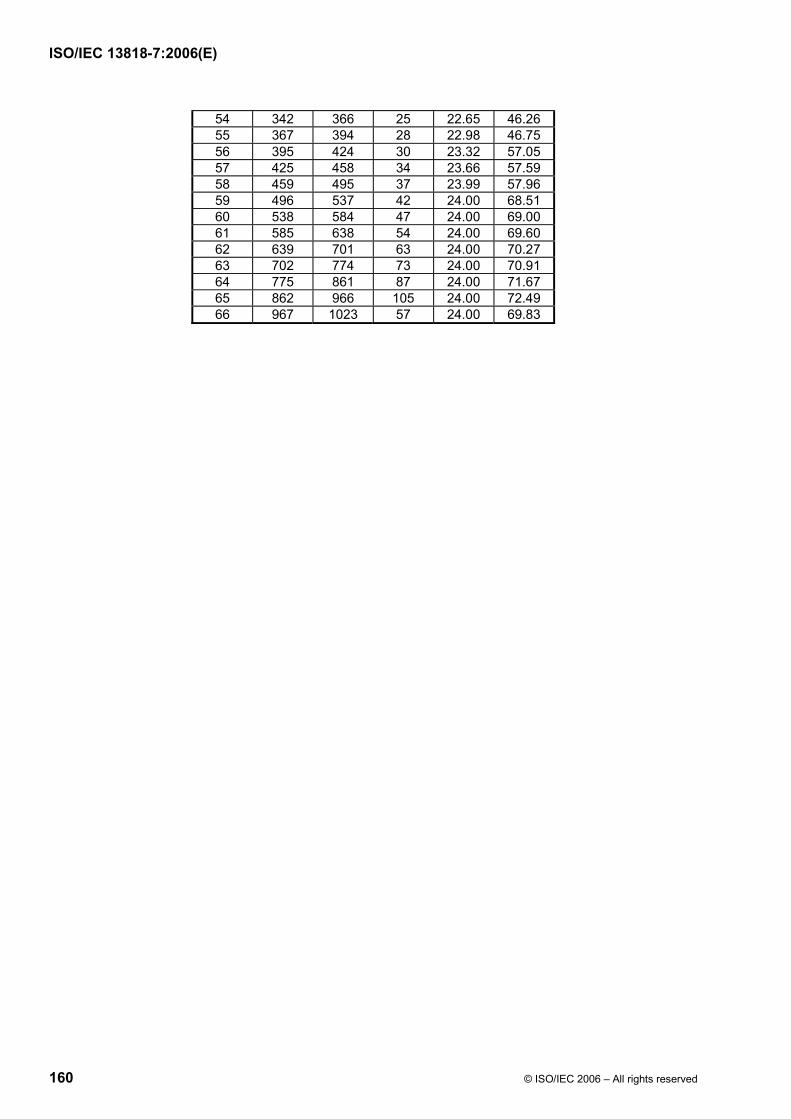
ISO/IEC 13818-7:2006(E)
160 © ISO/IEC 2006 – All rights reserved
54 342 366 25 22.65 46.26 55 367 394 28 22.98 46.75 56 395 424 30 23.32 57.05 57 425 458 34 23.66 57.59 58 459 495 37 23.99 57.96 59 496 537 42 24.00 68.51 60 538 584 47 24.00 69.00 61 585 638 54 24.00 69.60 62 639 701 63 24.00 70.27 63 702 774 73 24.00 70.91 64 775 861 87 24.00 71.67 65 862 966 105 24.00 72.49 66 967 1023 57 24.00 69.83

ISO/IEC 13818-7:2006(E)
© ISO/IEC 2006 – All rights reserved 161
Table C.20 – Psychoacoustic parameters for 64 kHz short FFT
index w_low w_high width bval qsthr 0 0 0 1 0.00 27.28 1 1 1 1 2.50 19.28 2 2 2 1 4.85 12.28 3 3 3 1 6.93 12.28 4 4 4 1 8.70 12.28 5 5 5 1 10.20 12.28 6 6 6 1 11.45 12.28 7 7 7 1 12.50 12.28 8 8 8 1 13.39 12.28 9 9 9 1 14.15 12.28 10 10 10 1 14.81 12.28 11 11 11 1 15.39 12.28 12 12 12 1 15.90 12.28 13 13 13 1 16.36 12.28 14 14 14 1 16.78 12.28 15 15 15 1 17.16 12.28 16 16 17 2 17.82 15.29 17 18 19 2 18.40 15.29 18 20 21 2 18.92 15.29 19 22 23 2 19.39 15.29 20 24 25 2 19.82 15.29 21 26 27 2 20.21 18.29 22 28 29 2 20.57 18.29 23 30 32 3 20.98 20.05 24 33 35 3 21.43 22.05 25 36 38 3 21.84 22.05 26 39 41 3 22.22 27.05 27 42 45 4 22.61 28.30 28 46 49 4 23.02 38.30 29 50 53 4 23.39 38.30 30 54 58 5 23.75 39.27 31 59 63 5 24.00 49.27 32 64 69 6 24.00 50.06 33 70 76 7 24.00 50.73 34 77 84 8 24.00 51.31 35 85 93 9 24.00 51.82 36 94 104 11 24.00 52.69 37 105 117 13 24.00 53.42 38 118 127 10 24.00 52.28

ISO/IEC 13818-7:2006(E)
162 © ISO/IEC 2006 – All rights reserved
Table C.21 — Psychoacoustic parameters for 88.2 kHz long FFT
index w_low w_high width bval qsthr 0 0 0 1 0.00 37.28 1 1 1 1 0.44 37.28 2 2 2 1 0.87 37.28 3 3 3 1 1.30 32.28 4 4 4 1 1.73 32.28 5 5 5 1 2.16 29.28 6 6 6 1 2.58 29.28 7 7 7 1 3.00 24.28 8 8 8 1 3.41 24.28 9 9 9 1 3.82 24.28 10 10 10 1 4.22 22.28 11 11 11 1 4.61 22.28 12 12 12 1 4.99 22.28 13 13 13 1 5.37 22.28 14 14 14 1 5.74 22.28 15 15 15 1 6.10 22.28 16 16 16 1 6.45 22.28 17 17 17 1 6.79 22.28 18 18 19 2 7.44 25.29 19 20 21 2 8.05 25.29 20 22 23 2 8.64 25.29 21 24 25 2 9.19 25.29 22 26 27 2 9.70 25.29 23 28 29 2 10.19 25.29 24 30 31 2 10.65 25.29 25 32 33 2 11.08 25.29 26 34 35 2 11.48 25.29 27 36 37 2 11.86 25.29 28 38 39 2 12.22 25.29 29 40 42 3 12.64 27.05 30 43 45 3 13.10 27.05 31 46 48 3 13.53 27.05 32 49 51 3 13.93 27.05 33 52 54 3 14.30 27.05 34 55 58 4 14.69 28.30 35 59 62 4 15.11 28.30 36 63 66 4 15.49 28.30 37 67 70 4 15.84 28.30 38 71 75 5 16.21 29.27 39 76 80 5 16.58 29.27 40 81 85 5 16.92 29.27 41 86 91 6 17.27 30.06 42 92 97 6 17.62 30.06 43 98 104 7 17.97 30.73 44 105 111 7 18.32 30.73 45 112 119 8 18.67 31.31 46 120 127 8 19.02 31.31 47 128 136 9 19.35 31.82 48 137 146 10 19.71 32.28 49 147 156 10 20.05 35.28 50 157 167 11 20.39 35.69 51 168 179 12 20.73 36.07 52 180 192 13 21.08 38.42 53 193 206 14 21.43 38.74

ISO/IEC 13818-7:2006(E)
© ISO/IEC 2006 – All rights reserved 163
54 207 221 15 21.77 39.04 55 222 237 16 22.11 44.32 56 238 255 18 22.45 44.83 57 256 274 19 22.80 45.06 58 275 295 21 23.13 55.50 59 296 318 23 23.47 55.89 60 319 344 26 23.81 56.43 61 345 373 29 24.00 66.90 62 374 405 32 24.00 67.33 63 406 442 37 24.00 67.96 64 443 484 42 24.00 68.51 65 485 533 49 24.00 69.18 66 534 591 58 24.00 69.91 67 592 660 69 24.00 70.66 68 661 745 85 24.00 71.57 69 746 851 106 24.00 72.53 70 852 988 137 24.00 73.64 71 989 1023 35 24.00 67.72

ISO/IEC 13818-7:2006(E)
164 © ISO/IEC 2006 – All rights reserved
Table C.22 — Psychoacoustic parameters for 88.2 kHz short FFT
index w_low w_high width bval qsthr 0 0 0 1 0.00 27.28 1 1 1 1 3.41 14.28 2 2 2 1 6.45 12.28 3 3 3 1 8.92 12.28 4 4 4 1 10.87 12.28 5 5 5 1 12.39 12.28 6 6 6 1 13.61 12.28 7 7 7 1 14.59 12.28 8 8 8 1 15.40 12.28 9 9 9 1 16.09 12.28 10 10 10 1 16.69 12.28 11 11 11 1 17.21 12.28 12 12 12 1 17.68 12.28 13 13 13 1 18.11 12.28 14 14 14 1 18.49 12.28 15 15 15 1 18.85 12.28 16 16 17 2 19.48 15.29 17 18 19 2 20.05 18.29 18 20 21 2 20.55 18.29 19 22 23 2 21.01 20.29 20 24 25 2 21.43 20.29 21 26 27 2 21.81 20.29 22 28 29 2 22.15 25.29 23 30 32 3 22.55 27.05 24 33 35 3 22.98 27.05 25 36 38 3 23.36 37.05 26 39 42 4 23.75 38.30 27 43 46 4 24.00 48.30 28 47 51 5 24.00 49.27 29 52 56 5 24.00 49.27 30 57 62 6 24.00 50.06 31 63 69 7 24.00 50.73 32 70 77 8 24.00 51.31 33 78 87 10 24.00 52.28 34 88 99 12 24.00 53.07 35 100 115 16 24.00 54.32 36 116 127 12 24.00 53.07

ISO/IEC 13818-7:2006(E)
© ISO/IEC 2006 – All rights reserved 165
Table C.23 — Psychoacoustic parameters for 96 kHz long FFT
index w_low w_high width bval qsthr 0 0 0 1 0.00 37.28 1 1 1 1 0.47 37.28 2 2 2 1 0.95 37.28 3 3 3 1 1.42 32.28 4 4 4 1 1.88 32.28 5 5 5 1 2.35 29.28 6 6 6 1 2.81 29.28 7 7 7 1 3.26 24.28 8 8 8 1 3.70 24.28 9 9 9 1 4.14 22.28 10 10 10 1 4.57 22.28 11 11 11 1 4.98 22.28 12 12 12 1 5.39 22.28 13 13 13 1 5.79 22.28 14 14 14 1 6.18 22.28 15 15 15 1 6.56 22.28 16 16 16 1 6.93 22.28 17 17 17 1 7.28 22.28 18 18 18 1 7.63 22.28 19 19 20 2 8.28 25.29 20 21 22 2 8.90 25.29 21 23 24 2 9.48 25.29 22 25 26 2 10.02 25.29 23 27 28 2 10.53 25.29 24 29 30 2 11.00 25.29 25 31 32 2 11.45 25.29 26 33 34 2 11.86 25.29 27 35 36 2 12.25 25.29 28 37 38 2 12.62 25.29 29 39 40 2 12.96 25.29 30 41 43 3 13.36 27.05 31 44 46 3 13.80 27.05 32 47 49 3 14.21 27.05 33 50 52 3 14.59 27.05 34 53 55 3 14.94 27.05 35 56 59 4 15.32 28.30 36 60 63 4 15.71 28.30 37 64 67 4 16.08 28.30 38 68 72 5 16.45 29.27 39 73 77 5 16.83 29.27 40 78 82 5 17.19 29.27 41 83 88 6 17.54 30.06 42 89 94 6 17.90 30.06 43 95 101 7 18.26 30.73 44 102 108 7 18.62 30.73 45 109 116 8 18.97 31.31 46 117 124 8 19.32 31.31 47 125 133 9 19.67 31.82 48 134 143 10 20.03 35.28 49 144 153 10 20.38 35.28 50 154 164 11 20.72 35.69 51 165 176 12 21.07 38.07 52 177 189 13 21.42 38.42 53 190 203 14 21.77 38.74

ISO/IEC 13818-7:2006(E)
166 © ISO/IEC 2006 – All rights reserved
54 204 218 15 22.12 44.04 55 219 234 16 22.46 44.32 56 235 252 18 22.80 44.83 57 253 271 19 23.14 55.06 58 272 292 21 23.47 55.50 59 293 316 24 23.81 56.08 60 317 342 26 24.00 66.43 61 343 372 30 24.00 67.05 62 373 406 34 24.00 67.59 63 407 445 39 24.00 68.19 64 446 490 45 24.00 68.81 65 491 543 53 24.00 69.52 66 544 607 64 24.00 70.34 67 608 685 78 24.00 71.20 68 686 783 98 24.00 72.19 69 784 910 127 24.00 73.31 70 911 1023 113 24.00 72.81

ISO/IEC 13818-7:2006(E)
© ISO/IEC 2006 – All rights reserved 167
Table C.24 — Psychoacoustic parameters for 96 kHz short FFT
index w_low w_high width bval qsthr 0 0 0 1 0.00 27.28 1 1 1 1 3.70 14.28 2 2 2 1 6.93 12.28 3 3 3 1 9.49 12.28 4 4 4 1 11.45 12.28 5 5 5 1 12.96 12.28 6 6 6 1 14.15 12.28 7 7 7 1 15.11 12.28 8 8 8 1 15.90 12.28 9 9 9 1 16.57 12.28 10 10 10 1 17.16 12.28 11 11 11 1 17.67 12.28 12 12 12 1 18.13 12.28 13 13 13 1 18.55 12.28 14 14 14 1 18.93 12.28 15 15 16 2 19.60 15.29 16 17 18 2 20.20 18.29 17 19 20 2 20.73 18.29 18 21 22 2 21.21 20.29 19 23 24 2 21.64 20.29 20 25 26 2 22.03 25.29 21 27 28 2 22.39 25.29 22 29 31 3 22.79 27.05 23 32 34 3 23.23 37.05 24 35 37 3 23.62 37.05 25 38 41 4 24.00 48.30 26 42 45 4 24.00 48.30 27 46 50 5 24.00 49.27 28 51 55 5 24.00 49.27 29 56 61 6 24.00 50.06 30 62 68 7 24.00 50.73 31 69 77 9 24.00 51.82 32 78 88 11 24.00 52.69 33 89 102 14 24.00 53.74 34 103 120 18 24.00 54.83 35 121 127 7 24.00 50.73
C.2 Gain Control
C.2.1 Encoding Process
The gain control tool consists of a PQF (Polyphase Quadrature Filter), gain detectors and gain modifiers. This tool receives the input time-domain signals and window_sequence, and then outputs gain_control_data and a gain controlled signal whose length is equal to the length of the MDCT window. The block diagram for the gain control tool is shown in Figure C.2 .
Due to the characteristics of the PQF filterbank, the order of the MDCT coefficients in each even PQF band needs to be reversed. This is done by reversing the spectral order of the MDCT coefficients, i.e. exchanging the higher frequency MDCT coefficients with the lower frequency MDCT coefficients.
If the gain control tool is used, the configuration of the filterbank tool is changed as follows. In the case of an EIGHT_SHORT_SEQUENCE window_sequence, the number of coefficients for the MDCT is 32 instead of

ISO/IEC 13818-7:2006(E)
168 © ISO/IEC 2006 – All rights reserved
128 and eight MDCTs are carried out. In the case of other window_sequence values, the number of coefficients for the MDCT is 256 instead of 1024 and one MDCT is carried out. In all cases, the filter bank tool receives a total of 2048 gain controlled signal values per frame, because the input samples have been overlapped.
C.2.1.1 PQF
The input signal is divided by a PQF into four equal width frequency bands. The coefficients of each band PQF are given as follows.
( ) ( )( ) ( ) 30,950,16
5212cos41
≤≤≤≤⎟⎠⎞
⎜⎝⎛ ++
= innQninhiπ
where
( ) ( ) 9548,95 ≤≤−= nnQnQ
and the values of Q(n) are the same values as those of the decoder.
C.2.1.2 Gain Detector
The gain detectors produce gain control data which satisfies the bitstream syntax. This information consists of the number of gain changes, the index of gain change positions and the index of gain change level. Note that the output gain control data applies to the previous input time signal. This means that the gain detector has a one frame delay.
The detection of the gain change point is done in the second half of the MDCT window region and in the non-overlapped region (of LONG_START_SEQUENCE and LONG_STOP_SEQUENCE). Thus the number of regions are one for ONLY_LONG_SEQUENCE, two for LONG_START_SEQUENCE and LONG_STOP_SEQUNCE, and eight for EIGHT_SHORT_SEQUENCE.
The samples in each region are divided into subregions, each having eight-tuple samples. Then one value (e.g. peak value of samples) is selected in these subregions. The ratios between the values of subregions and the value of the last subregion are calculated. If the ratio is greater or less than the value of 2 ^ n where n is an integer between -4 to 11, those subregions can be detected as the gain change points of the signals. The subregion number which is detected as the gain change point is set to be the position data. The exponent of the ratio is set to be the gain data. The time resolution of the gain control is approximately 0.7 ms at 48 kHz sampling rate.
C.2.1.3 Gain Modifier
The gain modifier for each PQF band controls the gain of each signal band. The complementary gain control process in the decoder decreases the pre-echo and reconstructs the original signal. A window function for gain control, the Gain Modification Function (GMF), which is defined in the decoding process, is derived from the gains and the gain-changed positions. The gain controlled signals are derived by applying the GMF to the corresponding band signals.
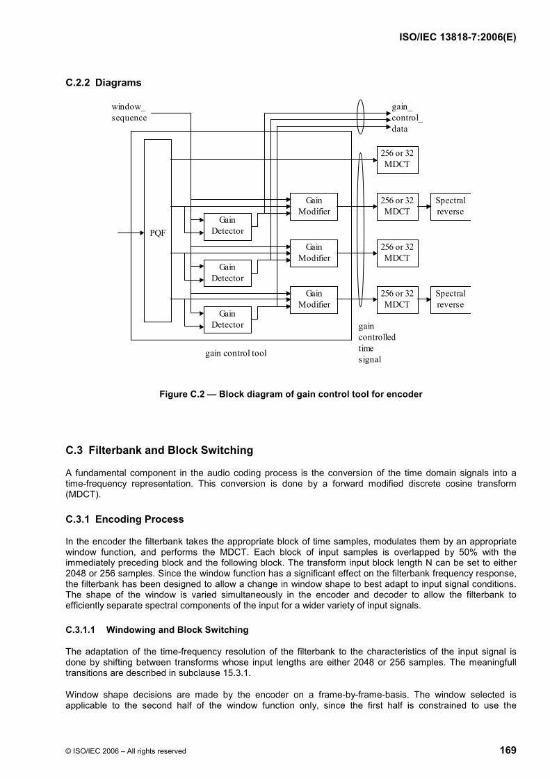
ISO/IEC 13818-7:2006(E)
© ISO/IEC 2006 – All rights reserved 169
C.2.2 Diagrams
PQF
gain_ control_ data
gain control tool
window_ sequence
Gain Modifier
Gain Detector
Gain Modifier
Gain Detector
Gain Modifier
Gain Detector gain
controlled time signal
256 or 32 MDCT
256 or 32 MDCT
256 or 32 MDCT
256 or 32 MDCT
Spectral reverse
Spectral reverse
Figure C.2 — Block diagram of gain control tool for encoder
C.3 Filterbank and Block Switching
A fundamental component in the audio coding process is the conversion of the time domain signals into a time-frequency representation. This conversion is done by a forward modified discrete cosine transform (MDCT).
C.3.1 Encoding Process
In the encoder the filterbank takes the appropriate block of time samples, modulates them by an appropriate window function, and performs the MDCT. Each block of input samples is overlapped by 50% with the immediately preceding block and the following block. The transform input block length N can be set to either 2048 or 256 samples. Since the window function has a significant effect on the filterbank frequency response, the filterbank has been designed to allow a change in window shape to best adapt to input signal conditions. The shape of the window is varied simultaneously in the encoder and decoder to allow the filterbank to efficiently separate spectral components of the input for a wider variety of input signals.
C.3.1.1 Windowing and Block Switching
The adaptation of the time-frequency resolution of the filterbank to the characteristics of the input signal is done by shifting between transforms whose input lengths are either 2048 or 256 samples. The meaningfull transitions are described in subclause 15.3.1.
Window shape decisions are made by the encoder on a frame-by-frame-basis. The window selected is applicable to the second half of the window function only, since the first half is constrained to use the

ISO/IEC 13818-7:2006(E)
170 © ISO/IEC 2006 – All rights reserved
appropriate window shape from the preceding frame. Figure C.3 shows the sequence of blocks for the transition (D-E-F) to and from a frame employing the sine function window. The window shape selector generally produces window shape run-lengths greater than that shown in the figure.
The 2048 time-domain values x’i,n to be windowed are the last 1024 values of the previous window_sequence concatenated with 1024 values of the current block. The formula below shows this fact:
⎩⎨⎧
<≤<≤
= +−
2048n1024for , 1024n0for ,
',
)1024(),1(,
ni
nini x
xx
Where i is the block index and n is the sample index within a block. Once the window shape is selected, the window_shape syntax element is initialized. Together with the chosen window_sequence all information needed for windowing exist.
With the window halves described in subclause 15.3.2, all window_sequence's can be assembled.
C.3.1.2 MDCT
The spectral coefficient, Xi,k, are defined as follows:
( )∑−
=⎟⎟⎠
⎞⎜⎜⎝
⎛⎟⎠⎞
⎜⎝⎛ ++⋅=
1
00,, 2
12cos2N
nniki knn
NzX π
for 2/0 Nk <≤ .
1)/2(N/2 = n
valuequence window_seon the based window transformone theoflength window= N
indexblock = i
indext coefficien spectral =k
index sample =n
sequenceinput windowedinz
:where
0+
=
The analysis window length N of one transform window of the mdct is a function of the syntax element window_sequence and is defined as follows:
⎪⎪⎩
⎪⎪⎨
⎧
(0x3) SEQUENCELONG_STOP_ if 2048, times)(8 (0x2) T_SEQUENCEEIGHT_SHOR if 256,
(0x1) _SEQUENCELONG_START if 2048, (0x0) SEQUENCEONLY_LONG_ if 2048,
=N
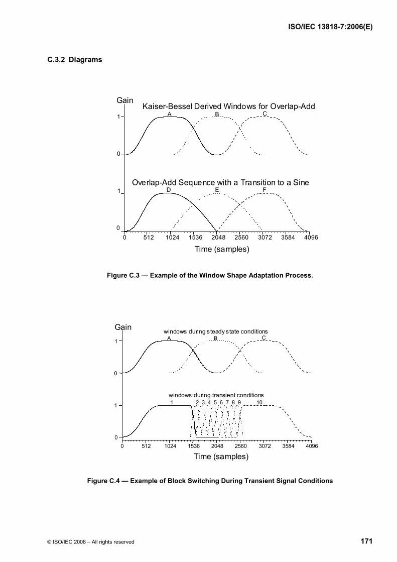
ISO/IEC 13818-7:2006(E)
© ISO/IEC 2006 – All rights reserved 171
C.3.2 Diagrams
0 512 1024 1536 2048 2560 3072 3584 4096
FED Overlap-Add Sequence with a Transition to a Sine
1
1
0
0
CBA Kaiser-Bessel Derived Windows for Overlap-Add
Gain
Time (samples)
Figure C.3 — Example of the Window Shape Adaptation Process.
0 512 1024 1536 2048 2560 3072 3584 4096
1
1
0
0
102 3 4 5 6 7 8 91
CBA
windows during transient conditions
windows during steady state conditionsGain
Time (samples)
Figure C.4 — Example of Block Switching During Transient Signal Conditions
ISO/IEC 13818-7:2006(E)
172 © ISO/IEC 2006 – All rights reserved
C.4 Prediction
C.4.1 Tool Description
Since each predictor itself is identical on both, the encoder and decoder side, all descriptions and definitions as specified for the decoder in clause 13 are also valid here.
Prediction is used for an improved redundancy reduction and is especially effective in case of more or less stationary parts of a signal which belong to the most demanding parts in terms of required bitrate. Prediction can be applied to every channel using an intra channel (or mono) predictor which exploits the auto-correlation between the spectral components of consecutive frames. Because a window_sequence of type EIGHT_SHORT_SEQUENCE indicates signal changes, i.e. non-stationary signal characteristic, prediction is only used if window_sequence is of type ONLY_LONG_SEQUENCE, LONG_START_SEQUENCE or LONG_STOP_SEQUENCE.
For each channel prediction is applied to the spectral components resulting from the spectral decomposition of the filterbank. For each spectral component up to limit specified by PRED_SFB_MAX, there is one corresponding predictor resulting in a bank of predictors, where each predictor exploits the auto-correlation between the spectral component values of consecutive frames.
The overall coding structure using a filterbank with high spectral resolution implies the use of backward adaptive predictors to achieve high coding efficiency. In this case, the predictor coefficients are calculated from preceding quantized spectral components in the encoder as well as in the decoder and no additional side information is needed for the transmission of predictor coefficients - as would be required for forward adaptive predictors. A second order backward-adaptive lattice structure predictor is used for each spectral component, so that each predictor is working on the spectral component values of the two preceding frames. The predictor parameters are adapted to the current signal statistics on a frame by frame base, using an LMS based adaptation algorithm. If prediction is activated, the quantizer is fed with a prediction error instead of the original spectral component, resulting in a coding gain.
C.4.2 Encoding Process
For each spectral component up to the limit specified by PRED_SFB_MAX of each channel there is one predictor. The following description is valid for one single predictor and has to be applied to each predictor. As said above, each predictor is identical on both, the encoder and decoder side. Therefore, the predictor structure is the same as shown in Figure 4 and the calculations of the estimate xest(n) of the current spectral component x(n) as well as the calculation and adaptation of the predictor coefficients are exactly the same as those described for the decoder in subclause 8.3.2.
The only difference on the encoder side is that the prediction error has to be calculated according to
)()()( nxnxne est−=
to be fed to the quantizer. In this case the quantized prediction error is transmitted instead of the quantized spectral component.
C.4.2.1 Predictor Control
In order to guarantee that prediction is only used if this results in a coding gain, an appropriate predictor control is required and a small amount of predictor control information has to be transmitted to the decoder. For the predictor control, the predictors are grouped into scalefactor bands.
The following description is valid for either one single_channel_element() or one channel_pair_element() and has to be applied to each such element. Since prediction is only used if window_sequence is of type ONLY_LONG_SEQUENCE, LONG_START_SEQUENCE or LONG_STOP_SEQUENCE for the channel associated with the single_channel_element() or for both channels associated with the channel_pair_element(), the following applies only in these cases.

ISO/IEC 13818-7:2006(E)
© ISO/IEC 2006 – All rights reserved 173
The predictor control information for each frame, which has to be transmitted as side information, is determined in two steps. First, it is determined for each scalefactor band whether or not prediction leads to a coding gain and if yes, the prediction_used bit for that scalefactor band is set to one. After this has been done for all scalefactor bands up to PRED_SFB_MAX, it is determined whether the overall coding gain by prediction in this frame compensates at least the additional bit need for the predictor side information. If yes, the predictor_data_present bit is set to 1, the complete side information including that needed for predictor reset (see below) has to be transmitted and the prediction error value is fed to the quantizer. Otherwise, the predictor_data_present bit is set to 0, the prediction_used bits are all reset to zero and are not transmitted. In this case, the spectral component value is fed to the quantizer. Figure C.5 shows a block diagram of the prediction unit for one scalefactor band. As described above, the predictor control first operates on all predictors of one scalefactor band and is then followed by a second step over all scalefactor bands.
In case of a single_channel_element() or a channel_pair_element() with common_window = 0 the control information is calculated and valid for the predictor bank(s) of the channel(s) associated with that element. In case of a channel_pair_element() with common_window = 1 the control information is calculated considering both channels associated with that element together. In this case the control information is valid for both predictor banks of the two channels in common.
C.4.2.2 Reconstruction of the Quantized Spectral Component
Since the reconstructed value of the quantized spectral component is needed as predictor input signal, it has to be calculated in the encoder, see also Figure 8 and Figure C.5. Depending on the value of the prediction_used bit, the reconstructed value is either the quantized spectral component or the quantized prediction error. Therefore, the following steps are necessary:
• If the bit is set (1), then the quantized prediction error, reconstructed from data to be transmitted, is added to the estimate xest(n), calculated by the predictor, resulting in the reconstructed value of the quantized spectral component, i.e. )()()( nenxnx qestrec +=
• If the bit is not set (0), then the quantized value of the spectral component is identical to the value reconstructed directly from the data to be transmitted.

ISO/IEC 13818-7:2006(E)
174 © ISO/IEC 2006 – All rights reserved
C.4.3 Diagrams
REC
PREDICTOR CONTROL (P_ON/P_OFF)
IF (P_ON) yj(n) = ej(n) = xj(n) - xj,est(n) IF (P_OFF) yj(n) = xj(n)
Pi xi (n)
xi,est (n)
xi,rec (n-1)
Qi yi (n) yi,q (n)
Predictor Side Info
Pk xk (n)
xk,est (n)
xk,rec (n-1)
Qk yk (n) yk,q (n)
Figure C.5 — Block diagram of prediction unit for one scalefactor band. The complete processing is only shown for predictor Pi (Q - quantizer, REC - reconstruction of last quantized value). Note that the
predictor control operates on all predictors Pi ... Pj ... Pk of a scalefactor band and is followed by a second control over all scalefactor bands.
C.5 Temporal Noise Shaping (TNS)
Temporal Noise Shaping is used to control the temporal shape of the quantization noise within each window of the transform. This is done by applying a filtering process to parts of the spectral data of each channel.
Encoding is done on a window basis. The following steps are carried out to apply the Temporal Noise Shaping tool to one window of spectral data:
• A target frequency range for the TNS tool is chosen. A suitable choice is to cover a frequency range from 1.5 kHz to the uppermost possible scalefactor band with one filter. Please note that this parameter (TNS_MAX_BANDS) depends on profile and sampling rate as indicated in the normative part.
• Next, a linear predictive coding (LPC) calculation is carried out on the spectral MDCT coefficients corresponding to the chosen target frequency range. For better stability, coefficients corresponding to frequencies below 2.5 kHz may be excluded from this process. Standard LPC procedures as known from speech processing can be used for the LPC calculation, e.g. the well-known Levinson-Durbin algorithm. The calculation is carried out for the maximum permitted order of the noise shaping filter (TNS_MAX_ORDER). Please note that this value depends on the profile as indicated in the normative part.

ISO/IEC 13818-7:2006(E)
© ISO/IEC 2006 – All rights reserved 175
• As a result of the LPC calculation, the expected prediction gain gp is known as well as the TNS_MAX_ORDER reflection coefficients r[] (so-called PARCOR coefficients).
• If the prediction gain gp does not exceed a certain threshold t, no temporal noise shaping is used. In this case, the tns_data_present bit is set to zero and TNS processing is finished. A suitable threshold value is t = 1.4.
• If the prediction gain gp exceeds the threshold t, temporal noise shaping is used.
• In a next step the reflection coefficients are quantized using coef_res bits. An appropriate choice for coef_res is 4 bits. The following pseudo code describes the conversion of the reflection coefficients r[] to index values index[] and back to quantized reflection coefficients rq[].
iqfac = ((1 << (coef_res-1)) - 0.5) / (π/2.0); iqfac_m = ((1 << (coef_res-1)) + 0.5) / (π/2.0); /* Reflection coefficient quantization */ for (i = 0; i < TNS_MAX_ORDER; i++) { index[i] = NINT(arcsin( r[i] ) * ((r[i] >= 0) ? iqfac : iqfac_m)); } /* Inverse quantization */ for (i = 0; i < TNS_MAX_ORDER; i++) { rq[i] = sin( index[i] / ((index[i] >= 0) ? iqfac : iqfac_m) ); }
where arcsin() denotes the inverse sin() function.
• The order of the used noise shaping filter is determined by subsequently removing all reflection coefficients with an absolute value smaller than a threshold p from the "tail" of the reflection coefficient array. The number of the remaining reflection coefficients is the order of the noise shaping filter. A suitable threshold for truncation is p = 0.1.
• The remaining reflection coefficients rq[] are converted into order+1 linear prediction coefficients a[] (known as "step-up procedure"). A description of this procedure is provided in the normative part as a part of the tool description (see "/* Conversion to LPC coefficients */").
• The computed LPC coefficients a[] are used as the encoder noise shaping filter coefficients. This FIR filter is slid across the specified target frequency range exactly the way it is described in the normative part for the decoding process (tool description). The difference between the decoding and encoding filtering is that the all-pole (auto-regressive) filter used for decoding is replaced by its inverse all-zero (moving-average) filter, i.e. replacing the decoder filter equation
y[n] = x[n] - a[1]*y[n-1] - ... - a[order]*y[n-order] by the inverse (encoder) filter equation
y[n] = x[n] + a[1]*x[n-1] + ... + a[order]*x[n-order] By default, an upward direction of the filtering is appropriate.
• Finally, the side information for Temporal Noise Shaping is transmitted:
Table C.25 — TNS side information
Data Element Algorithmic Variable or Value n_filt 1 coef_res coef_res-3 coef_compress 0 length Number of processed scalefactor bands direction 0 (upwards) order Order of noise shaping filter coef[] index[]

ISO/IEC 13818-7:2006(E)
176 © ISO/IEC 2006 – All rights reserved
Optionally, the use of the coef_compress field allows saving 1 bit per transmitted reflection coefficient if none of the reflection coefficients use more than half of their full range. Specifically, if the two most significant bits of each quantized reflection coefficient are either ‘00’ or ‘11’, coeff_compress may be set to a value of one and the size of the transmitted quantized reflection coefficients decreased by one.
C.6 Joint Coding
C.6.1 M/S Stereo
The decison to code left and right coefficients as either left + right (L/R) or mid/side (M/S) is made on a noiseless coding band by noiseless coding band basis for all spectral coefficients in the current block. For each noiseless coding band the following decison process is used:
1. For each noiseless coding band, not only L and R raw thresholds, but also M = (L+R)/2 and S = (L-R)/2 raw thresholds are calculated. For the raw M and S thresholds, rather than using the tonality for the M or S threshold, one uses the more tonal value from the L or R calculation in each threshold calculation band, and proceed with the psychoacoustic model for M and S from the M and S energies and the minimum of the L or R values for C(ω) in each threshold calculation band. The values that are provided to the imaging control process are identified in the psychoacoustic model information section as en(b) (the spread normalized energy) and nb(b), the raw threshold.
2. The raw thresholds for M, S, L and R, and the spread energy for M, S, L and R, are all brought into an “imaging control process”. The resulting adjusted thresholds are inserted as the values for cb(b) into step 11 of the psychoacoustic model for further processing.
3. The final, protected and adapted to coder-band thresholds for all of M,S,L and R are directly applied to the appropriate spectrum by quantizing the actual L, R, M and S spectral values with the appropriate calculated and quantized threshold.
4. The number of bits actually required to code M/S, and the number of bits required to code L/R are calculated.
5. The method that uses the least bits is used in each given noiseless coding band, and the stereo mask is set accordingly.
With these definitions
Mthr,Sthr,Rthr, Lthr raw thresholds. (the nb(b) from step 10 of the psychoacoustic model)
Mengy,Sengy,Rengy,Sengy spread energy.(en(b) from step 6 of the psychoacoustic model)
Mfthr, Sfthr, Rfthr, Lfthr final (output) thresholds. (returned as nb(b) in step 11 of the psychoacoustic model)
bmax(b) BMLD protection ratio, as can be calculated from
min( ( ), 15.5)3 0.5 0.5 cos
15.5( ) 10bval b
bmax b π⎡ ⎤⎛ ⎞− ⋅ + ⋅ ⋅⎢ ⎥⎜ ⎟
⎝ ⎠⎣ ⎦=
the imaging control process for each noiseless coding band is as follows:
t = Mthr/Sthr
if (t > 1)
t = 1/t
Rfthr = max(Rthr*t, min (Rthr, bmax*Rengy)

ISO/IEC 13818-7:2006(E)
© ISO/IEC 2006 – All rights reserved 177
Lfthr = max(Lthr*t, min (Lthr, bmax) *Lengy)
t = min(Lthr, Rthr)
Mfthr = min(t, max(Mthr, min(Sengy*bmax,Sthr))
Sfthr = min(t, max(Sthr, min(Mengy*bmax,Mthr))
C.6.2 Intensity Stereo Coding
Intensity stereo coding is used to exploit irrelevance in the between both channels of a channel pair in the high frequency region. The following procedure describes one possible implementation while several different implementations are possible within the framework of the defined bitstream syntax.
Encoding is done on a window group basis. The following steps are carried out to apply the intensity stereo coding tool to one window group of spectral data:
• A suitable approach is to code a consecutive region of scalefactor bands in intensity stereo technique starting above a lower border frequency f0. An average value of f0 = 6 kHz is appropriate for most types of signals.
• For each scalefactor band, the energy of the left, right and the sum channel is calculated by summing the squared spectral coefficients, resulting in values El[sfb], Er[sfb], Es[sfb]. If the window group comprises several windows, the energies of the included windows are added.
• For each scalefactor band, the corresponding intensity position value is computed as
⎟⎟⎠
⎞⎜⎜⎝
⎛⎟⎟⎠
⎞⎜⎜⎝
⎛⋅=
][][
log2 ][_ 2 sfbEsfbE
NINTsfbpositionisr
l
• Next, the intensity signal spectral coefficients speci[i] are calculated for each scalefactor bands by adding spectral samples from the left and right channel (specl[i] and specr[i]) and rescaling the resulting values like
][][
])[][(][sfbEsfbE
ispecispecispecs
lrli ⋅+=
• The intensity signal spectral components are used to replace the corresponding left channel spectral coefficients. The corresponding spectral coefficients of the right channel are set to zero.
Then, the standard process for quantization and encoding is performed on the spectral data of both channels. However, the prediction status of the right channel predictors is forced to "off" for the scalefactor bands coded in intensity stereo. These predictors are updated by using an intensity decoded version of the quantized spectral coefficients. The procedure for this is described in the tool description for the intensity stereo decoding process in the normative part.
Finally, before transmission the Huffman codebook INTENSITY_HCB (15) is set in the sectioning information for all scalefactor bands that are coded in intensity stereo.

ISO/IEC 13818-7:2006(E)
178 © ISO/IEC 2006 – All rights reserved
C.7 Quantization
C.7.1 Introduction
The description of the AAC quantization module is subdivided into three levels. The top level is called "loops frame program". The loops frame program calls a subroutine named "outer iteration loop" which calls the subroutine "inner iteration loop". For each level a corresponding flow diagram is shown.
The loops module quantizes an input vector of spectral data in an iterative process according to several demands. The inner loop quantizes the input vector and increases the quantizer step size until the output vector can be coded with the available number of bits. After completion of the inner loop an outer loop checks the distortion of each scalefactor band and, if the allowed distortion is exceeded, attenuates the scalefactor band and calls the inner loop again.
AAC loops module input:
1. vector of the magnitudes of the spectral values mdct_line(0..1023).
2. xmin(sb) (see subclause C.1.4, step 0)
3. mean_bits (average number of bits available for encoding the bitstream).
4. more_bits, the number of bits in addition to the average number of bits, calculated by the psychoacoustic module out of the perceptual entropy (PE).
5. the number and width of the scalefactor bands (see Table 45 to Table 57)
6. for short block grouping the spectral values have to be interleaved so that spectral lines that belong to the same scalefactor band but to different block types which shall be quantized with the same scalefactors are put together in one (bigger) scalefactor band (for a full description of grouping see subclause 8.3.4)
AAC loops module output:
1. vector of quantized values x_quant(0..1023).
2. a scalefactor for each scalefactor band (sb)
3. common_scalefac (quantizer step size information for all scalefactor bands)
4. number of unused bits available for later use.
C.7.2 Preparatory Steps
C.7.2.1 Reset of all Iteration Variables
1. The start value of common_scalefac for the quantizer is calculated so that all quantized MDCT values can be encoded in the bitstream :
start_common_scalefac = ceiling(16/3*(log2( (max_mdct_line ^ (3/4) )/MAX_QUANT)))
max_mdct_line is the largest absolute MDCT coefficient and ceiling() is the function which rounds to the nearest integer in the direction of positive infinity. MAX_QUANT is the maximum quantized value which can be encoded in the bitstream, defined as 8191. During the iteration process, the common_scalefac must not become less than start_common_scalefac.
2. Scalefactor[sb] is set to zero for all values of sb.
C.7.3 Bit Reservoir Control
Bits are saved to the reservoir when fewer than the mean_bits are used to code one frame.
mean_bits = bit_rate * 1024 / sampling_rate.
ISO/IEC 13818-7:2006(E)
© ISO/IEC 2006 – All rights reserved 179
The number of bits which can be saved in the bit reservoir at maximum is called ‘max_bit_reservoir’ which is calculated using the procedure outlined in subclause 8.2.3. If the reservoir is full, unused bits have to be encoded in the bitstream as fillbits.
The maximum amount of bits available for a frame is the sum of mean_bits and bits saved in the bit reservoir.
The number of bits that should be used for encoding a frame depends on the more_bits value which is calculated by the psychoacoustic model and the maximum available bits. The simplest way to control bit reservoir is :
if more_bits > 0 : available_bits = mean_bits + min ( more_bits, bit_reservoir_state[frame]) if more_bits < 0 : available_bits = mean_bits + max ( more_bits, bit_reservoir_state[frame] - max_bit_reservoir)
C.7.4 Quantization of MDCT Coefficients
The formula for the quantization in the encoder is the inverse of the decoder dequantization formula (see also the decoder description) :
x_quant = int (( abs( mdct_line ) * (2^(- ¼ * (sf_decoder - SF_OFFSET))) )^(3/4) + MAGIC_NUMBER)
MAGIC_NUMBER is defined to 0.4054, SF_OFFSET is defined as 100 and mdct_line is one of spectral values, which is calculated from the MDCT. These values are also called ‘coefficients’. The scalefactor 'sf_decoder' is the same as 'sf[g][sfb]' defined in clause 11.
For use in the iteration loops, the scalefactor ‘sf_decoder’ is split in two variables:
sf_decoder = common_scalefac - scalefactor + SF_OFFSET
It follows from this, that the formula used in the distortion control loop is:
x_quant = int(( abs(mdct_line) * (2^(-¼ * (scalefactor - common_scalefac))) )^(3/4) + MAGIC_NUMBER)
The signs of scalefactor is such that a positive change increases the magnitude of x_quant, and so decreases the distortion and increases the number of bits used.
The sign of the mdct_line is saved separately and added again only for counting the bits and encoding the bitstream.
C.7.4.1 Outer Iteration Loop (Distortion Control Loop)
The outer iteration loop controls the quantization noise which is produced by the quantization of the frequency domain lines within the inner iteration loop. The coloring of the noise is done by multiplication of the lines within scalefactor bands with the actual scalefactors before doing the quantization. The following pseudo-code illustrates the multiplication.
do for each scalefactor band sb:
do from lower index to upper index i of scalefactor band
mdct_scaled(i) = abs(mdct_line(i))^(3/4) * 2^(3/16 * scalefactor(sb))
end do
end do
ISO/IEC 13818-7:2006(E)
180 © ISO/IEC 2006 – All rights reserved
C.7.4.2 Call of Inner Iteration Loop
For each outer iteration loop (distortion control loop) the inner iteration loop (rate control loop) is called. The parameters are the frequency domain values with the scalefactors applied to the values within the scalefactor bands (mdct_scaled(0..1023)), a start value for common_scalefac, and the number of bits which are available to the rate control loop. The result is the number of bits actually used and the quantized frequency lines x_quant(i), and a new common_scalefac.
The formula to calculate the quantized MDCT coefficients is:
x_quant(i) = int (( mdct_scaled (i) * 2^(-3/16 * common_scalefac)) + MAGIC_NUMBER)
The bits, that would be needed to encode the quantized values and the side information (scalefactors etc.) are counted according to the bitstream syntax, described in clause 9.
C.7.4.3 Attenuation of Scalefactor Bands which Violate the Masking Threshold
The calculation of the distortion (error_energy(sb)) of the scalefactor band is done as follows:
do for each scalefactor band sb: error_energy(sb)=0 do from lower index to upper index i of scalefactor band error_energy(sb) = error_energy(sb) + (abs( mdct_line(i)) - (x_quant(i) ^(4/3) * 2^(¼ * (scalefactor(sb) -common_scalefac ))))^2 end do end do All spectral values of the scalefactor bands which have a distortion that exceeds the allowed distortion (xmin(sb)) are attenuated according to formula in subclause C.7.4.1, the new scalefactors can be calculated according to this pseudocode:
do for each scalefactor band sb if ( error_energy(sb) > xmin(sb) ) then scalefactor(sb) = scalefactor(sb) - 1 end if end do
C.7.4.4 Conditions for the Termination of the Loops Processing
Normally the loops processing terminates, if there is no scalefactor band with more than the allowed distortion. However this is not always possible to obtain. In this case there are other conditions to terminate the outer loop. If
• All scalefactor bands with an energy exceeding xmin(sb) are already attenuated, or
• The difference between two consecutive scalefactors is greater than 60
The loop processing stops, and by restoring the saved scalefactors(sb) a useful output is available. For real-time implementation, there might be a third condition added which terminates the loops in case of a lack of computing time.
The procedure described above is only valid in the case the number of available bits is equal to the number of required bits corresponding to the perceptual entropy. In the case the number of available bits is higher or lower than the number of required bits, it is the objective of the loops module to create a constant ratio between the quantisation noise and the masked threshold over all scale factor bands (constant Noise to Mask Ratio (NMR)). This can be realised by applying an offset to the target allowed distortion xmin(sb), that is the same for all scale factor bands, prior to starting the loops module.

ISO/IEC 13818-7:2006(E)
© ISO/IEC 2006 – All rights reserved 181
C.7.4.5 Inner Iteration Loop (Rate Control Loop)
The inner iteration loop calculates the actual quantization of the frequency domain data (mdct_scaled) with the following function, which uses the formula from subclause C.7.4.2:
quantize_spectrum(x_quant[] , mdct_scaled[] , common_scalefac): do for all MDCT coefficients i : x_quant(i) = int ((mdct_scaled (i) * 2^(-3/16 * common_scalefac)) + MAGIC_NUMBER) end do and then calls a function bit_count(). This function counts the number of bits that would be neccessary to encode a bitstream frame according to clause 6.
The inner iteration loop can be implemented using successive approximation:
inner_loop(): if (outer_loop_count == 0) common_scalefac = start_common_scalefac; quantizer_change = 32; else quantizer_change = 1; end if do quantize_spectrum(); counted_bits = bit_count(); if (counted_bits > available_bits) then common_scalefac = common_scalefac + quantizer_change; else common_scalefac = common_scalefac - quantizer_change; end if quantizer_change = int (quantizer_change / 2) ; if (quantizer_change == 0) && (counted_bits > available_bits) quantizer_change = 1; end if while (quantizer_change != 0) Due to the choice of start_common_scalefac calculated from subclause C.7.2.1, after the first run through the inner loop the number of needed bits is usually greater than the available bits , and therefore common_scalefac will be increased by the quantizer_change.

ISO/IEC 13818-7:2006(E)
182 © ISO/IEC 2006 – All rights reserved
Calculation of available bits
Reset of iteration variables
Outer Iteration Loop
Calculate the number of unused bits
RETURN
All spectral values zero ?
ny
BEGIN
Figure C.6 — AAC iteration loop

ISO/IEC 13818-7:2006(E)
© ISO/IEC 2006 – All rights reserved 183
RETURN
n y
Inner Iteration Loop
Calculate the distortion for eachscalefactor band
Save scaling factors of the scalefactorbands
Amplify scalefactor bands with more than the allowed distortion
At least one band with more than the allowed distortion ?
Amplification of all bands below upper limit ?
All scalefactor bands amplified ?
Restore scaling factors
ny
n y
BEGIN
Figure C.7 — AAC outer iteration loop

ISO/IEC 13818-7:2006(E)
184 © ISO/IEC 2006 – All rights reserved
Quantization
change quantizer_change
count bits
quantizer_change = 0 ?
BEGIN
add quantizer_change to common_scalefac
ny
Figure C.8 — AAC inner iteration loop
C.8 Noiseless Coding
C.8.1 Introduction
In the AAC encoder the input to the noiseless coding module is the set of 1024 quantized spectral coefficients. Since the noiseless coding is done inside the quantizer inner loop, it is part of an iterative process that converges when the total bit count (of which the noiseless coding is the vast majority) is within some interval surrounding the allocated bit count. This section will describe the encoding process for a single call to the noiseless coding module.
Noiseless coding is done via the following steps:
• Spectrum clipping
• Preliminary Huffman coding using maximum number of sections
• Section merging to achieve lowest bit count
C.8.2 Spectrum Clipping
As a first step a method of noiseless dynamic range limiting may be applied to the spectrum. Up to four coefficients can be coded separately as magnitudes in excess of one, with a value of +-1 left in the quantized coefficient array to carry the sign. The index of the scalefactor band containing the lowest-frequency “clipped”

ISO/IEC 13818-7:2006(E)
© ISO/IEC 2006 – All rights reserved 185
coefficients is sent in the bitstream. Each of the “clipped” coefficients is coded as a magnitude (in excess of 1) and an offset from the base of the previously indicated scalefactor band. For this the long block scalefactor bands and coefficient ordering within those bands are used regardless of the window sequence. One strategy for applying spectrum clipping is to clip high-frequency coefficients whose absolute amplitudes are larger than one. Since the side information for carrying the clipped coefficients costs some bits, this noiseless compression is applied only if it results in a net savings of bits.
C.8.3 Sectioning
The noiseless coding segments the set of 1024 quantized spectral coefficients into sections, such that a single Huffman codebook is used to code each section (the method of Huffman coding is explained in a later section). For reasons of coding efficiency, section boundaries can only be at scalefactor band boundaries so that for each section of the spectrum one must transmit the length of the section, in scalefactor bands, and the Huffman codebook number used for the section.
Sectioning is dynamic and typically varies from block to block, such that the number of bits needed to represent the full set of quantized spectral coefficients is minimized. This is done using a greedy merge algorithm starting with the maximum possible number of sections each of which uses the Huffman codebook with the smallest possible index. Sections are merged if the resulting merged section results in a lower total bit count, with merges that yield the greatest bit count reduction done first. If the sections to be merged do not use the same Huffman codebook then the codebook with the higher index must be used.
Sections often contain only coefficients whose value is zero. For example, if the audio input is band limited to 20 kHz or lower, then the highest coefficients are zero. Such sections are coded with Huffman codebook zero, which is an escape mechanism that indicates that all coefficients are zero and it does not require that any Huffman codewords be sent for that section.
C.8.4 Grouping and Interleaving
If the window sequence is eight short windows then the set of 1024 coefficients is actually a matrix of 8 by 128 frequency coefficients representing the time-frequency evolution of the signal over the duration of the eight short windows. Although the sectioning mechanism is flexible enough to efficiently represent the 8 zero sections, grouping and interleaving provide for greater coding efficiency. As explained earlier, the coefficients associated with contiguous short windows can be grouped such that they share scalefactors amongst all scalefactor bands within the group. In addition, the coefficients within a group are interleaved by interchanging the order of scalefactor bands and windows. To be specific, assume that before interleaving the set of 1024 coefficients c are indexed as
c[g][w][b][k]
where
g is the index on groups
w is the index on windows within a group
b is the index on scalefactor bands within a window
k is the index on coefficients within a scalefactor band
and the right-most index varies most rapidly.
After interleaving the coefficients are indexed as
c[g][b][w][k]
This has the advantage of combining all zero sections due to band-limiting within each group.

ISO/IEC 13818-7:2006(E)
186 © ISO/IEC 2006 – All rights reserved
C.8.5 Scalefactors
The coded spectrum uses one quantizer per scalefactor band. The step sizes of each of these quantizers is specified as a set of scalefactors and a global gain which normalizes these scalefactors. In order to increase compression, scalefactors associated with scalefactor bands that have only zero-valued coefficients are ignored in the coding process and therefore do not have to be transmitted. Both the global gain and scalefactors are quantized in 1.5 dB steps. The global gain is coded as an 8-bit unsigned integer and the scalefactors are differentially encoded relative to the previous scalefactor (or global gain for the first scalefactor) and then Huffman coded. The dynamic range of the global gain is sufficient to represent full-scale values from a 24-bit PCM audio source.
C.8.6 Huffman Coding
Huffman coding is used to represent n-tuples of quantized coefficients, with the Huffman code drawn from one of 11 codebooks. The spectral coefficients within n-tuples are ordered (low to high) and the n-tuple size is two or four coefficients. The maximum absolute value of the quantized coefficients that can be represented by each Huffman codebook and the number of coefficients in each n-tuple for each codebook is shown in Table C.26. There are two codebooks for each maximum absolute value, with each representing a distinct probability distribution function. The best fit is always chosen. In order to save on codebook storage (an important consideration in a mass-produced decoder), most codebooks represent unsigned values. For these codebooks the magnitude of the coefficients is Huffman coded and the sign bit of each non-zero coefficient is appended to the codeword.
Table C.26 — Huffman Codebooks
Codebook index n-Tuple size Maximum absolute value Signed values 0 0 1 4 1 yes 2 4 1 yes 3 4 2 no 4 4 2 no 5 2 4 yes 6 2 4 yes 7 2 7 no 8 2 7 no 9 2 12 no 10 2 12 no 11 2 16 (ESC) no
Two codebooks require special note: codebook 0 and codebook 11. As mentioned previously, codebook 0 indicates that all coefficients within a section are zero. Codebook 11 can represent quantized coefficients that have an absolute value greater than or equal to 16. If the magnitude of one or both coefficients is greater than or equal to 16, a special escape coding mechanism is used to represent those values. The magnitude of the coefficients is limited to no greater than 16 and the corresponding 2-tuple is Huffman coded. The sign bits, as needed, are appended to the codeword. For each coefficient magnitude greater or equal to 16, an escape sequence is also appended, as follows:
escape sequence = <escape_prefix><escape_separator><escape_word>
where
<escape_prefix> is a sequence of N binary “1’s”
<escape_separator> is a binary “0”
<escape_word> is an N+4 bit unsigned integer, msb first
and N is a count that is just large enough so that the magnitude of the quantized coefficient is equal to
2^(N+4) + <escape_word>

ISO/IEC 13818-7:2006(E)
© ISO/IEC 2006 – All rights reserved 187
C.9 Features of AAC dynamic range control
In order to handle source material with variable peak levels, mean levels and dynamic range in a manner that minimizes the variability for the consumer, it is necessary to control the reproduced level such that, for instance, dialogue level or mean music level is set to a consumer controlled level at reproduction, regardless of how the programme was originated. Additionally, not all consumers will be able to audition the programmes in a good (i.e. low noise) environment, with no constraint on how loud they make the sound. The car environment, for instance, has a high ambient noise level and it can therefore be expected that the listener will want to reduce the range of levels that would otherwise be reproduced.
For both of these reasons, dynamic range control has to be available within the specification of AAC. To achieve this, it is necessary to accompany the bit-rate reduced audio with data used to set and control the dynamic range of the programme items. This control has to be specified relative to a reference level and in relationship to the important programme elements, e.g. the dialogue.
The features of the dynamic range control are as follows:
1. Dynamic Range Control is entirely optional. Therefore, with correct syntax, there is no change in complexity for those not wishing to invoke DRC.
2. The bit-rate reduced audio data is transmitted with the full dynamic range of the source material, with supporting data to assist in dynamic range control.
3. The dynamic range control data can be sent every frame to reduce to a minimum the latency in setting replay gains.
4. The dynamic range control data is sent using the ‘fill_element’ feature of AAC.
5. The Reference Level is defined as Full-scale.
6. The Programme Reference Level is transmitted to permit level parity between the replay levels of different sources and to provide a reference about which the dynamic range control may be applied. It is that feature of the source signal that is most relevant to the subjective impression of the loudness of a programme, such as the level of the dialogue content of a programme or the average level of a music programme.
7. The Programme Reference Level represents that level of programme that may be reproduced at a set level relative to the Reference Level in the consumer hardware to achieve replay level parity. Relative to this, the quieter portions of the programme may be increased in level and the louder portions of the programme may be reduced in level.
8. Programme Reference Level is specified within the range 0 to -31.75 dB relative to Reference Level.
9. Programme Reference Level uses a 7 bit field with 0.25 dB steps.
10. The dynamic range control is specified within the range ±31.75 dB.
11. The dynamic range control uses an 8 bit field (1 sign, 7 magnitude) with 0.25 dB steps.
12. The dynamic range control can be applied to all of an audio channel’s spectral coefficientsfrequency bands as a single entity or the coefficients can be split intowith different scalefactor bands, each being controlled separately by separate sets of dynamic range control data.

ISO/IEC 13818-7:2006(E)
188 © ISO/IEC 2006 – All rights reserved
13. The dynamic range control can be applied to all channels (of a stereo or multichannel bitstream) as a single entity or can be split, with sets of channelsChannels being controlled separately by separate sets of dynamic range control data.
14. If an expected set of dynamic range control data is missing, the last received valid values should be used.
15. Not all elements of the dynamic range control data are sent every time. For instance, Programme Reference Level may only be sent on average once every 200 ms.
16. Where necessary, error detection/protection is provided by the Transport Layer.
17. The user shall be given the means to alter the amount of dynamic range control, present in the bitstream, that is applied to the level of the signal.

ISO/IEC 13818-7:2006(E)
© ISO/IEC 2006 – All rights reserved 189
Annex D (informative)
Patent Holders
D.1 List of Patent Holders
The International Organization for Standardization and the International Electrotechnical Commission (IEC) draw attention to the fact that it is claimed that compliance with this part of ISO/IEC 13818 may involve the use of patents.
ISO and IEC take no position concerning the evidence, validity and scope of these patent rights.
The holders of these patent rights have assured the ISO and IEC that they are willing to negotiate licences under reasonable and non-discriminatory terms and conditions with applicants throughout the world. In this respect, the statements of the holders of these patents right are registered with ISO and IEC. Information may be obtained from the companies listed in Table D.1.
Attention is drawn to the possibility that some of the elements of this part of ISO/IEC 13818 may be the subject of patent rights other than those identified in this annex. ISO and IEC shall not be held responsible for identifying any or all such patent rights.
Table D.1 — Companies who supplied patent statements
AT&T BOSCH Dolby Laboratories, Inc. Fraunhofer Gesellschaft GCL Lucent Technologies NEC Corporation Philips Electronics N.V. Sony Corporation Thomson Multimedia

ISO/IEC 13818-7:2006(E)
190 © ISO/IEC 2006 – All rights reserved
Annex E (informative)
Registration Procedure
E.1 Procedure for the Request of a Registered Identifier (RID)
Requesters of a RID shall apply to the Registration Authority. Registration forms shall be available from the Registration Authority. Information which the requester shall provide is given in subclause E.3. Companies and organizations are eligible to apply.
E.2 Responsibilities of the Registration Authority
The primary responsibilities of the Registration Authority administrating the registration of copyright_identifiers is outlined in this clause ; certain other responsibilities may be found in the JTC 1 Directives. The Registration Authority shall :
a) implement a registration procedure for application for a unique RID in accordance with Annex H of the JTC 1 Directives ;
b) receive and process the applications for allocation of the work type code identifier from Copyright Registration Authority ;
c) ascertain which applications received are in accordance with this registration procedure, and to inform the requester within 30 days of receipt of the application of their assigned RID ;
d) inform application providers whose request is denied in writing within 30 days of receipt of the application, and also inform the requesting party of the appeals process ;
e) maintain an accurate register of the allocated RID. Revisions to the contact information and technical specifications shall be accepted and maintained by the Registration Authority ;
f) make the contents of this register available upon request to any interested party ;
g) maintain a data base of RID request forms, granted and denied. Parties seeking technical information on the format of private data which has a copyright_identifier shall have access to such information which is part of the data base maintained by the Registration Authority ;
h) report its activities to JTC 1, the ITTF, and the JTC 1/SC 29 Secretariat, or their respective assignees, annually on a schedule mutually agreed upon.
E.3 Contact Information of the Registration Authority
Organization Name:
Address:
Telephone:
Fax:

ISO/IEC 13818-7:2006(E)
© ISO/IEC 2006 – All rights reserved 191
E.4 Responsibilities of Parties Requesting a RID
The party requesting a RID for the purpose of copyright identification shall :
a) apply using the Form and procedures supplied by the Registration Authority ;
b) provide contact information describing how a complete description of the copyright organization can be obtained on a non-discriminatory basis;
c) include technical details of the syntax and semantics of the data format used to describe the audio-visual works or other copyrighted works within the additional_copyright_info field. Once registered, the syntax used for the additional copyright information shall not change;
d) agree to institute the intended use of the granted copyright_identifier within a reasonable time frame;
e) to maintain a permanent record of the application form and the notification received from the Registration Authority of each granted copyright_identifier.
E.5 Appeal procedure for Denied Applications
The Registration Management Group is formed to have jurisdiction over appeals relating to a denied request for a RID. The RMG shall have a membership who are nominated by P and L members of the ISO technical body responsible for this part of ISO/IEC 13818. It shall have a convenor and secretariat nominated from its members. The Registration Authority is entitled to nominate one non-voting observing member.
The responsibilities of the RMG shall be :
a) To review and act on all appeals within a reasonable time frame ;
b) to inform, in writing, organisations which make an appeal for reconsideration of its petition of the RMGs disposition of the matter;
c) to review the annual report of the Registration Authority summary of activities;
d) to supply ISO member bodies with information concerning the scope of operation of the Registration Authority.
ISO/IEC 13818-7:2006(E)
192 © ISO/IEC 2006 – All rights reserved
Annex F (informative)
Registration Application Form
Contact information of organization requesting a Registered Identifier (RID)
Organization Name :
Address :
Telephone :
Fax :
E-mail :
Statement of an intention to apply the assigned RID
RID application domain : using guidelines to be provided by the Registration Authority
Date of intended implementation of the RID
Authorized representative
Name :
Title :
Address :
Signature __________________________________
For official use only of the Registration Authority
Registration Rejected _____
Registration Granted ______ Registration Value _______
Attachment 1: Attachment of technical details of the registered data format
Attachment 2: Attachment of notification of appeal procedure for rejected applications

ISO/IEC 13818-7:2006(E)
© ISO/IEC 2006 – All rights reserved 193
Annex G (informative)
Registration Authority
Registration Authority
Diagramm of administration structure
Video
Systems
Audio
Copyright_identifier _____
Registration Authority
_____ Responsible for
the identifier references allocation
Correspondence table
ISSN ISBN ISMN ISAN . . .
XXI XYI XXI YIX . . .
The Registration Authority indicates the meaning of the code which follows and also identifies the work type code.
copyright_identifier copyright_number
copyright_identifier copyright_number
copyright_identifier copyright_number
All the copyright_identifiers are registered by the Registration Authority, uniquely for copyright_numbers standardized by ISO. Each organization which allocates copyright_numbers requests a specific copyright_identifier from the Registration Authority. e.g. Staatsbibliothek Preussischer Kulturbesitz, designated by ISO to manage I.S.B.N., asks for a specific copyright_identifier from the R.A. for book numbering.
Examples
copyright_identifier copyright_number
2-11- 0725 575 (ISBN Number)
1234567890123456 (ISAN Number)
I.S.B.N. (for books)
I.S.A.N. (for audiovisual works)

ISO/IEC 13818-7:2006(E)
194 © ISO/IEC 2006 – All rights reserved
Bibliography
[1] M. Bosi, K. Brandenburg, S. Quackenbush, L. Fielder, K. Akagiri, H. Fuchs, M. Dietz, J. Herre, G. Davidson, Y. Oikawa, "ISO/IEC MPEG-2 Advanced Audio Coding", Journal of the Audio Engineering Society, Vol. 45, no. 10, pp. 789-814, October 1997.
[2] ITU-R Document TG10-2/3- E only, Basic Audio Quality Requirements for Digital Audio Bit-Rate Reduction Systems for Broadcast Emission and Primary Distribution, 28 October 1991.
[3] F. J. Harris, On the Use of Windows For Harmonic Analysis of the Discrete Fourier Transform, Proc. of the IEEE, Vol. 66, pp. 51- 83, January 1975.


ISO/IEC 13818-7:2006(E)
ICS 35.040 Price based on 194 pages
© ISO/IEC 2006 – All rights reserved