ing ground ater - wsp
TRANSCRIPT
; A,E W ; ;: pQ£<,r '^,:~~~~~~~' ' 'I f:i;A
0 \0! ~~~~~I h j it .;j
,;~~~~~~~~~~~~ ~~~~~~~~~~~~~~~~~~~~~~~~~~~~~~~~~~~~~~~~~ ~ ~ ....... .. .".x-..
\~~~~~~~~~~~~~~~~~~~~~~~~~T i]i Us 1:--_1.t ,;E,i';'st1'.',; t (, " ' 4 f < >.':'~~~~~~~~~~~~~~~~~~~~~41
I, ' v
.in ing Ground ater
A Proj'ect Manager's Guide
to Techniques and How to UIse Them
Pieter van Don gen and Melvin Woodhouse
EUNDP-World BankWater & Sanitation Program
Copyright 1994Internatioral Bank for Reconstruction and Development/The World Bank1818 H Street, NW Washington, DC 20433 USAPrinted July 1994
Cover photo by AMREF.
The UNDP-World Bank Water and Sanitation Program was orgarized as a joint endeavor of the UnitedNations Development Programme and the World Bank, and has been one of the primary actors in world-wide effox ts to meet the challenge of providing basic water supply and sanitation services to those most inneed-in the developing world. Partners in this venture are the developing countries themselves and themultilateral and bilateral agencies that fund the Program's activities. The Program is part of the Transpor-tation, Water and Urban Development Department of the World Bank, and has regional offices in Abidjan,Jakarta, Nairobi, and New Delhi.
This document has been prepared and published by the Program, and copies may be obtained from theWashington, DC office. Material may be quoted with proper attribution. Any maps that accompany thetext have been prepared solely for the convenience of readers. The boundaries, denominations, and clas-sifications of maps do not imnply, on the part of the UNDP-World Bank Water and Sarntation Program, theUnited Nations Development Programme, the World Bank Group, or any affiliated organization, any judg-ment on the legal or other status of any territory, or endorsement or acceptance of any boundary. Thefindings, interpretations, and conclusions expressed in this paper are entirely those of the author(s) andshould notbe attributed in any mannerto the UNDP-Worid BankWaterandSanitationProgram, the UnitedNations Development Programnme, the World Bank Group, or any affiliated organizations.
ii
Con tents
Contents iii
Abs tract iv
Introduction I
Part I:- A Logical Approach to Groundwater Siting 3Level 2: In-ventory of Existing Data 5Level 2: Remote Sensing Interpretation 5Level 3: Hydrogeological Fielduwork 6
Geomorphology 6Water Availability 7Hu'mn Resources 7
Level 4: Geophysical Fieldwork 7Level 5: Exploratory Drilling 12
Geological Logging 12Geophysical Logging 12Test Pumping 12Water Sampling 12
Part H. Success and Cost 15FeasNblity Example 1 19Feasibility Example 2 19
Part H:A Case Study 21
Appendix I: Well Sitifg Techt iques 25
Appendix H: Reported Use of Geophysical Equipment in Africa 28
References 29
iii
Introduction
More than one billion people, mostly living in temnatic hydrogeological investigation of a pro-M rural areas of the developing world, do not posed project area can help to avoid unsuccessfulhave. access to potable water of adequate quality wells and minimidze the depth of required drillingand quantity. There is a growing consensus that or digging. Where the only dptiont is to use expen-these numbers can only be reduced significantly sive machine drilling, such investigations can leadthrough approaches that are low-cast and that in- to substantial savings in the drilling cost, whichvolve communities or individual households in more titan cover the cost of the investigation pro-their planning, financing and maintenance. cedure and thus reduce the overall cost per well.
In many places, the only safe and reliable wa- To explore this aspect further a comprehensiveter resources are those under ground. Groundw,a- inventory of the application of hydrogeological andter is generally free from bacteriological pollution; geophysical investigation techniques for low-costit has an almost constant quality and temperature; community water supply projects was undertakenand it is available in large quantities (Foster, 1984). by Groundwater Survey (Kenya) Ltd., comnmis-Given limited financial and human resources, sioned by the UNDP/World Bank Rural Waterhandpump-equipped wells appear to be t-he most Supply Handpump Project. The report was printedsuitable, decentralized and low-cost approach to as two volumes in 19BB and gives a thorough ac-providing drinkintg water in rural areas. In recent count of its findings. However it was found to beyears pumping technologies have undergone ex- more detailed than necessary for the purposes oftensive scrutiny to facilitate low-cost local manu- planners and managers. This summary has beenfacture, operation, and maintenance (Arlosoroff et prepared to meet their needs. It focuses on the ap-al., 1987). Simidlarly, low-cost hand drilling and dig- plication of site investigations for low-cost waterging methods have been explored, with anempha- supplies, generally for the construction ofsis on sustainable and replicable operating proce- handpump wells where well depths are less thandures (Blankwaardt, 1984; DHV, 1978). 100 meters.
One aspect of low-cost community water sup- The oeiginal survey was based upon question-plies that has received less attention is groundwa- naires sent out in early 1987 to 150 governmentalter exploration or 'well siting'. The proper location and nongovernmental organizations, as well as toor siting of a well can significantly increase the consultants involved in CWS projects, mainly insuccess and reduce the cost of a program. A sys- sub-Saharan Africa, and to manufacturers of geo-
;~~~~~~~~~~~~~~~~~~~~~~~~~~~~~~~~~~~~~
X A-FINDING GROUNDWATER: A PxoJEca MANAGER'S GUIDE TO TECHNIQUES AND HoW TO USE THEM
physical equipment worldwide. Firstband informa- proved well siting for their projects Good sitingtion was acquired from nearly 40 handpump couldreducethenumberofdrywellsdug,increaseprojects, while additional projects were studied well yields and reduce the depth of wells-through project reports and other relevant litera- * Investing in well siting early in the projectture. Costs indicated in this volume are those re- history and considering subcontracting well sitingported in questionnaires in 1987. services to suitable local specialists may signifi-
Analysis of these data reveal that proper well cantly reduce the cost of well siting.siting can significantly increase drilling success When planners and managers are more famil-rates. Success rates have been increased between iar with groundwater survey techniques they are10 and 40 percent, and the expense of well siting is better able to use specialized technical services. Byjustified in many cases when the number of 'dry' using a logical step-by-step approach td their in-wells was reduced by more than 10 percent. Aver- vestigations, they benefit from making an adequateagecostspersitein WestAfrica were $1,100, inEast investment at the start of a project thus reducingAfrica $350 and in Southern Africa $150. As these project costs and improving success rates.figures are primarily derived from large develop- The purpose of thIs publication is to increasementprojects, itcanbe expected that the investiga- managers' and planners' awareness of ground-tive costs for smallerprojects will lead tosomewhat water siting techniques within the framework of ahigher unit price. step-by-step approach, and to give guidance in de-
It is clear from the survey that termining what level of investigation caneconomi-* In most cases a more logical approach to cally be carried out. Part one deals with the techni-
-* groundwater siting is called for in which the more cat approach to well siting; part two presentscostly and sophisticated techniques are only em- guidelines on appraising the cost and success ofployed after initial investigations using readily investigations. In part three, a case study is pre-available information indicale their necessity. sented in which drilling costs were reduced by two
* If planners and managers are more familiar thirds (improved well siting having increased suc-with such a logical approach and have a basic cess rates by 26 percert and reduced drillingdepthsknowledge of some of the techniques they will be by 50 percent). A technical appendix gives furtherable to appraise the economic suitability of im- information on techniques and equipment.
2
A Logical-Appnuachto Groundwater Siting
J tis important that well sites are chosen princi- cise well sites. A number of projects have basicallypally on hydrogeological grounds to have the followed this approach and have allowed the local
greatest ~hance of obtaining an adequate yield. A population to select practically all the well sites.borehole. is deemed successful when the yield and Where groundwater is known to be present atwater quality ratisfy the needs of a particular shallow depth, such as in many alluvial aquifers orhousehold or community. Given the limited dis- in areas with significant recharge from rainfall orcharge possible with handpumps, groundwater in- surface water sources, the limited abstraction needsvestigations should focus not only on locating of handpumps require only abasichydrogeologicaladequate quantifies of water, but also on finding investigation. However, in coastal environmentssites with midnimumr lift requiremients and with where differe'ntiation between fresh and salinesufficient permeability to minimize water table groundwaterisimportarnt,geophysicscanprovidedrawdown. In general, a range of 2.0 cubic mneters a good method of distinguishing between the two.per houx (mn3/h) from shallow aquifers to 0.5 Mn3 ! Geophysical investigation techirques are espe-h for high lifts are reasonable yields for handpump diaily useful where the subsurface conditions areabstraction, although in arid environments users relatively simple, for example in areas of solid bed-may consider less than. 05 mVh acceptable. rock overlainbya weathered zone. Butin complex
Beca-use many wells are under the care of local formations the resolution provided by geophysicscommunities, the users should be consulted and in is often less than ideal.agreement with the site lo0cation. This requires in consolidated sediments or in volcardcs, theproper communication with the local community usefulness of geophysics will be limited, but de-to avoid potential conflicts regarding ownership, tailed hydrogeological investigations may provideoperation and maintenance2 of the new wells (van enough informnation to locate a drilling site.Wijk, 1987). In addition, the final choice of a site Investigations using simple hand drillingshould consider risks associated with pollution, equipmnent have also proven to be very successfulerosion, flooding, ease of accesu, and future devel- particularly in alluvial areas, yet it remains a muchopments planned for the area.* underused technique.
In areas with unconsolidated sediments and Projects in Africa reported that a range of sit-abundant rainfall, groundwater is usually shallow. ing techniques were currently in use.In such cases it is rather obvious that no special A logical approach to groundwater explorationinvestigation wiIbe necessary for detenniningpre- has five levels of investigation. The initial levels use
3

FIrmiNG GROUNDWATER: A PROJECT MANAGER'S GUIDE TO TECHNIQUES AND How TO USE THEM
Table 1: Siting Methods In UseWest East Southem General High-yield
Siting method Africa Africa Africa Subtotal studies studies
Number of wells 6,014 5,861 1837 13.712 489 302Numberofsitings 0 1 0 1 0 0Local knowledge 3 10 5 18 1 3Divining/dowsing 1 5 0 6 0 0Geological information 10 9 7 26 6 9Aerial photographs 11 4 6 21 5 0Landsat Imagery 1 3 2 6 2 2Earlier studies 1 4 1 6 2 4Resistivity sounding 11 7 6 24 7 10Resistivity profiling 10 2 4 16 3 6Seismic refraction 1 3 0 4 3 2Electromagnetics 2 1 4 3 3VLFEM 4 0 1 5 2 3Gravimetry 0 0 0 0 2 1Magnetometry 1 1 0 2 3 0Airborne geophysics 0 0 0 0 1 0Groundradar 0 0 0 0 0 0Other 0 2 1 3 1 4
information which is readily available or of low Seismic Refractioncost. Each successive level of investigation adds Electromagnetic Profiling (EM)more detailed information on the subsurface situ- VLF profilingation until the point is reached where the certaintyof drilling a successful well is ascertained, thus no LEvEL 5: EXPLORATORY DRmuN4cunnecessary investigations are carried out. All too Hand Drillingoften the more expensive techniques are employed Machine Drillingduring the initial stages of an investigation which Geological Loggingunnecessarilyincreases thecostpersite. When tech- Geophysical Loggingniques are planned as an integral part of a project, Test Pumpingthe success rate be significantly improved and Water Samplingproject costs can also be reduced.
A logical and low-cost approach to well siting A step-by-step approach towell siting furnislhesshould have the following sequential levels of in- the most relevantinformation at the lowest costandvestigation: munimizes drilling expenses When an investigation
phase is skipped altogether and 'wildcat' orrandomLEvEL 1: INVENTDRY OF EXsmG DATA drilling is carried out, the chances of drilling a suc-
Geological Data cessful well are usually smaller than with properHydrological and Climatic Data hydrogeological investigations in the project area.Existing Well Data In an approach using only geophysical tech-
niques (where the first three levels of investigationLEVEL 2: REMoTE SENSmIG INTERpRETATIoN are skipped or inadequately utilized) very useful
Satellite Imagery and inexpensive information is neglected, unnec-Aerial Photography essarily increasing the cost of well siting.
In situations where expertise is locally avail-LEVEL 3: HYDROGEOLOGICAL FELDWORIC able, projects should always compare the relative
Geomorphological Analysis advantages of subcontracting well siting versusWater Points Inventory and Monitoring building a well siting facility into the project.Hydro-Climatic Monitoring If it is necessary to continue beyond the third
level of investigation in which geophysical fieldLEvEL .4: GEOPHYSICAL SURVEYING work is necessary, the selection cf a suitable tech-
Electrical Resistivity nique and an estimation of its costs and potential
4
Part 1: A Logical Approncih to Grointdlwatcr Sititng
benefits will be required. Again, the benefits of an Reference can be made to the collected data at later"inhouse" versusa subcontracted approachshould stages of the investigation; for example, geologicalbe considered. maps may be of help during the aerial photograph
and satellite imagery interpretation, and existingLevel 1: Inventory of Existing Data borehole data will help calibrate geophysical mea-
surements.A substantial amount of useful data concerning the The analysis of available hydrogeological dataproposed project area may be availal-lc from pre- and hydrogeological fieldwork will provide ad-vious studies carried out by various; government equate grounds to determine where hydrogeo-departments orprivate companies. Itis ofPenworth logical investigations will suffice and where addi-the effort to track down past geological studies, tional geophysical exploration is necessary.hydrological and climatic monitoring data, andborehole record files. The acquisition of such infor- Level 2: Remote Sensing Interpretationma tion may involve some bureaucratic hurdles. Inmost countries water-supply projects require gov- Remote Sensing in well siting is a method of col-emmnent approval. Once this has been obtained, lecting information concerning the occurrence ofpermission to use existing government data is usu- groundwater indirectly from aircraft or satellite-ally readily given and at low cost. Verification of borne observation systems. Surface features of theexistingdata in thefieldischeaperand requiresless earth are recorded in a variety of electromagnetictime than having to start from the beginning. wavelengths including visible light. The presence
In med iurn to large scale projects, target popu- of groundwater can be inferred from images of thelations, infrastructure and access routes, as well as topography, geomorphology and vegetation.existing watersupplies and proposed new well sites Through remote sensing an overview of the mainshould be properly identified. This is essential for features indicating the occurrence of groundwaterthe success of a water-supply scheme. For this pur- car:-e obtained quicldy and cheaply for a large area.pose topographic maps at an appropriate scale are Satellite imagery is ideal for obtaining a g-very useful. eral overview of the topographic andcl -vpho-
Data from existing boreholes in the proposed logical characteristics of a large project area at theproject area are of special interest as they can con- begginning of the investigative process, the princi-tribute information about the geology and ground- pal obective of which is to define smaller areas aswater characteristics, aquifer location, well yield priority targets for more localiz- . -Dllow-up stud-and water quality, what drawdowns are experi- ies. The satelliie images, which cover large areas,enced during pumping, and what groundwater are especially usefulin highlighting regional struc-level fluctuations have been observed. If the data tures such as major faults, which are often moreindicate relatively uniform and promising hydro- difficult to recognize on aerial photographs.geological characteristics, further detailed investi- Satellite images can be obtained as prints, filmgations may not be necessary. It is often rot pos- (positive or negative), or computer compatiblesible to adopta higherlevelof investigation without tapes (CCT). The latter are the most expensive for-information from previous levels. mat and are used by specialized agencies with the
Climatic and hydrological data give an impres- necessary sophisticated computer and printingsion of the amount of recharge that can be expected. equipment. However, prints, negatives, or slidesEven if no information is available from existing arequite adequate in mostgroundwaterinvestiga-boreholes, the chances of striking water in areas of tion projects. Imagery can be ordered from cata-high rainfall (over 1000 mm per year) are much logues from several distribution centers. Interpre-better than in dry areas, so that often investigation tation of the satellite images or aerial photographslevels 1-3 are sufficient for borehole location. is carried out by placing transparent overlays on
The available data can usually be collected by top of the images, the significant features are handan insistent and persuasive member of the project drawn onto the overlays and later transferred toteam. The evaluation of the data requires insight project area maps. Data must be interpreted by aninto the hydrogeological significance of such data. experienced hydrogeologist.
5
NG GROUNDWATER: A PROJECT MANAGER'S GUIDE TO TECHINIQUES AND HOW TO USE THEM
Satellite image interpretation should never, Aerial photographs are widely available, com-however,bethesolebasisforwellsitinginground- paratively cheap and can be used for hydro-
* water exploration, since resolution is too poor to geological interpretations without the need for ex--indicatespecificsites.Furtherdetailcanbeprovided pensive and sophisticated equipment. Rough, butby aerial photography. Such desk studies should generally adequate mapping can be done by hand.always be verified by hydrogeological fieldwork. Detailed ortho-topographic mapping requires pro-
Compared to satellite imagery, aerial photog- fessional expertise.raphyis carried out at relatively low altitudes, pro- The preparatory aerial photograph interpreta-viding larger-scale images (usually greater than tion and hydrogeological fieldwork are essential to1:60,000 and preferably in the order of 1:25,000 to narrow down the size of the investigated area and1:12,500). Vertical aerial photographs are taken in the amount of geophysical fieldwork.overlapping series along a flight line, allowing Standard stereoscopic aerial photo interpreta-adjacent images to be viewed stereoscopically (i.e. tion (and certain types of satellite imagery) merelythree dimensionally), which greatly improves the requires a pocket or desk stereoscope is required.ease of interpretation. As with satellite imagery, the However, most types of satellite image interpreta-features of interest are drawnon a transparent over- tion require sophisticated equipment and expertiselay by the hydrogeologist. This creates an interpre- and is thus best contracted out.tive map of the project area which highlights re-gions favorable to groundwater occurrence. Level 3: Hydrogeological Fieldwork
Aerial photography in the context of ground-water exploration can serve two purposes. Firstly, The objective of hydrogeological field work is toit is used to identify features indicative of the assess the potentialpresence of groundwater in thepresense of groundwater. Through an analysis of underlying rock by an evaluation of ground sur-topography, lineation, drainage pattern, texture, face characteristics. A number of useful character-erosion, tonal variation, vegetation and land use, istics may already have become evident from thedifferent terrain conditions and their boundaries two earlier levels of investigation. Hydrogeologicalcan be identified. For example, faults and fracture fieldwork provides the opportunity to check thezones form narrow elongated areas of weakness findings of the inventory of existing data and of thewithin the parent rock and are areas of groundwa- remote sensing interpretation in the field. Basedter accumulation. Since erosion and weathering upon the field investigation and the previous lev-penetrate more deeply into these zones, they forrm els of investigation, the project area can be dividedlong straight valleys. Fault systems are identified into groundwater availability zones of high, me-from-aerial photographs as the accompanying val- dium and low potential.leys appear as dark lineations due to increased soil When no inventory of existing data canbe mademoisture and vegetation density, or are seen as and no remote sensing material is available, thesharp discontinuities in the surface topography. hydrogeological field check should be undertaken
Secondly, aerial photography canprovide use- on its own. In such a case, fieldwork must be moreful topographic and demographic information extensive since a general overview obtained fromshowing the distribution of the target population the previous levels of investigation is absent.of theplanned water-supplysystem.This will help The basic elements of hydrogeological field-to locate the well in a suitable place for the local work are:community. However, it is important thatrelativelyrecent pictures be obtained since demographic Geomorphologypatterns may be subject to rapid change. For geo-morphological information the age of the photo- Ground contact enables the inferences of the pre-graphs is generally not significant. For larger viouslevelsof investigation tobeconfirmed. Itmayprojects it may be beneficial and cost-effective to be possible to assess shallow groundwater occur-engage the services of a local company to acquire a rence by hand drilling and test pumping. Asnew series of aerial photographs covering the groundwaterflowgenerallyfollows surface topog-project area. raphy (and significant storage more likely in val-
6
Part l: A Logical Approaclh to Groundauwter Sitibig
* leys than on steep slopes or' hill tops), field obser- to cover the whole project area systematically withvations of topography are important. geophysical measurements.
Similarly, observations of erosion material are The success of the first three levels of investi-useful as they accumulate in low lyingareas where gation, using existing data, remote sensing andweathering will be more significant. As surface hydrogeological field work, depends more uponrunoff will flow toward these depressions, more the availability of suitable personnel than uponinfiltration can be expected than on steep slopes. equipment. By contrast, geophysical field work andVegetation cover can provide important informa- exploratory drilling require access to suitable equip-tion concerning geology and the presence of shal- ment.low groundwater. If qualified personnel are available and afford-
able to a project, then the first three levels of inves-WaterAvailability tigation will not require any major outlay forequip-
ment. The field staff will require transport andThis should be seen as a complement to the inven- perhaps some computer equipment.tory of existing water sources carried out underinvestigation level 1. Field verification ofwaterlev- Level 4: Geophysical Fieldworkels, yield and quality of wells, springs and surfacewater sources is strongly recommended for x:iore Geophysical methods indirectly characterize sub-precise and up-to-date information. In addition, surface geology and underground structures bylocal drainage and vegetation characteristics can measuring some of their physical properties byprovide more detail on potential shallow ground- means of observations at the earth's surface. Suchwater occurrence. In the case of a large project or physical properties include electrical resistivity,on-going program with many planned wells, it is density, and travel time for compression waves. Arecommended that a network to monitor existing brief description of commorn techniques is given inwellsbe set up. Regular checking of water level and appendix I.quality fluctuatiorn will improve the understand- A large number of different techniques areing of the presence and movement of groundwater. available for geophysical investigations, each with
its specific advantages and disadvantages. Com-Human Resources monly used methods for groundwater investiga-
tions are the Electrical Resistivity, Seismic Refrac-Thelocalpopulationislikelytoknowdetailsofthe tion, Electromagnetic (EM) and the Very Lowhistory of local rivers, springs, settlementpatterns, Frequency (VLF) EM methods. But geophysicalwater requirements, and alternative sources. If this methods provide only indirect information con-is the firstvisitby thesitingteam to the projectarea, cerning the presence of groundwater. The datait is vital to make contacts within the target popu- gathered must be evaluated and correlated withlation and involve them in the well siting procedure other hydrogeological information to ensure cor-and decision-making process. rect interpretation. The need for calibration of the
Hydrogeological fieldwork should be con- geophysical data canbe a majorreason for proceed-ducted under the auspices of a trained hydro- ing to the exploratory drilling level of the investi-geologist. If enough evidence is found of high po- gation (see Figure 1).tential groundwater areas, a well site may be For investigations covenng large regions, gravi-selected without the need for additional investiga- metric and airborne geophysical methods can betions. If primarily unconsolidated material is en- applied. Such regional geophysical coverage cancountered (such as river or hillside deposits). hand provide a good basis upon which areas for moredrilling is recommended to locate the optimal well detailed investigations are selected. However, ansite (DHV, 1978; Blankwaardt, 1984). In situations airborne survey is genseally too expensive for CWSwhere additional investigations are required, projects to undertake, and lacks the resolution re-hydrogeological fieldwork serves as the basis for quired 'Or determining individual well sites.selection of sites for detailed geophysical surveys. - Two basic geophysical techniques can be dis-It is generally too time consuming and expensive tinguished:
7
FINDING GROUNDWATER: A PROJeCT MANAGER'S GUIDM TO TECHNIQUES AND HOW TO UsE TI-RM
The sounding technique which provides data about fractures and depressions in the freshquantitative depth information below the station bedrocksurface or contact zonesbetween differentof measurement, such as the thicknesses and depths types of rock. Where the geological conditions varybelow ground level of the individual layers. primarily in vertical direction, such as sedimentary
* The profiling technique which provides basins or in volcanic areas with little tectonic dis-qualitative information on lateral changes in the turbance, the EM/VLF methods are less useful thansubsurface rock types and structures, without much resistivity sounding.detail on depths and thicknesses. Equipment is The strength and increasing popularity of EMmoved over the terrain and readings taken. and VLF profiling methods is due to their capacity
Geophysical measurements are used most suc- to map qualitative contrasts i.e., conductive versuscessfully in basement complex areas, where water resistive zones, which canbe pinpointed with goodis found in either the weathered or fissured zone lateral accuracy. Further, they are very fast in theirabove the bedrock or in fractured zones in the bed- field application. The depth of penetration of therock. Fractured zones and variations in depth to EM equipment which carries its own transmitter isbedrock surface are traced by profiling techniques generally much better than that of a VLF instru-(EM, Resistivity or VLF), while depth measure- ment.The VLFreceiver is, moreover, dependentonments are made by resistivity or seismic refraction the availability of a strong external long-wave ra-sounding techniques. dio transmitter.
In volcanic and consolidated sedimentary for- Many projects combine a profiling/reconnais-mations, geophysical techniques can also be applied sance technique with a sounding technique (VLFsuccessfully. However, problems sometimes arise or EM and resistivity; gravity or magnetometerywhen encountering a complex succession of layers and seismic refraction), which has proven itself awhidc make it difficult to identify potential aqui- very useful approach.fers. A good geological understanding ofsedimen- The resistivity method is also very popular,tary and volcanic regions appears to be the key to being one of the earliest geophysical methods to bedetermining whether or not geophysical investiga- applied to groundwater investigations. It is bettertions will contribute significantly to the identifica- understood than more recently developed meth-tion of suitable aquifers. ods, and is cheaper and less cumbersome in terms
Ceophysicalmeasurementsarecertainlyviable of safety precautions and logistics than, for ex-in unconsolidated sediments, although not always ample, the seismic refraction method requiringthe most appropriate method of investigation as a explosives. It is a versatile geophysical tool, whichnumber of projects and publications have pointed when used alongside a proper hydrogeologicalout. Test drilling with hand augers has been used investigationcanprovideusefulinformationonpo-by several projects and considered more economi- tential groundwater occurrence, lithology andcal. It also provides useful information concerning groundwater quality in many different environ-the potential aquifer through simple test pumping ments. The inventory of projects revealed that re-and soil and water-quality sampling. sistivity is applied in virtually all kinds of
If itis decided that geophysical surveying is re- hydrogeological environments. With recent devel-quired, then a specialist's advice may be sought to opments such as the Offset Sounding System, theadvise upon the techniques and applications of resistivitymethodwillprobablymaintainitspopu-geophysics required. larity.
Considerable research and development of geo- The seismic refraction technique could well be-physical techniques continues to be conducted. come a superior method for project areas withThus it is important to have access to up-to-date weathered basement. Its interpretation is less com-product information. plex and usually less ambiguous than resistivity
During the last decade the EM and VLF profil- sounding. Measurement time is roughly equal toing methods have gained popularity as rapid pro- that for resistivity sounding, but in ce-. tain condi-filing techniques for initial geophysical reconnais- tions it provides qualitative and quantitative infor-sance, following and confirming aerial photo mation along the whole geophonic spread, unlikeinterpretation results and providing qualitative the single point data provided by a resistivity
8
Parl I: A Logical Approach to (rouidwvater Siting
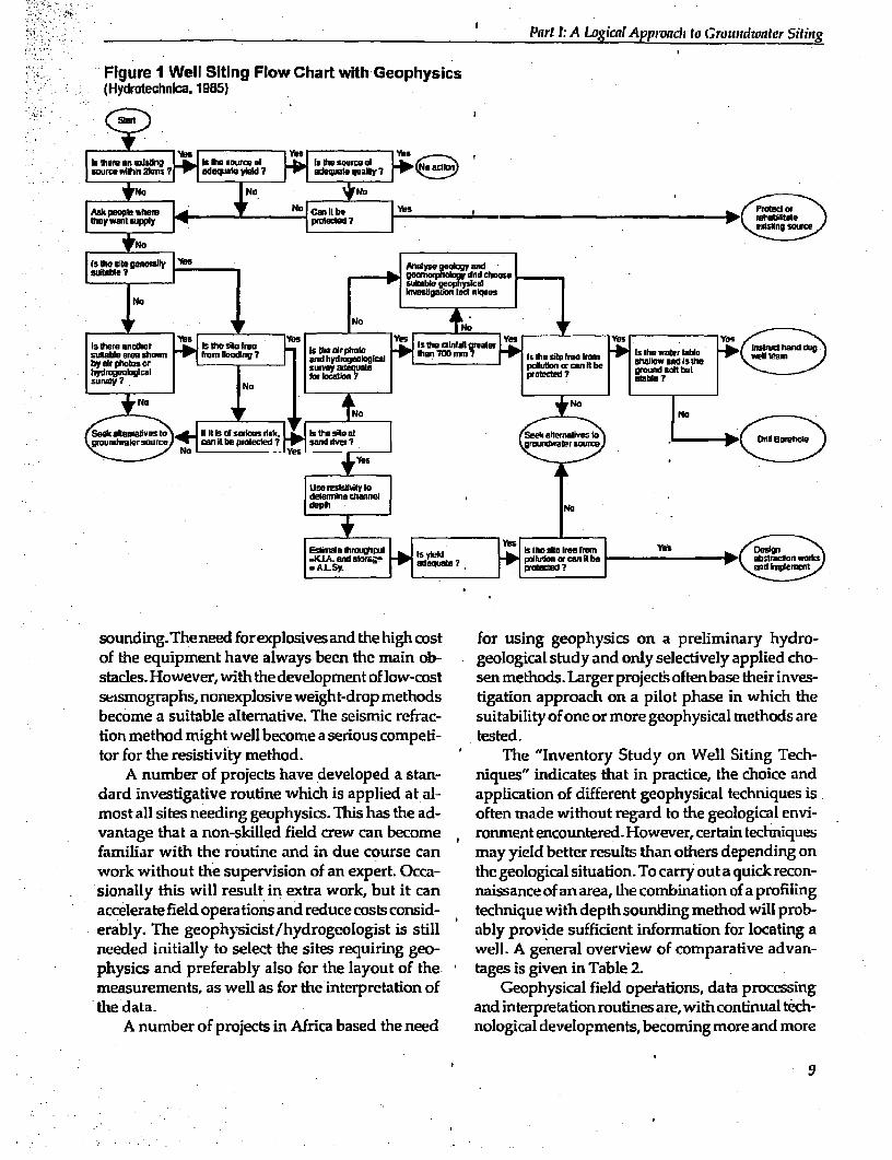
Figure 1 Well Siting Flow Chart with Geophysics(Hydratechnica. 1985)
is ft soufce O' Is on soome d~~~~~~~~~~~~~~~~inin aec
No ~ ~ ~ ~ ~~N
groundnleraurco .an Ctb rotce and itl~ gbewir craDllHrh
prolease 7 Yes mss FeeFmWSDei
ts VW site gerwallir AnW ww~~~~~~~~~~~~~~~~~~~~~~~~~ad n0mel
becombe a=utbe lentie0h simcrerc utaiiyofoeo mr ephsclmehd r
most.all sites needing g sis This has th to he, g i e
work wihot7h sueviind hdofnepr.Oc- tegeological Ih situfatioxn. ofto carr Isutaucrcnsionally his willresult inextra wok, but itcan naisance of a area,pteucombinaioncof aprofilin
accelerate fild operation and reduce ostosd tecniqecwthd det onigmehdwlrb
physics,and preferably also f
measurements, as well~~ asfrteitepeaino Gohsitcalfelopatosdtarcein
-~~~~~~~~~~~~~~~~~~el Noo
Es*rWe j hhipe Isn Mese-ie~~~~~~~~~~~~~~K%n ?_ o >| oeoia
tsoihe Ta ae iterpretan t hroe utis far,g witophih cntminaly h-
Afth nquimbert ofaroet inafrica baedn the need nbgological stdevelopments,ebecmingemor anpid mhore
AEnumber of; projectshave. developed a stan- niques" indicatesthatinpractice, the cidllBone and
familiar with the routine an~~~~~~~~~~~~~~~~d0 ninH duiel corecn myyedbte.eslsta tesdpnigo
wor wihu th sprislion lofX an exet Occak theneloia situain Im carry ou aqikrcnsionaly ths wil reslt i extr work bu it i ca naisanc of anmra Ith cobnto of a profnliongwo
erbl.Th eohyiis/ydogoogs is stl abl prv ded sufcetifomto?o lcting a
physdics ahndpefedfrably lsosieadhb for thuaotofte tgsing gieopysc in Tal 2 rlmnryhdomfteaequipments hasvel aswy been the inepeation ob- -Geophycasical fied oplelectionsy daaproesiednho
the datgaph,oepoieeih-rp d tiandionterpretachionrotearewiffiphaseinua whichth
A number of projects inv Africaloped th stan- nolog"inicalteelpesnthat beprcmice, more andoicean
dardinvstiatie ruhn whih i aplie atal- applcaton f dffeentgeopysial echiqus 9

FINDING GROUNDWATER: A PROJECT MANAGER'S GUIDE TO TECHNIQUES AND How TO USE TllEbl
simple to apply. However, there is a danger of whales and homing pigeons (Williamson, 1987).putting too much emphasis on the application of The method itself is certainly low-cost, requiring-sophisticated technology and too little on the in- only a forked stick rods or a pendulum- In many
0-d 0 sight into the underlying assumptions and prin- places dowsing has been used as the sole method.ciples on which the technical operations are based. If applied along the lines suggested by a few hydro-Skill in operating the instruments and producing geologists as a biophysical profiling method, itcomputer readouts based on mathematical and somewhatresembles the magnetometric method inphysical simplifications does not necessarily mean field practice. Perhaps on this basis dowsing couldequal hydrogeological knowledge of the area of play a scientifically-acceptable role in the well sit-interest. The geophysical practice should be seen ing process as a profiling technique. If this is theas a servant of the hydrogeological discipline. case, just as with anygeophysical method, interpre-
Given the relatively simple operation of mod- tation of the 'measurements' should be carried outem geophysical equipment, fieldwork does not within the context of the larger hydrogeologicalnecessarily require the daily supervision of a geo- investigation.physicist. Geophysical fieldworkshould,however, It is recommended that the application of geo-be preceded by a hydrogeological reconnaissance physical methods be attempted with the supervi-of the area to determine where the geophysical sion of a geophysicist or a hydrogeologist withmeasurements are tobe carried out. Further prepa- geophysical experience.rations involve the selection of the geophysical A range of commercially produced equipmentmethod,procuringanynecessary transport, design- is available and is listed in Appendix III. Clearly,ing the geophysical fieldwork, and training the field recent developments, especially the application ofteam. microelectronics, have done much to change and
Interpretation of the field data is carried out by simplify geophysical field practice, making thean experienced geophysicist or hydrogeologist. In- measurements, data processing and interpretationterpretation of resistivity and seismic refraction is faster, more reliable, and more applicable tocurrently carried out with the help of a portable groundwater investigations. When written offcomputer in the field, thus speeding up geophysi- against a substantial nunber of surveys, ground-cal investigations considerably. Depending on the water investigations are, in many hydrogeologicalaccessibility of the site for the geophysical work and enviromnents, a healthy commercial enterprise. Itthe complexity of the geology, one team can often follows that investment in advanced equipment isconduct one or more sitings per day. warranted and that facilitating importation and
Dowsingorwaterdiviningmayalsobeconsid- making credit facilities available for the purchaseered a geophysical exploration method, although of such equipment is a more viable option than aits role in groundwater exploration remains con- return to guesswork and acceptance of a high per-troversial. A recent scientific appraisal of dowsing cenitage of dry wells.suggests that it might be based on a human re- Of the 25 low-cost rural water supply projectssponse to changes in the earth's magnetic field, that provided information concerning the compo-similar to the principles of navigation applied by sition of geophysical field crews, 18 repot ied that
Table 2: Suitability of Common Geophysical Methods in Different Hydrogeological EnvironmentsResistivity
Hydrogeolegical Seismic Eketc-environment Sounding Profiling refraction magnetics VLF
Unconsolidated sediments ++ + + O +Consolidated sediments + + + a aSediments fresh/salt water ++ + a + aVolcanics + a o + °Basement depth to bedrock ++ + ++. + +Basement faultsifractures + +4 + ++ ++
++ very suitable.+ suitable.O not verj suitable.
It)
Parl t: A Logical Approncht fo Grouondwater Siting
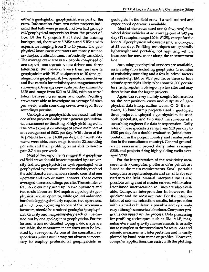
either a geologist or geophysicist was part of the geologists in the field crew if a well trained andcrew. Information from two other projects indi- experienced operator is available.cated that both were present, and two had geologi- Most of the crews used one (a few, two) four-cal/geophysical supervision from the project of- wheel drive vehicles at an average cost of $42 perfice. Of the 10 projects that listed the training day (11 samples, range $20 to $125), except for thebackground, there were 5 MSc-s and 5 BSc-s with lone VLF geophysicistwho used a small motorcycleexperience ranging from 3 to 15 years. The geo- at $3 per day. Profiling techniques are generallyphysical instrument operators are mostly trained lightweight and portable, not requiring vehicleon-the-job, while labourers are basically unskilled. transport for movement along the measurementThe average crew size is six people comprised of line.one expert, one operator, one driver and three Assuming geophysical services are available,labourers). But crews can vary from just one (a an investigation including geophysics (a numbergeophysicist with VLF equipment) to 10 (one ge- of resistivity sounding and a few hundred metersologist, one geophysicist, two operators, one driver of resistivity, EM or VLF profile, or three or fourand five casuals for resistivity and magnetometric seismic spreads) is likely to be about $1,000 per sitesurveying). Average crew costs per day amount to forsmall projects involvingonly a fewsites and may$325 and range from $20 to $1,250, with no corre- drop below that for larger projects.lation between crew sizes and costs. Profiling Again the survey mainly sought informationcrews were able to investigate on average 5.5 sites on the composition, costs and outputs of geo-per week, while sounding crews averaged three physical data interpretation teams. Of 24 the an-soundings per site. swers, 13 handpump projects used a geologist,
Geologists orgeophysicists were used in all but three projects employed a geophysicist, six usedoneoftheprojectsdealingwith general groundwa- both specialists, and two used the services of ater assessment or the siting of high yielding wells. consulting engineer for data interpretation. DailyThe crews consist on average of seven members at rates of these specialists range from $10 per day toan average cost of $622 per day. With three of the $850 per day for a double evaluation (initial inter-16 projects far over $1000 per day, their resistivity pretation in the project country and reinterpreta-teams were able, on average, to make 22 sounding tion in the consultant's country). General ground-per site, and their profiling teams able to investi- water assessment project daily rates averagedgate 2.7 sites per week. $238, and projects siting high yielding wells aver-
Most of the respondents suggest that geophysi- aged $299.cal field crews should be accompanied by a univer- For the interpretation of the resistivity mea-sity trained geophysicist or hydrogeologist with surements a computer, plotter and/or printer aregeophysical experience. For the resistivity method listed as the main requirements. Small portablethe additional crew members should consist of one computers are quite adequate and can often be car-operator and two or more laborers. These crews ried into the field. Manual interpretation is alsoaveraged three soundings per site. The seismic re- possible using a set of master curves, while calcu-fraction crew may need up to two operators and lItor-based interpretation routines are also avail-two to six labourers. EM requires a geologist/geo- able. Computer interpretation is, however, thephysicist and an operator, while ground radar and quickest and the most accurate. For the interpre-borehole logging similarly requires two operators, tation of seismic refraction results, interpretationof which one, according to one of the two manu- with a small calculator is possible and relativelyfacturers, should be c trained geologist/geophysi- easy although somewhat laborious. Computer pro-cist. Gravity and magnetometery each can be car- grams can speed up the process. Data processingried out by one geologist or geophysicist. For the for profiling techniques such as EM, VLF, mag-former, when no detailed topograrhic maps are netometery and gravity measurements is usuallyavailable, the measurement statioins must be lev- not as complex as the procedures for resistivity andelled by surveyors. As one of the consultant re- seismic measurement interpretation and is easilyspondents points out, it may not always be neces- plotted by hand onto maps or profiles. However,sary to employ professional geophysicists or computer applications can assist with the plotting.
11
FINDING GROUNDWATEm: A PROJECT MANAGER'S GuiDiE TO TECHNIQUES AND How TO USE THEM
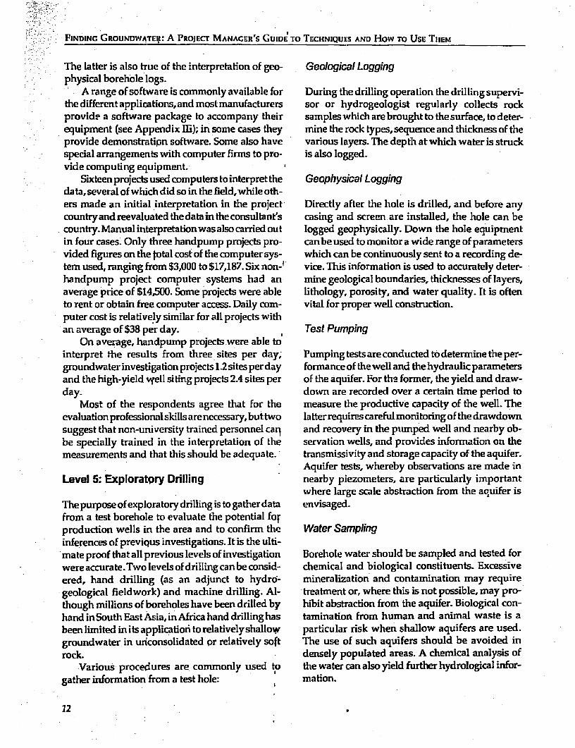
The latter is also true of the interpretation of geo- Geological Loggingphysical borehole logs.
A range of software is commonly available for During the drilling operation the drilling supervi-the differentapplications,and mostmanufacturers sor or hydrogeologist regularly collects rockprovide a software package to accompany their samples which are brought to the surface, to deter-equipment (see Appendix 1I;); in some cases they mine the rock types, sequence and thickness of theprovide demonstratipn software. Some also have various layers. The deptl at which water is struckspecial arrangements with computer firms to pro- is also logged.vide computing equipment. 4
Sixteen projects used computers to interpret the Geophysical Loggingdata,several of which did so in the field,while oth-ers made an initial interpretation in the project Directly after the hole is drilled, and before anycountryandreevaluatedthedataintheconsultant's casing and screen are installed, the hole can becountry.Manualinterpretationwasalsocarriedout logged geophysically. Down the hole equipmentin four cases. Only three handpump projects pro- canbeused to monitor a wide range of parametersvided figures on the total cost of the computer sys- which can be continuously sent to a recording de-tem used, ranging from $3,000 to $17,187. Six non-1 vice. This information is used to accurately deter-handpump project computer systems had an mine geological boundaries, thicknesses of layers,average price of $14,500. Some projects were able lithology, porosity, and water quality. It is oftento rent or obtain free computer access. Daily com- vital for proper well construction.puter cost is relatively similar for all projects withan average of $38 per day. Test Pumping
On average, handpump projects were able tointerpret the results from three sites per day; Pumping tests are conducted to determine the per-groundwater investigation projects 1.2sites perday formance of thewell and the hydraulic parametersand the high-yield wyell siting projects 2A sites per of the aquifer. For the former, the yield and draw-day- down are recorded over a certain time period to
Most of the respondents agree that for the measure the productive capacity of the well. Theevaluation professionalskills arenecessary,but two la tterrequires careful monitoring of the drawdownsuggest that non-university trained personnel can and recovery in the pumped well and nearby ob-be specially trained in the interpretation of the servation wells, and provides information on themeasurements and that this should be adequate. transmissivity and storage capacity of the aquifer.
Aquifer tests, whereby observations are made inLevel 5: Exploratpry Drilling nearby piezometers, are particularly important
where large scale abstraction from the aquifer isThe purpose of exploratory drilling is to gather data envisaged.from a test borehole to evaluate the potential forproduction wells in the area and to confirm the Water Samplinginferences of previqus investigations. It is the ulti-mate proof that all previous levels of investigation Borehole water should be sampled and tested forwere accurate.Two levels of drilling can be consid- chemical and biological constituents. Excessiveered, hand drilling (as an adjunct to hydrd- mineralization and contamination may requiregeological fieldwork) and machine drilling. Al- treatment or, where this is not possible, may pro-though millions of boreholes have been drilled by hibit abstraction from the aquifer. Biological con-hand inSouth East Asia, in Africa hand drillinghas tamination from human and animal waste is abeen limited in its application to relativelyshallow particular risk when shallow aquifers are used.groundwater in uriconsolidated or relatively soft The use of such aquifers should be avoided inrock. densely populated areas. A chemical analysis of
Various procedures are commonly used to thewater can also yield further hydrological infor-gather information from a test hole: mation.
12

Part I.:A Logical Approach to Groundwater Siting
It is recommended that production wells be have a variety of rigs from large rotary equipmentgeologically and geophysicallylogged, and pump- to light portable survey rigs; their fees will varying and water quality tests be conducted. This op- accordingly.timizes well construction and provides data for Theuseoflightandheavyhanddrillingequip-planned wells. ment has been very successful in unconsolidated
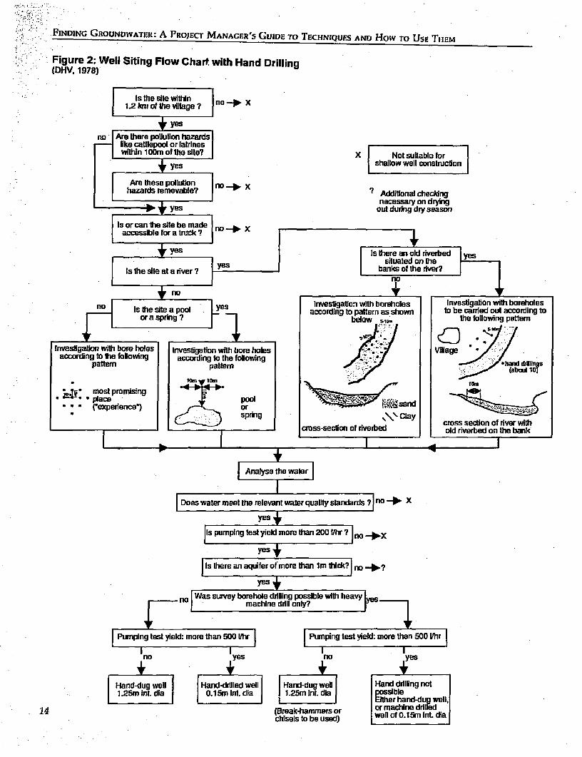
In relatively soft rock, the information can be rock. Two projects reported using hand drilling asacquired by exploratory hand drilling, and geo- part of their siting procedure. In suitable geologi-physical investigations are usually unnecessary. calconditions, hand drilling offers a quick andsureSeveralhand drilled holescanbeeasilyand cheaply siting technique which does not rely upon expertmade to determine the best site for a production assistance and, in certafl, cases, can be used to drillwell, which will be dug or drilled by hand as well. the final production wells'Whether or not hand drilling is possible depends Level 5 of the investigation, (machine) testdrill-on local geological conditions and will be deter- ing, is very expensive due to the high operatingmined in the hydrogeological investigation phase. costs of a modern drilling rig. Depending on theBased on the pumping test, the calculation of aqui- type ofdrilling, (hand drillingnot induded) the costfer permeability and storage capacty will deter- may be estimated at $50 - $200 per meter (low inminewhethera hand-dugorhand-drilled wellwill Southern Africa, high in West Africa), excludingbe more suitable (hand-dug for greater well stor- casing, screens, developing, testing, and hand-ageinlow-permeabilityaquifers).A wellsitingflow pump. Only the largest projects in which the costchart with testhand drilling used in a CWS project of drilling exploratory holes can be written offin Tanzania is shown in Figure 2. against a large number of production holes will it
If the fifth and final level of investigation, ex- befinancially attractive to engage in such test drill-ploratory drilling, is called for, a considerable fi- ing. When more than one well is needed in a cer-nancial outlay may be required on behalf of the tain area, the first few can be considered test holes,project Hopefully this will be justified by an in- to be sited and used to provide information aboutcrease in success rates and a lower mean drilling the aquifer and to calibrate geophysical sounding,depth. In cases where the project intends to drill before a decision is made concerning the locationboreholes, it is assumed that there is access to a of the remaining holes. When water is struck indrilling rig, which will be used for the exploratory adequate quantities such test holes can subse-holes. Otherwise it will almost certainly be neces- quently be turned into production weUs.sary to contract this work out. Contractors may
13
FINDING GROUNDWATER: A PROJECT MANAGER'S GUIDE TO TECHNIQUFS AND HOW TO UsE THEM
Figure 2: Well Siting Flow Chart. with Hand Drilling(DHV, 1978)
:. i - Is the site within no X12 kn of he village ?
- r~~~~ yes
no Are there polluilon hazardslike cattlepool or latrineswvtiin 1 0Dm of the site? X Not suktable for
l yes shallow well construclTon
Are these polluton o _ Xhazards removable? 7 Additional checking
necessary on drying+ yes out during dry season
Is or can the site be made no X-- t ~~~~~acessibe for a truck v|q
l i yes Is there an old riverbedsituated on the
Is the site at a river ? yes banks of the river?I ~~~~~~~~~~~~~~~nol no +
nio i s the seseapool investigatc-i with boreholes invesfgabon with boreholesIs the site a pool Y according to pattem as shown to be carried out according toor a spring ? _ below t he foliowing pattem
invesiao with boe holes Investigation with bore holes accorIngt the boloweng according to the folowing h dr--h
pattern pattem .7 (abaut
:~~~~~~~~~~~~~~o -o ta\tm. ;_. . amost pmmistng
.. place Pool sand
.. ('experience') or. c J spring .clu aay cross section of nver with
cress-section of &erbed old riverbed on the bank
|Arnalyse the water]|
Does water meet the relevant waler quality standards ? no _ X
yes +
Is pumping test yield more than 200 ih1r 7 no _X
yes
Is there an aquifer of more than Im thick? no _?
yes4
Was sUrvey borehole drilling possible with heavyg no E t machine drill only? ye
Pumping test yield: more than 500 ilhr Pumping test yield: more than 500 Ihr
no yes no yes
|FHand-dug well Hand-drilled well ad-g well Hand driling notI 1.25m inL dia I 0.1 5m int. dia 1 125m InL diaI possible
(Oa I Either hand-dug well,14 cakhiseisbbe ored) | or machine drilled
chiseis to be used) welo .mmtdi
Success and Cost
M ost water supply prujects operate within and the well average costs from Table 3 shows thatM fixed financiall constraints. Thus, the costs of for low cost rural supplies an average reduction ingroundwater investigations are a determinant in siting cost of 14 percent was reported. But for thewhich methods are applied. ground water investigation and high yield siting
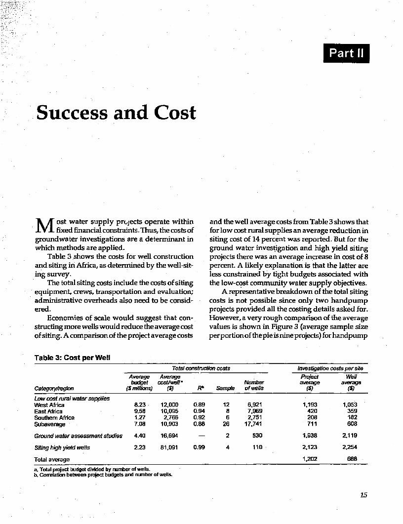
Table 3 shows the costs for well construction projects there was an average increase in cost of 8and siting in Africa, as determined by the well-sit- percent. A likely explanation is that the latter aremg survey, less constrained by tight budgets associated with
The total siting costs include the costs of siting the low-cost community water supply objectives.equipment, crews, transportation and evaluation; A representative breakdown of the total sitingadministrative overheads also need to be consid- costs is not possible since only two handpumpered. projects provided all the costing details asked for.
Economies of scale would suggest that con- However, a very rough comparison of the averagestructing more wells would reduce the avenage cost values is shown in Figure 3 (average sample sizeof siting. A comparison of the project average costs per portion of the pie is nine projects) for handpump
Table 3: Cost per WellTotal construction costs Investigation costs per site
Average Average PRct wellbudget costlwehla Number average average
categoiy/re glen (S millions) ($) Rb Sample of wells (5)()
Low cast rural water suppliesWest Africa 8.23 12,000 0.89 12 6,921 1,193 1,053East Africa 9.58 10,025 0.94 8 7,969 420 359Southern Africa 1.27 2,766 0.92 6 2,751 208 182Subaverage 7.08 10,903 0.88 26 17,741 711 608
Gmound water assessmnent studies 4.40 16,694 - 2 530 1,938 2,119
Siting high yield wells 2.23 81,091 0.99 4 110 2,123 2,254
Total average 1,202 688
a. Total project budget divided by number of wells.b. Correlation between project buidgets and number of wells.
,' -'0='''. 'X ~ ~ ~ ~ ~ ~ ~ ~ ~ ~ ~ ~ ~ ~ ~ ~ ~ ~ ~~2
XI
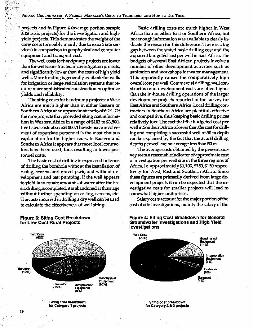
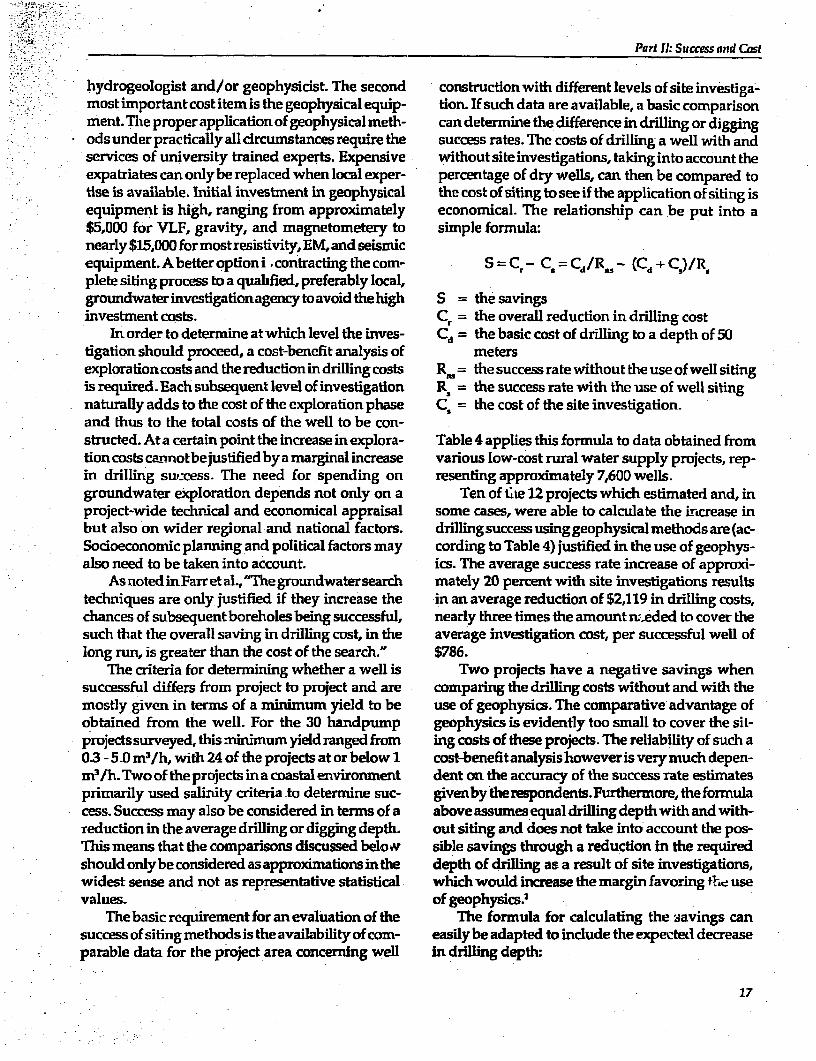
FINDING GROUNDWATER: A PROJECT MANAGER'S GUIDE TO TECHNIQUES AND How TO USE THEM
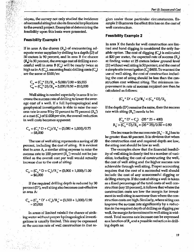
projects and in Figure 4 (average portion sample Basic drilling costs are much higher in Westsize is six projects) for the investigation and high- Africa than in either East or Southern Africa, butyield projects. This demonstrates the weight of the not enough information was available to clearly in-crew costs (probably mainly due to expatriate ser- dicate the reason for this difference. There is a bigvices) in comparison to geophysical and computer gap between the stated basic drilling cost and theequipment and transport cost. apparentbudgetedcostper wellin East Africa. The
Thewellcosts forhandpump projects arelower budgets of several East African projects involve athanfor wells constructed in investigationprGjects, number of othler development activities such asand significantly low er than the costs of high yield sanitation and workshops for water management.wells. More funding is generally available for wells This apparently causes the comparatively highfor irrigation or large reticulation systems that re- overall cost per well. Commercial drilling, well con-quire more sophisticated construction to optimize struction and development costs are often higheryields and reliability. than the in-house drilling operations of the larger
Thesiting costs for handpump projects inWest development projects reported in the survey forAfrica are much higher than in either Eastern or EastAfrica and SouthemrAfrica. Local drillingcon-Southern Africa at an approximate ratio of 6:21. Of tractors in Southern Africa are plentiful, effectivethe nine projects thatprovided siting cost informa- and competitive, thus keeping basic drilling pricestion in Western Africa in a range of $103 to $3,500, relatively low. The fact that the budgeted cost perfivelisted costs above $1000.The extensive involve- wellinSouthernAfricaislower thanthecostfordrill-merit of expatriate personnel is the most obvious ing and completing a successful well of 50 m depthexplanation for the higher costs. In Eastem and can be explained by the fact that the actual drillingSouthern Africa it appears that more local contrac- depths per well are on average less than 50 m.tors have been used, thus resulting in lower per- The average costs obtained by the present sur-sonnel costs. vey seem a reasonable indicator of approximate cost
The basic cost of drilling is expressed in terms of investigation per well site in the three regions ofof drilling the borehole without the installation of Africa, i.e. approximately $1,100, $350, $150 respec-casing, screens and gravel pack, and without de- tivelv for West, East and Southern Africa. Sincevelopment and test pumping. If the well appears these figures are primarily derived from large de-to yield inadequate amounts of water after the ba- velopment projects it can be expected that the in-sicdrillingiscompleted, itis abandoned atthis stage vestigative costs for smaller projects will lead towithout further spending on casing, screens, etc. somewhat higher unit prices.The costs incurred in drillinga drywel can be used Salary costs account for the major portion of theto calculate the effectiveness of well siting. cost of site investigations, mainly the salary of the
Figure 3: Siting Cost Breakdown Ficgure 4: Siting Cost Breakdown for Generalfor Low-Cost Rural Projects Groundwater Investigations and High Yield
investigations
Field Crew Field Crew(52SS _= p% Geophysical
Equipment
-_'~->~> InterpretationEquipment__ _s ~~~~~~~~~~~~~~~~~~~~~~~~~(1l%)prln
Tratsort___ (Evaluator
GenphyTransport-Eupet(14%)
Evaluator Interpretation (20)(1 5%) Equipment
(3%)
Siting cost breakdown SKtlng cost breakdownfor Category 1 projects for Category 2 & 3 projects
16
Part 11.: Success and Cost
bydrogeologist and/or geophysicist. The second construction with different levels of site investiga-most important cost item is the geophysical equip- tion. If such data are available, a basic comparisonment. The proper application of geophysical meth- can determine the difference in drilling or diggingods under practically all drcumstances require the success rates. The costs of drilling a well with andservices of university trained experts. Expensive without site investigations, taking into account theexpatriates can only be replaced when local exper- percentage of dry wells, can then be compared totise is available. Initial investment in geophysical the cost of siting to see if the application of siting isequipment is high, ranging from approxilmately economical. The relationship can be put into a$5,000 for VLF, gravity, and magnetometery to simple fonnula:nearly$15,000 for mostresistivity, EM, and seismicequipment.Abetteroptioni .contractingthecom- S = C.- C. = Cd/R. - (Cd + C)/R,plete siting process to a quahfied, preferably local,groundwater investigationagency to avoid the high S = the savingsinvestment costs. Cr = the overaU reduction in drilling cost
In order to determine at which level the inves- Cd = the basic cost of drilling to a depth of 50tigation should proceed, a cost-benefit analysis of metersexploration costs and the reduction in drilling costs R. = the success rate without the use of well sitingis required. Each subsequent level of investigation R, = the success rate with the use of well sitingnaturally adds to the cost of the exploration phase C. = the cost of the site investigation-and thus to the total costs of the well to be con-structed. At a certain point the increase in explora- Table 4 applies this formula to data obtained fromlion costs carnnotbejustified by a marginal increase various low-cost rural water supply projects, rep-in drilling success. The need for spending on resenting approximately 7,60D wells.groundwater exploration depends not only on a Ten of Cte 12 projects which estimated and, inproject-wide tecihical and economical appraisal some cases, were able to calculate the Lrtcrease inbut also on wider regional and national factors. drillingsuccess using geophysical methods are (ac-Socioeconomic planning and political factors may cording to Table 4) justified in the use of geophys-also need to be taken into account. ics. The average success rate increase of approxi-
AsnotedinFarretal.,"Thegroundwatersearch mately 20 percent with site investigations resultstechniques are only justified if they increase the in an average reduction of $2,119 in drilling costs,chances of subsequent boreholes being successful, nearly three times the amount uteded to cover thesuch that the overall saving in drilling cost, in the average investigation cost, per successful well oflong run, is greater than the cost of the search." $786.
The criteria for determining whether a well is Two projects have a negative savings whensuccessful differs from project to project and are comparing the drilling costs without and with themostly given in terms of a minimum yield to be use of geophysics. The comparative advantage ofobtained from the well. For the 30 handpump geophysics is evidenfly too small to cover the sit-projects surveyed, this minimum yield ranged from ing costs of these projects. The reliability of such a03 - 5.0 m3 /h, with 24 of the projects at or below 1 cost-benefit analysis however is very much depen-m3 /h. Two of the projects ina coastal environment dent on the accuracy of the success rate estimatesprimarily used salinity criteria to determine suc- givenbytherespondents.Furfiermore,theformulacess. Success may also be considered in terms of a above assumes equal drilling depth with and with-reduction in the average drilling or digging depth. out siting and does not take into account the pos-This means that the comparisons discussed belo-v sible savings through a reduction in the requiredshouldonlybeconsideredasapproximationsinthe depth of drilling as a result of site investigations,widest sense and not as representative statistical which would increase the margin favoring the usevalues, of geophysics)
The basic requirement for an evaluation of the The formula for calculating the savings cansuccess of siting methods is the availability of com- easily be adapted to include the expected decreaseparable data for the project area concerning well in drilling depth:
17
F1iNDING ;ROUNOJATER: A PROJECT MANAGER'S GUIDE TO TECHNIQUES AND HOW TO USE THEM
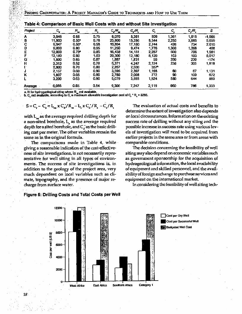
Table 4: Comparlson of Basic Well Costs with and without Site InvestigationPiaject Cd R.. R. CIR.. CdIR, C, C. C,1Rs S
A 3,946 0.65 0.75 6,070 5,261 809 1,361 1.815 -1,006B 11,900 0.50' 0.78 23,800 15,256 8,544 2,250 2.885 5,659C 9,947 0.50' 0.58 19,894 17,150 2,744 426 734 2,010D 9,000 0.80 0.95 11,250 9,474 1,776 1,300 1,368 408E 12,000 0.73' 0.85 16,438 14,151 2,287 600 706 1,581F 12,180 0.60 1.00 20,300 12,180 8,120 103 103 8,017G 1,600 0.85 0.87 1,887 1.831 56 200 230 -174H 3.313 0.52 0.78 6.371 4,247 2,124 238 305 1,819I 2,000 0.70 0.80 2,857 2,500 357bJ 2,157 0.60 0.90 3,595 2,397 1,195 60 67 1,131
- K 1,807 0.65 0.90 2,780 2,008 772 90 100 672L 3,200 0.63 0.90 5,079 3,555 1,524 580 644 880
Average 6,088 0.65 0.84 9,366 7,247 2,119 660 786 1.333
a. R for hydrmgeological siting where R,. not available.b. C. not available, according to C, a madimum allowable investigation cost of C,'* R. = 5285.
S=C - C =L xCd/R 5 -Ls xCd/R5 -C./R,K The evaluation of actual costs and benefits todetermine the extent of investigation also depends
with L, as the average required drilling depth for on local circumstances. Information on the existinga non-sited borehole, L, as the average required success rate of drilling without any siting and thedepth for a sited borehole, and C; as the basic drill- possible increase in success rate using various lev-ing cost per meter. The other variables remain the els of investigation will need to be acquired fromsame as in the original formula. earlier projects in the same area or from areas with
The comparisons made in Table 4, while comparable conditions.giving a reasonable indication of the cost-effective- The decision concerning the feasibility of wellness of site investigations, is not necessarily repre- siting mayalso depend on economic variables suchsentative for well sifing in all types of environ- as government sponsorship for the acquisition ofments. The success of site investigations is, in hydrogeological infornation, the local availabilityaddition to the geology of the project area, very of equipment and skilled personnel, and the avail-much dependent on local variables such as cli- abilityofforeignexchangetopurchaseservicesandmate, topography, and the presence of major re- equipment on the international market.charge from surface water. In considering the feasibility of well siting tech-
Figure 5: Drilling Costs and Total Costs per Well
12000-
¶ . - .]w a Cost per Dry Well10000 -. Cost per Successful weD
i * Budgeted Well CostZi 8000 £4U,
~~~~~~4 :
Zi
8 4000-
2OW -U -
0West Africa East Africa SouLthemn Africa category 1
Part I.: Success and Cost
niques, the survey not only studied the incidence gion under those particular circumstances. Ex-of successful siting but also its financial implications ample 2 illustrates the effect this has on the cost ofto the overall project. Examples of determining the well construction.feasibility upon this basis were presented.
Feasibility Example 2Feasibility Example I
In area X the funds for well construction are lim-If in area A the chance (RA) of encountering ad- ited and hand digging is considered the only fea-equate water supplies by drilling to a depth (D) of sible option. The cost of digging (Cd) is estimated50 meters is 90 percent, and in area B the chance at $20 per meter, the expected rate of success (Rx)(K.) is 50 percent, the average cost of drilling a suc- at finding water at 25 meters below ground levelcessful well in area B (C.) will be nearly twice as (D) withoutwell siting isSO percent, and the costofhigh as in A (CA), assuming basic drilling costs (Cd) a simple site investigation (C) $400. To warrant theare the same at $100/m: use of well siting, the cost of construction indud-
ing the cost of siting should be less than the con-CA = (C-d D)/RA = 5,000/0.90 = $5,555 struction cost without siting. The minimum im-CB = (Cd* D)/R 5 = 5,000/0.50 = $10,000 provement in rate of success required can then be
calculated as follows:Well siting is needed especially in area B to in-
crease the success rate of drilling to lower the aver- (Cd * D' + C)/R < (Cd * D)/Rxage cost of a well. If a full hydrogeological andgeophysical investigation is able to raise the suc- If the depth (DI remains the same, then the successcess rate in area B by 25 percent to 75 percent (R.') rate with siting (R,11 needs to be:at a cost (C) of $1000 per site, the overall reductionin well costs becomes apparent: (Cd * D' + C) (20 * 25 + 400)
CR; > (Cd * D)/RI = (20 * 25)/0.50 0.90Cr,1 = (Cd, D + Cr.)/R,,= (5,000 + 1,000)/0.75
= $8,000 The increase in the success rate (Rx'- K) has tobe greater than 40 percent. It is obvious that when
The use of well siting represents a saving of 20 the construction cost and required depth are low,percent, including the cost of siting. It is evident the siting cost should be low as well.that in area A, a similar siting expense to raise the The examples show that the financial feasibil-success rate to 100 percent (RA') would not be jus- ity of well siting is closely tied to a number of vari-tified as the overall cost per well would actually ables, induding the cost of constructing the well,increase due to the cost of siting: the cost of well siting and the higher success rate
achievable through well siting. Proper accountingCA = (Cd * D + C )/R; = (5,000 + 1,000)/1.00 requires that the cost of a successful well should
$6,000 include the cost of any unsuccessful digging ordrilling attempts. If the cost of siting a well is taken
If the required drilling depth is reduced by 30 as a fixed percentage of the total costs of well con-percent (D'), well siting also becomes cost-effective struction (say 10 percent), it follows that where thein area A: construcdon costs are low the margin for invest-
ment in well siting is narrower than where the con-CA = (C,, * D' + C)/R; = (3,500 + 1,000)/0.90 structioncosts arehigh.Similarly,wheresiting can
= $5,000 improve the success rate signiificantly by a reduc-tion in the required depth of drilling or digging per
In areas of limited rainfall the chance of strik- well,themarginforinvestmentinwellsitingiswid-ing water without proper hydrogeological investi- ened. Total success rate increase can be expressedgations is usually limited. This may be expressed as a functionof Rxand a possible reductionin drill-as the success rate of well conistruction in that re- ing depth as:
19
FINDING GROUNDWATER: A PRoJEcT MANAGER'S GUIDE TO TECHNIQUES AND How To USE THEM
D/R - D'/R' decrease, expenditure on well siting will need to
dR = D/R * 100 (%) bejustifiedbyhigherincreases in therate of success.
The cost of well siting is also an important vari- Noteable, When the siting costs are high, the compara-i -tive advantage of siting is reduced. If they are low, 1. The formula for calculating the savings can easily bethe advantage is gr,aer. .adapted to include the expected decrease in drilling depth:
- the advantage is greater.If the well construction program is a local com- S = - C, = x - x -
munity initiative without external funding, the where L is the average required drilling depth for afunds are likely to be very limited and te hand borehole, and Cd* is the basic drilling cost per meter. Thedrilling or digging option will often be the only other variables remain as in the original formula.alternative. Consequently, as construction costs
20
Part III
Case Study
The Lake Basin Development Authority (LBDA) fault systems can be identified as dark lineationsThas initiated a community water supply due to increased soil moisture and vegetation den-
program in Nyanza Province in Western Kenya sit-y. In roughly half the area (some 6,000 kn2) overwith the aim of improving the generally poor wa- 3,000 fault structures have been identified. It haster supply through the d6&elopment of hand- proven essential that such features be accuratelypumped water supplies. In 75 percent of the prov- located in the field, as a location error of 10 metersince, few permanent'surface water resources are can result in a dry hole. The standard field surveyfound. Wh-enever the groundwater table can be per site consists of two electromagnetic profiles offound at less than 20 meters below ground level, about 400 to 600 meters length, one resistivity pro-hand-dug wells are considered. In the western part file (Wenner array) and three to five resistivity.of the province where the water table is deeper, soundings (Schlumberger array) evenly spread andmachine drilled boreholes have to be constructed. generally perpendicular to the electromagneticThe province is mainly underlain by volcanic rocks profiles ~:, shown in Figure 6.of Precambrian and Tertiary age, with some Pleis- The equipment consists of an ABEM SAS 3005tocene sediments present. The area has been sub- Terramneter and a Geonics EM 34-3. The latter provedject to extensive tectonic activity since late Tertiary especially sensitive to narrow anomalies caused bytimes. Based on the assumption that the most pro- fault and fracture zones. The resistivity data areductive aquifers in hard rock usually occur in faults interpreted on a microcomputer with a special curve-and fracture zones, a standard survey method was fitting software package, and evaluated together withdeveloped for the programby DHV Consulting En- the plotted profiling data in terms of:gineers of the Netherlands to accurately locate pro- * The presence and depth of different zones ofspectiveborehole sites in the field. This is comprised weathering.of two components: - The depth to the unweatheied bedrock.
* Mapping of faults and fracture zones by - The thidckness of aquifers.means of remote sensing. - The presence,accurate location and angle of
* Geophysical surveys carried out along pro- near vertical discontinuities such as faults, intru-ifiles across the most promising of the interpreted sive dykes and lithological boundaries.faults and fracture zones. a The salinity of the groundwater.
Regional structures and major faults show up Based on this evaluation the most suitable wellclearly on satellite images. On aerial photographs lomationandwelltype(handdugordrilled)isselected.
21
FINDINC GROUNDWATER: A PROIECT MANAGER'S GUIDE TO TECHNIQUES AND HOW TO UsE THOM
Figure 6: Schematic Layout of Geophysical Survey at Omboga Secondary School1. I}
Site morphology - - VES-S To =leak
,,:-_: _v vV v ~v-2
ToOfomb4 I V I
I A L I
. C s t t 0w0 r
----- EM and GE ProFiles ,.---lVES-13
; fN l interpreted lault zone
Recommnded breholelocatin ' >0 m OMBOAkSCoOdL
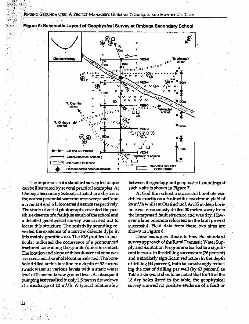
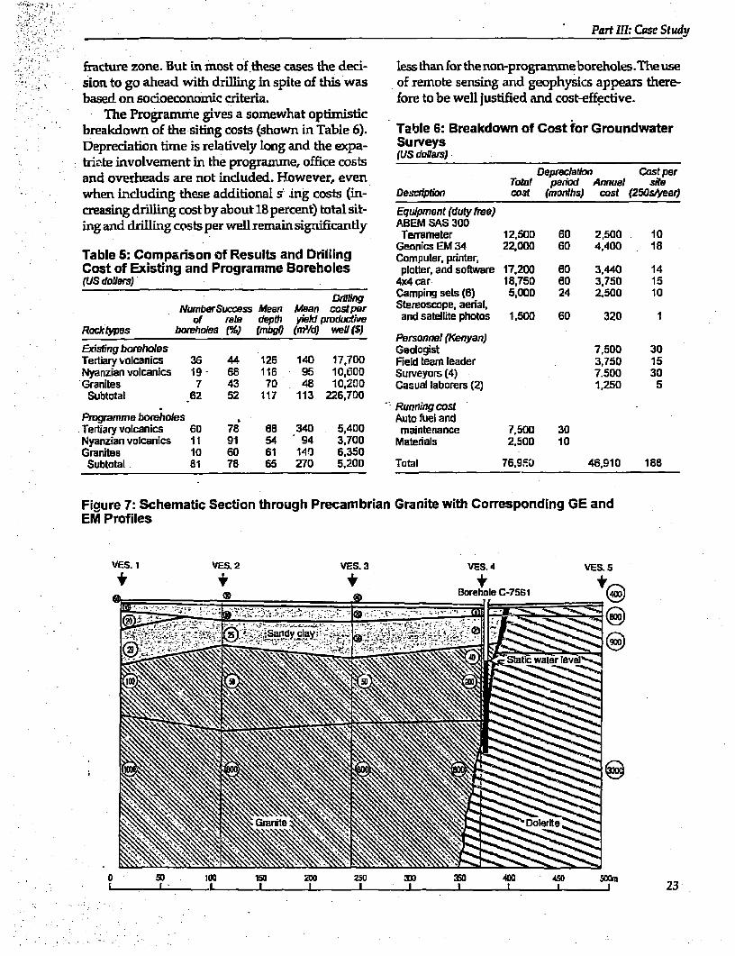
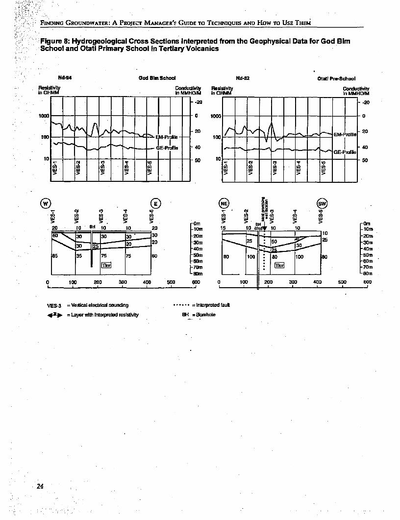
The importance of a standard survey technique between the geology and geophysical soundings atcan be illustrated by several practical examples. At such a site is shown in Figure 7.Omboga Secondary School, situated in a dry area, At God Bim school a successful borehole wasthe nearest perennial water sources were a well and drilled exactly on a fault with a maximum yield ofa river at 4 and 6 kilometres distance respectively. 24m3 /h whilst atOtati school. An 85 m deep bore-The study of aerial photographs revealed thie pos- hole was erroneously drilled 30 meters away fromsible existence ofafaultjustsouthof the school and the interpreted fault structure and was dry. H-ow-a detailed geophysical survey was carried out to ever a later borehole relocated on the fault provedlocate this structure. The resistivity sounding re- successful. Field data from these two sites arevealed the existence of a narrow dolerite dyke in shown in Figure 8.thiis mainy granitkc area. The EM profiles in par- These examples illustrate how the standardticular indicated the occurrence of a pronounced survey approach of the Rural Domestic Water Sup-~fractured zone along the granuite/dolerite contact. ply and Sanitation Programmue has led to a signifi-The location and slope of this sub-vertical zone was cant inarease in the drillin g success rate (26 percent)assessed and aborehole location selected. Te bore- and a similarly significant reduction in the depthhole drilled at this location to a depth of 52 meters of drilling (44percent),bothfactorsstronglyreduc-struck water at various levels with a static water ing the cost of drilling per-well (y 63 percent) aslevel of 24 meters below ground level. A subsequent Table 5 shows. It should be noted that for 14 of thepumpingtestresultedinonly25Smetersdrawdown 18 dry holes listed in the table, the geophysicalat a discharge of 12 m3 /h. A typical relationship survey showed no positive evidence of a fault or
22
. ~ ~ ~ ~ ~ ~ ~ ~ ~ - io
.. ~~~~~~~~~~~~ v
.- ~~~~~~~~~~~~~~~~~~1 0 . ` : :
:~~~~~~~~~~E n GE Prf C: :-ile
Part III: Case Study
fracture zone. But in most of these cases the deci- lessthanforthenon-programmeboreholes.Theusesion to go ahead with drillng in spite of thds was of remote sensing and geophysics appears there-based on socioeconomic criteria. fore to be well justified and cost-effective.
:The Programme gives a somewhat optimisticbreakdown of the siting costs (shown in Table 6). Table 6: Breakdown of Cost for GroundwaterDepreciation time is relatively long and the expa- Surveystriate involvement in the programme, office costs (US ars)
Depredatlion Cosl perand overheads are not induded. U.owever, even Tatar penad Annual sitewhen including these additional s ing costs (in- Descnrption cost (months) cost (250s/year)creasing drilling costby about 18 percent) total sit- Equipment (duty fee)ing and drilling costs per well remain significantly ABEM SAS 300
Terrameter 12.500 60 2,500 10Geonics EM 34 22.000 60 4,400 1 8
Table 5: Comparison of Results and Drilling Computer. printer,Cost of Existing and Programme Boreholes plotter, and software 17.200 60 3,440 14(US dollars) 4x4 car 18,750 60 3,750 15
Camping sets (6) 5,000 24 2,500 10NunberSuccess Mean Mean costpor Stereoscope, aenaL
of rat depth yield prductive and satellite photos 1,500 60 320 1Rocklypoes boreholes (%) (mbgl (mi'ld w PLrsonneI (Kenyan)
Existing boreholes Geologist 7.500 30Tertiary wolcanics 36 44 126 140 17,700 Field team leader 3,750 15Nyanzian volcanics 19 - 66 116 95 10,600 Surveyors (4) 7.500 30'Granites 7 43 70 48 10.200 Casual laborers (2) 1,250 5
Subtotal 62 52 117 113 226,700'~Running cost
Pmgramme boehoies . Auto fuel andTertiary volcanics 60 78 68 340 5,400 maintenance 7,500 30Nyanzian volcanics 1l 91 54 94 3.700 Materals 2,500 10Granites 10 60 61 140 6,350Subtotal 81 78 65 270 5,200 Tatal 76.9!U 46.910 188
Figure 7: Schematic Section through Precambrian Granite with Corresponding GE andEM Profiles
VES.i VES.2 VES.3 VES.4 VES. 5
Borehole C-7561
tEs~~~~~~~~~~~~~~~~~~~E
0 50. 100 150 2m0 250 300 350 400 450 50Cma a ~~~~~~~~~~~~~~~~~~23
FINDING GROUNDWATER: A PROJECT MANAGER'S GUIDE TO TECHNIQUES AND HIOW TO UsE THEM
Figure 8: Hydrogeological Cross Sections Interpreted from the Geophysical Data for God BimSchool and Otati Primary School In Tertiary Volcanics
Nd44 God Olm School Nd-52 Otati Pre-School
RPisilviy ConducdMly RslsIsiviy ConductMtyIn OHMM In MMHO=M In OHMM in MMHDIM
-20 -20
10t0 a i, c-- -10 -tO -- 1 0
2020 EM5 rile -20
: G 85 35 75 75 80 -50m 30e WI | ao IW w _00~~--,~GE-Profile G-rfl
_0 so Ei -70 .? . si-Or
0) 02 0 02 U) 0 02 UI C) (a)
uIW LU LU LU 50 6l 0 1 LU 4> > :~>* > >> > Ur O~ m
20 t0 BH 10 10 20 Fiom is5 lOdcyvI 10 10 jiiom20 20 -3~~0M 2 ~ 5-0
-40m -40m85 35 75 7-9 so ~~SOm 130 ioo so8 icto so [5Cm_ _ _ _ _ _ _ _ _ _ _ _ _ _ _ _ _ _ _ _ _ _ _ _ _ _ _ _ _ 6 001
.. __ __ _ ,_ _ ,_ _ ,_ ,_ _____... , C...m 0 100 200 300 400 500 G00 0 100 200 300 400 500 600
VES-3 =Vertical electdcal sounding ...... = Interpreted lauU
4qX.o ==Layerwithi Enterpreled resistivity BH = Borehole
24
Appendix I
WVell Siting Techniques
1. Electrical Re-sistivity Sounding Theradiating energytravelsbyseveralpaths throughthe subsurface mediumn. It is refracted along bound-
The principle of the electrical resistivity method, or aries and returns to the surface, where it can be re-vertical electrical sounding (VES),is the measurement corded by an array of detectbrs or geophones. Theof the earth's electrical resistance by passing low fre- time lapse between the shotand the first arrival of the-quency current into the ground through two metal refracted wave is plotted onto a curve. This provid es"current electrodes" and measuring the potential finformation on depths to the refracting boundary anddifference resulting across two "potentia elecftrodes." the seismic velocity of the underground layer.If the distance between the four electrodes is known Seismic refraction is suitable for low-costthen a resistivity of the earth may be calculated. In- groundwater investigation projects of a medium orcreasing the distance between electrodes effectively, large scale, since the method is rapid and providesincreases the depth of penetration of the sounding. a comprehensive amount of information at a tea-
.Electricity canbe conducted tr-ough rockcsin two sonable cost.COne or more sites can be investigatedw7ays. Electronic conduction occurs when the mmn- per day,providing reliable information on the typeseral grains themselves are conductive, for example of undterlying rock, their depth below the surface,ifmiagnetite is pr-esetHowever, most mineral grains and the likely occurrence of groundwater.suclh as quartz ankd feldspar are nonconductive, and Seismic refraction has been successffuly used finin such cases conduction is ionic or through ions in conjunction with resistivity and gravity techniques.the interstitial fluid. By knowing the expected re- A further modification is seismic reflec-tion surveyssisitivities of the rock encounatered,anomaliesCan be in which waves reflected from boundary layers areinvestigated to inifer the presence of groundwater. recorded at the earth's surface using high resolution
Resistivity equipment is light and easily carried recording equipment. This method is popular for oilin a vehidle. It does take some time to set up, but exploration,and recent advanceshave modified it forseveral sites may be investigated in one day- shallow-depth surveys so that itmaybecome aprom-
ising tool for groundwater investigations.2. Seismic Refraction
3. Electromagnetic Method (EM)in theseismicrefractionmethod anexplosive charge,weight drop, or hammer blow is used to) generate a TIhis technique studies subsurface conductivity byshiock wave (called the "shot") at the earth's surface. generating a time varying magnetic field in a trans-
25
FINDING GROUNDWATER: A PROJECT MANAGER'S GUIDE TO TECHNIQUES AND HoW TO USE THEM
mittercoil.This field induces a small currentwhich base statiorq several times a day. A range of correc-in tum generates a secopdary magnetic field. This tions must be made to adjust the field reading to aisdetectedbyareceivercoilplacedashortdistance standard value known as the Bougler anomaly,away. There is no need to make an electrical con- theseindude having to determine the elevationandnectionwith the earth, which makes the instrument latitude of each station. The gravity contours arevery mobile, hence its ability to measure several then plotted onto a map from which geological fea-hundreds of meters of profile per day. Increasing tures are inferred.the distance between the transmitter and receiver Gravinjetric infornation is particulary usefuleffectively increases the depth of penetration. when used in conjunction with seismic or resistiv-
Interpretation of the readings can be done by ityinformation, however, onits ownis more suitedplotting graphs or using computer programs. The to large scale regional studies.equipmentis usuallyverylight and operated by oneor two technicians. 6. Magnetometery
A current development of the EM techniqye isthe transien-t electromagnetic method (TEM), or Magnetometery involves measurements of the di-timte-domain. EM (TODEN technique, which may rection and intensity of the earth's magnetic field.become more popular since it can be used to carry Magnetic sprveys can be made on the land surface,out quantitative depth sounding much like resis- from the air or from a ship. Magnetometery is mosttivity sounding, except that there is no need to useful with basaltic volcanics and in basement ar-change the distance between the transmitter lnd eas as these rocks contain a larger proportion ofreceiver coils to achieve deeper penetration. magnetic minerals than most sedimentary forma-
tions. Quantitative interpretation is often ambigu-A. Very Low Frequency EM ousandinpracticeEMmethodsareoftenpreferred
in these situations. However, mhgnetometric sur-This technique operates on the same physical prin- veys have been applied successfully in several Af-ciple as EM, but uses the signals of existing VLF rican countries to locate water bearing zones asso-radio transmitters ratherthan generate its own sig- ciated with; intrusions into basement rock.nal. The equipment usually consists of a small re-ceiversetthatcanbe carried by oneperson, enabling 7. Dowsingseveral kilometers to be traversed and profiled in aday. Interpretation is accomplished with gi;aph "Findingsourcesofwaterhaslongbeenconsideredplotting or the use of computer programmes. a subtle art. Forked sticks called divining rods have
The technique requires that the area being sur- beenused since ancienttimes to detect the presenreveyedbecoveredbyastrongVLFtransmitter,pref- of water. The divining rod will probably retain itserably two. Manufacturers also produce small por- ancient*- ppeal. With regard to mysticism and ro-table transmitters thatare light, easy to use, and less mance, it's definitely more alluring than the scien-expensive than other options. But their penetration tific method. Pricewise, there's no way to beat adepth is restricted to about 30 meters. forked stick,and thediviner can announcehisfind-
ings clearly right on the spot with mystical convic-5. Gravimetry tion" (a mnnufacturer of geophysical instruments).
Scientists have long been sceptical of dowsing,The earth's gravitational field measured on the also known as divining, water witching, or the bio-surface is influenced by the density of the rock be- physical method. Many consider it to be nothingneath the measuring station. Thus, it is possible to more than self-deception, resulting from autosug-measure small variations in the earth's magpetic gestion. Some relegate it to the realm of thefield at a number of stations and thus infer the na- paranormal, but others believe it is a low-cost andture of subsurface geological structures. The instru- often highly successful method used to locate po-ment used, a gravimeter, is basicaily a very sensi- tential weU sites. One recent report concerning ative spring balance, in fact so sensitive that it is rural water-supply project in Sri Lanka claims thatcomunon to routinely check its reading against a it was the most effective method, siting 600 wells
26
Appendix 1: Well Sitiiig Techniques
with an almost 100 percent success rate in terms of ertiesof theearthatgreatdepths,thusnotransmit-overall accuracy, the amount of information ob- ter is required. Its applications to groundwatertained, water quality, and guidance for drilling survey so far have been limited.crews (Schleberger, 1986).
There are some grounds for a scientific expla- 9. Ground Radarnation of the dowsing method- Geophysical experi-ments carried out in theNetherlands, Saudi Arabia Subsurface penetration by ground radar is in theand the Soviet Union (Mijne, n.d.) correlated with order of 3 to 10 meters and under ideal conditionstest drilling appear to have resulted in significant up to 20 m, there are a few examples where it hasand repeatable results, dccasionally surpassing beenused with success forgroundwatersurvey. Ingeophysical methods in the same area. areas with limited penetration of radar the tech-
A number of dowsers claim, however, that they nique is virtually useless.can predict the groundwater level, quality, and thepotential yield, but there seems to be little scientific 10. Airborne Geophysicsevidence that these claims can be substantiated. Re-ports of controlled experiments into the actual appli- The Airborne Electromagnetic Method (AEM) iscation of the dowsing method, while occasionally the most common airbomb geophysical technique.showing substantial successes, have also indicated Its use in groundwater survey has become pos-expensivefailures,suggestingthatsomedowsersare sible due to developments in instrumentationless successful than they would like to believe. making identification of, subsurface conductive
zones possible to a depth of 200 meters (Palacky,8. Magnetotellurics 1981; Paterson and Bosschart, 1987). The main
drawbacks that keep the use of AEM out of theThe magnetotelluric method (MT) is an electromag- CWS realm are the high cost of flying the surveysnetic technique which uses natural electrical and and the subsequent need for geophysical follow-magnetic fields for determining the electrical prop- up on the ground.
27
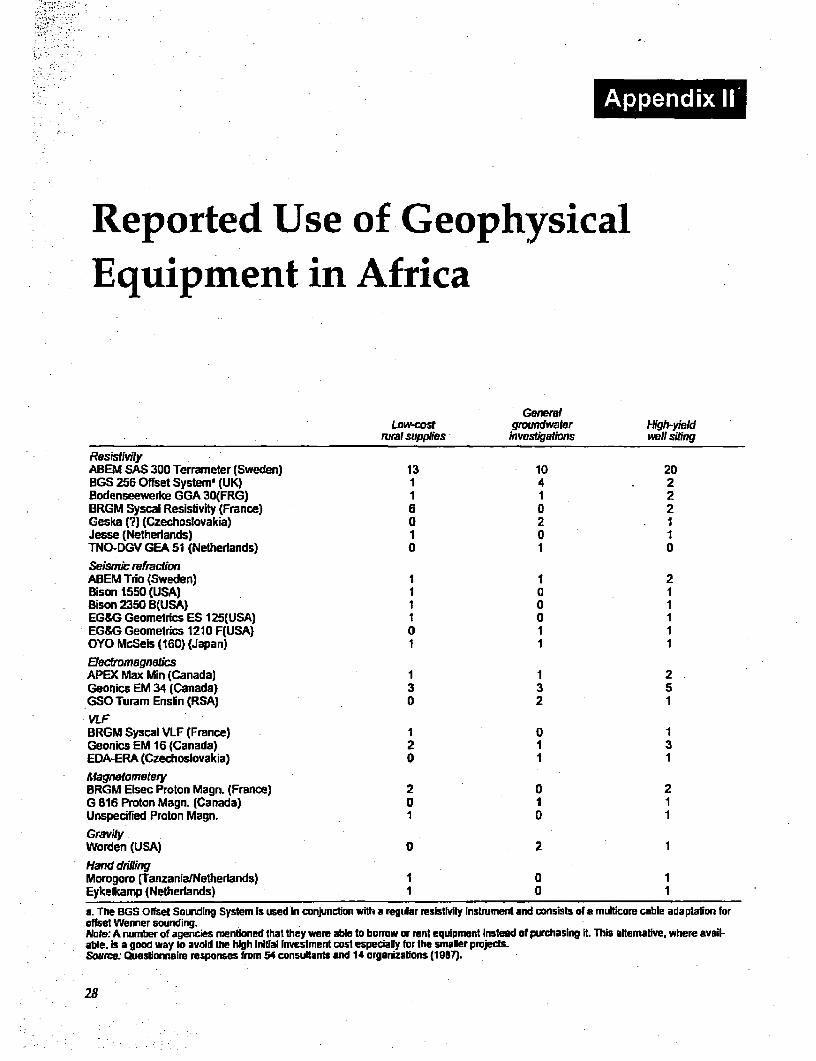
Reported Use of GeophysicalEquipment in Africa
GeneralLow-cost groundwater High-yield
rural supplies investigations well siting
Res.st.vityABEM SAS 300 Terrameter (Sweden) 13 10 20BGS 256 Offset Systema (UK) 1I 4 . 2Bodenseewerke GGA 30(FRG) 1 1 2BRGM Syscal Resistivity (France) 6 a 2Geska (?3 (Czechoslovakia) 0 2 1Jesse (Netherlands) 1 0 1TNO-DGV GEA 51 (Netherlands) 0 1 0Seismic refractionAB3EM Trio (Sweden) 1 1 2Bison 1550 (USA) I (I 1Bison 2350 B(USA) 1 0 1EG&G Geometrics ES 125(USA) I 0 1EG&G Geometries 121 0 F(USA) 0 1 1OYO MaSeis (160) (Japan) 1 1 1E.ed'magnetksAPEX Max Min (Canada) 1 1 2Geonics EM 34 (Canada) 3 3 5GSO Turam Enslin (RSA) 0 2 1VLFBRGM Syscal VLF (France) 1 0 1Geonics EM 16 (Canada) 2 1 3EDA-ERA (Czechoslovakia) 0 1 1MfagnetonetwlyBRGM Elsec Proton Magn. (Franice) 2 0 2G 816 Proton Magn. (Canada) 0 1 1Unnspecified Proton Magn. 1 0 1GravityWarden (USA) 0 2 1Hand dnhilingMorogoro (TanzanialNetherlands) 1 0 1Eykelkamp (Netherlands) 1 0 1
a. The BGS Offset Sounding Systemi is used In conjunction with a regular resistivity Instrunent and consists of a multicor cable adaptation forafset Wenner sounding.Nate:, A number of agencies mentioned that they were able to borrow or rent equipment instead of purchasing Rt. This alternative, where avail-able. is a good way to avoid the high Initial Investment cost espedially for the smaller projects-Source., Questionnaime responses from 54 consultants and 14 organizations (19B7).
28
References
Alt, I-L.0.1987. "Geophysical Mapping of a Buried Farr, J.L., P.R. Spray, and S.S.D. Foster. 1982.Basalt/Sedimnentary Interface, Eastern Sudan." "Groundwater Supply Exploration in Semi-AridGrounid Water 25(1)1:14-20. Regions for Livestock Extension: A Technical and
Artosoroff, S., et al. 1987. Com-nunity Water Supply. Economic Appraisal." Water Supply and Manage-7The Handpump Option. Washington DC. The mett 6:343-53.
World Bank. Penner, TJI. 1985. Applications of Subsurface Inter-Barker, R.D. 1981. "The Offset System of Electrical face Radar in Limestone. Hudson, NH: Geophysi-
Resistivity Sounding and Its Use with a Multicore cal Survey Systems, Inc.Cable." Geophysical Prospectinig 29:128-43. Foster, SS.D. 1984. "African Groundwater Develop-
1985. "Offset Spacing Aids Resistivity Work." ment: The Challenges for Hydrogeological 56-World Watter 8(9):47-48. ence." In Walling, et al. eds., 1984,3-12.
Beale, G. 1986. "Groundwork and Groundwater." Grey, D.R.C., et al. 1985. "The Expanding Role of theAfrican Techinical Review June:67-68. Hydrogeologist in the Provision of Village Water
Blankwaardt, B. 1984. Hand Drilled Wells: A Matnual Supplies: An African Perspective." Quarterlyon Sitinig, Design, Construction anid Maintenance. Journal of Engineering Geology 18:13-24.Oar es Salaaim: Rwegarulia Water Resources Hydrotechnica. 1985. Accelerated Drought ReliefIrtstitute. Programme. Victoria Province (Vol. 1-7). Govern-
Chilton, Pj1. anid A.K. Smnith-Carington. 1984. "Char- ment of the Republic of Zimnbabwe. Europeanacteristics of the Weathered Basemient Aquifer in Economic Commnunity.Malawi in Relation to Rural Water Supplies." hin Luonsi, A. and P. Lappalainen. 1981. GeophysicalWalling, et al., 1984,57-72. Methods Applied to Ground Water Exploration in
DHV. 1978. Shallow Wells. Amersfoort, the Nether- South-East Tanzania. Helsinki: Tampere Urniver-lands: DHV Consulting Engineers. shty of Technology. Report 8.
Doberki, T.L. and P.R. Ronilg.1985. "Geotechnical Mathiez, J.P. and G. Hluot. 1968. Geophysical Pros-and Groundwater Geophysics" Geophysics pecting and Ground Water Exploration: Examplees50(12):221-36. ofAppliction in West Africa. Paris: Interafncan
EROS Data Center. User Services: Sioux Falls, SD Committee for Hydrologic Studies.57198 USA. Mfijne, M.A.J. n.d. Present Development of the Bia-
European Space Agency, Earthnet User Services: Via physical Method Applied to Geoexplomation.Galileo Galilei, 000 44 Frascati Italy. Regional jeddah, Saudi Arabia.-Centre for Services in Surveying, Mapping and . n A. T'he Biophysical Method. Jeddah, SaudiRemnote Sensing. Box 18118, Nairobi, Kenya. Spot Arabia.Image: 16 his, Avenue Edouard-Benin, B?P. 4359, Norwegian Church Aid Sudan Programmne. Water31030 Toulouse cedex, France. Project. Summary Report 1975-84. Nairobi: NCA,
1985.
29
I FINDING GROUNDWATER: A PROJECT MANAGER'S GUIDE TO TECHNIQUES AND How TO USE THEM
Ovaskainen, E. 1984. Study on the Use of Refraction Electrical Resistivity, Seismic Refraction, andSeismic Surney in Siting of Borehole Wells int the Gravity Measurements for Groundwater Explora-Area of South Kordofan, Sudan. Kefinco, Kenya; tion in Sudan-" Geophlysics 46(9):1,304-13.UNICEF, Sudan. . 1980. "Tracing by Gravity of a Narrow
n.d. Case Study oftthe Use of Refraction Buried Graben Structure, Detected by SeismicSeismic Sureysfor the Siting of Boreholesfor Refraction, for Ground-Water Investigation inHandpumped Supplies in Western Province, North Chile." Geophysical Prospecting 2B(3):392-Kenya. Kakamega, Kenya. 407]
LPalacky, G.J. 1981. "The Airborne Electromagnetic .1975. "A Combination of Gravity and Seis-Method as a Tool of Geological Mapping." Geo- mic Refraction Measurements, Applied tophysica Prospecting 29:60-88. Groundwater Exploratiors Near Taltal, Province
Paterson, NR., and RA. BosscharL 1987. "Airbome of Antofagsta, Chile." Geophiysical ProspectingGeophysical Exploration for Groundwater." 23(2):248-58.Ground Water 25(l):41-50. van Wjk, C. and J.T. Visscher. 1987. "Handpump
Pulawski, B., and K. Klitten. n.d. Combined Use of Projects: Avoiding Neglect!' World WaterResistivity and Seismic Refraction Methods in 10(4).44-46.Groundwater Prospecting in Crystalline Areas. Williamson, T. 1987. "A Sense of Direction for Dows-Study Project, Kenya 1977. Danish International ers?' Naq Scientist March 19.Development Agency (DANIDA); Cowiconsult; WRAP. 1984a. Water Resources Assessment StudyInstitute for Applied Geology, Technical Univer- Kerio Valley (Elgeyo Marakwet and Baringosity of Denmark. Districts). Main Report. Nairobi: Ministry of Water
Schleberger, E. 1986. Drinking Water Supply and Development, Groundwater Survey TNO.Sanitation Project in Sri Lana. Eschbom: GTZ .1984b. Water Resources Assessment StudyGrmb]L West Pokot District. Main Report. Nairobi: Minis-
Sir M. MacDonald and Partners Ltd. 1986. Rural try of Water Development, Groundwater SurveyWater Supplies. Final Report (VoL 1-4. Federal TNO.Republic of Nigeria. Kano State Agricultural and - 1987a. W^Jater Resources Assessment Study inRural Development Authority. Baringo District. Main Report. Nairobi: Ministry of
Smith-Carington, AK. and P.J. Chilton. 1983. The Water Development, TNO-DGV istitute of Ap-Groundwater Resources of Malawi. Lilongwe: plied Geoscence.Malawi Government. .1987b. Water Resources Assessment Study in
van Lissa, RV., HRJ. van Maanen, and F.W. Odera. Lakipia Distrct. Mtain Report Nairobi: Ministry of1987. "The Use of Remote Sensing and Geophysics Water Development, TNO-DGV Institute of Ap-for Groundwater Exploration in Nyanza Province, plied Geoscience.Kenya." Lake Basin Development Authority, DHV Wright, D.L, G.R. Olhoeft, and RD. Watts. n.d.Consulting Engineers, the Netherlands. Ground-Penetrating Radar Studies on Cape Cod.
van Overmeeren, RA. 1981. "A Combination of Hudson, NIH Geophysical Survey Systems, Inc.
30