ingleside stephen a.tat ... presentation/tat-final...• underground parking • roof gardens...
TRANSCRIPT

Structural Option 2008-2009Ingleside AT KING FARM
An Architectural Engineering Senior Thesis
STEPHEN A. TAT
Introduction
Structural Depth
Thesis Statement
Existing Condition
Breadth Study I
Breadth Study II
Conclusion

Project Profile
Location and Site: 701 King Farm Blvd. Rockville, MD 20852Building Occupant Name: Elderly Residents and Nurses
Occupancy or function types: CCRC (Continuous Care Retirement Center)Size: 790,000 SF
Height: 103 feet, 7 above grade, 1 below grade.Construction Dates: Nov 1, 2006 to Match 2009
Delivery method: CM AgencyBid Cost: GMP of $97 Million
Structural Option 2008-2009Ingleside AT KING FARM
An Architectural Engineering Senior Thesis
STEPHEN A. TAT
Project Team
Owner:Ingleside Presbyterian Retirement Community
Architect and Landscape Architect:Cochran, Stephenson & Donkervoet, Inc.
General Contractor:Turner Construction Company
Construction Manager:Turner‐Konover
Structural Engineer:Morabito Consultants, Inc.
INTRODUCTIONTHESIS
STATEMENTBREADTH I BREADTH II CONCLUSION
STRUCTURAL DEPTH
EXISTING CONDITION
Structural Depth
Introduction
Thesis Statement
Existing Condition
Breadth Study I
Breadth Study II
Conclusion
INTRODUCTIONTHESIS
STATEMENTBREADTH I BREADTH II CONCLUSION
STRUCTURAL DEPTH
EXISTING CONDITION
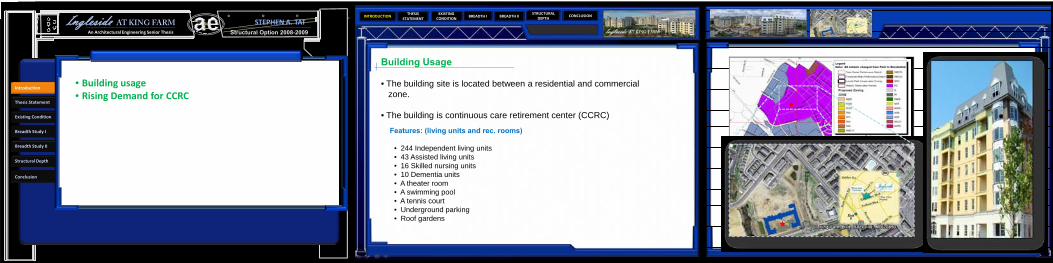
Building Usage
• The building site is located between a residential and commercialzone.
• The building is continuous care retirement center (CCRC)
Features: (living units and rec. rooms)
• 244 Independent living units • 43 Assisted living units • 16 Skilled nursing units • 10 Dementia units • A theater room • A swimming pool • A tennis court • Underground parking • Roof gardens
Structural Option 2008-2009Ingleside AT KING FARM
An Architectural Engineering Senior Thesis
STEPHEN A. TAT
Structural Depth
Introduction
Thesis Statement
Existing Condition
Breadth Study I
Breadth Study II
Conclusion
• Building usage• Rising Demand for CCRC
INTRODUCTIONTHESIS
STATEMENTBREADTH I BREADTH II CONCLUSION
STRUCTURAL DEPTH
EXISTING CONDITION
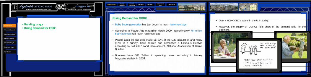
Rising Demand for CCRC
• Baby Boom generation has just begun to reach retirement age.
• According to Future Age magazine March 2009, approximately 78 millionbaby boomers will reach retirement age.
• People aged 50 and over made up 12% of the U.S. population and many(37% in a survey) have desired and demanded a luxurious lifestyleaccording to Fall 2007 Land Development, National Association of HomeBuilders.
• Boomers have $21 Trillion in spending power according to MoneyMagazine statistic in 2005.
• Over 4,000 CCRCs exists in the U.S. today.
• However, the supply of CCRCs falls short of the demand side for theBoomers.
Structural Option 2008-2009Ingleside AT KING FARM
An Architectural Engineering Senior Thesis
STEPHEN A. TAT
Structural Depth
Introduction
Thesis Statement
Existing Condition
Breadth Study I
Breadth Study II
Conclusion
• Building usage• Rising Demand for CCRC
INTRODUCTIONTHESIS
STATEMENTBREADTH I BREADTH II CONCLUSION
STRUCTURAL DEPTH
EXISTING CONDITION
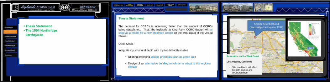
Thesis Statement
The demand for CCRCs is increasing faster than the amount of CCRCsbeing established. Thus, the Ingleside at King Farm CCRC design will beused as a model for a new prototype design on the west coast of the UnitedStates.
Other Goals
Integrate my structural depth with my two breadth studies
• Utilizing emerging design principles such as green built
• Design of an alternative building envelope to adapt to the region’sclimate
Reseda Neighborhood (Northridge Earthquake 1994)
LA
Relocation on the West Coast
Los Angeles, California
• Site conditions will affect breadth studies and structural depth
Structural Option 2008-2009Ingleside AT KING FARM
An Architectural Engineering Senior Thesis
STEPHEN A. TAT
Structural Depth
Introduction
Thesis Statement
Existing Condition
Breadth Study I
Breadth Study II
Conclusion
• Thesis Statement• The 1994 Northridge Earthquake

INTRODUCTIONTHESIS
STATEMENTBREADTH I BREADTH II CONCLUSION
STRUCTURAL DEPTH
EXISTING CONDITION
The 1994 Northridge Earthquake
• Occurred on Jan. 17, 1994• Lasting for about 20 seconds• Moment magnitude of 6.7• $20 billion in damage
Blind thrust faults: exist near tectonic plate margins, in the broad disturbance zone. They form when a section of the earth's crust is under high compressive stresses, due to plate margin collision, or the general geometry of how the plates are sliding past each other.
Although usually of magnitude 6 to 7 compared to the largest magnitude 9 earthquakes of recent times, it was especially destructive because the seismic waves are highly directed, and the soft basin soil of the valley can amplify the ground motions tenfold or more
Structural Option 2008-2009Ingleside AT KING FARM
An Architectural Engineering Senior Thesis
STEPHEN A. TAT
Structural Depth
Introduction
Thesis Statement
Existing Condition
Breadth Study I
Breadth Study II
Conclusion
• Thesis Statement• The 1994 Northridge Earthquake
INTRODUCTIONTHESIS
STATEMENTBREADTH I BREADTH II CONCLUSION
STRUCTURAL DEPTH
EXISTING CONDITION
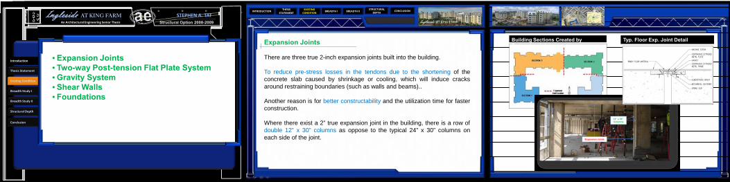
Expansion Joints
There are three true 2-inch expansion joints built into the building.
To reduce pre-stress losses in the tendons due to the shortening of theconcrete slab caused by shrinkage or cooling, which will induce cracksaround restraining boundaries (such as walls and beams)..
Another reason is for better constructability and the utilization time for fasterconstruction.
Where there exist a 2” true expansion joint in the building, there is a row ofdouble 12” x 30” columns as oppose to the typical 24” x 30” columns oneach side of the joint.
Building Sections Created by Expansion Joints
Expansion Joints
12” x 30” Columns
Typ. Floor Exp. Joint Detail
Structural Option 2008-2009Ingleside AT KING FARM
An Architectural Engineering Senior Thesis
STEPHEN A. TAT
Structural Depth
Introduction
Thesis Statement
Existing Condition
Breadth Study I
Breadth Study II
Conclusion
• Expansion Joints• Two-way Post-tension Flat Plate System• Gravity System• Shear Walls• Foundations

INTRODUCTIONTHESIS
STATEMENTBREADTH I BREADTH II CONCLUSION
STRUCTURAL DEPTH
EXISTING CONDITION
Two-way Post-tension Flat Plate System
270 ksi unbonded ½ diameter 7 wire tendons.
Concrete slabs are 8 inches thick for typical floors with a compressive strength of 4500 psi.
Irregular column gird of the building
Bays range from 15 feet to 29.5 feet.
Typical Tendon Support Bars
Structural Option 2008-2009Ingleside AT KING FARM
An Architectural Engineering Senior Thesis
STEPHEN A. TAT
Structural Depth
Introduction
Thesis Statement
Existing Condition
Breadth Study I
Breadth Study II
Conclusion
• Expansion Joints• Two-way Post-tension Flat Plate System• Gravity System• Shear Walls• Foundations

INTRODUCTIONTHESIS
STATEMENTBREADTH I BREADTH II CONCLUSION
STRUCTURAL DEPTH
EXISTING CONDITION
Gravity System
Over 140 reinforced columns, are either 18” x 30” or 12” x 30”.
Shear Walls
Seven of the walls are ordinary reinforced concrete shear walls located atstairwells and elevator shafts with #4 horizontal reinforcing bars and #8vertical reinforcing bars. Typical spacing of these bars is 12 inches.
The remaining four reinforced concrete shear walls have boundaryelements and are 15 feet in length; two in east/west direction and two innorth/south direction. Spacing of vertical and horizontal reinforcements is30 inches and 12 inches respectively. Typical clear cover is 1 ½ inches forthe reinforcements.
Structural Option 2008-2009Ingleside AT KING FARM
An Architectural Engineering Senior Thesis
STEPHEN A. TAT
Structural Depth
Introduction
Thesis Statement
Existing Condition
Breadth Study I
Breadth Study II
Conclusion
• Expansion Joints• Two-way Post-tension Flat Plate System• Gravity System• Shear Walls• Foundations

INTRODUCTIONTHESIS
STATEMENTBREADTH I BREADTH II CONCLUSION
STRUCTURAL DEPTH
EXISTING CONDITION
Foundations
• The loads from above are transferred down by 30” x 18” reinforced concrete columns with10 #8 bars to spread footings of various sizes.
• Beneath the spread footings is 3 feet of compact fill and soil with a bearing capacity of 50ksf.
• The structural slab in the foundation and sub level parking garage is a 5” concrete slab ongrade reinforced with 6” x 6” W2.9 / W2.9 welded wire fabric over a vapor barrier and a 4”porous fill. It utilizes standard weight concrete with a 28 day minimum compressivestrength of 4000 psi.
• 40% of the footings are sized 10’- 6” x 10’- 6” x 30” with 10 # 8 E. W. reinforcing bars atthe bottom;
• 20% of the footings are sized 12’ x 12’ x 34” with 10 # 9 E. W. reinforcing bars at thebottom;
• All shear walls are designed with much larger spread footings typically 20’ x 28’ x 30” with22 # 9 S.W. and 16 # 9 L.W. top and bottom.
Structural Option 2008-2009Ingleside AT KING FARM
An Architectural Engineering Senior Thesis
STEPHEN A. TAT
Structural Depth
Introduction
Thesis Statement
Existing Condition
Breadth Study I
Breadth Study II
Conclusion
• Expansion Joints• Two-way Post-tension Flat Plate System• Gravity System• Shear Walls• Foundations
INTRODUCTIONTHESIS
STATEMENTBREADTH I BREADTH II CONCLUSION
STRUCTURAL DEPTH
EXISTING CONDITION
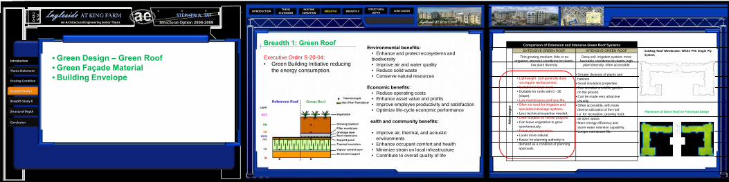
Comparison of Extension and Intensive Green Roof SystemsEXTENSIVE GREEN ROOF INTENSIVE GREEN ROOF
Thin growing medium; little or no irrigation; stressful conditions for plants;
low plant diversity
Deep soil; irrigation system; more favorable conditions for plants; high
plant diversity; often accessible
Adva
ntag
es
• Lightweight; roof generally does not require reinforcement.
• Suitable for large areas.• Dutiable for roofs with 0 - 30(slope).
• Low maintenance and long life.• Often no need for irrigation and specialized drainage systems.
• Less technical expertise needed.• Often suitable for retrofit projects.• Can leave vegetation to grow spontaneously.
• Relatively inexpensive.• Looks more natural.• Easier for planning authority to demand as a condition of planning approvals.
• Greater diversity of plants and habitats.
• Good insulation properties.• Can simulate a wildlife garden on the ground.
• Can be made very attractive visually.
• Often accessible, with more diverse utilization of the roof. i.e. for recreation, growing food, as open space.
• More energy efficiency and storm water retention capability.
• Longer membrane life.
Breadth 1: Green Roof
Executive Order S-20-04: • Green Building Initiative reducing
the energy consumption.
Environmental benefits:• Enhance and protect ecosystems and biodiversity • Improve air and water quality • Reduce solid waste • Conserve natural resources
Economic benefits: • Reduce operating costs • Enhance asset value and profits • Improve employee productivity and satisfaction • Optimize life-cycle economic performance
Health and community benefits:
• Improve air, thermal, and acoustic environments
• Enhance occupant comfort and health • Minimize strain on local infrastructure • Contribute to overall quality of life
Structural Option 2008-2009Ingleside AT KING FARM
An Architectural Engineering Senior Thesis
STEPHEN A. TAT
Structural Depth
Introduction
Thesis Statement
Existing Condition
Breadth Study I
Breadth Study II
Conclusion
• Green Design – Green Roof• Green Façade Material• Building Envelope
Existing Roof Membrane: White PVC Single PlySystem
Placement of Green Roof on Prototype Design
INTRODUCTIONTHESIS
STATEMENTBREADTH I BREADTH II CONCLUSION
STRUCTURAL DEPTH
EXISTING CONDITION
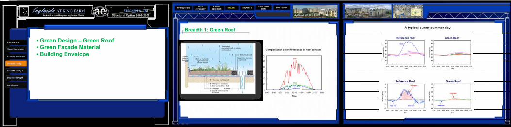
Breadth 1: Green Roof
Structural Option 2008-2009Ingleside AT KING FARM
An Architectural Engineering Senior Thesis
STEPHEN A. TAT
Structural Depth
Introduction
Thesis Statement
Existing Condition
Breadth Study I
Breadth Study II
Conclusion
• Green Design – Green Roof• Green Façade Material• Building Envelope
INTRODUCTIONTHESIS
STATEMENTBREADTH I BREADTH II CONCLUSION
STRUCTURAL DEPTH
EXISTING CONDITION
Breadth 1: Green Roof
Structural Option 2008-2009Ingleside AT KING FARM
An Architectural Engineering Senior Thesis
STEPHEN A. TAT
Structural Depth
Introduction
Thesis Statement
Existing Condition
Breadth Study I
Breadth Study II
Conclusion
• Green Design – Green Roof• Green Façade Material• Building Envelope
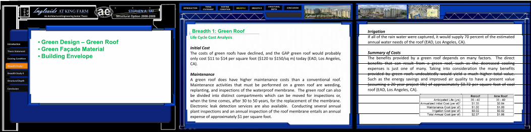
Life Cycle Cost Analysis
Initial CostThe costs of green roofs have declined, and the GAP green roof would probablyonly cost $11 to $14 per square foot ($120 to $150/sq m) today (EAD, Los Angeles,CA).
MaintenanceA green roof does have higher maintenance costs than a conventional roof.Maintenance activities that must be performed on a green roof are weeding,replanting, and inspections of the waterproof membrane. The green roof can alsobe divided into distinct compartments which can be moved for inspections or,when the time comes, after 30 to 50 years, for the replacement of the membrane.Electronic leak detection services are also available. Conducting several annualplant inspections and an annual inspection of the roof membrane entails an annualexpense of approximately $1 per square foot.
IrrigationIf all of the rain water were captured, it would supply 70 percent of the estimatedannual water needs of the roof (EAD, Los Angeles, CA).
Summary of CostsThe benefits provided by a green roof depends on many factors. The directbenefits that can result from a green roof, such as the decreased coolingexpenses is just one of many. Taking into consideration the many benefitsprovided by green roofs undoubtedly would yield a much higher total value.Such as the energy savings and improved air quality to have a present value(assuming a 20 year project life) of approximately $0.72 per square foot of coolroof (EAD, Los Angeles, CA).

INTRODUCTIONTHESIS
STATEMENTBREADTH I BREADTH II CONCLUSION
STRUCTURAL DEPTH
EXISTING CONDITION
Structural Option 2008-2009Ingleside AT KING FARM
An Architectural Engineering Senior Thesis
STEPHEN A. TAT
Structural Depth
Introduction
Thesis Statement
Existing Condition
Breadth Study I
Breadth Study II
Conclusion
• Green Design – Green Roof• Green Façade Material• Building Envelope
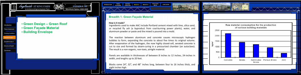
Breadth 1: Green Façade Material
Use AUTOCLAVED AERATED CONCRETE (AAC) ‐ green material
Seismic design
• The light weight of AAC in relation to its strength reduces the base shear.
• Fire‐resistant characteristics provide further advantage against fires commonly associated with earthquakes. (4” thick panel gives UL fire rating of 4 hours)
Building Envelope Benefits
• High durability = less maintenance, good life cycle cost• Rapid construction and good workability = reduced labor• Excellent thermal insulation• Excellent sound absorption• Lighter than light weight concrete (~80% air)
INTRODUCTIONTHESIS
STATEMENTBREADTH I BREADTH II CONCLUSION
STRUCTURAL DEPTH
EXISTING CONDITION
Breadth 1: Green Façade Material
How is it made?
Structural Option 2008-2009Ingleside AT KING FARM
An Architectural Engineering Senior Thesis
STEPHEN A. TAT
Structural Depth
Introduction
Thesis Statement
Existing Condition
Breadth Study I
Breadth Study II
Conclusion
• Green Design – Green Roof• Green Façade Material• Building Envelope
Ingredients used to make AAC include Portland cement mixed with lime, silica sand,or recycled fly ash (a byproduct from coal‐burning power plants), water, andaluminum powder or paste and the mixed is poured into a mold.
The reaction between aluminum and concrete causes microscopic hydrogenbubbles to form, expanding the concrete to about five times its original volume.After evaporation of the hydrogen, the now highly closed‐cell, aerated concrete iscut to size and formed by steam‐curing in a pressurized chamber (an autoclave).The result is a non‐organic, non‐toxic, airtight material.
Panels are available in thicknesses of between 8 inches to 12 inches, 24‐inches inwidth, and lengths up to 20 feet.
Blocks come 24”, 32”, and 48” inches long, between four to 16 inches thick, andeight inches high.

INTRODUCTIONTHESIS
STATEMENTBREADTH I BREADTH II CONCLUSION
STRUCTURAL DEPTH
EXISTING CONDITION
Building Envelope:
The roof membrane is a 3” rigid insulation on 1 ½” x 20 gauge galvanized metal decksupported by either 26 k12 or 28 k12 joists depending on the roof loads with anassembly consisting of 8” post tension slab and membrane roof water proofing system.
The 7th floor building envelope consist of a sloped roof assemble (mansard roof style)characterized by dark colored metal shingles on plywood roof sheathing and 4" metalstud framing.
On the 6th floor, the exterior veneer brick is replaced by a light-beige stucco with areinforcing mesh behind it.
The mid section of the building (2nd to 5th floor) is similar to the base section exceptthat masonry brick is used in place of the cast stones.
The base consist of 16x24 cast stones. It is followed by an air space, ½” sheathing,masonry veneer ties at 16” O.C., 6” steel studs at 16” O.C., 6” batt insulation at an Rvalue of 19 and 5/8” foil face gypsum board.
Structural Option 2008-2009Ingleside AT KING FARM
An Architectural Engineering Senior Thesis
STEPHEN A. TAT
Structural Depth
Introduction
Thesis Statement
Existing Condition
Breadth Study I
Breadth Study II
Conclusion
• Green Design – Green Roof• Green Façade Material• Building Envelope

INTRODUCTIONTHESIS
STATEMENTBREADTH I BREADTH II CONCLUSION
STRUCTURAL DEPTH
EXISTING CONDITION
Breadth 2: Building Envelope Redesign
• Use light weight precast architectural panels to reduce building weight, which in turn reduce the base shear of the building, but still conserve the aesthetics of the original cavity wall design..
• Address structural integrity and code compliances such as cladding issues and strength issues.
• Analyze air and moisture permeability, and thermal comfort provided by the recommended envelope assembly.
Structural Option 2008-2009Ingleside AT KING FARM
An Architectural Engineering Senior Thesis
STEPHEN A. TAT
Structural Depth
Introduction
Thesis Statement
Existing Condition
Breadth Study I
Breadth Study II
Conclusion
• Building Envelope Redesign• Building Envelope Analysis
DeflectionThe allowable lateral deflectionof AERCON wall panels due tolateral load is L/240. In most cases, an 6" thick wall panel is sufficient to resist the design loads in L.A. as wind is not a factor (85 mph per ASCE‐07)
6”

INTRODUCTIONTHESIS
STATEMENTBREADTH I BREADTH II CONCLUSION
STRUCTURAL DEPTH
EXISTING CONDITION
Breadth 2: Building Envelope Redesign
Structural Option 2008-2009Ingleside AT KING FARM
An Architectural Engineering Senior Thesis
STEPHEN A. TAT
Structural Depth
Introduction
Thesis Statement
Existing Condition
Breadth Study I
Breadth Study II
Conclusion
• Building Envelope Redesign• Building Envelope Analysis
The following cavity wall assembly was designed for the prototype:
• Exterior Autoclaved Aerated Concrete Panels ‐ 6.0 inch thick• Air space and drainage plane ‐ 2.5 inch• Paper stand ‐ 8 mil• Plywood sheathing ½ inch• Rigid insulation ‐ 2 inch• Steel Studs ‐5 ½ inch• And gypsum board ‐ ½ inch
The material is available in masonry units and precast panels. The usage of asingle material with various appearance can reduce the amount of façadeinterfaces that is in the existing design of Ingleside at King Farm. This willdecrease the chances of infiltration and moisture penetration into the structureand conditioned spaces.
INTRODUCTIONTHESIS
STATEMENTBREADTH I BREADTH II CONCLUSION
STRUCTURAL DEPTH
EXISTING CONDITION
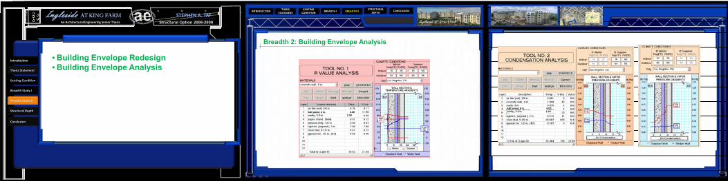
Breadth 2: Building Envelope Analysis
Structural Option 2008-2009Ingleside AT KING FARM
An Architectural Engineering Senior Thesis
STEPHEN A. TAT
Structural Depth
Introduction
Thesis Statement
Existing Condition
Breadth Study I
Breadth Study II
Conclusion
• Building Envelope Redesign• Building Envelope Analysis
AAC panel, 6 in. 6.00 cavity , 2.5 in. 2.50
AAC panel, 6 in. 6.00 cavity , 2.5 in. 2.50

INTRODUCTIONTHESIS
STATEMENTBREADTH I BREADTH II CONCLUSION
STRUCTURAL DEPTH
EXISTING CONDITION
Breadth 2: Building Envelope Redesign
The most common moisture protection system used with precast concrete wall systems is a barrier system incorporating an adequate joint seal. In some cases where additional moisture protection is needed, the application of a sealer or a concrete coating is also used
Structural Option 2008-2009Ingleside AT KING FARM
An Architectural Engineering Senior Thesis
STEPHEN A. TAT
Structural Depth
Introduction
Thesis Statement
Existing Condition
Breadth Study I
Breadth Study II
Conclusion
• Building Envelope Redesign• Building Envelope Analysis
Seismic codes require that heavy panels accommodate movement either by sliding or ductile connections. In high seismic zones a ductile connection will be utilized in the prototype design of Ingleside at King Farm. One type of ductile connection is a "Push‐pull“ ‐ with Bearing connection at top, tieback connection at bottom.

INTRODUCTIONTHESIS
STATEMENTBREADTH I BREADTH II CONCLUSION
STRUCTURAL DEPTH
EXISTING CONDITION
Goals and Criteria
Goals:
• Utilize a steel structural system• Preserve existing architectural design (Plans, story heights, aesthetics)• Optimize lateral system
Codes and Standards:
• Meet seismic design criteria• Strength design• Serviceability requirements• State/local codes (LOS ANGELES REGIONAL UNIFORM CODE PROGRAM
(LARUCP))
Load Combinations:All are based on LRFD design method
1.4(D + F)1.2(D + F + T) + 1.6(L + H) + 0.5(Lr or S
or R)1.2D + 1.6(Lr or S or R) + (L or 0.8W)1.2D + 1.6W + L + 0.5(Lr or S or R)1.2D + 1.0E + L + 0.2S0.9D + 1.6W + 1.6H0.9D + 1.0E + 1.6H
Structural Option 2008-2009Ingleside AT KING FARM
An Architectural Engineering Senior Thesis
STEPHEN A. TAT
Structural Depth
Introduction
Thesis Statement
Existing Condition
Breadth Study I
Breadth Study II
Conclusion
• Goals and Criteria• Placement of Expansion Joints• Expansion Joints Specified by Code• Floor System Design• Lateral Design• Seismic Analysis
Codes, Standards, and Guides
Codes and Standards in Original DesignCodes and Standards used for Prototype
DesignInternational Building Code 2003 International Building Code 2006ASCE 7-98: Minimum Design Loads For Buildings and other Structures.
ASCE 7-05: Minimum Design Loads For Buildings and other Structures.
Rockville, MD City Codes: Local amendments.
American Institute of Steel Construction (AISC) 13th Edition
AISC Seismic Design Manual
AISC –LRFD 1999, Load and Resistance Factor Design Specification for StructuralSteel BuildingsVulcraft Steel Roof and Deck Catalog
2007 California Building Code Section 1614ACI 318-08 Building Code Requirements for Structural Concrete
PCI Design Handbook - Precast and Prestressed Concrete
Architectural Precast Concrete (2nd
ed.) IBC 2006 Structural/Seismic Design Manual: Building Design Examples for Steel and Concrete.
INTRODUCTIONTHESIS
STATEMENTBREADTH I BREADTH II CONCLUSION
STRUCTURAL DEPTH
EXISTING CONDITION
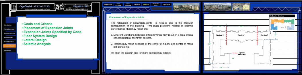
Placement of Expansion Joints
The relocation of expansion joints is needed due to the irregularconfiguration of the building. Two main problems related to seismicperformance that may result are:
1. Different vibrations between different wings may result in a local stressconcentration at reentrant corners.
2. Torsion may result because of the center of rigidity and center of massnot coinciding.
Re align the column grid for more consistency in bays
148’
281’
136’
90’
66’
135’
In Existing Structure
Structural Option 2008-2009Ingleside AT KING FARM
An Architectural Engineering Senior Thesis
STEPHEN A. TAT
Structural Depth
Introduction
Thesis Statement
Existing Condition
Breadth Study I
Breadth Study II
Conclusion
• Goals and Criteria• Placement of Expansion Joints• Expansion Joints Specified by Code• Floor System Design• Lateral Design• Seismic Analysis

INTRODUCTIONTHESIS
STATEMENTBREADTH I BREADTH II CONCLUSION
STRUCTURAL DEPTH
EXISTING CONDITION
• Expansion Joints Specified by Code
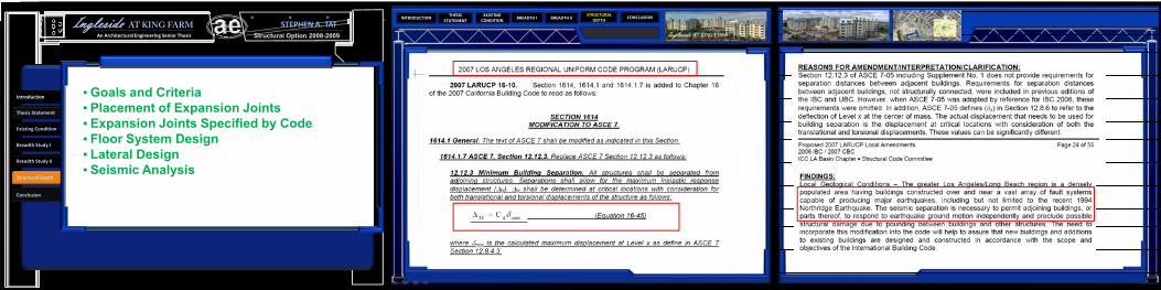
450 feet
As for normal temperature change, the average daily change is approximately 20 F.According to a graph in the AISC Steel Construction Manual, the allowable buildinglength for a steel constructed building is approximately 450 feet for a temperaturechange of 60 F. The max distance of a building section as a result of my proposedexpansion joint placements is no greater than 281 feet. This meets the design lengthcriteria.
As for minimum building separation (of adjoining structures), L.A , California hadmodified ASCE 7 in Section 1614 in the 2007 California Building Code to allow for themaximum inelastic response displacement :
ΔM = Cdδmax (equation 16‐45).
Where δmax is the calculated maximum displacement at Level x as define in ASCE 7Section 12.8.4.3.
ASCE 7‐05 Minimum DesignLoads for Buildings andOther Structures states,“Dimensional changes in astructure and its elementsdue to variations intemperature, relativehumidity, or other effectsshall not impair theserviceability of thestructure.”
Structural Option 2008-2009Ingleside AT KING FARM
An Architectural Engineering Senior Thesis
STEPHEN A. TAT
Structural Depth
Introduction
Thesis Statement
Existing Condition
Breadth Study I
Breadth Study II
Conclusion
• Goals and Criteria• Placement of Expansion Joints• Expansion Joints Specified by Code• Floor System Design• Lateral Design• Seismic Analysis
INTRODUCTIONTHESIS
STATEMENTBREADTH I BREADTH II CONCLUSION
STRUCTURAL DEPTH
EXISTING CONDITION
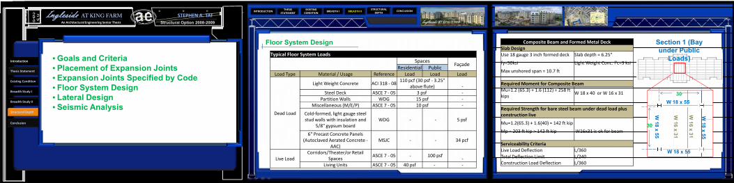
Floor System Design Composite Beam and Formed Metal Deck Slab DesignUse 18 gauge 3 inch formed deck Slab depth = 6.25"
fy=50ksi Light Weight Conc: f'c=3 ksi
Max unshored span = 10.7 ft
Required Moment for Composite BeamMu=1.2 (65.3) + 1.6 (112) = 258 ft kips
W 18 x 40 or W 16 x 31
Required Strength for bare steel beam under dead load plus construction live
Mu=1.2(65.3) + 1.6(40) = 142 ft kip
Mp = 203 ft kip > 142 ft kip W16x31 is ok for beam
Serviceability CriteriaLive Load Deflection L/360 Total Deflection Limit L/240 Construction Load Deflection L/360
30’
30’
W 18 x 55
W 18 x 55
W 18 x 55
W 18 x 55
W 16 x 31
W 16 x 31
Section 1 (Bay under Public
Loads)
30’
Typical Floor System LoadsSpaces
FaçadeResidential Public
Load Type Material / Usage Reference Load Load Load
Dead Load
Light Weight Concrete ACI 318 ‐ 08110 pcf (30 psf ‐ 3.25"
above flute) ‐Steel Deck ASCE 7 ‐ 05 3 psf ‐
Partition Walls WDG 15 psf ‐Miscellaneous (M/E/P) ASCE 7 ‐ 05 10 psf ‐
Cold‐formed, light gauge steel stud walls with insulation and
5/8" gypsum boardWDG ‐ ‐ 5 psf
6" Precast Concrete Panels (Autoclaved Aerated Concrete ‐
AAC)MSJC ‐ ‐ 34 pcf
Live LoadCorridors/Theater/or Retail
SpacesASCE 7 ‐ 05 ‐ 100 psf
‐Living Units ASCE 7 ‐ 05 40 psf ‐ ‐
Structural Option 2008-2009Ingleside AT KING FARM
An Architectural Engineering Senior Thesis
STEPHEN A. TAT
Structural Depth
Introduction
Thesis Statement
Existing Condition
Breadth Study I
Breadth Study II
Conclusion
• Goals and Criteria• Placement of Expansion Joints• Expansion Joints Specified by Code• Floor System Design• Lateral Design• Seismic Analysis
INTRODUCTIONTHESIS
STATEMENTBREADTH I BREADTH II CONCLUSION
STRUCTURAL DEPTH
EXISTING CONDITION
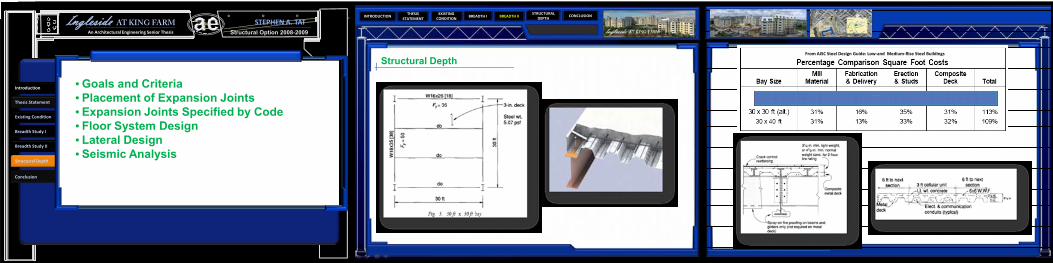
Structural DepthFrom AISC Steel Design Guide: Low‐and Medium‐Rise Steel Buildings
Structural Option 2008-2009Ingleside AT KING FARM
An Architectural Engineering Senior Thesis
STEPHEN A. TAT
Structural Depth
Introduction
Thesis Statement
Existing Condition
Breadth Study I
Breadth Study II
Conclusion
• Goals and Criteria• Placement of Expansion Joints• Expansion Joints Specified by Code• Floor System Design• Lateral Design• Seismic Analysis
INTRODUCTIONTHESIS
STATEMENTBREADTH I BREADTH II CONCLUSION
STRUCTURAL DEPTH
EXISTING CONDITION
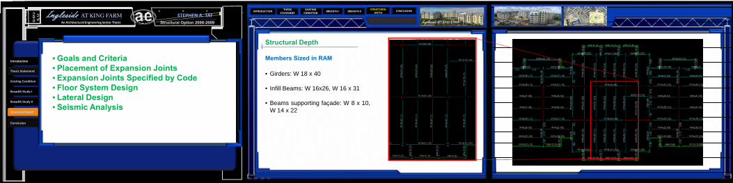
Structural Depth
Members Sized in RAM
• Girders: W 18 x 40
• Infill Beams: W 16x26, W 16 x 31
• Beams supporting façade: W 8 x 10,W 14 x 22
Structural Option 2008-2009Ingleside AT KING FARM
An Architectural Engineering Senior Thesis
STEPHEN A. TAT
Structural Depth
Introduction
Thesis Statement
Existing Condition
Breadth Study I
Breadth Study II
Conclusion
• Goals and Criteria• Placement of Expansion Joints• Expansion Joints Specified by Code• Floor System Design• Lateral Design• Seismic Analysis
INTRODUCTIONTHESIS
STATEMENTBREADTH I BREADTH II CONCLUSION
STRUCTURAL DEPTH
EXISTING CONDITION
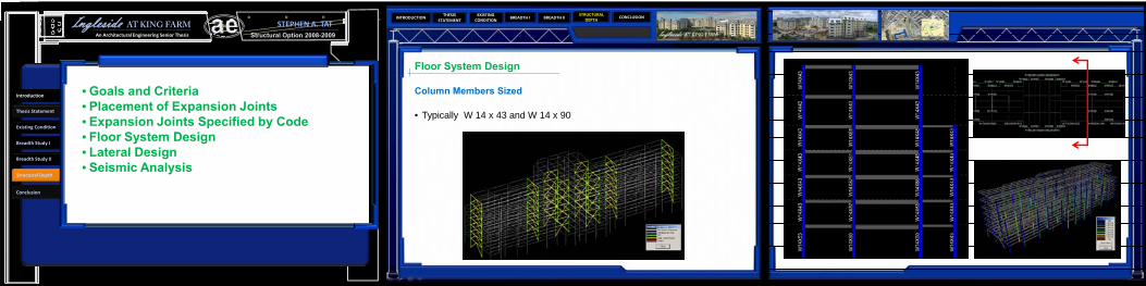
Floor System Design
Column Members Sized
• Typically W 14 x 43 and W 14 x 90
Structural Option 2008-2009Ingleside AT KING FARM
An Architectural Engineering Senior Thesis
STEPHEN A. TAT
Structural Depth
Introduction
Thesis Statement
Existing Condition
Breadth Study I
Breadth Study II
Conclusion
• Goals and Criteria• Placement of Expansion Joints• Expansion Joints Specified by Code• Floor System Design• Lateral Design• Seismic Analysis

INTRODUCTIONTHESIS
STATEMENTBREADTH I BREADTH II CONCLUSION
STRUCTURAL DEPTH
EXISTING CONDITION
• Lateral Design
Seismic Parameter
Used in EquivalentLateral Force Procedure
Criteria Value Code ReferenceOccupancy Category I Table 1.1Importance Factor 1 Table 11.5‐1
Spectral Acceleration for Short Periods (Ss)
1.656 www.usgs.org
Spectral Acceleration for 1 Second Periods (S1)
0.59 www.usgs.org
Site Coefficient, Fa 1 ASCE 7‐05 Table 11.4‐1
Site Coefficient, Fv 1.5 ASCE 7‐05 Table 11.4‐2Site Class D Assumed
Seismic Design Category D ASCE 7‐05 Section 11.6
R Factor (SCBF) 6ASCE 7‐05 Table 12.2‐1 #
B3SMS 1.66 ASCE 7‐05 Equation 11.4‐1
SM1 0.89 ASCE 7‐05 Equation 11.4‐2
SDS 1.104 ASCE 7‐05 Equation 11.4‐3
SD1 0.393 ASCE 7‐05 Equation 11.4‐3
Deflection Amplification Cd 5ASCE 7‐05 Table 12.2‐1 #
B3
Over strength Factor Ω0g 2
ASCE 7‐05 Table 12.2‐1 # B3
Criteria ValueCode
Referencex 0.75 Table 12.8.2Ct 0.02 Table 12.8.2
hu 94
Ta=Cthux 0.6038Cu 1.4 Table 12.8.1
T=Ta*Cu 0.845286478TL 8
(T>TL) CS 0.733370513W 7585.80k 2
Vertical Force Distribution N-S DirectionFloor Height (Ft.) Weight (Kips) Cvx Fx (kips) Story Shear
Roof 12.00 915.40 0.13 76.69 76.697 12.00 930.90 0.13 77.99 154.686 10.00 1142.80 0.14 79.78 234.465 10.00 1143.50 0.14 79.83 314.294 10.00 1144.30 0.14 79.89 394.183 10.00 1147.10 0.14 80.08 474.262 14.00 1161.80 0.19 113.55 587.81
Total Weight 7585.8 kips
Seismic Base Shear 587.81 kipsOverturning Moment 6641.69 kip-ft
Vertical Force Distribution E-W Directionfloor Height (Ft.) Weight (Kips) Cvx Fx (kips) Story Shear
Roof 12.00 915.40 0.13 90.05 90.057 12.00 930.90 0.13 91.57 181.626 10.00 1142.80 0.14 93.68 275.295 10.00 1143.50 0.14 93.74 369.034 10.00 1144.30 0.14 93.80 462.833 10.00 1147.10 0.14 94.03 556.862 14.00 1161.80 0.19 133.33 690.19
Total Weight 7585.8 kips
Seismic Base Shear 690.19 kipsOverturning Moment 7798.48 kip-ft
Structural Option 2008-2009Ingleside AT KING FARM
An Architectural Engineering Senior Thesis
STEPHEN A. TAT
Structural Depth
Introduction
Thesis Statement
Existing Condition
Breadth Study I
Breadth Study II
Conclusion
• Goals and Criteria• Placement of Expansion Joints• Expansion Joints Specified by Code• Floor System Design• Lateral Design• Seismic Analysis

INTRODUCTIONTHESIS
STATEMENTBREADTH I BREADTH II CONCLUSION
STRUCTURAL DEPTH
EXISTING CONDITION
Structural Depth
Check for Irregularities Criteria
Horizontal Structural Irregularities (Table 12.3.1 ASCE)
Type Irregularity Varification Status
1a Torsional Checked with RAM Model ok
2 Reentrant CornerAll over the building ‐concentration forces at
cornersNG
3Diaphragm Discontinuity
None by inspecting drawings ok
4 Out of Plane Offsets None by inspecting drawings ok
5 Non Parallel SystemAll lateral resisting systems are parallel to major axis
ok
Vertical Structural Irregularities (Table 12.3.2 ASCE)Type Irregularity Varification Status
1a Stiffness‐Soft StoryLevel 6 is a soft story due
to varying heightsNG
2 Weight (Mass)calculated weight of each
story and is fineok
3 Vertical Geometric (66/51)=1.29 < 1.3 ok
4
In‐Plane Discontinuity of Vertical Lateral Force Resisting
Elements
No by drawing speculations
ok
5a, 5Discontinuity on Lateral Strength
Lateral system runs continuously
ok
Structural Option 2008-2009Ingleside AT KING FARM
An Architectural Engineering Senior Thesis
STEPHEN A. TAT
Structural Depth
Introduction
Thesis Statement
Existing Condition
Breadth Study I
Breadth Study II
Conclusion
• Goals and Criteria• Placement of Expansion Joints• Expansion Joints Specified by Code• Floor System Design• Lateral Design• Seismic Analysis
INTRODUCTIONTHESIS
STATEMENTBREADTH I BREADTH II CONCLUSION
STRUCTURAL DEPTH
EXISTING CONDITION
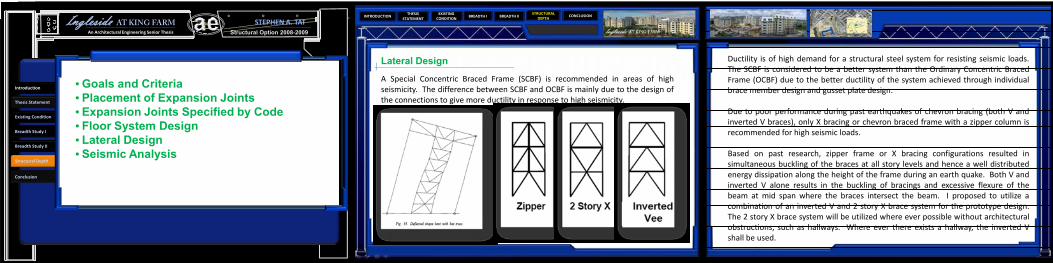
Lateral Design Ductility is of high demand for a structural steel system for resisting seismic loads.The SCBF is considered to be a better system than the Ordinary Concentric BracedFrame (OCBF) due to the better ductility of the system achieved through individualbrace member design and gusset plate design.
Due to poor performance during past earthquakes of chevron bracing (both V andinverted V braces), only X bracing or chevron braced frame with a zipper column isrecommended for high seismic loads.
Based on past research, zipper frame or X bracing configurations resulted insimultaneous buckling of the braces at all story levels and hence a well distributedenergy dissipation along the height of the frame during an earth quake. Both V andinverted V alone results in the buckling of bracings and excessive flexure of thebeam at mid span where the braces intersect the beam. I proposed to utilize acombination of an inverted V and 2 story X brace system for the prototype design.The 2 story X brace system will be utilized where ever possible without architecturalobstructions, such as hallways. Where ever there exists a hallway, the inverted Vshall be used.
A Special Concentric Braced Frame (SCBF) is recommended in areas of highseismicity. The difference between SCBF and OCBF is mainly due to the design ofthe connections to give more ductility in response to high seismicity.
Structural Option 2008-2009Ingleside AT KING FARM
An Architectural Engineering Senior Thesis
STEPHEN A. TAT
Structural Depth
Introduction
Thesis Statement
Existing Condition
Breadth Study I
Breadth Study II
Conclusion
• Goals and Criteria• Placement of Expansion Joints• Expansion Joints Specified by Code• Floor System Design• Lateral Design• Seismic Analysis
INTRODUCTIONTHESIS
STATEMENTBREADTH I BREADTH II CONCLUSION
STRUCTURAL DEPTH
EXISTING CONDITION
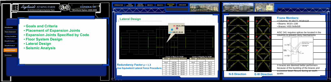
Lateral Design
N-S Direction E-W Direction
Redundancy Factor ρ = 1.3Use Equivalent Lateral Force Procedure.
CR: 141.8, 2954
CM: 140.27, 29.18
Frame Members:• Columns: W 16x77, W18x119• Beams: W18 x 106• Braces: HSS 9x9x5/8
AISC 341 requires splices be located in the columns to prevent story mechanisms
X-braces are deemed better performers because of the buckling of the braces and excessive beam flexure during an earth quake.
Center of Rigidity for SCBFStory X Direction Y Direction
Roof 142.67 29.737 142.67 29.736 141.8 29.55 141.8 29.54 141.8 29.53 141.8 29.52 141.8 29.5
Center of Mass for SCBFStory X Direction Y Direction
Roof 140.05 23.197 140.05 23.196 140.78 29.185 140.78 29.184 140.78 29.183 140.78 29.182 140.78 29.18
Structural Option 2008-2009Ingleside AT KING FARM
An Architectural Engineering Senior Thesis
STEPHEN A. TAT
Structural Depth
Introduction
Thesis Statement
Existing Condition
Breadth Study I
Breadth Study II
Conclusion
• Goals and Criteria• Placement of Expansion Joints• Expansion Joints Specified by Code• Floor System Design• Lateral Design• Seismic Analysis

INTRODUCTIONTHESIS
STATEMENTBREADTH I BREADTH II CONCLUSION
STRUCTURAL DEPTH
EXISTING CONDITION
Lateral DesignAfter the earthquake of Northridge 1994, it was discovered that steel momentframe buildings experience brittle fractures of beam‐to‐column connections. It haddemonstrated that brittle fractures was initiated within connections at very lowlevels of plastic demand and also while the structures remained elastic.
Due to this event, FEMA 350 prequalified several connection types. One is thewelded flange plate (WFP), the other being a reduced beam section (RBS).
The RBS connection utilizes less material, and thus is the preferred choice in theprototype design of Ingleside at King Farm. RBS also has no reinforcing other thanthe weld metal is used to joint the flanges of the beam to the column. This is so thatplastic hinges will form at these reduced section areas of the beam. The formationof plastic hinges at the beam‐column interface during seismic event results in largeinelastic strain demands at the connection leading to brittle failure. The reducedsection of the beam at the desired location of the plastic hinge can remedy thisissue.
Structural Option 2008-2009Ingleside AT KING FARM
An Architectural Engineering Senior Thesis
STEPHEN A. TAT
Structural Depth
Introduction
Thesis Statement
Existing Condition
Breadth Study I
Breadth Study II
Conclusion
• Goals and Criteria• Placement of Expansion Joints• Expansion Joints Specified by Code• Floor System Design• Lateral Design• Seismic Analysis

INTRODUCTIONTHESIS
STATEMENTBREADTH I BREADTH II CONCLUSION
STRUCTURAL DEPTH
EXISTING CONDITION
Seismic Analysis
Drift and Displacement Calculations for SCBF N-S Direction
Story Height (Ft.)
Story Displacement (in)
δxe (in) δx (in) Δa (in) Final
Results
Roof 12 0.684 0.104 0.475 2.880 ok7 12 0.580 0.117 0.534 2.880 ok6 10 0.463 0.101 0.461 2.400 ok5 10 0.362 0.101 0.461 2.400 ok4 10 0.261 0.096 0.438 2.400 ok3 10 0.165 0.084 0.384 2.400 ok2 14 0.081 0.081 0.370 3.360 ok
Soft Story Check for SCBF N‐S Direction
Story Drift Drift Ratio0.7x the
Story Drift Ratio
0.8x the Story Drift
Ratio
Avg. Story Drift Ratio of Next 3
Stories
Soft Story Issue
0.104 0.0087 0.0061 0.0069 ‐ No0.117 0.0097 0.0068 0.0078 ‐ No0.101 0.0101 0.0071 0.0081 ‐ No0.101 0.0101 0.0071 0.0081 0.0095 No0.096 0.0096 0.0067 0.0077 0.0100 No0.084 0.0084 0.0059 0.0067 0.0099 No0.081 0.0058 0.0041 0.0046 0.0094 No
Structural Option 2008-2009Ingleside AT KING FARM
An Architectural Engineering Senior Thesis
STEPHEN A. TAT
Structural Depth
Introduction
Thesis Statement
Existing Condition
Breadth Study I
Breadth Study II
Conclusion
• Goals and Criteria• Placement of Expansion Joints• Expansion Joints Specified by Code• Floor System Design• Lateral Design• Seismic Analysis

INTRODUCTIONTHESIS
STATEMENTBREADTH I BREADTH II CONCLUSION
STRUCTURAL DEPTH
EXISTING CONDITION
Seismic Analysis
Drift and Displacement Calculations for SCBF E‐W Direction
Story Height (Ft.)
Story Displacement (in)
δxe (in) δx (in) Δa (in)Final Results
Roof 12 1.055 0.206 0.988 2.880 ok
7 12 0.849 0.176 0.844 2.880 ok
6 10 0.673 0.198 0.950 2.400 ok
5 10 0.475 0.164 0.784 2.400 ok
4 10 0.312 0.162 0.775 2.400 ok
3 10 0.150 0.150 0.719 2.400 ok
2 14 0.000 0.000 0.000 3.360 ok
Soft Story Check for SCBF E‐W Direction
Story Drift Drift Ratio0.7x the Story Drift
Ratio
0.8x the Story Drift
Ratio
Avg. Story Drift Ratio of Next 3
Stories
Soft Story Issue
0.206 0.0172 0.0120 0.0137 ‐ No0.176 0.0147 0.0103 0.0117 ‐ No0.198 0.0198 0.0139 0.0158 0.0106 Yes0.164 0.0164 0.0114 0.0131 0.0172 No0.162 0.0162 0.0113 0.0129 0.0169 No0.150 0.0150 0.0105 0.0120 0.0174 No0.000 0.0000 0.0000 0.0000 0.0158 No
Other Checks: Inherent Torsion, Amplification Factor Ao, Accidental Torsion
Structural Option 2008-2009Ingleside AT KING FARM
An Architectural Engineering Senior Thesis
STEPHEN A. TAT
Structural Depth
Introduction
Thesis Statement
Existing Condition
Breadth Study I
Breadth Study II
Conclusion
• Goals and Criteria• Placement of Expansion Joints• Expansion Joints Specified by Code• Floor System Design• Lateral Design• Seismic Analysis
INTRODUCTIONTHESIS
STATEMENTBREADTH I BREADTH II CONCLUSION
STRUCTURAL DEPTH
EXISTING CONDITION
Structural Option 2008-2009Ingleside AT KING FARM
An Architectural Engineering Senior Thesis
STEPHEN A. TAT
Structural Depth
Introduction
Thesis Statement
Existing Condition
Breadth Study I
Breadth Study II
Conclusion
• Goals and Criteria• Placement of Expansion Joints• Expansion Joints Specified by Code• Floor System Design• Lateral Design• Seismic Analysis

INTRODUCTIONTHESIS
STATEMENTBREADTH I BREADTH II CONCLUSION
STRUCTURAL DEPTH
EXISTING CONDITION
Width of Seismic AnalysisDrift and Displacement Calculations for SCBF E‐W
Direction For section 2Story Story Displacement (in) ΔM (in)Roof 1.270 6.357 1.090 5.456 0.779 3.8955 0.615 3.0754 0.459 2.2953 0.306 1.532 0.167 0.835
Drift and Displacement Calculations for SCBF E‐W Direction For Section 1Story Story Displacement (in)Roof 1.0557 0.8496 0.6735 0.4754 0.3123 0.1502 0.000
Comparing the story displacements of Building Section 1 and 2, Building Section 2express a greater displacement of 1.27 inches at the roof level. This results in ΔM =6.35. Since this value only accounts for section 2, this value must be multiplied by2 giving ΔMoverall = 12.7 inches.
It was concluded that a seismic expansion joint of 2 feet is required for theseparation of the two building sections.
Structural Option 2008-2009Ingleside AT KING FARM
An Architectural Engineering Senior Thesis
STEPHEN A. TAT
Structural Depth
Introduction
Thesis Statement
Existing Condition
Breadth Study I
Breadth Study II
Conclusion
• Goals and Criteria• Placement of Expansion Joints• Expansion Joints Specified by Code• Floor System Design• Lateral Design• Seismic Analysis
INTRODUCTIONTHESIS
STATEMENTBREADTH I BREADTH II CONCLUSION
STRUCTURAL DEPTH
EXISTING CONDITION
Structural Systems Comparison
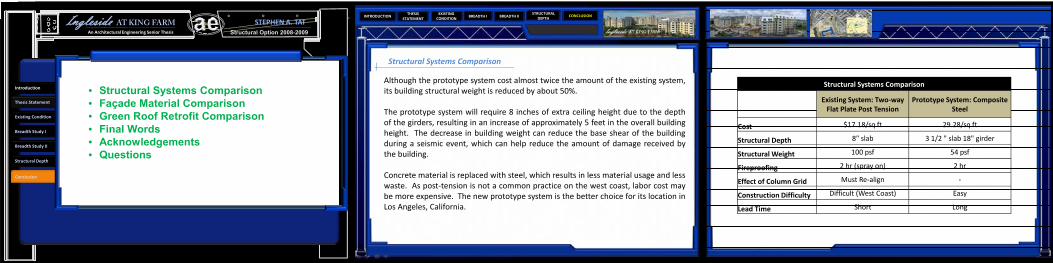
Although the prototype system cost almost twice the amount of the existing system,its building structural weight is reduced by about 50%.
The prototype system will require 8 inches of extra ceiling height due to the depthof the girders, resulting in an increase of approximately 5 feet in the overall buildingheight. The decrease in building weight can reduce the base shear of the buildingduring a seismic event, which can help reduce the amount of damage received bythe building.
Concrete material is replaced with steel, which results in less material usage and lesswaste. As post‐tension is not a common practice on the west coast, labor cost maybe more expensive. The new prototype system is the better choice for its location inLos Angeles, California.
Structural Systems Comparison
Existing System: Two‐way Flat Plate Post Tension
Prototype System: Composite Steel
Cost $17.18/sq ft 29.28/sq ft
Structural Depth 8" slab 3 1/2 " slab 18" girder
Structural Weight 100 psf 54 psf
Fireproofing 2 hr (spray on) 2 hr
Effect of Column Grid Must Re‐align ‐
Construction Difficulty Difficult (West Coast) Easy
Lead Time Short Long
Structural Option 2008-2009Ingleside AT KING FARM
An Architectural Engineering Senior Thesis
STEPHEN A. TAT
Structural Depth
Introduction
Thesis Statement
Existing Condition
Breadth Study I
Breadth Study II
Conclusion
• Structural Systems Comparison• Façade Material Comparison• Green Roof Retrofit Comparison• Final Words• Acknowledgements• Questions
INTRODUCTIONTHESIS
STATEMENTBREADTH I BREADTH II CONCLUSION
STRUCTURAL DEPTH
EXISTING CONDITION
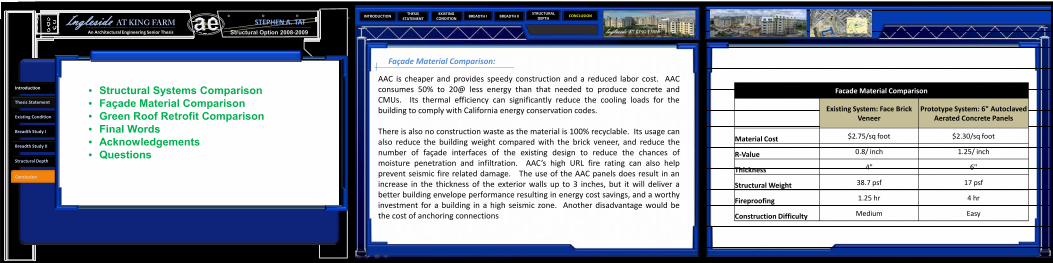
Façade Material Comparison:
AAC is cheaper and provides speedy construction and a reduced labor cost. AACconsumes 50% to 20@ less energy than that needed to produce concrete andCMUs. Its thermal efficiency can significantly reduce the cooling loads for thebuilding to comply with California energy conservation codes.
There is also no construction waste as the material is 100% recyclable. Its usage canalso reduce the building weight compared with the brick veneer, and reduce thenumber of façade interfaces of the existing design to reduce the chances ofmoisture penetration and infiltration. AAC’s high URL fire rating can also helpprevent seismic fire related damage. The use of the AAC panels does result in anincrease in the thickness of the exterior walls up to 3 inches, but it will deliver abetter building envelope performance resulting in energy cost savings, and a worthyinvestment for a building in a high seismic zone. Another disadvantage would bethe cost of anchoring connections
Facade Material Comparison
Existing System: Face Brick Veneer
Prototype System: 6" Autoclaved Aerated Concrete Panels
Material Cost $2.75/sq foot $2.30/sq foot
R‐Value 0.8/ inch 1.25/ inch
Thickness 4" 6"
Structural Weight 38.7 psf 17 psf
Fireproofing 1.25 hr 4 hr
Construction Difficulty Medium Easy
Structural Option 2008-2009Ingleside AT KING FARM
An Architectural Engineering Senior Thesis
STEPHEN A. TAT
Structural Depth
Introduction
Thesis Statement
Existing Condition
Breadth Study I
Breadth Study II
Conclusion
• Structural Systems Comparison• Façade Material Comparison• Green Roof Retrofit Comparison• Final Words• Acknowledgements• Questions

INTRODUCTIONTHESIS
STATEMENTBREADTH I BREADTH II CONCLUSION
STRUCTURAL DEPTH
EXISTING CONDITION
Green Roof Retrofit Comparison:
The usage of an extensive green roof can contribute to the reduction of cooling loadsand thus energy consumption and cost by the building. In a life cycle cost analysis, itcan increase the service life of the roof membrane, and can help increase therevenue of the residential building.
Environmental improvements includes improved water and air quality, which is anemerging issue in Los Angeles due to traffic and air pollutions. It can also reducereflection and transmission of heat and glare to surrounding buildings, and mitigateurban heat‐island effects. It can be used to control storm water runoff and improvethe aesthetic environment. Although the initial cost at first may be expensive, it willpay off in a least two years mainly from revenues and the reduction of mechanicalloads. With such a vast roof surface area, Ingleside and King Farm can significantlybenefit from the implementing a green roof system. Its extra dead load bears noburden to the structural system as demonstrated in the design calculations.
Roof Retrofit Comparison
Existing System: PVC Single Ply System
Prototype System: Green Roof Retrofit
Cost $ 3.75/sq ft 15$/sq ft
R‐Value 10.75 23.4
Structural Weight 40 psf 50 psf
Reflectivity 95% ‐
Emittance 80% ‐
Solar Reflectance index 110 ‐
Average Survice Life 9.5 50
Maintenance Medium to High Low
Structural Option 2008-2009Ingleside AT KING FARM
An Architectural Engineering Senior Thesis
STEPHEN A. TAT
Structural Depth
Introduction
Thesis Statement
Existing Condition
Breadth Study I
Breadth Study II
Conclusion
• Structural Systems Comparison• Façade Material Comparison• Green Roof Retrofit Comparison• Final Words• Acknowledgements• Questions

INTRODUCTIONTHESIS
STATEMENTBREADTH I BREADTH II CONCLUSION
STRUCTURAL DEPTH
EXISTING CONDITION
Final Works:
Better performance always comes with a cost, however there are paybacksthat out weights the dollar amount.
In the case of retrofitting a building for seismic resistance, the reward couldbe the reduction in lives lost, medical costs, loss of tenants, loss of assetswithin the building, and loss of building functions.
Other benefits include reduction in insurance premiums, increase in propertyvalue, and higher income from tenants.
Redesigning a prototype design of Ingleside at King Farm for Los Angeles,California will be costly due to the special requirements by codes to makethe building safer during and right after a seismic event.
Indirect damage includes fires caused by seismic activity, which can weakenthe structural system and cause structural failures. In the case of extremelyhigh seismic activity, such as the Northridge Earthquake in 1994 due to acombination of direct shear and poor soil conditions, retrofitting the buildingdesign and to resist seismicity can result in significant savings due todecrease in damages and delayed building functions, and more importantly,increasing the safety and survival rate of the occupants.
Structural Option 2008-2009Ingleside AT KING FARM
An Architectural Engineering Senior Thesis
STEPHEN A. TAT
Structural Depth
Introduction
Thesis Statement
Existing Condition
Breadth Study I
Breadth Study II
Conclusion
• Structural Systems Comparison• Façade Material Comparison• Green Roof Retrofit Comparison• Final Words• Acknowledgements• Questions
INTRODUCTIONTHESIS
STATEMENTBREADTH I BREADTH II CONCLUSION
STRUCTURAL DEPTH
EXISTING CONDITION
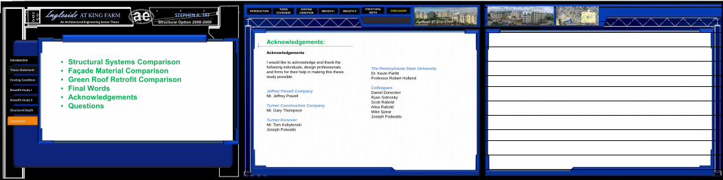
Acknowledgements:Acknowledgements
I would like to acknowledge and thank the following individuals, design professionals, and firms for their help in making this thesis study possible.
Jeffrey Powell CompanyMr. Jeffrey Powell
Turner Construction CompanyMr. Gary Thompson
Turner-KonoverMr. Tom KobylenskiJoseph Potwatts
The Pennsylvania State UniversityDr. Kevin ParfittProfessor Robert Holland
ColleaguesDaniel DoneckerRyan SolnoskyScott RaboldAlisa RaboldMike SpearJoseph Podwatts
Structural Option 2008-2009Ingleside AT KING FARM
An Architectural Engineering Senior Thesis
STEPHEN A. TAT
Structural Depth
Introduction
Thesis Statement
Existing Condition
Breadth Study I
Breadth Study II
Conclusion
• Structural Systems Comparison• Façade Material Comparison• Green Roof Retrofit Comparison• Final Words• Acknowledgements• Questions

INTRODUCTIONTHESIS
STATEMENTBREADTH I BREADTH II CONCLUSION
STRUCTURAL DEPTH
EXISTING CONDITION
Thank you…
Questions?
Structural Option 2008-2009Ingleside AT KING FARM
An Architectural Engineering Senior Thesis
STEPHEN A. TAT
Structural Depth
Introduction
Thesis Statement
Existing Condition
Breadth Study I
Breadth Study II
Conclusion
• Structural Systems Comparison• Façade Material Comparison• Green Roof Retrofit Comparison• Final Words• Acknowledgements• Questions