initial conditions & boundary conditions used in the rsm · pdf filersm training hesm...
TRANSCRIPT

RSM Training HESM Instructional Materials for Training Purposes Only Module 9: Initial Conditions & Boundary Conditions used in the RSM
Hydrologic and Environmental Systems Modeling Page 9.1
Lecture 9: Initial Conditions & Boundary Conditions used in the RSM—Types and data sources
Model performance is largely a function of the Initial Conditions (ICs) and Boundary Conditions
(BCs) applied to the Regional Simulation Model (RSM). The quality and distribution of these data
determine the effectiveness of the RSM subregional implementations. This lecture covers types of
boundary conditions and available data.
Initial Conditions & Boundary Conditions used in the RSM Initial Conditions & Boundary Conditions used in the RSM
Types and data sourcesTypes and data sources
- Initial conditions- Boundary conditions- Data sources

RSM Training HESM Instructional Materials for Training Purposes Only Module 9: Initial Conditions & Boundary Conditions used in the RSM
Page 9.2 Hydrologic and Environmental Systems Modeling
2
Initial Conditions and Boundary ConditionsInitial Conditions and Boundary Conditions
Initial conditions• Critical start-up
• Spatially variable data
• Constants
Boundary conditions• Spatially variable data
Rainfall and reference ET
• Verified data sources
MOD1 time series data sets
SFWMM data sets
• Rule curves
Initial conditions• Critical start-up
• Spatially variable data
• Constants
Boundary conditions• Spatially variable data
Rainfall and reference ET
• Verified data sources
MOD1 time series data sets
SFWMM data sets
• Rule curves
The Initial Conditions for the mesh cells
can be set as:
Constant,
Indexed Through a GMS input file
The Initial Conditions for the network and
wcdwaterbodies can be set as:
Constant Through an indeed entry file
The indexed method allows for the input of
zonal values. Input for other waterbodies is
as a single‐valued constant.
Initial Conditions
The choice of Initial Conditions determines
how long it will take the model to come to
the correct transient condition. For the
regional system it is appropriate to start the
system wetter than necessary, as the system
drains more efficiently than it supplies
water. For the surface hydrology (HPMs) it
is necessary to avoid inundation, as the
developed areas of the system cannot
effectively transpire from a flooded
condition.
Boundary Conditions
Typically, a model domain is defined by Boundary Conditions such as watershed boundaries that are
no‐flow conditions or the coastal tidal boundary that has a known head time series. The subregional
RSM implementations rely on a time series of observed historical stage data and simulated stage and
flow data from the South Florida Water Management Model (SFWMM). The boundary conditions for
impoundments, lakes and WCDs include rule curves that set the seasonal head.
There are three general types of available boundary conditions for waterbodies and watermovers:
specified head (Dirichelt), general head (mixed) and flow (Neumann) conditions. Specified head or
general head boundary conditions are used for the downstream boundary conditions for mesh cells
and segments. Upstream boundary conditions are typically flow conditions.
3
Initial Conditions and Boundary ConditionsInitial Conditions and Boundary Conditions
Initial Conditions
• Wet
• Dry
Boundary Conditions
• No-flow
• Head
• Flow
• Tidal
Initial Conditions
• Wet
• Dry
Boundary Conditions
• No-flow
• Head
• Flow
• Tidal

RSM Training HESM Instructional Materials for Training Purposes Only Module 9: Initial Conditions & Boundary Conditions used in the RSM
Hydrologic and Environmental Systems Modeling Page 9.3
The allowable input for the Initial Conditions depends on the waterbody type.
For impoundments, lakes and basins, the initial head is entered as a single value for each instance.
For wcdwaterbodies and the network segments, the initial head is entered for all instances as an
indexed‐entry file.
These values allow for spatial variability in the input. The initial heads for the mesh cells can be
entered as indexed‐entries or as a standard Groundwater Modeling System (GMS)‐generated file.
4
Initial ConditionsInitial Conditions
Mesh
<shead> (indexed | const | gms | gmslayer)
network
<initial> (indexed)
Wcdwaterbodies
<initialcondfile> (indexed entry file)
Impoundments
<head> (single value)
Lakes
head0 (single value)
Basins
initial_head (single value)
Mesh
<shead> (indexed | const | gms | gmslayer)
network
<initial> (indexed)
Wcdwaterbodies
<initialcondfile> (indexed entry file)
Impoundments
<head> (single value)
Lakes
head0 (single value)
Basins
initial_head (single value)

RSM Training HESM Instructional Materials for Training Purposes Only Module 9: Initial Conditions & Boundary Conditions used in the RSM
Page 9.4 Hydrologic and Environmental Systems Modeling
Vertical Boundary Conditions for the model are defined by a rainfall and a reference vegetation
evapotranspiration record. Both of the data sets were developed from many field measurement
stations.
The time series data at each station were used to create an interpolated record of values for each cell
in the mesh. The Interpolation method requires a starting point for the grid which is defined using the
state‐plane coordinates in the southwest corner of the grid. This method requires a specification of the
timestep (minutes) and the depth (feet).
5
Vertical Boundary Conditions: Data sourcesVertical Boundary Conditions: Data sources
Rainfall
Reference Vegetation Evapotranspiration
Rainfall
Reference Vegetation Evapotranspiration

RSM Training HESM Instructional Materials for Training Purposes Only Module 9: Initial Conditions & Boundary Conditions used in the RSM
Hydrologic and Environmental Systems Modeling Page 9.5
It is necessary to establish boundary
conditions for each of the waterbodies
instantiated in the RSM. The default
boundary condition is noflow across the
boundary of the model domain.
There is a common set of choices for data
input options for each of the boundary
condition types. These include constant
values, rule curves and time series entered
as the DSS files.
Rule curves are repeating annual cycles that
are useful when the waterbody has a
preferred annual stage pattern (e.g., a stage
regulation schedule).
The DSS file is used for long‐term daily time
series.
6
Boundary Conditions for WaterbodiesBoundary Conditions for Waterbodies
Mesh
Network
Lakes
Basins
Wcdwaterbodies [noflow (ol)]
Impoundments
Mesh
Network
Lakes
Basins
Wcdwaterbodies [noflow (ol)]
Impoundments
7
Boundary Conditions: Input typesBoundary Conditions: Input types
Constant <const>
Data Storage System <dss>
Rulecurve <rc>
Constant <const>
Data Storage System <dss>
Rulecurve <rc>

RSM Training HESM Instructional Materials for Training Purposes Only Module 9: Initial Conditions & Boundary Conditions used in the RSM
Page 9.6 Hydrologic and Environmental Systems Modeling
There are several possible boundary conditions for a mesh. The noflow boundary condition is used
for catchment boundaries and along levees.
There are 3 boundaries available for walls:
Fixed head General head Uniform flow
In each case, the wall is specified by a list of nodes or a list of walls. It is also possible to assign
boundary conditions to the cell instead of a wall.
The well boundary condition is useful for applying a flow to the cell or extracting water from a cell.
The <bermseepage> is an internal boundary condition that is used to move water across a berm.
8
<mesh_bc><mesh_bc>
noflow section (ol,ol-gw,gw) [walllist|nodelist|
wallhead section [uniform|wts2pt|endpts|nodelist|wallist]
wallghb section [uniform|wts2pt|endpts|nodelist|wallist]
walluf [walllist|nodelist|
cellhead
cellghb
well
bermseepage
• Inputs: [const|dss|rc|tsin]
noflow section (ol,ol-gw,gw) [walllist|nodelist|
wallhead section [uniform|wts2pt|endpts|nodelist|wallist]
wallghb section [uniform|wts2pt|endpts|nodelist|wallist]
walluf [walllist|nodelist|
cellhead
cellghb
well
bermseepage
• Inputs: [const|dss|rc|tsin]

RSM Training HESM Instructional Materials for Training Purposes Only Module 9: Initial Conditions & Boundary Conditions used in the RSM
Hydrologic and Environmental Systems Modeling Page 9.7
This slide shows the syntax for implementing the Mesh Boundary Conditions. The noflow can be
applied to:
Overland flow “ol” Groundwater flow “gw” Both “ol_gw”
Note: “ol‐gw” is a syntax error and does nothing.
The wall general head boundary applies a fixed external head on a wall conductivity, which must be
less than 1.0. The <wallhead> element is a preferred boundary condition which is more stable than the
<wallghb> element.
Each of these boundary conditions can be assigned a label which is used for tracking the flows in the
output water budget. The application of a rulecurve as a head condition, which may represent a
regulatory stage schedule or an annual cycle, is a typical example.
9
Mesh Boundary ConditionsMesh Boundary Conditions

RSM Training HESM Instructional Materials for Training Purposes Only Module 9: Initial Conditions & Boundary Conditions used in the RSM
Page 9.8 Hydrologic and Environmental Systems Modeling
The syntax of the Cell Boundary Conditions is similar to the Wall Boundary Conditions, except they
apply to the head of the cell. Although Cell Boundary Conditions are more stable than Wall Boundary
Conditions, and produce faster run times, they fix the head in the cell which may be a problem with
large cells. As such, it is desirable to create a row of cells outside the Catchment boundary on which
to apply the Cell Boundary Conditions.
The Well Boundary Condition has a watermover ID label so that the flows can be readily tracked.
The Wall Uniform Flow Boundary Condition is used to apply a small flow across a basin boundary.
10
Mesh Boundary ConditionsMesh Boundary Conditions
RSM Training HESM Instructional Materials for Training Purposes Only Module 9: Initial Conditions & Boundary Conditions used in the RSM
Hydrologic and Environmental Systems Modeling Page 9.9
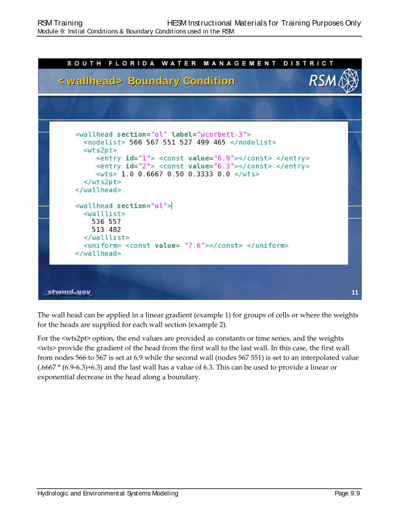
The wall head can be applied in a linear gradient (example 1) for groups of cells or where the weights
for the heads are supplied for each wall section (example 2).
For the <wts2pt> option, the end values are provided as constants or time series, and the weights
<wts> provide the gradient of the head from the first wall to the last wall. In this case, the first wall
from nodes 566 to 567 is set at 6.9 while the second wall (nodes 567 551) is set to an interpolated value
(.6667 * (6.9‐6.3)+6.3) and the last wall has a value of 6.3. This can be used to provide a linear or
exponential decrease in the head along a boundary.
11
<wallhead> Boundary Condition<wallhead> Boundary Condition
RSM Training HESM Instructional Materials for Training Purposes Only Module 9: Initial Conditions & Boundary Conditions used in the RSM
Page 9.10 Hydrologic and Environmental Systems Modeling
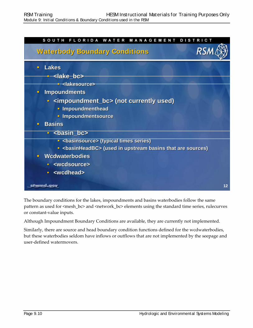
The boundary conditions for the lakes, impoundments and basins waterbodies follow the same
pattern as used for <mesh_bc> and <network_bc> elements using the standard time series, rulecurves
or constant‐value inputs.
Although Impoundment Boundary Conditions are available, they are currently not implemented.
Similarly, there are source and head boundary condition functions defined for the wcdwaterbodies,
but these waterbodies seldom have inflows or outflows that are not implemented by the seepage and
user‐defined watermovers.
12
Waterbody Boundary ConditionsWaterbody Boundary Conditions
Lakes
• <lake_bc> <lakesource>
Impoundments
• <impoundment_bc> (not currently used) Impoundmenthead
Impoundmentsource
Basins
• <basin_bc> <basinsource> (typical times series)
<basinHeadBC> (used in upstream basins that are sources)
Wcdwaterbodies
• <wcdsource>
• <wcdhead>
Lakes
• <lake_bc> <lakesource>
Impoundments
• <impoundment_bc> (not currently used) Impoundmenthead
Impoundmentsource
Basins
• <basin_bc> <basinsource> (typical times series)
<basinHeadBC> (used in upstream basins that are sources)
Wcdwaterbodies
• <wcdsource>
• <wcdhead>

RSM Training HESM Instructional Materials for Training Purposes Only Module 9: Initial Conditions & Boundary Conditions used in the RSM
Hydrologic and Environmental Systems Modeling Page 9.11
There are several boundary conditions for network segments that are similar to the mesh boundary
conditions. These include the:
<segmenthead> element which sets the head for the segment <junctionhead> element which sets the head at a junction between two segments <segmentghb> element which sets the head and conductivity of the segment boundary <segmentsource> element which is used to set the flow into a boundary
Each of these boundary conditions can have a constant input, time series or rule curve input.
The <uniformflow> element is used to apply flow between two segments based on slope.
The junction block breaks the continuity between two segments to allow flow to be determined by a
user‐specified watermover (structure).
13
<network_bc><network_bc>
Common boundary conditions
• segmentsource
• segmenthead
• junctionhead
• segmentghb
Inputs: [dss | const | rc ]
uniformflow Uniform inflow/outflow based on slope
junctionblock Used to create a block for structure location
Common boundary conditions
• segmentsource
• segmenthead
• junctionhead
• segmentghb
Inputs: [dss | const | rc ]
uniformflow Uniform inflow/outflow based on slope
junctionblock Used to create a block for structure location

RSM Training HESM Instructional Materials for Training Purposes Only Module 9: Initial Conditions & Boundary Conditions used in the RSM
Page 9.12 Hydrologic and Environmental Systems Modeling
The syntax for the Segment boundary conditions is similar to the specification of the boundary
conditions for the walls and the cells.
The typical <segmenthead> will be a constant value or a time series such as a tidal head at the coast. The <segmentsource> will typically be a historical flow record or simulated flow from the SFWMM. The <segmentsource> can be used as an internal boundary condition during calibration.
14
Network Boundary ConditionsNetwork Boundary Conditions

RSM Training HESM Instructional Materials for Training Purposes Only Module 9: Initial Conditions & Boundary Conditions used in the RSM
Hydrologic and Environmental Systems Modeling Page 9.13
The <setflow> watermover behaves like an internal boundary condition. It moves water from one
waterbody to another waterbody based on constant flow or a time series. It is typically used when it is
desirable to fix the flow at a structure for the values of the historically observed flow or calculated
flow from the SFWMM. It can also be used to set the flow at a structure to zero.
15
Watermover Boundary ConditionsWatermover Boundary Conditions
Setflow Setflow

RSM Training HESM Instructional Materials for Training Purposes Only Module 9: Initial Conditions & Boundary Conditions used in the RSM
Page 9.14 Hydrologic and Environmental Systems Modeling
A primary use of RSM implementations is to
simulate the hydrology of south Florida for
evaluating the long‐term regional impact of
alternative formulations of water resource
management strategies. These simulations
are conducted using the historical (1965–
2005) datasets for boundary conditions:
Rainfall RefET, Stage Flows
This type of modeling also requires long‐
term historical observations against which
to compare model simulations.
There are three different time series datasets available for creating boundary conditions. There are
many sites in south Florida at which stage and flow data have been collected for many years. These
data have been used to create two groups of hydrologic time series data; ‘MOD1’ and ‘MOD2’. The
final dataset includes the simulation results from the SFWMM that are frequently used for boundary
conditions.
The field data were processed to produce
two groups of time series.
The field data are often incomplete and have
erroneous data (from faulty benchmarks or
recorders).
The South Florida Water Management
District (SFWMD) conducted an intensive
review of the raw data and modified the
daily time series using rigorous methods
and has stored these data as ‘MOD1’ data in
the SFWMD DBHydro hydrologic database.
These data have no gaps in the time series.
And, outliers, as well as erroneous data, have been corrected.
A second, less accurate, group of time series data (MOD2) are available for locations where little data
are available.
16
Boundary Conditions: Times Series DatasetsBoundary Conditions: Times Series Datasets
Verified observed stage and flow time series
• Long-term SFWMD, USGS and other agency datasets
• MOD1 data (498 stage, 120 flow stations)
• MOD2 data (25 stations)
South Florida Water Management Model simulations
• SFWMMv5.4 simulations (26 flows, 95 stage)
Verified observed stage and flow time series
• Long-term SFWMD, USGS and other agency datasets
• MOD1 data (498 stage, 120 flow stations)
• MOD2 data (25 stations)
South Florida Water Management Model simulations
• SFWMMv5.4 simulations (26 flows, 95 stage)
17
SFWMD Flows & StagesSFWMD Flows & Stages
Stage_CV_v1.dss
• Mod1, Mod2 and simulated data
Mod1: Scrubbed flow and stage data
• Outliers
• Repaired gaps
• Continuous long-term data
Mod2:
• Less continuous than Mod1 data
Stage_CV_v1.dss
• Mod1, Mod2 and simulated data
Mod1: Scrubbed flow and stage data
• Outliers
• Repaired gaps
• Continuous long-term data
Mod2:
• Less continuous than Mod1 data

RSM Training HESM Instructional Materials for Training Purposes Only Module 9: Initial Conditions & Boundary Conditions used in the RSM
Hydrologic and Environmental Systems Modeling Page 9.15
The results from the SFWMM v5.4 are
available for providing daily flows for each
wall of the 2x2 grid.
These data can be extracted using the
“linesum” program developed at the
SFWMD. (Access the data using the
“getflows.scr” script from the archival data
sets.) These are the flows across the 2‐mile
cell wall and typically need to be processed
for the smaller RSM mesh cell walls.
There are standard data sets, stored in DSS
format, used for defining boundary
conditions.
The data sets include:
All of the historically measured flows Flows simulated for structures in the
SFWMM Stage data for canals and cells used in
standard RSM implementations
18
Boundary Conditions from SFWMMBoundary Conditions from SFWMM
Flow is available from SFWMM for every cell
• Based on column:row
Linesum program
Run script: getflows.scr
SFWMM Grid wall flow data
DAILY_O_VER_V54_8183_NOCB_MAR04_GNU
DAILY_O_VER_V54_8490_NOCB_MAR04_GNU
DAILY_O_VER_V54_9195_NOCB_MAR04_GNU
DAILY_O_VER_V54_9600_NOCB_MAR04_GNU
Flow is available from SFWMM for every cell
• Based on column:row
Linesum program
Run script: getflows.scr
SFWMM Grid wall flow data
DAILY_O_VER_V54_8183_NOCB_MAR04_GNU
DAILY_O_VER_V54_8490_NOCB_MAR04_GNU
DAILY_O_VER_V54_9195_NOCB_MAR04_GNU
DAILY_O_VER_V54_9600_NOCB_MAR04_GNU
19
SFWMM Flows & StagesSFWMM Flows & Stages
Combined historical and simulated flows
• All_canal_historical.dss
SFWMM structure flows
• Flow_v5.0_09292003.dss
• 2x2_simulated_all.dss
• Daily_str_flw_2000base.dss
Combined historical and simulated flows
• All_canal_historical.dss
SFWMM structure flows
• Flow_v5.0_09292003.dss
• 2x2_simulated_all.dss
• Daily_str_flw_2000base.dss

RSM Training HESM Instructional Materials for Training Purposes Only Module 9: Initial Conditions & Boundary Conditions used in the RSM
Page 9.16 Hydrologic and Environmental Systems Modeling
In addition to the SFWMD standard
datasets, there are data available for water
control districts, counties and project‐
specific data.
Time series data may be more limited in
duration or accuracy, but are still the best
available data for local conditions. These
data have not been scrutinized to the level
of the MOD1 datasets.
The SFWMD has collected and processed
the tide data from several coastal stations
and created a daily time series and a six‐
hour time series stage dataset for the coastal
head boundary conditions.
The Public Water Supply wells, along with
Industry and Institutional wells are a major
stress on the aquifer in south Florida.
A time series of daily flow rates has been
constructed from the available records for
each permitted well for use in the RSM
subregional models. Because these are
individual wells, there may be several wells in any RSM mesh cell. The flow data for the wells may be
daily or monthly average flows.
20
Local DataLocal Data
Local time series data
• Water Control Districts
• Counties
• Specialized data
Local time series data
• Water Control Districts
• Counties
• Specialized data
21
SFWMD Flows & StagesSFWMD Flows & Stages
Tidal stage
• RSM_TIDES_2006.dss
Public Water Supply wells (PWS)
• Rsm_CalibVerif_v1.2.dss
Tidal stage
• RSM_TIDES_2006.dss
Public Water Supply wells (PWS)
• Rsm_CalibVerif_v1.2.dss

RSM Training HESM Instructional Materials for Training Purposes Only Module 9: Initial Conditions & Boundary Conditions used in the RSM
Hydrologic and Environmental Systems Modeling Page 9.17
KNOWLEDGE ASSESSMENT (pre- and post-lecture quiz to assess efficacy of training materials)
1. What are the four standard types of input for initial conditions for cells?
2. Is it best to start the RSM simulation with wet initial conditions or dry initial conditions?
3. What are the common types of input data for boundary conditions?
4. What are the preferred datasets for ET and Rainfall? 5. How are no-flow BCs utilized in the RSM? 6. What are the different types of mesh BCs?
7. What are the differences between the implementation of internal and external BCs? 8. What are the commonly used data for BCs for south Florida? 9. What are MOD1 datasets?
10. What are the two general types of boundary conditions for lakes, impoundments and
basins?

RSM Training HESM Instructional Materials for Training Purposes Only Module 9: Initial Conditions & Boundary Conditions used in the RSM
Page 9.18 Hydrologic and Environmental Systems Modeling
Answers
1. The four standard types of input methods for mesh cell initial conditions are the following: Indexed, constant, gms, gmslayer
2. It is preferred to start with initially wet conditions because the modeled system drains
more effectively than it satisfies water supply requirements. 3. Boundary condition values can be entered as one of the following forms: rule curves,
gridio, constants and time series.
4. The preferred rainfall and refET datasets are rain_v2.0_global.bin and ETp_recomputed_tin.bin gridio binary data files.
5. No-flow boundary conditions are typically used for levees and WCD boundaries. 6. The boundary conditions for the mesh cells include the following: noflow, cellhead,
cellghb, wallhead, wallghb and wells.
7. External boundary conditions are typically used for boundaries for subregional models, tidal boundaries and canal inflows. Internal BCs are typically used for wells and imposed flow at selected structures that are too difficult to simulate.
8. The common datasets used for boundary conditions are the output from the SFWMM,
the MOD1 data from dbhydro and selected special local data. 9. The MOD1 data are time series data that have been scrubbed to remove bad data
points and enhanced by filling missing data to provide the RSM modelers with preferred, high quality continuous datasets.
10. The two general types of boundary conditions are source BCs for upstream conditions
and head BCs for downstream conditions
gridio is a file format developed by SFWMD to handle large binary datasets. See grid_IO.pdf document in the training labs directory.

RSM Training HESM Instructional Materials for Training Purposes Only Module 9: Initial Conditions & Boundary Conditions used in the RSM
Hydrologic and Environmental Systems Modeling Page 9.19
Lab 9: Initial Conditions & Boundary Conditions used in the RSM
Time Estimate: 2 hours
Training Objective: Identify the Initial Conditions and Boundary Conditions used in the Regional Simulation Model (RSM)
Lab 9 is designed to identify the Initial Conditions (ICs) and Boundary Conditions
(BCs) used in the Regional Simulation Model (RSM). You will explore the basic
functionality and the typical implementation of boundary conditions.
Initial Conditions & Boundary Conditions used in the RSM Initial Conditions & Boundary Conditions used in the RSM
Types and data sourcesTypes and data sources
- Initial conditions- Boundary conditions- Data sources
RSM Training HESM Instructional Materials for Training Purposes Only Module 9: Initial Conditions & Boundary Conditions used in the RSM
Page 9.20 Hydrologic and Environmental Systems Modeling
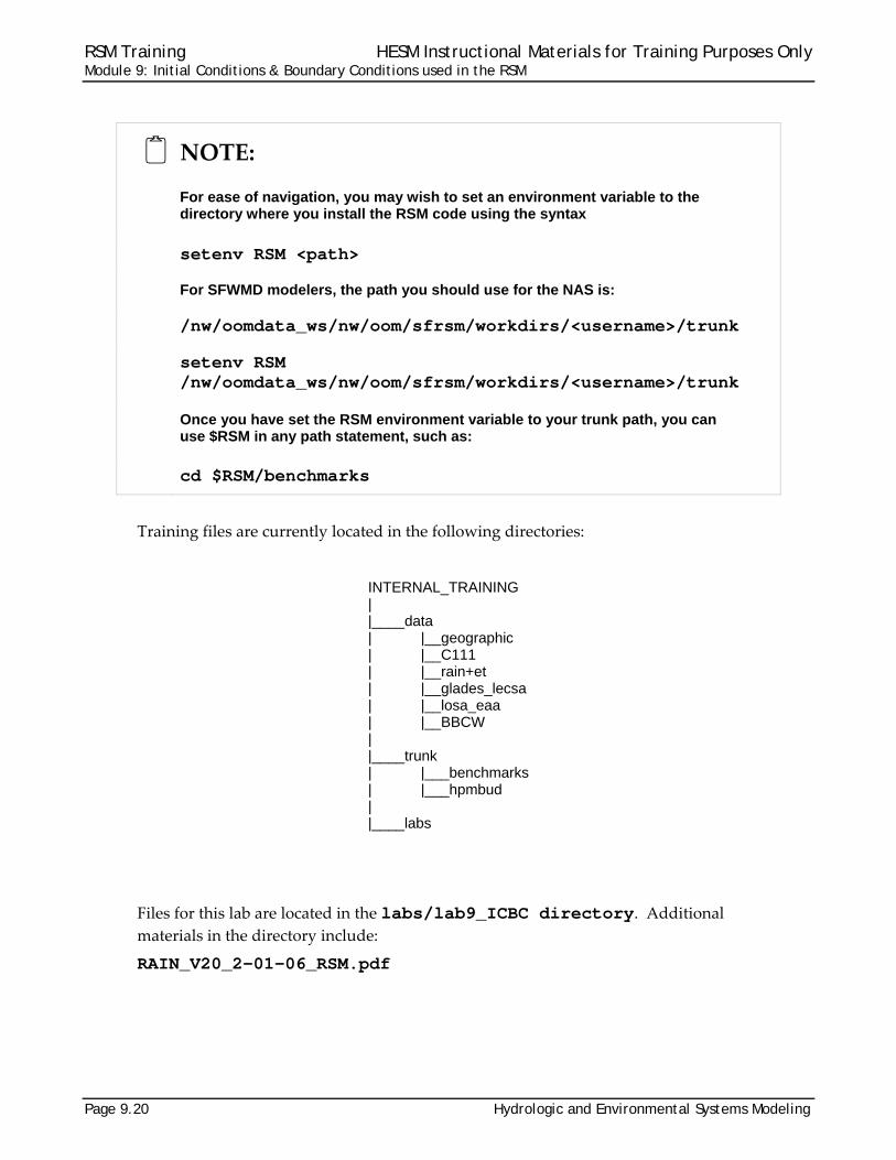
NOTE:
For ease of navigation, you may wish to set an environment variable to the directory where you install the RSM code using the syntax
setenv RSM <path>
For SFWMD modelers, the path you should use for the NAS is:
/nw/oomdata_ws/nw/oom/sfrsm/workdirs/<username>/trunk
setenv RSM /nw/oomdata_ws/nw/oom/sfrsm/workdirs/<username>/trunk
Once you have set the RSM environment variable to your trunk path, you can use $RSM in any path statement, such as:
cd $RSM/benchmarks
Training files are currently located in the following directories:
INTERNAL_TRAINING | |____data | |__geographic | |__C111 | |__rain+et | |__glades_lecsa | |__losa_eaa | |__BBCW | |____trunk | |___benchmarks | |___hpmbud | |____labs
Files for this lab are located in the labs/lab9_ICBC directory. Additional materials in the directory include:
RAIN_V20_2-01-06_RSM.pdf

RSM Training HESM Instructional Materials for Training Purposes Only Module 9: Initial Conditions & Boundary Conditions used in the RSM
Hydrologic and Environmental Systems Modeling Page 9.21
Activity 9.1: Investigate Initial Conditions and Boundary Conditions
Overview Activity 9.1 This activity includes four exercises:
Exercise 9.1.1 Look at initial conditions in Glades-LECSA RSM and C111 RSM Exercise 9.1.2 Look at boundary conditions in C111 RSM Exercise 9.1.3 Extract flow data from the SFWMM output for use as boundary
conditions Exercise 9.1.4 Look at boundary conditions in Glades-LECSA RSM
This activity investigates the initial conditions and types of boundary conditions used
in the RSM and the data sources available for subregional implementations in south
Florida.
Exercise 9.1.1 Look at initial conditions in Glades-LECSA RSM and C111 RSM
Find the distributed values for the different waterbodies used in the RSM.
Find the initial conditions for mesh cells using the Glades‐LECSA Model.
1. Open the main file
$RSM/../data/glades_lecsa/run_calib_84-95.xml
2. Find <shead> element and identify the mesh IC input dataset:
What is the apparent source of the initial conditions?
Find the segment initial conditions for the Glades‐LECSA Model.
3. Open the main file:
$RSM/../data/glades_lecsa/run_calib_84-95.xml
4. Find the <network> <initial> sub-element.
What is the data file for initial segment heads?
Find the lakes initial conditions for the C111 Model.
5. Open the main run file: $RSM/../data/C111/run_c111_mse_SR5_sss.xml
6. Find the <Lakes> element.
What is the initial head of the dummy lake?
RSM Training HESM Instructional Materials for Training Purposes Only Module 9: Initial Conditions & Boundary Conditions used in the RSM
Page 9.22 Hydrologic and Environmental Systems Modeling
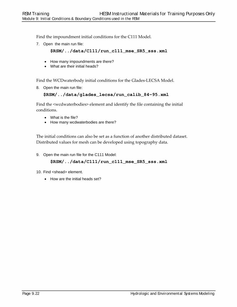
Find the impoundment initial conditions for the C111 Model.
7. Open the main run file:
$RSM/../data/C111/run_c111_mse_SR5_sss.xml
How many impoundments are there? What are their initial heads?
Find the WCDwaterbody initial conditions for the Glades‐LECSA Model.
8. Open the main run file:
$RSM/../data/glades_lecsa/run_calib_84-95.xml
Find the <wcdwaterbodies> element and identify the file containing the initial
conditions.
What is the file? How many wcdwaterbodies are there?
The initial conditions can also be set as a function of another distributed dataset.
Distributed values for mesh can be developed using topography data.
9. Open the main run file for the C111 Model:
$RSM/../data/C111/run_c111_mse_SR5_sss.xml
10. Find <shead> element.
How are the initial heads set?

RSM Training HESM Instructional Materials for Training Purposes Only Module 9: Initial Conditions & Boundary Conditions used in the RSM
Hydrologic and Environmental Systems Modeling Page 9.23
Figure 9.1 Head initial conditions for Glades-LECSA RSM subregional model network

RSM Training HESM Instructional Materials for Training Purposes Only Module 9: Initial Conditions & Boundary Conditions used in the RSM
Page 9.24 Hydrologic and Environmental Systems Modeling
Exercise 9.1.2 Look at boundary conditions in C111 RSM
There are several types of boundary conditions applied to the waterbodies in the RSM.
For cells and segments there are head, general‐head and source boundary conditions.
For other waterbodies, lakes, impoundments, basins and wcdwaterbodies, the
boundary conditions are flow conditions rather than head conditions.
In this exercise the implementation on typical RSM applications are explored. The
answers are at the end on the Lab.
1. Find the boundary conditions for segments in the C111 Model.
Open the main run file for the C111 Model:
$RSM/../data/C111/run_c111_mse_SR5_sss.xml
What is network boundary condition file? What are the boundary conditions for the canal connection to the ocean? What are the characteristics of the boundary conditions? What are the boundary conditions for the structures at the upstream structures
S-174 and S-176?
2. Find the imposed public water supply (PWS) well pumping from the aquifer.
Open the main run file for the C111 Model:
$RSM/../data/C111/run_c111_mse_SR5_sss.xml
What is the file containing the PWS boundary conditions? Where are the wells located? What are the units of time and flow? Is this a traditional outflow well or an inflow well?
3. Find the boundary conditions on the cells for the C111 Model.
Open the main run file for the C111 Model:
$RSM/../data/C111/run_c111_mse_SR5_sss.xml
What files contain the mesh boundary conditions? What is the boundary condition for the cells along the coast? What are the boundary conditions applied to the north and western sides of the
domain? Where is the time series data for the flow boundary condition?

RSM Training HESM Instructional Materials for Training Purposes Only Module 9: Initial Conditions & Boundary Conditions used in the RSM
Hydrologic and Environmental Systems Modeling Page 9.25
Figure 9.2 Location of cells and nodes in the C111 Model
4. Find the boundary conditions for the mesh in Benchmark 34 (BM34).
What are the different boundary condition types?
5. Find the boundary conditions for wcdwaterbodies in the Glades-LECSA Model?
Open the run file:
$RSM/../data/glades_lecsa/run_calib_84-95.xml
Find the wcd boundary condition files in the <mesh_bc> element: What are the boundary conditions?
6. Find the boundary conditions for an impoundment:
Open the main run file for the C111 Model:
$RSM/../data/C111/run_c111_mse_SR5.sss.xml
Are there any defined impoundment BCs in the C111 Model? Identify the waterbody ID for the impoundments. Is there a watermover that provides
water to the impoundments? Open the hse.dtd file which contains the schema for the XML input.
./RSM/trunk/benchmarks/hse.dtd
What are the allowable values for impoundment_bc?

RSM Training HESM Instructional Materials for Training Purposes Only Module 9: Initial Conditions & Boundary Conditions used in the RSM
Page 9.26 Hydrologic and Environmental Systems Modeling
7. Find boundary conditions for Lake.
Find the files describing the lakes in Benchmark 73 (BM73), the Northern Everglades RSM. Where are they?
Open the lakes_lkb.xml file and find the lake boundary conditions. What are the two types of lake boundary conditions and where are they applied?
8. Find boundary conditions for basins.
Find the files that describe the basins in Benchmark 70 (BM70), the Lake Okeechobee Service Area (LOSA) RSM. Where are the files?
Open the losa_basins.xml file and find the basin boundary conditions. What are the two types of basin boundary conditions? What are the two types of basinsource boundary conditions? Where are basinHeadBC boundary conditions applied?

RSM Training HESM Instructional Materials for Training Purposes Only Module 9: Initial Conditions & Boundary Conditions used in the RSM
Hydrologic and Environmental Systems Modeling Page 9.27
Exercise 9.1.3 Extract flow data from the SFWMM output for use as boundary conditions.
The objective of this exercise is to create groundwater flow boundary conditions from
the South Florida Water Management Model (SFWMM) datasets. A script,
getflows.scr, has been created to extract the daily groundwater and surface water
flows across each face of the cell in the SFWMM 2x2 grid and produce the total flow
across each face.
The user is still required to create a method for partitioning the flow from the 2‐mile
faces to the appropriate length of the RSM cell walls.
The output from the SFWMM exists in a binary file:
$RSM/labs/Lab9_ICBC/daily_gw_flw.bin $RSM/labs/Lab9_ICBC/daily_surface_flw.bin
The script is set up by default to produce the total flows across selected grid cell faces
for the calibration period 1984–2000. The script processes two text files that the user
creates, that include the groundwater (gw) and surface water or overland (of) flows.
Set up the script to create the boundary flows for the RSM cells 1, 3, 9, 20, 33, 50 and 75
(see Fig. 9.3). It will be necessary to extract the flows for the SFWMM grid cells 420,
320 and 220.
9. Create a new directory [test] under Lab9_ICBC
10. Copy in getflows.scr.from Lab9_ICBC
11. Edit getflows.scr:
Set dssfilename (in line7) = desired filename. Replace runpaths path list with (../ ../)
12. Create a text file that contains the required groundwater flows named: gwrocos2.txt
13. Create a text file that contains the required surface water flows named: ofrocos2.txt
gwrocos2.txt and ofrocos2.txt will contain the following lines of code.
420e;4;20;e 320e;3;20;e 220e;2;20;e

RSM Training HESM Instructional Materials for Training Purposes Only Module 9: Initial Conditions & Boundary Conditions used in the RSM
Page 9.28 Hydrologic and Environmental Systems Modeling
By convention, the direction of flow is positive north and east. Flows going south are
“sr” and flows going west are “er”.
14. Review the script getflows.scr before running
15. Run getflows.scr by entering the following command at the Linux prompt:
./getflows.scr gwrocos2.txt ofrocos2.txt
The getflow.src script produces a DSS file that contains the groundwater and surface
water flows for a 2‐mile transect. The cell sides of the RSM grid do not necessarily have
2‐mile lengths and the flows from the SFWMM must be partitioned into the
appropriate fractions for use as boundary conditions.
The preprocessing tools available for RSM do not currently include a utility for flow
partitioning, so this must be done by hand using a spreadsheet to partition the flow.
Figure 9.3 Mesh cells for the C111 Model and grid cells for the SFWMM for the southwest portion of the C111 domain

RSM Training HESM Instructional Materials for Training Purposes Only Module 9: Initial Conditions & Boundary Conditions used in the RSM
Hydrologic and Environmental Systems Modeling Page 9.29
Exercise 9.1.4 Look at boundary conditions in Glades-LECSA RSM
The purpose of this exercise is to investigate the use of the boundary conditions in the
RSM subregional implementations. Locate the following files in one of the subregional
model input directories. Open the files using the HecDssVue utility from the RSM GUI
and observe the contents.
16. Tidal head BCs:
$RSM/data/glades_lecsa/input/dss_files/RSM_TIDES_2006.dss How many stations are tabulated? What is their period of record? How many groups of boundary nodes are also used to define the tidal boundary
conditions?
17. Public water supply (PWS) wells:
$RSM/data/glades_lecsa/input/dss_files/rsm_CalibVerif_v1.2.dss How many wells are tabulated?
18. Canal and mesh stage time series:
$RSM/data/glades_lecsa/input/dss_files/all_canal_historical.dss How many records are in this file? How many sources for data? How many years of record are available for Site NP-EV7? How many years of record are available for Station S337_T?
19. Canal flow time series:
$RSM/data/glades_lecsa/input/dss_files/flow_v5.0_09122003.dss How many records? What are these data? How many years of record are available for S4? How many years of record are available for S65E?
20. Canal flow time series:
$RSM/data/glades_lecsa/input/dss_files/all_canals_bc.dss How many records are in this file? How many flow records? What are the stage data? What is the source of the stage data?

RSM Training HESM Instructional Materials for Training Purposes Only Module 9: Initial Conditions & Boundary Conditions used in the RSM
Page 9.30 Hydrologic and Environmental Systems Modeling
21. Canal flow time series:
$RSM/data/lecsaGlades/input/dss_files/daily_str_flw.dss What are these records?
NOTE:
In addition to the standard time series files found with the subregional models, there are several specialized DSS files that contain times series for local monitoring stations.

RSM Training HESM Instructional Materials for Training Purposes Only Module 9: Initial Conditions & Boundary Conditions used in the RSM
Hydrologic and Environmental Systems Modeling Page 9.31
Answers for Lab 9
Exercise 9.1.1 2. Initial conditions (ICs)
Mesh Cells: ./input/mesh/initial_cell_head_041307.dat
Source: a 1983 HSE run and historical data
4. Segments: ./input/canal/initial_canal_head_041307.dat. See Fig. 9.1 in the lab.
6. Lakes: the initial head for the dummy lake is “5.5”.
9001=5.1, 9002=5.1, 9003=5.1, 9000=5.1, 9100=5.6, 9200=5.35, 9300=5.6
7. Impoundments: There are 7 impoundments and their initial heads are:
9001=5.1
9002=5.1
9003=5.1
9000=5.1
9100=5.6
9200=5.35
9300=5.6
8. WCDwaterbodies: The file is ./input/wcd_waterbodies_init.dat and there are 69 wcdwaterbodies.
10. Mesh Cells: The initial heads are set as 0.8 times the value of the topography. This works
in the C111 model where the land elevation is very slightly above sea level.

RSM Training HESM Instructional Materials for Training Purposes Only Module 9: Initial Conditions & Boundary Conditions used in the RSM
Page 9.32 Hydrologic and Environmental Systems Modeling
Exercise 9.1.2
1. C111 network boundary conditions:
File: ./input_SR5_sss/P1R1_Alt2Db_Canal_bc.xml
Ocean connection: segment general head boundary condition
Characteristics: a time series of historical tidal heads applied to the last segment and a
conductivity of 10000 cfs/day.
The BC applied to structure S‐174 is a time series of measured historical flow.
The BC applied to structure S‐176 is a time series of simulated flow from the SFWMM
model.
2. C111 PWS boundary conditions:
./input_SR5_sss/c111_pws_11_21.xml
The wells are part of a PWS well filed located in cell 2139 and cell 2240.
The flows are monthly and the units are in million gallons per day.
The flows are withdrawals as determined by the sign on the flows.
3. C111 mesh boundary conditions:
./input_SR5_sss/mesh_bc_11_01_I0P.xml
The coastal cells have a <wallghb> that applies the daily tide time series to a list of walls
defined by a series of nodes with a conductivity of 10000.0.
The inland perimeter cells have a flow boundary condition defined a well.
The time series data is stored in ./input_SR5_sss/2005bs_bc_c111.dss
4. The mesh boundary conditions in BM34 (see Fig. 9.2) include:
wallhead with a uniform constant value
wallhead that has a value that varies from 6.9 to 6.3 according to waypoints
wallhead with a uniform head applied to two separate wall sections.
noflow wall section.

RSM Training HESM Instructional Materials for Training Purposes Only Module 9: Initial Conditions & Boundary Conditions used in the RSM
Hydrologic and Environmental Systems Modeling Page 9.33
Figure 9.2 Mesh boundary conditions for BM34, the L8 basin RSM application.
5. WCD boundary conditions:
File: $RSM/data/glades_lecsa/input/br_wcd_noflow.xml
The boundary conditions are noflow around the perimeter.
6. Impoundment boundary conditions:
There are no <impoundment_bc> defined in the C111 model.
Impoundments: 9001, 9002, 9003, 9000, 9100, 9200, 9300
Watermovers: setflow from dummy lake 40000 to 9300 and additional genxweirs that
move water between impoundments:
genxweir from 9300 to 9100
genxweir from 9100 to 9200
genxweir from 9000 to 9001

RSM Training HESM Instructional Materials for Training Purposes Only Module 9: Initial Conditions & Boundary Conditions used in the RSM
Page 9.34 Hydrologic and Environmental Systems Modeling
genxweir from 9000 to 9002
genxweir from 9000 to 9003
A search for impoundment_bc reveals that there are two possible boundary conditions:
impoundmentsource and impoundmenthead which can be implemented as time series,
rule curve or a constant value.
7. Lake boundary conditions.
The lake files are located in the $RSM/trunk/benchmarks/BM73/hse/lakes directory.
The lakeHeadBC is applied to Lake Okeechobee to fix the head to match historical data.
The lakesource is applied to the different pools of the Kissimmee River. It is applied as
one of two “packages”. What are those packages? 1) the default package that applies a
time series to the lake, and 2) “areacorrected’ package that has two area adjustments.
There is a <A> sub‐element that reduces the lake area by a fixed area which is typically
the area of the associated basin, and <B> sub‐element that reduces the lake areas by the
area of the lakes within the <B> tags. For the lakes_lkb.xml The area of lakeID=360 is
reduced by 10e+9 and the area of two other lakes; 9999 and 9998.
8. Basin boundary conditions:
The basin file is located in the $RSM/trunk/benchmarks/BM70/hse/basins directory. You want file losa_basins.xml.
There are two basin BCs: 1) basinsource, and 2) basinHeadBC.
The basinsource has two types; the default and the area corrected which reduces the area
of the basin by the area of the lakes listed in the <B> tags.
The basinHeadBC is applied to Brighton and the Lake Okeechobee public water supply.
Exercise 9.1.3
Compare results with those in the lab9_ICBC directory
Exercise 9.1.4
1. Tidal head BCs:
10 stations are tabulated
The period of record is 20 years of monthly data
16 reaches
2. Public water supply (PWS) wells:
How many wells are tabulated? 1201
3. Canal and mesh stage time series:
703 records in this file

RSM Training HESM Instructional Materials for Training Purposes Only Module 9: Initial Conditions & Boundary Conditions used in the RSM
Hydrologic and Environmental Systems Modeling Page 9.35
6 sources of data: observed, historical, Hist_DBHYDRO, Hist_MOD1, Hist_MOD2,
WMM_SIM
8 years of record are available for site NP‐EV
10 years of record are available for station S337_T
4. Canal flow time series:
148 records
These data are historical and estimated historical flows used by SFWMM
22 years of record are available for S4
36 years of record are available for S65E
5. Canal flow time series:
4619 records are in this file
361 flow records
The stage data are 4258 simulated segment head time series identified by the 6‐digit
segment number and historical head time series for head‐water and tail‐water
measurements at selected structures.
The stage data source is the SFWMM simulation.
6. Canal flow time series:
These records are daily simulated flows from the SFWMM.
They are structure flows as well as combined flows between defined waterbodies.

RSM Training HESM Instructional Materials for Training Purposes Only Module 9: Initial Conditions & Boundary Conditions used in the RSM
Page 9.36 Hydrologic and Environmental Systems Modeling

RSM Training HESM Instructional Materials for Training Purposes Only Module 9: Initial Conditions & Boundary Conditions used in the RSM
Hydrologic and Environmental Systems Modeling Page 9.37
Index aquifer .............................................. 16, 24 basin ................. 3, 8, 10, 17, 24, 26, 33, 34 BBCW, see also Biscayne Bay Coastal
Wetlands ............................................. 20 BC, see also input data - boundary
conditions .... 1, 17, 18, 19, 25, 29, 32, 34 benchmark ...................... 14, 20, 25, 26, 34
BM34 ...................................... 25, 32, 33 BM7 .................................................... 26 BM70 ............................................ 26, 34 BM73 ............................................ 26, 34
C111 model . 20, 21, 22, 24, 25, 28, 31, 32, 33
calibration ......................................... 12, 27 canal ................................................. 15, 29
connection to the ocean ...................... 24 flow ......................................... 29, 30, 35
canal, see also WCD ............ 18, 24, 29, 31 cell, see also mesh .. 2, 3, 4, 6, 8, 9, 12, 15,
16, 17, 18, 21, 24, 25, 27, 28, 31, 32 combined flows ....................................... 35 conductivity, see also hydraulic
conductivity ............................... 7, 11, 32 constant values ......................................... 5 coordinates ............................................... 4 data sources available for subregional
implementations in south Florida, see also input data ..................................... 21
datasets ................ 4, 14, 15, 16, 17, 18, 27 direction of flow ....................................... 28 distributed dataset .................................. 22 distributed values .............................. 21, 22 distribution ................................................ 1 DSSVue .................................................. 29 dummy lake ................................ 21, 31, 33 duration .................................................. 16 environment variable .............................. 20 error .......................................................... 7 ET ........................................................... 17 evapotranspiration, see also ET ............... 4 file format ................................................ 18
binary ............................................ 18, 27 DSS ........................ 5, 15, 28, 29, 30, 32 XML .......... 21, 22, 24, 25, 26, 32, 33, 34
flow .... 2, 6, 7, 8, 11, 12, 13, 14, 15, 16, 18, 21, 24, 27, 28, 29, 32, 35
flow partitioning ...................................... 28 flow rate .................................................. 16 genxweir, see also watermover .............. 33 getflows.scr ................................ 15, 27, 28 Glades-LECSA ................ 21, 22, 23, 25, 29 GMS ..................................................... 2, 3 groundwater ..................................... 27, 28
flow ..................................................... 27 gw, see groundwater .......................... 7, 27 head . 2, 3, 6, 7, 8, 9, 10, 11, 16, 18, 21, 24,
31, 32, 34, 35 boundary condition ..............2, 10, 16, 32
historical data .. 2, 12, 14, 29, 31, 32, 34, 35 how to
create a method for partitioning flow ... 27 create groundwater flow boundary
conditions ........................................ 27 produce total flow across a grid face .. 27
HPM ................................................... 2, 20 water budget ....................................... 20
HSE ........................................................ 31 hse.dtd file .............................................. 25 IC, see also initial conditions ...1, 19, 21, 31 imposed pumping ................................... 24 impoundment ... 2, 3, 10, 17, 22, 24, 25, 31,
33, 34 inflow ...................................................... 24 initial head ............. 3, 17, 18, 21, 22, 23, 31 input data ............................................... 10
boundary conditions .. 1, 2, 5, 6, 7, 10, 11, 12, 13, 14, 15, 17, 18, 19, 21, 24, 25, 26, 27, 28, 29, 32, 33, 34
boundary conditions – general head ... 24 flow ................................ 2, 14, 16, 21, 27
input files .......................................... 17, 21 initial conditions ........... 17, 18, 21, 22, 23
inundation ................................................. 2 lake .............. 2, 3, 10, 17, 21, 24, 26, 31, 34 Lake Okeechobee ............................ 26, 34 Lake Okeechobee Service Area, see also
LOSA .................................................. 26 lake, see also waterbody .................. 26, 34 levee ................................................... 6, 18 Linux ....................................................... 28 local monitoring stations ......................... 30

RSM Training HESM Instructional Materials for Training Purposes Only Module 9: Initial Conditions & Boundary Conditions used in the RSM
Page 9.38 Hydrologic and Environmental Systems Modeling
LOSA, see also Lake Okeechobee Service Area .................................................... 26
mesh .... 2, 3, 4, 6, 7, 10, 11, 15, 16, 17, 18, 21, 22, 24, 25, 28, 29, 31, 32, 33, 34 boundary ............................................... 7 boundary conditions ............................ 33 node ................................ 6, 9, 25, 29, 32
model input, see input data .................... 29 network ............. 2, 3, 10, 11, 21, 23, 24, 32
boundary condition .............................. 32 no-flow boundary condition .... 2, 5, 6, 7, 17,
18, 32, 33 Northern Everglades RSM ...................... 26 note .............................................. 7, 20, 30 outflow .................................................... 24 output data ................................... 7, 18, 27
water budget ......................................... 7 partition the flow ..................................... 28 pre-processing tools ............................... 28 public water supply, see also pws .... 29, 34 pws ....................................... 24, 29, 32, 34 rainfall ........................................... 4, 18, 20 raw data .................................................. 14 reference ET, see also ET ...................... 18 Regional Simulation Model, see also RSM
........................................................ 1, 19 regional system ........................................ 2 RSM
implementation ................ 1, 2, 14, 15, 29 RSM GUI ................................................ 29 RSM, see also Regional Simulation Model
1, 2, 5, 14, 15, 16, 17, 18, 19, 20, 21, 22, 23, 24, 25, 26, 27, 28, 29, 30, 33, 34
rulecurve ................................................... 7 script ........................................... 15, 27, 28 seepage .................................................. 10 segment
boundary condition .............................. 11 head .............................................. 21, 35 segmenthead ................................ 11, 12 segmentsource ............................. 11, 12
segment, see also waterbody segment .............. 2, 3, 11, 21, 24, 32, 35
setenv ..................................................... 20 setflow .............................................. 13, 33 SFWMM ... 2, 12, 13, 14, 15, 18, 21, 27, 28,
32, 35 grid ...................................................... 27 output ............................................ 21, 27
simulated flows ....................................... 35 source boundary .................................... 24 South Florida Water Management Model,
see also SFWMM ........................... 2, 27 spatial variability ....................................... 3 stage ................... 2, 5, 7, 14, 16, 29, 34, 35
data ......................................2, 16, 29, 35 schedule ............................................... 7
structure .............. 11, 13, 15, 18, 24, 32, 35 S176 ............................................. 24, 32
subregional models ..... 2, 16, 18, 23, 29, 30 surface hydrology ..................................... 2 surface water .................................... 27, 28
flows ............................................. 27, 28 text file .................................................... 27 tidal head, see also input data ... 12, 29, 32,
34 time series 2, 4, 5, 9, 10, 11, 12, 13, 14, 16,
18, 24, 29, 30, 32, 34, 35 time step ................................................... 4 topography ....................................... 22, 31 transect .................................................. 28 uniform head .......................................... 32 upstream structure ................................. 24 user-specified watermover, see also
watermover ......................................... 10 utilities .............................................. 28, 29 wallhead ....................................... 7, 18, 32 Water Control District ............................. 16 water supply ..................................... 16, 18 waterbody 2, 3, 5, 10, 13, 21, 24, 25, 31, 35 watermover ................... 2, 8, 11, 13, 25, 33 watershed ................................................. 2 WCD, see also Water Control District 2, 18,
25, 31, 33 well ........ 6, 8, 14, 16, 18, 24, 29, 32, 34, 35
pumping .............................................. 24