initiation conditions for debris flows generated by … conditions for debris flows generated by...
TRANSCRIPT

Available online at www.sciencedirect.com
2008) 270–297www.elsevier.com/locate/geomorph
Geomorphology 96 (
Initiation conditions for debris flows generated by runoff atChalk Cliffs, central Colorado
Jeffrey A. Coe a,⁎, David A. Kinner b, Jonathan W. Godt a
a U.S. Geological Survey, Denver Federal Center, MS 966, Denver, Colorado 80225, United Statesb Geology Program, Department of Geosciences and Natural Resources Management, Western Carolina University,
Cullowhee, North Carolina 28723, United States
Received 6 September 2006; received in revised form 8 March 2007; accepted 8 March 2007Available online 10 May 2007
Abstract
We havemonitored initiation conditions for six debris flows betweenMay 2004 and July 2006 in a 0.3 km2 drainage basin at ChalkCliffs; a band of hydrothermally-altered quartz monzonite in central Colorado. Debris flows were initiated by water runoff fromcolluvium and bedrock that entrained sediment from rills and channels with slopes ranging from about 14° to 45°. The availability ofchannel material is essentially unlimited because of thick channel fill and refilling following debris flows by rock fall and dry ravelprocesses. Rainfall exceeding I=6.61(D)−0.77, where I is rainfall intensity (mm/h), and D is duration (h), was required for theinitiation of debris flows in the drainage basin. The approximate minimum runoff discharge from the surface of bedrock required toinitiate debris flows in the channels was 0.15 m3/s. Colluvium in the basin was unsaturated immediately prior to (antecedent) andduring debris flows. Antecedent, volumetric moisture levels in colluvium at depths of 1 cm and 29 cm ranged from 4–9%, and 4–7%,respectively. During debris flows, peak moisture levels in colluvium at depths of 1 cm and 29 cm ranged from 10–20%, and 4–12%,respectively. Channel sediment at a depth of 45 cm was unsaturated before and during debris flows; antecedent moisture ranged from20–22%, and peak moisture ranged from 24–38%. Although we have no measurements from shallow rill or channel sediment, weinfer that it was unsaturated before debris flows, and saturated by surface-water runoff during debris flows.
Our results allow us to make the following general statements with regard to debris flows generated by runoff in semi-arid toarid mountainous regions: 1) high antecedent moisture levels in hillslope and channel sediment are not required for the initiation ofdebris flows by runoff, 2) locations of entrainment of sediment by successive runoff events can vary within a basin as a function ofvariations in the thickness of existing channel fill and the rate of replenishment of channel fill by rock fall and dry ravel processesfollowing debris flows, and 3) rainfall and simulated surface-water discharge thresholds can be useful in understanding andpredicting debris flows generated by runoff and sediment entrainment.Published by Elsevier B.V.
Keywords: Debris flow; Flood; Colorado; Erosion; Bedrock; Channel; Entrainment; Bulking; Rainfall; Threshold; Antecedent; Soil moisture; Rockfall; Dry ravel; Surface-water discharge
⁎ Corresponding author. Tel.: +1 303 273 8606; fax: +1 303 2738600.
E-mail address: [email protected] (J.A. Coe).
0169-555X/$ - see front matter. Published by Elsevier B.V.doi:10.1016/j.geomorph.2007.03.017
1. Introduction
Runoff, erosion, and sediment entrainment areimportant mechanisms for the initiation of debrisflows in burned and unburned basins throughout the

271J.A. Coe et al. / Geomorphology 96 (2008) 270–297
world (e.g., VanDine, 1985; Wohl and Pearthree, 1991;Takahashi, 1991; Davies et al., 1992; Berti et al., 1999;Cannon, 2001; Hürlimann et al., 2003; Griffiths et al.,2004; David-Novak et al., 2004; Godt and Coe, 2007).The initiation processes, and thus, the hazard implica-tions for runoff-generated debris flows are different fromdebris flows initiated by the mobilization of landslides(e.g., Iverson et al., 1997; Iverson et al., 2000), and aremuch less studied and understood (Tongnacca andBezzola, 1997; Cannon et al., 2003; Berti and Simoni,2005). In addition to the lack of a physical framework foranalyzing these types of debris flows, common problemsthat inhibit an understanding of initiation conditionsinclude: a lack of rain gages in small basins where debrisflowsmost commonly occur; rain gages that inaccuratelymeasure rainfall from short, intense bursts, commonduring thunderstorms; little or no knowledge of ante-cedent rainfall and sediment moisture conditions; andpoor constraints on times of occurrence.
To examine initiation conditions and processes forrunoff-generated debris flows in unburned areas, webegan studying four debris flow basins in centralColorado in May 2004 (Coe et al., 2005). All of thebasins are small (b0.5 km2), steep (25–90° hillslopes),sparsely vegetated, at least partially south facing, andhave had recent debris flow activity. In each basin, wehave made multiple sets of field observations, monitoredinitiation-conditions using event-recording rain gagesand dielectric soil moisture sensors, and measured andmodeled hydrologic characteristics and discharge fromcolluvium and bedrock in zones where debris flows areinitiated.
This paper focuses on one of the four study basins; thebasin located at Chalk Cliffs (Figs. 1 and 2). Like manylow-order (or “steepland”) basins in the semi-arid, westernUSA, the Chalk Cliffs basin contains two primary types ofhillslope materials: exposed bedrock and sandy colluviumwith little soil development. Multiple debris flows haveoccurred in this basin since May 2004, but none of theseflowsmobilized from discrete landslide sources (i.e., slidesor spreads using the Varnes, 1978 classification). Severalwater-dominated events (floods) have also occurred in thebasin since May, 2004. Although this paper is focused ongaining a better understanding of the debris flows, we alsoattempt to distinguish debris flows from floods using thepreviously mentioned data sets.
Our hypothesis is that the frequent initiation of debrisflows in the Chalk Cliffs study basin is dependent on theability of bedrock and/or colluvium to produce surfacerunoff during rainfall, and the availability of sedimentthat can be easily entrained by runoff. An additionalhypothesis is that the magnitude of debris flows (i.e.,
travel distance or volume) is positively correlated withrainfall amounts or the elapsed time since the last debrisflow, which would control the amount of sedimentavailable for entrainment. In this paper, we examinethese hypotheses using the previously mentioned datasets, and follow with a discussion of our results in thecontext of previous work and the implications for runoffdebris flow initiation processes in general.
2. The Chalk Cliffs study area
The Chalk Cliffs are highly fractured and hydro-thermally-altered quartz monzonite, which is part of theEocene–Oligocene Mount Princeton batholith. Thecliffs are located in the Sawatch mountain rangeadjacent to a normal fault which forms the easternboundary of the range (Miller, 1999). Slip along thenormal fault is associated with formation of the RioGrande Rift and cumulative displacement is estimatedat about 3000 m since 23 Ma (Tweto, 1978; Shannonet al., 1987; Kelley, 1991). The most recent faultmovement occurred within the last 3 ka (Ostenaa et al.,1981). Several hot springs are located along the normalfault and are apparently the remnants of the hot watersystem that caused the extensive hydrothermal alter-ation observed in the area (Sharp, 1970). The name“Chalk Cliffs” is derived from the white color of lau-montite and leonhardite (a calcium zeolite variety oflaumontite), which are two of the most abundant alte-ration minerals in the area. Other alteration mineralsinclude chlorite, calcite, illite, epidote, quartz, kaolinite,and fluorite (Sharp, 1970; Emslie, 1991).
The Chalk Cliffs drainage basin that wemonitored forthis study (Fig. 2) is a tributary of Chalk Creek; an eastflowing, formerly glaciated, perennial stream. Coalesc-ing fans (bajadas) line the north and south sides of ChalkCreek, but the bajada at the base of Chalk Cliffs isparticularly extensive (Figs. 1A and 2). Deposits fromhistorical debris flow activity are prevalent on this bajadaat and near the mouths of many of the small drainagebasins in Chalk Cliffs (Figs. 1A and 2). A systematiccompilation of historical debris flows in the area does notexist, but several studies have noted the abundance ofrecent debris flows from basins in the area (Dillon andGrogger, 1982;Mortimer, 1997).Mortimer (1997) foundthat railroad tracks built on the bajada in 1882 wereburied by several meters of sediment from multipledebris flows and floods.
The study basin is small (0.3 km2) and steep; bedrockslopes range from roughly 40° to vertical, whereascolluvial slopes range from about 25° to 40°. Bedrock isexposed in about 60% of the basin area (Fig. 2).

272 J.A. Coe et al. / Geomorphology 96 (2008) 270–297
Colluvium forms an apron downslope from bedrock cliffsand is thickest (roughly 10 m) near the center of the basin.Colluvial areas adjacent to bedrock gulleys are beingactively eroded by runoff from the surface of bedrockduring rainstorms. Colluvium adjacent to channels hasbeen incised, is oversteepened, and supplies material tothe channels by raveling. All channels in the basin, and onthe downslope bajada, flow intermittently during rain-storms. The main channel that drains the basin extendsabout 940 m (measured horizontally) from the mouth ofthe basin, across the bajada and Chaffee County Road 162(CCR162), to form a fan in Chalk Creek (Figs. 1A and 2).Where the channel crosses CCR162 (Fig. 2), ChaffeeCounty has widened and lined the channel with concrete.Signs along the road on both sides of the channel warnmotorists not to drive through the channel when it isflowing. When debris flows deposit material on the road,the county cleans off the road and hauls away the debris.According to county maintenance records, such cleaningis needed, on average, about once a year (Joe Nelson,2004, personal communication). A comparison of theAverage Recurrence interval (ARI) between debris flowsin the study basin (ARI≤1 year), with the level in otherwell known debris flow basins areas in Colorado (e.g.,Cascade Creek near Ouray, ARI≈5 years, Jochim, 1986;two unnamed basins near Georgetown, ARI≈7 years,Coe et al., 2003), indicates that the study basin probablyhas the highest observed frequency of debris flows inColorado.
Several recent investigations by Eric Leonard and hisstudents at Colorado College in Colorado Springs, COindicate that flows from the study basin are water-dominated flows and debris flows (Mortimer, 1997), andthat the velocities of debris flows range from about 4 to13 m/s (Christensen, 2003). Based on these estimates ofvelocity, the time required for a debris flow to travel fromthe mouth of the basin to the CCR162 (about 820 m)ranges from about 1 to 3 min.
3. Field and laboratory methods
To examine our hypothesis that debris flows aregenerated by surface runoff from bedrock and/orcolluvium during rainfall, we used a combination offield and laboratory methods to characterize the arealextent and physical properties of surficial geologicmaterials (colluvium and channel sediment), accuratelymeasure rainfall within the basin, and measure andcharacterize the hydrologic response of surficial materi-als to rainfall. We used field observations, geologicmapping, and measurements of grain size and in-situbulk density to characterize the physical properties of
surficial materials. A rain gage was used to monitorrainfall in the basin. Soil moisture sensors and in-situinfiltrometer and permeameter measurements were usedto characterize the hydrologic response of surficialmaterials to rainfall. Field observations following debrisflows were used to estimate travel distances and relativemagnitudes of the volumes of debris flows (i.e., absolutedebris flow volumes were not measured) to evaluate oursecond hypothesis, that is, that the magnitude of debrisflows is correlated with rainfall amounts or the elapsedtime since the last debris flow. The timing and magni-tude of runoff (i.e., surface-water discharge) frombedrock was simulated using a routing model and isdescribed in Section 4.
3.1. Field observations and geologic mapping
We made field observations in the study basin and onthe downslope fan twelve times between May, 2004 andJuly, 2006. Observations were sometimes made duringtrips to install or repair instrumentation in the basin, butwere often made following notification of a flow bylocal residents. Observations typically involved deter-mining the extent of the flows, interviewing localresidents and authorities to determine the timing ofevents, following the tracks of flows to the source in thebasin to determine characteristics of flow initiation andflow initiation zones, sampling material from flowdeposits and source areas, and geologic mapping ofbedrock and colluvium. Geologic contacts were identi-fied on aerial photographs in the field, and thentransferred from the photographs to a topographic basemap using a PG2 photogrammetric plotter (Pillmore,1989).
3.2. Field instrumentation
We installed two types of instruments in the studybasin, a rain gage and four soil moisture probes. The raingage is a siphoning, tipping bucket rain gagemanufacturedby Hydrologic Systems and designed to maintain ±2%accuracy at rainfall rates up to 500 mm/h. We installed thegage near the center of the basin on a relatively stable talussurface at an elevation of about 2800 m (R1, Fig. 3). Thesoil moisture probes are capacitance-based, ECH20 soilwater probes manufactured by Decagon Devices, Inc. Thedimensions of the probes are 25 cm×3 cm×0.1 cm. Theprobes measure the apparent dielectric constant of soilwithin a 2 cm soil zone on both sides of the flat,25 cm×3 cm surface and relate the measured constant tovolumetric water content through the use of a calibrationequation. Bosch (2004) rigorously tested the probes and

273J.A. Coe et al. / Geomorphology 96 (2008) 270–297
found that they yielded very accurate estimates ofvolumetric water content (within ±0.05 cm3/cm3) whenthey were calibrated for specific soils. We developed acalibration equation for our probes using soils sampledfrom soil pits during installation of the probes, andlaboratory techniques outlined by Campbell (2004). Thelinear calibration equation used for this study is:
vw ¼ 0:0007ðmVÞ � 0:2519 ð1Þwhere vw is volumetric water content and mV is millivoltsmeasured by the probe with an excitation voltage of2.5 volts at 10 milliamps for 10 milliseconds.
We installed probes at two locations, on a colluvialmantled hillslope in young colluvium (SM1, SM2, Fig. 3),and in/near the main drainage channel within the basin(SM3, SM4, Fig. 3).On the hillslope, a soil pit was dug andslope-parallel slots for the probes were driven into theupslope wall of the pit using a steel blade with the samedimensions as the probe. The probes were installed in theslots so that the narrow (0.1 cm) edges of the probes wereapproximately parallel to the slope of the surface. Probeswere installed at two slope-normal depths, 1 cm (SM1) and29 cm (SM2), where depth is measured to the uppermost,narrow edge of the probe. After installation, the pit wasfilled with the same material that was initially removed. Inthe channel, a probe was installed as described above at adepth of 45 cm (SM4). Along the edge of the channel, aprobe was installed within a debris flow levee at a depth of1 cm (SM3).
3.3. Field and laboratory tests to characterize collu-vium, channel sediment, and debris flow deposits
3.3.1. Grain size analysesWe collected samples for grain size analyses from
colluvium in debris flow source areas, (G3, G5, G6, Fig. 3),channel sediments (G2, G4), and fresh debris flow deposits(G1). Samples were analyzed using sieve and hydrometermethods as described in American Society for Testing andMaterials (ASTM) standard D-422.
3.3.2. Bulk densityWe measured the bulk density of the colluvium in the
study basin at three locations (BD1–BD3, Fig. 3) usinga Ring-Excavation technique (Grossmann et al., 2001;Grossman and Reinsch, 2002). An aluminum ring ofapproximately 20 cm in diameter was driven into thecolluvial surface. The depth to the ground surface withinthe ring was measured in about 16 locations using amicrometer and a small shelf placed across the ring.The colluvium inside the ring was then excavated
using a spoon and the distance measurements wererepeated. The volume of colluvium was then deter-mined using the difference between the two sets ofdistance measurements and the cross-sectional area ofthe ring. The porosity and void ratios (ratio of voidvolume to volume of solid particles) were calculatedfrom the oven dried mass of the colluvium using aspecific gravity of 2.65.
3.3.3. Measurements of infiltrationWe made mini-disk tension infiltrometer measure-
ments on in-situ colluvium at 5 locations (I1–I5, Fig. 3) toestimate the rate of infiltration of the colluvial surface at amatrix tension head of−6 cm relative to atmospheric. Thetension of −6 cm allows measurement of the rate of waterinfiltration into the colluvium as it approaches saturation,but prior to ponding of water on the surface, therebysimulating anticipated conditions directly before a debrisflow. A sample of colluvium was collected nearby eachmeasurement site prior to the test tomeasure the initial soilmoisture, and a sample was collected directly underneaththe disk after the test to measure the final soil moisture.The samples were dried over-night at 105 °C to determinethe gravimetric soil moisture.
3.3.4. Permeameter measurementsWe used a Guelph permeameter (a constant head well
permeameter manufactured by Soilmoisture EquipmentCorporation, Reynolds and Elrick, 2002) to measure thesaturated hydraulic conductivity of colluvium at threelocations (Ksg1–Ksg3, Fig. 3) in the study basin. Thehydraulic conductivity values obtained using this methodare generally assumed to represent a “field-saturated”hydraulic conductivity where the soil is not fully saturatedbut contains some entrapped air (Elrick and Reynolds,1992). In general, the saturated conductivity measured inthe field using permeameter techniques is assumed to beabout half that measured in the laboratory on the samematerials using large samples and de-aired water(Bouwer, 1966). To compute the field-saturated hy-draulic conductivity of the colluvial material, we usedthe multiple-head analyses of Reynolds et al. (1985)and the single-head analysis or “Glover” analysis(Zangar, 1953; Amoozegar, 1989). Reynolds and Elrick(2002) provide a detailed discussion of both data re-duction methods.
4. Modeling to characterize runoff from bedrock
One of our hypotheses was that runoff-generated onbedrock drives the initiation of debris flows at ChalkCliffs. Like other studies that have used simple models

Fig. 1. Photographs showing the Chalk Cliffs study basin. A) Oblique aerial photograph taken in August, 2002. View to the west. Elevation of fan atmouth of study basin in Chalk Creek is about 2500 m. B) Ground based photograph taken on May 27, 2004. View to the northwest. Relief shown isabout 420 m.
274 J.A. Coe et al. / Geomorphology 96 (2008) 270–297
to test hypotheses (i.e. Piñol et al., 1997; Kinner andStallard, 2004), this study used a routing model toexamine the possible flood hydrographs that were
created by various rainstorms producing debris flowsand floods. Without observed discharge to verify themodeling, our results were compared to field-observed

Fig. 2. Map showing the Chalk Cliffs study basin and the areal extent of bedrock and colluvium. Base map from U.S. Geological Survey 1:24,000-scale Mount Antero quadrangle, contour interval, 40 ft (12 m). Coordinates shown are UTM zone 13, units are meters. Darkly shaded areas arehistorical debris flow deposits.
275J.A. Coe et al. / Geomorphology 96 (2008) 270–297
constraints which provide guidance on the timing andmagnitude of runoff.
We used a routing model that accompanies theprogram RiverTools (Rivix, 2001), called TOPOFLOW,to simulate the timing and magnitude of runoff createdon bedrock. Simulated runoff was examined at themouth of the west channel (Fig. 3), a 4th order bedrockchannel, before it entered the sediment-laden mainchannel (Fig. 3, near G3 and G5), a 5th order channelthat drains to Chalk Creek. We chose this point forsimulating runoff because the upslope drainage area isalmost entirely bedrock (Fig. 3) and the downslope area
is loose sediment. The main channel downslope fromthe simulation point consistently contains sediment thatcan be entrained by runoff, unlike the west channel,which intermittently contains sediment. We assignedstream orders based on field observations that orders 1and 2 were small rills and gulleys on bedrock cliffs andhillslopes, and order 3 was the first level of well-developed bedrock channels that merge to form the 4thorder channels shown in Fig. 3.
TOPOFLOW models overland flow by mass balanceusing Manning's equation applied to a mesh of gridcells. The equations used for routing in TOPOFLOW
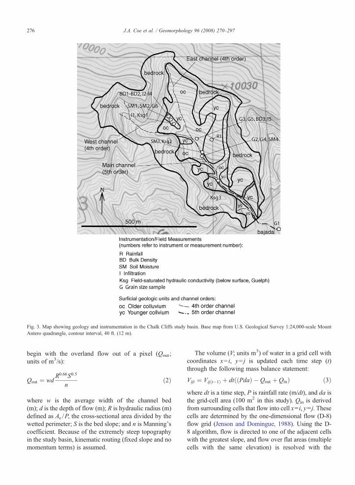
Fig. 3. Map showing geology and instrumentation in the Chalk Cliffs study basin. Base map from U.S. Geological Survey 1:24,000-scale MountAntero quadrangle, contour interval, 40 ft. (12 m).
276 J.A. Coe et al. / Geomorphology 96 (2008) 270–297
begin with the overland flow out of a pixel (Qout ;units of m3/s):
Qout ¼ wdR0:66S0:5
nð2Þ
where w is the average width of the channel bed(m); d is the depth of flow (m); R is hydraulic radius (m)defined as Ac /P, the cross-sectional area divided by thewetted perimeter; S is the bed slope; and n is Manning'scoefficient. Because of the extremely steep topographyin the study basin, kinematic routing (fixed slope and nomomentum terms) is assumed.
The volume (V; units m3) of water in a grid cell withcoordinates x= i, y= j is updated each time step (t)through the following mass balance statement:
Vijt ¼ Vijðt�1Þ þ dtððPdaÞ � Qout þ QinÞ ð3Þwhere dt is a time step, P is rainfall rate (m/dt), and da isthe grid-cell area (100 m2 in this study). Qin is derivedfrom surrounding cells that flow into cell x= i, y= j. Thesecells are determined by the one-dimensional flow (D-8)flow grid (Jenson and Domingue, 1988). Using the D-8 algorithm, flow is directed to one of the adjacent cellswith the greatest slope, and flow over flat areas (multiplecells with the same elevation) is resolved with the

Fig. 4. Recent rock fall and dry ravel deposits in an unnamed 4th order channel northwest of Ksg3. Snow is about 40 days old. Photograph takenFebruary 28, 2006. View to the northwest. See circled rock hammer for scale.
277J.A. Coe et al. / Geomorphology 96 (2008) 270–297
imposed gradients plus algorithm (Garbrecht and Martz,1997; Rivix, 2001). Given a resolved flow grid, Qin istherefore defined:
Qin ¼Z 8
c¼1xcQoutc ð4Þ
where c are adjacent cell numbers 1–8 and xc is a binaryvector that is either 1 (flows into the cell) or 0 (does notflow into the cell).
TOPOFLOW inputs are a time series of observedrates of rainfall, a catchment slope grid and flow gridderived from a USGS 10-m DEM, and three stream-order varying parameters: Manning's n (m−0.33 s),channel width (m), and channel side slope (m/m).Calculation of stream order begins at the catchmentboundary and, thus, includes bedrock hillslope (orders 1and most of 2) and bedrock channels (orders 3 and 4).
The procedure we used for defining Manning's ngroups for first to fourth order channels is as follows.The n value for a non-vegetated, relatively smoothoverland flow surface is 0.01 to 0.02 (Emmett, 1978)and rock channels are generally assigned a value of0.025 to 0.035 (Chow, 1959), so the value n=0.025 isassigned to first and second order flowpaths. For steepbedrock channels, like those of third and fourth order,critical flow is often assumed in estimating discharge(Moody and Martin, 2001), requiring that velocity (v) isdefined:
v ¼ffiffiffiffiffigd
pð5Þ
where g is gravitational acceleration, 9.8 m/s2. To fit thecritical flow assumption within the structure of TOPO-FLOW, critical flow was assumed for different depths of

Fig. 5. Rock fall, dry ravel, and channel sediments in 5th order, main channel near SM3 and Ksg2 (see Fig. 3 for location). View to south. Width offield of view at foreground is about 4 m. Photograph taken February 28, 2006.
278 J.A. Coe et al. / Geomorphology 96 (2008) 270–297
flow (0.1 m and 0.5 m) given the average slope fordifferent scale channels (3rd order S=1.78; 4th orderS=0.55). Given the critical flow velocity, the slope and anestimated depth, the equivalent Manning coefficient canbe calculated. The coefficient values for 3rd and 4th orderchannels were set to 0.90 and 0.16, respectively.
We also defined channel dimensions by order.Hillslope cells (orders 1 and 2) have flowpath widths of10 m or the cell width. Because planar flow for hillslopecells was assumed, channel banks were assumed to haveangles of 0 (i.e., no banks). Widths of bedrock channelswere estimated based on field observations. Bedrockchannels are roughly 2mwide in the area being simulated,so a 2-m channel width was assumed for third and fourthorder channels. Additionally, many of the channels havesteep or vertical banks sowe assumed a bank angle of 90°.
TOPOFLOW has several outputs at each cross-section, including depth of flow and discharge.Simulated velocity was also monitored to make surethat the flow estimates were reasonable.
5. Results
5.1. Geologic mapping and physical properties ofgeologic materials
Geologicmapping (Fig. 3) revealed five geologic unitswithin the study basin; bedrock; young loose colluvium
on and near (generally at depths less than 0.5 m) thesurface (yc, Fig. 3); underlying, older compactedcolluvium that has been exposed by erosion and ravelingtriggered by channel incision (oc, Fig. 3); channelsediment from debris flows or floods; and recent colluvialfill in channels. Channel sediment and colluvial fill are notshown because of limitations of map scale for Fig. 3.Mapping also showed that the 4th and 5th order channelswithin the basin (those shown on Fig. 3) all begin withinbedrock or at the bedrock/oc contact. The bedrock cliffswere the original source for all four surficial geologicunits in the basin.
Bedrock forms steep cliffs in the basin, but has beenhighly altered by hydrothermal activity and containsabundant mineralized veins and barren fractures. Thecombination of weakened ground mass and abundantdiscontinuities makes the bedrock highly susceptible torock fall. Rock falls were observed during every trip to thebasin and ranged from rates of 5 to 20 falls per hour. Thetiming and frequency of rock falls appeared to be at leastpartially controlled by thermal expansion associated withexposure to sunlight. We observed this process one wintermorning in February 2006. We arrived in the basin beforedirect sunlight reached the exposed bedrock slopes in theupper basin and did not observe any rock-fall activity.Immediately after direct sunlight hit the bedrock slopes,however, rock falls began to occur at a rate of about 20 perhour. When these falling rocks impacted colluvial slopes,

Fig. 6. Colluvium in the study basin. A) Bedrock cliff, older colluvium (oc), and young colluvium (yc) near the head of the basin. View to thenorthwest. Relief shown is about 120 m. Evergreen tree is also visible in B. B) Sandy yc and bedrock. Width of field of view at foreground is about3 m. View to the northwest. C) Coarse yc (talus) at rain gage R1 (see Fig. 3 for location). View to the northeast. D) oc with rills near instrumentationSM3, Ksg2. Width of field of view at foreground is about 4 m. View to the east.
279J.A. Coe et al. / Geomorphology 96 (2008) 270–297

Table 1Dry bulk density, porosity, and void ratio of colluvium in the studybasin (see Fig. 3 for site locations)
Site name and description Dry bulkdensity (g/cm3)
Porosity Voidratio
BD1 — colluvial surface (yc) nearSM1 and SM2
1.10 0.58 1.41
BD2 — colluvial surface (yc) nearI2
1.21 0.54 1.19
BD3 — raveling colluvium (oc)near I5
1.46 0.45 0.81
Fig. 7. Results from grain size analyses.
280 J.A. Coe et al. / Geomorphology 96 (2008) 270–297
they caused dry sediment to ravel (Gabet, 2003) to down-slope positions in channels.
The 4th order channels have exposed bedrock at thesurface, or at a shallow (b0.5 m) depth. The amount ofsediment in the 4th order channels is a function of theelapsed time since the last flow. When sediment ispresent, we estimate (from field observations) that about10% of the sediment has been previously moved bydebris flows or floods, and that about 90% is colluvialfill deposited by rock fall and dry ravel processes. Ourobservations of rock fall and dry ravel deposits on top ofone month old snow during the winter of 2005/2006(Fig. 4), and after debris flows that flush out the chan-nels, indicate that the channels quickly fill through theformation and expansion of colluvial wedges along thechannel banks (Figs. 4 and 5).
A major break in slope occurs where the 4th orderchannels feed into the 5th order channel. The averageslope of the 4th order channels is about 40°, whereas theaverage slope of the 5th order channel is 14° in the basin,and 9° on the bajada. During the monitoring period, the5th order channel in the basin was continuously lined bythick (generallyN3 m) rock fall, dry ravel, debris flow,and flood deposits (Fig. 5). Our observations followingdebris flows (described in the next section) indicate thatthe 5th order channel is the sediment source for theinitiation of debris flows when the 4th order channels aredepleted of sediment.
Young colluvium (yc) tends to fall into two cate-gories, either talus, or a poorly sorted mix of sand-,
gravel, and cobble-sized sediment (Fig. 6). Both cate-gories of yc are loose and uncompacted. The underlying,older colluvium (oc) is a poorly sorted mix of sedimentranging in size from silt to boulders (Fig. 6). Resultsfrom grain size analysis indicate that the matrix of bothtypes of colluvium is similar, that is, a sediment domi-nated by gravel and sand, with less than 6% silt and clay(Fig. 7). Older colluvium (oc) has a higher density thanyounger colluvium (yc) probably because it was buried(i.e., compacted from overlying colluvium and/or snowand ice during Pleistocene glaciation) prior to exposure.Bulk density results (Table 1) confirm this fieldobservation and show that oc has a higher bulk density(1.46 g/cm3), and lower porosity (0.45) and voidratio (0.81) compared to yc, which has bulk densitiesthat range from 1.10 to 1.21, porosities from 0.58 to0.54, and void ratios from 1.19 to 1.41. Uncertainties

281J.A. Coe et al. / Geomorphology 96 (2008) 270–297
associated with measured volumes and assumed specificgravities of sediment samples suggest that errors in bulkdensity, porosity, void ratio values given in Table 1 areabout ±20%.
Material in channels is either sediment that has beenpreviously mobilized by debris flows or floods, or freshcolluvial fill. Both types of sediment are loose andunconsolidated (Figs. 4 and 5). Channel sediment hassimilar grain size characteristics to colluvium, exceptthat it contains a lower percentage silt and clay (b2%,versus b6% for colluvium, Fig. 7). A visual comparisonof channel materials (Figs. 4 and 5), with both types ofcolluvium (Fig. 6), strongly suggests that the channelsediment has lower bulk density and higher porosityvalues than colluvium. We estimate that channelmaterials have a minimum porosity of about 0.5.
Table 2Flows during the monitoring period
Date Time (MountainDaylight Time,MDT)
Source of timing information
July 24, 2004 Approximately21:30
Bob Warren, US Forest Serviceemployee who lives in Chalk Ca
August 18, 2004 Approximately18:30
Joe Nelson, head of Chaffee CouRoad Maintenance Group
September 25, 2004 Roughly 20:30,but poorly defined.
Eric Dahlberg, manager of SilverRanch adjacent to the channel.
September 22, 2005 Approximately16:30
Eric Dahlberg, manager of SilverRanch adjacent to the channel.
October 18 orOctober 19, 2005
Late on the 18th orearly on the 19th
Eric Dahlberg, manager of SilverRanch adjacent to the channel.
May 22, 2006 Between 20:30and 21:30
No eyewitness information, tconstrained based on dates ofobservations and available storm
July 8, 2006 Approximately14:00
Travis Collins, Chaffee CountyRoad Maintenance Group
July 26 or27, 2006
July 26th orJuly 27th
Observations from July 28 andinformation from local resident
5.2. Field observations following debris flows andfloods
Field observations and interviews with local resi-dents and county authorities indicate that at least sixdebris flows and two floods occurred in the study basinbetween May 2004 and July 2006 (Table 2). Althoughwe did not directly observe any of these flows, we wereable to classify them as predominantly debris flows orfloods based on the type of deposits that we observedsoon after they occurred.
Of the six debris flows, three of the flows traveled toChalk Creek and deposited fans in the creek, and theother three either stayed in the basin, or stopped in thechannel on the bajada near the mouth of the basin. Wevisited the study area within several days following two
Dominanttype of flow
Comments
nyonDebris flow Debris flow(s) traveled the length of the 5th
order channel, crossed CR 162, and deposited asmall fan in Chalk Creek
nty Debris flow Debris flow(s) traveled the length of the 5thorder channel, crossed CR 162, and deposited alarge fan in Chalk Creek. Field observationsindicated that the volume of this flow wasroughly an order of magnitude larger than theJuly 24, 2004 flow.
Cliff Possibledebris flow
Possible debris flow(s), but CR 162 is apparentlynot affected and timing is poorly constrained.
Cliff Debris flow Debris flow(s) travels about halfway down the5th order channel and stops upslope of CR 162.
Cliff Water-dominatedflow (flood)
Field observations of deposits indicated that theflow was water-dominated. Flood traveled thelength of the 5th order channel, crossed CR 162,and progressed to Chalk Creek, but no fan wasdeposited. Small debris flow tracks and depositswere observed on colluvium in the basin, but notin the primary channel.
imingfield
s
Debris flow Debris flow restricted to 4th order channels athead of the basin.
Debris flow Debris flow(s) traveled the length of the 5thorder channel, crossed CR 162, and deposited amoderate-sized fan in Chalk Creek. Fieldobservations indicated that the volume of thisflow was smaller than the August 18, 2004 flow,but larger than the July 24, 2004 flow.
Water-dominatedflow (flood)
Flood traveled the length of the 5th orderchannel, crossed CR 162, and progressed toChalk Creek, but no fan is deposited. Smalldebris flow tracks and deposits were observed oncolluvium in the basin, but not in the 5th orderchannel.

282 J.A. Coe et al. / Geomorphology 96 (2008) 270–297
of these flows (the July 24, 2004 and May 22, 2006flows, Table 2), and walked from Chalk Creek to thesource areas of the debris flows near the head of thestudy basin (Fig. 2). The July 24 flow traveled to ChalkCreek whereas the May 22 flow only traveled to thejunction of the west and east 4th order channels near thehead of the basin (see Fig. 3). Debris flow deposits inChalk Creek from the July 24 flow were fan shaped andpartially blocked the flow of the creek. The depositswere matrix supported, poorly sorted, and containedabundant clasts up to 0.3 m in diameter. In the channelon the bajada, we observed debris flow levees, debrisflow runup zones around channel bends, and multiple,often overlapping, lobate deposits (Fig. 8). The depositswere similar to those on the fan in the creek, both werepoorly sorted and matrix supported, and contained clastsup to about 0.3 m in diameter. No evidence was ob-served that the debris flows incised and entrained sedi-ment along the thalweg of the previously existingchannel on the bajada.
In the basin, sediment was mobilized during debrisflows along the length of the 4th order channels whereabundant loose debris existed from recent rock fallsand dry ravel of colluvial deposits (Fig. 9), as well asalong the 5th order channel near the junctions with the4th order channels (Fig. 10). Some minor rilling andassociated, small debris flow deposits were observed
Fig. 8. Debris flow deposits in 4 m-wide main channel on bajada. Photographcenter of channel.
on exposed older colluvial deposits (oc, e.g., Fig. 6D),but none were observed on younger deposits (yc). Wefound no evidence for slides that mobilized into debrisflows in any of the source areas, although we didobserve some small slides in colluvial wedge depositsthat had been undercut by erosion along the flanks ofchannels. The debris flows initiating on oc were verysmall, with individual volumes of flow much less than1 m3 (Fig. 6D). The heads of the rills above thedeposits tended to be within or immediately downslopefrom cobble- and boulder-rich patches of colluvium.The lack of slides at the head of the rills indicates thatthe debris flows initiate through sediment entrainmentin the rills themselves (Fig. 6D). On bedrock exposedat the heads of 4th order channels, we found evidencefor overland flow of water, sediment entrainment, andtransformation into debris flows in the form of preservedlevees flanking rills and gulleys on sideslopes that werethinly (1–2 cm) mantled by fresh dry ravel deposits (e.g.,Fig. 9B). A sequence of photographs of the western 4thorder channel taken throughout the monitoring period(Fig. 11) show that debris flows occurred as a series ofpulses (some of which are still preserved in place in thephotographs) that entrained sediment and scoured thechannel to bedrock, and that the channel quickly refilledfollowing the debris flows. In the 5th order channel, thetruncation of fresh debris flow deposits by well-sorted
taken July 25, 2004. View to south. Note post-debris flow incision in

Fig. 9. Debris flow source areas in 4th order channels. See Fig. 3 for locations. A) Bedrock catchment area at the head of thewest channel. Lower portion ofphotograph is also shown in Fig. 11. Relief shown is about 300m.View to the northwest. Photograph taken on July 28, 2006. B)Rill with debris flow leveeson thinly mantled bedrock at head of east channel. View to north. See hammer for scale. Photograph taken onMay 26, 2006. C) Freshly scoured portion ofwest channel with debris flow levee. Also shown in Fig. 11. View to northwest. Channel in foreground is about 2 m wide. Photograph taken on July 25,2004, one day after a debris flow. D) Channel to southwest of SM4. Relief shown is about 120 m. View to southwest. Photograph taken on July 28, 2006.
283J.A. Coe et al. / Geomorphology 96 (2008) 270–297

Fig. 10. Debris flow source area in 5th order channel between BD3 andmouth of west channel (see Fig. 3 for location). Width of channel inforeground is about 3 m. Photograph taken on July 25, 2004.
284 J.A. Coe et al. / Geomorphology 96 (2008) 270–297
sandy deposits indicates that some water-dominated,recessional flow occurred immediately after each debrisflow (e.g., Fig. 8).
We also made field observations within several daysafter the two floods of October 19, 2005 and July 27,2006. At Chalk Creek, and in the 5th order channel on thebajada, the floods were characterized by the redistributionand sorting of sediment that was previously deposited bydebris flows (Fig. 12). Also in the channel, incision andtruncation of existing debris flow deposits was observed.In the basin, we observed evidence for water-dominatedflow and debris flows, although we still classified theoverall events as floods because the debris flow depositswere relatively minor. In 5th order channels in the basin,water-dominated flows incised the channel and undercutand eroded away colluvial wedge deposits along thechannel flanks. Avariety of deposits were observed in the4th order channels in the basin. Debris flow deposits wereobserved in the upper-most portions of some channels,and minor rilling and small debris flow deposits wereobserved on oc. Unlike the three debris flows that wepreviously described, the debris flow deposits associatedwith the floods were only present in the upper portions ofthe 4th channels (e.g., Fig. 9D), and were not present inthe 5th order channel.
5.3. Rainfall
Rainfall that triggered debris flows and floods in thebasin (Fig. 13) occurred between late spring (May) andearly fall (October) each year. No debris flows or floodswere triggered by snowmelt. In typical years, about 50%of the average annual precipitation (345 mm, Fig. 13A)in the basin falls between May and September, withJuly, August, and September tending to have the mostintense storms.
Eyewitness reports indicate that flow events tended tobe triggered by rainstorms with durations of much lessthan 1 h. Because of these observations, and because ourintent was to develop a rainfall threshold for triggeringflows, we divided the rainfall record (Fig. 13A) intoindividual periods of high-intensity rainfall, which wecall storm “bursts” (Fig. 13B). We define a burst as asegment of a storm that has less than 10 min gapsbetween rain gage bucket tips. If the gap between buckettips is greater than 10 min, then a new burst is defined.Thus, by our definition, storm bursts have intensitiesgreater than 1.52 mm/h, which would be the intensitycalculated from 1 bucket tip every 10 min. Results fromthis exercise (Fig. 13B) reveal that the rainfall thresholdfor triggering the observed debris flows is:
IB ¼ 6:61ðDBÞ�0:77 ð6Þ
where burst intensity, IB, is in mm/h and burst duration,DB, is in hours. Several of the bursts triggered debrisflows in 4th order channels (October 19, 2005 andJuly 27, 2006), and triggered floods in the 5th orderchannel. These two bursts are distinguished from theother bursts by long (2.4 h, October, 19, 2005) and short(0.3 h, July 27, 2006) durations. Although the burststriggering floods can be distinguished from the burststriggering debris flows by duration times, the actualchannel response is a function of the generated runoff(i.e., discharge) and the availability of sediment inchannels. Both of these topics will be explored in a latersection.
Also, no easily distinguishable difference existsbetween bursts that triggered debris flows with longtravel distances (July 24, 2004, August 18, 2004, andJuly 8, 2006) and those that triggered debris flows withshort travel distances (September 25, 2004; September22, 2005; and May 22, 2006). The only commonalitybetween bursts that triggered debris flows with longtravel distances is that the duration is between 0.55 and0.65 h. Bursts with shorter and longer durations resultedin debris flows with shorter travel distances. Again,these differences may be more accurately explained by
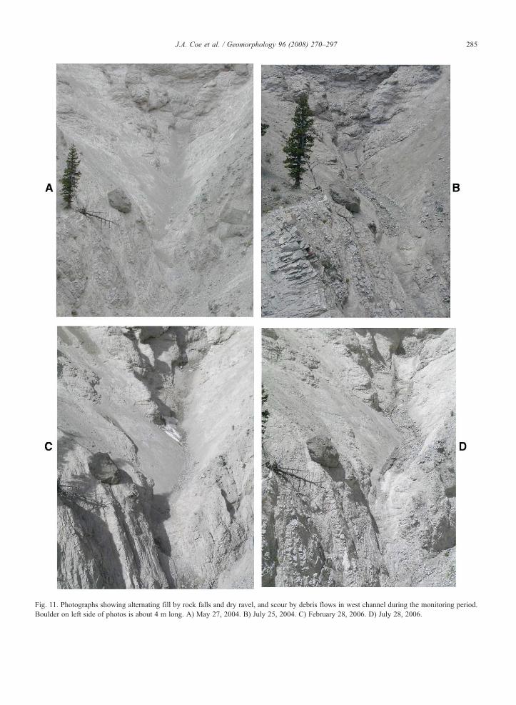
Fig. 11. Photographs showing alternating fill by rock falls and dry ravel, and scour by debris flows in west channel during the monitoring period.Boulder on left side of photos is about 4 m long. A) May 27, 2004. B) July 25, 2004. C) February 28, 2006. D) July 28, 2006.
285J.A. Coe et al. / Geomorphology 96 (2008) 270–297

Fig. 12. Photographs showing flood deposits in main channel on bajada (see Figs. 2 and 3 for location). View is upstream to the northwest. Width offresh deposits in foreground is about 2 m. Photograph taken on October 21, 2005.
286 J.A. Coe et al. / Geomorphology 96 (2008) 270–297
differences in generated runoff and the availability ofsediment in channels.
5.4. Soil moisture
Records of soil moisture are available for three debrisflows and two floods between May 2005 and August2006 (Fig. 14A). Expanded records for individual flowsare shown in Fig. 14B to F. Moisture on the hillslope, inthe channel levee, and at depth in the 5th order channel,immediately prior to triggering rainstorms (antecedentmoisture), was always less than 22%moisture by volume(Fig. 14). The lowest porosity measured for colluvium inthe study area was 0.45 (45%) (Table 1); therefore,sediment was always unsaturated at the beginning ofrainstorms that triggered flows. At depths of 1 cm on thehillslope and in the levee, antecedent moisture rangedbetween 4 and 9% (Fig. 14). At a depth of 29 cm on thehillslope, antecedent moisture ranged between 4 and 7%(Fig. 14). Although few data are available from the 5thorder channel, antecedent moisture at a depth of 45 cmranged from about 20–22% (Fig. 14B and C), the highestantecedent moisture levels of any of the monitored sites.
Peak moisture levels during flows were also low(Fig. 14B–F), with peak shallow (1 cm) moisture rangingfrom about 10–20%, hillslope moisture at 29 cm rangingfrom 4 to 12%, and channel moisture at 45 cm rangingfrom 24 to 38%. As with antecedent moisture, all of the
peak moisture levels indicate unsaturated conditions atmonitoring sites during flows. Interestingly, the hillslopemoisture sensor at 29 cm (SM2, Fig. 3) did not showan increase in moisture during three of the five flows(Fig. 14B, D, and F), and showed a moisture increase ofonly a few percent within a day following the other twoflows (Fig. 14C and E).
Distinguishing debris flows from floods is difficultbased on the soil moisture records alone. The moisturelevels are very similar for both types of flows, exceptthat the limited records (two events) of channel moisture at45 cm suggest that deep channelmaterials arewetter duringfloods than during debris flows (compare Fig. 14C to B).
Unfortunately, because of practical limitations (i.e.,possible destruction of sensors by flows) we do not haveany moisture measurements from shallow channel mate-rials. Field observations of shallow channel materials,however, suggest that antecedent moisture levels weresimilar to those in colluvium (i.e., sensors SM1 andSM2). In 4th order channels, where shallow materialswere consistently mobilized by runoff, moisture levelsduring floods and debris flows were likely at or nearsaturation. Moisture levels of shallow sediment in the5th order channel during floods and debris flows areunknown. Additionally, local areas of shallow, olderhillslope colluvium (oc, Fig. 3) where rilling occurredduring flows, was also likely saturated, but only verynear the surface.

Fig. 13. Diagrams showing rainfall during the monitoring period collected at rain gage R1 (see Fig. 3 for gage location). A) Cumulative rainfall fromstarting date of May 27, 2004. B) Rainfall bursts and debris flow threshold.
287J.A. Coe et al. / Geomorphology 96 (2008) 270–297
5.5. Hydrologic characterization of colluvium andchannel sediment
Results from Guelph and Mini Disk field measure-ments indicate that hydraulic conductivity (Ks) andinfiltration (I) increases as progressing from older collu-
vium (oc), to younger colluvium (yc), to channel sediment(Table 3 and Fig. 15). Guelph measurements indicate thatfield-saturated Ks ranges from 58 to 101 mm/h for yc and504 to 864 mm/h for channel and levee sediments(Table 3). Values for yc are about two times greater thanthe highest rainfall intensity that triggered debris flows
288 J.A. Coe et al. / Geomorphology 96 (2008) 270–297
(27.4 mm/h, August 18, 2004, Fig. 13B), whereas valuesfor channel sediments are about 18 to 31 times higher. Wedid not make Guelph measurements in older colluvium(oc) because abundant pebbles and cobbles made it verydifficult to auger a bore hole with geometrically stablesides (a requirement for Guelph measurements). Instead,we relied on Mini Disk measurements for estimates ofinfiltration at the surface of oc.
Results from theMini diskmeasurements show that ochas a lower rate of infiltration than yc (Fig. 15). The rate ofinfiltration measured for the matrix of oc is about 26 mm/h, which is close to the maximum rainfall intensities thattriggered debris flows (∼ 27 mm/h), whereas the rates foryc are greater than 43 mm/h (Fig. 15). Small variations(several percent) in initial soil moisture at each site mayhave partially contributed to the observed rate differences;but overall, the results suggest that differences exist in thehydrologic properties of two types of colluvium.
5.6. Modeled runoff response
Modeled runoff at the mouth of the 4th order, westchannel (Fig. 3), provides an indication of how rainfalltranslates into peak-flow discharge. The estimated peakdischarges of surface-water indicate the potential forrunoff to entrain sediment once it encounters loosesediment. To better understand the effect that variablesediment supply had on the generation of debris flows,we plotted modeled peak-flow discharge against thetime since last flow (Fig. 16). One of our hypotheseswas that the magnitude of debris flows (i.e., traveldistance, volume) would be positively correlated withthe elapsed time since the last flow. Results shown onFig. 16 indicate that this hypothesis is incorrect, becausetwo of the largest debris flows (August 18, 2004; July 8,2006, Table 2) occurred after some of the shortestelapsed times (Fig. 16). Fig. 16 also suggests that debrisflows occur at an approximate minimum peak dischargethreshold of 0.15 m3/s.
Fig. 16 does a reasonably good job of distinguishingfloods from debris flows. Both floods occurred withelapsed times (i.e., time since previous debris flow) of lessthan 30 days since the last flow. One debris flow (August18, 2004) also occurred with an elapsed time of less than30 days (24 days), but this debris flow resulted from thestorm with the highest intensity (27 mm/h, Fig. 13B) andthe highest modeled peak discharge (∼ 0.62 m3/s,Fig. 16). These observations suggest that floods aremost likely when elapsed times are less than 30 days, butthat debris flows are also possiblewith short elapsed timesif the rainfall burst intensity is well above the rainfallthreshold. Interestingly, the two rainfall bursts that
resulted in floods had very different durations. Onestorm had a very short duration (0.3 h, Fig. 13B) and onehad a long duration (2.4 h, Fig. 13B), but the modeledpeak discharge response was very similar (Fig. 16).
6. Discussion — debris flow initiation
A summary of initiation conditions for debris flowsin the study basin is given in Table 4. These resultsindicate that debris flows are triggered by short duration,moderate to high intensity rainfall (see threshold inFig. 13) that results in overland flow from unsaturated,consolidated older colluvium, and steep bedrock cliffs.Interestingly, the rainfall threshold for Chalk Cliffs isvery similar to thresholds developed by Cannon et al.(2008-this volume) for areas recently burned by wild-fires in Colorado. The Cannon thresholds, however,only apply for one year after a fire (i.e., until vegetationbecomes reestablished on burned slopes), whereas theChalk Cliffs threshold is for long-term conditions.During the monitoring period, an average of two debrisflows occurred per year in the study basin. Becauseshort recurrence rainstorms trigger debris flows at ChalkCliffs on a regular basis, the site as an ideal naturallaboratory to study debris flows generated from runoff.
Debris flows on older colluvium (oc) initiate throughsediment entrainment in rills. The rate of infiltrationmeasured for the matrix of oc (see I5, Fig. 15) is roughly26 mm/h. This suggests that most bursts of rainfallwould not result in runoff from the oc matrix, but thatconcentrated runoff from cobbly/bouldery patches couldeasily exceed the infiltration capacity of the matrix andcreate rills. Moisture levels in colluvium immediatelybefore and during debris flows were low; between 4 and20% by volume. Debris flows initiating from colluviumcontribute sediment to the 4th and 5th order channelswhere it can be entrained by large debris flows, but thesevolumes are very small compared to the amount ofsediment that is entrained from the 4th and 5th orderchannels by runoff from bedrock.
Whether or not debris flows are initiated in the 4thorder channels (Figs. 9 and 11) appears to depend on theavailability of sediment in the channel. Field observa-tions indicate that the channels fill rapidly from rock falland dry ravel. Two successive debris flows occurred in2004 within 24 days of one another, although the secondof these debris flows probably formed from entrainmentof sediment from the 5th order channel, rather than fromthe 4th order channel. All of the 4th order channels haveheads within or immediately adjacent to bedrock.Runoff from bedrock is water-rich and sediment poorand when runoff reaches sediment lined-channels,

289J.A. Coe et al. / Geomorphology 96 (2008) 270–297
sediment is entrained in the flow and debris flows aregenerated. Field observations of debris flow levees nearthe heads of the 4th order channels indicate that
Fig. 14. Soil moisture data during the monitoring period. See Fig. 3 for instrrecord because of problems maintaining the sensor because of channel eNovember and April are from freezing and thawing of shallow colluvium. Se2005. B–F) Data from individual flow events.
sediment entrainment occurs quickly and that debrisflows are formed within the first several meters of waterflowing over the sediment.
ument locations. A) All available data. Note that SM4 is only a partialrosion and rodents. Large fluctuations in shallow moisture betweennsor SM1 was partially exposed to air between June 15 and August 14,

Fig. 14 (continued ).
290 J.A. Coe et al. / Geomorphology 96 (2008) 270–297
Hungr et al. (2005) suggest that two main mechan-isms are responsible for sediment entrainment inchannels; bed destabilization and erosion, and failureof stream banks undercut by erosion. Both types occurin the study basin. As stated previously, two types of 4th
order channels occur in our study area, those that beginat the bedrock/colluvial contact (Fig. 9D), and those thatbegin on bedrock (Fig. 9A). The entrainment process isdifferent for each type of channel. For channels thatbegin at the bedrock/colluvial contact, entrainment

Fig. 14 (continued ).
291J.A. Coe et al. / Geomorphology 96 (2008) 270–297

Table 3Field-saturated hydraulic conductivity determined from Guelphpermeameter measurements in colluvium in the study basin (see Fig. 3for site locations)
Site name, description Depth(cm)
Ks(cm/s)
Ks(mm/h)
Type ofsolution
Ksg1, yc near SM1and SM2.
19 1.6×10⁻³ 58 Multi-head
Ksg1, yc near SM1and SM2
19 2.8×10⁻³ 101 Single-head
Ksg2, channel andlevee sediments
13 1.4×10⁻² 504 Single-head
Ksg2, channel andlevee sediments
30 2.4×10⁻² 864 Multi-head
Ksg2, channel andlevee sediments
30 1.5×10⁻² 540 Single-head
Ksg3, recentlydeposited channelsediments
12 1.9×10⁻² 684 Single-head
292 J.A. Coe et al. / Geomorphology 96 (2008) 270–297
occurs during a “firehose effect” where water-richrunoff from gulleys in bedrock cliffs pours ondownslope colluvium. The firehose effect has beendescribed in many previous studies (e.g., Fryxell andHorberg, 1943; Johnson and Rodine, 1984; Coe et al.,1997; Glancy and Bell, 2000; Larsen et al., 2006; Godtand Coe, 2007), although the actual mechanics of theprocess are poorly understood. Our new insights intothis process are that high antecedent moisture levels arenot required for the initiation of debris flows and that thelocation of the entrainment sites can change as a
Fig. 15. Diagram showing results from measurements of infiltration. See Figfrom 9 to 12%.
function of the conditions of sediment supply (seediscussion of 5th order channels later in this section).Furthermore, entrainment occurs nearly instantaneouslyupon impact, as we have observed debris flow leveesimmediately adjacent to impact points (Fig. 9D).
For channels that begin within bedrock, entrainmentappears to occur through the progressive increase insediment concentration of runoff along the thalwegs ofthe channels (Figs. 9 and 11). Previous work indicatesthat the level of moisture in soils and sediments isimportant in controlling soil cohesion (Fredlund et al.,1978; Matsushi and Matsukura, 2006) and the efficiencyof erosion by overland flow (Huang et al., 2001).Although we do not have soil moisture data from thethin sediments in any of our studied 4th order channels,we know from numerous field observations that moisturelevels of sediments in the channels are similar to moisturelevels in colluvium, which are always unsaturated prior todebris flows. Therefore, high antecedent moisture levelsin sediment in the 4th order channels are not a prerequisitefor the initiation of debris flows at Chalk Cliffs. Afterrainfall and runoff begins, however, sediment along thethalwegs of the 4th order channels undoubtedly becomesquickly saturated. Once this sediment is moving as adebris flow, further sediment is added to the flow by bankfailures of colluvial wedge deposits (dry ravel and rock-fall deposits). Once debris flows are moving, observationsof deposits in the channels (e.g., Fig. 11) indicate that theyoccur as pulses or waves, rather than as single, massivedebris flows.
. 3 for measurement locations. Initial soil moisture for all tests ranged

Fig. 16. Diagram showing modeled peak discharge for rainfall bursts during the monitoring period. Large gap in data between 60 and 230 daysrepresents late fall to early spring periods of time.
293J.A. Coe et al. / Geomorphology 96 (2008) 270–297
Sediment supply controls where debris flowsinitiate in the study basin. Bovis and Jakob (1999)indicated that the conditions of sediment supply indebris flow basins are fundamental to understandingand predicting debris flows and this is certainly thecase in the study basin. During short periods (perhaps60 days or less) in most summers, the 4th orderchannels in the study basin are depleted of sedimentbecause of flushing by debris flows. When thresholdexceeding rainfall occurs during these sediment-depleted times, water-rich runoff, rather than debrisflows, flows into the 5th order channel. When thisoccurs, field observations indicate that sedimententrainment occurs in the 5th order channel at andnear its junction with 4th order channels (Fig. 10).The sediment in the 5th order channel is at least 3 mthick, and is consistently supplied with fresh dry raveland rock-fall deposits. We therefore consider thesupply of sediment in the 5th order channel to beessentially unlimited. We hypothesize that this is whydebris flows can occur in the basin so close togetherin time, because an adequate supply of sedimentalways exists.
These 4th and 5th order channel junctions alsotend to be major breaks in slope; most 4th orderchannels have an average slope of about 40°, whereasthe 5th order channel has about a 14° slope. Because
of this major break in slope, at least part of theentrainment process at the channel junctions isprobably by the firehose process. Once debris flowshave formed and are flowing in the 5th order channel,field observations indicate that channel incision andfurther entrainment of material by the debris flowsthemselves are minimal. These observations are ingeneral agreement with observations by Rickenmann etal. (2003) and Iverson et al. (2005). Rickenmann et al.(2003) conducted field and laboratory debris flowexperiments and observed that channel erosion duringdebris flows tended to be inversely related withsediment concentration. That is, more fluid rich flowstended to erode and entrain greater amounts of channelmaterial. Iverson et al. (2005) conducted flumeexperiments and found that steady water floods anddam-break floods (which we consider to be roughlyequivalent to a firehose effect), entrained sediment andtransformed into debris flows.
Based on modeling simulations, our estimate forthe minimum amount of runoff discharge required toinitiate debris flows is about 0.15 m3/s (Fig. 16).Although this appears to be a fairly low threshold, acomparison to an empirical threshold for specificsurface-water runoff discharge (QT) required toinitiate debris flows from sediment in channels(proposed by Tognacca et al., 2000), suggests that it

Table 4Summary of results
Date, typeof event in5th orderchannel
Rainfallburstintensity(mm/h),duration (h)
Maximumtraveldistance (m)
Antecedenthillslopesoil moistureat 1 cm depth(volumetricpercent)
Antecedenthillslope soilmoisture at29 cm depth(volumetricpercent)
Antecedentchannel soilmoisture at45 cm depth(volumetricpercent)
Elapsed timesince previousflow event(days)
Modeled peakdischarge fromwest channel atintersection witheast channel (m3/s)
July 24, 2004,Debris flow
13.34, 0.53 1700 Notavailable
Notavailable
Notavailable
N265 0.18
August 18, 2004,Debris flow
27.43, 0.58 1700 Notavailable
Notavailable
Notavailable
24 0.62
September 25,2004, Debris flow
16.46, 0.42 b1400 Notavailable
Notavailable
Notavailable
37 0.21
September 22,2005, Debris flow
10.57, 0.82 1220 7 4 20 362 0.15
October 18 orOctober 19, 2005,Flood
5.95, 1.37 1700 (flood),b100 (small debrisflows in basin)
8 7 20 26 (for previousdebris flow)
0.15
May 22, 2006,Debris flow
26.49, 1.08 300 4 5 Notavailable
215 (for previous flood),242 (for previousdebris flow)
0.41
July 8, 2006,Debris flow
9.63, 0.63 1700 7 4 Notavailable
262 (for pervious flood),47 (for previousdebris flow)
0.16
July 27, 2006,Flood
25.40, 0.25 1700 (flood),b100 (small debrisflows in basin)
9 5 Notavailable
280 (for previous flood),18 (for previousdebris flow)
0.21
294 J.A. Coe et al. / Geomorphology 96 (2008) 270–297
is not. The threshold of Tognacca et al. (2000) isdefined as:
QT ¼ qsqw
� 1
� �0:5⁎ðg0:5Þ⁎ d1:5m
ðtanhÞ1:17 !
ð7Þ
whereQT is a specific discharge expressed as discharge perunit length of channel (m2/s), ρs and ρw are the densities(kg/m3) of channel sediment and water (1000 kg/m3), g isgravitational acceleration (9.81 m/s2), dm is the mean grainsize (m) of channel sediment, and θ is the slope angle(degrees) of the channel.
For the modeled 4th order channel in the study basin,the channel width is about 2 m, and the mean grain size isabout 0.01 m. Given the channel width, our modeleddischarge threshold of 0.15 m3/s yields a specificdischarge threshold of about 0.075 m2/s. Using valuesof ρs=2650 kg/m3 and θ=40° in Eq. (7), the QT for the4th order channels is about 0.005 m2/s, well below ourmodeled specific discharge threshold of 0.075 m2/s.Performing the same calculation for the 5th order channel,with a θ=14°, yields aQTof 0.020 m
2/s, which is also wellbelow our modeled specific discharge threshold. Thisindicates that debris flows may be initiated in this largerchannel even in the absence of overland flow fromcolluvium; flow off bedrock is likely enough to create
debris flows. Additionally, we interpret these results tomean that small-scale sediment entrainment probablybegins at specific discharge values less than 0.075 m2/s,but that the 0.075 value is reasonable for large scaleentrainment that is easily noticeable and hazardous. Anexample of small-scale entrainment that probably oc-curred at specific discharges less than 0.075 m2/s is thesediment entrainment in rills on older colluvium in thebasin (see Fig. 6D). For these rills, the parameters used inEq. (7) are essentially the same as those used for the 4thorder channel.
7. Conclusions
Our observations indicate that debris flows in the ChalkCliffs study basin were initiated when rainfall createdsurface runoff from consolidated colluvium and steepbedrock cliffs. This runoff transformed into debris flowsby entraining sediment in rills and channels throughfirehose and progressive bulking processes. The type andlocation of entrainment processes were dynamic anddepended on variations in sediment supply and channelgeometries. Debris flows, initiating in rills on colluvium,had flow volumes smaller than 1 m3 and tended to belocated immediately downslope from cobble- and boulder-rich patches in the colluvium. These small debris flows

295J.A. Coe et al. / Geomorphology 96 (2008) 270–297
supplied sediment to 4th and 5th order channels, wherewater runoff from bedrock transformed channel sedimentinto larger debris flows. Between debris flows, thesechannels were rapidly refilled by rock falls from cliffs andby dry ravel from incised colluvial deposits. Duringperiods when sediment was temporarily depleted in steep,4th order channels, sediment was available in the 5th orderchannel that drains the entire basin. Therefore, givenadequate rainfall, debris flows occurred in sequence oververy short time frames. The shortest time between debrisflows during the monitoring period was 24 days.
Debris flows were initiated by rainfall exceedingI=6.61(D)−0.77, where I is rainfall intensity (mm/h),and D is duration (h). The approximate minimum runoffdischarge required to entrain channel sediment is0.15 m3/s. Colluvium in the basin was unsaturatedimmediately prior to, and during debris flows. Ante-cedent, volumetric moisture levels in colluvium atdepths of 1 cm and 29 cm ranged from 4–9%, and 4–7%, respectively. During debris flows, peak mois-ture levels at 1 cm and 29 cm ranged from 10–20%,and 4–12%, respectively. Channel sediment at a depthof 45 cm was unsaturated before and during debrisflows; antecedent moisture ranged from 20–22%, andpeak moisture ranged from 24–38%. Although we haveno measurements from shallow rill and channelsediment, we infer that it was unsaturated before debrisflows, and saturated during debris flows.
Some results from this study are applicable to othersemi-arid to arid mountainous regions that experiencedebris flows triggered by short-duration, moderate-to-high intensity rainstorms. First, our results show thathigh antecedent moisture levels in hillslope and channelsediment are not required for debris flows initiated byrunoff. Surface-water runoff from bedrock can rapidlyentrain loose sedimentwith very lowmoisture levels (about4–10% in this study). Second, locations of entrainment ofsediment by runoff (i.e., debris flow initiation) can varywithin a basin as a function of variations in the thickness ofchannel fill and the refilling of channels (following debrisflows) by rock fall and dry ravel processes. In basins withmultiple sources of loose sediment (i.e., 4th and 5th orderchannels in this study), or where channels are quicklyreplenished from hillslopes, the time between successivedebris flows can be very short, especially when rainfallbursts exceed rainfall thresholds by large amounts. Theintensity of the rainfall burst that triggered the debris flowwithin 24 days of the previous flow in this study exceededthe threshold value by about 2.5 times. That said, it appearsthat water-dominated flows (floods) are most likely inwindows of time immediately following debris flowswhensediment supplies are at least somewhat reduced. Both
floods documented in this study occurred within 30 days ofa debris flow and were triggered by rainfall bursts that wereonly slightly above rainfall threshold values (burst intensityvalues were within 5 mm/h of threshold values). Lastly, asdemonstrated in this study, a combination rainfall andsimulated surface-water discharge thresholds can be usefulin understanding and predicting debris flows generated byrunoff and sediment entrainment.
Acknowledgements
We thank Cherokee Pursall for developing thecalibration equation for the soil moisture probes, XavierAmblard and Jon McKenna for conducting the grainsize analyses, and Bill Schulz for help with the Guelphhydraulic conductivity measurements. Eric and LetaDahlberg, Bob Warren, Joe Nelson, and Travis Collinsprovided debris flow timing information. We aregrateful to Mark Reid, Fausto Guzzetti, Mario Parise,Paul Santi, Jack Vitek, and Gerry Wieczorek for theirthoughtful, constructive reviews of this paper.
References
Amoozegar, A., 1989. Comparison of the Glover solution with thesimultaneous-equations approach for measuring hydraulic con-ductivity. Soil Science Society of America Journal 53, 1362–1367.
Berti, M., Simoni, A., 2005. Experimental evidences and numericalmodeling of debris flow initiated by channel runoff. Landslides 2,171–182.
Berti, M., Genevois, R., Simoni, A., Tecca, P.R., 1999. Fieldobservations of a debris flow event in the dolomites. Geomorphol-ogy 29, 265–274.
Bosch, D.D., 2004. Comparison of capacitance-based soil waterprobes in coastal plain soils. Vadose Zone Journal 3, 1380–1389.
Bouwer, H., 1966. Rapid field measurement of air entry value andhydraulic conductivity of soil as significant parameters in flowsystem analysis. Water Resources Research 2 (4), 729–738.
Bovis, M.J., Jakob, M., 1999. The role of debris supply conditions inpredicting debris flow activity. Earth Surface Processes andLandforms 24, 1039–1054.
Campbell, C.S., 2004. Calibrating ECH2O Soil Moisture Probes.Decagon Application Note, Decagon Devices, Inc., Pullman,Washington. 4 pp.
Cannon, S.H., 2001. Debris-flow generation from recently burned water-sheds. Environmental and Engineering Geoscience VII (4), 321–341.
Cannon, S.H., Gartner, J.E., Parrett, C., Parise,M., 2003.Wildfire-relateddebris flow generation through episodic progressive sedimentbulking processes, western USA. In: Rickenmann, D., Chen, C.(Eds.), Debris Flow Hazards Mitigation: Mechanics, Prediction, andAssessment. Millpress, Rotterdam, The Netherlands, pp. 71–82.
Cannon, S.H., Gartner, J.E., Wilson, R.C., Bowers, J.C., Laber, J.L.2008. Storm rainfall conditions for floods and debris flows fromrecently burned areas in southwestern Colorado and southernCalifornia. Geomorphology 96, 250–269 (this volume).doi:10.1016/j.geomorph.2007.03.019.
Chow, V.T., 1959. Open Channel Hydraulics. McGraw–Hill, NewYork.680 pp.

296 J.A. Coe et al. / Geomorphology 96 (2008) 270–297
Christensen, G.H., 2003. Surveying debris flow velocities inChalkCreekCanyon, Colorado. Geological Society of America Abstracts withPrograms 35 (5), 40.
Coe, J.A., Glancy, P.A., Whitney, J.W., 1997. Volumetric analysis andhydrologic characterization of a modern debris flow near YuccaMountain, Nevada. Geomorphology 20, 11–28.
Coe, J.A., Godt, J.W., Parise,M.,Moscariello, A., 2003. Estimating debris-flow probability using debris-fan stratigraphy, historic records, anddrainage-basin morphology, Interstate 70 Highway Corridor, CentralColorado. In: Rickenmann, D., Chen, C. (Eds.), Debris Flow HazardsMitigation: Mechanics, Prediction, and Assessment. Millpress,Rotterdam, The Netherlands, pp. 1085–1096.
Coe, J.A., McKenna, J.P., Baum, R.L., Godt, J.W., Pursall, C., 2005.Monitoring initiation conditions for runoff-generated debris flows inunburned basins, central Colorado. Geological Society of AmericaAbstracts with Programs 37, 36.
David-Novak, H.B., Morin, E., Enzel, Y., 2004. Modern extremestorms and the rainfall thresholds for initiating debris flows on thehyperarid western escarpment of the Dead Sea, Israel. GeologicalSociety of America Bulletin 116, 718–728.
Davies, T.R., Phillips, C.J., Pearce, A.J., Zhang, X.B., 1992. Debris flowbehavior: an integrated overview. Erosion, Debris Flows, and Environ-ment in Mountain Regions, IAHS Publication, vol. 209. InternationalAssociation of Hydrological Sciences, Christchurch, New Zealand.
Dillon, G.D., Grogger, P.K., 1982. Mudflows of Mt. Princeton/ChalkCreek, Chaffee County, Colorado. Geological Society of AmericaAbstracts with Programs 14 (6), 309.
Elrick, D.E., Reynolds, W.D., 1992. Methods for analyzing constant-headwell permeameter data. Soil Science Society of America Journal 56,320–323.
Emmett, W.W., 1978. Overland flow. In: Kirkby, M.J. (Ed.), HillslopeHydrology. John Wiley, Chichester, U.K., pp. 145–176.
Emslie, M.A., 1991. Structural fabrics and hydrothermal alterationsalong the west flank of the Rio Grande Rift at Chalk Cliffs, centralSawatch Range, central Colorado. Colorado School of Mines,Masters Thesis T-4008, Golden, Colorado, pp. 67.
Fredlund, D.G., Morgenstern, N.R., Widger, R.A., 1978. Shearstrength of unsaturated soils. Canadian Geotechnical Journal 15,313–321.
Fryxell, F.M., Horberg, L., 1943. Alpine mudflows in Grand TetonNational Park, Wyoming. Geological Society of America Bulletin54, 457–472.
Gabet, E.J., 2003. Sediment transport by dry ravel. Journal of GeophysicalResearch 108 (B1), 2049. doi:10.1029/2001JB001686.
Garbrecht, J., Martz, L.W., 1997. The assignment of drainage directionsover flat surfaces in raster digital elevation models. Journal ofHydrology 193, 204–213.
Glancy, P.A., Bell, J.W., 2000. Landslide-induced flooding at Ophir Creek,Washoe County, western Nevada, May 30, 1983. U.S. GeologicalSurvey Professional, Paper 1617. Reston, Virginia, p. 94.
Godt, J.A., Coe, J.A., 2007. Alpine debris flows triggered by a 28 July1999 thunderstorm in the central Front Range, Colorado. Geomor-phology 84, 80–97. doi:10.1016/j.geomorph.2006.07.009.
Griffiths, P.G., Webb, R.H., Melis, T.S., 2004. Frequency and initiationof debris flows in Grand Canyon, Arizona. Journal of GeophysicalResearch 109, F04002. doi:10.1029/2003JF000077.
Grossman, R.B., Reinsch, T.G., 2002. Bulk density and linear extensibility.In: Dane, J.H., Topp, G.C. (Eds.), Methods of Soil Analysis, Part 4,Physical Methods. Soil Science Society of America, Madison,Wisconsin, pp. 201–228.
Grossmann, R.B., Harms, D.S., Kingsbury, D.F., Shaw, R.K., Jenkins,A.B., 2001. Assessment of soil organic carbon using the U.S. soil
survey. In: Lal, et al. (Ed.), Assessment Methods for Soil OrganicCarbon. Lewis Publishers, Boca Raton, Florida, pp. 87–104.
Huang, C., Gascuel-Odoux, C., Cros-Cayot, S., 2001. Hillslopetopographic and hydrologic effects on overland flow and erosion.Catena 46, 177–188.
Hungr, O., McDougall, S., Bovis, M., 2005. Entrainment of material bydebris flows. In: Jakob, M., Hungr, O. (Eds.), Debris-flow Hazardsand Related Phenomena. Springer, Berlin Heidelberg, pp. 135–158.
Hürlimann, M., Rickenmann, D., Graf, C., 2003. Field and monitoringdata of debris-flow events in the Swiss Alps. Canadian GeotechnicalJournal 40, 161–175.
Iverson, R.M., Reid, M.E., LaHusen, R.G., 1997. Debris-flowmobilization from landslides. Annual Review of Earth and PlanetarySciences 25, 85–138.
Iverson, R.M., Reid, M.E., Iverson, N.R., LaHusen, R.G., Logan, M.,Mann, J.E., Brien, D.L., 2000. Acute sensitivity of landslide ratesto initial soil porosity. Science 290, 513–516.
Iverson, R.M., Logan, M., Denlinger, R.P., Lahusen, R.G., 2005.Transformation of water floods to debris flows: large-scale experiments.Geological Society of America Abstracts with Programs 37 (7), 35.
Jenson, S.K., Domingue, J.O., 1988. Extracting topographic structure fromdigital elevation data for geographic-information system analysis.Photogrammetric Engineering andRemote Sensing 54 (11), 1593–1600.
Jochim, C.L., 1986. Debris-flow hazard in the immediate vicinity of Ouray,Colorado. Colorado Geological Survey Special Publication 30, 63.
Johnson, A.M., Rodine, J.R., 1984. Debris flow. In: Brunsden, D.,Prior, D.B. (Eds.), Slope Instability. John Wiley and Sons, Ltd.,Chichester, UK, pp. 257–361.
Kelley, S.A., 1991. Constraints on the timing and magnitude of a mid-Miocene hydrothermal event in the Mt. Princeton batholith, Color-ado. Geological Society of America Abstracts with Programs 23, 38.
Kinner, D.A., Stallard, R.F., 2004. Identifying storm flow pathways ina rainforest catchment using hydrological and geochemicalmodeling. Hydrological Processes 18, 2851–2875.
Larsen, I.J., Pederson, J.L., Schmidt, J.C., 2006. Geologic versuswildfire controls on hillslope processes and debris flow initiation inthe Green River canyons of Dinosaur National Monument.Geomorphology 81, 114–127.
Matsushi, Y.,Matsukura, Y., 2006. Cohesion of unsaturated residual soilsas a function of volumetric water content. Bulletin of EngineeringGeology and Environment 65, 449–455.
Miller, M.G., 1999. Active breaching of a geometric segmentboundary in the Sawatch Range normal fault, Colorado, USA.Journal of Structural Geology 21, 769–776.
Moody, J.A., Martin, D.A., 2001. Hydrologic and sedimentologicresponse of two burned watersheds in Colorado. U.S. GeologicalSurveyWater Resources InvestigationReport, vol. 01–4122. Reston,Virginia, p. 142.
Mortimer, P., 1997. Stratigraphic and rheologic analysis of debris flowdeposits in Chalk Creek Canyon, Colorado. Thesis for Distinction inGeology, Colorado College, Colorado Springs, Colorado, pp. 99.
Ostenaa, D.A., Losh, S.L., Nelson, A.R., 1981. Evidence for recurrent lateQuaternary faulting, Sawatch fault, upper Arkansas valley, Colorado.In: Junge, W.R. (Ed.), Colorado Tectonics, Seismicity, and EarthquakeHazards, Colorado Geological Survey Special Publication.
Pillmore, C.L., 1989. Geologic photogrammetry in the U.S. GeologicalSurvey. Photogrammetric Engineering and Remote Sensing 55,1185–1189.
Piñol, J., Beven, K., Freer, J., 1997. Modeling the hydrologicalresponse of catchments, Prades, Catalonia: the use of distributedmodels as aids to hypothesis formulation. Hydrological Processes11, 1287–1306.

297J.A. Coe et al. / Geomorphology 96 (2008) 270–297
Reynolds, W.D., Elrick, D.E., 2002. Constant head well permeameter(Vadose zone). In: Dane, J.H., Topp, G.C. (Eds.), Methods of SoilAnalysis: Part 4 Physical Methods. Soil Science Society ofAmerica, Madison, Wisconsin, pp. 844–858.
Reynolds, W.D., Elrick, D.E., Clothier, B.E., 1985. The constant head wellpermeameter: effect of unsaturated flow. Soil Science 144, 282–299.
Rickenmann,D.,Weber, D., Stepanov, B., 2003. Erosion by debris flows infield and laboratory experiments. In: Rickenmann, D., Chen, C. (Eds.),Debris Flow Hazards Mitigation: Mechanics, Prediction, and Assess-ment. Millpress, Rotterdam, The Netherlands, pp. 883–894.
Rivix Limited Liability Company, 2001. RiverTools™ User's Guiderelease 2001. Research Systems, Inc., Boulder, Colorado, p. 202.
Shannon, J.R., Naeser, C.W., Dewitt, E., Wallace, A.R., 1987. Timingof Cenozoic magmatism in the Sawatch uplift and northern RioGrande Rift, Colorado. Geological Society of America Abstractswith Programs 19, 839.
Sharp, W.N., 1970. Extensive zeolitization associated with hot springs incentral Colorado.Geological SurveyResearch.U.S.Geological SurveyProfessional Paper, vol. 700-B. Reston, Virginia, pp. B14–B20.
Takahashi, T., 1991. Debris flow. IAHR Monograph. Balkema,Rotterdam, The Netherlands.
Tongnacca, C., Bezzola, G.R., 1997. Debris flow initiation by channelbed failure. In: Chen, C. (Ed.), Debris-Flow Hazards Mitigation:
Mechanics, Prediction, and Assessment. Balkema, Rotterdam, TheNetherlands, pp. 44–53.
Tognacca, C., Bezzola, G.R., Minor, H.E., 2000. Threshold criterionfor debris-flow initiation due to channel-bed failure. In: Wieczorek,G.F., Naeser, N.D. (Eds.), Debris-Flow Hazards Mitigation:Mechanics, Prediction, and Assessment. Balkema, Rotterdam,The Netherlands, pp. 89–97.
Tweto, O., 1978. Northern rift guide 1, Denver-Alamosa, Colorado. In:Hawley, J.W. (Ed.), Guidebook to the Rio Grande Rift, NewMexico Bureau of Mines and Mineral Resources Circular, vol.163, pp. 13–28.
VanDine, D.F., 1985. Debris flows and debris torrents in the SouthernCanadian Cordillera. Canadian Geotechnical Journal 22, 44–68.
Varnes, D.J., 1978. Slope movement types and processes. In: Schuster, R.L., Krizek, R.J. (Eds.), Landslides analysis and control. TransportationResearch Board Special Report, vol. 176. National Research Council,Washington, DC, pp. 11–33.
Wohl, E.E., Pearthree, P.P., 1991. Debris flows as geomorphic agents in theJuachuca Mountains of southeastern Arizona. Geomorphology 4,273–292.
Zangar, C.N., 1953. Theory and problems of water percolation.Engineering Monograph, vol. 8. U.S. Department of the Interior,Bureau of Reclamation, Denver, Colorado.