inlab tips & tricks - dentsply sirona · inlab tips & tricks | 15 connect. inlab design...
TRANSCRIPT

Last update: June 2016
inLab TIPS & TRICKS

TIPS & TRICKS –SCAN
inLab TIPS & TRICKS | 02

TEXTURE SCAN WITH THE inEos X5The inEos X5 scanner supports you in inLab SW 15.0 with the visualization of textures, for example the design of removable partial frameworks. The planned model cast prosthesis including clips can be drawn on the working model and scanned with inEos X5.
inLab TIPS & TRICKS | 03
The margin liner from KerrTM (red for light, blue for darker stone models), for example, is ideal for marking on the model.
The line textures are then displayed on the 3D model that is calculated.
Partial framework design with inLab SW 15.0 (Removable Dental Prosthesis Module).
SCAN

TIPS & TRICKS –DESIGN
inLab TIPS & TRICKS | 04

inLab TIPS & TRICKS | 05
DESI
GN
INSTALLATION OF Partial FrameworkinLab Partial Framework 15.0 software plug-in can be downloaded and installed here: http://www.sirona.com/de/produkte/digitale-zahnheilkunde/design-mit-inlab/?tab=3906
When installing „Partial Framework“ (see figure), the correct link must be selected in order to be able to subsequently exchange the data sets between the inLab software and the „Partial Framework“ application.
Afterwards, take note of the following steps for designing partial framework:¢ Calculation of the model in inLab software (MODEL phase)¢ inLab software system menu > “Run application…” > “Partial Framework”
The Partial Framework application starts.

REDUCING WITH AN OCCLUSAL STOP
inLab TIPS & TRICKS | 06
Select the restoration you would like to reduce.
Then set the reduction strength in the "Reduce" tool using the slider and click on "Apply".
After switching on the tool, you can double-click on the reduced unit to mark the area where the occlusal stop needs to be placed.
Then select "Toggle area".
DESI
GN
Then switch the reduction tool off. If necessary, you can smooth the edges with the "Form" tool.

IMPORTING STL MODEL DATA AND 3si MODEL DATA*
inLab TIPS & TRICKS | 07
STL model data is imported in the "Scan" stage. First create the restoration in the "Administration" stage.
Then go to the "Scan" stage and select the "Import Model" option under "Scan mode" in the side panel.
Click on the "Load" button and select the STL file for the active image catalogue, in this case for the upper jaw.
The window changes and now only the image catalogues for the upper and lower jaws are displayed.
1. IMPORTING STL MODEL DATA
DESI
GN
* Requirement: inLab SW 15.0 interface module

inLab TIPS & TRICKS | 08
Then click on the image catalogue for the lower jaw and click on "Load" again.
After you have imported the STL files for both jaws, you can switch to the "Model" stage.
2. IMPORTING 3si FILESTo import 3si files, click on the "Import" button in the system menu.
Then you can switch directly to the "Model" stage and design the restoration as usual.
Then enter the machine and the material to be used for the restoration.
Then select the *.3si file that you want to import.
DESI
GN

inLab TIPS & TRICKS | 09
ADAPTED AND UNADAPTED PROPOSALThere are two options for calculating the restorations.
DESI
GN
POSITIONING STEP
POSITIONING STEP
EDIT RESTORATION STEP
EDIT RESTORATION STEP
In the side panel, you can select whether the restoration proposal should be calculated adapted to the situation or not.
When the "Adapted Proposal" option is selected, the software makes a restoration proposal that is adapted to the adjacent teeth and the opposing jaw.
When the "Adapted Proposal" option is not selected, the software creates a restoration proposal that corresponds 1 to 1 to what the user set up in the positioning step.
inLab TIPS & TRICKS | 10
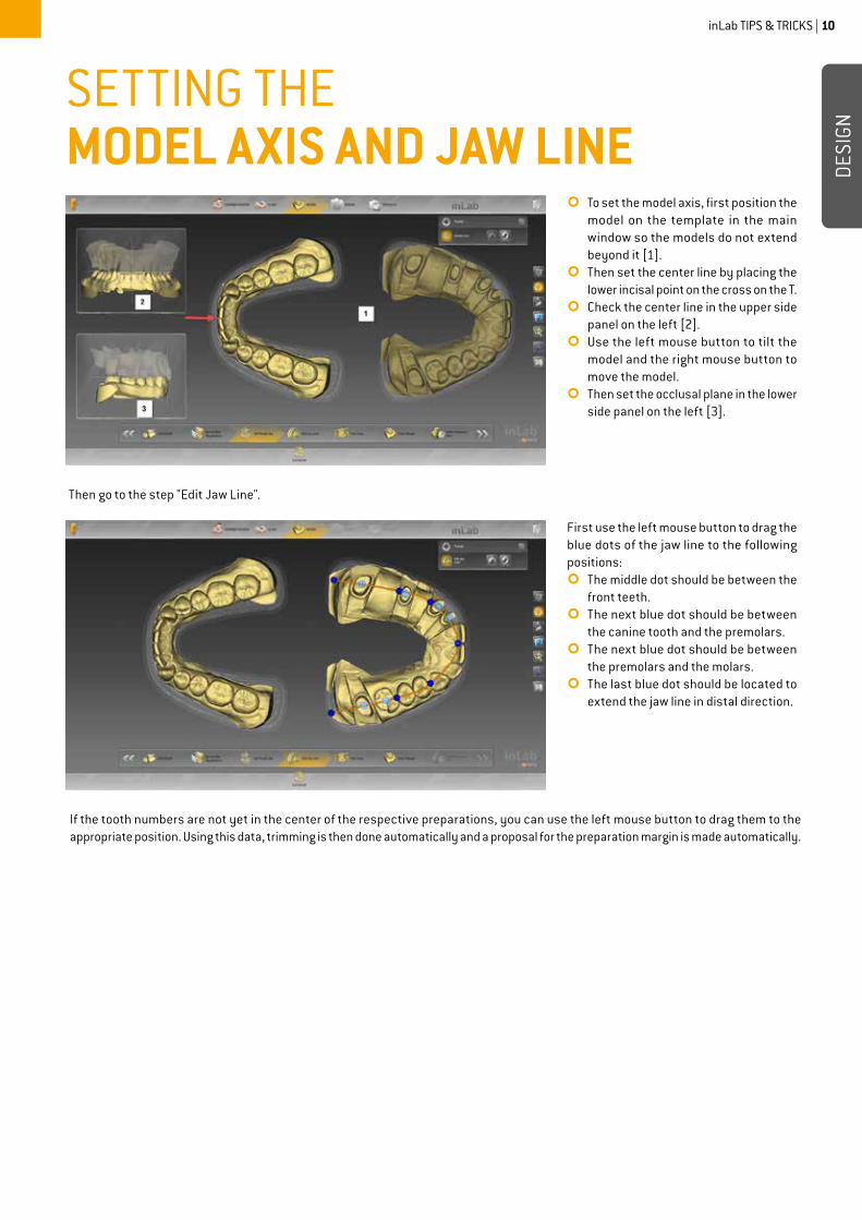
SETTING THE MODEL AXIS AND JAW LINE
Then go to the step "Edit Jaw Line".
If the tooth numbers are not yet in the center of the respective preparations, you can use the left mouse button to drag them to the appropriate position. Using this data, trimming is then done automatically and a proposal for the preparation margin is made automatically.
¢To set the model axis, first position the model on the template in the main window so the models do not extend beyond it [1].
¢Then set the center line by placing the lower incisal point on the cross on the T.
¢Check the center line in the upper side panel on the left [2].
¢Use the left mouse button to tilt the model and the right mouse button to move the model.
¢Then set the occlusal plane in the lower side panel on the left [3].
First use the left mouse button to drag the blue dots of the jaw line to the following positions:¢The middle dot should be between the
front teeth.¢The next blue dot should be between
the canine tooth and the premolars.¢The next blue dot should be between
the premolars and the molars.¢The last blue dot should be located to
extend the jaw line in distal direction.
DESI
GN

TIPS & TRICKS –PRODUCTION
inLab TIPS & TRICKS | 11
inLab TIPS & TRICKS | 12
PROD
UCTI
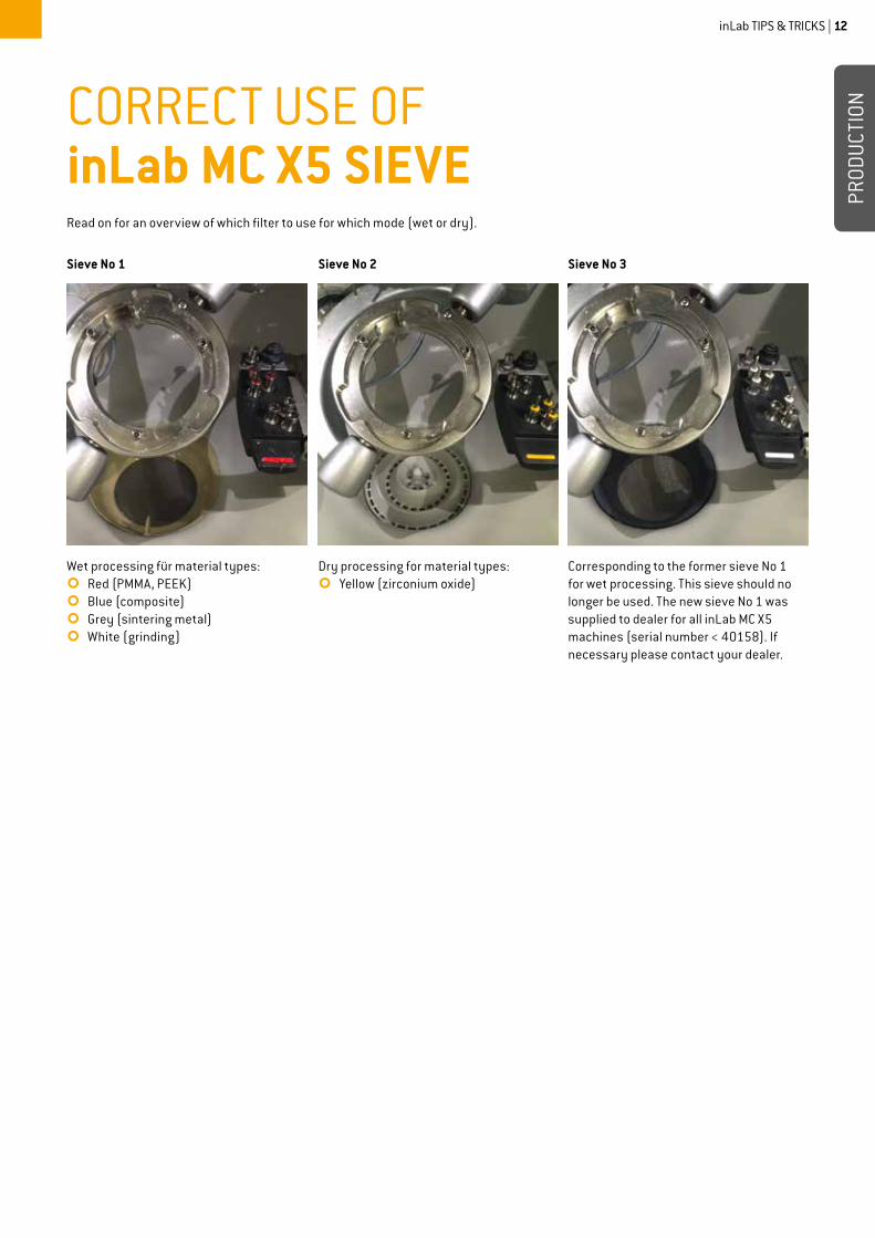
ONCORRECT USE OF inLab MC X5 SIEVERead on for an overview of which filter to use for which mode (wet or dry).
Wet processing für material types: ¢ Red (PMMA, PEEK)¢ Blue (composite)¢ Grey (sintering metal)¢ White (grinding)
Sieve No 1
Corresponding to the former sieve No 1 for wet processing. This sieve should no longer be used. The new sieve No 1 was supplied to dealer for all inLab MC X5 machines (serial number < 40158). If necessary please contact your dealer.
Sieve No 3
Dry processing for material types:¢ Yellow (zirconium oxide)
Sieve No 2

inLab MC X5 – WET OR DRY OPERATION
THE FOLLOWING TIPS ARE FOR OPTIMAL OPERATION OF inLab MC X5:
¢The inLab MC X5 drain hose should be placed as vertical as possible – from the machine to the coolant tank – to prevent remaining coolant from entering the suction system when changing from wet to dry operation.
¢Before every dry processing, the very fine wet processing sieve must be removed from the machine and the insert for dry processing with larger openings should be used to prevent clogging of the sieve.
inLab TIPS & TRICKS | 13
PROD
UCTI
ON

TIPS & TRICKS –SIRONA CONNECT
inLab TIPS & TRICKS | 14

CEREC Ortho INTERFACE WITH SIRONA CONNECT
With the CEREC Omnicam, one of the smallest powder-free video cameras on the market, and the new CEREC Ortho software, precise full jaw scans can be created and sent digitally – for planning and producing orthodontic appliances, for example for Invisalign treatment using aligners. The digital models can also be sent to any orthodontic lab in the Sirona Connect network.
Tip: If you are a registered Sirona Connect lab and also produce orthodontic appliances, you can now indicate this in your Sirona Connect lab profile . Just check "Orthodontic appliances" under My account > Services. By doing so, you indicate that you provide this service. You now can be found not only in the Sirona Connect software, but also in the current CEREC Ortho software.
inLab TIPS & TRICKS | 15
CONN
ECT

inLab DESIGN SERVICE FOR CEREC PRACTICES As of inLab SW 15.0, laboratories can return .dxd files with restorations to the practice via the Sirona Connect Portal in order to import them there into the CEREC software (as of version 4.4) and mill them on a CEREC milling unit.
IT COULDN'T BE SIMPLER:¢The CEREC user scans using the Sirona Connect SW (as of version 4.4) and sends the data set to the laboratory via the Sirona
Connect Portal. Alternatively, he scans with the CEREC software (as of version 4.4) and uses the Sirona Connect button to access the Sirona Connect Portal.
¢The laboratory loads the data into the inLab SW (as of version 15.0) to design the restoration. Note: As an inLab MC X5 user, the laboratory must select the virtual inLab MC XL for the design.
¢The laboratory exports the milling preview in .dxd format and returns it to the CEREC user via the Sirona Connect chat function.¢The CEREC user imports the data set into the CEREC SW and produces the restoration on his own milling unit.
inLab TIPS & TRICKS | 16
CONN
ECT
SCANSirona Connect SW or CEREC Software (as of version 4.4)
Sending of scan data
Sending of restoration data
PRODUCTIONWith CEREC milling unit (as of version CEREC SW 4.4)
DESIGN(as of version inLab SW 15.0)
CEREC PRACTICE LAB
SIRONACONNECT PORTAL