innovation. amplified. - peavey
TRANSCRIPT
Chapter 5
The Ancient Order of the
Mystic Magnetic
Pickup
byHartley Peavey
Innovation. Amplified.
The Ancient Order of the Mystic Magnetic Pickup Interestingly, here in the new millennium there is
still more mystery, BS, and misunderstanding regard-ing guitar and bass pickups than almost any other as-pect of musical instruments. Because pickups seem “mysterious,” many players tend to attribute “super-natural abilities” to what really is a fairly simple device (that can be made in many configurations and from a number of different materials). The basic principles re-main exactly the same as the very first pickups.
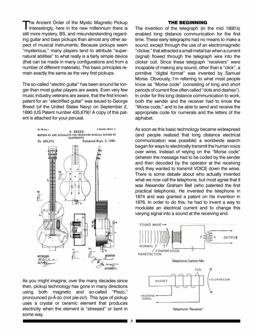
The so-called “electric guitar” has been around far lon-ger than most guitar players are aware. Even very few music industry veterans are aware, that the first known patent for an “electrified guitar” was issued to George Breed (of the United States Navy) on September 2, 1890 (US Patent number 435,679)! A copy of this pat-ent is attached for your perusal.
As you might imagine, over the many decades since then, pickup technology has gone in many directions using both magnetic and so-called “Piezo,” pronounced pi-Á-zo (not pie-zo!). This type of pickup uses a crystal or ceramic element that produces electricity when the element is “stressed” or bent in some way.
THe BeginningThe invention of the telegraph (in the mid 1800’s) enabled long distance communication for the first time. These early telegraphs had no means to make a sound, except through the use of an electromagnetic “clicker,” that attracted a small metal bar when a current (signal) flowed through the telegraph wire into the clicker coil. Since these telegraph “receivers” were incapable of making any sound, other than a “click”, a primitive “digital format” was invented by Samuel Morse. Obviously, I’m referring to what most people know as “Morse code” (consisting of long and short periods of current flow often called “dots and dashes”). In order for this long distance communication to work, both the sender and the receiver had to know the “Morse code,” and to be able to send and receive the appropriate code for numerals and the letters of the alphabet.
As soon as this basic technology became widespread (and people realized that long distance electrical communication was possible) a worldwide search began for ways to electrically transmit the human voice over wires. Instead of relying on the “Morse code” (wherein the message had to be coded by the sender and then decoded by the operator at the receiving end) they wanted to transmit VOICE down the wires. There is some debate about who actually invented what we now call the telephone, but most agree that it was Alexander Graham Bell (who patented the first practical telephone). He invented the telephone in 1874 and was granted a patent on his invention in 1876. In order to do this, he had to invent a way to modulate an electrical current and to change this varying signal into a sound at the receiving end.
22
The Ancient Order of the Mystic Magnetic Pickup
Interestingly, here in the new millennium there is still more mystery, BS, and misunderstanding regarding guitar and bass pickups than almost any other aspect of musical instruments. Because pickups seem “mysterious,” many players tend to attribute “supernatural abilities” to what really is a fairly simple device (that can be made in many configurations and from a number of different materials). The basic principles remain exactly the same as the very first pickups.
The so-called “electric guitar” has been around far longer than most guitar players are aware. Even very few music industry veterans are aware, that the first known patent for an “electrified guitar” was issued to George Breed (of the United States Navy) on September 2, 1890 (US Patent number 435,679)! A copy of this patent is attached for your perusal.
As you might imagine, over the many decades since then, pickup technology has gone in many directions using both magnetic and so-called “Piezo,” pronounced pi-Á-zo (not pie-zo!). This type of pickup uses a crystal or ceramic element that produces electricity when the element is “stressed” or bent in some way.
3
The Beginning
The invention of the telegraph (in the mid 1800’s) enabled long distance communication for the first time. These early telegraphs had no means to make a sound, except through the use of an electromagnetic “clicker,” that attracted a small metal bar when a current (signal) flowed through the telegraph wire into the clicker coil.Since these telegraph “receivers” were incapable of making any sound, other than a “click”, a primitive “digital format” was invented by Samuel Morse. Obviously, I’m referring to what most people know as “Morse code” (consisting of long and short periods of current flow often called “dots and dashes”). In order for this long distance communication to work, both the sender and the receiver had to know the “Morse code,” and to be able to send and receive the appropriate code for numerals and the letters of the alphabet.
As soon as this basic technology became widespread (and people realized that long distance electrical communication was possible) a worldwide search began for ways to electrically transmit the human voice over wires. Instead of relying on the “Morse code” (wherein the message had to be coded by the sender and then decoded by the operator at the receiving end) they wanted to transmit VOICE down the wires. There is some debate about who actually invented what we now call the telephone, but most agree that it was Alexander Graham Bell (who patented the first practical telephone). He invented the telephone in 1874 and was granted a patent on his invention in 1876. In order to do this, he had to invent a way to modulate an electrical current and to change this varying signal into a sound at the receiving end.
Telephone Carbon Mic Telephone “Receiver”
Bell discovered that if he used a flexible diaphragm pressing against a “capsule” of carbon particles, the pressure on the diaphragm would variably compress the carbon granules; thus, causing the current through the connecting wires to vary with the movement of the diaphragm. Essentially, Bell discovered a way of making a “variable resistor” controlled by the movement of a thin diaphragm. Since there were no known amplification devices during that time, Bell discovered a novel way of controlling the flow of electricity at the audio rate by utilizing a diaphragm to vary pressure on the electrically conducting carbon granules. This was the first practical microphone, which led to the telephone. It was understood by the 1880s, that a varying current flow in a coil could move a piece of magnetic material in direct proportion to the amount of current flowing through the coil.
Telephone Carbon Mic
Telephone “Receiver”
Bell discovered that if he used a flexible diaphragm pressing against a “capsule” of carbon particles, the pressure on the diaphragm would variably compress the carbon granules; thus, causing the current through the connecting wires to vary with the movement of the diaphragm. Essentially, Bell discovered a way of making a “variable resistor” controlled by the movement of a thin diaphragm. Since there were no known amplification devices during that time, Bell discovered a novel way of controlling the flow of electricity at the audio rate by utilizing a diaphragm to vary pressure on the electrically conducting carbon granules. This was the first practical microphone, which led to the telephone. It was understood by the 1880s, that a varying current flow in a coil could move a piece of magnetic material in direct proportion to the amount of current flowing through the coil.
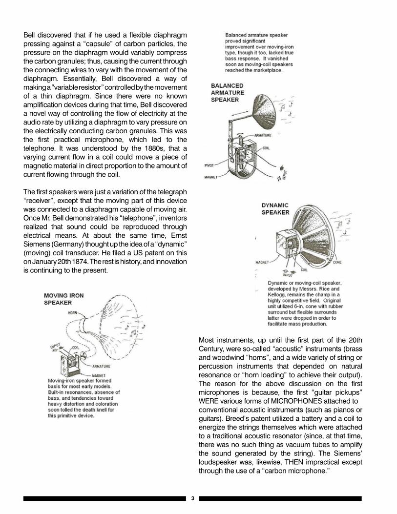
The first speakers were just a variation of the telegraph “receiver”, except that the moving part of this device was connected to a diaphragm capable of moving air. Once Mr. Bell demonstrated his “telephone”, inventors realized that sound could be reproduced through electrical means. At about the same time, Ernst Siemens (Germany) thought up the idea of a “dynamic” (moving) coil transducer. He filed a US patent on this on January 20th 1874. The rest is history, and innovation is continuing to the present.
Most instruments, up until the first part of the 20th Century, were so-called “acoustic” instruments (brass and woodwind “horns”, and a wide variety of string or percussion instruments that depended on natural resonance or “horn loading” to achieve their output). The reason for the above discussion on the first microphones is because, the first “guitar pickups” WERE various forms of MICROPHONES attached toconventional acoustic instruments (such as pianos or guitars). Breed’s patent utilized a battery and a coil to energize the strings themselves which were attached to a traditional acoustic resonator (since, at that time, there was no such thing as vacuum tubes to amplify the sound generated by the string). The Siemens’ loudspeaker was, likewise, THEN impractical except through the use of a “carbon microphone.”
3
4
The first speakers were just a variation of the telegraph “receiver”, except that the moving part of this device was connected to a diaphragm capable of moving air. Once Mr. Bell demonstrated his “telephone”, inventors realized that sound could be reproduced through electrical means. At about the same time, Ernst Siemens (Germany) thought up the idea of a “dynamic” (moving) coil transducer. He filed a US patent on this on January 20th 1874. The rest is history, and innovation is continuing to the present.
Most instruments, up until the first part of the 20th Century, were so-called “acoustic” instruments (brass and woodwind “horns”, and a wide variety of string or percussion instruments that depended on natural resonance or “horn loading” to achieve their output). The reason for the above discussion on the first microphones is because, the first “guitar pickups” WERE various forms of MICROPHONES attached to conventional acoustic instruments (such as pianos or guitars). Breed’s patent utilized a battery and a coil to energize the strings themselves which were attached to a traditional acoustic resonator (since, at that time, there was no such thing as vacuum tubes to amplify the sound generated by the string). The Siemens’ loudspeaker was, likewise, THEN impractical except through the use of a “carbon microphone.”
A Hot Idea
As most people know, Thomas Edison was the first to invent a practical incandescent light bulb. The so-called “Edison bulb” had a Tungsten filament, and the glass bulb itself contained a vacuum that enabled the Tungsten to glow “white hot” (without destroying itself through instant oxidation).
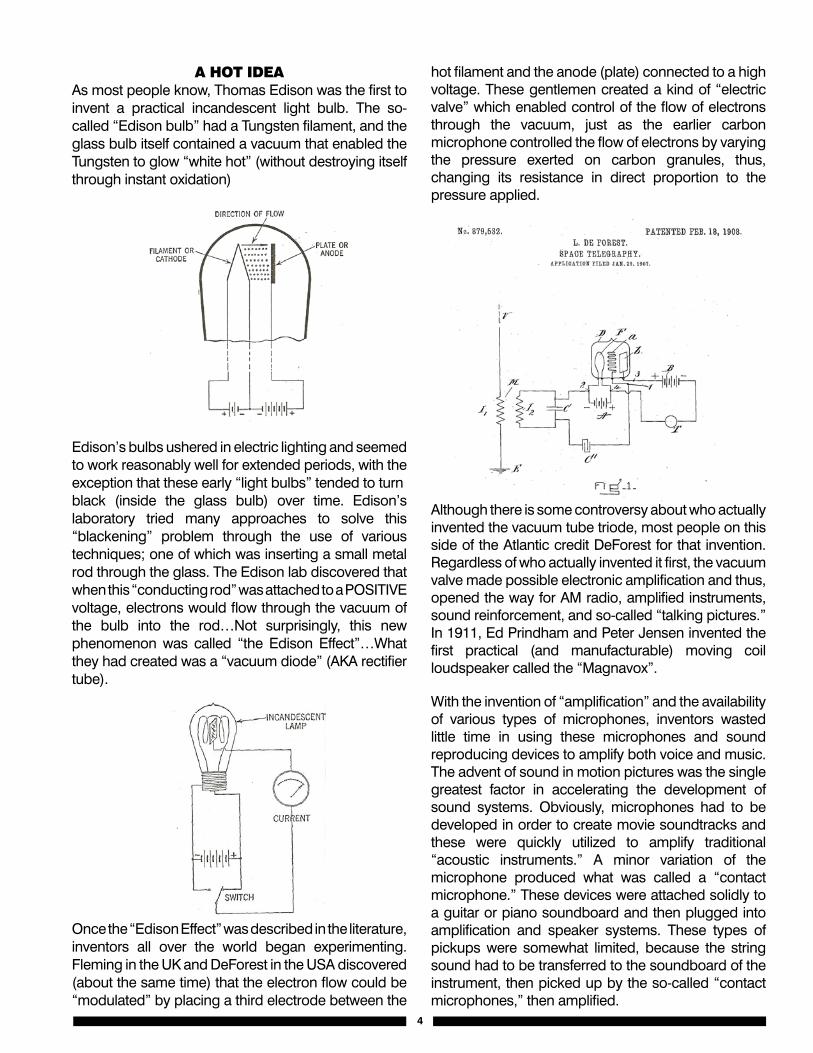
A HOT ideAAs most people know, Thomas Edison was the first to invent a practical incandescent light bulb. The so-called “Edison bulb” had a Tungsten filament, and the glass bulb itself contained a vacuum that enabled the Tungsten to glow “white hot” (without destroying itself through instant oxidation)
Edison’s bulbs ushered in electric lighting and seemed to work reasonably well for extended periods, with the exception that these early “light bulbs” tended to turnblack (inside the glass bulb) over time. Edison’s laboratory tried many approaches to solve this “blackening” problem through the use of various techniques; one of which was inserting a small metal rod through the glass. The Edison lab discovered that when this “conducting rod” was attached to a POSITIVE voltage, electrons would flow through the vacuum of the bulb into the rod…Not surprisingly, this new phenomenon was called “the Edison Effect”…What they had created was a “vacuum diode” (AKA rectifier tube).
Once the “Edison Effect” was described in the literature, inventors all over the world began experimenting. Fleming in the UK and DeForest in the USA discovered (about the same time) that the electron flow could be “modulated” by placing a third electrode between the
hot filament and the anode (plate) connected to a high voltage. These gentlemen created a kind of “electric valve” which enabled control of the flow of electrons through the vacuum, just as the earlier carbon microphone controlled the flow of electrons by varying the pressure exerted on carbon granules, thus, changing its resistance in direct proportion to the pressure applied.
Although there is some controversy about who actually invented the vacuum tube triode, most people on this side of the Atlantic credit DeForest for that invention. Regardless of who actually invented it first, the vacuum valve made possible electronic amplification and thus, opened the way for AM radio, amplified instruments, sound reinforcement, and so-called “talking pictures.” In 1911, Ed Prindham and Peter Jensen invented the first practical (and manufacturable) moving coil loudspeaker called the “Magnavox”.
With the invention of “amplification” and the availability of various types of microphones, inventors wasted little time in using these microphones and sound reproducing devices to amplify both voice and music. The advent of sound in motion pictures was the single greatest factor in accelerating the development of sound systems. Obviously, microphones had to be developed in order to create movie soundtracks and these were quickly utilized to amplify traditional “acoustic instruments.” A minor variation of the microphone produced what was called a “contact microphone.” These devices were attached solidly to a guitar or piano soundboard and then plugged into amplification and speaker systems. These types of pickups were somewhat limited, because the string sound had to be transferred to the soundboard of the instrument, then picked up by the so-called “contact microphones,” then amplified.
4
5
Edison’s bulbs ushered in electric lighting and seemed to work reasonably well for extended periods, with the exception that these early “light bulbs” tended to turn black (inside the glass bulb) over time. Edison’s laboratory tried many approaches to solve this “blackening” problem through the use of various techniques; one of which was inserting a small metal rod through the glass. The Edison lab discovered that when this “conducting rod” was attached to a POSITIVE voltage, electrons would flow through the vacuum of the bulb into the rod…Not surprisingly, this new phenomenon was called “the Edison Effect”…What they had created was a “vacuum diode” (AKA rectifier tube).
Once the “Edison Effect” was described in the literature, inventors all over the world began experimenting. Fleming in the UK and DeForest in the USA discovered (about the same time) that the electron flow could be “modulated” by placing a third electrode between the hot filament and the anode (plate) connected to a high voltage. These gentlemen created a kind of “electric valve” which enabled control of the flow of electrons through the vacuum, just as the earlier carbon microphone controlled the flow of electrons by varying the pressure exerted on carbon granules, thus, changing its resistance in direct proportion to the pressure applied.
6
Although there is some controversy about who actually invented the vacuum tube triode, most people on this side of the Atlantic credit DeForest for that invention.Regardless of who actually invented it first, the vacuum valve made possible electronic amplification and thus, opened the way for AM radio, amplified instruments, sound reinforcement, and so-called “talking pictures.” In 1911, Ed Prindham and Peter Jensen invented the first practical (and manufacturable) moving coil loudspeaker called the “Magnavox”.
With the invention of “amplification” and the availability of various types of microphones, inventors wasted little time in using these microphones and sound reproducing devices to amplify both voice and music. The advent of sound in motion pictures was the single greatest factor in accelerating the development of sound systems. Obviously, microphones had to be developed in order to create movie soundtracks and these were quickly utilized to amplify traditional “acoustic instruments.”A minor variation of the microphone produced what was called a “contact microphone.”These devices were attached solidly to a guitar or piano soundboard and then plugged into amplification and speaker systems. These types of pickups were somewhat limited, because the string sound had to be transferred to the soundboard of the instrument, then picked up by the so-called “contact microphones,” then amplified.
Rickenbacker was one of the first manufacturers to dispense with so-called “contact microphones” and sense the vibrations DIRECTLY from the strings themselves. Many (wrongly) believe the so-called “frying pan” lap steel to be the first “electric” guitar. As we now know, the very first electric guitar (though somewhat impractical) was invented by Mr. Breed some 40 years earlier (1890). Rickenbacker’s guitar was certainly one of the earliest commercial electric guitars utilizing a magnetic pickup, the BASIC principle of which is much the same as the pickups on today’s guitars.
Rickenbacker was one of the first manufacturers to dispense with so-called “contact microphones” and sense the vibrations DIRECTLY from the strings themselves. Many (wrongly) believe the so-called “frying pan” lap steel to be the first “electric” guitar. As we now know, the very first electric guitar (though somewhat impractical) was invented by Mr. Breed some 40 years earlier (1890). Rickenbacker’s guitar was certainly one of the earliest commercial electric guitars utilizing a magnetic pickup, the BASIC principle of which is much the same as the pickups on today’s guitars.
Before getting into any meaningful discussion of guitar and bass pickups, one must understand that there are several ways to generate an electrical signal by sensing the motion of an object (be it a string, a microphone diaphragm, the soundboard of an instrument, or in fact, almost any moving object). As far as our discussion here, we’re primarily interested in the kinds of transducers used on guitars and basses. Please note, that a so-called “transducer” is ANY device that CONVERTS one form of energy into another. A loudspeaker IS a “transducer,” because it converts electrical energy into movement of a cone/diaphragm, thus, producing sound…Conversely, a guitar pickup senses motion of the strings and converts that into electrical energy, thus, it is also a “transducer.”
Almost all electricity is generated by a “magnetic process.” Admittedly, there are other ways to produce electricity, such as the aforementioned Piezo elements that generate electricity when the Piezo element is stressed (such as being bent or twisted).
An example of this type of electricity generation is those “snap action” fire starters or candle lighters that ignite a small gas jet used to light candles or fires
The process is started by pulling a trigger, which “stresses” a Piezo element, thus, causing rapid generation of electricity, which is fed to a small “spark gap” in the nozzle of the gas outlet. Some cigarette lighters use the same “Piezo effect” (ditto some ignition systems in small gas engines).
In addition to the Piezo effect briefly described above, electricity can be generated by solar energy or chemically in a battery or in a fuel cell. This type o electrical “generator” is only capable of producing so-called “direct current” and is not really useful for any kind of sensing device (pickup) which is the topic of the present discussion. There are also various forms of generators utilized to produce extremely high voltages, which are also totally outside the realm and scope of this paper.
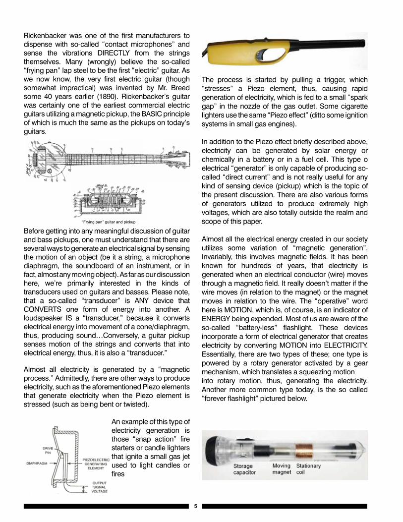
Almost all the electrical energy created in our society utilizes some variation of “magnetic generation”. Invariably, this involves magnetic fields. It has been known for hundreds of years, that electricity is generated when an electrical conductor (wire) moves through a magnetic field. It really doesn’t matter if the wire moves (in relation to the magnet) or the magnet moves in relation to the wire. The “operative” word here is MOTION, which is, of course, is an indicator of ENERGY being expended. Most of us are aware of the so-called “battery-less” flashlight. These devices incorporate a form of electrical generator that creates electricity by converting MOTION into ELECTRICITY. Essentially, there are two types of these; one type is powered by a rotary generator activated by a gear mechanism, which translates a squeezing motioninto rotary motion, thus, generating the electricity. Another more common type today, is the so called “forever flashlight” pictured below.
5
7
“Frying pan” guitar and pickup
Before getting into any meaningful discussion of guitar and bass pickups, one must understand that there are several ways to generate an electrical signal by sensing the motion of an object (be it a string, a microphone diaphragm, the soundboard of an instrument, or in fact, almost any moving object). As far as our discussion here, we’re primarily interested in the kinds of transducers used on guitars and basses. Please note, that a so-called “transducer” is ANY device that CONVERTS one form of energy into another. A loudspeaker IS a “transducer,” because it converts electrical energy into movement of a cone/diaphragm, thus, producing sound…Conversely, a guitar pickup senses motion of the strings and converts that into electrical energy, thus, it is also a “transducer.”
Almost all electricity is generated by a “magnetic process.” Admittedly, there are other ways to produce electricity, such as the aforementioned Piezo elements that generate electricity when the Piezo element is stressed (such as being bent or twisted).
Piezo Mic Pickup
An example of this type of electricity generation is those “snap action” fire starters or candle lighters that ignite a small gas jet used to light candles or fires.
8
The process is started by pulling a trigger, which “stresses” a Piezo element, thus, causing rapid generation of electricity, which is fed to a small “spark gap” in the nozzle of the gas outlet. Some cigarette lighters use the same “Piezo effect” (ditto some ignition systems in small gas engines).
In addition to the Piezo effect briefly described above, electricity can be generated by solar energy or chemically in a battery or in a fuel cell. This type of electrical “generator” is only capable of producing so-called “direct current” and is not really useful for any kind of sensing device (pickup) which is the topic of the present discussion. There are also various forms of generators utilized to produce extremely high voltages, which are also totally outside the realm and scope of this paper.
Almost all the electrical energy created in our society utilizes some variation of “magnetic generation”. Invariably, this involves magnetic fields. It has been known for hundreds of years, that electricity is generated when an electrical conductor (wire) moves through a magnetic field. It really doesn’t matter if the wire moves (in relation to the magnet) or the magnet moves in relation to the wire. The “operative” word here is MOTION, which is, of course, is an indicator of ENERGY being expended.
Most of us are aware of the so-called “battery-less” flashlight. These devices incorporate a form of electrical generator that creates electricity by converting MOTION into ELECTRICITY. Essentially, there are two types of these; one type is powered by a rotary generator activated by a gear mechanism, which translates a squeezing motion into rotary motion, thus, generating the electricity. Another more common type today, is the so called “forever flashlight” pictured below.
This unit consists of a coil of wire, a very strong magnet that is free to “slide” inside the coil, and a small energy storage device called a CAPACITOR. This unit generates electricity when the operator rapidly “shakes” the unit so that the moving magnet slides through the internal coil of wire. Because the magnet slides through a coil of wire with multiple turns, the magnetic field changes at the same rate as the motion (energy) of the magnet. As the lines of magnetic force “cut” thorough the coil, electricity is generated. Simply put, this type flashlight translates motion into electrical energy by moving a magnetic field through the coil. It would work just as well if the coil moved and the magnet was stationary, but this would cause problems in terminating the coil’s output leads.
Permanent magnets have been known to science for many centuries. The first magnets were called “lodestones.” These were naturally occurring pieces of iron that had become magnetized in their environment. These types of materials were the primary working elements of early compasses. Most of us know that the Earth itself has an easily detectable magnetic field, and that utilizing a permanent magnet mounted to some kind of “pivoting arm” constitutes a compass (because the magnetized indicator will always “point” in the direction of the Earth’s North and South poles). Magnets must have “polarity” in order to be magnets. Traditionally, the “poles” of a magnet have been called either North (N) or South (S). Magnetic “poles” (as with many things in nature) are attracted to the “opposite polarity.” In other words, a magnet’s North pole will be “ATTRACTED” to another magnet’s South pole while, the second magnet’s North pole is REPELLED from the first magnet’s North pole. Simply put: “OPPOSITE” polarities ATTRACT, like polarities REPELL. This
attraction/repulsion is the basic principle of operation of electric motors, loudspeakers, and many other magnetic devices that we use and encounter in modern life.
By definition, a magnet has two opposite poles. Extending from all magnets is a magnetic “force,” also known as a “magnetic field.” Generally, this field radiates from the magnet’s North pole and its South pole as illustrated above. This magnetic “field” is also called “flux” or magnetic “lines of force.” The field extends from one pole to the other as illustrated above.
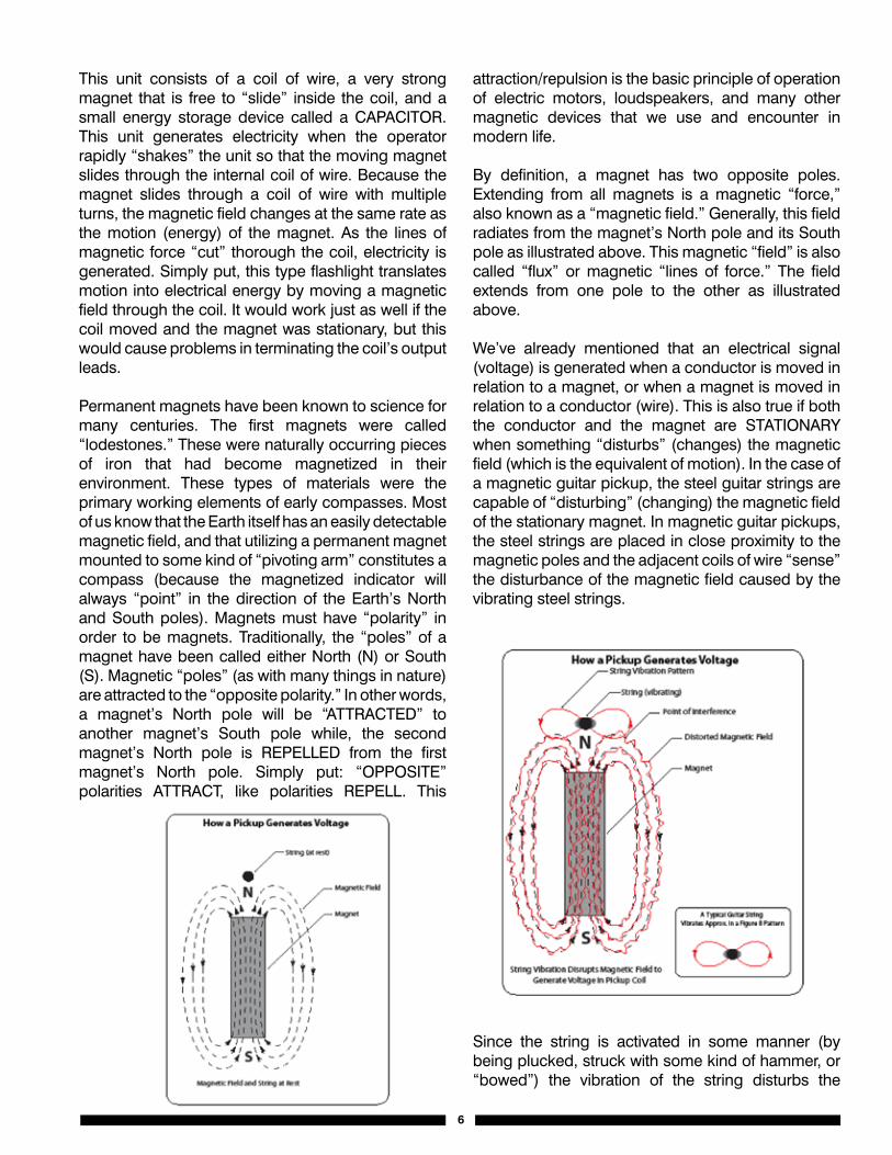
We’ve already mentioned that an electrical signal (voltage) is generated when a conductor is moved in relation to a magnet, or when a magnet is moved in relation to a conductor (wire). This is also true if both the conductor and the magnet are STATIONARY when something “disturbs” (changes) the magnetic field (which is the equivalent of motion). In the case of a magnetic guitar pickup, the steel guitar strings are capable of “disturbing” (changing) the magnetic field of the stationary magnet. In magnetic guitar pickups, the steel strings are placed in close proximity to the magnetic poles and the adjacent coils of wire “sense” the disturbance of the magnetic field caused by the vibrating steel strings.
Since the string is activated in some manner (by being plucked, struck with some kind of hammer, or “bowed”) the vibration of the string disturbs the
6
7
magnetic field at whatever frequency the string is tuned to. It’s important to note, that the energy imparted to the string causes the string to move in a somewhat predictable manner and the motion of the steel string causes the magnetic field to vary which, in turn, induces a signal into the adjacent coil of wire at the SAME RATE that the STRING is VIBRATING.
The energy imparted to the string by the player is converted into an electric signal by the steel string’s ability to change the pickup’s “MAGNETIC FIELD.”
As stated above, any device that changes one form of energy (motion) into another form of energy (electricity) is called a “transducer.” A guitar pickup changes motion into electricity. While at the opposite end of the “audio chain,” a loudspeaker changes electrical energy into motion (sound) thus, completing the process that we recognize as “electric guitar sound.” It should be noted, that so-called “electric guitars” must have strings made of materials that are capable of causing a magnetic influence on the pickup’s magnetic field. Generally, nickel and steel are used for electric guitar strings. Nylon and bronze are also used
for strings; however, these tend to be utilized on guitars with “non-magnetic” pickups, such as the Piezo sensors described above or some kind of “contact microphone” that senses changes in pressure either under the “bridge” or the soundboard of the instrument.
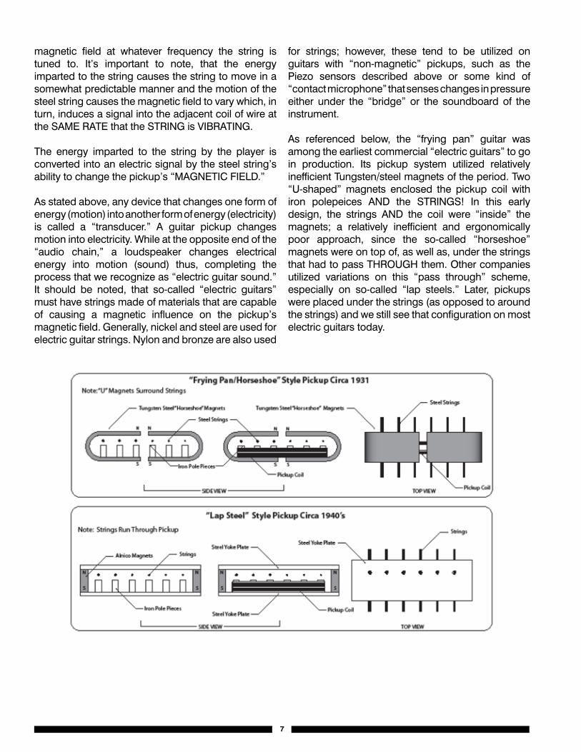
As referenced below, the “frying pan” guitar was among the earliest commercial “electric guitars” to go in production. Its pickup system utilized relatively inefficient Tungsten/steel magnets of the period. Two “U-shaped” magnets enclosed the pickup coil with iron polepeices AND the STRINGS! In this early design, the strings AND the coil were “inside” the magnets; a relatively inefficient and ergonomically poor approach, since the so-called “horseshoe” magnets were on top of, as well as, under the strings that had to pass THROUGH them. Other companies utilized variations on this “pass through” scheme, especially on so-called “lap steels.” Later, pickups were placed under the strings (as opposed to around the strings) and we still see that configuration on most electric guitars today.
8
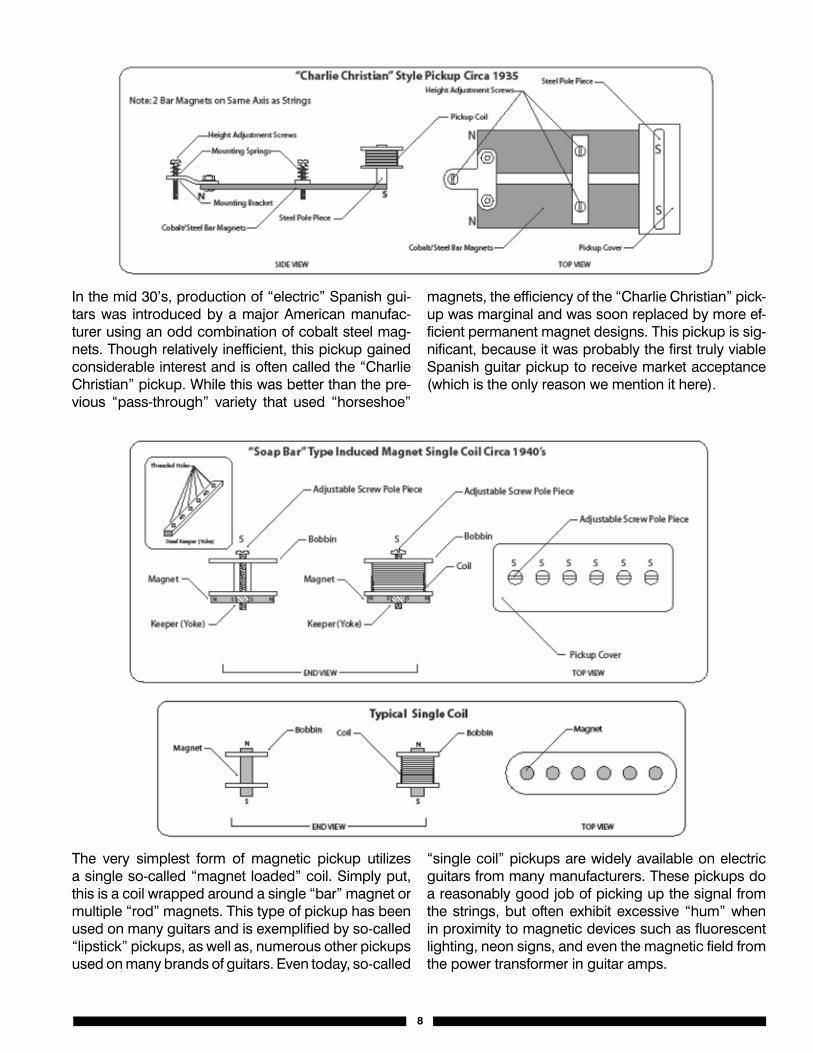
In the mid 30’s, production of “electric” Spanish gui-tars was introduced by a major American manufac-turer using an odd combination of cobalt steel mag-nets. Though relatively inefficient, this pickup gained considerable interest and is often called the “Charlie Christian” pickup. While this was better than the pre-vious “pass-through” variety that used “horseshoe”
magnets, the efficiency of the “Charlie Christian” pick-up was marginal and was soon replaced by more ef-ficient permanent magnet designs. This pickup is sig-nificant, because it was probably the first truly viable Spanish guitar pickup to receive market acceptance (which is the only reason we mention it here).
The very simplest form of magnetic pickup utilizes a single so-called “magnet loaded” coil. Simply put, this is a coil wrapped around a single “bar” magnet or multiple “rod” magnets. This type of pickup has been used on many guitars and is exemplified by so-called “lipstick” pickups, as well as, numerous other pickups used on many brands of guitars. Even today, so-called
“single coil” pickups are widely available on electric guitars from many manufacturers. These pickups do a reasonably good job of picking up the signal from the strings, but often exhibit excessive “hum” when in proximity to magnetic devices such as fluorescent lighting, neon signs, and even the magnetic field from the power transformer in guitar amps.
9
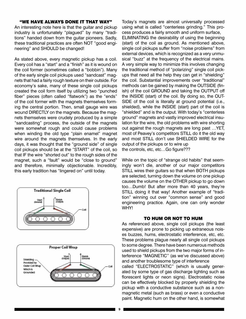
“We HAve AlWAys dOne iT THAT WAy”An interesting note here is that the guitar and pickup industry is unfortunately “plagued” by many “tradi-tions” handed down from the guitar pioneers. Sadly, these traditional practices are often NOT “good engi-neering” and SHOULD be changed!
As stated above, every magnetic pickup has a coil. Every coil has a “start” and a “finish” as it is wound on the coil former (sometimes called a “bobbin”). Many of the early single coil pickups used “sandcast” mag-nets that had a fairly rough texture on their outside. For economy’s sake, many of these single coil pickups created the coil form itself by utilizing two “punched fiber” pieces (often called “flatwork”) as the “ends” of the coil former with the magnets themselves form-ing the central portion. Then, small gauge wire was wound DIRECTLY on the magnets. Because the mag-nets themselves were crudely produced by a simple “sandcasting” process, the outside of the magnets were somewhat rough and could cause problems when winding the old type “plain enamel” magnet wire around the magnets themselves. In the early days, it was thought that the “ground side” of single coil pickups should be at the “START” of the coil, so that IF the wire “shorted out” to the rough sides of the magnet, such a “fault” would be “close to ground” and therefore, minimally objectionable. Incredibly, this early tradition has “lingered on” until today.
Today’s magnets are almost universally processed using what is called “centerless grinding.” This pro-cess produces a fairly smooth and uniform surface,ELIMINATING the desirability of using the beginning (start) of the coil as ground. As mentioned above, single coil pickups suffer from “noise problems” from external devices, which is recognized as a very unmu-sical “buzz” at the frequency of the electrical mains. A very simple way to minimize this involves changing the traditional method of “polarizing” single coil pick-ups that need all the help they can get in “shielding” the coil. Substantial improvements over “traditional” methods can be gained by making the OUTSIDE (fin-ish) of the coil GROUND and taking the OUTPUT off the INSIDE (start) of the coil. By doing so, the OUT-SIDE of the coil is literally at ground potential (i.e., shielded), while the INSIDE (start) part of the coil is “shielded” and is the output. With today’s “centerless ground” magnets and vastly improved electrical insu-lation for the wire, the old problems with wire shorting out against the rough magnets are long past …YET, most of Peavey’s competitors STILL do it the old way and most STILL don’t use SHIELDED WIRE for the output of the pickups or to wire upthe controls, etc, etc…Go figure???
While on the topic of “strange old habits” that seem-ingly won’t die, another of our major competitors STILL wires their guitars so that when BOTH pickups are selected, turning down the volume on one pickup causes the volume on the OTHER pickup to go down too…Dumb! But after more than 40 years, they’re STILL doing it that way! Another example of “tradi-tion” winning out over “common sense” and good engineering practice. Again, one can only wonder WHY!
TO HuM Or nOT TO HuMAs referenced above, single coil pickups (the least expensive) are prone to picking up extraneous nois-es buzzes, hums, electrostatic interference, etc, etc. These problems plague nearly all single coil pickups to some degree. There have been numerous methods used to shield pickups from the two major forms of in-terference “MAGNETIC” (as we’ve discussed above) and another troublesome type of interferencecalled “ELECTROSTATIC” (which is usually gener-ated by some type of gas discharge lighting such as florescent lights or neon signs). Electrostatic noise can be effectively blocked by properly shielding the pickup with a conductive substance such as a non-magnetic metal (such as brass) or even a conductive paint. Magnetic hum on the other hand, is somewhat
10
more difficult to prevent. One of the best methods yet found, is to use very low impedance pickups (having as little as one turn) which unfortunately require use of a matching transformer (which in many cases defeats the advantages of low impedance pickups both from a technical and a cost standpoint).
Early guitar amplifiers were relatively low powered, used inefficient speakers, and featured just enough gain to allow the guitar to function. Though noise, hum, and buzz were problems; these negative effects were not big problems. Later, as music demanded louder performances, amplifiers became larger, more powerful, and had more gain. Guitar builders were searching for ways to make their product better and they learned about “hum canceling” techniques uti-lized for decades by the telephone companies; who used so-called “balanced coils” to cancel (buck) hum induced into their telephone lines by adjacent electri-cal power lines. The so-called “hum canceling” guitar pickup was introduced in a major way in the 1950s. Incredibly, most players (and even most dealers) don’t understand the basic principles of the so-called “hum canceling” pickup. Balanced lines have been used in the telephone industry (and in the broadcast and recording industry) since their beginnings. The same techniques were applied to guitar pickups and this is why “hum canceling” pickups generally have at least two coils. These coils are usually arranged so that each coil is directly out of phase (180°) from the other.
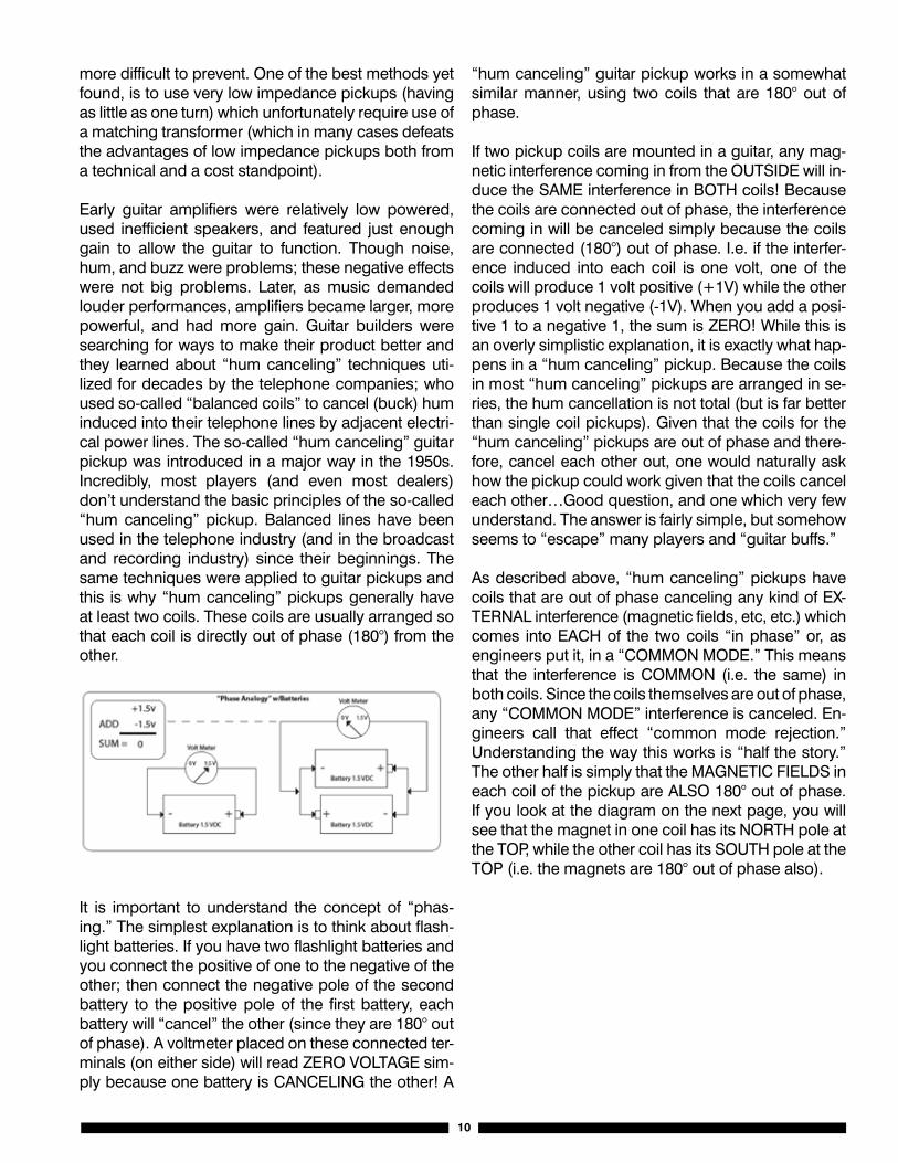
It is important to understand the concept of “phas-ing.” The simplest explanation is to think about flash-light batteries. If you have two flashlight batteries and you connect the positive of one to the negative of the other; then connect the negative pole of the second battery to the positive pole of the first battery, each battery will “cancel” the other (since they are 180° out of phase). A voltmeter placed on these connected ter-minals (on either side) will read ZERO VOLTAGE sim-ply because one battery is CANCELING the other! A
“hum canceling” guitar pickup works in a somewhat similar manner, using two coils that are 180° out of phase.
If two pickup coils are mounted in a guitar, any mag-netic interference coming in from the OUTSIDE will in-duce the SAME interference in BOTH coils! Because the coils are connected out of phase, the interference coming in will be canceled simply because the coils are connected (180°) out of phase. I.e. if the interfer-ence induced into each coil is one volt, one of the coils will produce 1 volt positive (+1V) while the other produces 1 volt negative (-1V). When you add a posi-tive 1 to a negative 1, the sum is ZERO! While this is an overly simplistic explanation, it is exactly what hap-pens in a “hum canceling” pickup. Because the coils in most “hum canceling” pickups are arranged in se-ries, the hum cancellation is not total (but is far better than single coil pickups). Given that the coils for the “hum canceling” pickups are out of phase and there-fore, cancel each other out, one would naturally ask how the pickup could work given that the coils cancel each other…Good question, and one which very few understand. The answer is fairly simple, but somehow seems to “escape” many players and “guitar buffs.”
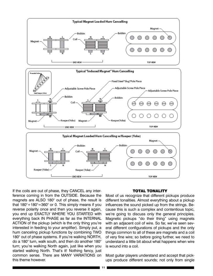
As described above, “hum canceling” pickups have coils that are out of phase canceling any kind of EX-TERNAL interference (magnetic fields, etc, etc.) which comes into EACH of the two coils “in phase” or, as engineers put it, in a “COMMON MODE.” This means that the interference is COMMON (i.e. the same) in both coils. Since the coils themselves are out of phase, any “COMMON MODE” interference is canceled. En-gineers call that effect “common mode rejection.” Understanding the way this works is “half the story.” The other half is simply that the MAGNETIC FIELDS in each coil of the pickup are ALSO 180° out of phase. If you look at the diagram on the next page, you will see that the magnet in one coil has its NORTH pole at the TOP, while the other coil has its SOUTH pole at the TOP (i.e. the magnets are 180° out of phase also).
11
If the coils are out of phase, they CANCEL any inter-ference coming in from the OUTSIDE. Because the magnets are ALSO 180° out of phase, the result is that 180°+180°=360° or 0. This simply means if you reverse polarity once and then you reverse it again, you end up EXACTLY WHERE YOU STARTED with everything back IN PHASE as far as the INTERNAL ACTION of the pickup (which is the only thing you’re interested in feeding to your amplifier). Simply put, a hum canceling pickup functions by combining TWO 180° out of phase systems. If you’re walking NORTH, do a 180° turn, walk south, and then do another 180° turn; you’re walking North again, just like when you started walking North. That’s it! Nothing fancy, just common sense. There are MANY VARIATIONS on this theme however.
TOTAl TOnAliTyMost of us recognize that different pickups produce different tonalities. Almost everything about a pickup influences the sound picked up from the strings. Be-cause this is such a complex and contentious topic, we’re going to discuss only the general principles. Magnetic pickups “do their thing” using magnets with an adjacent coil of wire. So far, we’ve seen sev-eral different configurations of pickups and the only things common to all of these are magnets and a coil of very fine wire; so before going further, we need to understand a little bit about what happens when wire is wound into a coil.
Most guitar players understand and accept that pick-ups produce different sounds; not only from single
12
coil and dual coil (hum canceling) but that the sound also varies within these categories based on a num-ber of factors. A most obvious factor is that a single coil “senses” the string motion at one point (where the pickup is located). It’s equally obvious (but not gen-erally recognized) that a dual coil pickup senses the vibration of the string at TWO locations on the string; thus, contributing to the significantly different sound of a hum canceling (dual coil) pickup from the tonality of a single coil pickup.
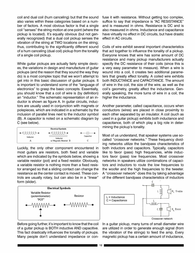
While guitar pickups are actually fairly simple devic-es, the variations in design and manufacture of guitar pickups (and the reason that they sound the way they do) is a most complex topic that we won’t attempt to get into in this basic discussion of guitar pickups. It is important to understand some of the “language of electronics” to grasp the basic concepts. Essentially, you should know that a coil of wire is (by definition) an “inductor.” The schematic representation of an in-ductor is shown as figure A. In guitar circuits, induc-tors are usually used in conjunction with magnets or polepieces, which are indicated in a schematic by the inclusion of parallel lines next to the inductor symbol (B). A capacitor is noted on a schematic diagram by C (see below).
Luckily, the only other component encountered in most guitars are resistors, both fixed and variable which are indicated by the symbols below, showing a variable resistor (pot) and a fixed resistor. Obviously, a variable resistor is nothing more than a fixed resis-tor arranged so that a sliding contact can change the resistance as the center contact is moved. These con-trols are usually rotary, but can also be in a “linear” form (slider).
Before going further, it’s important to know that the coil of a guitar pickup is BOTH inductive AND capacitive. This fact drastically influences the tonality of pickups. Many people don’t understand impedance or con-
fuse it with resistance. Without getting too complex, suffice to say that impedance is “AC RESISTANCE” and is measured in ohms. Resistance is DC and is also measured in ohms. Inductance and capacitance have virtually no effect in DC circuits, but have drastic effect in AC circuits.
Coils of wire exhibit several important characteristics that act together to influence the tonality of a pickup. Everyone knows that wire has some amount of DC resistance and many pickup manufacturers actually specify the DC resistance of their coils (since this is a very easy parameter to measure). When a wire is wound into a coil, it creates two additional parame-ters that greatly effect tonality. A coiled wire exhibits both INDUCTANCE and CAPACITANCE. The amount of wire in the coil, the size of the wire, as well as the coil’s geometry, greatly affect the inductance. Gen-erally speaking, the more turns of wire in a coil, the higher the inductance.
Another parameter, called capacitance, occurs when conductors (wires) are placed in close proximity to each other separated by an insulator. A coil (such as used in a guitar pickup) exhibits both inductance and capacitance, both of which play a big role in deter-mining the pickup’s tonality.
Most of us understand, that speaker systems use so-called “crossover networks.” These frequency divid-ing networks utilize the bandpass characteristics of both inductors and capacitors. Typically, capacitors like to favor (pass) high frequencies, while induc-tors favor (pass) low frequencies. Most crossover networks in speakers utilize combinations of capaci-tors and inductors to route the low frequencies to the woofer and the high frequencies to the tweeter. A “crossover network” does this by taking advantage of the different bandpass characteristics of inductors and capacitors.
In a guitar pickup, many turns of small diameter wire are utilized in order to generate enough signal (from the vibration of the strings) to feed the amp. Every magnetic pickup has a certain amount of inductance,
13
which is generally a “series” type phenomenon. Be-cause the coil has a number of conductors wound together, separated by the insulation on the wire, the coil also has some amount of capacitance (which is a parallel phenomenon).
As in a crossover network, the inductance and the capacitance work together to shape the frequency response (bandpass) of the pickup. Inductors like to pass lows, but not highs. Most pickups tend to have some amount of high frequency degradation (rol-loff) from its own inductance. The more inductance (turns of wire) the more high frequency loss. At the same time, the pickup coil’s capacitance also tends to “shunt” (rolloff) high frequencies. Most players un-derstand that if you put more turns of wire on a pickup bobbin, you will get more output, but lose more high end. The reason for this, is that more turns simultane-ously gives you HIGHER INDUCTANCE AND HIGHER CAPACITANCE (both of which tend to roll off the high end).
Inductance is greatly affected by the physical struc-ture of the pickup and adjacent magnetic metals, polepeices, etc, etc. This is a major reason that pick-up designers have come up with so many different configurations of magnetic structures.
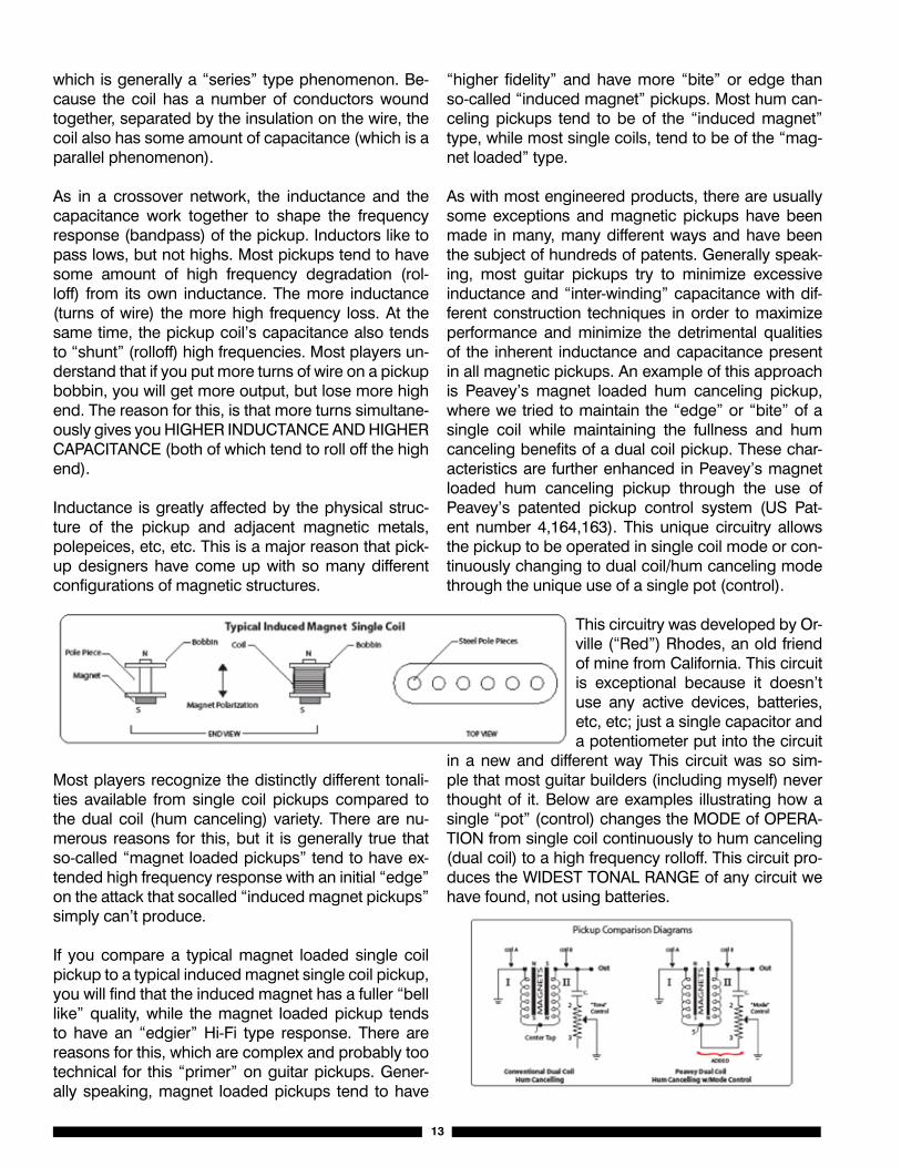
Most players recognize the distinctly different tonali-ties available from single coil pickups compared to the dual coil (hum canceling) variety. There are nu-merous reasons for this, but it is generally true that so-called “magnet loaded pickups” tend to have ex-tended high frequency response with an initial “edge” on the attack that socalled “induced magnet pickups” simply can’t produce.
If you compare a typical magnet loaded single coil pickup to a typical induced magnet single coil pickup, you will find that the induced magnet has a fuller “bell like” quality, while the magnet loaded pickup tends to have an “edgier” Hi-Fi type response. There are reasons for this, which are complex and probably too technical for this “primer” on guitar pickups. Gener-ally speaking, magnet loaded pickups tend to have
“higher fidelity” and have more “bite” or edge than so-called “induced magnet” pickups. Most hum can-celing pickups tend to be of the “induced magnet” type, while most single coils, tend to be of the “mag-net loaded” type.
As with most engineered products, there are usually some exceptions and magnetic pickups have been made in many, many different ways and have been the subject of hundreds of patents. Generally speak-ing, most guitar pickups try to minimize excessive inductance and “inter-winding” capacitance with dif-ferent construction techniques in order to maximize performance and minimize the detrimental qualities of the inherent inductance and capacitance present in all magnetic pickups. An example of this approach is Peavey’s magnet loaded hum canceling pickup, where we tried to maintain the “edge” or “bite” of a single coil while maintaining the fullness and hum canceling benefits of a dual coil pickup. These char-acteristics are further enhanced in Peavey’s magnet loaded hum canceling pickup through the use of Peavey’s patented pickup control system (US Pat-ent number 4,164,163). This unique circuitry allows the pickup to be operated in single coil mode or con-tinuously changing to dual coil/hum canceling mode through the unique use of a single pot (control).
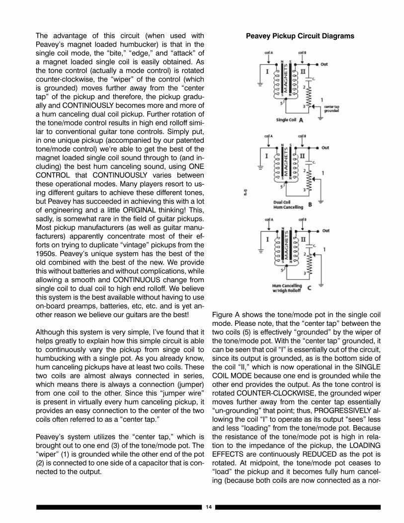
This circuitry was developed by Or-ville (“Red”) Rhodes, an old friend of mine from California. This circuit is exceptional because it doesn’t use any active devices, batteries, etc, etc; just a single capacitor and a potentiometer put into the circuit
in a new and different way This circuit was so sim-ple that most guitar builders (including myself) never thought of it. Below are examples illustrating how a single “pot” (control) changes the MODE of OPERA-TION from single coil continuously to hum canceling (dual coil) to a high frequency rolloff. This circuit pro-duces the WIDEST TONAL RANGE of any circuit we have found, not using batteries.
14
The advantage of this circuit (when used with Peavey’s magnet loaded humbucker) is that in the single coil mode, the “bite,” “edge,” and “attack” of a magnet loaded single coil is easily obtained. As the tone control (actually a mode control) is rotated counter-clockwise, the “wiper” of the control (which is grounded) moves further away from the “center tap” of the pickup and therefore, the pickup gradu-ally and CONTINIOUSLY becomes more and more of a hum canceling dual coil pickup. Further rotation of the tone/mode control results in high end rolloff simi-lar to conventional guitar tone controls. Simply put, in one unique pickup (accompanied by our patented tone/mode control) we’re able to get the best of the magnet loaded single coil sound through to (and in-cluding) the best hum canceling sound, using ONE CONTROL that CONTINUOUSLY varies between these operational modes. Many players resort to us-ing different guitars to achieve these different tones, but Peavey has succeeded in achieving this with a lot of engineering and a little ORIGINAL thinking! This, sadly, is somewhat rare in the field of guitar pickups. Most pickup manufacturers (as well as guitar manu-facturers) apparently concentrate most of their ef-forts on trying to duplicate “vintage” pickups from the 1950s. Peavey’s unique system has the best of the old combined with the best of the new. We provide this without batteries and without complications, while allowing a smooth and CONTINUOUS change from single coil to dual coil to high end rolloff. We believe this system is the best available without having to use on-board preamps, batteries, etc, etc. and is yet an-other reason we believe our guitars are the best!
Although this system is very simple, I’ve found that it helps greatly to explain how this simple circuit is able to continuously vary the pickup from singe coil to humbucking with a single pot. As you already know, hum canceling pickups have at least two coils. These two coils are almost always connected in series, which means there is always a connection (jumper) from one coil to the other. Since this “jumper wire” is present in virtually every hum canceling pickup, it provides an easy connection to the center of the two coils often referred to as a “center tap.”
Peavey’s system utilizes the “center tap,” which is brought out to one end (3) of the tone/mode pot. The “wiper” (1) is grounded while the other end of the pot (2) is connected to one side of a capacitor that is con-nected to the output.
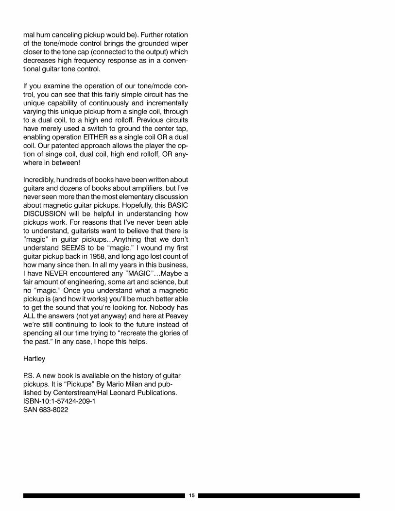
Figure A shows the tone/mode pot in the single coil mode. Please note, that the “center tap” between the two coils (5) is effectively “grounded” by the wiper of the tone/mode pot. With the “center tap” grounded, it can be seen that coil “I” is essentially out of the circuit, since its output is grounded, as is the bottom side of the coil “II,” which is now operational in the SINGLE COIL MODE because one end is grounded while the other end provides the output. As the tone control is rotated COUNTER-CLOCKWISE, the grounded wiper moves further away from the center tap essentially “un-grounding” that point; thus, PROGRESSIVELY al-lowing the coil “I” to operate as its output “sees” less and less “loading” from the tone/mode pot. Because the resistance of the tone/mode pot is high in rela-tion to the impedance of the pickup, the LOADING EFFECTS are continuously REDUCED as the pot is rotated. At midpoint, the tone/mode pot ceases to “load” the pickup and it becomes fully hum cancel-ing (because both coils are now connected as a nor-
Peavey Pickup Circuit Diagrams
15
mal hum canceling pickup would be). Further rotation of the tone/mode control brings the grounded wiper closer to the tone cap (connected to the output) which decreases high frequency response as in a conven-tional guitar tone control.
If you examine the operation of our tone/mode con-trol, you can see that this fairly simple circuit has the unique capability of continuously and incrementally varying this unique pickup from a single coil, through to a dual coil, to a high end rolloff. Previous circuits have merely used a switch to ground the center tap, enabling operation EITHER as a single coil OR a dual coil. Our patented approach allows the player the op-tion of singe coil, dual coil, high end rolloff, OR any-where in between!
Incredibly, hundreds of books have been written about guitars and dozens of books about amplifiers, but I’ve never seen more than the most elementary discussion about magnetic guitar pickups. Hopefully, this BASIC DISCUSSION will be helpful in understanding how pickups work. For reasons that I’ve never been able to understand, guitarists want to believe that there is “magic” in guitar pickups…Anything that we don’t understand SEEMS to be “magic.” I wound my first guitar pickup back in 1958, and long ago lost count of how many since then. In all my years in this business, I have NEVER encountered any “MAGIC”…Maybe a fair amount of engineering, some art and science, but no “magic.” Once you understand what a magnetic pickup is (and how it works) you’ll be much better able to get the sound that you’re looking for. Nobody has ALL the answers (not yet anyway) and here at Peavey we’re still continuing to look to the future instead of spending all our time trying to “recreate the glories of the past.” In any case, I hope this helps.
Hartley
P.S. A new book is available on the history of guitar pickups. It is “Pickups” By Mario Milan and pub-lished by Centerstream/Hal Leonard Publications.ISBN-10:1-57424-209-1SAN 683-8022

Innovation. Amplified.
Peavey Electronics Corporation • 5022 Hartley Peavey Drive • Meridian, MS 39305Phone: (601) 483-5365 • Fax: (601) 486-1278 • www.peavey.com • ©2006 Printed in the U.S.A.