innovations in equipment erection of … in equipment erection of prototype fast breeder reactor...
TRANSCRIPT

INNOVATIONS IN EQUIPMENT
ERECTION OF PROTOTYPE FAST
BREEDER REACTOR (PFBR)
S.Sreekanth, Prabhat Kumar
Bharatiya Nabhikiya Vidyut Nigam Limited (BHAVINI),
Department of Atomic Energy, INDIA
Email: [email protected]

INTRODUCTION ON PFBR
• Type : Fast Breeder Reactor
• Fuel : PuO2 + UO2
• Reactor thermal Power: 1250 MWth
• Electrical output : 500 MWe
• Coolant : Sodium
• Gross thermal Efficiency: 40%
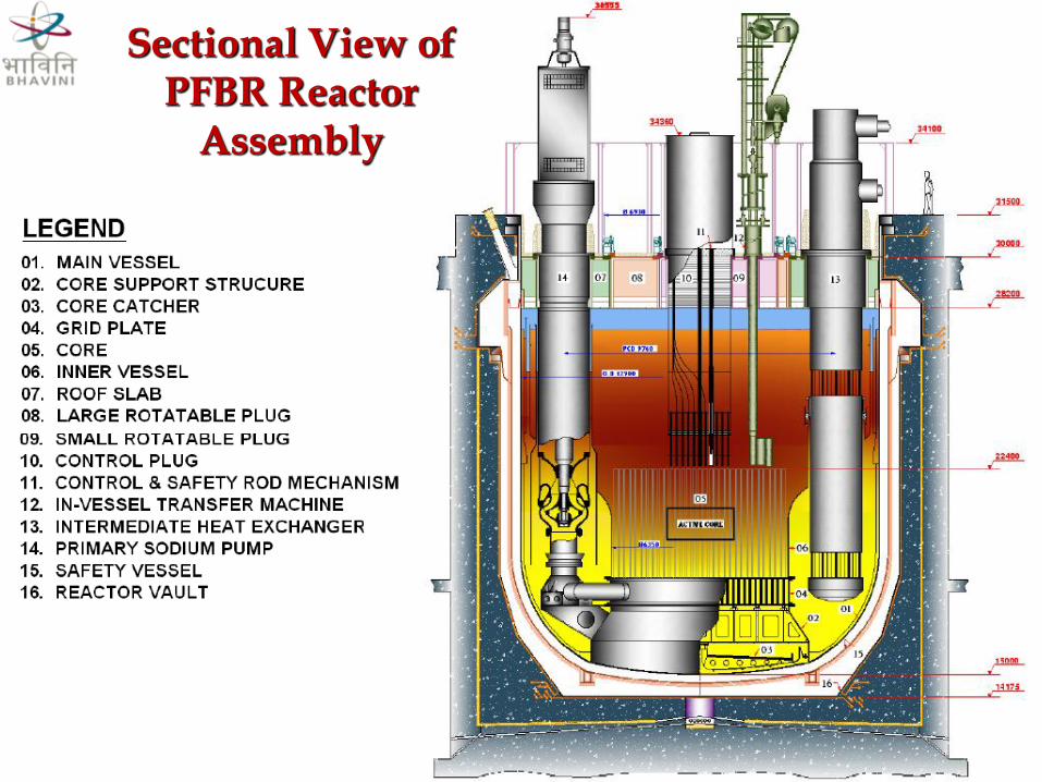
Sectional View of PFBR Reactor
Assembly

PFBR Plant Layout
SAS NICB PI

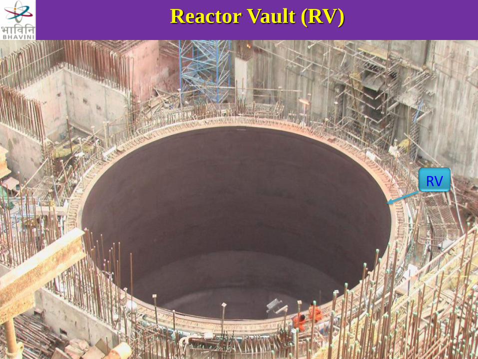
Reactor Vault (RV)
• The reactor assembly is housed in a concrete
vault lined with carbon steel called reactor vault.
• Tertiary containment for radioactive primary
sodium in Main Vessel in the highly unlikely
eventuality of leak in the both Main Vessel and
Safety Vessel.
• Reactor vault consists of Bottom Shield, Lower
lateral and Upper Lateral
Reactor Vault (RV)
RV

• PFBR Equipment erection was a challenging task where
thin walled vessels had transported and handled with utmost
precautions to avoid redial forces on the vessels, which
could buckle the vessels.
• There was a real challenge in lifting the vessels without
swing, placement of large size and heavy vessel at a
distance of 57 meters where the crane operator has no line
of sight to equipment's being erected.
• Lot of care had been taken during lifting, handling and
erection of thin walled ODC with innovative methods used
for lifting fixtures, guiding arrangements, alignment fixtures
and achieved the stringent erection tolerances.
EQUIPMENT ERECTION OF PFBR

Details of Safety Vessel(SV)
• SV dimensions (OD) - Ø 13540 mm x
12800mm (height)
• SV with thermal insulation(OD) - Ø 13840 mm
• SV shell thickness - 15 mm to 20 mm
• Material of Construction - SS 304LN
• Weight - 155 MT
• SV support flange (OD) - Ø 14960 mm
• RV opening (ID) - Ø 14200 mm approx.

• On outer surface of SV, metallic insulation (0.1 mm thick sheet) of 150 mm thickness is provided.
• Handling of SV during the erection was a very challenging task , because SS insulation was a fragile sheet and impossible to repair any defects occur on the same.

SV

Requirement of Load test before SV erection
• To handle such a huge ODC, there was a
requirement of conducting a load test to qualify
the lifting gear for handling of SV and validate
the SV erection procedure.
• Load test for base frame, rails and trolleys.
- Fabrication of test base frame of 16 m x 16 m

Load Testing of base frame, rails, trolleys
Test Base frame

Innovations in safety vessel erection
• PFBR project is being constructed very proximity to sea
shore and to handle such huge vessel (SV), the following
mock up tests were conducted to validate the SV
erection procedure.
• Mock up test for estimating wind load acting on SV
during shifting towards RV.
• Mock up test for smooth passage of SV inside RV

Mock up test for estimating wind load acting on SV
SV cruciform structure

Mock up test for smooth passage of SV into RV
SV diametrical mock-up structure

Schematic view for shifting of SV to RCB
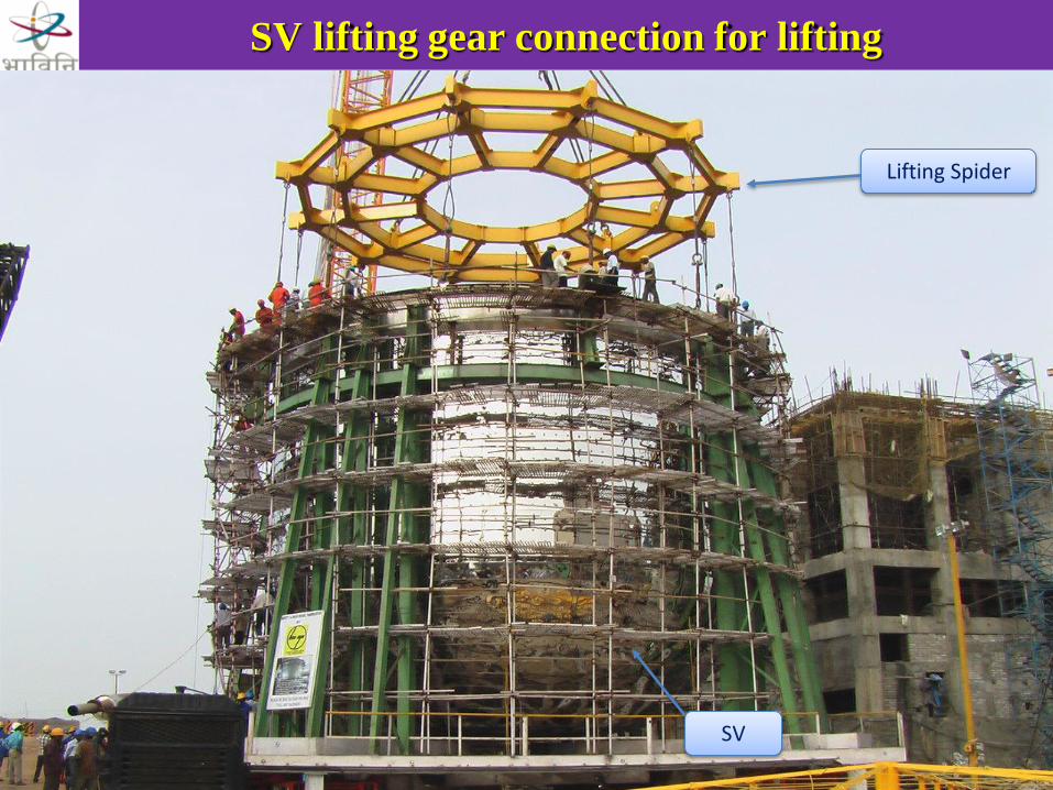
SV lifting gear connection for lifting
SV
Lifting Spider
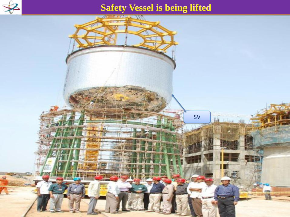
Safety Vessel is being lifted
SV

Safety Vessel is being lowered into Reactor Vault
SV
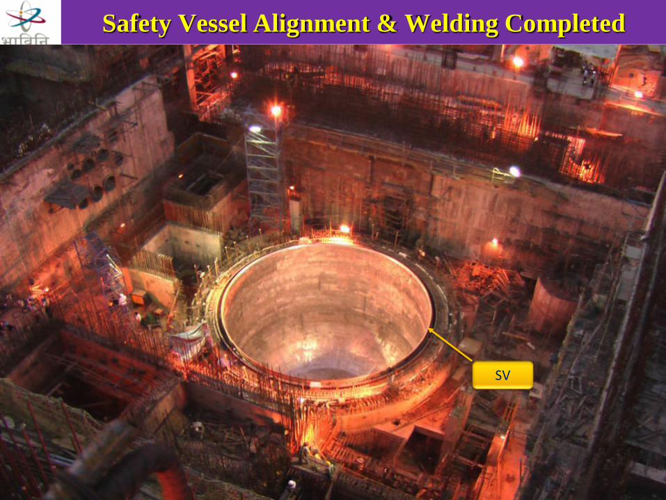
Safety Vessel Alignment & Welding Completed
SV

Challenges faced during SV erection
• Lifting & handling of such a huge cylindrical shell and
maintaining the same horizontally at top.
• Safely lowered into RV without any damage on SV
thermal insulation and achieved erection tolerances as
per design requirements

Details of Main Vessel (MV)
• MV dimensions (OD) - Ø 12900 mm x
12940mm (height)
• MV shell thickness - 25 mm to 30 mm
• Material of Construction - SS 316LN
• MV Weight with CC, CSS, MVCP - 202 MT
• The primary sodium circuit is housed in a single
vessel called main vessel and it is very important
reactor component which supports the Core
Catcher, Core Support Structure, Thermal baffle ,
Grid Plate, Inner Vessel and active Core.

MV
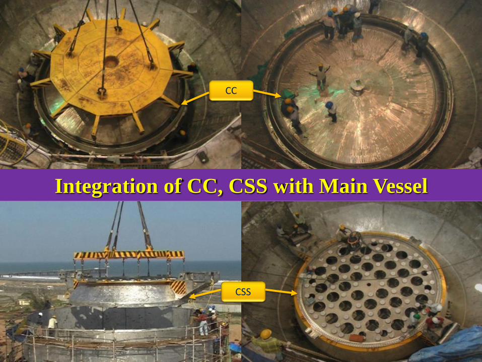
Integration of CC, CSS with Main Vessel
15/09/2008
CC
CSS

Load testing of MV handling gear
Connecting Rods
Ring Spider

Main Vessel Shifting
MV

Main Vessel lifting gear connection
MV
MV Lifting gear

Main Vessel is being lifted out from the supporting frame
structure MV

Main Vessel is being shifted towards RCB to lower into Safety vessel
MV
Crane

Main Vessel is being lowered into Safety vessel through Slab opening
MV
Ring Spider

MV Ring spider arms were seated on stools

Main Vessel is being lowered and aligned through guiding mechanisms
Radial Guiding System
Angular Guiding System
Ring spider Arm
MV

Grid plate Erection inside Main Vessel

Innovations in erecting Main Vessel
• 4 nos. of connecting rods were designed for MV load and
fabricated to achieve an uniform length, to avoid tilting of MV
during handling/erection.
• MV was lifted from below the centre of gravity point (CG) (i.e.
lifting points of MV are below CG point). To avoid toppling of
MV, 4 nos. of connecting rods were used for MV handling.
• The connection between lifting spider and component is a rigid
connection through the connecting rods. Since connecting rods
can take tensile and compressive loads.
• 4 nos. of lifting lugs have been welded on CSS such way that, it is
radially towards the centre of vessel to avoid dangling of MV
during handling of the same.
• Precise alignment of MV horizontality achieved by ring spider
arms and connecting rods.

Challenges faced during MV erection
• Lifting of main vessel was from below the CG point.
• Lifting of main vessel without swing and dangling.
• Lifting & handling of such a huge cylindrical shell and
maintaining the same horizontally at top.
• MV lowered safely into SV without any mechanical hindrance
within the small radial clearance between MV and RV.
• Precise alignment of MV with its internals to achieve
concentricity, axis orientation and horizontality.
Alignment requirements Target Achieved
GP Horizontality in MV mm) ±0.5 ± 0.45
GP vertical axis shift w.r.t. LRP support
flange (mm) Concentricity)
Within 3 1.32
Height between GP and LRP support
flange (mm)
11559 ± 1.5 mm 11557.5 to 11558
LRP flange horizontality (mm) ±1.0 ± 0.5

Details of Steam Generator (SG)
• Steam generator (SG) is a vertical, shell and tube type heat
exchanger and PFBR consists of 8 nos. of SGs.
• SG Material - 9Cr-1 Mo
• SG Overall dimensions - 26 m length xØ1500mm
• Weight of SG - 35MT
• Total nos. of tubes - 547
• Dimensions of each tube-17.2 mm x 2.3 mm wall thickness
• The main function of SG is to transfer the heat from
secondary sodium system to feed water there by generating
superheated steam.
INNOVATIONS IN SG ERECTION
• 26 meters length, 45 MT weight dummy Steam
generator structure was made exclusively for
conducting load test for transportation cum
vertical making structure.
• Mock up test was conducted with simulating the
actual SG handling conditions and validated SG
erection procedure.

Mock up test for SG
Dummy SG Structure
Vertical making of Dummy SG

Dummy SG fixing with SG support structure
SG vertical support structure
Transportation structure with dummy SG

Horizontal and vertical lifting of SG
SG handling gear
Steam generator
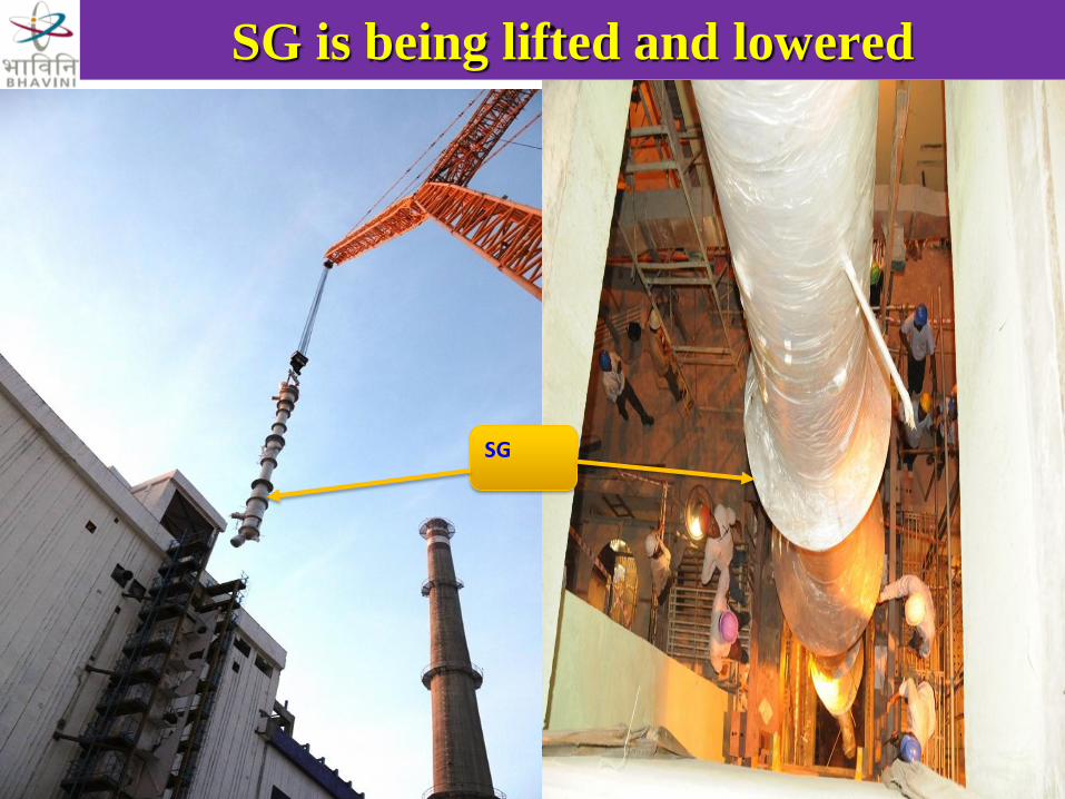
SG is being lifted and lowered
SG
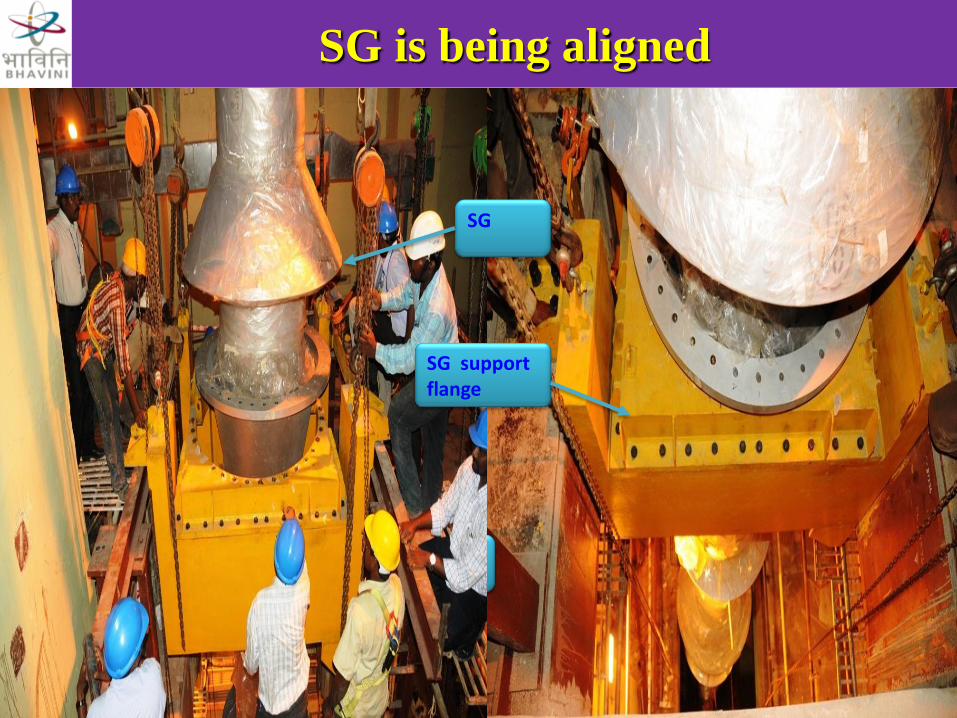
SG is being aligned
SG
SG
SG support flange

Challenges faced during SG erection
• Making of Steam generator horizontal to vertical
position without dangling.
• Lifting of Steam generator alone in horizontal
condition due to non-uniform mass

Thank You