innovative control at work - helgem.com.t · 1 aera® industrial mfc product guide 2 what is a mass...
TRANSCRIPT

Innovative Control at Work
Aera® Industrial MFC Product Guide

1
a e r a ® i n d u s t r i a l m f c p r o d u c t g u i d e

1
a e r a ® i n d u s t r i a l m f c p r o d u c t g u i d e
2 what is a mass flow controller?
3 fundamentals of mass flow measurement
4 nomenclature
5 operating principle
5 digital mass flow controller
6 set point accuracy
7 fc-7700 series analog mass flow controller
7 fc-7800 series analog mass flow controller
7 3-digit series mass flow controller
8 mach one™ digital mass flow controller
8 primaera® digital mass flow controller
9 mass flow controller (MFC) product line
10 dimensions
10 mass flow meter (MFM) product line
11 product configurator
12 electrical connectors
13 lx-1200 series liquid mass flow controller
13 usf ultrasonic flow meter
14 aera thermal vaporizer system
14 as-70/71, as-60a compact thermal vaporizer systems
15 gs-440a large capacity thermal vaporizer systems
15 pr100/200 pressure controller (regulator)
co
nt
en
ts

2
a e r a ® i n d u s t r i a l m f c p r o d u c t g u i d e
3
a e r a ® i n d u s t r i a l m f c p r o d u c t g u i d e
Advanced Energy’s Aera® mass flow products have maintained a reputation for high quality products and superior worldwide sales, service, and support. Our pioneering developments helped us to emerge as a technology leader in industrial flow markets, including the industrial vacuum and coating industries. Today, Aera mass flow products integrate the latest in innovative technology to provide you with the ultimate in reliable, accurate, and cost-effective mass flow controllers (MFCs) and mass flow meters (MFMs) for advanced process control. Our promise to exceed expectations for quality, timeliness, and cost sets us apart from competition. We continue to deliver world-class products through dedicated research and a strong commitment to customer partnerships—giving you more security, more confidence, and more possibilities in mass flow control.
what is a mass flow controller (MFC)?A mass flow controller is a closed-loop device that sets, measures, and controls
the flow of a particular gas. Aera MFCs provide the most precise flow control
at the most cost-effective price.
mass flow controller performance and reliabil ityMFC manufacturers go to great lengths to explain why their products should
outperform others, often focusing on a few design features. But it is not enough
to define MFC performance on the basis of a few parameters— today’s critical
processes demand MFCs that deliver outstanding performance and reliability.
The primary factors include:
accuracy
The difference between the actual
flow of an MFC and that of a primary
standard at any set point
repeatability
Repeatability of actual flow for an
MFC or from one MFC to another
at any set point
linearity
Straightness of the curve of actual
flow versus set point; in other words,
accuracy over the entire flow range
calibration drift
The change in the curve of actual
flow versus set point due to aging
effects of some of the component
parts that comprise an MFC
stability
The ability of an MFC to maintain
stable flow levels through short-
term effects, such as pressure and
temperature changes, and through
long-term effects, such as component-
part degradation

2
a e r a ® i n d u s t r i a l m f c p r o d u c t g u i d e
3
a e r a ® i n d u s t r i a l m f c p r o d u c t g u i d e
response or settling time
The time it takes for actual flow
to stabilize after a set point change
overshoot and undershoot control
Any spike or dip in the response
curve of actual flow versus time
pressure change response
The time that it takes for actual
flow to stabilize after a sudden
change in gas input pressure
temperature change effects
The stability of flow during
ambient temperature variations
Aera MFCs offer state-of-the-art
performance and reliability in all
critical parameters.
Aera MFCs and MFMs have a zero drift of less than 0.5 percent of full scale over a period of one year and are guaranteed to have a zero drift of less than 1 percent of full scale over a period of one year.
Aera MFCs and MFMs have the lowest return rates within one year of shipment (< 0.5 percent).
Aera MFCs and MFMs are highly resistant to the effects from strong RF fields.
No Flow Condition
Gas Flow
Sensor Temperature Profile
fundamentals of mass flow measurementThe heart of a mass flow controller is a thermal mass flow sensor. It consists
of a small bore tube with two resistance thermometer elements wound around
the outside of the tube. The sensor tube is heated by applying an electric current
to the elements. A constant proportion of gas flows through the sensor tube, and
the cooling effect creates a temperature differential between the two elements.
The temperature differential is measured as an electric signal.
The temperature differential created between the elements is dependent
on the mass flow of the gas and is a function of its density, specific heat,
and flow rate. Mass flow is normally calculated in terms of volume of the gas,
either in standard cubic centimeters per minute (sccm) or in standard liters
per minute (slm). The electronics of a mass flow controller convert mass flow
into volume flow at standard conditions of 0°C (32°F) and 1 atmosphere.
Because the volume of 1 mole of an ideal gas at 0°C and 1 atmosphere occupies
22.4 liters, a set point of 22.4 slm will cause 1 mole of gas to flow during 1 minute.
4
a e r a ® i n d u s t r i a l m f c p r o d u c t g u i d e
5
a e r a ® i n d u s t r i a l m f c p r o d u c t g u i d e
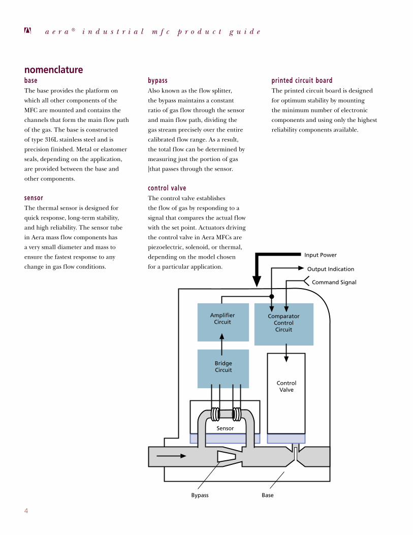
nomenclaturebaseThe base provides the platform on
which all other components of the
MFC are mounted and contains the
channels that form the main flow path
of the gas. The base is constructed
of type 316L stainless steel and is
precision finished. Metal or elastomer
seals, depending on the application,
are provided between the base and
other components.
sensorThe thermal sensor is designed for
quick response, long-term stability,
and high reliability. The sensor tube
in Aera mass flow components has
a very small diameter and mass to
ensure the fastest response to any
change in gas flow conditions.
bypassAlso known as the flow splitter,
the bypass maintains a constant
ratio of gas flow through the sensor
and main flow path, dividing the
gas stream precisely over the entire
calibrated flow range. As a result,
the total flow can be determined by
measuring just the portion of gas
|that passes through the sensor.
control valveThe control valve establishes
the flow of gas by responding to a
signal that compares the actual flow
with the set point. Actuators driving
the control valve in Aera MFCs are
piezoelectric, solenoid, or thermal,
depending on the model chosen
for a particular application.
printed circuit boardThe printed circuit board is designed
for optimum stability by mounting
the minimum number of electronic
components and using only the highest
reliability components available.
Input Power
Output Indication
Command Signal
AmplifierCircuit
ComparatorControlCircuit
BridgeCircuit
Sensor
ControlValve
Bypass Base

4
a e r a ® i n d u s t r i a l m f c p r o d u c t g u i d e
5
a e r a ® i n d u s t r i a l m f c p r o d u c t g u i d e
operating principle The bypass forces a constant proportion of the incoming gas to be fed into the sensor. The gas flow through the sensor tube causes heat to transfer from the upstream resistance-thermometer element to the downstream resistance-thermometer element.
This temperature differential is linearized and amplified into a 0 to 5 volt flow output signal by a bridge circuit.
The output signal is compared with the external set point signal to the mass flow controller.
The error signal that results from comparing the output signal with the set point signal directs the control valve to open or close to maintain a constant flow at the set point level.
digital mass flow controllerA conventional analog mass flow controller contains an operational amplifier
and an analog arithmetic control circuit. Digital MFCs convert the analog signal
of the sensor output into a digital signal and have a digital CPU for subsequent
data processing. Digitizing the circuitry improves response time and eliminates
the drift and inaccuracies that are inherent with analog instrumentation.

6
a e r a ® i n d u s t r i a l m f c p r o d u c t g u i d e
7
a e r a ® i n d u s t r i a l m f c p r o d u c t g u i d e
set point accuracyAnalog MFC accuracy is a percentage of full-scale flow. Therefore, the flow
error increases as the MFC is throttled down. The accuracy of a digital MFC is
a percentage of set point from 100 percent down to 25 percent of the flow range.
Digital MFCs are accurate to 1 percent of the set point down to 25 percent of the
flow range and accurate to 0.25 percent of full scale below 25 percent of the flow
range. Repeatability is 0.2 percent of full scale.
Aera digital MFCs (DMFCs) allow unlimited gas selection without recalibration.
This capability is based on storing multiple surrogate gas calibration templates in
memory, in contrast to competitive digital MFCs that store only one surrogate
gas calibration curve in memory. Multiple surrogate gas calibration allows you
to significantly reduce your inventory of spare MFCs since one DMFC can
replace multiple MFCs.
�������
������
� � �� �� �� �� �� �� �� �� �� ����
�
��
��
��
��
��
��
��
��
��
�������������������������������������
����
����
����
����
�����
����
���
����
�
6
a e r a ® i n d u s t r i a l m f c p r o d u c t g u i d e
7
a e r a ® i n d u s t r i a l m f c p r o d u c t g u i d e
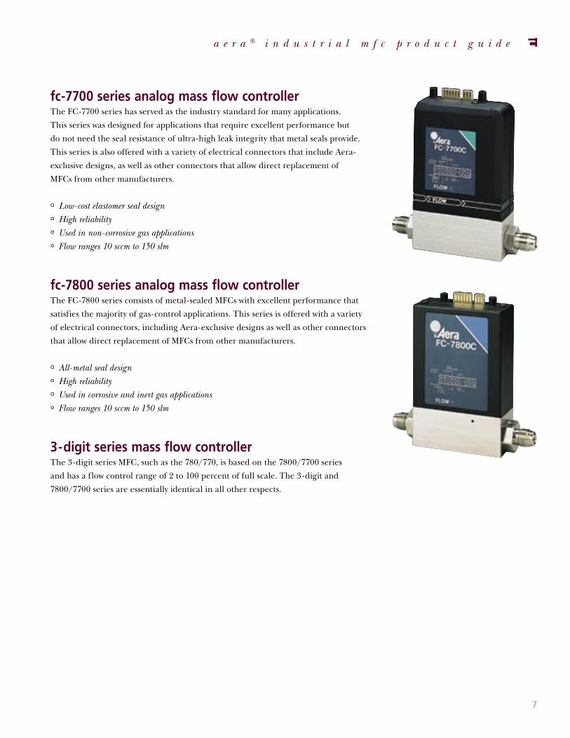
fc-7700 series analog mass flow controllerThe FC-7700 series has served as the industry standard for many applications.
This series was designed for applications that require excellent performance but
do not need the seal resistance of ultra-high leak integrity that metal seals provide.
This series is also offered with a variety of electrical connectors that include Aera-
exclusive designs, as well as other connectors that allow direct replacement of
MFCs from other manufacturers.
Low-cost elastomer seal design High reliability Used in non-corrosive gas applications Flow ranges 10 sccm to 150 slm
fc-7800 series analog mass flow controllerThe FC-7800 series consists of metal-sealed MFCs with excellent performance that
satisfies the majority of gas-control applications. This series is offered with a variety
of electrical connectors, including Aera-exclusive designs as well as other connectors
that allow direct replacement of MFCs from other manufacturers.
All-metal seal design High reliability Used in corrosive and inert gas applications Flow ranges 10 sccm to 150 slm
3-digit series mass flow controllerThe 3 -digit series MFC, such as the 780/770, is based on the 7800/7700 series
and has a flow control range of 2 to 100 percent of full scale. The 3 -digit and
7800/7700 series are essentially identical in all other respects.

8
a e r a ® i n d u s t r i a l m f c p r o d u c t g u i d e
9
a e r a ® i n d u s t r i a l m f c p r o d u c t g u i d e
mach one™ digital mass flow controllerThe revolutionary Mach One digital, pressure-based mass flow controller integrates
advanced sonic nozzle technology with the ability to measure upstream line pressure
and temperature.
All-metal seal design New, pressure-based MFC technology Used in inert gas applications High-accuracy, digital electronics with RS-485 communications Fast response Flow ranges from 10 sccm to 10 slm
primaera® digital mass flow controllerThe PrimAera is a true digital mass flow controller, designed with Aera’s field-
proven MFC components that have delivered outstanding performance and
reliability in the field. This solid foundation, along with 21st century electronics,
provides the ultimate in control and communications capability.
All-metal seal design Fast response DeviceNet™ communications Used in corrosive and inert gas applications Available in VCR and IGS configurations flow ranges from 10 sccm to 50 slm
Available as gas-specific or multi-gas models. Multi-gas models allow you
to select unlimited gases without recalibration, providing a significant reduction
in the number of spares required.
8
a e r a ® i n d u s t r i a l m f c p r o d u c t g u i d e
9
a e r a ® i n d u s t r i a l m f c p r o d u c t g u i d e
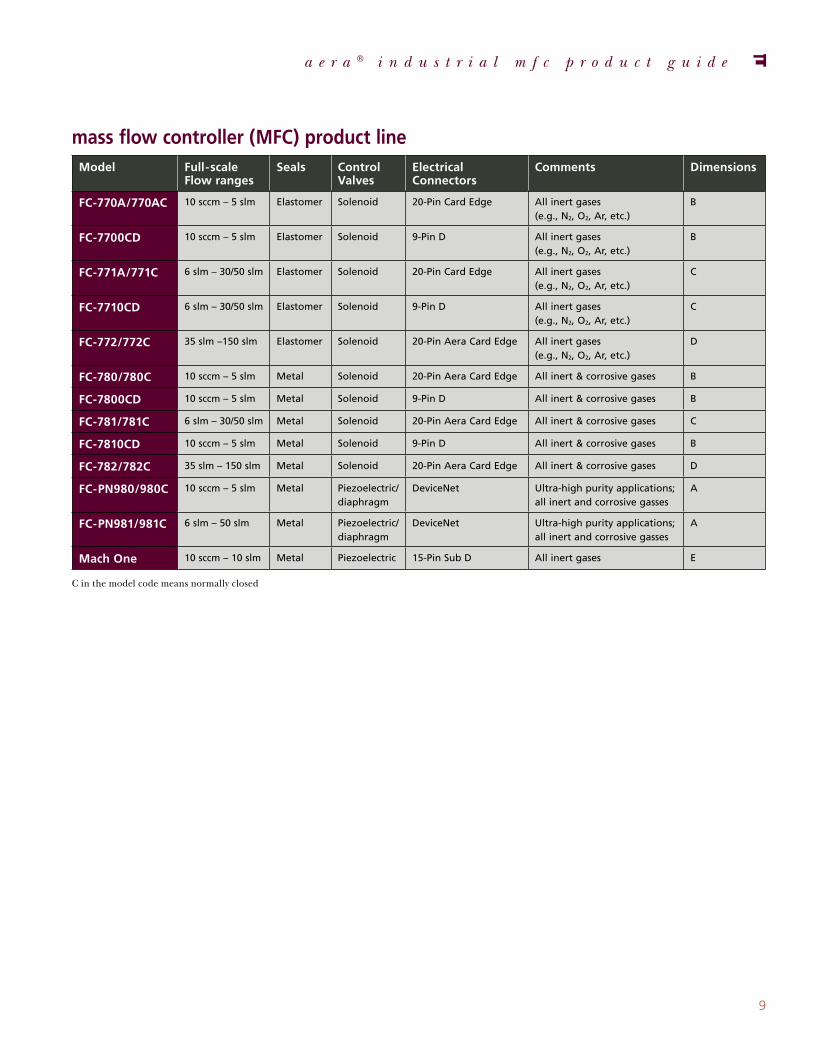
mass flow controller (MFC) product lineModel Full-scale
Flow rangesSeals Control
ValvesElectricalConnectors
Comments Dimensions
FC-770A/770AC 10 sccm – 5 slm Elastomer Solenoid 20-Pin Card Edge All inert gases (e.g., N2, O2, Ar, etc.)
B
FC-7700CD 10 sccm – 5 slm Elastomer Solenoid 9-Pin D All inert gases(e.g., N2, O2, Ar, etc.)
B
FC-771A/771C 6 slm – 30/50 slm Elastomer Solenoid 20-Pin Card Edge All inert gases(e.g., N2, O2, Ar, etc.)
C
FC-7710CD 6 slm – 30/50 slm Elastomer Solenoid 9-Pin D All inert gases(e.g., N2, O2, Ar, etc.)
C
FC-772/772C 35 slm –150 slm Elastomer Solenoid 20-Pin Aera Card Edge All inert gases(e.g., N2, O2, Ar, etc.)
D
FC-780/780C 10 sccm – 5 slm Metal Solenoid 20-Pin Aera Card Edge All inert & corrosive gases B
FC-7800CD 10 sccm – 5 slm Metal Solenoid 9-Pin D All inert & corrosive gases B
FC-781/781C 6 slm – 30/50 slm Metal Solenoid 20-Pin Aera Card Edge All inert & corrosive gases C
FC-7810CD 10 sccm – 5 slm Metal Solenoid 9-Pin D All inert & corrosive gases B
FC-782/782C 35 slm – 150 slm Metal Solenoid 20-Pin Aera Card Edge All inert & corrosive gases D
FC-PN980/980C 10 sccm – 5 slm Metal Piezoelectric/diaphragm
DeviceNet Ultra-high purity applications; all inert and corrosive gasses
A
FC-PN981/981C 6 slm – 50 slm Metal Piezoelectric/diaphragm
DeviceNet Ultra-high purity applications; all inert and corrosive gasses
A
Mach One 10 sccm – 10 slm Metal Piezoelectric 15-Pin Sub D All inert gases E
C in the model code means normally closed
10
a e r a ® i n d u s t r i a l m f c p r o d u c t g u i d e
11
a e r a ® i n d u s t r i a l m f c p r o d u c t g u i d e
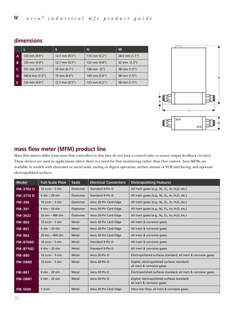
dimensionsL S H W
A 124 mm (4.9”) 12.7 mm (0.5”) 133 mm (5.2”) 28.6 mm (1.1”)
B 124 mm (4.9”) 12.7 mm (0.5”) 122 mm (4.8”) 32 mm (1.3”)
C 151 mm (5.9”) 19 mm (0.7”) 128 mm (5”) 38 mm (1.5”)
D 183.8 mm (7.2”) 15 mm (0.6”) 149 mm (5.9”) 38 mm (1.5”)
E 124 mm (4.9”) 12.7 mm (0.5”) 133 mm (5.2”) 38 mm (1.5”)
mass flow meter (MFM) product lineMass flow meters differ from mass flow controllers in that they do not have a control valve or sensor output feedback circuitry.
These devices are used in applications where there is a need for flow monitoring rather than flow control. Aera MFMs are
available in models with elastomer or metal seals, analog or digital operation, surface-mount or VCR interfacing, and optional
electropolished surfaces.
Model Full-Scale Flow Seals Electrical Connectors Distinquishing Features
FM-3700 D 10 sccm – 5 slm Elastomer Standard 9-Pin D All inert gases (e.g., N2, O2, Ar, H2O, etc.)
FM-3710 D 6 slm – 20 slm Elastomer Standard 9-Pin D All inert gases (e.g., N2, O2, Ar, H2O, etc.)
FM-390 10 sccm – 5 slm Elastomer Aera 20-Pin Card Edge All inert gases (e.g., N2, O2, Ar, H2O, etc.)
FM-391 6 slm – 50 slm Elastomer Aera 20-Pin Card Edge All inert gases (e.g., N2, O2, Ar, H2O, etc.)
FM-362J 20 slm – 400 slm Elastomer Aera 20-Pin Card Edge All inert gases (e.g., N2, O2, Ar, H2O, etc.)
FM-860 10 sccm – 5 slm Metal Aera 20-Pin Card Edge All inert & corrosive gases
FM-861 6 slm – 20 slm Metal Aera 20-Pin Card Edge All inert & corrosive gases
FM-862 20 slm – 400 slm Metal Aera 20-Pin Card Edge All inert & corrosive gases
FM-8700D 10 sccm – 5 slm Metal Standard 9-Pin D All inert & corrosive gases
FM-8710D 6 slm – 20 slm Metal Standard 9-Pin D All inert & corrosive gases
FM-880 10 sccm – 5 slm Metal Aera 20-Pin D Electropolished surfaces standard; all inert & corrosive gases
FM-D880 10 sccm – 5 slm Metal Aera 20-Pin D Digital; electropolished surfaces standard; all inert & corrosive gases
FM-881 6 slm – 20 slm Metal Aera 20-Pin D Electropolished surfaces standard; all inert & corrosive gases
FM-D881 6 slm – 20 slm Metal Aera 20-Pin D Digital; electropolished surfaces standard; all inert & corrosive gases
FM-1000 1 sccm Metal Aera 20-Pin Card Edge Ultra-low flow; all inert & corrosive gases
10
a e r a ® i n d u s t r i a l m f c p r o d u c t g u i d e
11
a e r a ® i n d u s t r i a l m f c p r o d u c t g u i d e
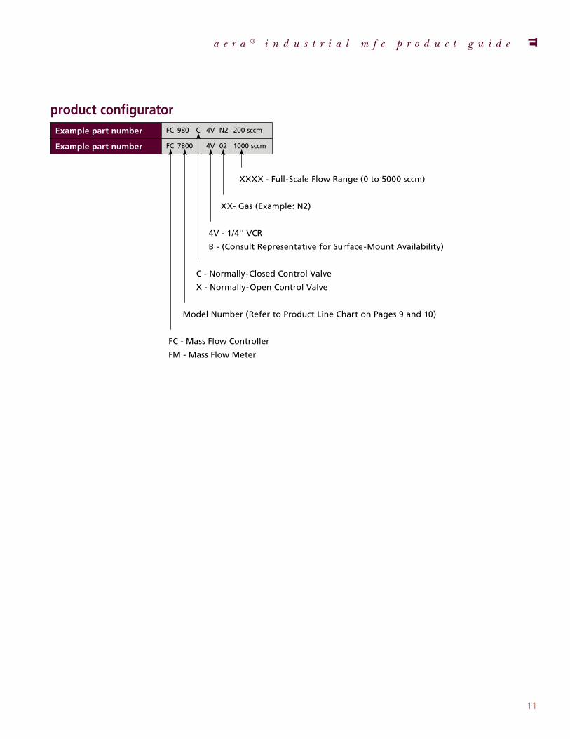
product configuratorExample part number FC 980 C 4V N2 200 sccm
Example part number FC 7800 4V 02 1000 sccm
FC - Mass Flow Controller
FM - Mass Flow Meter
Model Number (Refer to Product Line Chart on Pages 9 and 10)
C - Normally-Closed Control Valve
X - Normally-Open Control Valve
4V - 1/4'' VCR
B - (Consult Representative for Surface-Mount Availability)
XX- Gas (Example: N2)
XXXX - Full-Scale Flow Range (0 to 5000 sccm)
12
a e r a ® i n d u s t r i a l m f c p r o d u c t g u i d e
13
a e r a ® i n d u s t r i a l m f c p r o d u c t g u i d e
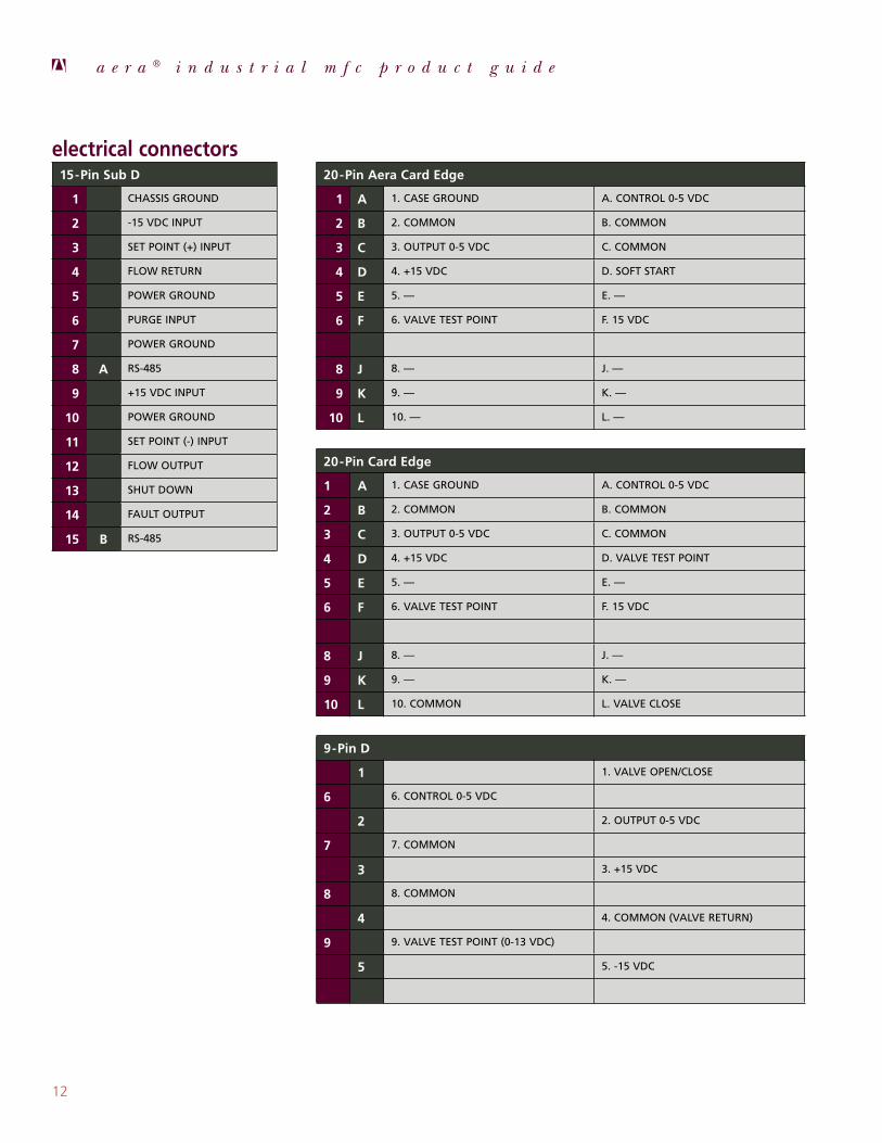
electrical connectors15-Pin Sub D
1 CHASSIS GROUND
2 -15 VDC INPUT
3 SET POINT (+) INPUT
4 FLOW RETURN
5 POWER GROUND
6 PURGE INPUT
7 POWER GROUND
8 A RS-485
9 +15 VDC INPUT
10 POWER GROUND
11 SET POINT (-) INPUT
12 FLOW OUTPUT
13 SHUT DOWN
14 FAULT OUTPUT
15 B RS-485
20-Pin Aera Card Edge
1 A 1. CASE GROUND A. CONTROL 0-5 VDC
2 B 2. COMMON B. COMMON
3 C 3. OUTPUT 0-5 VDC C. COMMON
4 D 4. +15 VDC D. SOFT START
5 E 5. — E. —
6 F 6. VALVE TEST POINT F. 15 VDC
8 J 8. — J. —
9 K 9. — K. —
10 L 10. — L. —
20-Pin Card Edge
1 A 1. CASE GROUND A. CONTROL 0-5 VDC
2 B 2. COMMON B. COMMON
3 C 3. OUTPUT 0-5 VDC C. COMMON
4 D 4. +15 VDC D. VALVE TEST POINT
5 E 5. — E. —
6 F 6. VALVE TEST POINT F. 15 VDC
8 J 8. — J. —
9 K 9. — K. —
10 L 10. COMMON L. VALVE CLOSE
9-Pin D
1 1. VALVE OPEN/CLOSE
6 6. CONTROL 0-5 VDC
2 2. OUTPUT 0-5 VDC
7 7. COMMON
3 3. +15 VDC
8 8. COMMON
4 4. COMMON (VALVE RETURN)
9 9. VALVE TEST POINT (0-13 VDC)
5 5. -15 VDC
12
a e r a ® i n d u s t r i a l m f c p r o d u c t g u i d e
13
a e r a ® i n d u s t r i a l m f c p r o d u c t g u i d e
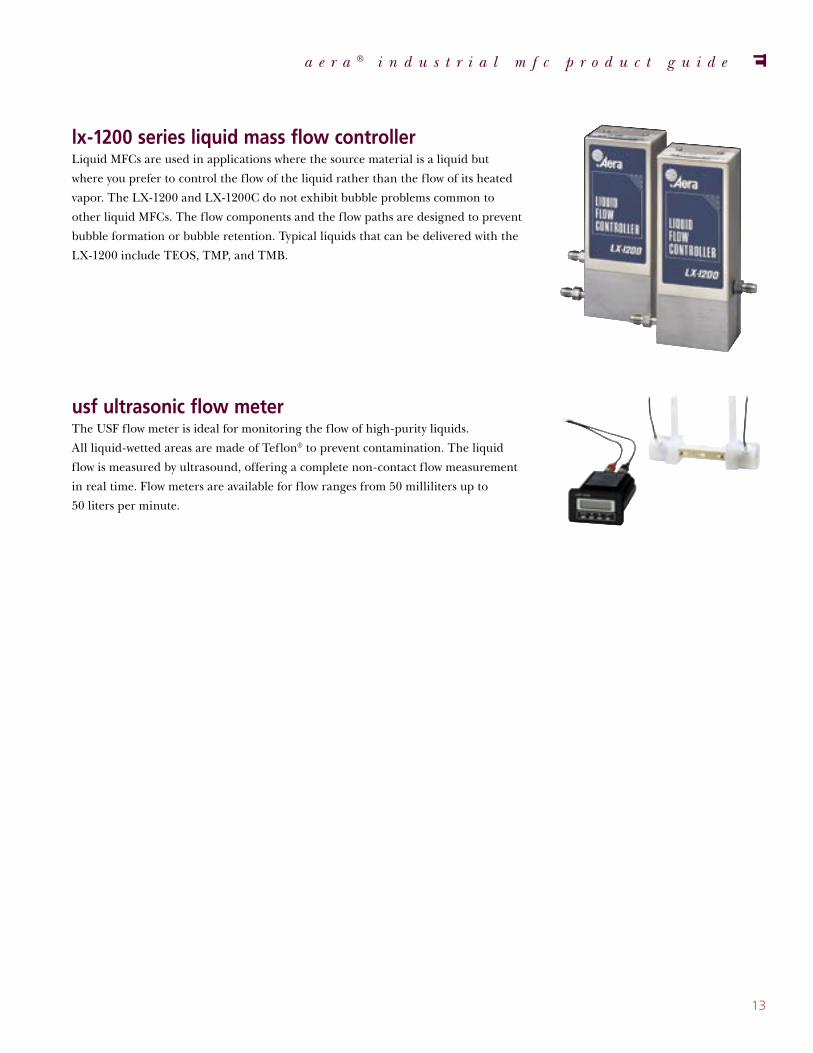
lx-1200 series liquid mass flow controllerLiquid MFCs are used in applications where the source material is a liquid but
where you prefer to control the flow of the liquid rather than the flow of its heated
vapor. The LX-1200 and LX-1200C do not exhibit bubble problems common to
other liquid MFCs. The flow components and the flow paths are designed to prevent
bubble formation or bubble retention. Typical liquids that can be delivered with the
LX-1200 include TEOS, TMP, and TMB.
usf ultrasonic flow meterThe USF flow meter is ideal for monitoring the flow of high-purity liquids.
All liquid-wetted areas are made of Teflon® to prevent contamination. The liquid
flow is measured by ultrasound, offering a complete non-contact flow measurement
in real time. Flow meters are available for flow ranges from 50 milliliters up to
50 liters per minute.
14
a e r a ® i n d u s t r i a l m f c p r o d u c t g u i d e
15
a e r a ® i n d u s t r i a l m f c p r o d u c t g u i d e
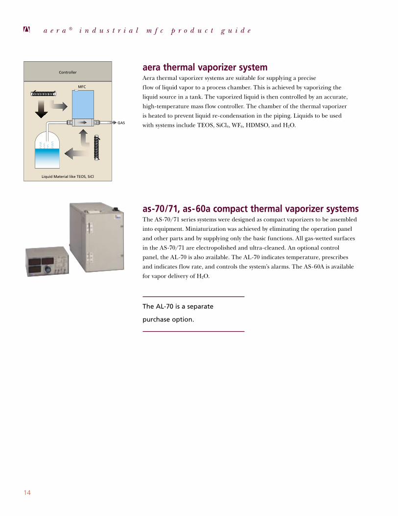
aera thermal vaporizer systemAera thermal vaporizer systems are suitable for supplying a precise
flow of liquid vapor to a process chamber. This is achieved by vaporizing the
liquid source in a tank. The vaporized liquid is then controlled by an accurate,
high-temperature mass flow controller. The chamber of the thermal vaporizer
is heated to prevent liquid re-condensation in the piping. Liquids to be used
with systems include TEOS, SiCl4, WF6, HDMSO, and H2O.
as-70/71, as-60a compact thermal vaporizer systemsThe AS -70/71 series systems were designed as compact vaporizers to be assembled
into equipment. Miniaturization was achieved by eliminating the operation panel
and other parts and by supplying only the basic functions. All gas-wetted surfaces
in the AS -70/71 are electropolished and ultra-cleaned. An optional control
panel, the AL-70 is also available. The AL-70 indicates temperature, prescribes
and indicates flow rate, and controls the system’s alarms. The AS -60A is available
for vapor delivery of H2O.
The AL-70 is a separate
purchase option.
Controller
GAS
Liquid Material like TEOS, SiCl
MFC
14
a e r a ® i n d u s t r i a l m f c p r o d u c t g u i d e
15
a e r a ® i n d u s t r i a l m f c p r o d u c t g u i d e
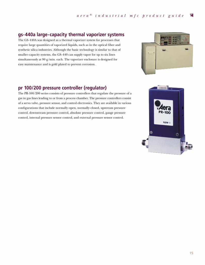
gs-440a large-capacity thermal vaporizer systemsThe GS-440A was designed as a thermal vaporizer system for processes that
require large quantities of vaporized liquids, such as in the optical fiber and
synthetic silica industries. Although the basic technology is similar to that of
smaller-capacity systems, the GS -440 can supply vapor for up to six lines
simultaneously at 90 g/min. each. The vaporizer enclosure is designed for
easy maintenance and is gold plated to prevent corrosion.
pr 100/200 pressure controller (regulator)The PR-100/200 series consists of pressure controllers that regulate the pressure of a
gas in gas lines leading to or from a process chamber. The pressure controllers consist
of a servo valve, pressure sensor, and control electronics. They are available in various
configurations that include normally-open, normally-closed, upstream pressure
control, downstream pressure control, absolute pressure control, gauge pressure
control, internal pressure sensor control, and external pressure sensor control.

16
a e r a ® i n d u s t r i a l m f c p r o d u c t g u i d e
17
a e r a ® i n d u s t r i a l m f c p r o d u c t g u i d e
16
a e r a ® i n d u s t r i a l m f c p r o d u c t g u i d e
17
a e r a ® i n d u s t r i a l m f c p r o d u c t g u i d e
a e r a ® i n d u s t r i a l m f c p r o d u c t g u i d e
United KingdomT: 44.1869.320022F: 44.1869.325004
GermanyT: 49.711.779270F: 49.711.7778700
KoreaT: 82.3 1.705.2100F: 82.31.705. 2766
JapanT: 81.3.32351511F: 81.3.32353580
TaiwanT: 886.2.82215599F: 886.2.82215050
ChinaT: 86.21.58579011F: 86.21.58579003
For more information on non-vacuum products and applications, contact EMCO Sales:Advanced Energy 1625 Sharp Point Drive Fort Collins, CO 80525 USAT: 800.446.9167 or 970.221.4670 F: 970.221.5583 www.emcoflow.com
For information on vacuum-related products and applications, contact Advanced Energy Sales:Advanced Energy Industries, Inc. 1625 Sharp Point Drive Fort Collins, Colorado 80525 T: 800.446.9167 or 970.221.4670 F: 970.221.5583 [email protected] www.advanced-energy.com
© Advanced Energy Industries, Inc. 2003 All rights reserved. Printed in U.S.A.SL-AeraIndLNCD-290-01 XM 08/03
Advanced Energy® is a registered trademark of Advanced Energy Industries, Inc. Aera® is a registered trademark of Advanced Energy Industries, Inc.VCR® is a registered trademark of Cajon Company. DeviceNet™ is a trademark of Open DeviceNet Vendor Association, Inc.Teflon® is a registered trademark of E.I. du Pont de Nemours and Company.