innovative end/expansion joint solution for lysaght … · 2019-12-10 · lp ® 2 lysaght...
TRANSCRIPT

TRIM-KLIP®
INNOVATIVE END/EXPANSION JOINT SOLUTION FOR LYSAGHT TRIMDEK®
TRIM
-KLIP
®2
LYSAGHT TRIM-KLIP®
The new TRIM-KLIP® system provides installers with a quick and easy end joint/expansion joint solution between overlapping sheets of TRIMDEK®.
The TRIM-KLIP® system comprises a fully engineered steel bracket and a custom profiled weather strip. The TRIM-KLIP® bracket is sandwiched between the overlapping sheets at the ribs and is fixed using standard pierce-fixed screw fasteners.
BENEFITS OF TRIM-KLIP®
• Low profile system maintains clean, long run roof lines of roofing.
• A cost effective way to achieve a long-length roofing design, even when using shorter roof sheets.
• Fast and easy to install - minimal change to current installation practice.
• Standard pierce-fixed screw fasteners
• Tested and proven in our NATA-accredited testing facility. If installed correctly, will preserve all existing roofing warranties.
• Safe and effective weather resistant seal.
• Allows thermal movement.
• No special purlin detailing required - saves you time and money.
• Fully designed and engineered quality components.
• As a stand-alone solution, compatible with translucent sheeting.
BACKGROUND ON THERMAL EXPANSION
All metals expand and contract with changes in temperature. Although steel is by far the least affected of all the metals commonly used for roof and wall cladding, the changes in length experienced in very long runs of roofing are significant.
When TRIM-KLIP® is used, the length of each individual sheet is necessarily shorter, thus reducing the impact of thermal movement.
TRIM-KLIP® IS AN EXPANSION JOINT/LAP JOINT HYBRID
An expansion joint involves overlapping the ends of the upper sheets over the ends of the lower sheets. With the TRIM-KLIP® system, no extra purlin is needed at the joint as is the current practice with expansion joints.
A profiled weather strip provides protection from wind-blown rain and is made from closed cell polyethylene foam. It is sandwiched between the upper and lower sheets to provide a weather resistant barrier from wind driven rainwater. It also provides air flow and ventilation to reduce likelihood of potential trapped condensate or moisture build-up.
The TRIM-KLIP® bracket is Australian-made Next Generation ZINCALUME® Steel and is an assembly of two pieces. (Figure 4) The two pieces are pressed metal components (an upper and lower piece) inter-locked together and the assembled bracket saddles the rib of the roofing profile. The bracket, as an assembly, is placed on the rib of the lower sheet and the lower piece (base) of the bracket is fixed, via a pre-formed hole, through the rib to the support underneath. The rib of the upper sheet is pierce-fixed directly to the upper piece of the bracket. The upper piece of the bracket is free to move longitudinally relative to the lower piece.
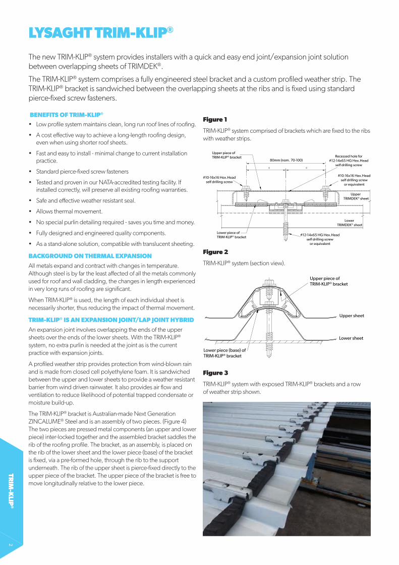
Figure 3
TRIM-KLIP® system with exposed TRIM-KLIP® brackets and a row of weather strip shown.
Figure 1
TRIM-KLIP® system comprised of brackets which are fixed to the ribs with weather strips.
Figure 2
TRIM-KLIP® system (section view).
Upper piece ofTRIM-KLIP® bracket
Lower piece ofTRIM-KLIP® bracket
Upper TRIMDEK® sheet
Lower TRIMDEK® sheet
80mm (nom. 70-100)Recessed hole for
#12-14x65 HG Hex.Headself drilling screw
#12-14x65 HG Hex.Headself drilling screw
or equivalent
#10-16x16 Hex.Headself drilling screw
#10-16x16 Hex.Headself drilling screw
or equivalent
Upper piece ofTRIM-KLIP® bracket
Lower piece (base) ofTRIM-KLIP® bracket
Lower sheet
Upper sheet

TRIM
-KLI
P®
3
TRIM-KLIP® JOINT LAYOUT AND FIXING
The following layout will allow normal pierce-fixed screw fastening at the support and still allow thermal movement to occur at the TRIM-KLIP®.
The TRIM-KLIP® system should consist of a TRIM-KLIP® bracket at each rib with weather strips, as per Figure 5. The weather strips are secured in place by being sandwiched between the lower portion of the bracket and the lower roofing sheet. The lower portion of the bracket is secured in-place by the standard roofing screws through the pre-formed hole and through the roofing rib to the support underneath.
The upper roofing sheet is placed so that the ribs sit upon the upper portion of the TRIM-KLIP® bracket. The upper sheet is then fixed to the upper portion of the TRIM-KLIP® bracket using two standard walling screws. Refer to Table 1 for fastener requirements.
TESTING
The TRIM-KLIP® system has been tested for performance in wind uplift and weather-resistance at Lysaght’s NATA-accredited materials science testing laboratory. This means you can be confident that TRIM-KLIP® will perform to specification when installed according to our design limitations and installation guidelines.
Table 1
Fasteners for TRIM-KLIP® Installation.
Bracket portion No. per bracket Fastener specification
Lower 1#12-14x45 Metal Teks HG, HH or AutoTeks M5.5-14x50
Upper 2 #10-16x16 Metal Teks, HH
Figure 6
Weather test rig is used to test weather resistance by blowing simulated wind borne rain.
Figure 7
Wind uplift tests were performed to ensure TRIM-KLIP® bracket met the performance standards required.
Figure 4
TRIM-KLIP® bracket comprising upper and lower pieces which allows relative movement between the two pieces.
Upper piece
Lower piece
Figure 5
Layout details of TRIM-KLIP® system at support.
400mm (max.) 330mm (min.)
250mm (max.) 215mm (min.)
150mm (max.) 115mm (min.)
130mm (nom.)
Upper sheet
Lower sheet Turn-up pans
Turn-down pans
TRIM-KLIP®
Weather strip(Primary)
Weather strip(Secondary)
Cladding support

TRIM
-KLIP
®4
INSTALLATIONI TRIMDEK® SPAN CONSIDERATIONS
The spans of the roofing at the joint must be kept within the following limits:
a. The roofing sheets on either side of the TRIM-KLIP® joint are not to exceed the maximum recommended END span of the roofing.
b. The purlin spacing (roofing span) must be of a practical range – typically 900mm or greater.
II WEATHER STRIPS
These guidelines describe the laying two rows of weather strips, however in most cases only a single row is required. When using a single row of weather strip (primary weather strip) it must be located on the high side of the TRIM-KLIP® brackets. Two rows of weather strips are recommended in translucent sheet installation or where the roof is exposed to a severe combination of very high wind and high rain. The weather strips are interlocked end-to-end in the traditional way to form a continuous row.
III PACKERS
Packers (10mm thick) may be required to achieve a more gradual change in the roof slope and to ensure drainage at the joint. The packer is positioned on the lowest purlin of the upper sheet for roofs at the TRIM-KLIP® joint system (see Figure 9).
Packers would only be required on shallow roof slopes and when the purlin spacing for the end span is close. For roof slopes of 2.5˚ or more with the purlins spacing at a practical range then no packer is required. For roof slopes less than 2.5˚ then a packer is preferred, however if the purlin spacing is 1150mm or less than a packer is recommended.
IV COMPONENT QUANTITY
The quantity of components required for a run of joint are given in Table 2.
Figure 8a
Layout of 1 row Weather strips.
Figure 8b
Layout 2 rows Weather strips.
Figure 9
Packer position for gradual roof slope.
Packer: High density EVA closed cell foam, nom. 10mm thick, 40mm wide.
Table 2
TRIM-KLIP® Assembly Components Quantity.
Component Continuous run of lap joint (m)
10 25 50 75 100
TRIM-KLIP® (1 per rib) 54 133 264 395 526
Weather strip – 1 row 11 27 53 79 105
Weather strip – 2 rows 22 54 106 158 210
#12-14x45 fasteners (1 per bracket)
54 133 264 395 526
#10-16x16 fasteners (2 per bracket)
108 266 528 790 1052

TRIM
-KLI
P®
5
V TURNING-UP
Turn-ups are performed on the upper end of the lower sheets at the TRIM-KLIP® joint using the standard turn-up tool in the traditional way. Holding the end of the tool against the end of the sheet, pull the handle until the resulting turn-up is approximately 30˚ from horizontal being careful not to tear the cladding (due to the material spring back the handle may need to be pulled to approximately 45˚ from the vertical.) ( Figure 10). The resulting turn-up is to be little less than 20mm in height.
VI TURNING-DOWN
The upper sheet at the TRIM-KLIP® joint requires the pans at the lower end to be lipped (turned down) prior to laying the sheets using the traditional turn-down tool. Push the turn-down tool over the end of the pan as far as it will go, then hold the tool hard against the end of the pan and pull the handle until the lipped edge bottoms out on the underside of the pan, resulting in a nominal 20˚ degrees lip (Figure 11). Be careful not to tear the sheet.
In severe exposure conditions of combined very high wind and high rainfall situations, the rib crests of the upper sheets at the TRIM-KLIP® end, may also need to be turned down. For more information refer to the cyclonic literature.
VII INSTALLATION PROCESS
The installation of the roofing should generally be in accordance to the instructions given in the LYSAGHT® Roofing and Walling Installation Manual and the TRIMDEK® brochure. With regard to the installation of the TRIM-KLIP® system the following steps should be followed.
Figure 10
Turning-up TRIMDEK® at the TRIM-KLIP® joint.
Figure 11
Turning-down the pans at the TRIM-KLIP® end joint.
Edge of sheetturned-down

TRIM
-KLIP
®6
STEP 1: SHEET LAYING SEQUENCE
The laying sequence of the sheets (Figure 12) shall consist of the lower sheets of the roofing prior to the upper sheets as per the sequence shown. The number of sheets laid will depend upon the site conditions and installer programme.
STEP 2: FIXING OF THE LOWER SHEETS
Fix the lower sheets at all supports (Figure 13) other than at the support where the TRIM-KLIP® is to be located.
The pans on the upper end of the lower sheet are to be turned-up prior to fitting weather strips and the TRIM-KLIP® brackets. The turn-up is best completed after the sheets are laid and fixed into position.
STEP 3: MARK POSITION OF BRACKETS
Once the required number of lower sheets is installed, mark the position where the TRIM-KLIP® brackets are to be installed. Use a stringline or straight edge to ensure the position of the brackets is aligned.
Mark the centre of each rib.
STEP 4: PLACE WEATHER STRIPS
Weather strips are installed on top of cladding in continuous rows. (Figure 14) The weather strips are placed to the side of the marker line and in-line with the ends of the TRIM-KLIP® brackets, but not protrude past the TRIM-KLIP® brackets. When two rows of weather strips are used then each row must have the join in alternating pans (i.e. the joins are off-set).
STEP 5: INSTALL BRACKETS (FIGURE 15)
Position the TRIM-KLIP® brackets on the pre-marked ribs as described in Step 3 and fix as detailed in Figures 1, 2 and 5. Prior to fixing the brackets into position, ensure the weather strips are correctly aligned with the ends of the brackets and ensure the weather strips nest well into the rib/pan corners.
Figure 15
Install TRIM-KLIP® brackets.
L1 L2
U2U1
First continue laying lower sheets to end of roof (or gap)
Then continue laying upper sheets to end of roof
Figure 12
Laying sequence for laying roofing for end joint.
Figure 13
Lay lower sheets of TRIMDEK®.
Figure 14
Lay weather strips.

TRIM
-KLI
P®
7
STEP 6: LAY UPPER SHEET OVER TRIM-KLIP® (FIGURE 16)
Prepare the upper sheets by turning down the pans (and if required the rib crest) at the lower end of the sheet as detailed.
Position the upper sheets by placing the upper sheet onto the TRIM-KLIP® brackets and align the ends of the sheet to the correct overhang. Ensure that the weather strips are not dislodged, distorted or twisted from position. While standing on the upper sheet, fix the upper sheet to at least two rows of supports prior to fixing at the TRIM-KLIP® joint to ensure correct sheet alignment.
While standing in the pans of the sheet, either side of the inner ribs, fix the TRIM-KLIP® bracket with two screws. Added care should be taken when standing at, and fixing of, the side-lap, and some nominal foot pressure on the side-lap may be prudent. The side-lapping rib should be fixed prior to the inner ribs.
Finish fixing the remainder of the upper sheet to the remainder of the supports.
If packers are required, position on the lowest purlin of the upper sheet prior to positioning of the upper sheets. Take care not to dislodge the installed packer. Longer screws may be required where a packer is used.
STEP 7: FINISHING
Continue the above process to the finishing edge/end of the roof.
Progressively clean up all residue and swarf, and clean at the completion of each day and at the end of the job.
The overhanging weather strips can be cut or torn off. It is now ready to receive barge flashing.
NOTE :
• Care should be taken to avoid walking around the TRIM-KLIP® overhang area to prevent damage.
• Safety precautions should be taken when walking on the roof and particularly near the roof edges (both permanent and temporary edges).
• Use of TRIM-KLIP® to our guidelines won’t void any product warranties.
Figure 17
Completed TRIM-KLIP® installation.
Figure 16
Place upper sheet over TRIM-KLIP® brackets.
Packer if required

WWW.LYSAGHT.COM
Technical enquiries: [email protected] or call 1800 641 417
LYSAGHT®, TRIMDEK®, TRIM-KLIP® and ZINCALUME® are registered trademarks of BlueScope Steel Limited, ABN 16 000 011 058. Tek® is a registered trademark of ITW Buildex Ltd. The LYSAGHT® range of products is exclusively made by or for BlueScope Steel Limited trading as Lysaght.
PRODUCT DESCRIPTIONS
• All descriptions, specifications, illustrations, drawings, data, dimensions and weights contained in this catalogue, all technical literature and websites containing information from Lysaght are approximations only. They are intended by Lysaght to be a general description for information and identification purposes and do not create a sale by description. Lysaght reserves the right at any time to: (a) supply Goods with such minor modifications from its drawings and specifications as it sees fit; and (b) alter specifications shown in its promotional literature to reflect changes made after the date of such publication.
DISCLAIMER, WARRANTIES AND LIMITATION OF LIABILITY
• This publication is intended to be an aid for all trades and professionals involved with specifying and installing Lysaght products and not to be a substitute for professional judgement.
• Terms and conditions of sale available at local Lysaght sales offices.
• Except to the extent to which liability may not lawfully be excluded or limited, BlueScope Steel Limited will not be under or incur any liability to you for any direct or indirect loss or damage (including, without limitation, consequential loss or damage such as loss of profit or anticipated profit, loss of use, damage to goodwill and loss due to delay) however caused (including, without limitation, breach of contract, negligence and/or breach of statute), which you may suffer or incur in connection with this publication.
© Copyright BlueScope Steel Limited 17 February, 2016
LYT0
064
17.0
2.15