innovative monitoring and predictive maintenance solutions...
TRANSCRIPT
1 / 57
Innovative Monitoring and Predictive Maintenance
Solutions on Lightweight Wagon
Grant Agreement no.: 730863 - S2R-OC-IP5-03-2015
Project Start Date: 01/11/2016
Project End Date: 30/04/2019
DELIVERABLE D1.2
Specifications and Requirements for INNOWAG Technologies and Solutions
Work Package: WP 1
Deliverable type: R
Dissemination Level: PU
Status: Final
Leader beneficiary: TUB
Due date of deliverable: 31/05/2017
Actual submission date: 02/06/2017
Prepared by: Dachuan Shi and Philipp Krause Technische Universität Berlin (TUB)
Contributors: Cristian Ulianov Newcastle University (UNEW)
Paul Hyde Newcastle University (UNEW)
Liang Cheng Newcastle University (UNEW)
Raluca Marin-Perianu Inertia Technology B.V. (INE)
Mihai Marin-Perianu Inertia Technology B.V. (INE)
Martin Wischner Havelländische Eisenbahn AG (HVLE)
Daniele Regazzi Lucchini RS S.p.A. (LRS)
Franco Castagnetti NewOpera Aisbl (NEWO)
Giuseppe Rizzi NewOpera Aisbl (NEWO)
David Vincent Perpetuum Ltd. (PER)
Stefano Bruni Politecnico di Milano (POLIM)
Laura Mazzola Politecnico di Milano (POLIM)
Marco Macchi Politecnico di Milano (POLIM)
Florentin Barbuceanu Uzina de Vagoane Aiud S.A. (UVA)
Verified by: Cristian Ulianov (UNEW) and Stefano Bruni (POLIM)

Deliverable D1.2
2 / 57
Document history
Version Date Author(s) Description
D1 07/04/2017 Dachuan Shi (TUB)
Philipp Krause (TUB)
Document initiated, draft structure
D2 13/04/2017 Dachuan Shi (TUB) Update of structure and instructions
D3 28/04/2017 All Finalisation of structure and update of content
D4 12/05/2017 All Content added and revised
D5 27/05/2017 All Content, conclusions and executive summary added
D6 01/06/2017 All Integration and revision – pre-final version
Final 02/06/2017 Cristian Ulianov (UNEW)
Paul Hyde (UNEW)
Sian Evans (UNEW)
Formatting, proofread, and submission of final version
The INNOWAG project consortium
No Partner organisation Short Name Country
1 NEWCASTLE UNIVERSITY UNEW UK
2 INERTIA TECHNOLOGY B.V INE Netherlands
3 HAVELLANDISCHE EISENBAHN AKTIENGESELLSCHAFT
HVLE Germany
4 LUCCHINI RS SPA LRS Italy
5 NEW OPERA AISBL NEWO Belgium
6 PERPETUUM LIMITED PER UK
7 POLITECNICO DI MILANO POLIM Italy
8 TECHNISCHE UNIVERSITAET BERLIN TUB Germany
9 UNION DES INDUSTRIES FERROVIAIRES EUROPEENNES
UNIFE Belgium
10 UZINA DE VAGOANE AIUD SA UVA Romania
11 VYZKUMNY USTAV ZELEZNICNI VUZ Czech Republic
Disclaimer
This report was prepared as an account of work funded by Shift2Rail Joint Undertaking. The contents of this document are provided “AS IS”, and no guarantee or warranty is provided that the information is fit for particular purposes.
The information, analyses and views set out in this report are those of the author(s) and do not necessarily reflect the official opinion of the European Union. Neither the Community institutions and bodies, nor any person acting on their behalf may be held responsible for the use which may be made of the information contained therein. The user, thereof, uses the information at its sole risk and liability.
Copyright notice
© 2016 – 2019 INNOWAG Consortium
Deliverable D1.2
3 / 57
Table of Contents
Executive Summary ................................................................................................................... 4
List of abbreviations ................................................................................................................ 5
List of figures .......................................................................................................................... 6
List of tables ........................................................................................................................... 6
1. INTRODUCTION ................................................................................................................. 7
2. INNOWAG PERFORMANCE INDICATORS ....................................................................... 8
2.1 Relevant KPIs specific for the S2R JU ......................................................................... 8
2.2 Market driven PIs ....................................................................................................... 11
2.3 Relationship between INNOWAG work streams and PIs ............................................ 11
3. CARGO CONDITION MONITORING ................................................................................ 13
3.1 Design objectives ....................................................................................................... 13
3.2 Performance Indicators .............................................................................................. 14
3.3 Normative requirements and restrictions .................................................................... 15
3.4 Application cases ....................................................................................................... 18
3.4.1 Case descriptions ................................................................................................ 18
3.4.2 Functional modules: requirements and specifications.......................................... 21
3.5 Summary of Requirements ......................................................................................... 29
4. WAGON DESIGN .............................................................................................................. 33
4.1 Requirements and performance indicators (PIs) on the system level ......................... 33
4.2 Freight vehicle design ................................................................................................ 33
4.2.1 Functional requirements ...................................................................................... 33
4.2.2 Technical specifications ...................................................................................... 36
4.3 Materials and manufacturing ...................................................................................... 42
4.3.1 Functional requirements ...................................................................................... 42
4.3.2 Technical specifications ...................................................................................... 42
5. PREDICTIVE MAINTENANCE .......................................................................................... 44
5.1 Requirements and performance indicators (PIs) on the system level ......................... 44
5.2 Sensing, data acquisition and data management ....................................................... 46
5.2.1 Functional and non-functional requirements ........................................................ 46
5.2.2 Technical specifications ...................................................................................... 46
5.3 Maintenance management ......................................................................................... 47
5.3.1 Functional and non-functional requirements ........................................................ 47
5.3.2 Technical specifications ...................................................................................... 48
6. CONCLUSIONS ................................................................................................................ 49
WS1: Cargo Condition Monitoring ......................................................................................... 50
WS2: Wagon Design............................................................................................................. 51
WS3: Predictive Maintenance ............................................................................................... 52
References ............................................................................................................................... 54
Deliverable D1.2
4 / 57
Executive Summary
This deliverable presents the results of Task 1.3 within Work Package WP1. The objective of this task consists of the identification of performance indicators, requirements and specifications of the developments targeted by INNOWAG work streams, paving the way for further technology selection and concept formulation in the design phase. Considering that the development work takes place within independent technical areas, the work within Task 1.3 was organised into three work streams (WS), which address the specific areas, i.e.:
Cargo condition monitoring
Wagon design
Predictive maintenance
Section 1, Introduction, presents the main WP1 activities, the achievements of Tasks 1.1 and 1.2, and the scope of Task 1.3.
Section 2, INNOWAG Performance Indicators, deals with the identification of performance indicators for assessing the outcomes of the INNOWAG project. The strategy indicators were divided into two categories. The first demonstrates the project contributions towards the achievement of the S2R specific KPIs, while the second refers to the project-specific PIs. These high-level strategy indicators were broken down and linked to the project work streams in order to define the measurable specific PIs in each WS.
Section 3, Cargo Condition Monitoring, presents the breakdown of the WS1 related PIs, and analyses the requirements, specifications as well as the constraints of the monitoring system to be developed. It focuses on functional and operational requirements, normative and environmental restrictions, as well as general specifications. To identify the concrete requirements and specifications, two application cases are proposed. Based on this, each functional module of the cargo condition monitoring system was analysed.
Section 4, Wagon Design, presents the functional requirements and technical specifications related to the lightweight design of freight wagons within the WS2. Two main aspects are taken into account, namely vehicle design and materials.
Section 5, Predictive Maintenance, relates to work stream 3 of INNOWAG. This section defines the functional requirements and technical specifications related to applications for the condition monitoring of the freight wagon and preventive maintenance techniques, and to the Wizard tool for maintenance policy.
Section 6, Conclusions, summarises the identified INNOWAG PIs in three levels, and highlights
the significant requirements and specifications that will further feed into the conceptual design stages of the project.
Deliverable D1.2
5 / 57
List of abbreviations
CCA Cross-Cutting Activities
CCMS Cargo Condition Monitoring System
CN Cellular network
CS Communication server
DMU Diesel multiple unit
ECM Entity in Charge of Maintenance
EMU Electric multiple unit
EN European standard
ERRI European Rail Research Institute
EU European Union
IM Infrastructure Manager
ISM Industrial, Scientific and Medical
ISO International Organisation for Standardisation
JU Joint Undertaking
KPI Key performance indicator
LCC Life Cycle Cost
LDHV Low-density high-value
MoSCoW “Must have, Should have, Could have, Won’t have” analysis
NDTAC Noise-differentiated track access charges
OTM On-track machine
PI Performance indicator
RAM Reliability, Availability and Maintainability
RAMS Reliability, Availability, Maintainability and Safety
RFID Radio-frequency identification
RID Regulations concerning the International Carriage of Dangerous Goods by Rail
RIV International Wagon Regulations
RU Railway Undertaking
S2R Shift2Rail
SPD System Platform Demonstrator
TSI Technical Specifications for Interoperability
UHF Ultra-high frequency
UIC International union of railways
V2L Vehicle-to-Locomotive
V2V Vehicle-to-Vehicle
VCMS Vehicle Condition Monitoring System
WP Work Package
WS Work Stream
WSN Wireless Sensor Network

Deliverable D1.2
6 / 57
List of figures
FIGURE 1 INNOWAG PI CONCEPT ............................................................................................................... 8
FIGURE 2 TELEMATICS UNITS EQUIPPED BY VTG’S WAGON FLEET (LEFT:
HTTP://WWW.KEKETUI.COM/P/30LZU3.HTML ; RIGHT: HTTP://NEXIOT.CH/GLOBEHOPPER ) .............. 27
FIGURE 3 EXAMPLE REFERENCE FLAT WAGON TYPE RGNS ........................................................................ 37
FIGURE 4 EXAMPLE REFERENCE OPEN SELF-DISCHARGE WAGON TYPE FACCS ......................................... 37
FIGURE 5 EXAMPLE REFERENCE CEREALS ‘HOPPER’ WAGON TYPE UAGPS ............................................... 38
List of tables
TABLE 1 S2R KPIS ADDRESSED BY INNOWAG PERFORMANCE INDICATORS (S2R JU, 2016) ................. 10
TABLE 2 INNOWAG PIS BREAKDOWN AND RELATED WS ....................................................................... 12
TABLE 3 WS1 PIS BREAKDOWN ................................................................................................................. 14
TABLE 4 RELEVANT EU STANDARDS CONCERNING ENVIRONMENT COMPATIBILITY AND INSTALLATION OF
MONITORING SYSTEM ON RAILWAY VEHICLES .................................................................................. 16
TABLE 5 RELEVANT INDUSTRIAL STANDARDS ........................................................................................... 17
TABLE 6 OVERVIEW ON MARKET SHARE OF DIFFERENT CONTAINER TYPES 2015 (RAILBUSINESS, 2017) 21
TABLE 7 ENVIRONMENTAL CONDITIONS RELATED TO THE INSTALLATION OF MONITORING EQUIPMENT
(EN 50125)......................................................................................................................................... 22
TABLE 8 ACCELERATION PARAMETERS FOR VIBRATION IN VEHICLE BODY FOR FREIGHT WAGONS WITH
BOGIES, LOADED (BS EN 14363:2016) .............................................................................................. 23
TABLE 9 ALARM LEVELS FOR VARIOUS GASES ........................................................................................... 24
TABLE 10 COMMUNICATION RANGE FOR PASSIVE/ACTIVE RFID AT VARIED OPERATION FREQUENCY .... 26
TABLE 11 SPECIFICATION EXAMPLE OF A VIBRATION ENERGY HARVESTER .............................................. 27
TABLE 12 SUMMARY TABLE OF REQUIREMENTS ........................................................................................ 30
TABLE 13 WS2 PIS BREAKDOWN ............................................................................................................... 33
TABLE 14 LIMIT VALUES FOR PASS-BY NOISE (NOI TSI, 2014) ................................................................. 35
TABLE 15 SUMMARY OF KEY TECHNICAL SPECIFICATIONS OF SELECTED TYPES OF WAGONS ................... 37
TABLE 16 WS3 PIS BREAKDOWN ............................................................................................................... 45
TABLE 17 SUMMARY TABLE OF INNOWAG PIS ....................................................................................... 49
Deliverable D1.2
7 / 57
1. INTRODUCTION
The INNOWAG project aims to provide intelligent cargo monitoring and predictive maintenance solutions integrated on a novel concept of a lightweight wagon.
The scope of Work Package 1 (WP1) is to outline the foundation and terms of reference of the project for the three specific areas, i.e. cargo condition monitoring, wagon design and predictive maintenance, and the integration of the work in those areas. Each area is addressed through a Work Stream (WS).
The previous deliverable D1.1 “Benchmark and market drivers for an integrated intelligent and lightweight wagon solution” has presented the results of activities carried out within Task 1.1 and 1.2 that aimed to identify and assess the existing and emerging technologies, methods and solutions in relation to the developments targeted by the three WSs, and analyse the compatibility between the technologies and methods identified by the benchmark.
The present deliverable “Specifications and requirements for INNOWAG technologies and solutions” addresses Task 1.3 in order to achieve the last specific objectives of WP1, namely:
Define the requirements, technical specifications, and operational specifications for the innovative technologies and technical solutions envisaged by INNOWAG work streams, in view of an integrated system.
The scope of this deliverable is to identify INNOWAG performance indicators (PI) and analyse the requirements and technical specifications for the innovations envisaged within the INNOWAG project. The defined PIs will provide reference points against which a qualitative assessment of the achievement of INNOWAG objectives can be made, while the identified requirements and specifications will pave the way for further development and implementation.
To achieve these aims, the reported work started with the definition of the PIs which are directly linked to the relevant Shift2Rail (S2R) KPIs and therefore indicate the expected contributions of the INNOWAG project towards the S2R initiative. Furthermore, other project-specific indicators are identified from the market point of view. These indicators are subsequently broken down into three levels so that the lowest level PIs can be specified in each work stream and are of a technical nature.
Since the three essential areas will be separately addressed by three WSs, the analysis of requirements and specifications has been carried out by each WS individually. As a variety of technologies and solutions has been identified in D1.1, this deliverable primarily focused on functional requirements and general specifications which will guide the selection and development at the design stage, and are to be further refined within that process.
Deliverable D1.2
8 / 57
2. INNOWAG PERFORMANCE INDICATORS
The INNOWAG project methodology for assessing the performance or potential performance of the output is designed to evaluate the impacts of the implementation in the marketplace of the innovations described in the three work streams, which constitute the project itself. This approach correlates the theoretical level with the practical one. The Key Performance Indicator (KPI) definitions are instrumental for measuring the performance of each given parameter. The evaluation of the expected benefits can vary according to the scenarios taken as a reference, for instance if the exercise is referring to the status quo, or any future scenario considered for situations in the years to come.
To distinguish the INNOWAG performance indicators from the S2R specific KPIs, the term “PI” will be used in the entire deliverable, referring to the INNOWAG performance indicators.
In the INNOWAG project work processes, several PIs are considered, these are both of a technical and commercial nature. Some of the PIs of a technical nature refer to the S2R specific KPIs, while others are the commercial or market driven PIs, dictated by the customers’ requirements which in turn are themselves dictated by the supply chain needs evolving according to the general market trends and the sophistication and complexities of global trade.
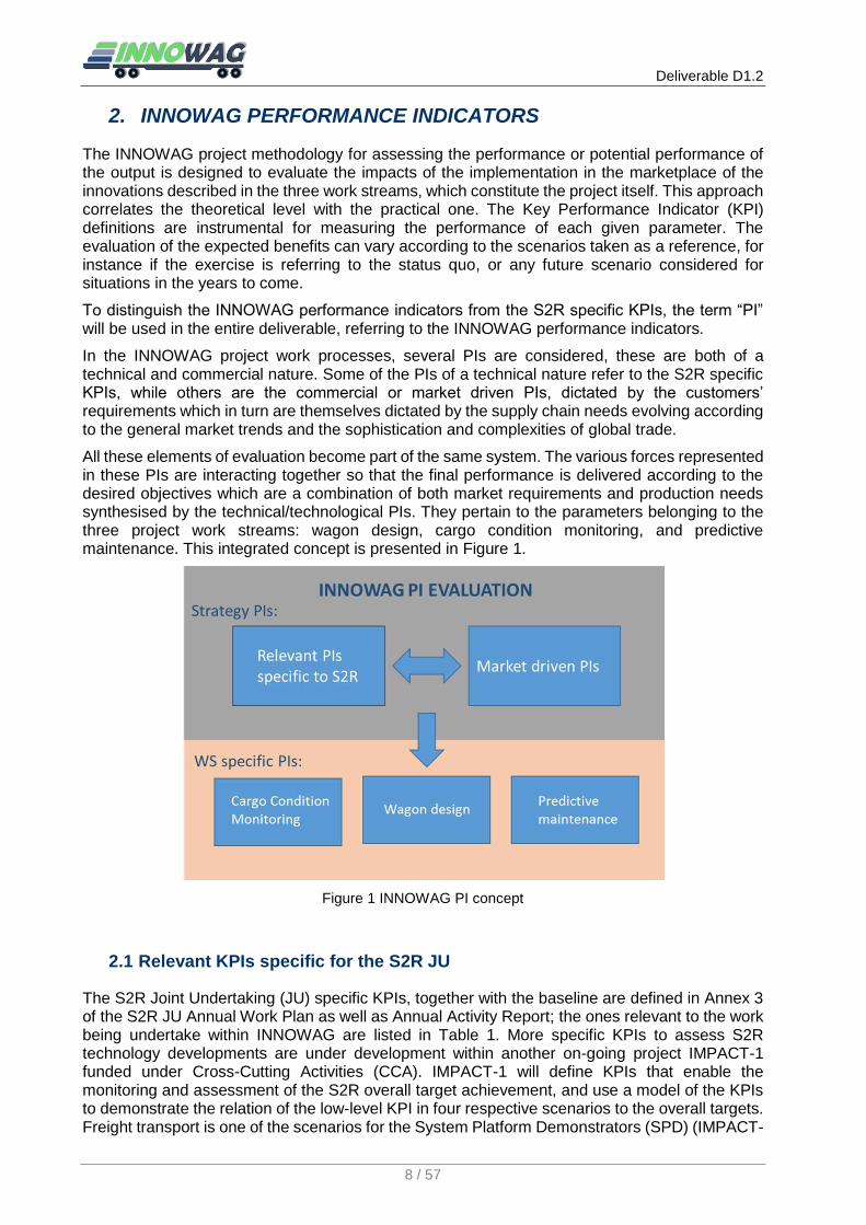
All these elements of evaluation become part of the same system. The various forces represented in these PIs are interacting together so that the final performance is delivered according to the desired objectives which are a combination of both market requirements and production needs synthesised by the technical/technological PIs. They pertain to the parameters belonging to the three project work streams: wagon design, cargo condition monitoring, and predictive maintenance. This integrated concept is presented in Figure 1.
Figure 1 INNOWAG PI concept
2.1 Relevant KPIs specific for the S2R JU
The S2R Joint Undertaking (JU) specific KPIs, together with the baseline are defined in Annex 3 of the S2R JU Annual Work Plan as well as Annual Activity Report; the ones relevant to the work being undertake within INNOWAG are listed in Table 1. More specific KPIs to assess S2R technology developments are under development within another on-going project IMPACT-1 funded under Cross-Cutting Activities (CCA). IMPACT-1 will define KPIs that enable the monitoring and assessment of the S2R overall target achievement, and use a model of the KPIs to demonstrate the relation of the low-level KPI in four respective scenarios to the overall targets. Freight transport is one of the scenarios for the System Platform Demonstrators (SPD) (IMPACT-

Deliverable D1.2
9 / 57
1, 2017). The detailed introductions of the S2R assessment methodology can also be found in Deliverable D9.1 of Roll2Rail (2016).
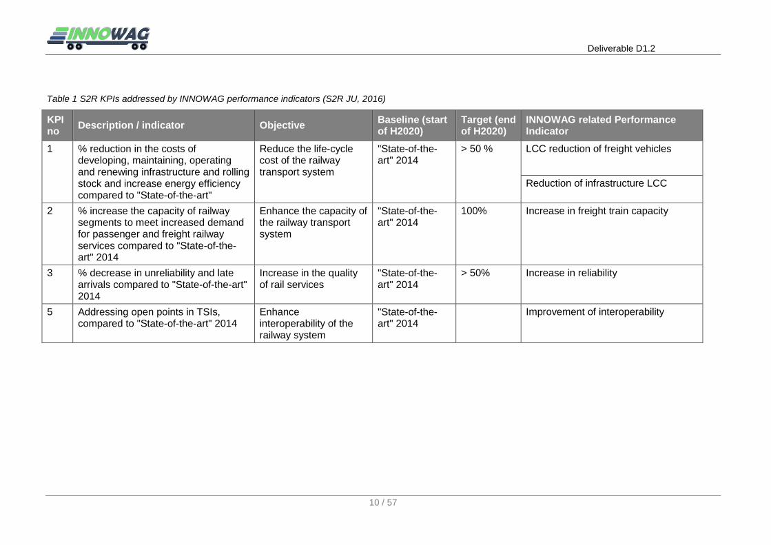
However, to date, the results of IMPACT-1 is not publicly available therefore in this respect, INNOWAG attempts to link its contributions towards the S2R overall target achievement by establishing top-level PIs deriving from the S2R JU specific KPIs. The relationship between them is reported in Table 1. INNOWAG measures towards PIs are analysed below in detail.
To achieve Life Cycle Costs (LCC) reduction of freight vehicles, the following impacts are expected through the innovative measures of the project:
The operational costs of freight vehicles will be reduced due to lower energy consumption, resulting from mass reduction measures.
The manufacturing costs of freight vehicles will be reduced due to material savings, which is enabled by the employment of novel materials and lightweight structures in the vehicle structure design.
The maintenance costs of freight vehicles will be reduced due to optimised maintenance procedures for specific components. Since the predictive models and analysis techniques developed can detect the potential failures before they occur, the frequency of corrective maintenance and inspection measures at workshops will be reduced.
To achieve reduction of infrastructure LCC, the following impacts are expected through the innovative measures of the project:
The impacts on infrastructures will be reduced due to lighter freight vehicles, resulting from mass reduction measures.
The impacts on infrastructures will be reduced due to improved vehicle condition, which is enabled by the deployment of predictive maintenance strategies.
To achieve an increase in freight train capacity, the following impacts are expected through the innovative measures of the project:
The payload-tare weight ratio will be increased due to mass reduction measures.
To achieve an increase in the reliability of freight service, the following impacts are expected through the innovative measures of the project:
The potential damage to cargo during transport will be reduced due to detection and evaluation of recorded condition of key parameters which will drive damage reduction measures. As the measured parameters exceed the corresponding thresholds, alarms will be triggered. Early notification of damage could allow contingency measures to be implemented (e.g., order replacement stock), reducing consequences of damage. Analysis of measurements can also lead to strategies to reduce instance of damage in the future. Hence, delays or cancellations of delivery caused by cargo damages will be minimised.
The potential failures of freight vehicles will be reduced, since the predictive models and analysis techniques developed can detect the faults before they occur thereby minimising delays or cancellations of delivery caused by vehicle failures.
To achieve improvement of interoperability, the following impacts are expected through the innovative measures of the project:
The information obtained by the CCMS can be interchanged in digital form between different operators and applications by designing an appropriate interface for data communication. The data interface will be compliant with the requirements laid down by TAF TSI.
A variety of technologies are involved in INNOWAG. The adapted technologies in the proposed integrated solutions can contribute to the development of a vehicle condition monitoring system (VCMS) due to the synergies between VCMS and CCMS. For instance, CCMS power supply units and communication systems developed in the project are also suitable for an on-board vehicle condition monitoring system.
Deliverable D1.2
10 / 57
Table 1 S2R KPIs addressed by INNOWAG performance indicators (S2R JU, 2016)
KPI no
Description / indicator Objective Baseline (start of H2020)
Target (end of H2020)
INNOWAG related Performance Indicator
1 % reduction in the costs of developing, maintaining, operating and renewing infrastructure and rolling stock and increase energy efficiency compared to "State-of-the-art"
Reduce the life-cycle cost of the railway transport system
"State-of-the-art" 2014
> 50 % LCC reduction of freight vehicles
Reduction of infrastructure LCC
2 % increase the capacity of railway segments to meet increased demand for passenger and freight railway services compared to "State-of-the-art" 2014
Enhance the capacity of the railway transport system
"State-of-the-art" 2014
100% Increase in freight train capacity
3 % decrease in unreliability and late arrivals compared to "State-of-the-art" 2014
Increase in the quality of rail services
"State-of-the-art" 2014
> 50% Increase in reliability
5 Addressing open points in TSIs, compared to "State-of-the-art" 2014
Enhance interoperability of the railway system
"State-of-the-art" 2014
Improvement of interoperability
Deliverable D1.2
11 / 57
2.2 Market driven PIs
Besides PIs linked to the S2R JU specific KPIs, INNOWAG will also consider market driven PIs, which are elaborated in this section for the purpose of enabling the potential benefits of implementing the solutions proposed by the INNOWAG project to be extracted and analysed. The market driven PIs refers to both direct benefits delivering an immediate economic and service result to the customers in terms of quantitative and qualitative dimensions, and indirect benefits associated more with environmental and societal perceptions and behaviours.
To this effect, the most important elements in terms of the positive effects on service performance in the marketplace with respect to the status quo, which are to be measured through PIs that are not covered in the S2R KPIs, are:
Digitalisation
The outputs in the form of digital data from the intelligent monitoring system, will provide real-time information on cargo conditions which permits smooth integration into the customers’ logistics systems. This is facilitated by cargo tracing and conditions monitoring of key parameters, as well as data management solutions. Furthermore, long term collection of condition information over many assets can be used to implement predictive maintenance programmes – for example sensors for recording exposure to shock and vibration by the cargo might also yield information on suspension, wheel, or track condition. In addition to this, the data management solutions dedicated to predictive maintenance programmes can provide comprehensive data of vehicle conditions.
Attractiveness of rail freight transport
Compared to alternative transport modes, telematics and sensor applications are not commonly found on freight trains. Generally, CCMS can increase the attractiveness of rail freight transport by enabling improvement of railway freight service. For instance, the visibility of shipment status, such as its location and condition, will be increased due to web-based logistics application providing up-to-date information to the interested stakeholders, which is enabled through data management and visualisation solutions. Systems developed for freight wagon tracking can be extended to include cargo condition monitoring requirements. These are highly cost sensitive applications and should be used as extensively as possible on each vehicle where fitted.
Moreover, the CCMS envisaged in INNOWAG will resolve the issues caused by sensor wiring and battery-based power supply of a conventional monitoring system, which results in e.g. additional maintenance of the instrumentation and has limited the adoption of CCMS in general to date.
Environmental impact
The novel wagon design considers the environmental requirements, which encourage noise abatement. In addition, reduction of emissions is considered through reducing energy consumption in operation via the lightweight design concept.
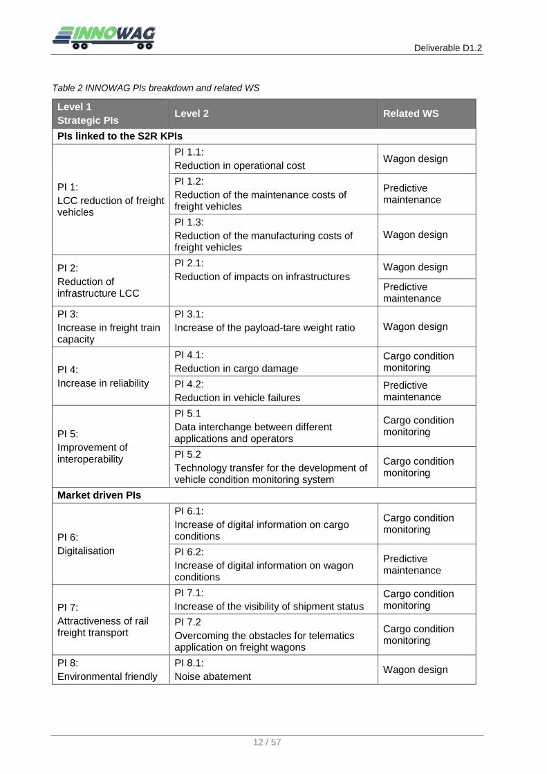
2.3 Relationship between INNOWAG work streams and PIs
So far, the top-level PIs within the INNOWAG project have been identified. These PIs indicate the strategic objectives of the project, which are not easily measured with respect to the tasks within the project. As described in the analysis of the INNOWAG measures towards these PIs, the strategic PIs can be further broken down according to the expected impacts. In this manner, the lower-level PIs are defined, which can be directly linked to each WS. This enables the further breakdown of PIs in each WS in order to achieve the measurable low-level PIs. The following Table 2 shows the defined level-2 PIs and their related WS.
Deliverable D1.2
12 / 57
Table 2 INNOWAG PIs breakdown and related WS
Level 1
Strategic PIs Level 2 Related WS
PIs linked to the S2R KPIs
PI 1:
LCC reduction of freight vehicles
PI 1.1:
Reduction in operational cost Wagon design
PI 1.2:
Reduction of the maintenance costs of freight vehicles
Predictive maintenance
PI 1.3:
Reduction of the manufacturing costs of freight vehicles
Wagon design
PI 2:
Reduction of infrastructure LCC
PI 2.1:
Reduction of impacts on infrastructures Wagon design
Predictive maintenance
PI 3:
Increase in freight train capacity
PI 3.1:
Increase of the payload-tare weight ratio Wagon design
PI 4:
Increase in reliability
PI 4.1:
Reduction in cargo damage
Cargo condition monitoring
PI 4.2:
Reduction in vehicle failures
Predictive maintenance
PI 5:
Improvement of interoperability
PI 5.1
Data interchange between different applications and operators
Cargo condition monitoring
PI 5.2
Technology transfer for the development of vehicle condition monitoring system
Cargo condition monitoring
Market driven PIs
PI 6:
Digitalisation
PI 6.1:
Increase of digital information on cargo conditions
Cargo condition monitoring
PI 6.2:
Increase of digital information on wagon conditions
Predictive maintenance
PI 7:
Attractiveness of rail freight transport
PI 7.1:
Increase of the visibility of shipment status
Cargo condition monitoring
PI 7.2
Overcoming the obstacles for telematics application on freight wagons
Cargo condition monitoring
PI 8:
Environmental friendly
PI 8.1:
Noise abatement Wagon design

Deliverable D1.2
13 / 57
3. CARGO CONDITION MONITORING
Based on the design objectives of WS1, this section deals with the breakdown of the WS1 related PIs, and analyses requirements, specifications as well as constraints of the CCMS to be developed. Since the specific application scenarios are not identified at this stage, the scenario-specific specifications and required features will be defined in the design phase in WP2. Therefore, this section will define the general specifications, based on two relevant application cases. Regarding the required system features, it is focused on the most important functional requirements and operational requirements of the envisaged CCMS, along with the technical restrictions within the context of rail freight vehicles as well as the normative restrictions laid down by the applicable standards and regulations.
3.1 Design objectives
WS1 within the project targets the demonstration of a cargo condition monitoring system (CCMS) on freight trains. The concept behind cargo condition monitoring is to develop an autonomous self-powered wireless sensor system for cargo tracing and condition monitoring of key parameters for critical types of cargo. The up-to-date information on cargo will be presented to the interested stakeholders in a suitable format. The novel technology concepts and the key functions of CCMS will be validated in a relevant TRL 5 environment, i.e. rail freight operations.
In order to formulate the design concept of CCMS, the relevant application cases have to be identified. The cargo to be monitored within WS1 can be divided into two categories: time sensitive low-density high-value (LDHV) goods and dangerous goods. Time sensitive LDHV goods were defined in SPECTRUM (2012):
Goods with a density including packaging (i.e., gross-weight) below 250 kg/m3 are considered as time sensitive LDHV-goods, except live animals, transport equipment, tractors and explosives.
Goods with a density between 250 and 300 kg/m3 and with a value of €0.50 per kg or higher (i.e. trade value, excluding taxes and not the retail value) are considered as time sensitive LDHV-goods.
Perishable goods with a density above 300 kg/m3 and a value below €0.50/kg are also considered as time sensitive LDHV-goods. Examples of this category are dairy products, horticulture products, fresh and frozen fruits/vegetables and meat.
LDHV goods are usually transported by intermodal flat wagons using containers, swap bodies or, reefer containers for perishable goods. The most typical of transport types is to use flat wagons to transport standard containers. This is defined as the first application case, i.e. Case One, where the CCMS monitors the environmental parameters inside containers, such as temperature, humidity, shock, etc.
The classification of dangerous goods transported by rail can be found in Regulations concerning the International Carriage of Dangerous Goods by Rail (RID). The common dangerous goods include explosives, (flammable or toxic) gas, flammable liquid, radioactive material, etc. They can accordingly be transported by tank wagon, closed wagon, tank container, large container, etc. From amongst these, tank wagons carrying gas is defined as the second application case, i.e. Case Two, where the CCMS detects any abnormalities, i.e. gas leak, to avoid potential dangers.
Besides sensors measuring key parameters according to cargo ty.es, the CCMS could track and trace the cargo during the entire journey in order to inform customers and relevant authorities of the location of the consignment. This requires easy access to the generated information by different end-users. In the case of freight wagons, these sensor and telematics applications are essentially restricted by the power supply, as there is no power source on the individual freight wagons, the adoption of batteries being the common solution. However, regular battery replacement causes high maintenance costs and environmental problems connected to their disposal; to resolve these issues and those related to wiring the sensors, the CCMS envisaged by INNOWAG aims at establishing wireless sensor networks (WSN). This means that each sensor
Deliverable D1.2
14 / 57
node is separately powered, however wireless communication raises additional energy demands. With primary batteries being considered as a non-optimal solution, instead, energy harvesting technologies supplying wireless sensor nodes in a WSN will be applied in the INNOWAG system development to exclude the need for regular replacement of batteries. This can be regarded as one of the greatest challenges of the project. Taking into account the limited energy, the on-board monitoring system requires optimised utilisation of energy. Therefore, given a specific application scenario, the priorities of the system functionalities has to be identified so that only the core functionalities will be implemented, depending on the available energy harvested.
Finally, the designed components of the CCMS will be demonstrated and validated by doing tests in specific scenario(s) for each application case simulating a real railway environment, namely by attaching prototype equipment on a container as well as a tank wagon being situated e.g. on a shunting yard. The demonstrator will reach the technical readiness level 5.
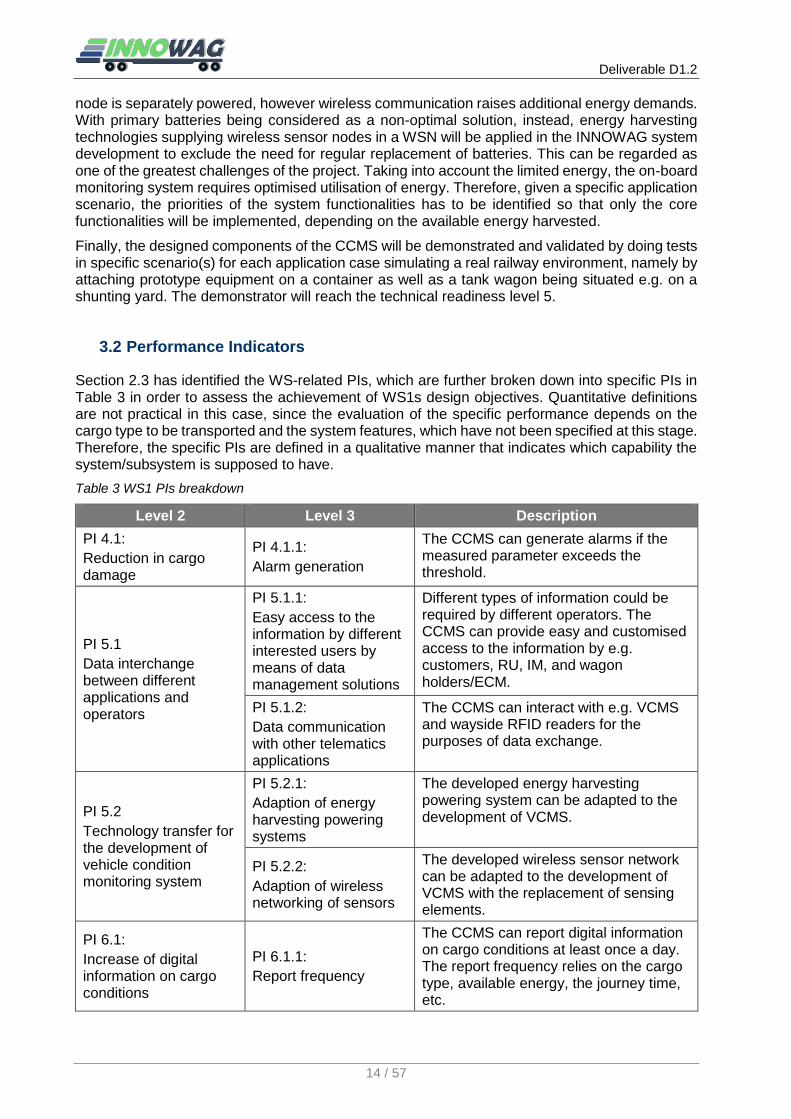
3.2 Performance Indicators
Section 2.3 has identified the WS-related PIs, which are further broken down into specific PIs in Table 3 in order to assess the achievement of WS1s design objectives. Quantitative definitions are not practical in this case, since the evaluation of the specific performance depends on the cargo type to be transported and the system features, which have not been specified at this stage. Therefore, the specific PIs are defined in a qualitative manner that indicates which capability the system/subsystem is supposed to have.
Table 3 WS1 PIs breakdown
Level 2 Level 3 Description
PI 4.1:
Reduction in cargo damage
PI 4.1.1:
Alarm generation
The CCMS can generate alarms if the measured parameter exceeds the threshold.
PI 5.1
Data interchange between different applications and operators
PI 5.1.1:
Easy access to the information by different interested users by means of data management solutions
Different types of information could be required by different operators. The CCMS can provide easy and customised access to the information by e.g. customers, RU, IM, and wagon holders/ECM.
PI 5.1.2:
Data communication with other telematics applications
The CCMS can interact with e.g. VCMS and wayside RFID readers for the purposes of data exchange.
PI 5.2
Technology transfer for the development of vehicle condition monitoring system
PI 5.2.1:
Adaption of energy harvesting powering systems
The developed energy harvesting powering system can be adapted to the development of VCMS.
PI 5.2.2:
Adaption of wireless networking of sensors
The developed wireless sensor network can be adapted to the development of VCMS with the replacement of sensing elements.
PI 6.1:
Increase of digital information on cargo conditions
PI 6.1.1:
Report frequency
The CCMS can report digital information on cargo conditions at least once a day. The report frequency relies on the cargo type, available energy, the journey time, etc.

Deliverable D1.2
15 / 57
PI 7.1:
Increase of the visibility of shipment status
PI 7.1.1:
Type of status information
The end-users can access to the location and condition of their shipment. The type of condition information depends on the cargo type.
PI 7.2
Overcoming the obstacles for telematics application on freight wagons
PI 7.2.1:
Resolving the issue of power supply
The power is merely generated by energy harvesters. Regular battery replacement is not necessary.
PI 7.2.2:
Resolving the issue of wiring
Sensor wiring can be excluded especially outside of vehicles.
3.3 Normative requirements and restrictions
Although there are no standards specifying the design of a CCMS, requirements, especially non-functional requirements, the conditions of operational environment of train-side electronic equipment are laid down in relevant standards and legislation.
The railway interoperability Directive 2008/57/EC lays down a series of essential requirements including safety, reliability and availability, health, environment protection and technical capability. According to this directive, mandatory Technical Specifications for Interoperability (TSIs) were developed by European Union Agency for Railways (EUAR) by which the applicable technical standards are identified to meet the essential requirements on the relevant subsystem or part of subsystem.
The development of on-board monitoring systems should take into account the following TSIs:
Technical Specification for Interoperability relating to the subsystem rolling stock - Freight wagons (WAG TSI)
Technical specification for interoperability relating to the telematics applications for freight subsystem of the rail system in the European Union (TAF TSI)
Regarding the mechanical integration of telematics units on freight wagons, the gauge of rolling stock shall be taken into account. WAG TSI refers to EN 15273-2 to define kinematic gauges. Moreover, WAG TSI sets out environmental conditions to which the designed rolling stock must be tolerant of. These environmental parameters are also applicable to electronic devices to be mounted on rolling stock.
TAF TSI aims to set the technical framework to ensure the efficient interchange of information collected by telematics applications. The requirements are listed accordingly below (TAF TSI, 2014):
Technical compatibility: The essential requirements for Telematics Applications guarantee a minimum quality of service for passengers and carriers of goods, particularly in terms of technical compatibility.
Steps must be taken to ensure:
o that the databases, software and data communication protocols are developed in a manner allowing maximum data interchange between different applications and operators, excluding confidential commercial data,
o easy access to the information for users.
Reliability and availability: The methods of use, management, updating and maintenance of these databases, software and data communication protocols must guarantee the efficiency of these systems and the quality of the service.
Health: The interfaces between these systems and users must comply with the minimum rules on ergonomics and health protection.

Deliverable D1.2
16 / 57
Safety: Suitable levels of integrity and dependability must be provided for the storage or transmission of safety related information.
There are several European standards concerning environment compatibility and installation of monitoring system on railway vehicles. The majority of them are harmonised standards to meet the essential requirements for Interoperability of the rail system. Table 4 lists the relevant standards related to railway applications.
Table 4 Relevant EU standards concerning environment compatibility and installation of monitoring system on railway vehicles
Criteria EU Standards
Structural and mechanical
EN 15273-2 Railway applications — Gauges Part 2: Rolling stock gauge
EN 15827 Railway applications — Requirements for bogies and running gears
EN 13749 Railway applications — Wheelsets and bogies — Method of specifying the structural requirements of bogie frames
Environmental
EN 50125-1 Railway applications - Environmental conditions for equipment - Part 1: Equipment on board rolling stock
EN 50125-3 Railway applications - Environmental conditions for equipment - Part 3: Equipment for signalling and telecommunications
EN 61373 Railway applications — Rolling stock equipment — Shock and vibration tests
Axlebox condition monitoring
EN 15437-2:2012
Railway applications - Axlebox condition monitoring - Interface and design requirements - Part 2: Performance and design requirements of on-board systems for temperature monitoring
Insulation and protective provisions
EN 50124-1 +A2
Railway applications — Insulation coordination — Part 1: Basic requirements — Clearances and creepage distances for all electrical and electronic equipment
EN 50124-2 Railway applications — Insulation coordination — Part 2: Overvoltages and related protection
EN 50153 Railway applications — Rolling stock — Protective provisions relating to electrical hazards
EN 50155 Railway applications — Electronic equipment used on rolling stock
EMC
EN 50121-1 Railway applications — Electromagnetic compatibility — Part 1: General
EN 50121-3-1 Railway applications — Electromagnetic compatibility — Part 3-1: Rolling stock — Train and complete vehicle
EN 50121-3-2 Railway applications — Electromagnetic compatibility — Part 3-2: Rolling stock — Apparatus
Fire protection
EN 50343 Railway applications — Rolling stock — Rules for installation of cabling
EN 50355 Railway applications — Railway rolling stock cables having special fire performance — Thin wall and standard wall — Guide to use

Deliverable D1.2
17 / 57
EN 45545-2 Railway applications — Fire protection on railway vehicles Part 2: Requirements for fire behaviour of materials and components
Reliability
EN 50126-3 Railway applications — The specification and demonstration of Reliability, Availability, Maintainability and Safety (RAMS) ) — Part 3: Guide to the application of EN 50126-1 for rolling stock RAM
EN 50129 Railway applications - Communications, signalling and processing systems - Safety related electronic systems for signalling
EN 50128 Railway applications - Communication, signalling and processing systems - Software for railway control and protection systems
Functional safety EN 50126-1 Railway Applications - The Specification and
Demonstration of Reliability, Availability, Maintainability and Safety (RAMS) - Part 1: Generic RAMS Process
Amongst them, EN 15437-2 specifies the requirements of an onboard axlebox temperature monitoring system, which are currently not mandatory for a CCMS on freight wagons. Considering a CCMS especially for monitoring dangerous goods can also be regarded as a safety related monitoring system, it could be nevertheless subjected to the relevant requirements laid down by this standard. For instance, it requires
Monitoring systems must generate alarms when the monitored parameter exceeds the threshold.
Any defect or abnormality of the monitoring system itself should be informed.
Measurement accuracy
The functional safety must be defined both for hardware and software of the monitoring system, by using the methods prescribed in EN 50126-1 or EN 61508.
The monitoring system must be active during the entire journey.
Alarms must be sent to the train driver.
Apart from standards for railway applications, several industrial standards for electronic equipment and specific for UHF RFID are collected in Table 5.
Table 5 Relevant industrial standards
Criteria Standards
Other relevant industrial standards
EN 61508-1 Functional safety of electrical/electronic/programmable electronic safety-related systems - Part 1: General requirements
EN 61000-4 Electromagnetic compatibility (EMC) - Part 4
IEC 60529 Degrees of protection provided by enclosures (IP Code)
EN 62262 Degrees of protection provided by enclosures for electrical equipment against external mechanical impacts (IK code)
UHF RFID
ISO/IEC 18000-6
Information technology -- Radio frequency identification for item management -- Part 6: Parameters for air interface communications at 860 MHz to 960 MHz
EPC Gen2 EPC Compliant Class-1 Generation-2 UHF RFID Devices Conformance Requirements

Deliverable D1.2
18 / 57
EN 302208 Electromagnetic compatibility and Radio spectrum Matters (ERM) - Radio Frequency Identification Equipment operating in the band 865 MHz to 868 MHz with power levels up to 2 W and in the band 915 MHz to 921 MHz with power levels up to 4 W
ATEX directives
ATEX 95 directive 94/9/EC
Equipment and protective systems intended for use in potentially explosive atmospheres
ATEX 137 directive 99/92/EC
Minimum requirements for improving the safety and health protection of workers potentially at risk from explosive atmospheres
In addition, UIC Leaflet 917-3 provides a technical specification for a standardised interface and defines the mechanism for the information exchange over a Cellular Network (CN) between Mobile Unit (MU) and Communication Server (CS) for railway freight wagon telematics applications.
In terms of the transport of dangerous goods in Case Two, measures for explosion control should be performed. In the European Union, the electronic devices applied in an environment with an explosive atmosphere should be subjected to the ATEX directive.
3.4 Application cases
As mentioned above, the CCMS are essentially dedicated for two application cases, namely
Case One: LDHV goods transported by flat wagons using containers
Case Two: Flammable gas transported by tank wagons
Clearly, the sensor types to be employed depend on the cargo type. The selection of sensors will be achieved according to the specific scenarios in the design phase, since it relies on various factors, such as cargo type, container/tank type, amount of harvested energy, etc. Similarly, other functional modules, e.g. energy harvesting system, wireless communication module, tracking & tracing (T&T) module, cannot be specified in this deliverable. Instead, this section analyses the general specifications, requirements, and restrictions for each system module, based on the proposed application cases.
3.4.1 Case descriptions
3.4.1.1 User
The interest group involved in this case consists of customers/shippers, railway undertakings (RUs), wagon keepers/ECM as well as infrastructure managers (IMs).
As analysed in Deliverable D1.1, shippers’ needs are driven by logistics requirements. They are interested in logistics services enabling the availability of consignment-related real time information, including estimated arrival time, current geolocation, cargo conditions as well as cargo integrity. Their demands are in accordance with the project objectives. Within the context of Case One, INNOWAG plans to focus on:
Measuring environmental conditions inside containers (such as temperature and humidity)
Measuring shocks and vibrations that containers are exposed to.
For Case Two.
Measuring conditions inside tanks (such as temperature)
Detecting gas leak
Additional functionalities of potential interest might be explored, such as:
Deliverable D1.2
19 / 57
Tracking and tracing containers
Measurement of cargo weight
Detecting any intrusion into containers
The cargo information must be presented in an easily understandable manner and be remotely accessible, via a secure web-based application for example.
Railway undertakings are responsible for performing transportation and logistics services. They concern the fleet management and cargo loading and unloading operations that can be optimised respectively by means of T&T and load measurement. From the perspective of RUs, T&T should not only be able to determine the position of freight fleets, but enable the mileage tracking of the individual wagons in order to record travelled distances. In terms of load measurement, the functionality could be achieved in three stages (TIS, 2014):
Whether the wagons are under load
Whether the wagons are overloading
Precise measurement of cargo weight
For RUs, detection of overloading could be enabled by monitoring systems.
Wagon keepers/ECM usually have more interest in vehicle condition monitoring for the purposes of preventing vehicle failures and condition-based maintenance. Such functionalities are out of the project scope in terms of the CCMS to be developed. Nevertheless, the mileage tracking can provide the additional information of wagon status for maintenance management. Weighing sensors could also be used to monitor the condition of suspension components for predictive maintenance.
When it comes to transport of hazardous goods in Case Two, wagon keepers can benefit from any safety related measures like detection of abnormal conditions, which might result in vehicle accidents
The loading status of freight wagons is usually inspected by wayside monitoring systems, for which rail infrastructure managers have a responsibility. The onboard weighing solution could replace conventional wayside equipment so as to reduce operating costs of infrastructure operation. For this purpose, the system could permit precise measurement of wagon load.
When it comes to transport of hazardous goods in Case Two, IMs can benefit from any safety related measures like detection of abnormal conditions, which might result in infrastructure damages.
It is worth mentioning that on the one hand, weighing is demanded by some stakeholders and thus is a relevant aspect of sensor applications in the rail system. On the other hand, viable wayside systems and solutions exist for weighing. In most cases, weighing is performed only when loading/unloading, and it is more likely regarded as a part of a VCMS. Therefore, onboard weighing is a low priority in terms of cargo condition monitoring.
3.4.1.2 Monitoring equipment
As a result of the user analysis, the sensors potentially involved could be as follows.
Case One:
1. Temperature sensors for monitoring the ambient temperature inside containers
2. Humidity sensors for monitoring the ambient humidity inside containers
3. Accelerometers for detecting shock or/and vibration that containers are exposed to,
4. Weighing sensors for accurate measurement of cargo weight
5. Light sensors/reed switches (/other sensor types introduced in D1.1) for intrusion detection.

Deliverable D1.2
20 / 57
Case Two:
1. Temperature sensors for measuring pressured gas temperature
2. Liquid level detection sensors/pressure sensors/gas sensors for detecting gas leak
Apart from sensors, the CCMS should include the following modules for both Case One and Case Two:
1. Energy harvesters for each sensor node
2. Transceivers for wireless communication for each sensor node
3. Other necessary components for each sensor node
4a. T&T module by means of using devices installed on vehicles, such as GNSS equipment and speed sensors
4b. T&T module based on the interaction between train-side RFID tags and wayside RFID readers
4c. T&T module based on radiolocation, using existing mobile network based communication module
5a. Train-to-Ground (T2G) communication module by means of remote communication technologies, such as mobile network
5b. T2G communication module based on the interaction between train-side RFID tags and wayside RFID readers
6. Local data logging using onboard data loggers
7a. Data storage and processing based on a cloud storage platform
7b. Data storage and processing based on a server centre
8a. Data representation based on web technologies
8b. Data representation based on existing commercial software
These are individual capabilities that should be developed with the necessary supporting infrastructure with the potential for the system to be modular so that the infrastructure can support multiple modules, dependant on power and data, cost/value etc.
The CCMS is divided into the onboard unit and IT infrastructure. For Case Two, the ownership of the CCMS is held by the wagon keepers, therefore it is less complicated in comparison to Case One. In Case One sensors are mounted inside/on containers, whereas some components such as vibration energy harvesters, if applied, have to be installed on vehicles - the wagon unit and onboard unit might be owned by different stakeholders and have to interact in different combinations. Moreover, containers might be further transported by other means of transport in the intermodal transport mode. That means the onboard unit should tolerate being carried by other transport types (and perhaps log data during this phase) and work (communicate data and export to ground) when loaded on to train, with the possibility that other transport types be fitted with similar systems to the rail vehicle to access the capabilities of the system on the container. In some cases, the container owners might have their own container imbedded system. Thus, the devices should be as compatible as possible with the existing container imbedded monitoring systems - this means that an open standard protocol, if applicable, should be used for communication in any further development.
Clearly, the INNOWAG solution of the CCMS is not able to resolve all of these issues. The initial idea is to use the energy harvested from the rail environment to power the container-imbedded sensors measuring key parameters, excluding sensor wiring. This technical concept is to be validated in a TRL 5 environment, namely technology validated in relevant environment (industrially relevant environment in the case of key enabling technologies). That means issues of operations and business models are out of the project scope.
Deliverable D1.2
21 / 57
3.4.1.3 Freight fleet
It is well known that wireless energy and data transmission is essentially restricted by the transmission range. Therefore, both the wagon length and the train length are sensitive for the design of the WSN and the energy harvesting system.
For instance, it might be required that the generated alarms should be sent from a wagon to the locomotive. The maximum length of freight trains is commonly defined as 600-750m in most European countries. Given the assumed train length of 600m, the alarm messages could be transmitted over several hundred meters. This requires high-energy consumption, which might not be possible in the case of energy harvesting. Moreover, there is a limitation of the wavelength available for unlicensed radio in Europe (433MHz or 868MHz). Given the limited wavelength, a longer antenna and a suitable installation location is required for efficient transmission. With respect to resource limits and technical restrictions, the railway environment for both Case One and Case Two will be defined as a freight train consisting of a small number of container wagons, not more than three. Nevertheless, the designed solution should be scalable to the realistic dimensions in the context of rail freight transport, with additional energy sources.
The main impact of wagon length on the system is in relation to its effect on the distance of wireless energy and signal transmission. In Case Two, the distance depends on the location of the mechanical interface on the tank for the sensor installation and the installation location of the energy harvesters. In Case One, a flat wagon can carry more than one container - considering the worst case, sensors on the middle container placed on a long wagon can be hardly powered by a vibration harvester installed on an axlebox. The distance could be about 5m in terms of a 60’ flat wagon carrying three 20’ containers. Therefore, the INNOWAG solution of the CCMS is not suitable for a long container wagon exceeding 60’, if the vibration harvesters are employed as the main power generator.
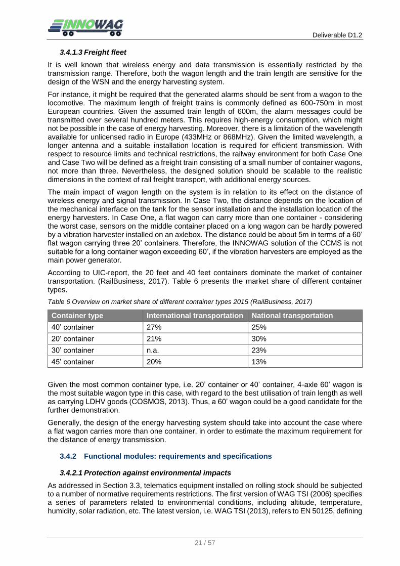
According to UIC-report, the 20 feet and 40 feet containers dominate the market of container transportation. (RailBusiness, 2017). Table 6 presents the market share of different container types.
Table 6 Overview on market share of different container types 2015 (RailBusiness, 2017)
Container type International transportation National transportation
40’ container 27% 25%
20’ container 21% 30%
30’ container n.a. 23%
45’ container 20% 13%
Given the most common container type, i.e. 20’ container or 40’ container, 4-axle 60’ wagon is the most suitable wagon type in this case, with regard to the best utilisation of train length as well as carrying LDHV goods (COSMOS, 2013). Thus, a 60’ wagon could be a good candidate for the further demonstration.
Generally, the design of the energy harvesting system should take into account the case where a flat wagon carries more than one container, in order to estimate the maximum requirement for the distance of energy transmission.
3.4.2 Functional modules: requirements and specifications
3.4.2.1 Protection against environmental impacts
As addressed in Section 3.3, telematics equipment installed on rolling stock should be subjected to a number of normative requirements restrictions. The first version of WAG TSI (2006) specifies a series of parameters related to environmental conditions, including altitude, temperature, humidity, solar radiation, etc. The latest version, i.e. WAG TSI (2013), refers to EN 50125, defining

Deliverable D1.2
22 / 57
the limit values of the environmental parameters. Amongst them, the parameters related to monitoring equipment are presented in Table 7.
Table 7 Environmental conditions related to the installation of monitoring equipment (EN 50125)
Parameters Condition Value / Range
Temperature
Air temperature out of vehicles (class TX)
-40°C to + 50°C
Air temperature within vehicles (class TX)
-40°C to + 60°C
Humidity
Annual mean value ≤ 75 % relative humidity
On 30 days continuous 75 % to 95 % relative humidity
On the other days occasionally 95 % to 100 % relative humidity
Highest absolute humidity 30 g/m3 in tunnels
Solar radiation R1 (low) 700 W/m2
R2 (high) 1120 W/m2
Pollution Dust Class 5S2 according to EN 60721-3-5
Other Lightning, snow & hail, rain
During the benchmark study in the deliverable D1.1, several telematics devices and sensors designed for rolling stock have been investigated. The operation temperature of these devices usually ranges from -40°C to 85°C. This temperature range indicates the maximum/minimum temperature which the device can withstand. The actual operating temperature range is narrower, since electronic devices will suffer severe damage from extreme temperature, especially during charging. The typical range is -30 °C to 60 °C.
In terms of protection against physical intrusion, dust and water, some devices are marked with an IP code, which is defined in IEC 60529. The common levels of IP code are IP67, IP68 and IP69K.
For protection against external mechanical impacts, several devices are marked with IK code, defined in EN 62262, while most of devices are certificated with the relevant IEC standard and EN standard, such as IEC 60068-2-27 and EN 61373. They should have shock resistance up to 30 g.
Taking into account the electromagnetic compatibility, the equipment should be compliant with the relevant standards, such as EN 50121-3-2 and EN61000-4-2.
Especially for Case Two, devices must be authorised under ATEX Zone 1 – 2G (temperature class T4/surface temperature < 135 °C) for areas subject to gas explosions and Zone 21 – 2 D (maximum surface temperature 125 °C) for areas subject to dust explosions.
3.4.2.2 Data acquisition – sensors
Generally, the sensor applications are restricted by the limited harvested energy. The sensors with low priority might not be deployed. Considering that the sample frequency has significant impacts on the power consumption, it has to be defined in the development stage for each type of sensors, with respect to the available energy.
Weighing sensors
To specify the features of weighing sensors, it should take into account the maximum loading weight of wagons and the maximum axle load of 22.5 t. For instance, 60’ container wagons are usually designed for the transport of light goods with the max. loading weight of about 70 t. Thus, the measurement range of weighing is up to 70 t.

Deliverable D1.2
23 / 57
Intrusion detection sensors
For Intrusion sensors reviewed in Deliverable D1.1, door open/close sensors based on reed switches and light sensors can be used to detect intrusion. Therefore, the specification will be detection door open/close event in real-time and with minimal false alarms.
Temperature sensors
In the SPECTRUM project Deliverable D3.3, it was stated that “SPECTRUM service shall cover all commercially available type of reefers suitable to transport goods from -35°C - 25°C”. In addition, the temperature range within/out of rolling stock is presented in Table 7, ranging from -40°C to 60°C. This range can be regarded as the measurement range of the temperature inside containers. According to the benchmark study, this measurement range can be covered by numerous temperature sensors, whilst a high accuracy of ≤ 1°C can be achieved at room temperature (about 25°C). At extreme temperature, the accuracy is in the order of several degrees, normally less than 3°C.
In Case Two, the temperature inside tanks can be several hundreds of degrees, depending on the tank type.
Humidity sensors
In the market, there are sensors able to measure the humidity from 0% to 100%, which was reviewed in INNOWAG deliverable D1.1. Therefore, 0% to 100% should be covered by the sensor measurement range. The accuracy is in the order of several percent relative humidity. In a similar manner, the accuracy gets worse at the extremes.
Vibration & Shock detection sensors
Vibration and shock will be measured via the value of acceleration. In BSI standard (BS EN 14363:2016), the acceleration from vibration in vehicle body is defined in y (lateral) and z (vertical) direction in line with frequency range, which is summarised in Table 8.
Table 8 Acceleration parameters for vibration in vehicle body for freight wagons with bogies, loaded (BS EN 14363:2016)
Parameters Threshold value / range Description
yq,max 3.5 m/s2 (0.35g) Lateral acceleration
zq,max 5.0 m/s2 (0.50g) Vertical acceleration
f 0.4 Hz – 10 Hz Vibration frequency
For convenience, +/-2g is normal for suspended rail vehicle monitoring (one direction has a 1g offset), and bandwidth up to 200Hz. For different types of goods, there are specific thresholds and ranges in order to keep the goods safe. However, vibration monitoring of cargo is a low priority, since sufficient measures can be taken to minimise the vibration suffered by cargo during transport. Instead, the major commercial sensor and telematics applications on freight wagons merely concern shock.
For shock, Shust (2007) stated that “Half-sine shocks of 10g peak (20 – 50 msec). If on car strength members, local resonances can raise levels to: 15g (100-150 Hz) and 50g (200-500 Hz)”. On the other hand, the ViWaS (2015) project conducted interviews with potential users of telematics applications with regards to the requirements and specifications of shock detection sensors applied on freight wagons. The sensor should be a three-axle accelerometer with selectable thresholds for shock detection. The maximal shunting shock is usually less than 10g. Nevertheless, the accelerometers integrated in telematics boxes can commonly cover the acceleration up to 16g. Besides, certain sensors can measure acceleration in the order of 100g.
The noise spectral density could be in the order of few mg/√Hz, depending on the measurement range.

Deliverable D1.2
24 / 57
Gas leak
As an example of gas detections, gas sensor from MICROSENS (2017) can detect gas including CO (1 – 1000ppm), C2H5OH (10 – 500ppm), H2 (1 – 1000ppm), NH3 (1 – 500ppm), CH4 (>1000ppm). However, the substance and required detection of concentrations may vary for different types of gas goods, in line with standards or regulations such as HSE and BSI.
Some typical alarm levels of gas exposure are summarised (NRL 2013 and HSE 2013) and listed below in Table 9.
Table 9 Alarm levels for various gases
Gas type Exposure limits Reference
Pentafluoroethane (CF3CHF2)
1000 ppm Safety data sheet refrigerant R410A (NRL 2013)
Chlorine (Cl) Low: 1-5 ppm
High: 3-15 ppm HSG40 (HSE 1999b)
Hydrogen sulphide (H2S) Low: 10 ppm
High: 15 ppm
HSE Offshore Information Sheet No. 6/2009 (HSE 2009)
Hydrogen sulphide (H2S) Low: 10 ppm
High: 15 ppm BS EN ISO 10418 (2003)
Carbon monoxide (CO) Low: 50 ppm
High: 100 ppm BS EN 50291-1 (2010)
Carbon monoxide (CO) Low: 100 ppm
High: 200 ppm
USA-based Interscan website (Interscan, 2012)
Chlorine (Cl) Low: 0.5 ppm
High: 1 ppm
Ethylene oxide (C2H4O) Low: 2-2.5 ppm
High: 5 ppm
Formaldehyde (CH2O) Low: 1 ppm
High: 2 ppm
Hydrogen chloride (HCl) Low: 1.9 ppm
High: 4-4.5 ppm
Hydrogen sulphide (H2S) Low: 10-20 ppm
High: 20-50 ppm
Sulphur dioxide (SO2) Low: 2 ppm
High: 5 ppm
However, gas detection might be complicated by the aerodynamic effects of vehicle motion. The leak rate that would be detected in static air might be too diluted to detect in moving air. As an alternative to gas sensors, liquid level sensors or pressure sensors can be deployed to measure conditions inside tanks. The inner pressure depends on the type of transported goods and tanks, usually ranging from several bar up to 30 bar.
Passive RFID tag antenna-based sensors
Besides conventional sensors, passive RFID tag antenna-based sensors and systems are considered as an integrated solution for taking various measurements, via local wireless communication and using self-powering systems. This technology was introduced in the INNOWAG deliverable D1.1. Zhang et al (2017) reviewed the passive RFID tag antenna-based sensors and systems for condition monitoring, which includes sensing of strain, crack, corrosion and relevant feature extraction techniques. Arcadius et al (2017) also summarised the capability
Deliverable D1.2
25 / 57
of RFID sensors for chemical (pH value, Sulfate, chlorine, etc) and physical (Temperature, humidity, precipitation, wind speed and direction, solar irradiation, velocity, etc) sensors working as Internet of things-based sensor network.
Previous detailed experiences and expertise on the application of RFID sensors were achieved at UNEW and will feed into further work. Zhang, Tian & Zhao (2017) developed an ultra-high frequency (UHF) passive RFID sensor (around 915MHz) system for crack detection and showed feasibility for condition monitoring. With a dedicated design of RFID tag, the measurement of backscattered power and phase at the reader side was carried out using a ThingMagic Mercury xPRESS platform. Zhang, Tian & Zhao (2016) designed a 3-D antenna sensor to work on the surface of a protective coated steel sample. Sweep-frequency measurements were applied for an analogue identifier with principal component analysis (PCA) to overcome the multiple influences from reader-tag orientation, distance, and environment. In addition to corrosion detection, low frequency (LF) RFID (around 125 kHz) was also implemented (Sunny et al, 2016). Two features were selected, namely static (Max (A)) and transient (PVmax(∆A/∆t)) response to determine permeability and conductivity changes respectively with corrosion exposure. Zhang et al (2016) implemented high frequency (HF) RFID at 10-13 MHz band for measuring variation of lift-off caused by corrosion.
Generally, RFID sensors have a dedicated antenna design for indirectly sensing. This means no additional sensors are needed, and no power on the tag-side is required. The critical issue of such technology is that the tag should be attached to the conductive material. Thus, RFID sensors are commonly used for monitoring structure integrity. In the case of cargo condition monitoring, their applications are significantly restricted.
3.4.2.3 Data acquisition – Identification technologies
Identification technologies within the context of the railway sector originally refers to the identification of vehicles. This is especially necessary as part of wayside monitoring systems, and it can be achieved by RFID technologies and image processing techniques. In the context of onboard cargo condition monitoring, this term refers to the identification of goods that should cover the following aspects:
Identifying consignment information (including how many units, type of cargo, source and destination, tracing data, etc.)
Associating consignment information with the containers/wagons
Linking the monitoring units mounted on the containers/wagons to the consignment
In this way, the obtained data will be correctly allocated to the cargo, and then be presented to its shipper. Therefore, the link between consignment and loading units (i.e. containers/wagons) as well as the link between loading units and monitoring units has to be established. The former could be achieved by the consignees’ logistics system, while the latter relies on the unique ID-numbers of the monitoring units, which are directly linked to the corresponding container/wagon numbers.
3.4.2.4 Data acquisition – tracking & tracing technologies
Several T&T technologies have been identified in the INNOWAG deliverable D1.1, including satellite navigation, radiolocation, dead reckoning, RFID technology and localisation based on track signalling equipment. To avoid interacting with track signalling equipment, the design of the T&T module within the project will consider the solutions based on commercially available hardware. The benchmark study indicates that most telematics applications on railway vehicles employ GNSS modules as the solution of geolocalisation and vehicle tracking. In the case of using GNSS modules, the following issues that mainly rely on energy supply and customers’ demands have to be specified:
The frequency of location data obtained by the GNSS module
The frequency of location data transmission to cloud / a back-office

Deliverable D1.2
26 / 57
In comparison to GNSS equipment, radiolocation and the RFID based solution requires lower energy consumption. If a mobile network is applied for remote communication, it can also be used for radiolocation - this means that no additional hardware would be needed. The drawback of this technology is low localisation accuracy. As an alternative, RFID technology can be used for both T2G communication and T&T as well. On the one hand, train-side RFID tags can be self-powered, on the other hand, the localisation accuracy purely depends on the amount of wayside RFID readers installed.
3.4.2.5 Power supply
As stated in the INNOWAG deliverable D1.1, solar, vibration and RF are the most viable potential energy source within the railway environment. Regarding the intrinsic properties of the energy harvesters, vibration energy harvesting units have to be located on the place with high vibrations, such as the axle box, which is also the most demanding in terms of environmental conditions and distance from the cargo sensor. In a similar manner, solar energy harvesters are best suited to being located on the upper part of the vehicle. Both are restricted to the installation location. Nevertheless, they have the capability to harvest sufficient energy to power the monitoring system. By contrast, the RF harvesters, i.e. RF tags, can be placed on any place within/outside vehicles. However, they require a local RF source, i.e. RF readers, which must be powered either by batteries or other energy harvesters. Consequently, the solutions of power supply could be:
Vibration energy harvesters mounted on/inside the axle boxes to power RF readers, which communicate and power the sensors equipped with RF tags placed in/on containers or other parts in vehicles via RF signal
solar energy harvesters mounted on the upper part of vehicles to power RF readers, which communicate and power the sensors equipped with RF tags placed in/on containers or other parts in vehicles via RF signal
Combination of the cases above
However, the required reader-to-tag communication range is likely to be not less than 7.5 metres, therefore passive ultra-high frequency (UHF) RFID should be used in order to achieve that communication distance, as indicated by the communication range of RFID technologies shown in Table 10 (if active RFID is selected, there will be requirement for power supply on the side of RF tags to enable continuous communication with the readers).
Table 10 Communication range for passive/active RFID at varied operation frequency
Type of RFID
LF 125-134 kHz HF 13.64 MHz UHF 865-960 MHz
Passive 1-10 cm 1-100 cm 5-6m (30m+ in ideal conditions)
Active N.A. N.A. 100m+
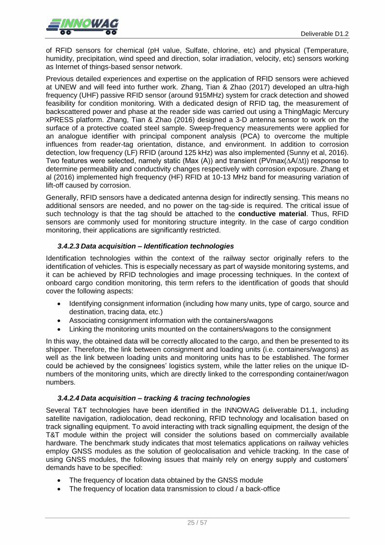
As mentioned, if only vibration energy harvesters are applied, energy transmission is required to cover a distance of about 5m in terms of wagons with a length of up to 60’ in the worst case scenario. This is a great challenge for passive RFID and should be tested in the further design phase. On the other hand, the minimum required distance is about 0.5 m, where RF tags are placed on a container directly above axlebox. For solar energy harvesters, the installation location has more flexibility. As an example, VTG has equipped their wagon fleet with telematics units powered by solar energy, see Figure 2. Based on harvested energy, this telematics unit contains GPS localisation, GSM based data transmission and WPAN module for external sensor connection.
The main features of the solar and vibration energy harvesters are power output and voltage output. The former is based on operational conditions, while the latter is normally defined as 5 V. A specification example of a vibration energy harvester is presented in Table 11.
Deliverable D1.2
27 / 57
Figure 2 Telematics units equipped by VTG’s wagon fleet (left: http://www.keketui.com/p/30Lzu3.html ; right: http://nexiot.ch/globehopper )
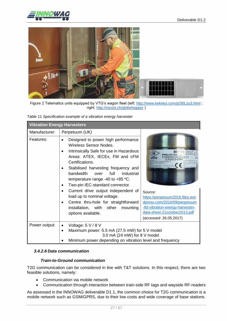
Table 11 Specification example of a vibration energy harvester
Vibration Energy Harvesters
Manufacturer: Perpetuum (UK)
Source:
https://perpetuum2016.files.wor
dpress.com/2016/09/perpetuum
-ltd-vibration-energy-harvester-
data-sheet-21october2013.pdf
(accessed: 26.05.2017)
Features: Designed to power high performance
Wireless Sensor Nodes.
Intrinsically Safe for use in Hazardous
Areas: ATEX, IECEx, FM and cFM
Certifications.
Stabilised harvesting frequency and
bandwidth over full industrial
temperature range -40 to +85 ºC.
Two-pin IEC-standard connector.
Current drive output independent of
load up to nominal voltage.
Centre thru-hole for straightforward
installation, with other mounting
options available.
Power output: Voltage: 5 V / 8 V
Maximum power: 5.5 mA (27.5 mW) for 5 V model 3.0 mA (24 mW) for 8 V model
Minimum power depending on vibration level and frequency
3.4.2.6 Data communication
Train-to-Ground communication
T2G communication can be considered in line with T&T solutions. In this respect, there are two feasible solutions, namely:
Communication via mobile network
Communication through interaction between train-side RF tags and wayside RF-readers
As assessed in the INNOWAG deliverable D1.1, the common choice for T2G communication is a mobile network such as GSM/GPRS, due to their low costs and wide coverage of base stations.

Deliverable D1.2
28 / 57
With respect to energy demands, the frequency of data transmission should be considered at the design stage.
In the railway industry, RFID is traditionally used for vehicle identification. In the case of data communication, the RF tags should be able to transmit measured data to the readers installed alongside the track, when the train passes by the readers. J. Qian et al. (2011) used an integrated passive UHF RFID tag with an embedded temperature sensor attaching to train axles to measure axle temperature. Over the pass-by time, the tag received the energy from the reader, measured the axle temperature, saved the value, and transmitted it to the reader. This system was successfully tested at a speed ≤ 400km/h. It should be noted, this depends on the amount of transmitted data.
Intra-train communication
As the train formation cannot be specified, the required data communication for both application cases could include vehicle-to-vehicle (V2V) communication, vehicle-to-locomotive (V2L) communication, and intra-vehicle communication. It is more likely that each vehicle has a complete communication system, consisting at least of a WSN for data communication between sensors and a T2G module. If V2L communication is necessary, for instance, for the purposes of sending alarm messages to the train driver, a relay node is thus required for each wagon. Regarding the train length, relay nodes might not be able to send data directly to the locomotive. Instead, V2V communication is involved for multi-hop communication to relay the messages to the locomotive. From the perspective of energy consumption, the best WSN architecture is not clear so far. The WSN must ensure the communication of sensor data with a good trade-off between power consumption and data delivery performance.
As mentioned, the wagon length and the train length are significant for the design of a WSN. The length of standard container flat wagons ranges from 40’ (about 12 m) to 104’ (about 32 m). With respect to energy harvesting systems, wagons defined in Case One could have a length of up to 60’ (about 18 m). It means the designed WSN should be suitable for this communication range, at least half of the length of wagon (9 metres). For Case Two, the length of common tank wagons is also included in this range.
To design a WSN, existing industrial standards are considered, which have been presented in the INNOWAG deliverable D1.1. The benchmark also shows that rail freight wagons have been interested in using IEEE 802.15.4 compatible transceivers. Especially in Germany, the practice group, named as the Technical Innovation Circle for Rail Freight Transport (TIS), consisting of several companies in rail freight industry such as DB Schenker, SBB Cargo, VTG, etc., is attempting to standardise wireless communication between sensors and telematics devices using IEEE 802.15.4 compatible transceivers operating in the 2.4 GHz ISM band, in order to allow mixing and matching sensors and telematics devices from different vendors (TIS, 2017). The IEEE 802.15.4 based application such as ZigBee is suitable for intra-vehicle communication, and it enables multi-hop communication. However, it might exhibit critical problems when applied on a long train (S.M. Rakshit et al, 2012). Nevertheless, this standard is considered as a good candidate in the case of the INNOWAG demonstrator.
Regarding the wireless connection between vehicles, the wireless sensor networks should provide mechanisms for minimising interference, data loss and latency. Additionally, it should support time synchronisation across the network deployed on a train.
Apart from conventional WSNs, RFID provides wireless communication and identification between a reader and a tag, enabling the formation of a WSN. In RFID-based sensor networks, a commercial or developed sensor is connected to a control unit to gather the data and that data is transmitted by the tag to the reader wirelessly. In this case, the sensor and controller require power supply from energy harvesting and the tag can be passive (require no power supply, but shorter communication range) or active (require power supply but longer communication range). A Commercial RFID tag and reader can be used in this case. For example, RFID tag with 16k or 800 bit memory is provided by an RFID Sensor System (2017). In addition, such an RFID based wireless sensor network is commercially available on the market. Melexis EVB90129 evaluation
Deliverable D1.2
29 / 57
board (Melexis (2017) is an example available at UNEW, including pass sensor tag for sensor control and communication without a battery, sensor control via microcontroller and memory are powered with a battery on board, electromagnetic field powered or external power supply with low power consumption. Three types of sensors are integrated, light, temperature and trimmer sensors.
Particularly for RFID, the communication range between sensor nodes (reader-to-tag reading range for RFID) should be not less than half of the length of wagon (9 metres) in the situation of one reader for each wagon. Alternatively, more than one reader is required to be installed in each wagon to cover the sensing and data collection within the wagon.
3.4.2.7 Data processing, storage and representation
With regard to the limited energy, the measured raw data should be processed by an integrated microcontroller in each sensor node before being transmitted, on the basis that the energy demand of data transmission is more than local processing. Particularly in the case of cargo condition monitoring, basic data processing is sufficient for detecting if the measured parameter will exceed the specified threshold. These abnormal conditions should be reported as alarm messages, especially in Case Two which deals with safety related monitoring.
In the case of RFID sensors, the data processing must be dedicated to the measurement objectives. For instance, in crack and corrosion detection via RFID, backscattered power and phase, resonant frequency and impedance are key parameters to characterise the defect. In conjunction with the kernel principle component analysis (PCA) based feature extraction method, the (open) crack can be quantified in terms of crack depths where mm-resolution is achieved (Zhang et al., 2017).
The processed data will be transmitted either to a cloud storage platform or to a server centre. The issues on IT infrastructure will be specified at the design stage, taking into account data security and data interface.
The data representation will be based on an existing platform, which should be remotely accessible. The data must be able to be presented in easily understandable manner.
3.5 Summary of Requirements
This section provides an overview of the functional requirements, operational requirements, and restrictions on the system design. These requirements and restrictions are summarised from the analysis above and complemented by the project partners with their practical experiences.
On the one hand, a variety of technologies are available for an integrated solution of the envisaged CCMS, on the other hand, with regards to the limited resources and technical restrictions, not all sensors and telematics applications can be implemented. Therefore, MoSCoW prioritisation method is used to define the requirements with the priority. The requirements with high priority must be achieved in the project duration.
The term MoSCoW refers to four prioritisation categories:
MUST have: must be achieved within project duration
SHOULD have: should be implemented, may not be achieved within project duration
COULD have: desirable, not necessary, be planned as an optional function, if time and resources permit implementation
WON’T have: not to be planned
Considering this prioritisation approach, the system requirements were further summarised within Table 12.
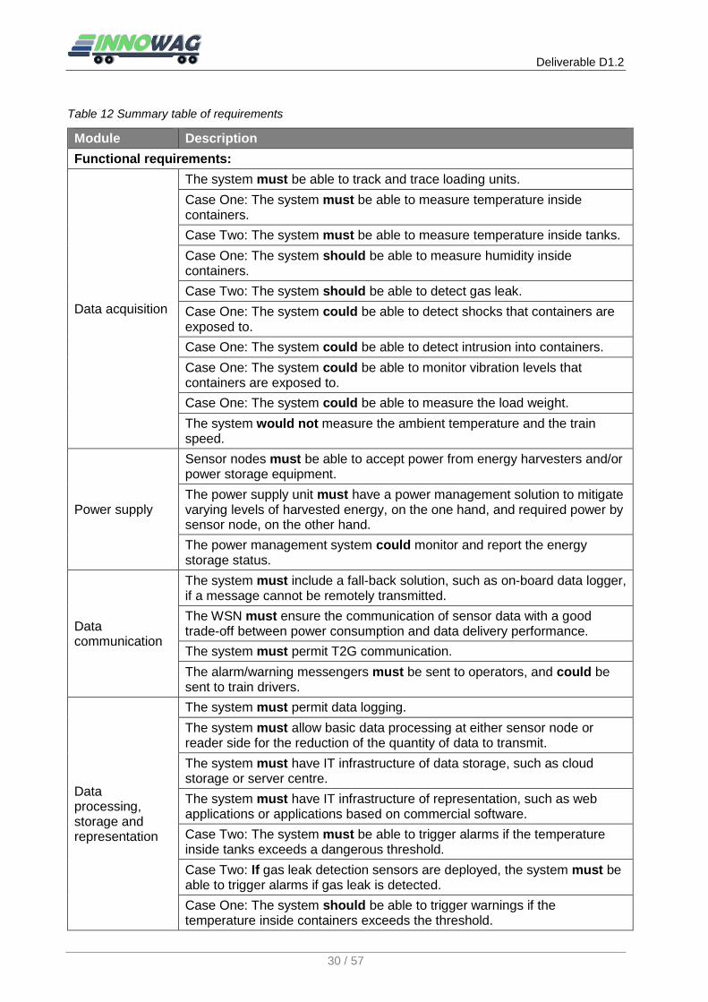
Deliverable D1.2
30 / 57
Table 12 Summary table of requirements
Module Description
Functional requirements:
Data acquisition
The system must be able to track and trace loading units.
Case One: The system must be able to measure temperature inside containers.
Case Two: The system must be able to measure temperature inside tanks.
Case One: The system should be able to measure humidity inside containers.
Case Two: The system should be able to detect gas leak.
Case One: The system could be able to detect shocks that containers are exposed to.
Case One: The system could be able to detect intrusion into containers.
Case One: The system could be able to monitor vibration levels that containers are exposed to.
Case One: The system could be able to measure the load weight.
The system would not measure the ambient temperature and the train speed.
Power supply
Sensor nodes must be able to accept power from energy harvesters and/or power storage equipment.
The power supply unit must have a power management solution to mitigate varying levels of harvested energy, on the one hand, and required power by sensor node, on the other hand.
The power management system could monitor and report the energy storage status.
Data communication
The system must include a fall-back solution, such as on-board data logger, if a message cannot be remotely transmitted.
The WSN must ensure the communication of sensor data with a good trade-off between power consumption and data delivery performance.
The system must permit T2G communication.
The alarm/warning messengers must be sent to operators, and could be sent to train drivers.
Data processing, storage and representation
The system must permit data logging.
The system must allow basic data processing at either sensor node or reader side for the reduction of the quantity of data to transmit.
The system must have IT infrastructure of data storage, such as cloud storage or server centre.
The system must have IT infrastructure of representation, such as web applications or applications based on commercial software.
Case Two: The system must be able to trigger alarms if the temperature inside tanks exceeds a dangerous threshold.
Case Two: If gas leak detection sensors are deployed, the system must be able to trigger alarms if gas leak is detected.
Case One: The system should be able to trigger warnings if the temperature inside containers exceeds the threshold.

Deliverable D1.2
31 / 57
Module Description
Case One: The system should be able to trigger warnings if the humidity inside containers exceeds the threshold.
Case One: If intrusion detection sensors are deployed, the system must be able to trigger warnings in the case of intrusion.
Case One: If shock sensors are deployed, the system should be able to trigger alarms if the detected shock exceeds the threshold.
Case One: If weighing sensors are deployed, the system must be able to detect load status (load/unload).
Case One: If weighing sensors are deployed, the system should be able to trigger warnings in the case of overloading
Case One: If weighing sensors are deployed, the system could be able to present the values of weight immediately during loading / unloading process of cargo.
Operational requirements
System level
Each monitoring unit must have a unique ID that allows the link between the monitoring units and loading units.
The system should permit the user (transport operator) inputting changeable data (such as cargo consignment information (how many units, type of cargo, source and destination, tracing data, etc.) in order to establish the link between consignment and loading units.
Data acquisition
The sensor nodes must have sleep mode in regular conditions in order to reduce the power demand. Some flags or triggers will be defined to wake up.
The WSN must be scalable by means of adding or removing sensor nodes from the network
A sensor node should be able to interface multiple types of sensors.
Selected sensors should be factory calibrated or easy to calibrate by maintenance personnel.
The system should permit the customisable configuration of thresholds and sampling rates.
The detected event such as exceeding thresholds could be recorded with geolocalisation and timestamp.
Power supply
The energy harvesting units must be installed on the suitable places according to the intrinsic properties thereof.
The power supplied by the energy harvesting units should be sufficient for meeting the necessary operating conditions of the sensor nodes and sensors (e.g. duty cycle, sampling rates, data transmission frequency etc.).
Data communications
The system must permit a configurable data transmission frequency for the purposes of the optimal use of energy.
If RFID nearfield communication solution is applied, data transmission between tags and readers must be able to work at normal operational speeds.
If inter-vehicle communication is applied, the WSN solution could be scalable to a long train.
Data processing, storage and representation
The data must be able to be presented in easily understandable manner and be remotely accessible by different stakeholders
Data security and integrity should be guaranteed.
The detected events could be recorded with geolocalisation and timestamp.

Deliverable D1.2
32 / 57
Module Description
Restrictions:
System level
The system installed on flat wagons should be compatible with the current maintenance procedures of such wagons.
Enclosures and electronics should be robust against environmental impacts, such as water, dust, dirt, vibration, etc., during the service life, being compliant with the applicable standards and regulations.
The system should have no detrimental effect on the train equipment, being compliant with normative requirements.
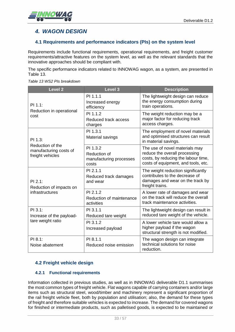
Deliverable D1.2
33 / 57
4. WAGON DESIGN
4.1 Requirements and performance indicators (PIs) on the system level
Requirements include functional requirements, operational requirements, and freight customer requirements/attractive features on the system level, as well as the relevant standards that the innovative approaches should be compliant with.
The specific performance indicators related to INNOWAG wagon, as a system, are presented in Table 13.
Table 13 WS2 PIs breakdown
Level 2 Level 3 Description
PI 1.1:
Reduction in operational cost
PI 1.1.1
Increased energy efficiency
The lightweight design can reduce the energy consumption during train operations.
PI 1.1.2
Reduced track access charges
The weight reduction may be a major factor for reducing track access charges.
PI 1.3:
Reduction of the manufacturing costs of freight vehicles
PI 1.3.1
Material savings
The employment of novel materials and optimised structures can result in material savings.
PI 1.3.2
Reduction of manufacturing processes costs
The use of novel materials may reduce the overall processing costs, by reducing the labour time, costs of equipment, and tools, etc.
PI 2.1:
Reduction of impacts on infrastructures
PI 2.1.1
Reduced track damages and wear
The weight reduction significantly contributes to the decrease of damages and wear on the track by freight trains.
PI 2.1.2
Reduction of maintenance activities
A lower rate of damages and wear on the track will reduce the overall track maintenance activities.
PI 3.1:
Increase of the payload-tare weight ratio
PI 3.1.1
Reduced tare weight
The lightweight design can result in reduced tare weight of the vehicle.
PI 3.1.2
Increased payload
A lower vehicle tare would allow a higher payload if the wagon structural strength is not modified.
PI 8.1:
Noise abatement
PI 8.1.1
Reduced noise emission
The wagon design can integrate technical solutions for noise reduction.
4.2 Freight vehicle design
4.2.1 Functional requirements
Information collected in previous studies, as well as in INNOWAG deliverable D1.1 summarises the most common types of freight vehicle. Flat wagons capable of carrying containers and/or large items such as structural steel, wood/timber and machinery represent a significant proportion of the rail freight vehicle fleet, both by population and utilisation; also, the demand for these types of freight and therefore suitable vehicles is expected to increase. The demand for covered wagons for finished or intermediate products, such as palletised goods, is expected to be maintained or
Deliverable D1.2
34 / 57
increased, whereas the demand for ordinary open wagons is expected to decrease. The demand for hopper wagons for bulk minerals, agricultural products and powders is expected to be maintained or increased. The types of wagons with structures above the main frame (that is those other than flat wagons) offer a greater opportunity for lightweighting due to the more extensive body structures.
The majority of the current freight rolling stock is being dominated by the Y-series type of bogies. Other types are also present but less numerous, and generally referred to as ‘3-piece’ bogies. These are more widely used in the USA, Canada, China and Russia and are generally not a favoured option on EU track because of their relatively bad ride quality and high unsprung mass. On the other hand, there are other types of bogies termed track-friendly (TF), which use technology originally developed for passenger vehicle applications, for example viscous dampers rather than coulomb friction damping to improve the ride performance. These are however often considered too expensive to buy and maintain, therefore they are not yet widely used for freight applications. The focus is therefore on the development of bogie concepts that fulfil the role and functional requirements of the Y-series type of bogie, which can be found in a very large numbers and range of configurations (and under different names). The main variations concern:
the axle wheelbase, either 1.8 or 2m and
the primary spring (spring characteristics) and Lenoir link arrangement.
However, the focus of the vehicle design within this project is on weight reduction rather than specifically targeting reduction in track damage directly, or improving ride quality, although the possibility of incorporating further suspension developments in the future will not be ruled out.
4.2.1.1 Environmental requirements
The product will be designed according to UIC, EN, ISO, TSI, etc. regulations such that its environmental impact in the manufacturing and exploitation stage are within acceptable limits and consistent with best practice. Starting with the design stage, all the measures needed to minimise all kinds of influences on the environment will be considered, especially where materials which are different and non-metallic are used, which are not currently common practice. Particular attention is to be paid to the issues related to recycling and disposal of some of the candidate materials, such as composites.
4.2.1.2 Constructive, functional, and other types of requirements
The wagon manufacturing must observe all the requirements specified in the graphic and written documentation of the manufacturer, set up in accordance with the current requirements specified in the company regulations, in the product regulations, or in the current national and international regulations. This includes all requirements for ensuring that traceability and accountability can be established for all items constructed.
Aerodynamic requirements
Aerodynamic requirements for trains have been addressed in the SUSTRAIL project. Generally, the aerodynamic resistance increases as a quadratic function of the train speed, which results in a high-energy consumption especially at high speeds. Thus, most train aerodynamics research paid attention to high speed passenger trains. Although empty freight trains usually travel at a maximum of 120 km/h, and loaded ones at a maximum of 100 km/h, the aerodynamic resistance of freight trains should not be neglected. In contrast to passenger trains, the design of freight trains has hardly taken into account aerodynamic features. To reduce aerodynamic drag, several design measures have been proposed in SUSTRAIL (2012):
Smooth sides and Top
Bogie fairings
Smooth underframe
Covering hoppers
Streamlining the load

Deliverable D1.2
35 / 57
Lengthening vehicle
Reducing inter-vehicle gaps
For specific wagon types, other measures for the reduction of the aerodynamic resistance could be carried out. In the case of open hopper wagons, for instance, the resistance can be reduced by about 20% by covering hoppers. However, such a cover is impractical in a regular operation; instead, a fixed grid of vertical sheet metal strips in the load opening can achieve a resistance reduction of about 10% with a significant simpler design and fewer operational constraints and complicatonis. The load can easily fall through the grid so that this measure has no negative influence on bulk loading (R. Shoeib, M. Hecht, 2013). Also, freight trains often consist of different wagon types, which makes it difficult to determine the overall aerodynamic characteristics of a train, especially as it will be different for different combinations of vehicles. It is also difficult therefore to evaluate the benefits relative to the impact of the aerodynamic features on the construction, operating and maintenance costs of individual vehicles.
Noise requirements
The UIC (2016) reports on the current noise situation in Europe, EU policy and legislation as well as noise control strategy of the railways. From the perspective of legislation, the Commission Regulation 1304/2014 referred to NOI TSI sets out noise limit values for new rail vehicles in addition to renewed or upgraded wagons. The identified critical parameters of noise are
Stationary noise
Starting noise
Pass-by noise
Drive’s cab interior noise
The limit values differ according to the categories of rolling stock. For freight wagons, limit values for pass-by noise are relevant, and listed in Table 14.
Table 14 Limit values for pass-by noise (NOI TSI, 2014)
Category of the rolling stock subsystem LpAeq,Tp (80 km/h) [dB] LpAeq,Tp (250 km/h) [dB]
Electric locomotives and OTMs with electric traction
84 99
Diesel locomotives and OTMs with diesel traction 85 n.a.
EMUs 80 95
DMUs 81 96
Coaches 79 n.a.
Wagons (normalised to APL = 0,225) (*) 83 n.a.
(*) APL: the number of axles divided by the length over the buffers (m-1)
These requirements are specified for freight wagons equipped with cast iron brake blocks. If, during renewal or upgrading of a wagon, a wagon is being equipped with composite brake blocks and no noise sources are added to the wagon under assessment, then it shall be assumed that the requirements of these limit values are met without further testing (NOI TSI, 2014).
Other policies at EU level are UIC (2016):
Noise-differentiated track access charges (NDTAC)
Environmental Noise Directive
As an example, in Germany freight wagons are to be upgraded by the year 2020 by the deployment of composite brake blocks in order to fulfil the German noise policy objectives. Moreover, a number of technical measures, often with a smaller reduction potential, but also with lower costs, should be performed on the existing freight fleet. New wagons should be equipped

Deliverable D1.2
36 / 57
with disc brakes and new wheel profile designs adopted in order to further reduce the noise emission. The measures in terms of wagons are listed below (M. Hecht et al., 2017):
Wheel noise absorbers
“Hypno” damping system
Bogie skirt
Wheelset skirts
Coated wheelsets
Coated bogies
Visco-elastic suspension
Plastic bushings for brake linkages of bogies for freight waggons
Smaller wheels for freight wagon bogie
Compact tread brake unit
Disk brake
Wheels with straight web.
The concept design developed within INNOWAG should be compliant with the current noise regulations, and incorporate the current and developing trends towards noise reduction described here, so that the design is compliant with regulations and customer and operator requirements for low-noise vehicles.
4.2.2 Technical specifications
The technical specifications refer to a 4-axle freight wagon concept to be developed within the INNOWAG project.
The wagon will be manufactured according to current standards and regulations (UIC leaflets, EN, RIV, ISO, etc.).
4.2.2.1 Application field
The wagon concept addresses the railway field, particularly the freight transport area, aiming at reducing transport costs and increasing the efficiency of freight transport.
4.2.2.2 Description and operation
The wagon will consist of a mechanically welded structure, according to the relevant UIC leaflet, corresponding to the vehicle class and type that will be addressed by further INNOWAG wagon design.
The main envisaged wagon types and subsequent potential lightweight structures (e.g., welded, hybrid, etc.) are discussed in the following paragraphs. Where potential issues or gaps in the standards are identified in relation to the use of novel materials, this will be documented and the novel structure will be of at least equivalent performance. Also, in general it is anticipated that issues or gaps might be identified in the current standards identified in relation to their application, relevance or suitability to/for novel design concepts as opposed to current design practices. These issues will be identified and documented as source material for potential future development and changes of the standards to make them more relevant to a wider range of wagon design concepts.
Main features
1. Wagon UIC class and types(s)
Considering the priorities and trends identified by previous work, as well as the relevance to the lightweighting objective, the INNOWAG work stream 2 (wagon design) will further focus on the following types of wagons:
Flat wagon enabling container transport – classes R and/or S (or a combination of these types allowing the modification of a platform wagon into a covered one).
Open self-discharge wagon class F for bulk materials (e.g., Faccs type);

Deliverable D1.2
37 / 57
Cereals ‘hopper’ wagon class U or T (e.g., type Uagps, Uagpps, Tdgs, etc.)
2. Track gauge: 1435 mm
3. Overall size: UIC 505-1 (Rolling stock construction gauge)
Apart from the above general features, key parameters relevant to the selected types of wagons are further summarised in Table 15. A flexible range of values have been considered for some parameters that will be set in the design stage.
Table 15 Summary of key technical specifications of selected types of wagons
Flat wagon enabling container transport (e.g., UIC classes R or S)
Max. axle load: (17 - 22.5) t
Figure 3 Example reference flat wagon type Rgns
Source: http://www.sektorel.com/Images/39361-4B4CBC69B767D7302D9893FEB3C5F3CD.jpg
(accessed: 18.05.2017)
Length over buffers:
(18.4 – 19.9) m
Distance between bogie pivots:
(14.2 -16) m
Tare weight: Lower than the reference vehicle (22 -24.5) t
Load weight: Higher than the reference vehicle (39.5 - 56t)
Loading capacity 51 m2
Max. speed (unloaded):
120 km/h
Max. speed (loaded):
100 km/h
Min. curve radius (on track):
150 m
Min. curve radius (single wagon):
75 m
Bogie type: Y25 series
Open self-discharge wagon class F for bulk materials (e.g., Faccs type)
Max. axle load: 22.5 t
Figure 4 Example reference open self-discharge wagon type Faccs
Length over buffers:
(12.2 – 14.8) m
Distance between bogie pivots:
(7.2 – 9.8) m
Tare weight: Lower than the reference vehicle (20 -21.5) t
Load weight: Higher than the reference vehicle (~68.5t)
Loading capacity (34 – 48) m3

Deliverable D1.2
38 / 57
Max. speed (unloaded):
120 km/h Source: http://www.hvle.de/en/rail_vehicles/FACCNS.html
(accessed: 02.05.2017)
Max. speed (loaded):
100 km/h
Min. curve radius (on track):
150 m
Min. curve radius (single wagon):
50 m
Bogie type: Y25 series
Cereals ‘hopper’ wagon (e.g., UIC class U or T)
Max. axle load: (21 - 22.5) t
Figure 5 Example reference cereals ‘hopper’ wagon type Uagps
Source: http://www.ansett-logistics.ro/services/wagon-fleet/
(accessed: 17.05.2017)
Length over buffers:
(14.2 – 17) m
Distance between bogie pivots:
(9.4 – 12.1) m
Tare weight: Lower than the reference vehicle (21.5 -25.5) t
Load weight: Higher than the reference vehicle (55 - 66.5t)
Loading capacity (60 – 80) m3
Max. speed (unloaded):
120 km/h
Max. speed (loaded):
100 km/h
Min. curve radius (on track):
150 m
Min. curve radius (single wagon):
75 m
Bogie type: Y25 series
Wagon description
The vehicle includes subassemblies and components, the most important of which are briefly presented below.
Frame
Any mechanically welded elements/sections of the frame structure will be constructed from steel profiles and sheet compliant with S355J2G3 and according to EN-10025+A1 respectively, and will have resilience guaranteed at -20°C. Any novel materials or techniques employed in the frame construction will be designed to ensure equivalent integrity, or the variation in characteristics will be controlled (such as through inspection schedules) to ensure integrity in service.
The welding will comply with EN287-1, EN 288-3, EN 440, EN 499 and ISO 9692.
The frame is built as a frame end and side struts with a variable height.

Deliverable D1.2
39 / 57
The frame structure will comply with the instructions of the UIC 530-1 leaflet, annex 6b; each frame end should meet the space and size requirements specified in UIC 530-1 leaflet, annex 4a to allow a subsequent mounting of the automatic coupling, UNICOUPLER type.
Each bolster traverse is endowed with an upper bolster and slide bars. The slide bar length will be calculated according to UIC 510-1 leaflet, annex 9.
Bogie
The bogie consists of the following parts:
Wheelset, compliant to UIC 813, including:
o Axle, according to UIC 517
o Steel wheels, according to UIC 812-1, 2, 3, 4, 5 and UIC 813,
o Bearing axle boxes, according to UIC 814.
Suspension: UIC 822, to be set in the design stage for the relevant load/axle (between 17-22.5 t)
Bogie frame: to be set in the design stage. The first option is the welded version (based on Y series bogie).
The bogie brake linkage, consisting of levers, triangular axes, double brake heads with brake blocks, connection and coupling bars, articulation and safety elements (the bogie brake linkage will be re-designed if using disk brakes).
The side slide bars will be elastic (spring endowed).
Draw gear
The vehicle will be designed to have conventional couplings by default. The draw gear is of a discontinuous type, according to UIC 520 leaflet. It mainly consists of:
Traction hook
Traction bar
Traction buffer, according to UIC 827-1
Buffer support
Guides
Bolt and fasteners
The traction hook and bar are according to the technical specifications in UIC 825 leaflet.
The INNOWAG design will also consider the potential subsequent mounting of the automatic coupling, UNICOUPLER type, instead of conventional draw gear, i.e., the design will consider the fitting of both types of draw gear separately. A significant factor in the consideration will be the outcome of draw gear design and policy developments within the complementary project FR8RAIL. Details of the specification of the conventional draw gear are given below.
Screw coupling system
The screw coupling system enables the connection between the railway vehicles, it has an ultimate tensile strength of 850 KN, and is according to UIC 520 leaflet.
It mainly consists of:
screw mandrel
cleats and cleat nuts
loop and loop nut
bolt

Deliverable D1.2
40 / 57
clutch
articulated actuation handle with an upper support, according to UIC 520, annex 1b.
elastic washers, flat washers and pins
The component parts are according to UIC 826 leaflet.
Buffer gear
The buffer gear is category A, with a 105 +0/-5mm stroke, and according to UIC file 526-1.
It consists of:
tray
inner body
C category buffer, according to UIC file 526-1
outer body
fasteners (dowels, screws, nuts, etc.)
The tray is rectangular, curved, with a surface-active side spherical radius of R=2750 mm, and its size is according to UIC file 527-1.
The materials used are according to UIC 828 leaflet.
The buffer is fixed by using self-locking nuts.
Hand brake
The hand brake mechanism can be operated from both sides of the wagon and actuates both bogie’s shoe brakes.
The mechanism is a screw-nut type, which may be operated with a hand wheel.
The maximum actuation force will be 50 daN.
The hand brake performances should comply to UIC 543 and 544-1 leaflets.
Automatic brake
The main candidate is the automatic brake type KE-GP. The standard configuration is 1x16", and comprises: a KE2DSL/D distributor, a 16” brake cylinder, a 150l air tank, two side 1 ¼" valves, flexible semi-couplings, an M-P (cargo-person) mechanism, an I-D (closed-open) mechanism, a G-I (empty-loaded) mechanism with a manual switch, endowed with an L-B2 valve.
The braked weight percentage will be calculated according to UIC 543 and 544-1 leaflets. It is very important to obtain a stopping distance of the train of under 1000 m, at the maximum circulation speed.
The potential use of disk brakes will be also considered, particularly if using a modified bogie design. In this case, the bogie brake linkage will be completely modified, and further detailed specifications will be identified in a later stage, as part of the bogie design.
Equipment
The construction and the placement of dowels will be according to UIC 571-4 leaflet.
Stairs, handrails, steps
The wagon will be endowed with stairs, handrails, and steps, according to UIC 535-2 leaflet, namely:
2 access stairs to the wagon platform, diagonally mounted
2 manoeuvring steps, diagonally mounted, manufactured and placed according to UIC 535-2 leaflet, annex 9 C

Deliverable D1.2
41 / 57
a handrail for every manoeuvring step, according to UIC 535-2 leaflet, annex 9 C.
Fixed accessories
The wagon will be provided with standard fixed accessories, according to UIC leaflets, as follows:
2 manoeuvring hooks, according to UIC 536 and UIC 535-2, mounted on the end with a platform
2 label boxes, according to UIC 575
4 lamp supports, according to UIC 532
4 wagon lift supports, according UIC 581
4 handles under the buffers
support plate for applying the inspection platelets on the frame and on each bogie.
The earth system is according to EN 12561-3 item 6.2
Painting and labelling
The anticorrosive and decorative protection by painting is produced according to UIC 842-1, 2, 3, 4, 6 provisions, to the painting product suppliers’ recommendations, and to the beneficiary’s requirements.
Prior to painting, the metallic surfaces are cleaned by sanding to a SA 2 ½ cleanliness standard, according to SIS 055 900 (ISO8501-1).
The wagon infrastructure (frame, bogies, underframe installations, accessories within the frame area) will be protected by means of an epoxy painting system made of:
An anticorrosive bicomponent epoxy coat layer
A finishing bicomponent epoxy enamel layer, according to RAL colour specified by the beneficiary
The minimum thickness of the dry protection film (complete system) is of 130 μm, according to UIC 842-4.
All the grills of the stairs and of the steps will be protected by thermal or electrolytic zincing.
Novel non-metallic structures, equipment, accessories, steps and handles, might require different preparation, and the application of different paints suitable to the materials. For these materials, appropriate painting and coating systems will be specified following best practice to ensure a durable and adequately protective finish as well as compliance with environmental protection requirements.
The labelling and the marking are performed according to UIC, RIV, RID regulations, by using self-adhesive labels or painting.
4.2.2.3 Coding
The ‘4-axle freight wagon will be coded by the manufacturer under a specific prototype code (e.g., ‘UVA-00-000’). This code is needed both for drafting the drawings and the written documentation, and, generally, for all the references to this wagon.
4.2.2.4 Types, assortments, features
The product addressed by these technical data is of a single type and assortment and its quality is according to the current regulations at the manufacturing date. All the materials and technologies applied should lead to a quality product, to meet the features it was designed for, according to UIC and other current regulations or standards.

Deliverable D1.2
42 / 57
4.2.2.5 Regulated usage time
Considering the exploitation and maintenance conditions and the manufacturer technical requirements imposed through the product documentation, the wagon will be designed for a normal duration of 40 (forty) years
4.3 Materials and manufacturing
4.3.1 Functional requirements
The performance of the materials selected should meet the structural integrity requirements of their function, and their degradation rates due to fatigue and external exposure (with protective coating if applied) should be such that the structures remain functional and retain the required properties/characteristics throughout the projected life of the vehicle.
The manufacturing costs of the design (adjusted for mass/batch production rather than prototype production) should not have a negative impact on the overall life cycle costs on the vehicle.
4.3.2 Technical specifications
The envisaged lightweight wagon design and subsequent structures may involve gaps and/or shortcomings relating to the use of materials for railway vehicles. Where potential issues or gaps in the standards are identified in relation to the use of novel materials in applications (e.g., in the case where the standards are aimed towards the use of metallic structures), this will be documented and the novel structure will be of at least equivalent performance. In instances where the fire performance of novel materials might be an issue, the standards relating to materials used in passenger trains will be referred to; however, due consideration will be given to the fact that there will be no occupants of the vehicle.
The manufacturing of the product will be in accordance with the documentation requirements, leading thus to a higher quality, as follows.
4.3.2.1 Manufacturing requirements and quality conditions
Materials
The materials used will be those specified in the documentation and will be accompanied by quality or conformity certificates enclosed to the file of every wagon. Where laboratory samples are specified, these will be collected and test reports will be issued, to be enclosed to the file of every wagon.
Shapes and sizes
The shapes and sizes are those found in the manufacturing documentation, according to the UIC, EN, etc. standards and regulations.
Physical, chemical, and mechanical features
All the features of the materials used for wagon manufacturing will be specified in the graphic or written documentation, leading thus to the outcome requested both by the beneficiary and by the manufacturer.
Conditions related to manufacturing
The product will be manufactured according to the technological conditions of the manufacturer, by including the possible requests of the beneficiary, set by agreement.

Deliverable D1.2
43 / 57
Safety conditions for usage
Following the manufacturing of the wagon and prior to its commissioning, usage instructions will be presented by the beneficiary to the entire personnel working in the wagon container loading and transportation departments, based on the effective labour protection laws.
Reliability and Maintainability
The Reliability and Maintainability requirements for the vehicle design will be specified according to EN 50126 parts 1 and 3 (Railway applications — The specification and demonstration of Reliability, Availability, Maintainability and Safety (RAMS) — Part 1: Basic requirements and generic process, and Part 3: Guide to the application of EN 50126-1 for rolling stock RAM), and the ability of the design to meet these requirements assessed.
4.3.2.2 Testing after manufacturing
The wagon will be manufactured in accordance with the supplier's technical documentation.
The wagon design will be carried out on the basis of the present technical conditions and of the UIC, RIV and RID rules applicable to the type of wagon.
The prototype will be tested according to a standard testing programme. The testing programme, as well as the analysis of results will be done according to UIC 577 and ERRI reports.
The structural strength of the wagon superstructure (chassis, frames, casing, body, supports, etc.) will be analysed according to ERRI B12 Rp 17.
Deliverable D1.2
44 / 57
5. PREDICTIVE MAINTENANCE
WS3 aims at developing and demonstrating solutions for the predictive maintenance (PM) of freight wagons. In this regard, the project aims at developing some significant use cases, covering the following topics:
Monitoring of wheel wear, to enable predictive maintenance of freight wagon wheels;
Development of sensing hardware and data processing methods for the structural health monitoring of railway axles;
Monitoring of suspension components based on measuring the vibration of the wagon’s running gear;
Further development of condition monitoring hardware units supporting data collection, data analysis, communication and powering systems suitable for freight vehicle applications;
Development of a predictive maintenance strategy for freight vehicles, this may be for selected components and vehicles depending on the data available or generated within the project, as a demonstrator of the application of predictive maintenance principles to freight vehicles.
Establishment of a Wizard Tool for maintenance policy optimisation, integrating all the relevant life cycle cost (LCC) information for the vehicle and allowing optimisation of the maintenance policy to minimise LCC.
5.1 Requirements and performance indicators (PIs) on the system level
Predictive Maintenance addresses on the one hand the reduction of total life cycle costs for the freight wagon and on the other hand the increase of reliability, availability and maintainability (RAM) for the rolling stock. Within the railway industry in Europe the system for defining RAMS is given in EN 50126-1 (Railway applications — The specification and demonstration of Reliability, Availability, Maintainability and Safety (RAMS) — Part 1: Basic requirements and generic process). For rolling stock, including freight vehicles guidance on the application of EN 50126-1 to RAM of vehicles is given in EN 50126-3 (Part 3: Guide to the application of EN 50126-1 for rolling stock RAM).
Predictive maintenance is based on the sensorisation of the wagon, therefore it entails the problem of incorporating new and relatively sophisticated technology on a vehicle having a quite basic design. There are specific issues related to the application of sensors to freight vehicles, for instance electric power supply, which is normally not available on freight wagons, and the levels of shock and vibration that can be withstood by the condition monitoring equipment. Another important issue concerns the definition of a decision system to manage and supervise the maintenance process based on the information coming from the condition monitoring equipment.
Based on the features of the Predictive Maintenance approach described above, the general requirements on a system level can be stated as follows.
For the monitoring system:
high reliability of the measuring, data acquisition and data processing modules;
self-diagnostic capability;
minimum set of sensors to be installed on-board the wagon;
no impact on safety and on operation of the vehicle (e.g. respect the vehicle’s gauge):
For predictive maintenance:
Analysis of the components and subsystems of freight vehicles to identify failure modes, criticality of failure, historical data related to failures and maintenance, measureable parameters related to failure detection, and means for measuring those parameters;
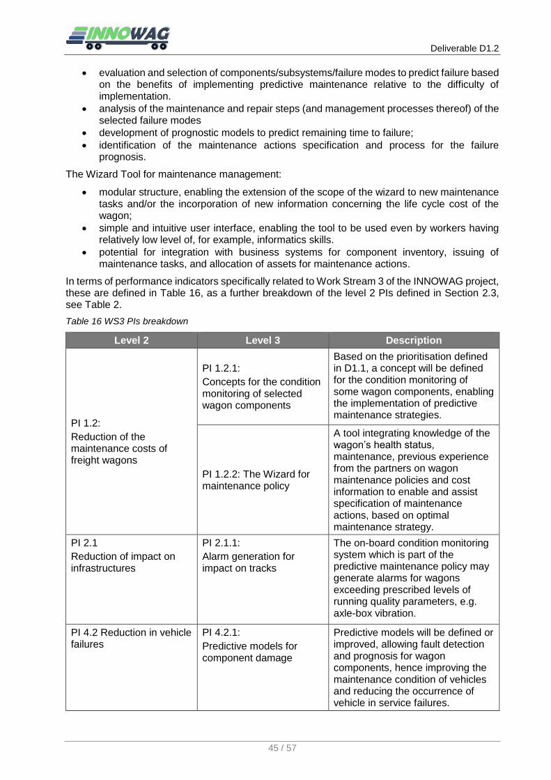
Deliverable D1.2
45 / 57
evaluation and selection of components/subsystems/failure modes to predict failure based on the benefits of implementing predictive maintenance relative to the difficulty of implementation.
analysis of the maintenance and repair steps (and management processes thereof) of the selected failure modes
development of prognostic models to predict remaining time to failure;
identification of the maintenance actions specification and process for the failure prognosis.
The Wizard Tool for maintenance management:
modular structure, enabling the extension of the scope of the wizard to new maintenance tasks and/or the incorporation of new information concerning the life cycle cost of the wagon;
simple and intuitive user interface, enabling the tool to be used even by workers having relatively low level of, for example, informatics skills.
potential for integration with business systems for component inventory, issuing of maintenance tasks, and allocation of assets for maintenance actions.
In terms of performance indicators specifically related to Work Stream 3 of the INNOWAG project, these are defined in Table 16, as a further breakdown of the level 2 PIs defined in Section 2.3, see Table 2.
Table 16 WS3 PIs breakdown
Level 2 Level 3 Description
PI 1.2:
Reduction of the maintenance costs of freight wagons
PI 1.2.1:
Concepts for the condition monitoring of selected wagon components
Based on the prioritisation defined in D1.1, a concept will be defined for the condition monitoring of some wagon components, enabling the implementation of predictive maintenance strategies.
PI 1.2.2: The Wizard for maintenance policy
A tool integrating knowledge of the wagon’s health status, maintenance, previous experience from the partners on wagon maintenance policies and cost information to enable and assist specification of maintenance actions, based on optimal maintenance strategy.
PI 2.1
Reduction of impact on infrastructures
PI 2.1.1:
Alarm generation for impact on tracks
The on-board condition monitoring system which is part of the predictive maintenance policy may generate alarms for wagons exceeding prescribed levels of running quality parameters, e.g. axle-box vibration.
PI 4.2 Reduction in vehicle failures
PI 4.2.1:
Predictive models for component damage
Predictive models will be defined or improved, allowing fault detection and prognosis for wagon components, hence improving the maintenance condition of vehicles and reducing the occurrence of vehicle in service failures.

Deliverable D1.2
46 / 57
PI 6.2:
Increase of digital information on wagon conditions
PI 6.2.1:
Monitoring of wagon condition
On-board sensors and data processing equipment allows the continuous monitoring of wagon condition
5.2 Sensing, data acquisition and data management
Sensors, and data acquisition/data management units represent the key hardware elements of predictive maintenance. Indeed, the health monitoring procedures described in D1.1 rely on the measurement of signals containing information concerning the state and condition of the system being monitored. The measured quantities relevant to the scope of the INNOWAG project are mostly acceleration and temperature signals that can be performed on different subsystems of the freight wagon, e.g. brakes, wheels, axles and bearings.
5.2.1 Functional and non-functional requirements
The data acquisition and data management system shall perform the following tasks:
perform regular measurement of parameters relevant to the condition of the system while the wagon is in service;
obtain, wherever possible, an estimate of the vehicle speed;
perform a processing of the measured signals to extract information concerning the condition of selected sub-systems in the wagon (wheels, axles, etc.). The processing of the measured signals can be performed either locally on the wagon or after the measured signals are transferred to a Predictive Maintenance server;
establish proper data communication with the Predictive Maintenance server so that the Wizard Tool can be updated with new available information concerning the condition of the wagon, both from on-board condition monitoring and inspection and maintenance processes. The procedure implementing data communication may involve human operation, e.g. reading of data by means of laptops or other portable computing/data storage units, transfer of data using SD cards or other physical supports.;
Additionally, the data acquisition and data management system shall satisfy the following non-functional requirements:
Data acquired on different wagons should be easily accessible to both vehicle operators and infrastructure managers, to allow for the definition of a comprehensive predictive maintenance policy which takes into account not only the components and the vehicle but the infrastructure as well;
the data management system shall be adaptable to facilitate the transfer of the maintenance management solutions adopted to different types of data and/or vehicle and technologies.
It should be finally noted that the Predictive Maintenance approach developed in the INNOWAG project is not meant to increase the level of safety in the operation of freight wagons, rather it is intended to reduce the total life cycle costs, and to increase the wagon’s availability and reliability, whilst maintaining the wagon within safe operating limits.
5.2.2 Technical specifications
The technical specifications for sensors to be used in WS3 are highly dependant on the specific component subsystem being addressed. Nevertheless, it is possible to anticipate in broad terms some of the most relevant specifications as follows
For acceleration sensors:
type: mono-axial/bi-axial/dual (acceleration + temperature transducers);

Deliverable D1.2
47 / 57
technology: Piezoelectric (PE)/Integrated electronic piezoelectric (IEPE), Piezoresistive (PR), Variable capacitance (VC);
Range: up to ± 200 g for sensors mounted on the axle/axlebox, up to ± 50 g for accelerometers mounted on the bogie frame;
Pass-band: 0.2-1000 Hz for measurements related to the health monitoring of wheels, axles, suspension components, 1-15000 Hz for measurements related to the condition monitoring of roller bearings;
For temperature sensors:
Range: –50 to 120° C
For both acceleration and temperature sensors:
Rugged design;
Hermetic sealing Resistance to dust, water and other contaminants: IP67 at least;
Corrosion resistant;
Ground isolated;
Low power consumption;
Manufactured in an approved ISO 9001 facility
For the hardware performing data acquisition, data processing and data storage, the technical specifications in terms of computing power, data storage capability etc. will be available in a more advanced stage of development of the health monitoring applications being addressed in WS3. At this stage, it is therefore possible to define the following specifications related to the resistance to environmental conditions:
Range of temperatures: -30 °C to 60 °C (operation) -40 °C to 85 °C (storage);
Shock resistant up to 30 g.
All the onboard electronics devices are subject to normative requirements presented in Section 3.3, and should have protection measures against environmental impacts descripted in Section 3.4.2.1.
5.3 Maintenance management
Implementation of a predictive maintenance strategy requires a thorough understanding and management of not only the diagnostic and prognostic stage, but also the specification, definition, and implementation of the required maintenance actions to maintain the vehicle in a safe operating condition. These maintenance action decisions have implications for the Life Cycle Cost (LCC), therefore a Wizard Tool will be created which incorporates cost data allowing the cost implications of different predictive maintenance policies to be identified and the optimum policy with respect to minimum LCC cost found.
5.3.1 Functional and non-functional requirements
The Wizard Tool realising the maintenance management process shall satisfy the following requirements:
Predictive failure models developed for selected components will be integrated with improved maintenance rules, limits and procedures, to feed into an integrated predictive maintenance system;
The wizard tool shall establish proper data communication with the hardware installed on board the wagons, to enable the transfer of data. This may involve human operation in different ways, as already described in Section 5.2.1;
The software shall be capable to integrate different information sources, particularly information related to the condition of the wagon and the available information concerning the cost of the maintenance action at stake;
Deliverable D1.2
48 / 57
The software shall incorporate statistical models using different data types (age, condition monitoring and inspection data);
The software shall include a Cost Breakdown Structure;
The software shall support a cost-effective maintenance decision;
The software’s interface shall be user-friendly, so that it can be used by relatively non-skilled workers.
5.3.2 Technical specifications
The condition-based maintenance module being developed in the INNOWAG project is basically an expertise and software application. Hence, technical specifications do not apply in strict sense. The Condition Based Maintenance strategy developed will consider MIMOSA standard (also ISO-13374), in order to create a result that can perfectly fit a standardised vision of Condition Based Maintenance, and not just a dedicated model.
The intended function of predictive maintenance management is to ensure the Reliability, Availability Maintainability and Safety (RAMS) of the freight vehicle in service. For Railway applications RAMS is defined in EN 50126, parts 1 and 3 being relevant to vehicle maintenance. One of the purposes of the standard is to define the process for analysing RAM, specifying the requirements for RAM within a system (that is, the vehicle in this context), and verification of RAM. In particular, EN 50126, Part 3 includes a section specifying RAM parameters to be incorporated into LCC Modelling and also a section on operation and maintenance of the system to ensure that the specified system RAM is maintained through the life cycle. Therefore, this standard will be considered in the development of the predictive maintenance strategies and the Wizard Tool, the extent to which it will be considered is that the term used in the definition of the maintenance strategy and Wizard Tool will be consistent and compatible with the terms defined in the standard, so that the strategy and tool can be correlated with the standard. Also, the definition of the maintenance processes will be defined such that the specified RAM of the system is maintained, and that where applicable, the Wizard Tool will be made compatible with the specification and verification of RAM as defined in part 3, particularly the parameters related to LCC.

Deliverable D1.2
49 / 57
6. CONCLUSIONS
The INNOWAG PIs have been defined to assess the future developments within each Work Stream. The PI breakdown was structured in three levels, from the strategy level to the more detailed WS-specific level representing the key outcomes of each WS. The first two levels were introduced in Section 2, while the third levels were specified in WS-related sections respectively. All the three levels are summarised in Table 17.
Table 17 Summary table of INNOWAG PIs
Level 1 Level 2 Level 3
PI 1:
LCC reduction of freight vehicles
PI 1.1:
Reduction in operational cost
PI 1.1.1
Increased energy efficiency
PI 1.2:
Reduction of the maintenance costs of freight vehicles
PI 1.2.1:
Concepts for the condition monitoring of selected wagon components
PI 1.2.2: The Wizard for maintenance policy
PI 1.3:
Reduction of the manufacturing costs of freight vehicles
PI 1.3.1
Material savings
PI 1.3.2
Reduction of manufacturing processes costs
PI 2:
Reduction of infrastructure LCC
PI 2.1:
Reduction of impacts on infrastructures
PI 2.1.1:
Alarm generation for impact on tracks
PI 2.1.2
Reduction of maintenance activities
PI 3:
Increase in freight train capacity
PI 3.1:
Increase of the payload-tare weight ratio
PI 3.1.1
Reduced tare weight
PI 3.1.2
Increased payload
PI 4:
Increase in reliability
PI 4.1:
Reduction in cargo damage
PI 4.1.1:
Alarm generation
PI 4.2:
Reduction in vehicle failures
PI 4.2.1:
Predictive models for component damage
PI 5:
Improvement of interoperability
PI 5.1
Data interchange between different applications and operators
PI 5.1.1:
Easy access to the information by different interested users by means of data management solutions
PI 5.1.2:
Data communication with other telematics applications
PI 5.2
Technology transfer for the development of vehicle condition monitoring system
PI 5.2.1:
Adaption of energy harvesting powering systems
PI 5.2.2:
Adaption of wireless networking of sensors

Deliverable D1.2
50 / 57
PI 6:
Digitalisation
PI 6.1:
Increase of digital information on cargo conditions
PI 6.1.1:
Report frequency
PI 6.2:
Increase of digital information on wagon conditions
PI 6.2.1:
Continuous monitoring of wagon condition
PI 7:
Attractiveness of rail freight transport
PI 7.1:
Increase of the visibility of shipment status
PI 7.1.1:
Type of status information
PI 7.2
Overcoming the obstacles for telematics application on freight wagons
PI 7.2.1:
Resolving the issue of power supply
PI 7.2.2:
Resolving the issue of wiring
PI 8:
Environmental friendly
PI 8.1:
Noise abatement PI 8.1.1
Reduced noise emission
WS1: Cargo Condition Monitoring
With regard to cargo condition monitoring, a series of relevant regulations and standards were presented, with which the train-side monitoring systems should comply (applicable to both cargo and vehicle condition monitoring systems). Considering the development objectives, container wagons carrying LDHV goods and tank wagons carrying flammable gas are defined as the application cases. These two cases were subsequently analysed in order to extract requirements from the point of view of the interested stakeholders and the operational environment of the CCMS. As the developments within WS1 aim at reaching TRL 5, namely validating the envisaged technologies in an appropriate railway environment, the developed CCMS cannot fulfil all requirements, and cover all the application scenarios possibly involved. The business model and some issues raised by safety-related monitoring of dangerous goods are out of the project scope as well.
Taking into consideration the restrictions and based on the application cases, the requirements and general specifications of a technical nature were investigated for the individual functional modules of the CCMS respectively. The more detailed technical specifications will be available for the INNOWAG demonstrator in a more advanced design stage. The summary of the prioritised requirements in Table 12 enables the following conclusions.
System level:
The CCMS consists of the onboard units and IT infrastructure. The envisaged technologies belong to the onboard units, while IT infrastructure is to be established based on the existing platform and/or software.
The development of the onboard units is subject to the applicable standards and the realistic operating conditions.
Bearing in mind that the available power provided by energy harvesters is limited, advanced technologies in some areas, therefore, might not be employed. The selection of the sensors and the design of the wireless sensor network has to consider this as well.
Data acquisition:
Temperature measurements as well as tracking and tracing of loading units must be successfully implemented in both application cases.

Deliverable D1.2
51 / 57
Other proposed measurements will be implemented or planned according to the available resources.
RFID sensors might be employed for conducting measurements.
In this regard, the sensor network will be designed to be scalable by adding or removing sensor nodes, each of which can interface different sensor types.
Identification of cargos will not require any additional hardware.
Power supply:
The energy demanded by the onboard units will be provided by energy harvesters, along with power storage equipment and power management modules.
Solar, RF and vibration energy harvesters are considered most feasible solutions in the context of rail freight transport to power the individual sensor nodes and other electronic devices for meeting the necessary operating conditions.
Data communication:
The best WSN architecture has not been identified. Nevertheless, it must represent a good trade-off between power consumption and data delivery performance.
RFID communication might be integrated in the WSN.
The data will be transmitted from the train to the ground either via mobile network or through interaction between train-side RF tags and wayside RF-readers. The selection relies especially on the available energy and the amount of data.
Data processing, storage and representation
The onboard units will permit data logging and allow basic data processing, including the trigger of alarms/warnings.
The platform or/and software for establishing IT Infrastructure will be selected in the future work.
WS2: Wagon Design
The wagon design work stream within INNOWAG will mainly focus on developing a design concept with reduced mass compared to current designs of freight vehicles (lightweighting). However, where appropriate, consideration will also be given to improving the characteristics of the wagon concept design in other critical areas of wagon performance, such as reduction of impacts on the track, improved aerodynamics, noise reduction, etc., which may be also addressed by the novel design.
The wagon lightweighting will be addressed through:
Materials (selection, new manufacturing techniques, new joining processes, etc.)
‘Smart’ optimised design (using novel profiles, optimised shapes, etc.)
The potential mass reduction is foreseen in key parts of a freight vehicle, i.e.:
Running gear (the mass reduction is still limited due to stability and running behaviour issues)
Structural frames (good potential for reduction, up to 25-30%; ~20% was achieved for flat a wagon in SUSTRAIL)
Wagon body (very good potential, foreseen up to 40-50%)
However, the potential to reduce the mass of auxiliary equipment and components (e.g., draw gear, braking system, coupling system, etc.) is still limited by both technical and regulatory

Deliverable D1.2
52 / 57
barriers. Therefore, INNOWAG will not aim to reduce the mass of components in these categories.
In order to address the relevant wagon parts (as explained above), and considering the market drivers and trends as well, three different types of wagons have been selected for further work. These have been selected based on the expected future freight demands and the potential opportunities within the design of the wagon types for lightweighting; INNOWAG wagon design will therefore focus on the following selected wagon types:
Flat wagon type, enabling the container and other goods transport
Open self-discharge wagon for bulk materials (open ‘hopper’ type)
Cereals wagon (covered ‘hopper’ type)
Standardisation and compliance with regulatory framework:
The INNOWAG wagon design concept will comply with the existing standards and regulation (EN, ISO, UIC leaflets, TSI, etc.). However, it is anticipated that there might be situations encountered where the existing regulation is not appropriate (e.g., where the standard defines the requirements for metallic structures and the design concept uses composite materials for critical parts and components, making the specification in the standard inappropriate). If it transpires that the application of the existing standard is not appropriate, then the gaps will be identified and recommendations made regarding the needs for standards modification.
Since the focus of the development work for the INNOWAG concept design is on lightweighting of the structures, it will mainly use standard auxiliary equipment and components. However, considering ongoing work in other S2R projects, alternative innovative solutions and emerging technologies may be considered for inclusion and integration into the concept design as well; these might include novel designs of suspension system, disk brakes, automatic coupler, and other equipment and components.
WS3: Predictive Maintenance
For the predictive maintenance work stream of the project, a set of specific performance indicators was defined. Additionally, functional and non-functional requirements were defined for the different units in the work stream, i.e.:
Sensing, data acquisition and data management;
Maintenance management
These requirements include the specification of the process for developing a predictive maintenance strategy for selected components of freight vehicles as a demonstrator case study for the application of predictive maintenance procedures to this segment of the railway industry. This included the specification of the process from:
analysis of components and failure modes,
through
the identification of measurable parameters capable of identifying developing faults,
the identification of sensor techniques and technologies to measure those parameters,
the development of prognostic models,
the analysis and identification of maintenance actions and management processes necessary to maintain wagons in a safe operable condition, and

Deliverable D1.2
53 / 57
the development of a model of Life Cycle Cost data related to wagon operation and maintenance using predictive maintenance practices,
to
the development of a Wizard Tool to assist in the optimisation of predictive maintenance policies to maintain the wagon within the required limits whilst minimising Life Cycle Costs.
For all hardware components, technical specifications were defined.
The normative framework was also examined, identifying the standards that are relevant to work to be carried out in WS3.
Deliverable D1.2
54 / 57
References
Arcadius, T. C., Gao, B., Tian, G., & Yan, Y. (2017). Structural Health Monitoring Framework Based on Internet of Things: A Survey. IEEE Internet of Things Journal.
COSMOS project (2013), Efficient intermodal wagons, the EU project under the framework of Marco Polo Common Learning Action Cooperative Solutions for Managing Optimized Services, source: http://www.intermodal-cosmos.eu/content/e4/e251/e259/e270/COSMOS_WP1_Good-Practice-Manual_12_Efficient-Intermodal-Wagons_KC-HC_20130430_eng.pdf
European Rail Research Institute (ERRI) (1997), B12 / RP17 report: Programme of tests to be carried out on wagons with steel underframe and body structure (suitable for being fitted with the automatic buffing and draw coupler) and on their cast steel frame bogies, 8th edition
European Standard (1999), EN 50126-1:1999 Railway applications — The specification and demonstration of Reliability, Availability, Maintainability and Safety (RAMS) — Part 1: Basic requirements and generic process
European Standard (2008), EN 50126-3:2008 Railway applications — The specification and demonstration of Reliability, Availability, Maintainability and Safety (RAMS) — Part 3: Guide to the application of EN 50126-1 for rolling stock RAM
European Standard (2009), EN 15551:2009 + A1:2010: Railway applications. Railway rolling stock. Buffers
European Standard (2009), EN 15566:2009 + A1:2010: Railway applications. Railway rolling stock. Draw gear and screw coupling
European Standard (2010), EN 12663-2:2010 Railway applications. Structural requirements of railway vehicle bodies Part 2: Freight wagons. European Committee for Standardisation (CEN)
European Standard (2010), EN 14067-6 Railway applications. Aerodynamics. Requirements and test procedures for cross wind assessment
European Standard (2011), EN 13749:2011: Railway applications. Wheelsets and bogies – Method of specifying the structural requirements of bogie frames. European Committee for Standardisation (CEN)
European Standard (2011), EN 15807:2011: Railway applications. Railway rolling stock. Pneumatic half couplings
European Standard (2011), EN 15827:2011: Railway applications. Requirements for bogies and running gears. European Committee for Standardisation (CEN)
European Standard (2013), Draft EN 16019:2013 (DPC: 13 / 30279823 DC): Railway applications. Automatic coupler – Performance requirements, specific interface geometry and test method
European Standard (2014), EN 50125-1:2014, Railway applications - Environmental conditions for equipment – Part 1: Rolling stock and on-board equipment, German version EN 50125-1:2014
Hecht, M. et al. (2017), Strategien zur effektiven Minderung des Schienengüterverkehrslärms, Umweltbundesamt
IMPACT-1 (2017), Indicator Monitoring for a new railway PAradigm in seamlessly integrated Cross modal Transport chains – Phase 1, EU project under Shift2Rail initiative, source accessed: http://cordis.europa.eu/project/rcn/205644_en.html , 21.04.2017
Melexis (2017), Evaluation Board for MLX90129, Product of Melexis Inspired Engineering, Source: https://www.melexis.com/en/product/EVB90129/Evaluation-Board-MLX90129 , accessed 05.05.2017
Microsens (2017), MSGS gas sensor, source: http://microsens.ch/products/MSGS.htm

Deliverable D1.2
55 / 57
NOI TSI (2014), COMMISSION REGULATION (EU) No 1304/2014 of 26 November 2014 on the technical specification for interoperability relating to the subsystem ‘rolling stock — noise’ amending Decision 2008/232/EC and repealing Decision 2011/229/EU
Qian, J. et al. (2011), A Passive UHF Tag for RFID-based Train Axle Temperature Measurement System, IEEE Custom Integrated Circuits Conference (CICC), 2011
RailBusiness (2017), Kombi-Verkehr legt überproportional zu, ISSN 1867-2728. 24. April 2017
Rakshit, S.M. et al. (2012), Challenges in Current Wireless Sensor Technology for Railcar Status Monitoring for North America’s Freight Railroad Industry, the ASME/ASCE/IEEE 2012 Joint Rail Conference, 2012
RFID Sensor Systems (2017), RFID Sensor Systems Gen2 ID-only Tag Product Matrix, Source: http://www.rfidsensorsystems.com/products/PassiveTags.htm , accessed 05.05.2017
Roll2Rail (2016), Evaluation Methodology Description, the lighthouse project of Shift2Rail within the Horizon 2020 program: New Dependable Rolling Stock for a More Sustainable, Intelligent and Comfortable Rail Transport in Europe, Deliverable 9.1
S2R JU (2016), Annual Work Plan 2017 & Budget Figures, 23.12.2016
Shoeib, R., Hecht, M. (2013), Energy saving by aerodynamics optimisation of hopper wagons, Rail-Aerodynamics 2013, 2nd International Symposium Rail-Aerodynamics: Aerodynamics of Trains and Infrastructure, Berlin, 15.-17. Mai 2013, Bahntechnik Aktuell, Band 44/2013, S. 95-111
SPECTRUM project (2012), Logistics and market analysis. FP7-SST.2010.5.2-3.: Grant agreement number: 266192. Deliverable D1.3
Sunny, A. I., Tian, G. Y., Zhang, J., & Pal, M. (2016). Low frequency (LF) RFID sensors and selective transient feature extraction for corrosion characterisation. Sensors and Actuators A: Physical, 241, 34-43.
SUSTRAIL project (2012), Deliverable D2.4: Future vehicle performance requirements, FP7 project “The sustainable freight railway: Designing the freight vehicle – track system for higher delivered tonnage with improved availability at reduced cost”
TAF TSI (2014), COMMISSION REGULATION (EU) No 1305/2014 of 11 December 2014 on the technical specification for interoperability relating to the telematics applications for freight subsystem of the rail system in the European Union and repealing the Regulation (EC) No 62/2006
TIS (2014), Requirements for Telematics and Sensor Technology, white paper
TIS (2017), ITSS-Interface2-Ready Specification, source: http://www.innovative-freight-wagon.de/wp-content/uploads/ITSS_Interface_2_Ready_Specification.pdf
UIC (2016), Railway Noise in Europe, State of the art report, UIC, March 2016
UIC 505-1 leaflet (2006), Railway transport stock - Rolling stock construction gauge, Ed. no. 10
UIC 510-1 leaflet (1978), Wagons - Running gear – Normalisation, Ed. no. 9
UIC 517 leaflet (2007), Wagons - Suspension gear – Standardisation, Ed. No. 7
UIC 520 leaflet (2003), Wagons, coaches and vans - Draw gear – Standardisation, Ed. No. 7
UIC 526-1 leaflet (2008), Wagons - Buffers with a stroke of 105 mm, Ed. No. 3
UIC 527-1 leaflet (2005), Coaches, vans and wagons - Dimensions of buffer heads - Track layout on S-curves, Ed. No. 3
UIC 530-1 leaflet (1982), Constructional conditions for wagons to be observed with a view to fitting the automatic coupler of the Member Railways of the UIC and OSJD respectively, Ed. no. 2

Deliverable D1.2
56 / 57
UIC 532 leaflet (1979), Trailing stock - Signal lamp brackets - Coaches - Fixed electric signal lamps, Ed. no. 9
UIC 535-2 leaflet (2006), Standardisation and positioning on wagons of steps, end platforms, gangways, handrails, tow hooks, automatic coupler (AC), automatic draw-on coupling and brake valve controls on the UIC member RUs and OSJD member Rus, Ed. no. 4
UIC 536 leaflet (1967), Towing hooks for wagons, Ed. no. 3
UIC 543 leaflet (2014), Brakes - Regulations governing the equipment of trailing stock, Ed. no. 14
UIC 544-1 leaflet (2014), Brakes - Braking performance, Ed. no. 6
UIC 571-2 leaflet (2001), Standard wagons - Ordinary bogie wagons - Characteristics, Ed. no. 6
UIC 571-3 leaflet (2004), Standard wagons - Special-purpose wagons - Characteristics, Ed. no. 6
UIC 571-4 leaflet (2014), Standard wagons - Wagons for combined transport – Characteristics, Ed. no. 6
UIC 575 leaflet (1995), Wagons - Label holders (Interchangeability) and hazard identification panels, Ed. no. 4
UIC 577 leaflet (2012), Wagon stresses, Ed. no. 5
UIC 581 leaflet (1983), Wagons - Lifting – Rerailing, Ed. no. 1
UIC 812-1 leaflet (1989), Technical specification for the supply of rolled or forged wheel centres for tyred wheels for trailing stock. Quality requirements, Ed. no. 4
UIC 812-2 leaflet (2002), Solid wheels for tractive and trailing stock - Tolerances, Ed. no. 2
UIC 812-3 leaflet (1984), Technical specification for the supply of solid (monobloc) wheels in rolled non-alloy steel for tractive and trailing stock, Ed. no. 5
UIC 812-4 leaflet (1990), Technical specification for the supply of tyred wheels for tractive and trailing stock. Type fitting and tolerances, Ed. no. 1
UIC 812-5 leaflet (1988), Technical specification for the supply of rolled or forged steel wheel centres for tractive and trailing stock - tolerances and surface roughness, Ed. no. 1
UIC 813 leaflet (2003), Technical specification for the supply of wheelsets for tractive and trailing stock - Tolerances and assembly, Ed. no. 2
UIC 814 leaflet (1988), Technical specification for the official testing and supply of greases intended for the lubrication of railway vehicle roller bearing axle boxes, Ed. no. 2
UIC 822 leaflet (2003), Technical specification for the supply of helical compression springs, hot or cold coiled for tractive and trailing stock, Ed. no. 5
UIC 825 leaflet (1985), Technical specification for the supply of draw hooks with nominal load equal to 250 kN, 600 kN or 1000 kN for tractive and trailing stock, Ed. no. 4
UIC 826 leaflet (2004), Technical provisions for the supply of screw couplings for tractive and trailing stock, Ed. no. 3
UIC 827-1 leaflet (1990), Technical specification for the supply of elastomer components for buffers, Ed. no. 2
UIC 828 leaflet (1960), Technical specification for the supply of welded components for buffers, Ed. no. 1
UIC 842-1 leaflet (1975), Technical specification for the supply of paint products for the protection of railway vehicles and containers, Ed. no. 1
UIC 842-2 leaflet (1975), Technical specification for methods for testing paint products, Ed. no. 3
Deliverable D1.2
57 / 57
UIC 842-3 leaflet (1979), Technical specification for the surface preparation of metallic and non-metallic materials used in the construction of railway vehicles and containers, Ed. no. 2
UIC 842-4 leaflet (1979), Technical specification for the protection against corrosion and painting of wagons and containers, Ed. no. 2
UIC 842-6 leaflet (1979), Technical specification for the quality inspection of railway vehicle paint systems, Ed. no. 2
ViWaS project (2015), Prototype intelligent telematics devices, EU project under FP7 framework: Viable Wagonload Production Schemes, Deliverable D7.3, 02.2015
Zhang, H., Yang, R., He, Y., Tian, G. Y., Xu, L., & Wu, R. (2016), Identification and characterisation of steel corrosion using passive high frequency RFID sensors. Measurement, 92, 421-427.
Zhang, J., & Tian, G. Y. (2016), UHF RFID Tag Antenna-Based Sensing for Corrosion Detection & Characterization Using Principal Component Analysis. IEEE Transactions on Antennas and Propagation, 64(10), 4405-4414.
Zhang, J., Tian, G. Y., & Zhao, A. B. (2017), Passive RFID sensor systems for crack detection & characterization. NDT & E International, 86, 89-99.
Zhang, J., Tian, G. Y., Marindra, A. M., Sunny, A. I., & Zhao, A. B. (2017), A review of passive RFID tag antenna-based sensors and systems for structural health monitoring applications. Sensors, 17(2), 265.