innovative options for flexible pipeline & caisson … duthie...x lay and install 12” flexible...
TRANSCRIPT

MCE Deepwater Development 2016
PAU, FRANCE • 5-‐7 APRIL 2016
Innovative Options for Flexible Pipeline & Caisson Repair
Stewart DuthieFlexlife Ltd.

MCE Deepwater Development 2016
Agenda• Armadillo® Technology
Overview• Case study 1
• Flowline anchor damage
• Case study 2• Blocked riser vent
ports• Caisson repair solutions• Case study 3
• Riser repair in I-tube• Case study 4
• Low pressure pipeline Leak sealing
• Current developments• Cross-linking polymer
repair solutions• Q&A
MCE Deepwater Development 2016
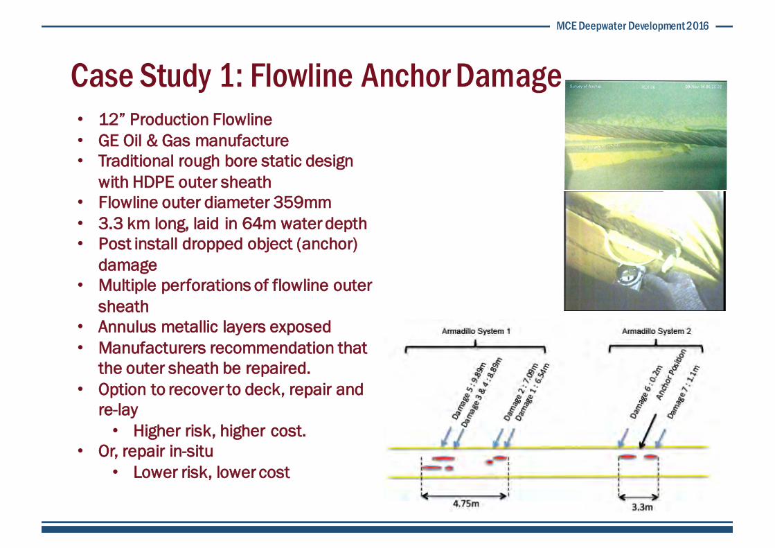
Case Study 1: Flowline Anchor Damage• 12” Production Flowline• GE Oil & Gas manufacture• Traditional rough bore static design
with HDPE outer sheath• Flowline outer diameter 359mm• 3.3 km long, laid in 64m water depth• Post install dropped object (anchor)
damage• Multiple perforations of flowline outer
sheath• Annulus metallic layers exposed• Manufacturers recommendation that
the outer sheath be repaired.• Option to recover to deck, repair and
re-lay• Higher risk, higher cost.
• Or, repair in-situ • Lower risk, lower cost
INTEGRATED TRANSPORTATION AND INSTALLATION OF OFFSHORE FACILITIES
FOR YEAR 2014-2016
Document No. 02D-50 30-00-TI-
PRO-0002
12” CDW-C Production Flowline No. 2, Length No. 2 Repair Procedure
Revision : G1
Page 5 of 35
Location: Cendor FPSO (CDP-A)
x Lay and install 12” Flexible Riser (Production #2)
1.3. Procedure Overview/Document Scope of Work
The purpose of this document is to provide clear step-by-step procedure to complete the repair of 12” CDW-C Production Flowline No. 2, Length No. 2 utilizing DP MSV Kreuz Installer. Location of the damages are shown in the Diagram 1 below and detail location of the damage location can be referred to the Appendix C.
All detailed methodology and sketches are included in this procedure to provide clear and discrete packages and scope of work for the offshore construction team.
Diagram 1: Schematic diagram of the damage location on 12” CDW-C Flexible Flowline (Prod #2)

MCE Deepwater Development 2016
Case Study 1: Flowline Anchor Damage• Modular design of Armadillo®
facilitates the repair to long areas of outer sheath damage
• Flowline lifted using subsea A-frame• Diver installed, segment by segment
over damage location• Post-install, flowline has one end
lowered to seabed• FlexGel-A™ is then filled from highest
point• Controlled from topsides by Flexlife
engineers• FlexGel-A™ is lighter than seawater• Displaces seawater within the
Armadillo annulus• Re seals the flowline outer sheath
The flowline was lifted horizontally using air bags so that it was at a suitable height for the divers to be able to attach the Armadillo segments [Ref 8]. The Armadillo segments were then lowered down to the divers on the seabed inside a diver cage (See Figure 6.3 below). Once assembled, 1m long vent hoses were attached to the three vent ports (gel outlet / seawater vent). The gel inlet hose was not connected until the gel receptacle was on the seabed.
Figure 6.3: Armadillo Segments In Diver Cage
6.5. Installation Methodology
The gel fill of the Armadillo assemblies was carried out as shown in Figure 6.4. This method allowed the gel receptacle to be sited close to the flowline, reducing the distance that the gel was required to be pumped.
Figure 6.4: Armadillo Gel Fill Methodology
Petrofac Cendor Armadillo Installation Summary Report
Doc. No: FLX-PEM-005-000-REP-26685-r2 Page 8 of 14

MCE Deepwater Development 2016
Case Study 1: Flowline Anchor Damage• Lessons learned• Prudent to carry additional
segments.• Original damage length was
indicated to span 8.25m• On installation, spare segments
were used to cover 10.3m• Once FlexGel-A™ is activated,
vessel SIMOPS should be avoided
MCE Deepwater Development 2016
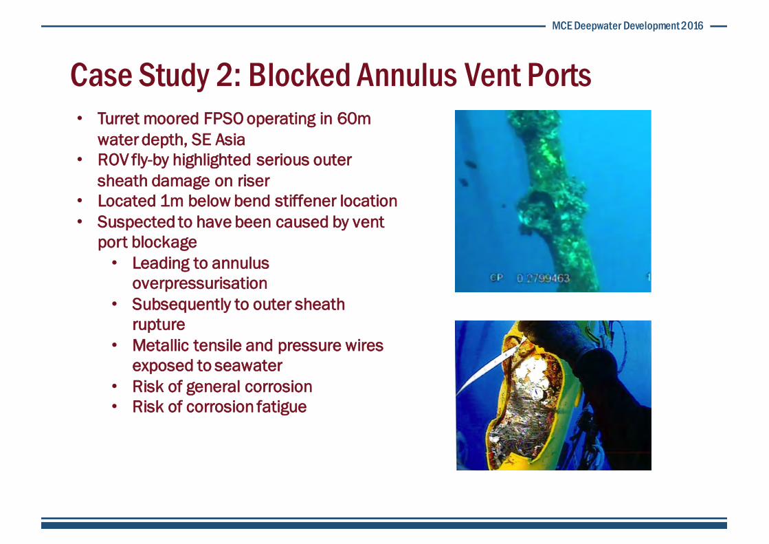
Case Study 2: Blocked Annulus Vent Ports• Turret moored FPSO operating in 60m
water depth, SE Asia• ROV fly-by highlighted serious outer
sheath damage on riser• Located 1m below bend stiffener location• Suspected to have been caused by vent
port blockage• Leading to annulus
overpressurisation• Subsequently to outer sheath
rupture• Metallic tensile and pressure wires
exposed to seawater• Risk of general corrosion• Risk of corrosion fatigue

MCE Deepwater Development 2016
Case Study 2: Blocked Annulus Vent Ports• Detailed inspection data• Decision to use ROV deployed ultrasonic inspection• Patented FlexScan™ technology• Using Neptune UT scanner• UT offers clear information regarding transitions between and through materials• The speed of sound through a known material enables accurate thickness
measurement• Used to reduce conservatism in life extension study
• Global dynamic analysis• Local fatigue analysis

MCE Deepwater Development 2016
Case Study 2: Blocked Annulus Vent Ports• Armadillo® is designed to accommodate
small discrepancies in riser o/d• Constructed from polymer, typically HDPU• Failure root cause, in this instance, was
sheath over-pressurisation caused by marine growth induced vent port blockage
• Post install on the riser, additional venting system was installed through Armadillo®
repair clamp• Armadillo® annulus was then injected with
FlexGel-A™ to provide an isolation between the seawater and the riser annulus
• Riser End-Fitting Pressure Relief Valves were also replaced
• This exercise allowed residual pressure to be released on two adjacent risers, BEFORE the outer sheaths ruptured

MCE Deepwater Development 2016
Case Study 2: Blocked Annulus Vent Ports• Lessons learned• Tolerance fit is essential to repair a
deformed outer sheath• Ovality was in excess of 20%
• Metrology is especially complex where a riser has been subject to overpressurisation• Once damaged sheath had been
stripped back, damage length was 50% greater than anticipated
• The build up of marine growth requires careful maintenance, particularly on risers with subsea end-fittings.
• Routine removal of marine growth, particularly around Pressure Relief Valves (PRV) is essential.

MCE Deepwater Development 2016
Case Study 3: Flexible Riser Repair in I-Tube • Riser positive pressure annulus testing
indicates a loss of outer sheath integrity at 13m below MSL
• Confirmed by CVI• Inaccessible location • No apparent marketplace solution• FlexGel® developed to address
corrosion concerns• Tuned SG• Tuned viscosity• Immiscible• Thixotropic• Non flammable• Replaces seawater with benign
gel• Environmentally approved by
CEFAS, OCNS• Mitigates splash zone corrosion
MCE Deepwater Development 2016
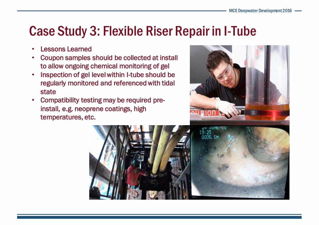
Case Study 3: Flexible Riser Repair in I-Tube • Lessons Learned• Coupon samples should be collected at install
to allow ongoing chemical monitoring of gel• Inspection of gel level within I-tube should be
regularly monitored and referenced with tidal state
• Compatibility testing may be required pre-install, e.g. neoprene coatings, high temperatures, etc.

MCE Deepwater Development 2016
Case Study 4: J-Tube Polymer Leak Prevention • UIC occurs in stuffing gland between in
gas tight floor of CONDEEP platform leg• Leads to leak in rundownline• Inaccessible location• Production shut-in from platform and
linked fields• No apparent marketplace solution• FlexGel-PS™ developed to seal leak
• Tuned SG• Injected as liquid• Tuned cure time • Replaces bore fluid becoming an
elastic solid• Seals leak location internally• Enabling permanent external repair
to be facilitated• Can be chemically ‘broken’ into
component liquids

MCE Deepwater Development 2016
Case Study 4: J-Tube Polymer Leak Prevention • Lessons Learned• Coupon samples should be collected at
install to allow chemical monitoring of polymer plug
• Chemical breaking of FlexGel-PS™
requires an oxidising agent• Volume injected should be engineered to
the minimum required to achieve objective in order to simplify the, post repair, removal process

MCE Deepwater Development 2016
Current Developments • During operational life, leaking J-tube
seals can lead to issues with corrosion within caissons, I-tubes, J-tubes
• Dosing regime compromised by seawater leaching/dilution
• If unchecked can, and has, resulted in riser failures
• Current developments• Adapt FlexGel-PS™ by tuning SG heavier
than seawater• Inject through J-tube to form a
heavier than seawater elastic plug• Reinstate J-tube seal• Reinstate design dosing regime• Adapt inspection frequency and
continue to operate

MCE Deepwater Development 2016
Q&A
• Stewart Duthie• Manager, Subsea Technology• Flexlife Ltd.• [email protected]