innovative plastics weight-out+ performancecdn.thomasnet.com/ccp/01052374/189656.pdf · processing...
TRANSCRIPT

WEIGHT-OUT+PERFORMANCEDesign and Process Guide for Carbon Fiber Reinforced ULTEM™ (PEI) Compound
INNOVATIVE PLASTICS

2 INNOVATIVE PLASTICS2 INNOVATIVE PLASTICS
Innovative Plastics is a strategic business unit of SABIC. Founded in 1976, SABIC is today the first public, global multinational enterprise headquartered in the Middle East. Its products range from bulk commodity chemicals to highly engineered plastics for demanding applications.
It is a leading producer of polyethylene, polypropylene, glycols, methanol and fertilizers, and the fourth largest polyolefin producer.
SABIC’s businesses are grouped into Chemicals, Performance Chemicals, Polymers, Innovative Plastics, Fertilizers and Metals. It has significant research resources with dedicated Technology & Innovation Centers in Saudi Arabia, the Netherlands, Spain, the USA, India, China and Japan.
A SABIC COMPANY

INNOVATIVE PLASTICS 3
We believe that SABIC customers deserve the full benefit of every advantage our enterprise can offer. After all, our success is defined by our customers’ success. And with over 80 years of experience pioneering advanced engineering thermoplastics, SABIC’s Innovative Plastics business is positioned to help create new opportunities for growth and breakthrough applications.
We offer expertise and experience to our customers in a variety of ways:
• Material solutions to help drive innovation and market leadership
• Design, logistics and processing expertise to spark new ideas and better efficiencies
• Unwavering commitment to build long-term relationships with ingenuity, trust and continuous improvement.
It’s what we strive for and work to deliver… a mutual benefit
Excellence and nothing less.
INNOVATING FOR CUSTOMER SUCCESS
INNOVATIVE PLASTICS 3
CONTENTS
A SABIC COMPANY 2
EXPERIENCE THAT COUNTS 4
METAL CONVERSION 6
DESIGN FOR PLASTIC 8
CARBON FIBER REINFORCED ULTEM COMPOUND PROPERTIES
10
PLASTIC PART DESIGN 12
PROCESSING GUIDE 14
MOLD DESIGN 17
MACHINE SPECIFICATIONSCONSIDERATIONS
19
INJECTION MOLDIING PROCESSING
21
A GLOBAL PARTNER 22

4 INNOVATIVE PLASTICS
EXPERIENCE THAT COUNTS
SABIC’s Innovative Plastics business has been a key player in the aerospace industry from the beginning, pioneering new material technologies to make aircraft lighter, more efficient, enjoyable, comfortable and safer.
Today, SABIC continues to innovate by providing game-changing carbon fiber reinforced ULTEM PEI compound technologies that offer the advanced material solutions our customers demand.
We offer expertise and experience to help our customers:• Reduce aircraft weight for increased
fuel efficiency
• Achieve greater design flexibility
• Comply with FAA, Boeing and Airbus specifications
It’s all part of our commitment to serve the aircraft industry with product innovations and business support to achieve new heights in safety, efficiency and profitability.
Reducing the weight of interior aircraft components is paramount to the airline industry. For American Airlines,* each pound of weight removed from an aircraft will save as much as 11,500 gallons of fuel annually across a fleet of 600 aircraft.
4 INNOVATIVE PLASTICS
* http://www.aa.com/i18n/aboutUs/environmental/main.jsp

INNOVATIVE PLASTICS 5INNOVATIVE PLASTICS 5

6 INNOVATIVE PLASTICS
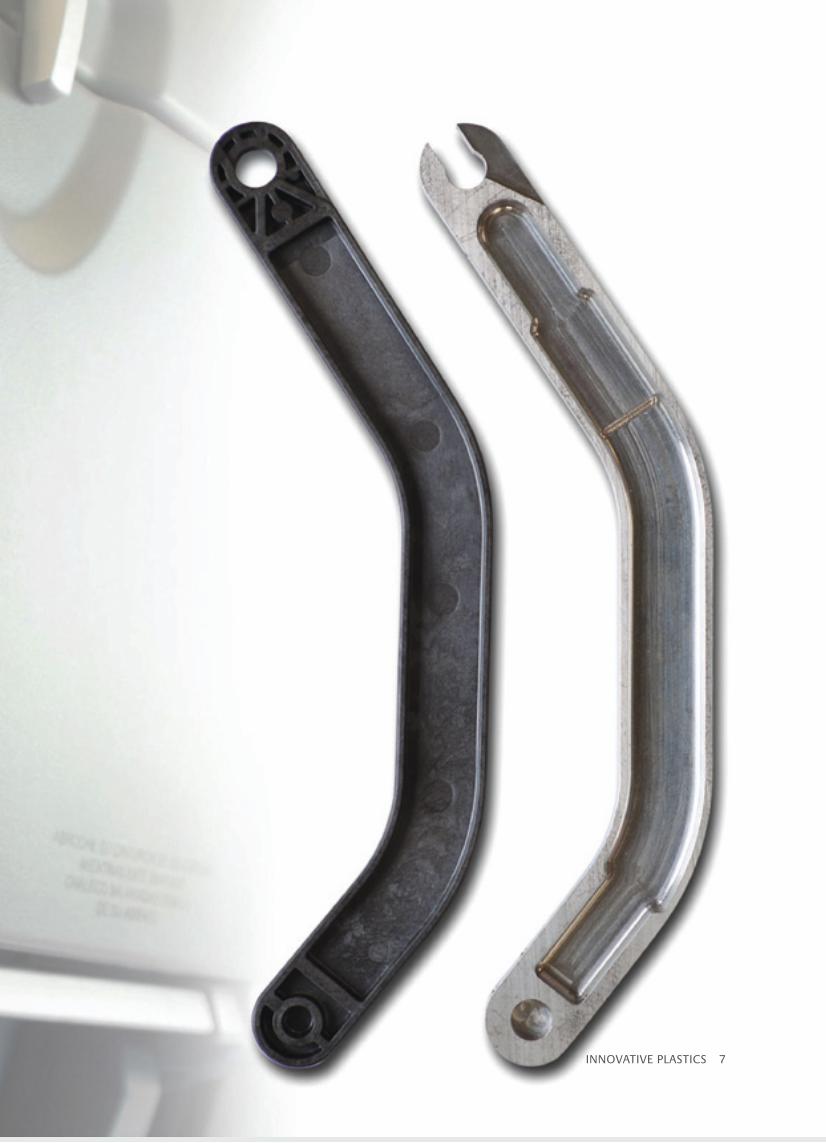
Plastic has inherent advantages over metal. When plastic is used, assemblies with high part counts can be consolidated into single components with complex geometry. Through part reduction, savings can be potentially realized throughout a product’s manufacturing life cycle, not only in the piece price. Typically engineering time, speed to market, assembly time, inventory costs and quality issues can all benefit from part reduction. When approaching a potential application, good opportunities
are commonly those which have high part counts, high use of fasteners or connectors, or high assembly time.
Injection molding is the most common application for part consolidation, however extrusion, thermoforming, composites and additive manufacturing are all processes that can be used to drive improvements within an aircraft. ULTEM resin is versatile enough to be used in any of these applications.
METAL CONVERSION
INJECTION MOLDING• Complex geometry and fine features• Tight tolerance• Small to midsize parts• Injection compression for extended flow lengths
ADDITIVE MANUFACTURING• No tooling investment required• Highly compressed time to market• Parts built directly from solid models
COMPOSITES• Shape to any contour• Stronger than steel• Lightweight• Part consolidation
EXTRUSION• Low tooling cost• Complex size, thickness, texture and hardness• Multi-layer systems
THERMOFORMING• Large sizes and shapes• Features specific to one side
ULTEM RESIN MANUFACTURING VERSATILITY
INNOVATIVE PLASTICS 7INNOVATIVE PLASTICS 7

8 INNOVATIVE PLASTICS
DESIGN FOR PLASTIC When designing a part for a particular manufacturing method – whether sheet metal stamping, die-casting or subtractive machining – the process always has an impact on the finished part. Plastic processes are no different, and the best designs are generally those which correctly marry the constraints of the end use application with those of the manufacturing method. With this in mind, it is important to reevaluate designs when switching from metal to plastic.

INNOVATIVE PLASTICS 9
Phase 6ImplementationTransfer the project from development to production. Document any key learnings which may be applicable for future designs or modifications.
Phase 1ScopingTeardown previous generations and com-petitive products. Look for opportunities to consolidate parts, replace fasteners with molded in features and simplify the design.
Phase 2ConceptGenerate forms, component concepts and assembly methods. Part designs should take advantage of the manufacturing method’s strengths and mitigate any weaknesses.
Phase 3Detailed DesignConvert concepts into fully detailed engineering designs suitable for manufacturing. Specify materials and manufactur- ing methods. Prototype components and test fit as required.
Phase 4OptimizationUse mold filling, structural, warp, impact and any other predictive methods required to verify that the design meets performance requirements. Develop tooling design and finalize the manufacturing plan.
Phase 5ValidationBuild tooling and test manufacturing processes. Validate that parts are built to specification and complete required application or mechanical testing.
PROCESS FLOW Here is an example of process steps which have been successful in the past when transferring products from metal to plastic. The process can be iterative, moving back
and forth between phases, and should include input from all key stakeholders. Your SABIC technical support team can provide further guidance specific to your application.

10 INNOVATIVE PLASTICS
CARBON FIBER REINFORCED ULTEM COMPOUND PROPERTIES
than die-cast aluminum. The highly filled EC008PXQ compound also has similar specific modulus (stiffness to weight ratio) and specific strength (strength to weight ratio) as tempered (machined) aluminum.
This brochure is intended to provide technical guidance for the metal to plastic conversion of applications. Significant part weight reduction can be achieved by metal replacement with carbon fiber reinforced ULTEM compound.
Proper plastic part design for injection molding and manufacturability is critical for successful metal replacement. However, proper plastic design, part design for injection molding and manufacturability is critical for successful metal replacement. The THERMOCOMP portfolio is comprised of glass fiber and carbon fiber reinforced plastic resins, as well as specialty filler compounds. The resin portfolio ranges from engineering polymers (example: LEXAN™ PC) to high temperature resins (example ULTEM or PEEK).
THERMOCOMP carbon fiber reinforced compounds offer enhanced mechanical properties compared to both neat resins and glass fiber reinforced resins. These properties include tensile strength and modulus, flex strength and modulus, creep resistance, fatigue endurance and impact resistance.
THERMOCOMP carbon fiber compounds also have low specific gravity, resulting in excellent material choice for weight-out option in metal to plastic conversions.
MATERIALS EC006PXQ 30% Carbon Fiber
EC008PXQ 40% Carbon Fiber
ECL36XXQ 30% Carbon Fiber
EC006APQ 30% Carbon Fiber
Standard Flow
High Flow
Lubricated
DIE CASTAI 7075-0
300
250
200
150
100
50
0
Stre
ng
th t
o W
eig
ht
Rati
o
TEMPEREDAI 7075-T6
EC008PXQ
30
25
20
15
10
5
0
Stif
fnes
s to
Wei
gh
t Ra
tio
LNP, the compounding division of the SABIC’s Innovative Plastics business has developed two specialty compounds based on SABIC’s renowned ULTEM polyetherimide (PEI) resin and featuring aerospace-grade high modulus carbon fiber reinforcement. One of the THERMOCOMP™
compounds, EC006APQ contains 30 percent carbon fiber by weight, and the other, THERMOCOMP EC008PXQ contains 40 percent. Both these materials pass the FAR 25.853 flame-smoke-toxicity (FST) testing required by the airline industry. The two THERMOCOMP materials have 50 percent lower specific gravity than aluminum. Although the tensile modulus of aluminum is higher, the strength-to-weight ratio of both compounds is better than that of die cast aluminum (7075-O) and comparable to machined aluminum (7075-T6).
With proper design, parts made with high-modulus, high-strength engineering thermoplastic compounds can be success-ful alternatives to metal parts, providing the critical benefits of weight reduction, cost reduction and design flexibility.
COMPARISON TO ALUMINUMULTEM carbon fiber compounds have ~50% lower specific gravity than aluminum. The new generation of ULTEM carbon fiber compounds (e.g. THERMOCOMP EC006PXQ and EC008PXQ) are stronger

INNOVATIVE PLASTICS 11
FLAME-SMOKE-TOXICITY (FST)Carbon fiber reinforced ULTEM compounds exhibit excellent flame retardancy and very low smoke, toxicity
and OSU heat release. They are FAR 25.853 compliant. As a representative example, the FST properties of EC008PXQ are listed below:
PROPERTIES
Properties Unit Test Standard EC006PXQ EC008PXQ
Specific Gravity – ASTM D 792 1.39 1.44
Tensile Modulus MPa ASTM D 638 29500 38600
Tensile Strength MPa ASTM D 638 270 270
Tensile Strain, Break % ASTM D 638 1.3 1.0
Flexural Modulus MPa ASTM D 790 23800 32600
Flexural Strength MPs ASTM D 790 340 370
Notched IzodImpact Strength J/m ASTM D 256 80 75
Unnotched IzodImpact Strength J/m ASTM D 256 580 600
CompressiveStrength MPa
SABICMethod 245 220
Pass Unit EC008PXQ
FAR 25.853 (a) Appendix F, Part I, (a), 1.(i): Vertical Burn,
Maximum Burn Time 15 seconds 0
Maximum Burn Length 6 inches 1.7
Maximum Longest Burning Particle 3 seconds None
FAR 25.853 (a) Appendix F, Part I, (a), 1.(ii): Vertical Burn,
Maximum Burn Time 15 seconds 0
Maximum Burn Length 8 inches 0.3
Maximum Longest Burning Particle 5 seconds None
FAR 25.853 (a) Appendix F, Part I, (a), 1.(iv): Horizontal
Maximum Burn Rate Pass/Fail Passed
FAR 25.853 (a) Appendix F, Part I, (2), (ii): 45 Degree Burn.
Maximum Burn Time 15 seconds 0
Maximum Glow Time 10 seconds 0
Penetration None None
FAR 25.853 (d), Appendix F, Part IV: OSU Heat Release
2 min. Total Heat Release, max. 65 KW- 1
Peak Heat Release Rate, max. 65 KW-M2 25
FAR 25.853 (d), Appendix F, Part V: FAA Smoke Density,
Maximum Smoke Density 200 2
Toxicity: Drager Tube: Boeing BSS7239 2
COHCNHF
HCLS02
NOx
3500150200500100100
ppmppmppmppmppmppm
602
<1<1<13

12 INNOVATIVE PLASTICS
PLASTIC PART DESIGN
Designing parts to be made from plastic requires specific knowledge about the processes used. In general, plastic designs may provide improved performance, lightweighting and part consolidation depending on the application. Taking advantage of these strengths can improve the final product and result in a successful transition from metal to plastic.
12 INNOVATIVE PLASTICS
INJECTION MOLDINGTwo key areas of focus for injection molded part design are creating a suitable path for the plastic to flow through the part and managing stress distribution in the part. Plastic generally flows best when a part has uniform wall thicknesses. When more structure is required, coring and ribbing can be used to maintain a constant thickness. However, when adding ribs to the design, the wall thickness of these sections can be reduced to 50-75% of the wall thickness to prevent sinks in the molded part. A part which is designed with proper flow will generally be easier to produce within specifications.
Stress usually impacts a part in two ways: molded-in stress and stress concentrators.
Molded-in stress occurs when a part cools unevenly. This can lead to warp, distortion or reduced part performance. Along with tool design, part design can impact uniform cooling. Parts should be designed so plastic can flow from thicker sections into thin sections. Doing so will avoid restricted flow and therefore reduce molded-in stress.
Stress concentrators can significantly reduce part performance. Sharp corners should be avoided, and instead blends or fillets should be used to smooth transitions at intersections. A minimum radius of 0.015 in. is suggested, and if possible, the radii should be as large as 25% to 50% of the wall thickness. Along with reducing stress concentrators, fillets will also improve flow and cooling.
INNOVATIVE PLASTICS 13
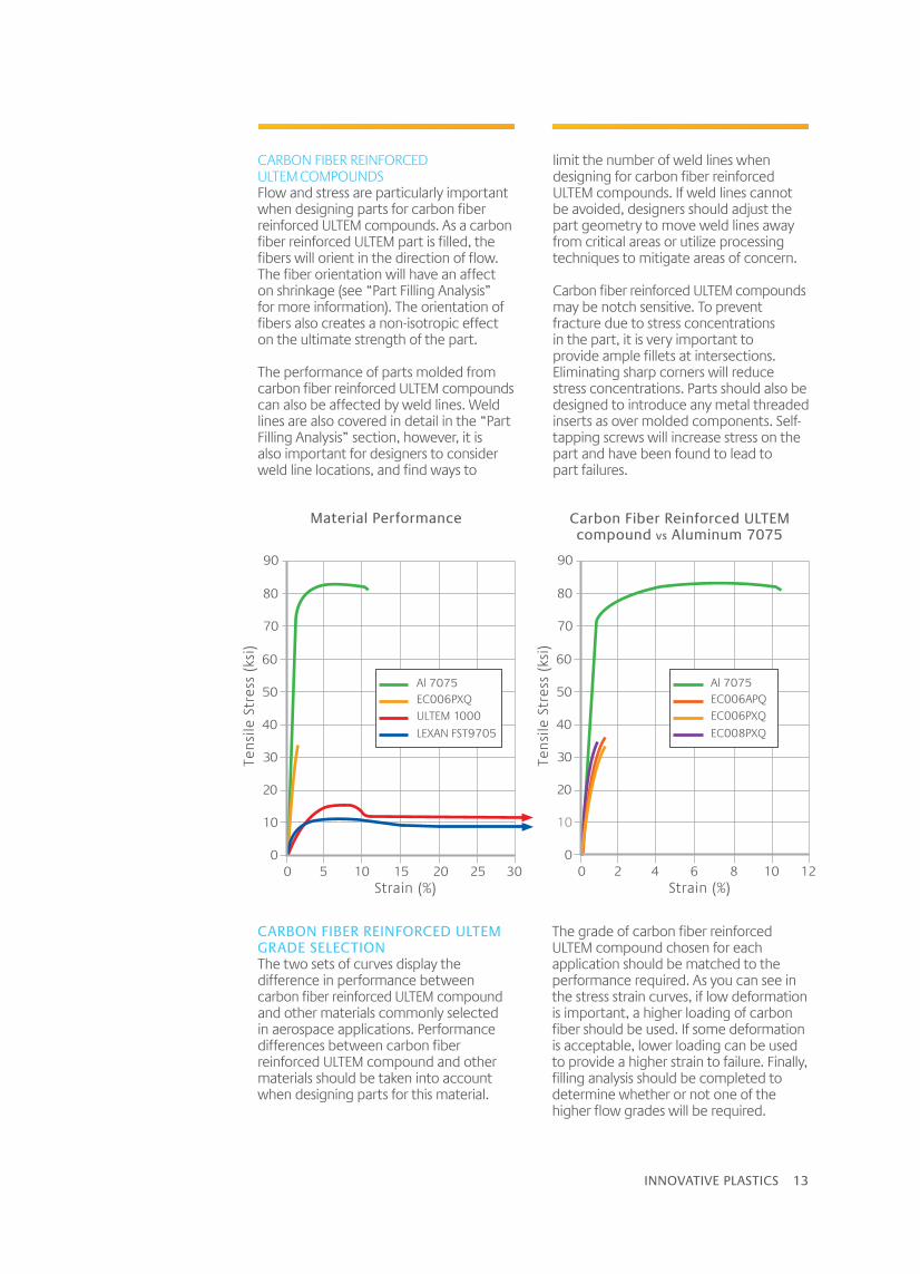
CARBON FIBER REINFORCED ULTEM COMPOUNDSFlow and stress are particularly important when designing parts for carbon fiber reinforced ULTEM compounds. As a carbon fiber reinforced ULTEM part is filled, the fibers will orient in the direction of flow. The fiber orientation will have an affect on shrinkage (see “Part Filling Analysis” for more information). The orientation of fibers also creates a non-isotropic effect on the ultimate strength of the part.
The performance of parts molded from carbon fiber reinforced ULTEM compounds can also be affected by weld lines. Weld lines are also covered in detail in the “Part Filling Analysis” section, however, it is also important for designers to consider weld line locations, and find ways to
limit the number of weld lines when designing for carbon fiber reinforced ULTEM compounds. If weld lines cannot be avoided, designers should adjust the part geometry to move weld lines away from critical areas or utilize processing techniques to mitigate areas of concern.
Carbon fiber reinforced ULTEM compounds may be notch sensitive. To prevent fracture due to stress concentrations in the part, it is very important to provide ample fillets at intersections. Eliminating sharp corners will reduce stress concentrations. Parts should also be designed to introduce any metal threaded inserts as over molded components. Self-tapping screws will increase stress on the part and have been found to lead to part failures.
CARBON FIBER REINFORCED ULTEM GRADE SELECTIONThe two sets of curves display the difference in performance between carbon fiber reinforced ULTEM compound and other materials commonly selected in aerospace applications. Performance differences between carbon fiber reinforced ULTEM compound and other materials should be taken into account when designing parts for this material.
The grade of carbon fiber reinforced ULTEM compound chosen for each application should be matched to the performance required. As you can see in the stress strain curves, if low deformation is important, a higher loading of carbon fiber should be used. If some deformation is acceptable, lower loading can be used to provide a higher strain to failure. Finally, filling analysis should be completed to determine whether or not one of the higher flow grades will be required.
Tens
ile S
tres
s (k
si)
Strain (%)0 5 10 15 20 25 30
60
50
40
30
20
10
0
80
90
70
Al 7075EC006PXQULTEM 1000
LEXAN FST9705
Tens
ile S
tres
s (k
si)
Strain (%)0 2 4 6 8 10 12
60
50
40
30
20
10
0
80
90
70
Al 7075EC006APQEC006PXQ
EC008PXQ
Material Performance Carbon Fiber Reinforced ULTEM compound vs Aluminum 7075

14 INNOVATIVE PLASTICS
PROCESSING GUIDEThe two main considerations when processing carbon fiber reinforced ULTEM compound are maintaining fiber length and preventing degradation of the ULTEM resin. Along with processing, it is also important to adjust part design, gate layout and tooling approach when working with carbon fiber reinforced ULTEM compound. Presented next are some guidelines to follow, and as always, it is best to work closely with your SABIC technical team on challenging applications.
PART FILLING ANALYSIS Part filling analysis is highly recommended when designing parts for carbon fiber reinforced ULTEM compound applications. Filling analysis is an excellent tool to optimize part geometry, predict weld line locations and estimate fill pressures.
During this phase of the design process, the optimal gate locations can be determined to ensure that weld lines are not likely to occur in high stress areas of the part and that the designated press will be capable of filling the part.

INNOVATIVE PLASTICS 15
SHRINKAGEWhen the melt cools, the fibers which are aligned in the direction of flow inhibit shrinkage in the direction of flow, but not in the transverse direction, resulting in non-uniform shrinkage. Anisotropic shrinkage is a major cause of part warpage in reinforced thermoplastics, and should be given special consideration during the design phase.
As you can see in the graphs below, carbon fiber reinforced ULTEM compounds (EC006PXQ) shrink far less than unfilled ULTEM resin (ULTEM 1000), and even less than glass fiber reinforced ULTEM resin (ULTEM 2300). The shrinkage for carbon fiber reinforced ULTEM compounds may range from -0.1% to 0.8%. As stated above, it is extremely important to consider this low shrinkage when choosing draft angles.
Sufficient draft angle will allow for easy removal of parts from the mold.
The low shrinkage may also pose problems when determining what side of the mold a part will stay on during the mold opening phase of the injection cycle. For example, a part will generally shrink tight enough around a standing core on the moveable side of a mold to keep it on that side when the mold opens. When using a resin that has little to no shrinkage, like carbon fiber reinforced ULTEM compounds, the shrinkage around a standing core may not be enough force to keep the molded part on the correct half of the mold.
Again, because the carbon fiber reinforced ULTEM compounds do not shrink as much as traditional resins, it is important to understand how the molded part may be affected and adjust the tooling approach accordingly. If possible, before cutting tooling, it will be informative to sample carbon fiber reinforced ULTEM compounds in similar molds.
ULTEM 1000 ULTEM 2300 EC006PXQ
.8
.7
.6
.5
.4
.3
.2
.1
0
-.1
-.2
Shri
nkag
e Pe
rcen
tag
e
Flow Direction 140mm Width Plaque
ULTEM 1000 ULTEM 2300 EC006PXQ
.8
.7
.6
.5
.4
.3
.2
.1
0
-.1
-.2
Shri
nkag
e Pe
rcen
tag
e
Cross Directional Flow 75mm Width Plaque
16 INNOVATIVE PLASTICS
WELD STRENGTHWeld lines form when flow fronts come together during the filling stage of molding. Depending on process conditions, weld line strength can vary significantly. Carbon fiber reinforced ULTEM compound is particularly prone to weakness at weld lines within the part because when the flow fronts reconnect, fibers are not able to cross the weld line. In these locations, the part strength may be as low as unfilled ULTEM resin. Awareness of weld line location is advisable, and avoidance in critical areas is suggested. If the part is not designed properly, weak weld lines can result in premature part failure.
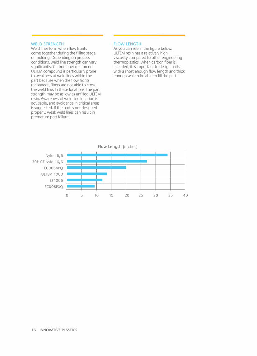
FLOW LENGTHAs you can see in the figure below, ULTEM resin has a relatively high viscosity compared to other engineering thermoplastics. When carbon fiber is included, it is important to design parts with a short enough flow length and thick enough wall to be able to fill the part.
Nylon 6/6
30% CF Nylon 6/6
EC006APQ
ULTEM 1000
EF1006
EC008PXQ
0 5 10 15 20 25 30 35 40
Flow Length (inches)

INNOVATIVE PLASTICS 17
GATINGGate design and layout should get a lot of attention during the mold design phase of any project using carbon fiber reinforced ULTEM compound.
The preferred gate design for carbon fiber reinforced ULTEM compound is a direct gate. This method provides the least restriction to flow, and can be located centrally in the part, which reduces the overall flow length required to fill the part. Direct gates should be located at the thickest section of the part, with their diameters twice the thickness of the section but no greater than ½ inch (12.7 mm) in diameter. Downsides to direct gating a part include higher likelihood of part distortion in rectangular shapes, increased probability of gate blush or sunburst effect and machine marks on part surfaces from gate removal.
Another good gate option for parts molded with carbon fiber reinforced ULTEM compound are edge gates. Edge gates also provide fewer flow restrictions than other types of gate, but are less likely to cause sunburst and help reduce part distortion caused by fiber orientation. The downsides to edge gating are generally decreased flow lengths and potential difficulties filling larger, thin walled parts. For optimum resin flow, the height or thickness of the gate should generally be 85 to 100% of the wall thickness up to 0.125 inch (3.2mm). The gate width should be two times the depth. A radius should be located at the junction of the molded part to prevent surface splay and to minimize molded in stresses.
HOT MANIFOLDSUse of hot feed system is relatively common in tools used for injection molded parts. However, due to high viscosity and high filler loadings, hot manifolds are not recommended when molding carbon fiber reinforced ULTEM compound.
If hot manifolds are used with such carbon filled materials, care has to be exercised while designing the hot feed system. A term called “residence time” is introduced here. This is the time the resin stays in the hot feed system until it enters the cavity while the resin is being filled, packed and cooled in the preceding cycle. If this time exceeds a particular value there could be degradation of the resin.
There is also the risk of carbonization of the resin due to the presence of carbon fibers in the resin. This has to be considered while designing and using a hot valve gate feed system. There is the risk of these small openings for the valve gates getting blocked due to the carbonization. Every time the mold is loaded onto the machine afresh, these openings will be closed and need good amounts of heating and purging of resin to open up, so that the valves can operate smoothly.
MOLD DESIGNProcessing carbon fiber reinforced ULTEM compound can be challenging if proper tooling design guidelines are not followed. Cycle time, molded-in stress and final part strength are all affected by decisions made during the tooling design phase of your project.
Parting Line
Nozzle Orifice
Direct Gate (Sprue)
Molded Part

18 INNOVATIVE PLASTICS
VENTINGVenting the mold cavity properly is imperative when molding carbon fiber reinforced ULTEM compound. Insufficient venting will restrict plastic flow and make it more difficult to fill the mold cavity. Full perimeter venting should be used whenever possible to avoid air entrapment at the parting line.
Some fill patterns may trap gasses in areas that cannot be vented at the parting line. To relieve these gasses, vents can be machined on ejector pins, sleeve ejectors and moving cores to allow venting through the mold.
COOLINGUniform temperature control of the molding surfaces is critical for optimizing cycle time and part properties. Ample coolant channels within the mold are required to run carbon fiber reinforced ULTEM compound. Typical channels are ½ inch or larger, 1 ½ to 2 inches apart and ½ inch below cavity or core surfaces. Coolant channels should follow the surface of the cavity or core as closely as possible. Poorly designed cooling channels can create a large temperature differential across the mold surface. This condition creates different cooling rates and results in molded-in stresses in the parts.
To improve the efficiency of thermolators, it is recommended that mold makers incorporate insulating sheets between the clamp plate and platens. Insulating sheets can also be used behind the cavity plates to further improve efficiency. During processing, it is important to monitor mold surface temperature along with coolant supply and return temperatures to ensure part quality and consistency from run to run.
EJECTIONDraft should be included on all surfaces in the line of draw. Normally, the greater the draft angle, the easier it is to eject the part from the mold. Draft is particularly important for parts molded in carbon fiber reinforced ULTEM compound because they will experience little to no shrinkage during the mold cooling phase. It is recommended that parts be designed to include draft angles of 3° or more when using carbon fiber reinforced ULTEM compound. In certain cases, if low draft angles are required, the use of various tool plating processes can aid in part ejection.
The low shrinkage experienced by carbon fiber reinforced ULTEM compound also requires sufficient ejection area to push the part off of the mold. The use of stripper plates is the most preferred method of part ejection because of the large contact area. If knockout pins are used, it is important to use an ample number of knockout pins. The pins should be designed with sufficient area to avoid compressing the resin surface and be located so that they do not induce stress in the part.

INNOVATIVE PLASTICS 19
CLAMP TONNAGEClamp tonnage required should be calculated on the side of caution due to the high injection pressure generated by higher viscosity material and its resistance to flow. Carbon fiber reinforced ULTEM compound will require a minimum of 5 – 7 tons /in² (69-97 MPa).
BARREL / SCREWSelect a barrel size that employs no more than 40 – 60% of the barrel’s overall rated capacity. Keep in mind that the calculation must be converted to reflect the high density of the carbon fiber reinforced ULTEM compound. Other guidelines when selecting a screw and barrel include:
A single-stage plasticizing unit that has a balance between resistance to high wear conditions and corrosion. A CPM9V screw with a bimetallic barrel is a common choice for the material of construction.
A square pitch screw having a minimum of 18:1 L/D is suggested, however the preferred minimum would be 20:1 with a compression ratio range of 2.0:1 to 2.3:1.
The preferred screw design will maintain fiber length and minimize shear heating. A general purpose design with a minimum of 6 feed flights, 5 compression flights and 4 metering flights or a 6-5-4 design is ideal for 2-2.3:1 compression ratio screws.
Injection screws can be coated with UCAR†, Kennametal Stellite† or Colmonoy† on screw flights for additional protection. Note Stellite #6 is not to be used due to galling in the barrel.
Screw flights should not be chrome plated since reinforced or filled composites will abrade or chip the plating in a short period of time.
A minimum of three separate controlled barrel heating zones should be employed with a separate control of the nozzle.
Three-piece “free flow” type check rings utilizing a fully fluted tip are recommended. The free flow non-return valve provides an unrestricted flow and no “deadspots” within the tip. Ball checks and positive shut-offs are not recommended when processing carbon fiber reinforced ULTEM compound due to the restrictive nature of their design. AVAILABLE INJECTION PRESSUREHigh injection pressure and speeds will be encountered while producing parts from carbon fiber reinforced ULTEM compound. The injection molding machine should be closely specified or upgraded to accommodate carbon.
MACHINE SPECIFICATIONS CONSIDERATIONSWhen using carbon fiber reinforced ULTEM compound, special consideration needs to be given to key elements of the molding equipment.
In-line reciprocating screw injection molding machines are best for maintaining homogeneity of the melt and providing a stable environment for reduced residence time of the compound. Optimum part quality is achieved with good barrel and temperature management. Injection molding machines with close loop (pid) temperature control should be utilized whenever possible.

20 INNOVATIVE PLASTICS
NOZZLE DESIGNNozzles should be as short as possible and offer an unrestricted flow path. An open channel (full bore) design is preferred over a tapered channel (nylon type nozzle). Nozzle exit land L/D should be a ratio of 1:1. Positive shutoff nozzles can be used, however flow spring type designs should be avoided. If a shutoff nozzle is specified, the shutoff pin must be perpendicular to the flow direction of the melt and unrestricted in the open position. Contact your SABIC technical team for more information on approved shutoff nozzles for carbon fiber reinforced ULTE compounds. The nozzle opening should be no less than .187in or (4.75mm) and no smaller than 20% of the opening in the sprue bushing. Nozzles should be equipped with a full-length heater band and a spate thermocouple. Variac type controls are not recommended due to lack of accuracy. PID controls with auto tuning features are highly recommended.
MOLD TEMPERATURE CONTROLAccurate control of the mold cavities is important and has direct influence on the production of quality molded parts. Separate control of each half of the mold is ideal. Conventional water-cooling systems are not capable of reaching the recommended mold temperatures.
Oil heating or high pressure water systems are required to reach surface tool temperatures of 350 – 400°F (177-200°C) required for carbon fiber reinforced ULTEM compounds. (See carbon fiber reinforced ULTEM compound datasheets for grade-specific processing guidelines.) It is not advisable to use electric cartridge heaters because they do not provide cooling capacity to remove heat from the mold which often results in poor temperature control. Low mold temperatures or rapid cooling of the melt could promote unwanted defects such as molded-in stress, degree of orientation, post molding shrinkage, warpage and poor part surface.
MATERIAL HANDLING AND DRYINGCarbon fiber reinforced ULTEM compound requires thorough drying prior to injection molding to assure maximum properties in the molded part. Four to six hours of drying at 300°F (150°C) in a dry air dryer with a dew point of -40°F is the recommended drying time for carbon fiber reinforced ULTEM compounds. When molding, the measured moisture content should be at or below 0.02%.
A machine mounted dehumidifying hopper with a closed loop control circulating air system is preferred to maintain consistency in the moisture level during production runs. If bulk drying is employed, ensure that the hopper dryer unit is equipped with a diffuser cone to deliver proper distribution of air flow throughout the hopper. Carbon fiber reinforced ULTEM compounds are readily conveyed via vacuum hopper loaders. MACHINE PREPARATIONAlthough carbon fiber reinforced ULTEM compound is considered a high-temperature thermoplastic, the required processing temperatures are lower than other high temperature products such as PES and PEEK. Prior to introducing carbon fiber reinforced ULTEM compound to the molding machine barrel, the screw and barrel must be thoroughly cleaned. To clean a screw and barrel, purge completely with low-temperature, then middle-temperature and finally high-temperature unfilled resins. For example, polypropylene, LEXAN and ULTEM resins could be used. Before moving to the next resin, check the air shot for evidence of contamination. If contamination cannot be cleared through purging, it is necessary to remove the screw and clean both the screw and barrel. When shutting down for extended periods of time or switching to a new resin, it is important to run through the same procedure in the reverse order when lowering barrel temperatures. Not following this procedure could lead to extensive machine damage.
INNOVATIVE PLASTICS 21
START-UP PARAMETERSTypical start-up processing conditions are provided by a commercial datasheet available online at www.sabic-ip.com or contacting your local technical process development engineer. The processing range for carbon fiber reinforced ULTEM compound is 730–760°F (370–400°C).
Set screw rpm to be within the cycle of your process. Excessive screw speed will damage carbon fibers. A fast injection rate will promote the best surface finish in carbon fiber reinforced compounds. Cavities should be filled as rapidly as possible to minimize fiber orientation and enhance weld-line integrity. Mechanical properties of reinforced compounds are optimized by packing the part as much as possible.
Higher than average mold surface temperatures should be used to maximize flow length and obtain a good surface finish. A hotter mold can be maintained for a reinforced compound without lengthening the cycle. When running a new tool for the first time with a carbon fiber reinforced ULTEM compound, always start with less than maximum pressure and limit the shot size to avoid over packing the part.
INJECTION PRESSURE / SPEEDAs mentioned above in the machine consideration section, injection pressures of 35–40,000 psi (2450–2750 MPa) are not uncommon and can be a normal operating range for carbon fiber reinforced ULTEM compound. Keep in mind that these ranges can be lower or adjusted based on part geometry and/or tool design. First-stage pressure influences the surface quality, orientation and mechanical stresses of the melt, therefore a properly designed machine and mold to allow for 98% percent of the part on first stage is highly recommended. Holding pressure in the range of 50–75% of first-stage pressure will provide compression of the melt in the cavity for replication of the mold surface. Holding pressure should be set just high enough in order to prevent voids, sink marks and control shrinkage.
BACK PRESSUREScrew back pressure should be kept as low as possible with 25–50 psi (170-345 kPA) usually being sufficient. The back pressure serves to displace air in the screw feed section, improve melt homogeneity and facilitate heating of the melt. Adjustments to the back pressure will be apparent in the stock temperature developed. A surplus of back pressure will result in overheating of the melt and excessive fiber breakage. CUSHIONA minimal amount of cushion should be provided. Cushion should be set to 10% of the screw diameter to allow for adequate compensation of shot-to-shot variation. A minimal amount of cushion will also provide better pressure transfer on the melt, minimize over packing and prevent excessive sinks and voids. SCREW SPEEDA screw speed between 30–60 rpm is sufficient for most carbon fiber reinforced ULTEM compound. Slightly higher rotation speeds can be used for small diameter <1.5in (38mm) screws. Optimum screw speed selection can be reached by adjusting screw return stoppage to occur just prior to the mold open sequence. High screw speeds can result in over heating of the melt and increased residence time in the molding machine. CYCLE / RESIDENCE TIMECycle time should be kept to a minimum or on an “as needed” basis to maintain optimum cycle time and quality parts. Carbon fiber reinforced ULTEM compound is very stable, however extended residence times over 10 minutes should be avoided. As mentioned above in the machine considerations section, sizing of barrel and screw is critical. Target range of barrel capacity utilization should be 40 – 60%.
INJECTION MOLDING PROCESSING

22 INNOVATIVE PLASTICS
The value we offer begins with our commitment to drive the success of our customers. We’re here to support – on the ground, in the air and for the long run. We understand that the advanced materials we provide are only as good as the innovations they empower the industry to implement.
That’s why SABIC resources, like the Global Application Technology
organization, are ready to assist – positioned around the world to help turn your best ideas and market challenges into business advantages. And to make the skies safer and more profitable.
A GLOBAL PARTNER
SABIC Global Headquarters (1)
Technology Centers (12)
Application Centers (4)
SABIC Corporate Research and Innovation Center (1)
Distribution, Storage Facilities and Logistical Hubs (51)
(84)
Manufacturing and Compounding Companies (60)

INNOVATIVE PLASTICS 23
With more than 90 manufacturing, technology and joint venture facilities, SABIC is located where you are, offering the full benefit of our capabilities – from application development to technology solutions to logistic support.
Together we can redefine the limits of performance, safety and compliance and help shape the aircraft industry of tomorrow.
SABIC Global Headquarters (1)
Technology Centers (12)
Application Centers (4)
SABIC Corporate Research and Innovation Center (1)
Distribution, Storage Facilities and Logistical Hubs (51)
(84)
Manufacturing and Compounding Companies (60)

SABIC-PLA-8850-ENwww.sabic-ip.com
DISCLAIMER: THE MATERIALS, PRODUCTS AND SERVICES OF SAUDI BASIC INDUSTRIES CORPORATION (SABIC) OR ITS SUBSIDIARIES OR AFFILIATES (“SELLER”) ARE SOLD SUBJECT TO SELLER’S STANDARD CONDITIONS OF SALE, WHICH ARE AVAILABLE UPON REQUEST. INFORMATION AND RECOMMENDATIONS CONTAINED IN THIS DOCUMENT ARE GIVEN IN GOOD FAITH. HOWEVER, SELLER MAKES NO EXPRESS OR IMPLIED REPRESENTATION, WARRANTY OR GUARANTEE (i) THAT ANY RESULTS DESCRIBED IN THIS DOCUMENT WILL BE OBTAINED UNDER END-USE CONDITIONS, OR (ii) AS TO THE EFFECTIVENESS OR SAFETY OF ANY DESIGN OR APPLICATION INCORPORATING SELLER’S MATERIALS, PRODUCTS, SERVICES OR RECOMMENDATIONS. UNLESS OTHERWISE PROVIDED IN SELLER’S STANDARD CONDITIONS OF SALE, SELLER SHALL NOT BE RESPONSIBLE FOR ANY LOSS RESULTING FROM ANY USE OF ITS MATERIALS, PRODUCTS, SERVICES OR RECOMMENDATIONS DESCRIBED IN THIS DOCUMENT. Each user is responsible for making its own determination as to the suitability of Seller’s materials, products, services or recommendations for the user’s particular use through appropriate end-use and other testing and analysis. Nothing in any document or oral statement shall be deemed to alter or waive any provision of Seller’s Standard Conditions of Sale or this Disclaimer, unless it is specifically agreed to in a writing signed by Seller. Statements by Seller concerning a possible use of any material, product, service or design do not, are not intended to, and should not be construed to grant any license under any patent or other intellectual property right of Seller or as a recommendation for the use of any material, product, service or design in a manner that infringes any patent or other intellectual property right.
SABIC and brands marked with ™ are trademarks of SABIC or its subsidiaries or affiliates.© 2014 Saudi Basic Industries Corporation (SABIC). All Rights Reserved.
† Any brands, products or services of other companies referenced in this document are the trademarks, service marks and/or trade names of their respective holders.
CONTACT USMiddle East and AfricaSABIC Global HeadquartersPO Box 5101Riyadh 11422Saudi ArabiaT +966 (0) 1 225 8000F +966 (0) 1 225 9000E [email protected]
Americas1 Plastics AvenuePittsfield, MA 01201USAT +1 413 448 7110F +1 413 448 5573
Technical Answer CenterT +1 800 845 0600
EuropePlasticslaan 1PO Box 1174600 AC Bergen op ZoomThe NetherlandsT +31 164 292911F +31 164 292940
Technical Answer CenterT (0) 0 800 1 238 5060T2 00 36 1 238 5060E [email protected]
Asia Pacific2550 Xiupu RoadPudong201319 ShanghaiChinaT +86 21 2037 8188F +86 21 2037 8288