inoui innovative operational uas integration filepu public x pp restricted to other programme...
TRANSCRIPT
Contract no.: TREN/07/FP6AE/S07.69061/037191
INOUI INNOVATIVE OPERATIONAL UAS INTEGRATION
Instrument: STREP (Specific Targeted Research Project)
Thematic Priority: AERO-2005-4.g Open Upstream Research
D5.3 “TOWARDS SAFETY REQUIREMENTS FOR THE INTEGRATION OF UAS IN NON-SEGREGATED AIRSPACE”
Due date of deliverable: 09/11/2009 Actual submission date: 15/12/2009
Start date of project: 09/10/2007 Duration: 29 months
Organisation name of lead for this deliverable: ONE/DFS
Revision: Version 1.0
Approval status
Author Verification Authority Project Approval Michel Lemoine (ONERA), Carlos Montes (BR&TE), Cristina Martinez and Jorge Bueno (ISDEFE), Hans de Jong (DFS)
Hans de Jong (DFS) Achim Baumann (DFS)
WP5.3 participants WP5 leader PCO
16/11/2009 30/11/2009 15/12/2009
Project co-funded by the European Commission within the Sixth Framework Programme (2002-2006)
Dissemination Level PU Public X
PP Restricted to other programme participants (including the Commission Services)
RE Restricted to a group specified by the consortium (including the Commission Services)
CO Confidential, only for members of the consortium (including the Commission Services)


Title: D5.3 “Towards Safety Requirements” Date: 15/12/2009 Document ID: INOUI_WP5.3_ONE-DFS_D5.3_PU_V1.0.doc Revision: Version 1.0
Innovative Operational UAS Integration
- 3 - PU
This project has been carried out under a contract awarded by the European Commission. No part of this report may be used, reproduced and/or disclosed in any form or by any means without the prior written permission of the INOUI project partners. © 2009 – All rights reserved
Contributing Partner Company Name DFS Hans de Jong, Dirk Pulver, Michael Teichmann ISDEFE Jorge Bueno, Cristina Martinez BR&TE Carlos Montes ONERA Michel Lemoine RDE Klaus Wohlers
Distribution List Company Name Company Name European Commission Gilles Fartek DFS Achim Baumann BR&TE Carlos Montes Marita Lintener Marisol de Mena Serrano Stefan Tenoort Hans de Jong RDE Klaus Wohlers John Tattersall ONERA Michel Lemoine ISDEFE Jorge Bueno Claude Le Tallec Cristina Martinez Antoine Joulia Juan Alberto Herrería INAXIS Paula Lopez-Catala
Document Change Log Rev. Edition
date Author Modified
Sections/Pages Comments
0.1 22/08/2009 Michel Lemoine (ONERA)
All
0.2 16/10/2009 Michel Lemoine (ONERA), Carlos Montes (BR&TE), Cristina Martinez and Jorge Bueno (ISDEFE) and Hans de Jong (DFS)
All Results of workshop on 28 September 2009 incorporated.
0.3 13/11/2009 Michel Lemoine (ONERA) and Hans de Jong (DFS)
All Several small changes.
1.0 30/11/2009 Hans de Jong (DFS) All Minor corrections. Version for submission to EC
Title: D5.3 “Towards Safety Requirements” Date: 15/12/2009
Document ID: INOUI_WP5.3_ONE-DFS_D5.3_PU_V1.0.doc
Innovative Operational UAS Integration
Revision: Version 1.0
PU - 4 -
This project has been carried out under a contract awarded by the European Commission. No part of this report may be used, reproduced and/or disclosed in any form or by any means without the prior written permission of the INOUI project partners. © 2009 – All rights reserved
Contents
1 Introduction ........................................................................................................................... 7
1.1 Background...................................................................................................................... 7
1.2 Purpose of the Document................................................................................................. 7
1.3 Document Structure ......................................................................................................... 8
1.4 Applicable and Reference Documents.............................................................................. 8
1.5 Glossary..........................................................................................................................11
2 Approach ..............................................................................................................................13
3 Ideas and justifications for Safety Requirements ..............................................................15
3.1 Scenario 1a – High performance UAS in high density airspace.......................................16
3.1.1 Ideas and justifications for Safety Requirements for Failure modes ....................................... 16
3.1.2 Ideas and justifications for Safety Requirements for Hazards................................................. 19
3.1.3 Out-of-the-box Ideas and justifications for Safety Requirements ............................................ 23
3.2 Scenario 2 – Low performance UAS in low density airspace ...........................................25
3.2.1 Ideas and justifications for Safety Requirements for Failure modes ....................................... 25
3.2.2 Ideas and justifications for Safety Requirements for Hazards................................................. 29
3.2.3 Out-of-the-box Ideas and justifications for Safety Requirements ............................................ 31
4 Example of a formal method to obtain Safety Requirements............................................32
4.1 Comparing Safety Requirements for Scenarios 1a and 2 ................................................32
4.2 Validation of Safety Requirements ..................................................................................32
4.3 Fixing failures: using formal methods ..............................................................................32
4.3.1 Fixing failure f1 “UA leaves cleared/planned route”................................................................. 33
4.3.2 Fixing all the failures ................................................................................................................ 35
5 Summary and Conclusions .................................................................................................36

Title: D5.3 “Towards Safety Requirements” Date: 15/12/2009 Document ID: INOUI_WP5.3_ONE-DFS_D5.3_PU_V1.0.doc Revision: Version 1.0
Innovative Operational UAS Integration
- 5 - PU
This project has been carried out under a contract awarded by the European Commission. No part of this report may be used, reproduced and/or disclosed in any form or by any means without the prior written permission of the INOUI project partners. © 2009 – All rights reserved
List of Figures
Figure 1: State machine associated to hazard h1..................................................................................... 34

Title: D5.3 “Towards Safety Requirements” Date: 15/12/2009
Document ID: INOUI_WP5.3_ONE-DFS_D5.3_PU_V1.0.doc
Innovative Operational UAS Integration
Revision: Version 1.0
PU - 6 -
This project has been carried out under a contract awarded by the European Commission. No part of this report may be used, reproduced and/or disclosed in any form or by any means without the prior written permission of the INOUI project partners. © 2009 – All rights reserved
List of Tables
Table 1: Applicable and Reference Documents.......................................................................................... 8

Title: D5.3 “Towards Safety Requirements” Date: 15/12/2009 Document ID: INOUI_WP5.3_ONE-DFS_D5.3_PU_V1.0.doc Revision: Version 1.0
Innovative Operational UAS Integration
- 7 - PU
This project has been carried out under a contract awarded by the European Commission. No part of this report may be used, reproduced and/or disclosed in any form or by any means without the prior written permission of the INOUI project partners. © 2009 – All rights reserved
1 Introduction
The overall objective of INOUI is to assess different domains of the ATM system of today and 2020 to develop a roadmap how to integrate UAS into the operational concept for the future. This activity will complement the activities of the SESAR definition phase and fill the gaps with regard to some specifications of UAS.
1.1 Background
“Innovative Operational UAS Integration” (INOUI) is a “Specific Targeted Research Project” supported by the European Commission Directorate General "Transport and Energy" within the 6th Framework Programme in response to Call 4 of the Thematic Priority Aeronautics and Space, Research Area 1.3.1, Innovative air traffic management research, Research Domain 4.g., ATM for new vehicles.
The main objective of the INOUI project is to provide a roadmap to the future of UAS in the context of the ever changing ATM environment. In this respect, INOUI aims at complementing the SESAR activities with regard to the operational concept and the architecture as well as the roadmap for Research and Development activities. In particular the different tasks are aiming at:
Identifying the spread of operational concepts for UAS applications and describe the resulting procedures and requirements in the different timeframes up to 2020;
Identify how UAS can fit into the ATM System of 2020 and what activities have to be taken especially from the UAS point of view (research roadmap);
Identifying existing certification requirements and processes, and suggest an optimum certification blueprint for human resources and, as far as required, UAS related technologies;
Identify how UAS can benefit from SWIM and what activities have to be taken to achieve the benefit;
Identify the safety issues related to UAS and develop high level Safety Objectives and Requirements; and
Identify the potential airport types for UAS operations and describe the operational impact.
The INOUI project is planned for 2 years duration and the work will be conducted by a consortium formed of 6 partners from France, Germany and Spain.
1.2 Purpose of the Document
The INOUI project consists of seven work packages, of which the fifth (WP5) is entitled “Safety Analysis”. WP5 includes six sub packages:
WP5.0 Safety Criteria; WP5.1 System Description for Safety Analysis; WP5.2 Identification of Hazards and Safety Objectives; WP5.3 Analysis of hazards and identification of Safety Requirements; WP5.4 Aerodrome Safety Analysis; and
Title: D5.3 “Towards Safety Requirements” Date: 15/12/2009
Document ID: INOUI_WP5.3_ONE-DFS_D5.3_PU_V1.0.doc
Innovative Operational UAS Integration
Revision: Version 1.0
PU - 8 -
This project has been carried out under a contract awarded by the European Commission. No part of this report may be used, reproduced and/or disclosed in any form or by any means without the prior written permission of the INOUI project partners. © 2009 – All rights reserved
WP5.5 Interpreting the Safety Analysis in the context of SESAR.
The purpose of this document is to document the results of WP5.3 in form of the deliverable D5.3.
1.3 Document Structure
The present document is divided into the following sections:
Section 1 “Introduction” (the present section) introduces the reader to INOUI, the various tasks within the INOUI Safety Analysis work package and the structure of this document and it contains the reference documents and a glossary;
Section 2 “Approach” indicates the input to the task reported in the present document and the approach towards Safety Requirements;
Section 3 “Ideas and justifications for Safety Requirements” contains the results of the working sessions in which the first steps towards Safety Requirements for two scenarios for integrating UAS in non-segregated controlled airspace are made;
Section 4 “Example of a formal method to obtain Safety Requirements” presents an example of the application of a more formal methodology to derive Safety Requirements; and
Section 5 “Summary and Conclusions” summarises and concludes this document.
1.4 Applicable and Reference Documents
A reference of the documents used in the course of this working package has been included in the table below. With a few exceptions, the documents are publicly accessible. The restricted documents have been indicated for completeness.
Table 1: Applicable and Reference Documents

Title: D5.3 “Towards Safety Requirements” Date: 15/12/2009 Document ID: INOUI_WP5.3_ONE-DFS_D5.3_PU_V1.0.doc Revision: Version 1.0
Innovative Operational UAS Integration
- 9 - PU
This project has been carried out under a contract awarded by the European Commission. No part of this report may be used, reproduced and/or disclosed in any form or by any means without the prior written permission of the INOUI project partners. © 2009 – All rights reserved
N° Title Reference Date [1] Annexes “Generic UAS ATM Safety Assessment
Baseline Scenario 1/UAS – IFR Operations In Classes A, B or C/En Route Airspace” and “Generic UAS ATM Safety Assessment Baseline Scenario 2/UAS – VLOS”
EUROCONTROL Task Requirement Sheet #: 08-112565-T
03/10/2008
[2] Commission Regulation (EC) 2096/2005 Official Journal of the European Union 20/12/2005
[3] Contract No TREN/07/FP6AE/S07.69061/037191 regarding the project “Innovative Operational UAV Integration INOUI" between the European Commission and DFS Deutsche Flugsicherung, signed in August 2007
2005-157_FP6_UAV_Contract_signature.pdf
August 2007
[4] DFS Safety Assessment Handbook, Edition 2.01, 7th November 2005
Restricted document 07/11/2005
[5] Draft for INOUI D5.3 “INOUI Safety Requirements”, Michel Lemoine (ONERA)
Version 0.1 22/08/2009
[6] EUROCONTROL Safety regulatory Requirement ESARR 4, Risk Assessment and Mitigation in ATM, Edition 1.0, 5 April 2001
http://www.EUROCONTROL.int/src/gallery/content/public/documents/deliverables/esarr4v1.pdf
05/04/2001
[7] EUROCONTROL Simulation Report for the UAS Simulation 2008 project, Edition 2.0 06/02/2009
[8] European Aviation Safety Agency Policy, Airworthiness certification of Unmanned Aircraft Systems (UAS)
EASA Policy Statement Doc # E.Y01301
25/08/2009
[9] Final Report for the Draft Implementing Rule on Performance Review, Catherine Hennessy
http://www.eurocontrol.int/ses/public/standard_page/sk_perf_review.html
March 2007
[10] IFATS, Innovative Future Air Transport System European Project, 6th PCRD
http://www.ifats-project.org/ 2005-2007
[11] INOUI D1.1 – Definition of the UAV environment INOUI-WP1.1-DFS-D1.1-CO-v1.0 29/02/2008
[12] INOUI D1.2 – Concept for Civil UAS Applications INOUI-WP1.1-D1.2-DFS-PU-V1.0 27/05/2008
[13] INOUI D1.3 – Proposal for the Integration of UAS into the Civil Airspace
INOUI-WP1.3-D1.3-DFS-PU-V1.0 01/03/2009
[14] INOUI D2.1 – Report on Technology Systems Solutions
27/02/2009
[15] INOUI D3.1: Regulatory Aspects for UAS Operations, Operators And Personnel Qualification
INOUI_WP3.1_ISD_D3.1_PU_v1.0.doc 05/06/2009
[16] INOUI D4.1 – Research Report “Elements of the UAV systems within the 2020 SWIM-enabled ATM”
INOUI-WP4.1-BRT-D-UAS in a SWIM enabled environment-PU-v2.pdf
[17] INOUI D4.2 – Research report describing the new UAS-related COP Actors
27/02/2009
[18] INOUI D5.0 – Safety Criteria INOUI-WP5-D5.0-DFS-PU-v2.0.pdf 03/04/2009

Title: D5.3 “Towards Safety Requirements” Date: 15/12/2009
Document ID: INOUI_WP5.3_ONE-DFS_D5.3_PU_V1.0.doc
Innovative Operational UAS Integration
Revision: Version 1.0
PU - 10 -
This project has been carried out under a contract awarded by the European Commission. No part of this report may be used, reproduced and/or disclosed in any form or by any means without the prior written permission of the INOUI project partners. © 2009 – All rights reserved
N° Title Reference Date [19] INOUI D5.1 – System Description for Safety
Analysis INOUI-WP5-D5.1-BRT-PU-V2.0 05/06/2009
[20] INOUI D5.2 – Functional Hazard Analysis INOUI_WP5_DFS_D5.2_PU_V1.0.doc 29/06/2009
[21] INOUI, Annex I to Contract – “Description of Work” 2005
2005-157_FP6_UAV_Contract_signature.pdf
10/04/2007
[22] INOUI, Consortium Agreement 2005-157_INOUI_CA_final_071009_final.pdf
07/10/2007
[23] Minutes of INOUI WP5.3 and WP5.5 Meeting on 28 and 29 September 2009, DFS, Langen
Version 0.1 06/10/2009
[24] Object Oriented Development: The Fusion Method, D. Coleman et al.
PRENTICE Hall 1997
[25] Recommendations for INOUI WP5 Scenario 1a and 2, Dirk Pulver and Michael Teichmann, DFS
Internal note sent to Hans de Jong (DFS) 24/09/2009
[26] Requirements Engineering: From System Goals to UML Models to Software Specifications, Axel van Lamsweerde
Wiley and Sons January 2009
[27] Rules of Air, Annex II 10th edition, ICAO July 2005
[28] Scenario Languages: Using Partial Orders to Model, Verify and Supervise Distributed and Concurrent Systems. Th. Gazagnaire
Ph. D. Thesis March 2008
[29] Specifications for the Use of Military UAVs as Operational Air Traffic Outside Segregated Airspace, EUROCONTROL, Ed. 1.0
Document Identifier: Eurocontrol-Spec-0102
26/07/2007
[30] SRC Policy Document 2, Use of Safety Nets in Risk Assessment & Mitigation in ATM, Safety Regulation Commission EUROCONTROL
http://www.EUROCONTROL.int/src/gallery/content/public/documents/deliverables/esarr4_awareness_package/srcpoldoc2_e10_ri_no_signatures.pdf
28/04/2003
[31] Unified Modeling Language, Resource Page http://www.uml.org/
[32] VUSIL (Validierung von UAS zur Integration in den Luftraum) Abschlussbericht,
DFS Deutsche Flugsicherung, Edition 0.8 20/02/2009
[33] WASLA/HALE – UAV Demonstrator Programme, Phase 3, Final Report, DFS
2007
[34] Formal Methods and their Role in the Certication of Critical Systems, John Rushby, Computer Science Laboratory
SRI International, Menlo Park, Technical Report CSL-95-1
March 1995
[35] Ecological Approach to Pilot Terrain Awareness C. Borst, Ph. D. Thesis, Delft University June 2009
[36] Air Traffic Management ICAO Doc 4444, 15th Edition 2007
[37] Aeronautical Telecommunications, Procedures including those with PANS status
ICAO Annex 10.. Volume II October 2001
Title: D5.3 “Towards Safety Requirements” Date: 15/12/2009 Document ID: INOUI_WP5.3_ONE-DFS_D5.3_PU_V1.0.doc Revision: Version 1.0
Innovative Operational UAS Integration
- 11 - PU
This project has been carried out under a contract awarded by the European Commission. No part of this report may be used, reproduced and/or disclosed in any form or by any means without the prior written permission of the INOUI project partners. © 2009 – All rights reserved
N° Title Reference Date [38] Modelo Integrado de Capacidad Leticia Biescas and Sara Peces, MICA
project. ISDEFE document 2004-2009
[39] Definition of the FRF environment SOFIA Consortium. European SOFIA project, D1.1
28/04/2007
[40] INOUI D2.2 – Assessment of Technology for UAS Integration
INOUI-WP2.2-ISD-PU-D2.2-v1.0 25/05/2009
[41] UAS Sim 2008 Project. Simulation Report v2.0. LFV and SAAB
06/02/2009
1.5 Glossary Abbreviation Full text 4D Four Dimensional ACAS Airborne Collision Avoidance System ASAS Airborne Separation Assistance System ACC Area Control Centre ADS-B Automatic Dependent Surveillance Broadcast ANS Air Navigation Service ANSP Air Navigation Service Provider AOC Airline Operations Centre APP Approach Control (Office/Service/Unit) ASAS Airborne Separation Assistance System ATC Air Traffic Control ATCO Air Traffic Controller ATM Air Traffic Management ATTAS Advanced Technologies Testing Aircraft System BLOS Beyond Line of Sight BRT Boeing R&T Europe C2 Command and Control CDTI Cockpit Display of Traffic Information CFIT Controlled Flight into Terrain CNS Communication Navigation and Surveillance CoA Certificate of Airworthiness COM Communication(s) CS Control Station DFS Deutsche Flugsicherung EASA European Aviation Safety Agency EC European Commission ECAC European Civil Aviation Conference ESARR EUROCONTROL Safety Regulatory Requirement EUROCAE European Organisation for Civil Aviation Electronics EUROCONTROL European Organisation for the Safety of Air Navigation FHA Functional Hazard Analysis
Title: D5.3 “Towards Safety Requirements” Date: 15/12/2009
Document ID: INOUI_WP5.3_ONE-DFS_D5.3_PU_V1.0.doc
Innovative Operational UAS Integration
Revision: Version 1.0
PU - 12 -
This project has been carried out under a contract awarded by the European Commission. No part of this report may be used, reproduced and/or disclosed in any form or by any means without the prior written permission of the INOUI project partners. © 2009 – All rights reserved
Abbreviation Full text FMS Flight Management System FRF Flight Reconfiguration Function HW Hardware ICAO International Civil Aviation Organization IFR Instrumental Flight Rules INOUI Innovative Operational UAS Integration ISD ISDEFE IT Information Technology JAR Joint Aviation Requirements LOS Line of Sight MSA Minimum Safe Altitude NAV Navigation n. a. Not applicable NOTAM Notice to Airmen ONE ONERA PIC Pilot in command PNF Pilot non flying RAMSYS DFS-tool/ system to support safety assessments RDE Rheinmetall Defence Electronics S&A Sense and Avoid SAM Safety Assessment Methodology SAMTF Safety Assessment Methodology Task Force SESAR Single European Sky ATM Research SR Safety Requirements SW Software SWIM System Wide Information Management TBC To be confirmed TBD To be defined TCAS Traffic Collision Avoidance System TMA Terminal Control Area TWR Aerodrome Control Tower UA Unmanned Aerial Vehicle UAS Unmanned Aerial Systems UAV Unmanned Aerial Vehicle UHF Ultra-High Frequencies UML Unified Modelling Language VFR Visual Flight Rules VHF Very High Frequency VUSIL “Validierung von UAS zur Integration in den Luftraum”, Validation of UAS for
integration into airspace WASLA/HALE Weitreichendes abbildendes luftgestütztes Aufklärungssystem/High Altitude Long
Endurance WP Work Package

Title: D5.3 “Towards Safety Requirements” Date: 15/12/2009 Document ID: INOUI_WP5.3_ONE-DFS_D5.3_PU_V1.0.doc Revision: Version 1.0
Innovative Operational UAS Integration
- 13 - PU
This project has been carried out under a contract awarded by the European Commission. No part of this report may be used, reproduced and/or disclosed in any form or by any means without the prior written permission of the INOUI project partners. © 2009 – All rights reserved
2 Approach
The present document INOUI D5.3 “Towards Safety Requirements for the Integration of UAS in non-segregated airspace” provides the next step in a safety assessment after the INOUI deliverables
INOUI D5.1 [19], which has presented the system description for two scenarios for integration of UAS in non-segregated controlled airspace; and
INOUI D5.2 [20] “Functional Hazard Analysis” presenting Safety Objectives and for each of these an Interpretation how hard it would be to achieve for both of the scenarios.
Indeed, the contents of INOUI D5.1 and D5.2, and in particular the scenarios developed, the assumptions made and results achieved, fully apply for the present document, as well.
The present document INOUI D5.3 aims to provide Safety Requirements for both of the scenarios and for each of the Safety Objectives identified for these.
ESARR 4 (Reference [6]) provides the following definition for Safety Requirement:
“A risk mitigation means, defined from the risk mitigation strategy, which achieves a particular safety objective. Safety requirements may take various forms, including organisational, operational, procedural, functional, performance, and interoperability requirements or environment characteristics”.
This definition can be seen as an extensive version of what is indicated in INOUI’s Description of Work (Reference [21]), which defines Safety Requirements as follows:
“measures to fulfil the safety objectives. They will have an effect on certification and licensing as well as on technology”.
In view of the generality of the scenarios developed in INOUI D5.1, the maturity of the concept to integrate UAS and, in particular, in view of the difficulty to achieve the corresponding Safety Objectives as assessed in INOUI D5.3, the task of the work package reported here has not been to provide the definite set of Safety Requirements with which integration of UAS according to the developed scenarios can be safely realised. Rather, the safety requirements provided are high-level in the sense that they present ideas and justifications with which the scenarios can be improved. As such this document provides a further step in the convergence process towards scenarios for safely integrating UAS in non-segregated controlled airspace.
The approach to these ideas and justifications for Safety Requirements has been based on two methods:
Expert workshops in which existing literature and operational expertise have been involved to identify per failure mode, hazard or out of the box such ideas and justifications. The results of these workshops are given in Section 3; and

Title: D5.3 “Towards Safety Requirements” Date: 15/12/2009
Document ID: INOUI_WP5.3_ONE-DFS_D5.3_PU_V1.0.doc
Innovative Operational UAS Integration
Revision: Version 1.0
PU - 14 -
This project has been carried out under a contract awarded by the European Commission. No part of this report may be used, reproduced and/or disclosed in any form or by any means without the prior written permission of the INOUI project partners. © 2009 – All rights reserved
An attempt of using a different methodology mainly based on semi formal but rigorous notations. In Section 4 a small excerpt of the semi formal methodology is exemplified.
These two methods have not been applied independently: Preliminary results of the second method [5] have been input to the expert workshops, and the semi formal method is used to further structure the results of the expert based method for one hazard.
Title: D5.3 “Towards Safety Requirements” Date: 15/12/2009 Document ID: INOUI_WP5.3_ONE-DFS_D5.3_PU_V1.0.doc Revision: Version 1.0
Innovative Operational UAS Integration
- 15 - PU
This project has been carried out under a contract awarded by the European Commission. No part of this report may be used, reproduced and/or disclosed in any form or by any means without the prior written permission of the INOUI project partners. © 2009 – All rights reserved
3 Ideas and justifications for Safety Requirements
This section provides the results of workshops performed to identify ideas and justifications for Safety Requirements. Input to these workshops was a number of references including draft results obtained by formal methods [5], EASA’s draft policy on UAS certification [8], Eurocontrol specifications for the use of military UAS in non-segregated airspace [29], a German report regarding validation of the integration of small UAS in non-segregated airspace [33] and recommendations regarding scenario 1a and 2 by operational experts [25].
For Scenario 1a and 2 separately, ideas and justifications for Safety Requirements have been identified consecutively for
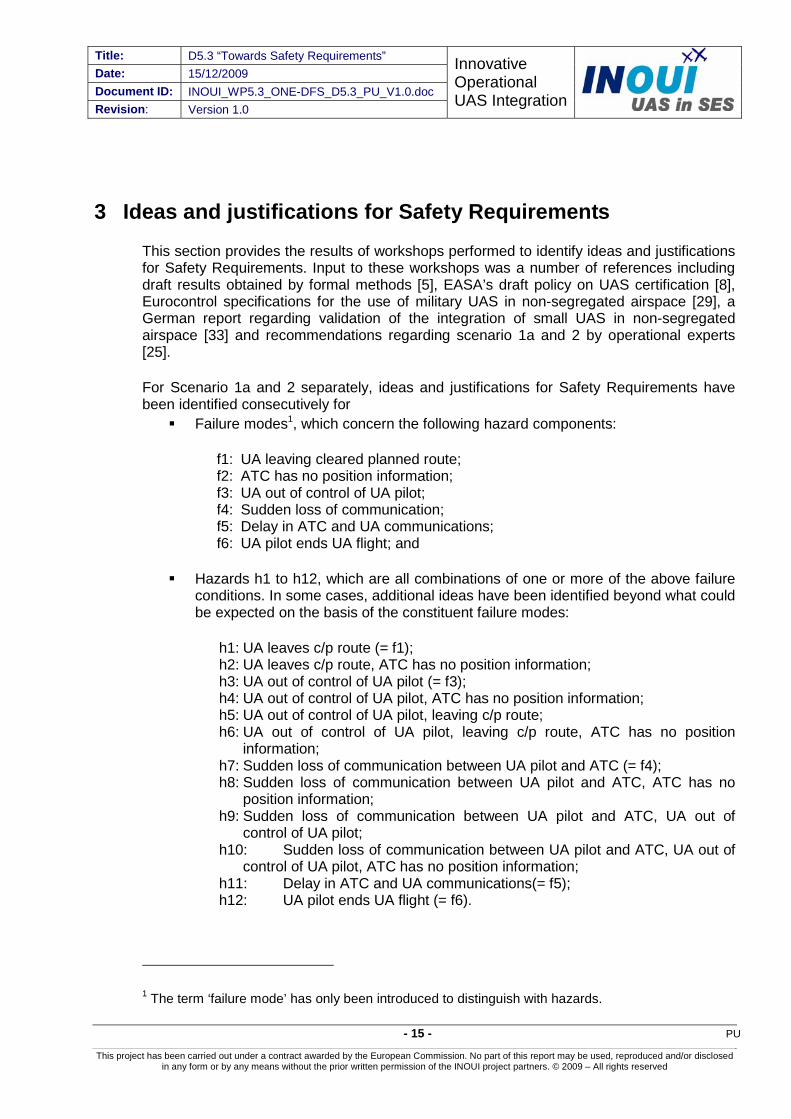
Failure modes1, which concern the following hazard components:
f1: UA leaving cleared planned route; f2: ATC has no position information; f3: UA out of control of UA pilot; f4: Sudden loss of communication; f5: Delay in ATC and UA communications; f6: UA pilot ends UA flight; and
Hazards h1 to h12, which are all combinations of one or more of the above failure conditions. In some cases, additional ideas have been identified beyond what could be expected on the basis of the constituent failure modes:
h1: UA leaves c/p route (= f1); h2: UA leaves c/p route, ATC has no position information; h3: UA out of control of UA pilot (= f3); h4: UA out of control of UA pilot, ATC has no position information; h5: UA out of control of UA pilot, leaving c/p route; h6: UA out of control of UA pilot, leaving c/p route, ATC has no position
information; h7: Sudden loss of communication between UA pilot and ATC (= f4); h8: Sudden loss of communication between UA pilot and ATC, ATC has no
position information; h9: Sudden loss of communication between UA pilot and ATC, UA out of
control of UA pilot; h10: Sudden loss of communication between UA pilot and ATC, UA out of
control of UA pilot, ATC has no position information; h11: Delay in ATC and UA communications(= f5); h12: UA pilot ends UA flight (= f6).
1 The term ‘failure mode’ has only been introduced to distinguish with hazards.

Title: D5.3 “Towards Safety Requirements” Date: 15/12/2009
Document ID: INOUI_WP5.3_ONE-DFS_D5.3_PU_V1.0.doc
Innovative Operational UAS Integration
Revision: Version 1.0
PU - 16 -
This project has been carried out under a contract awarded by the European Commission. No part of this report may be used, reproduced and/or disclosed in any form or by any means without the prior written permission of the INOUI project partners. © 2009 – All rights reserved
In addition ‘out-of-the-box’ ideas for improving the scenarios have been obtained. These are not directly associated to a failure mode or hazard, or may fundamentally change the scenarios.
The analysis for Scenario 2 is less detailed than for Scenario 1a.
3.1 Scenario 1a – High performance UAS in high density airspace 3.1.1 Ideas and justifications for Safety Requirements for Failure modes
Id Failure mode/Hazard Safety Objective (Interpretation how difficult to achieve) f1=h1 UA leaving cleared/planned
route. f1=h1 shall not occur more often than once in 10 years (very difficult)
Id Idea for Safety Requirement Justification 1-f1-a The UAS shall be able to
detect any deviation of the unmanned aircraft from the cleared/planned route and provide the UA pilot with an appropriate warning.
This capability will be provided by an embedded system able to detect any deviation (vertical and lateral) between cleared/planned route and actual position. This will help the UA pilot to get aware of any deviation at an early stage.
1-f1-b Any unmanned aircraft shall have a dedicated means for detecting deviations (both lateral and vertical) between cleared/ planned route and actual position.
To avoid excessive complexity, such system could be equipped with a differential GPS system.
A differential GPS system is dedicated equipment giving a highly precise location (in 4D). Unfortunately a differential GPS is only available in the vicinity of airport and is very expensive.
1-f1-c The system shall be able to detect the deviation in real time to facilitate the resolution of any potential conflict that arises due to the deviation.
According to the ATCOs, the vertical deviations introduce a much more severe risk, so it is important to have the capability to detect this type of deviations in real time.
Id Reconsideration of Safety Objective f1=h1 Systems to measure accurately the unmanned aircraft’s position and detect deviations
between flight plan/clearance at first sight seem standard equipment. This seems insufficient to achieve the very strict safety objective. Possibly, independent additional systems can bring significant improvements, but it must be noted that not all deviations have technical origins. For instance misunderstandings by the UA pilot or situations where the pilot has no control over the UA may cause situations in which the systems think the UA is flying precisely according to plan/clearance whereas, in fact, ATC has another plan/clearance or does not even know the intentions of the UA.
Id Failure mode/Hazard Safety Objective (Interpretation how difficult to achieve) f2 ATC has no position
information. n/a
Id Idea for Safety Requirement Justification 1-f2-a The UA pilot is responsible to
provide ATC with position information derived from the unmanned aircraft systems
As the UA pilot will continue to receive the unmanned aircraft position on the control station, he will be in a good position to transmit periodic position reports to the ATC.

Title: D5.3 “Towards Safety Requirements” Date: 15/12/2009 Document ID: INOUI_WP5.3_ONE-DFS_D5.3_PU_V1.0.doc Revision: Version 1.0
Innovative Operational UAS Integration
- 17 - PU
This project has been carried out under a contract awarded by the European Commission. No part of this report may be used, reproduced and/or disclosed in any form or by any means without the prior written permission of the INOUI project partners. © 2009 – All rights reserved
when requested. 1-f2-b The unmanned aircraft will be
fitted with dedicated suitable navigation systems according to the MMEL.
This will assure that the pilot always receive accurate information related to the unmanned aircraft position.
Id Reconsideration of Safety Objective f2 Position reports for UAS for situation in which the transponder does not function are
analogous to such reports for manned aircraft. Reliable navigation and communication between Control Station and Unmanned Aircraft are however crucial to make position reporting as effective as for manned aircraft. The identified ideas seem insufficient as lack of position information for ATC is judged more safety critical for unmanned than for manned aircraft.
Id Failure mode/Hazard Safety Objective (Interpretation how difficult to achieve) f3=h3 UA out of control of UA pilot. f3=h3 shall not occur more often than once every 5 days
(easy) Id Idea for Safety Requirement Justification 1-f3-a The UAS should provide the
UA pilot with continuous information related to the status of the UA control link.
To be successful in implementing a mitigation measure, it is important to have very early detection of a loss of control event.
1-f3-b The UAS should be able to detect a loss of control event (after a predetermined number of seconds) and automatically revert to an automatic control mode.
To be successful in implementing a mitigation measure, it is important to have very early detection of a loss of control event and to allow the unmanned aircraft to autonomously revert to an automatic control mode flying a pre-programmed flight path previously coordinated with ATC.
1-f3-c If the UAS is able to recover from a loss of link it shall inform the UA pilot who is offered to take control of it again.
In the case of a temporal outage of the control link, the UAS must be able to revert to manual control mode once the control link is re-established, as far as the UA pilot agrees.
1-f3-d Adding a new special transponder code to inform the ATC of this type of failure.
This will allow ATC to know about the loss of link and take the required actions.
1-f3-e The special transponder code must be set automatically by the unmanned aircraft.
As there is a control link failure, the UA pilot is not able to set up the code, so that must be done automatically by the unmanned aircraft.
Id Reconsideration of Safety Objective f3=h3 Perhaps surprisingly, the loss of control of the UA by the UA pilot has not been assessed
to be a very safety critical hazard. It must however be noted that for this classification, it is presumed that the UA accurately follows its cleared/planned route, which becomes much more challenging when control has been lost.
Deviations from the cleared/planned route in case of loss of command and control link are dealt with in h5.
Title: D5.3 “Towards Safety Requirements” Date: 15/12/2009
Document ID: INOUI_WP5.3_ONE-DFS_D5.3_PU_V1.0.doc
Innovative Operational UAS Integration
Revision: Version 1.0
PU - 18 -
This project has been carried out under a contract awarded by the European Commission. No part of this report may be used, reproduced and/or disclosed in any form or by any means without the prior written permission of the INOUI project partners. © 2009 – All rights reserved
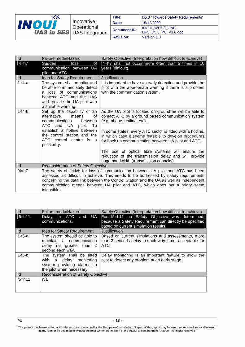
Id Failure mode/Hazard Safety Objective (Interpretation how difficult to achieve) f4=h7 Sudden loss of
communication between UA pilot and ATC.
f4=h7 shall not occur more often than 5 times in 10 years (difficult).
Id Idea for Safety Requirement Justification 1-f4-a The system shall monitor and
be able to immediately detect a loss of communications between ATC and the UAS and provide the UA pilot with a suitable warning.
It is important to have an early detection and provide the pilot with the appropriate warning if there is a problem with the communication system.
1-f4-b Set up the capability of an alternative means of communications between ATC and UA pilot. To establish a hotline between the control station and the ATC control centre is a possibility.
As the UA pilot is located on ground he will be able to contact ATC by a ground based communication system (e.g. phone, hotline, etc).
In some states, every ATC sector is fitted with a hotline, in which case it seems feasible to develop procedures for back up communication between UA pilot and ATC.
The use of optical fibre systems will ensure the reduction of the transmission delay and will provide huge bandwidth (transmission capacity).
Id Reconsideration of Safety Objective f4=h7 The safety objective for loss of communication between UA pilot and ATC has been
assessed as difficult to achieve. This needs to be addressed by safety requirements concerning the data link between the Control Station and the UA as well as independent communication means between UA pilot and ATC, which does not a priory seem infeasible.
Id Failure mode/Hazard Safety Objective (Interpretation how difficult to achieve) f5=h11 Delay in ATC and UA
communications. For f5=h11 no Safety Objective was determined, because a Safety Requirement can directly be specified based on current simulation results.
Id Idea for Safety Requirement Justification 1-f5-a The system should be able to
maintain a communication delay no greater than 2 second each way.
Based on current simulations and assessments, more than 2 seconds delay in each way is not acceptable for ATC.
1-f5-b The system shall be fitted with a delay monitoring system providing alarms to the pilot when necessary.
Delay monitoring is an important feature to allow the pilot to detect any problem at an early stage.
Id Reconsideration of Safety Objective f5=h11 n/a
Title: D5.3 “Towards Safety Requirements” Date: 15/12/2009 Document ID: INOUI_WP5.3_ONE-DFS_D5.3_PU_V1.0.doc Revision: Version 1.0
Innovative Operational UAS Integration
- 19 - PU
This project has been carried out under a contract awarded by the European Commission. No part of this report may be used, reproduced and/or disclosed in any form or by any means without the prior written permission of the INOUI project partners. © 2009 – All rights reserved
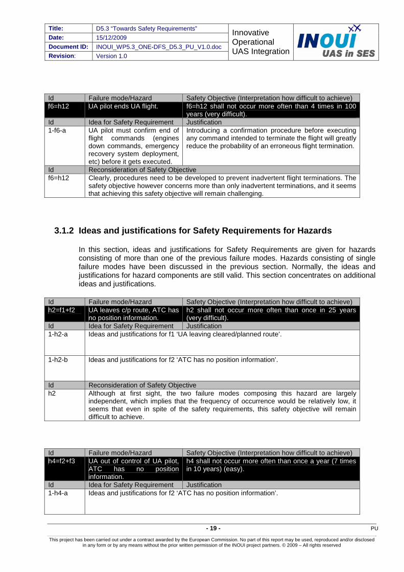
Id Failure mode/Hazard Safety Objective (Interpretation how difficult to achieve) f6=h12 UA pilot ends UA flight. f6=h12 shall not occur more often than 4 times in 100
years (very difficult). Id Idea for Safety Requirement Justification 1-f6-a UA pilot must confirm end of
flight commands (engines down commands, emergency recovery system deployment, etc) before it gets executed.
Introducing a confirmation procedure before executing any command intended to terminate the flight will greatly reduce the probability of an erroneous flight termination.
Id Reconsideration of Safety Objective f6=h12 Clearly, procedures need to be developed to prevent inadvertent flight terminations. The
safety objective however concerns more than only inadvertent terminations, and it seems that achieving this safety objective will remain challenging.
3.1.2 Ideas and justifications for Safety Requirements for Hazards
In this section, ideas and justifications for Safety Requirements are given for hazards consisting of more than one of the previous failure modes. Hazards consisting of single failure modes have been discussed in the previous section. Normally, the ideas and justifications for hazard components are still valid. This section concentrates on additional ideas and justifications.
Id Failure mode/Hazard Safety Objective (Interpretation how difficult to achieve) h2=f1+f2 UA leaves c/p route, ATC has
no position information. h2 shall not occur more often than once in 25 years (very difficult).
Id Idea for Safety Requirement Justification 1-h2-a Ideas and justifications for f1 ‘UA leaving cleared/planned route’.
1-h2-b Ideas and justifications for f2 ‘ATC has no position information’.
Id Reconsideration of Safety Objective h2 Although at first sight, the two failure modes composing this hazard are largely
independent, which implies that the frequency of occurrence would be relatively low, it seems that even in spite of the safety requirements, this safety objective will remain difficult to achieve.
Id Failure mode/Hazard Safety Objective (Interpretation how difficult to achieve) h4=f2+f3 UA out of control of UA pilot,
ATC has no position information.
h4 shall not occur more often than once a year (7 times in 10 years) (easy).
Id Idea for Safety Requirement Justification 1-h4-a Ideas and justifications for f2 ‘ATC has no position information’.

Title: D5.3 “Towards Safety Requirements” Date: 15/12/2009
Document ID: INOUI_WP5.3_ONE-DFS_D5.3_PU_V1.0.doc
Innovative Operational UAS Integration
Revision: Version 1.0
PU - 20 -
This project has been carried out under a contract awarded by the European Commission. No part of this report may be used, reproduced and/or disclosed in any form or by any means without the prior written permission of the INOUI project partners. © 2009 – All rights reserved
1-h4-b Ideas and justifications for f3 ‘UA out of control of UA pilot’.
1-h4-c In the case of only uplink not
working, the UA pilot will provide ATC with position reports on the unmanned aircraft path.
It can be assumed that the UA pilot continues to receive information from the UA onboard systems, so he will be able to report position to ATC.
1-h4-d If both uplink and downlink fails, the pilot must call ATC to provide them with the pre-programmed route that the UAS is supposed to fly.
In the case of a total failure of the command and control data link, the UA pilot needs to know which is the pre-programmed flight path and will inform ATC who will clear the route and its neighbourhood.
1-h4-e ATC should know about the pre-programmed routes before the flight.
As there may be multiple pre-programmed routes and the one actually selected may depend on different parameters (flight phase, unmanned aircraft status, etc), ATC must be informed of the possibilities and selection rules in a strategic phase.
Id Reconsideration of Safety Objective h4 As for hazard h2, the two failure modes composing this hazard are largely independent,
which implies that the frequency of occurrence would be relatively low, which explains why this safety objective would be relatively easy to achieve.
It must however be noted that for this classification, it is presumed that the UA accurately follows its cleared/planned route, which is challenging to arrange in loss of control situations. As there may be more than procedure for loss of control situations exists, there is potential for misunderstandings and the UA pilot must then coordinate the precise procedure that will be followed with ATC. The case where the UA leaves the cleared/planned route is dealt with in h5.
It has been implicitly assumed that command and control uses another link as communication. This assumption is crucial for the Safety Requirements: in case communication is lost as well, there will be no means for position reporting.
Id Failure mode/Hazard Safety Objective (Interpretation how difficult to achieve) h5=f1+f3 UA out of control of UA pilot,
leaving c/p route. h5 shall not occur more often than 6 times in 100 years (very difficult).
Id Idea for Safety Requirement Justification 1-h5-a Ideas and justifications for f1 ‘UA leaving cleared/planned route’.
1-h5-b Ideas and justifications for f3 ‘UA out of control of UA pilot’.
1-h5-c Pilot must inform ATC about
the pre-programmed (loss of control) route of the unmanned aircraft.
ATC must know the procedure for the unmanned aircraft in the case of a control loss.
Title: D5.3 “Towards Safety Requirements” Date: 15/12/2009 Document ID: INOUI_WP5.3_ONE-DFS_D5.3_PU_V1.0.doc Revision: Version 1.0
Innovative Operational UAS Integration
- 21 - PU
This project has been carried out under a contract awarded by the European Commission. No part of this report may be used, reproduced and/or disclosed in any form or by any means without the prior written permission of the INOUI project partners. © 2009 – All rights reserved
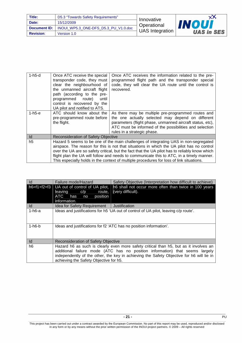
1-h5-d Once ATC receive the special transponder code, they must clear the neighbourhood of the unmanned aircraft flight path (according to the pre-programmed route) until control is recovered by the UA pilot and notified to ATS.
Once ATC receives the information related to the pre-programmed flight path and the transponder special code, they will clear the UA route until the control is recovered.
1-h5-e ATC should know about the pre-programmed route before the flight.
As there may be multiple pre-programmed routes and the one actually selected may depend on different parameters (flight phase, unmanned aircraft status, etc), ATC must be informed of the possibilities and selection rules in a strategic phase.
Id Reconsideration of Safety Objective h5 Hazard 5 seems to be one of the main challenges of integrating UAS in non-segregated
airspace. The reason for this is not that situations in which the UA pilot has no control over the UA are so safety critical, but the fact that the UA pilot has to reliably know which flight plan the UA will follow and needs to communicate this to ATC, in a timely manner. This especially holds in the context of multiple procedures for loss of link situations.
Id Failure mode/Hazard Safety Objective (Interpretation how difficult to achieve) h6=f1+f2+f3 UA out of control of UA pilot,
leaving c/p route,ATC has no position information.
h6 shall not occur more often than twice in 100 years (very difficult).
Id Idea for Safety Requirement Justification 1-h6-a Ideas and justifications for h5 ‘UA out of control of UA pilot, leaving c/p route’.
1-h6-b Ideas and justifications for f2 ‘ATC has no position information’.
Id Reconsideration of Safety Objective h6 Hazard h6 as such is clearly even more safety critical than h5, but as it involves an
additional failure mode (ATC has no position information) that seems largely independently of the other, the key in achieving the Safety Objective for h6 will lie in achieving the Safety Objective for h5.
Title: D5.3 “Towards Safety Requirements” Date: 15/12/2009
Document ID: INOUI_WP5.3_ONE-DFS_D5.3_PU_V1.0.doc
Innovative Operational UAS Integration
Revision: Version 1.0
PU - 22 -
This project has been carried out under a contract awarded by the European Commission. No part of this report may be used, reproduced and/or disclosed in any form or by any means without the prior written permission of the INOUI project partners. © 2009 – All rights reserved
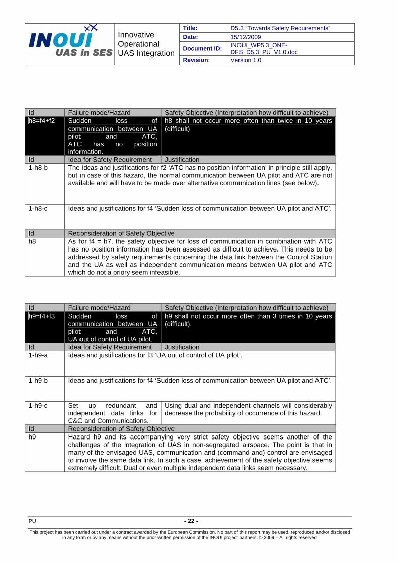
Id Failure mode/Hazard Safety Objective (Interpretation how difficult to achieve) h8=f4+f2 Sudden loss of
communication between UA pilot and ATC, ATC has no position information.
h8 shall not occur more often than twice in 10 years (difficult)
Id Idea for Safety Requirement Justification 1-h8-b The ideas and justifications for f2 ‘ATC has no position information’ in principle still apply,
but in case of this hazard, the normal communication between UA pilot and ATC are not available and will have to be made over alternative communication lines (see below).
1-h8-c Ideas and justifications for f4 ‘Sudden loss of communication between UA pilot and ATC’.
Id Reconsideration of Safety Objective h8 As for f4 = h7, the safety objective for loss of communication in combination with ATC
has no position information has been assessed as difficult to achieve. This needs to be addressed by safety requirements concerning the data link between the Control Station and the UA as well as independent communication means between UA pilot and ATC which do not a priory seem infeasible.
Id Failure mode/Hazard Safety Objective (Interpretation how difficult to achieve) h9=f4+f3 Sudden loss of
communication between UA pilot and ATC, UA out of control of UA pilot.
h9 shall not occur more often than 3 times in 10 years (difficult).
Id Idea for Safety Requirement Justification 1-h9-a Ideas and justifications for f3 ‘UA out of control of UA pilot’.
1-h9-b Ideas and justifications for f4 ‘Sudden loss of communication between UA pilot and ATC’.
1-h9-c Set up redundant and
independent data links for C&C and Communications.
Using dual and independent channels will considerably decrease the probability of occurrence of this hazard.
Id Reconsideration of Safety Objective h9 Hazard h9 and its accompanying very strict safety objective seems another of the
challenges of the integration of UAS in non-segregated airspace. The point is that in many of the envisaged UAS, communication and (command and) control are envisaged to involve the same data link. In such a case, achievement of the safety objective seems extremely difficult. Dual or even multiple independent data links seem necessary.

Title: D5.3 “Towards Safety Requirements” Date: 15/12/2009 Document ID: INOUI_WP5.3_ONE-DFS_D5.3_PU_V1.0.doc Revision: Version 1.0
Innovative Operational UAS Integration
- 23 - PU
This project has been carried out under a contract awarded by the European Commission. No part of this report may be used, reproduced and/or disclosed in any form or by any means without the prior written permission of the INOUI project partners. © 2009 – All rights reserved
Id Failure mode/Hazard Safety Objective (Interpretation how difficult to achieve) h10=f4+f3+f2
Sudden loss of communication between UA pilot and ATC,UA out of control of UA pilot,ATC has no position information.
h10 shall not occur more often than once in 10 years (difficult).
Id Idea for Safety Requirement Justification 1-h10-a The ideas and justifications for f2 ‘ATC has no position information’ in principle still apply,
but in case of this hazard, the normal communication between UA pilot and ATC is not available and will have to be made over alternative communication lines (see below).
1-h10-b Ideas and justifications for h9 ‘Sudden loss of communication between UA pilot and
ATC, UA out of control of UA pilot.’
Id Reconsideration of Safety Objective h10 Adding to h9 the additional failure mode of ATC has no position information of course
makes the hazard more safety critical. As a cause, the latter failure mode is however to a high degree independent of the other, therefore achievement of the corresponding Safety Objective will depend on achieving the corresponding Safety Objective for hazard h9.
3.1.3 Out-of-the-box Ideas and justifications for Safety Requirements
Id Proposal for Safety Requirement
Explanation/motivation for Safety Requirement including reference if applicable
1-1 The UA pilot should be provided with a traffic display providing situation awareness regarding near traffic.
This system will enhance the situational awareness of the UA pilot including the case of an in-flight conflict.
Such a display would in all cases where the UA pilot is normally in command and control of the UA provide significant improvements to the ability to prevent collisions, provided the UA pilot is appropriately trained.
Hence this out-of-the-box safety requirement would facilitate the achievement of safety objectives for various hazards.

Title: D5.3 “Towards Safety Requirements” Date: 15/12/2009
Document ID: INOUI_WP5.3_ONE-DFS_D5.3_PU_V1.0.doc
Innovative Operational UAS Integration
Revision: Version 1.0
PU - 24 -
This project has been carried out under a contract awarded by the European Commission. No part of this report may be used, reproduced and/or disclosed in any form or by any means without the prior written permission of the INOUI project partners. © 2009 – All rights reserved
1-2 TCAS system shall be reconfigured to cope with the delay in pilot responses. Possibly automatic RA could be set up.
Current TCAS algorithms were designed taking into account manned aircraft performances. Therefore reaction times and distances are calculated for those performances. Due to the poor performances associated to some of the existing UAS, current TCAS algorithms are not enough to solve problems where those UAS are involved.
Therefore will be required to define a “next generation” TCAS that takes these issues into account.
Is important to highlight that current TCAS version has fixed reaction times by regulations.
1-3 Pay due attention to the control station design regarding ergonomics and human factors.
Identification of flight critical commands and design its execution from a fail safe perspective (including human induced errors).

Title: D5.3 “Towards Safety Requirements” Date: 15/12/2009 Document ID: INOUI_WP5.3_ONE-DFS_D5.3_PU_V1.0.doc Revision: Version 1.0
Innovative Operational UAS Integration
- 25 - PU
This project has been carried out under a contract awarded by the European Commission. No part of this report may be used, reproduced and/or disclosed in any form or by any means without the prior written permission of the INOUI project partners. © 2009 – All rights reserved
3.2 Scenario 2 – Low performance UAS in low density airspace
3.2.1 Ideas and justifications for Safety Requirements for Failure modes
Id Failure mode/Hazard Safety Objective (Interpretation how difficult to achieve) f1=h1 UA leaving cleared/planned
route f1=h1 shall not occur more often than once in 10 years (very difficult)
Id Idea for Safety Requirement Justification 2-f1-a There shall exist a monitoring
system embedded in the CS that is able to warn the pilot in case a deviation from the cleared/planned route occurs.
Control stations are equipped with sub systems, especially monitors, which show the pilot the trajectory being flown by the UA so that he/she is aware of the current position of the UAS.
A warning system, either visual, aural or both, shall be incorporated to these sub systems warning the pilot when a deviation of the planned position of the UA takes place.
2-f1-b The UA Pilot shall be able to react to the warnings in case the UA leaves the cleared/planned route.
A major purpose of FMS is to help the flight crew with flight planning. The flight crew can enter the flight plan in the FMS. This flight plan includes the intended lateral and vertical trajectory. When all of the necessary data is entered, the FMS computes and displays the speed, altitude, time, and fuel predictions that are associated with the flight plan. Furthermore, the FMS can command the autopilot to execute the flight plan. The flight crew can change the flight plan at any time. If the change is made to the lateral flight plan, the change is called a lateral revision. If the change is made to the vertical flight plan, the change is called a vertical revision.
UAS are also equipped with FMS which can perform such functions. Thus the UA pilot is able to modify flight plan in case any change needs to be implemented takes place (e.g. a deviation from the cleared/planned route).
2-f1-c The UA shall have an automatic mode for detecting and going back to the cleared/planned route.
The above requirements imply that the pilot is in command and control of the UA. However due to the fact that a high degree of automation is expected for UAS, they shall be equipped with automatic systems for detecting and going back to the cleared/planned route. Such functions are currently being developed. An example of such system is the Flight Reconfiguration Function (FRF) which enables the modification of the flight plan automatically in the FMS and executes it without any command and control from ground.
2-f1-d Improve perceptibility of small UA for other VFR traffic e.g. by strobe lights.
The safety of operations in the mixed environment of Scenario 2 depends to a considerable degree on the effective “see and avoid” by the VFR aircraft not in communication with ATC.

Title: D5.3 “Towards Safety Requirements” Date: 15/12/2009
Document ID: INOUI_WP5.3_ONE-DFS_D5.3_PU_V1.0.doc
Innovative Operational UAS Integration
Revision: Version 1.0
PU - 26 -
This project has been carried out under a contract awarded by the European Commission. No part of this report may be used, reproduced and/or disclosed in any form or by any means without the prior written permission of the INOUI project partners. © 2009 – All rights reserved
Id Reconsideration of Safety Objective f1 Equipment on the CS and the UA able to detect, indicate and/or correct deviations will
contribute to achieving the Safety Objective. Nevertheless, not all deviations will be caught by such equipment as e.g. misunderstandings between ATC and UA pilot may be underlying them.
Id Failure mode/Hazard Safety Objective (Interpretation how difficult to achieve) f2 ATC has no position
information n/a
Id Idea for Safety Requirement Justification 2-f2-a ATC shall inform the UA Pilot
when ATC has no position information.
Currently controllers ask information of the pilots when they are not sure about the information they are receiving on the radar screen. Therefore the same request shall be asked the UA pilot when ATC has no position information or ATC believes it is wrong.
2-f2-b The UA Pilot shall inform ATC about the UA position when required by ATC.
Two way communications is an issue already addressed in ICAO Doc 4444 [36]. Therefore continuous two way communication informing about the position and other UA aspects shall be performed as well as for manned aviation.
2-f2-c The UA Pilot should have traffic information on the CS.
A pilot’s description of Situational Awareness, as defined in [35] would be “knowing what is going on so you can figure out what to do”. In manned aviation, pilots can “look through the window” to look for surrounding traffic, as well as listen to the information provided by controllers when there is traffic around. In recent times CDTI is a supporting tool for pilots, which is currently being developed. A similar device on the CS has also been proposed in INOUI D2.2 to enhance UA pilot’s traffic picture [40].
Id Reconsideration of Safety Objective
f2 The first two ideas for Safety Requirements are the same as for manned aircraft. The communication required between UA and Control Station however makes this failure mode more safety critical, even if it would to some extent be mitigated by the availability of traffic information to the UA pilot.
Id Failure mode/Hazard Safety Objective (Interpretation how difficult to achieve) f3=h3 UA out of control of UA pilot f3=h3 shall not occur more often than 4 times in 10
years (very difficult) Id Idea for Safety Requirement Justification
Title: D5.3 “Towards Safety Requirements” Date: 15/12/2009 Document ID: INOUI_WP5.3_ONE-DFS_D5.3_PU_V1.0.doc Revision: Version 1.0
Innovative Operational UAS Integration
- 27 - PU
This project has been carried out under a contract awarded by the European Commission. No part of this report may be used, reproduced and/or disclosed in any form or by any means without the prior written permission of the INOUI project partners. © 2009 – All rights reserved
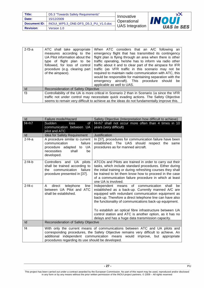
2-f3-a ATC shall take appropriate measures according to the UA Pilot information about the type of flight plan to be followed, for loss of control procedure (e.g. clearing part of the airspace).
When ATC considers that an A/C following an emergency flight that has transmitted its contingency flight plan is flying through an area when there is other traffic operating, he/she has to inform via radio other traffic about it and to clear part of the airspace for IFR traffic (as VFR traffic in this scenario may not be required to maintain radio communication with ATC, this would be responsible for maintaining separation with the emergency aircraft). This procedure should be applicable as well to UAS.
Id Reconsideration of Safety Objective f3 Controllability of the UA is more critical in Scenario 2 than in Scenario 1a since the VFR
traffic not under control may necessitate quick evading actions. The Safety Objective seems to remain very difficult to achieve as the ideas do not fundamentally improve this.
Id Failure mode/Hazard Safety Objective (Interpretation how difficult to achieve) f4=h7 Sudden loss of
communication between UA pilot and ATC
f4=h7 shall not occur more often than 4 times in 10 years (very difficult)
Id Idea for Safety Requirement Justification 2-f4-a A procedure similar to current
communication failure procedure adapted to UA necessities shall be developed.
In [37], procedures for communication failure have been established. The UAS should respect the same procedures as for manned aircraft.
2-f4-b Controllers and UA pilots shall be trained according to the communication failure procedure presented in [37].
ATCOs and Pilots are trained in order to carry out their tasks, which include standard procedures. Either during the initial training or during refreshing courses they shall be trained to let them know how to proceed in the case of a communication failure procedure in which at least one UA is involved.
2-f4-c A direct telephone line between UA Pilot and ATC shall be established.
Independent means of communication shall be established as a back-up. Currently manned A/C are equipped with redundant communication equipment as back-up. Therefore a direct telephone line can have also the functionality of communications back-up equipment.
To establish an optical fibre infrastructure between UA control station and ATC is another option, as it has no delays and has a huge data transmission capacity.
Id Reconsideration of Safety Objective
f4 With only the current means of communications between ATC and UA pilots and corresponding procedures, the Safety Objective remains very difficult to achieve. An additional independent communication means would improve, but appropriate procedures regarding its use should be developed.

Title: D5.3 “Towards Safety Requirements” Date: 15/12/2009
Document ID: INOUI_WP5.3_ONE-DFS_D5.3_PU_V1.0.doc
Innovative Operational UAS Integration
Revision: Version 1.0
PU - 28 -
This project has been carried out under a contract awarded by the European Commission. No part of this report may be used, reproduced and/or disclosed in any form or by any means without the prior written permission of the INOUI project partners. © 2009 – All rights reserved
Id Failure mode/Hazard Safety Objective (Interpretation how difficult to achieve) f5=h11 Delay in ATC and UA
communications
For f5=h11 no Safety Objective was determined, because a Safety Requirement can directly be specified based on current simulation results
Id Idea for Safety Requirement Justification 2-f5-a Clearances and instructions
from ATC to UA Pilot (and other traffic) shall be issued taking into account maximum delay accepted.
It has been demonstrated through different projects such as in [33] and in [41] that a delay of 2 seconds is workable for the controller but a delay of 4 seconds is not tolerable. Therefore clearances and instructions shall be issued considering this maximum delay.
2-f5-b A direct telephone line between UA Pilot and ATC shall be established.
Independent means of communication shall be established as a back-up. Currently manned A/C are equipped with redundant communication equipment as back-up. Therefore a direct telephone line can have also the functionality of communications back-up equipment.
To establish an optical fibre infrastructure between UA control station and ATC is another option, as it has no delays and has a huge data transmission capacity.
Id Failure mode/Hazard Safety Objective (Interpretation how difficult to achieve) f6=h12 UA pilot ends UA flight f6=h12 shall not occur more often than 4 times in 100
years (very difficult) Id Idea for Safety Requirement Justification 2-f6-a It shall be developed
procedures regarding termination modes (e.g. engine shutdown, mission cancellation, controlled crash, etc.)
A list of termination modes (either through UA flight crew command or through a pre-programmed course of action) has to be concreted by UAS manufacturers when applying for certification of the platform, according to [8], Section 7.1. For instance a mission cancellation shall include a pre-programmed trajectory.
2-f6-b The UA Pilot and the ATC shall be trained on the procedures regarding termination modes developed
ATCOs and Pilots are trained in order to carry out their tasks, which include standard procedures. Either during the initial training or during refreshing courses they should be trained to let them know how to proceed in the case of a communication failure procedure in which at least one UA is involved.
2-f6-c If the UA Pilot intends to end the UA flight, he/she shall inform ATC and provide information about the situation.
Communication about any abnormal behaviour of the aircraft or the pilot shall be communicated to ATCOs as well as in manned aviation.

Title: D5.3 “Towards Safety Requirements” Date: 15/12/2009 Document ID: INOUI_WP5.3_ONE-DFS_D5.3_PU_V1.0.doc Revision: Version 1.0
Innovative Operational UAS Integration
- 29 - PU
This project has been carried out under a contract awarded by the European Commission. No part of this report may be used, reproduced and/or disclosed in any form or by any means without the prior written permission of the INOUI project partners. © 2009 – All rights reserved
2-f6-d If the UA flight shall to be ended, the UA shall follow a pre-programmed trajectory
Extracted from [8]:
While there is no mandatory airworthiness requirement to fit or configure systems to provide an emergency recovery capability, an applicant may propose such a capability in order to mitigate the effects of certain failure conditions (e.g. total loss of command and control link). Such a capability will normally consist of either:
a) A flight termination system; (e.g. a whole aircraft recovery parachute) which aims to immediately end the flight and to reduce the kinetic energy at impact, but does not necessarily ensure the crash / impact point location, or
b) Emergency recovery procedures such as functions that could be implemented through UAS flight crew command or through an automatic pre-programmed course of action, that are intended to navigate the unmanned aircraft to a pre-selected emergency site and then to make a safe landing or terminate the flight.
2-f6-e ATC shall know the intentions (landing place, contingency flight plan, etc.) of the UA, when the UA pilot ends the flight.
When the UA pilot ends the UA flight, this shall be done, according to the possible termination modes defined for such an UA. As soon as the termination mode is known, the UA pilot shall inform ATC to let him/her take appropriate measures.
3.2.2 Ideas and justifications for Safety Requirements for Hazards
Id Failure mode/Hazard Safety Objective (Interpretation how difficult to achieve) h2=f1+f2 UA leaves c/p route, ATC has
no position information h2 shall not occur more often than twice in 10 years (difficult)
Id Idea for Safety Requirement Justification The ideas for safety requirements applicable to Failure Modes 1 and 2 are still applicable
to this hazard.
Id Failure mode/Hazard Safety Objective (Interpretation how difficult to achieve) h4=f2+f3 UA out of control of UA pilot,
ATC has no position information
h4 shall not occur more often than twice in 10 years (very difficult)
Id Idea for Safety Requirement Justification The ideas for safety requirements applicable to Failure Modes 2 and 3 are still applicable
Title: D5.3 “Towards Safety Requirements” Date: 15/12/2009
Document ID: INOUI_WP5.3_ONE-DFS_D5.3_PU_V1.0.doc
Innovative Operational UAS Integration
Revision: Version 1.0
PU - 30 -
This project has been carried out under a contract awarded by the European Commission. No part of this report may be used, reproduced and/or disclosed in any form or by any means without the prior written permission of the INOUI project partners. © 2009 – All rights reserved
to this hazard.
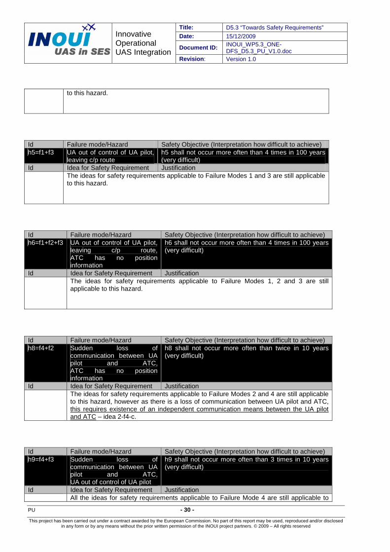
Id Failure mode/Hazard Safety Objective (Interpretation how difficult to achieve) h5=f1+f3 UA out of control of UA pilot,
leaving c/p route h5 shall not occur more often than 4 times in 100 years (very difficult)
Id Idea for Safety Requirement Justification The ideas for safety requirements applicable to Failure Modes 1 and 3 are still applicable
to this hazard.
Id Failure mode/Hazard Safety Objective (Interpretation how difficult to achieve) h6=f1+f2+f3 UA out of control of UA pilot,
leaving c/p route, ATC has no position information
h6 shall not occur more often than 4 times in 100 years (very difficult)
Id Idea for Safety Requirement Justification The ideas for safety requirements applicable to Failure Modes 1, 2 and 3 are still
applicable to this hazard.
Id Failure mode/Hazard Safety Objective (Interpretation how difficult to achieve) h8=f4+f2 Sudden loss of
communication between UA pilot and ATC, ATC has no position information
h8 shall not occur more often than twice in 10 years (very difficult)
Id Idea for Safety Requirement Justification The ideas for safety requirements applicable to Failure Modes 2 and 4 are still applicable
to this hazard, however as there is a loss of communication between UA pilot and ATC, this requires existence of an independent communication means between the UA pilot and ATC – idea 2-f4-c.
Id Failure mode/Hazard Safety Objective (Interpretation how difficult to achieve) h9=f4+f3 Sudden loss of
communication between UA pilot and ATC, UA out of control of UA pilot
h9 shall not occur more often than 3 times in 10 years (very difficult)
Id Idea for Safety Requirement Justification All the ideas for safety requirements applicable to Failure Mode 4 are still applicable to
Title: D5.3 “Towards Safety Requirements” Date: 15/12/2009 Document ID: INOUI_WP5.3_ONE-DFS_D5.3_PU_V1.0.doc Revision: Version 1.0
Innovative Operational UAS Integration
- 31 - PU
This project has been carried out under a contract awarded by the European Commission. No part of this report may be used, reproduced and/or disclosed in any form or by any means without the prior written permission of the INOUI project partners. © 2009 – All rights reserved
this hazard, however as there is a loss of communication between UA pilot and ATC, this requires existence of an independent communication means between the UA pilot and ATC – idea 2-f4-c.
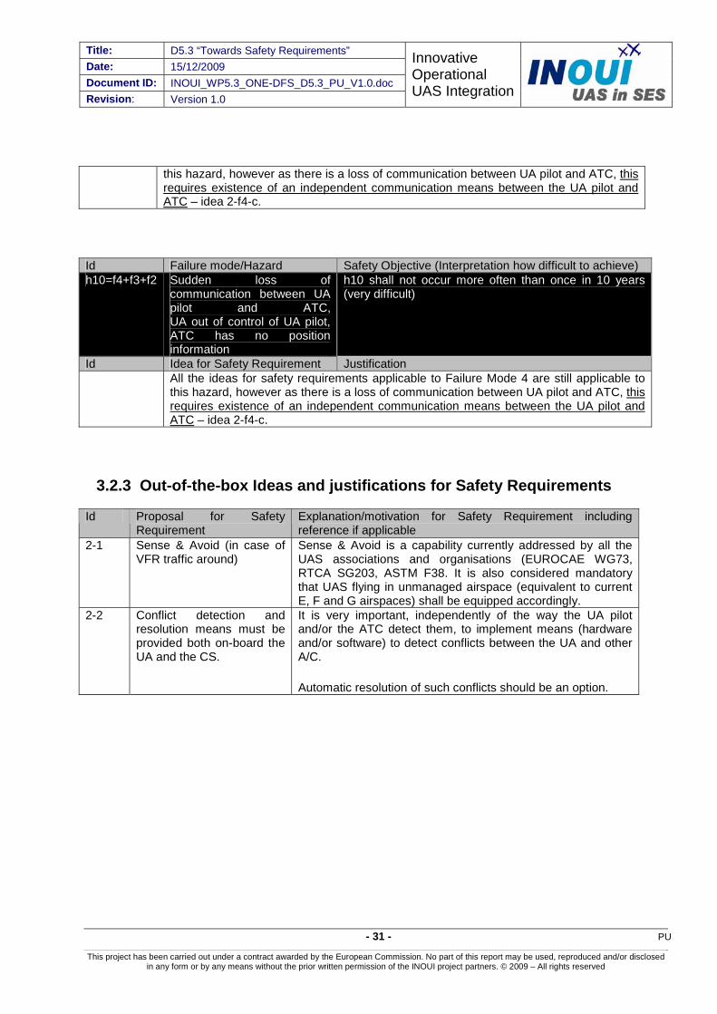
Id Failure mode/Hazard Safety Objective (Interpretation how difficult to achieve) h10=f4+f3+f2 Sudden loss of
communication between UA pilot and ATC,UA out of control of UA pilot,ATC has no position information
h10 shall not occur more often than once in 10 years (very difficult)
Id Idea for Safety Requirement Justification All the ideas for safety requirements applicable to Failure Mode 4 are still applicable to
this hazard, however as there is a loss of communication between UA pilot and ATC, this requires existence of an independent communication means between the UA pilot and ATC – idea 2-f4-c.
3.2.3 Out-of-the-box Ideas and justifications for Safety Requirements
Id Proposal for Safety Requirement
Explanation/motivation for Safety Requirement including reference if applicable
2-1 Sense & Avoid (in case of VFR traffic around)
Sense & Avoid is a capability currently addressed by all the UAS associations and organisations (EUROCAE WG73, RTCA SG203, ASTM F38. It is also considered mandatory that UAS flying in unmanaged airspace (equivalent to current E, F and G airspaces) shall be equipped accordingly.
2-2 Conflict detection and resolution means must be provided both on-board the UA and the CS.
It is very important, independently of the way the UA pilot and/or the ATC detect them, to implement means (hardware and/or software) to detect conflicts between the UA and other A/C.
Automatic resolution of such conflicts should be an option.
Title: D5.3 “Towards Safety Requirements” Date: 15/12/2009
Document ID: INOUI_WP5.3_ONE-DFS_D5.3_PU_V1.0.doc
Innovative Operational UAS Integration
Revision: Version 1.0
PU - 32 -
This project has been carried out under a contract awarded by the European Commission. No part of this report may be used, reproduced and/or disclosed in any form or by any means without the prior written permission of the INOUI project partners. © 2009 – All rights reserved
4 Example of a formal method to obtain Safety Requirements
4.1 Comparing Safety Requirements for Scenarios 1a and 2
The above Safety Requirements for Scenarios 1a and 2 are based on the same set of failures and hazards. What can be inferred from the point of view of corresponding Safety Requirements?
It is quite obvious that on one hand we have Safety Requirements for very large UAS (Cf. Scenario 1a), and on the other hand Safety Requirements for rather small UAS (Cf. Scenario 2). And, independently of the performances of each kind of UAS, more or less the similar Safety Requirements must be met.
How to handle such a paradox if we would like to integrate both heavy and small UAS in the current ATM?
Whereas integration is not too difficult to imagine for large UAS, it does seem very difficult to handle the inherent complexity of integrating small UAS in the current ATM. This means that the Safety Requirements that have been presented above should be complemented by some performance objectives such as the capability for the Safety Requirements to meet financial constraints.
For large UAS, the financial constraints do seem a hurdle. For small UAS, the financial constraints can block their development. A simple but right answer should be to report some of the Safety Requirements for small UAS at the level of the CS. Indeed, the CS has the main advantage of being reusable, and thus able to be made generic enough to encompass some equipment (hardware and software) that can make the integration of small UAS safer and secure.
4.2 Validation of Safety Requirements What has been presented above is a set of ideas and justifications for Safety Requirements derived in workshops with operational and INOUI experts for the scenarios presented in [19].
This starting point for Safety Requirements needs to be further validated. At this moment, there is no guarantee that the Safety Objectives will be met. The next section will introduce some means able to help solving this very important problem. These means are inherited from Computer Science.
4.3 Fixing failures: using formal methods Implementing as far as it is possible Safety Requirements will allow getting systems that could prevent or avoid failure/hazards appearing. Nonetheless when a failure appears we must do something. One idea consists in fixing bugs, i.e. finding out ways to return the system in a state which is safe enough.

Title: D5.3 “Towards Safety Requirements” Date: 15/12/2009 Document ID: INOUI_WP5.3_ONE-DFS_D5.3_PU_V1.0.doc Revision: Version 1.0
Innovative Operational UAS Integration
- 33 - PU
This project has been carried out under a contract awarded by the European Commission. No part of this report may be used, reproduced and/or disclosed in any form or by any means without the prior written permission of the INOUI project partners. © 2009 – All rights reserved
For these means, so called formal methods are provided, which have been inherited from Computer Science [34]. It is not the purpose of INOUI to study or to develop such methods for UAS. Nonetheless we can suggest very briefly what can be done, especially in the context of integrating UAS in the current and future ATM.
Basically the idea, as mentioned above, consists in describing very rigorously the behaviour of a system, here a UAS, and to exhibit a revisited behaviour such that only safe states exist, even when a failure appears. We do not exhibit them here: they can be found in [5].
4.3.1 Fixing failure f1 “UA leaves cleared/planned route”
Assumption: there exist a so-called Conflict Manager both in the UA and its associated CS.
Here is introduced the behaviour of part of the UAS and CS system that is able to react when failure f1 = hazard h1 appears. In both cases (Scenario 1a and Scenario 2) the answer of the embedded system is the same.

Title: D5.3 “Towards Safety Requirements” Date: 15/12/2009
Document ID: INOUI_WP5.3_ONE-DFS_D5.3_PU_V1.0.doc
Innovative Operational UAS Integration
Revision: Version 1.0
PU - 34 -
This project has been carried out under a contract awarded by the European Commission. No part of this report may be used, reproduced and/or disclosed in any form or by any means without the prior written permission of the INOUI project partners. © 2009 – All rights reserved
Figure 1: State machine associated to hazard h1
The meaning of the state machine represented in this diagram is rather simple: when an f1 failure appears, the UAS is asked to move to the state “h1: conflict detection”. Either there is no conflict due to the f1 failure, or there is one. In the former the UA moves to a new state “h1 - no conflict” where it must perform some actions to go back to its cleared/planned route. Otherwise, when there is a conflict due to the f1 failure, the UA moves to the state
Title: D5.3 “Towards Safety Requirements” Date: 15/12/2009 Document ID: INOUI_WP5.3_ONE-DFS_D5.3_PU_V1.0.doc Revision: Version 1.0
Innovative Operational UAS Integration
- 35 - PU
This project has been carried out under a contract awarded by the European Commission. No part of this report may be used, reproduced and/or disclosed in any form or by any means without the prior written permission of the INOUI project partners. © 2009 – All rights reserved
“h1 – conflict” where the UA must subcontract the conflict solving to an internal thread (a sequence of instructions which may execute in parallel with other threads (notion from computer science)) seen as a subcontractor. Of course all the parameters needed for solving the conflict are given to the threads. The UA waits then for the end of the conflict solving and moves afterwards to the state where there is no more conflict, i.e. “h1 – no conflict”.
This diagram does not consider the way the conflict is solved as it is done in a traditional decision tree. Why? In the ONERA methodology we recommend the use of Object Orientation. That means that a system, here the ground system embedded in the UA CS and the UA system must have independent and cooperative threads called objects. These objects can be considered as threads able to react to triggers, and behave independently from each others, except in a few cases where they can communicate and exchange information.
In other words when an f1 failure appears, either there is no conflict, and the reaction of the embedded UA part of the system is limited to set up actions on UA pushing it on its c/p route it left. Otherwise the embedded UA part of the system prepares all the information for creating an independent and new thread/object we have called “conflict”. This object will be in charge of solving the conflict due to the f1 failure.
Consequently the actions performed in orange states of the above figure are actions that met some Safety Requirements, the list being presented above.
4.3.2 Fixing all the failures
There is no need here to introduce all the diagrams showing how the failures identified above are fixed. The interested reader could find more information in [5].
The methodology used in [5] has allowed deriving other Safety Requirements that to some extent encompass the ones presented above. The other ones not derived from Scenarios 1a and 2 are due to the strong assumptions, as for instance there must exist the notion of conflict.
Title: D5.3 “Towards Safety Requirements” Date: 15/12/2009
Document ID: INOUI_WP5.3_ONE-DFS_D5.3_PU_V1.0.doc
Innovative Operational UAS Integration
Revision: Version 1.0
PU - 36 -
This project has been carried out under a contract awarded by the European Commission. No part of this report may be used, reproduced and/or disclosed in any form or by any means without the prior written permission of the INOUI project partners. © 2009 – All rights reserved
5 Summary and Conclusions
The present INOUI deliverable D5.3 has provided ideas and justifications for Safety Requirements with which the scenarios 1a and 2, developed in INOUI D5.1 and analysed in D5.2 can be improved. As such this document provides a further step in the convergence process towards scenarios for safely integrating UAS in non-segregated controlled airspace.
Scenario 1a concerns a UAS with a performance similar to that of present commercial aircraft, climbing/descending through high density controlled airspace comparable to busy sectors or Terminal Manoeuvring Areas (Scenario 1a) to/from its en-route segment. The UAS flies under Instrument Flight Rules and ATC is responsible for separating it from all surrounding traffic. In Scenario 2 a UAS is considered with a performance that is less than common in general aviation. This UAS flies in low density airspace between Minimum Sector Altitude and flight level 100. Although it flies under Instrument Flight Rules in controlled airspace, there may be surrounding traffic under Visual Flight Rules for which ATC is not responsible for separation, which may not be in contact with ATC, but which is assumed to carry a transponder. Apart from TCAS for the high performance UAS, no Sense and Avoid systems are assumed.
The approach to these ideas and justifications for Safety Requirements has been based on two methods:
Expert workshops in which existing literature and operational expertise has been involved to identify per failure mode, hazard or out-of-the-box such ideas and justifications. The results of these workshops are given in Section 3; and
A rigorous method using UML, with which safety requirements are derived from systematic descriptions of scenarios and hazards, involving the results of the expert based method. See Section 4 for an example application.
These two methods have been used in synergy: Preliminary results of the second method have been input to the expert workshops, and the formal method is used to further structure the results of the expert based method.
Some key messages resting upon the expert based method to obtain ideas and justifications for safety requirements for Scenario 1a are the following:
The loss of control of the UA by the UA pilot on itself has not been assessed as a very safety critical hazard. It must however be noted that for this classification, it is somewhat theoretically presumed that the UA accurately follows its cleared/planned route. This however becomes much more challenging when control has been lost, especially when more than one alternative flight plan for loss of control situations exists. The UA pilot must then accurately predict which one has been selected and inform ATC regarding the alternative flight plan that will be flown. This seems one of the challenges of integrating UAS.
The safety objective for loss of communication between UA pilot and ATC has been assessed as difficult to achieve. This needs to be addressed by safety

Title: D5.3 “Towards Safety Requirements” Date: 15/12/2009 Document ID: INOUI_WP5.3_ONE-DFS_D5.3_PU_V1.0.doc Revision: Version 1.0
Innovative Operational UAS Integration
- 37 - PU
This project has been carried out under a contract awarded by the European Commission. No part of this report may be used, reproduced and/or disclosed in any form or by any means without the prior written permission of the INOUI project partners. © 2009 – All rights reserved
requirements concerning the data link between the Control Station and the UA as well as establishing independent communication means between UA pilot and ATC, which does not a priory seem infeasible.
In combination with other failure modes, failure of the UA’s transponder (which results in ATC has no position information) results in significantly more strict Safety Objectives. Common causes for such failure modes would render the corresponding Safety Objectives extremely difficult to achieve.
Similarly, the combination of “Sudden loss of communication between UA pilot and ATC” and “UA out of control of UA pilot” seems another of the challenges of the integration of UAS in non-segregated airspace. The point is that in many of the envisaged UAS, communication and (command and) control are envisaged to involve the same data link. In such a case, achievement of the safety objective seems very difficult. Multiple independent data links seem necessary.
The UA pilot should be provided with a traffic display providing situation awareness regarding near traffic. This system will enhance the situational awareness of the UA pilot including the case of an in-flight conflict. Such a display would in all cases where the UA pilot is normally in command and control of the UA provide significant improvements to the ability to prevent collisions, provided the UA pilot is appropriately trained. Hence this safety requirement would facilitate the achievement of safety objectives for various hazards.
Along the same reasoning, some key messages have been derived from the expert based method to obtain ideas and justifications for safety requirements for Scenario 2. Focus is on differences with Scenario 1a:
One of the main challenges encountered for Scenario 2, is to maintain continuous control of the UA by the UA Pilot, as the presence of uncontrolled VFR aircraft may necessitate quick evading actions, initiated by ATC. As for Scenario 1a, this involves reliable communication between ATC and UA pilot. As communication between them can be lost due to several reasons, e.g. this may be related to the VHF radio connection between ATC and the UA or the connection via data link between the UA and the UA pilot in the control station, it has been deemed crucial to establish a direct communication means (e.g. direct telephone line) between UA pilot and ATC.
Sense and Avoid systems will be one of the enablers for UAS operating in an environment as the one described in Scenario 2, due to the surrounding VFR traffic that is not controlled and possibly not even in communication with ATC. This view is shared among the UAS Community (e.g. EUROCAE WG 73 and RTCA SC 203).
When comparing the same hazards for Scenario 1a and Scenario 2, experts have deemed that most of the Safety Objectives are at least as difficult to achieve. This renders Scenario 2 as significantly more difficult to realise safely, as cost is a more important factor.
Apart from the aforementioned results related to safety requirements, Scenario 2 is also considered impracticable from an ATC point of view: The limited performance of the UA implies insufficient controllability.