input and output devicesosdc.hanyang.ac.kr/sitedata/2016_under_embedded/lecture... ·...
TRANSCRIPT
Real-Time Computing and Communications Lab., Hanyang Universityhttp://rtcc.hanyang.ac.kr
Real-Time Computing and Communications Lab., Hanyang Universityhttp://rtcc.hanyang.ac.kr
Input and Output Devices
Minsoo Ryu
Department of Computer Science and EngineeringHanyang University
2Real-Time Computing and Communications Lab., Hanyang University
http://rtcc.hanyang.ac.kr 2Real-Time Computing and Communications Lab., Hanyang Universityhttp://rtcc.hanyang.ac.kr
Topics Covered
1. Discrete LEDs2. Seven-Segment LEDs3. Character LCD4. Keypads5. Touch Screens
3Real-Time Computing and Communications Lab., Hanyang University
http://rtcc.hanyang.ac.kr 3Real-Time Computing and Communications Lab., Hanyang Universityhttp://rtcc.hanyang.ac.kr
LED (Light Emitting Diode)
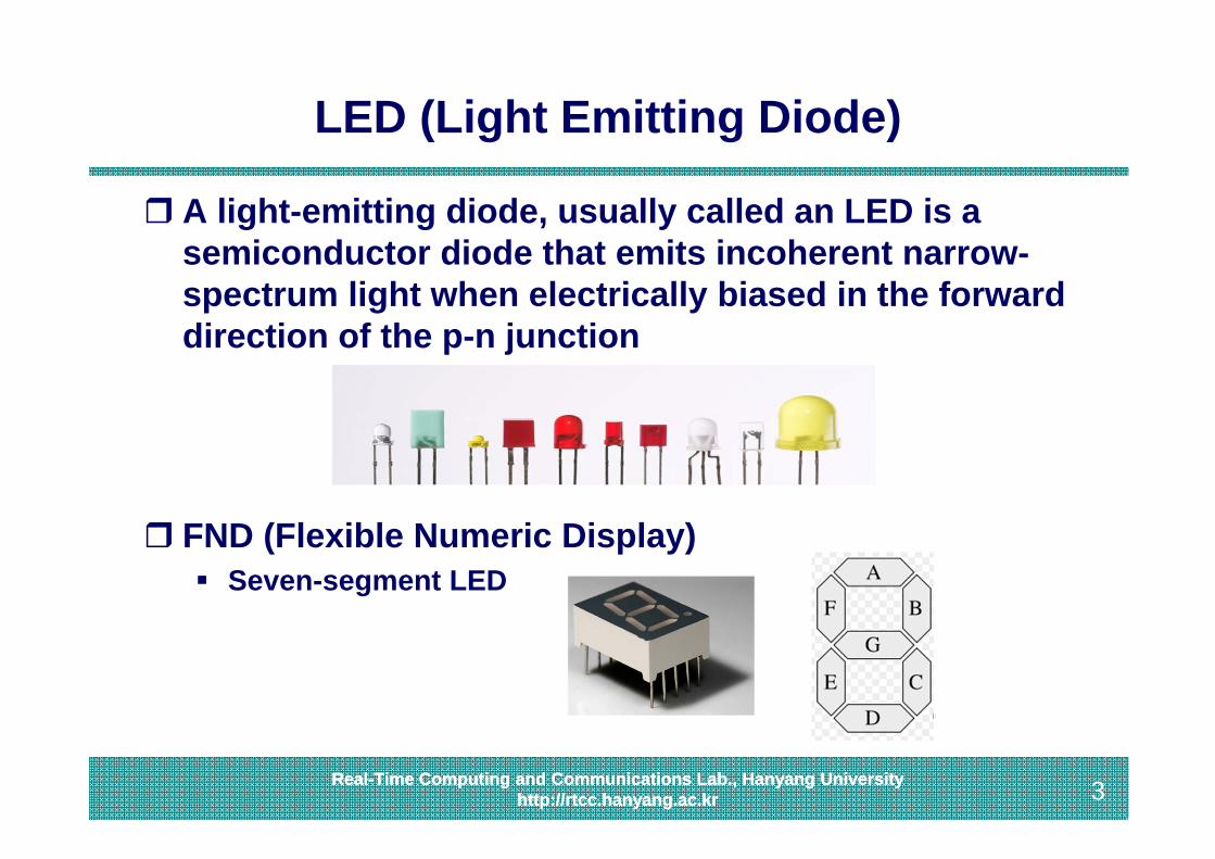
A light-emitting diode, usually called an LED is a semiconductor diode that emits incoherent narrow-spectrum light when electrically biased in the forward direction of the p-n junction
FND (Flexible Numeric Display) Seven-segment LED
4Real-Time Computing and Communications Lab., Hanyang University
http://rtcc.hanyang.ac.kr 4Real-Time Computing and Communications Lab., Hanyang Universityhttp://rtcc.hanyang.ac.kr
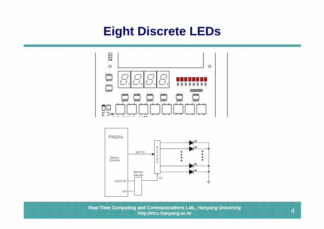
Eight Discrete LEDs
5Real-Time Computing and Communications Lab., Hanyang University
http://rtcc.hanyang.ac.kr 5Real-Time Computing and Communications Lab., Hanyang Universityhttp://rtcc.hanyang.ac.kr
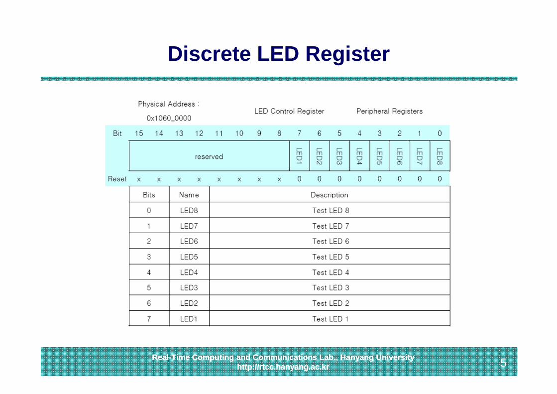
Discrete LED Register

6Real-Time Computing and Communications Lab., Hanyang University
http://rtcc.hanyang.ac.kr 6Real-Time Computing and Communications Lab., Hanyang Universityhttp://rtcc.hanyang.ac.kr
Programming Discrete LEDs
Blink LEDs for 1 second
#define LED_BASE 0x10600000
void blink_led (){
unsigned* led_addr = LED_BASE;unsigned led_val = 1;int blink_count = 8;int blink_delay = 1000000;int I;
for (i=0; i<blink_count; i++) {*led_addr = led_val;led_val << 1;usleep(blink_delay);
}}
When an MMU-enabled operating systemlike Linux is used, an appropriate virtualaddress must be obtained first.
The code should then be changed to aim at the virtual address instead of the physical address.
In Linux, the mmap function can return a virtual address from a given physicaladdress.
7Real-Time Computing and Communications Lab., Hanyang University
http://rtcc.hanyang.ac.kr 7Real-Time Computing and Communications Lab., Hanyang Universityhttp://rtcc.hanyang.ac.kr
Topics Covered
1. Discrete LEDs2. Seven-Segment LEDs3. Character LCD4. Keypads5. Touch Screens

8Real-Time Computing and Communications Lab., Hanyang University
http://rtcc.hanyang.ac.kr 8Real-Time Computing and Communications Lab., Hanyang Universityhttp://rtcc.hanyang.ac.kr
Four Seven-Segment LEDs
9Real-Time Computing and Communications Lab., Hanyang University
http://rtcc.hanyang.ac.kr 9Real-Time Computing and Communications Lab., Hanyang Universityhttp://rtcc.hanyang.ac.kr
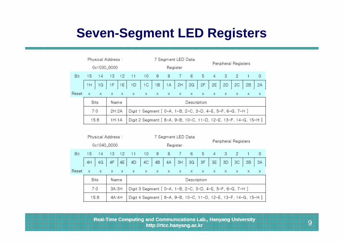
Seven-Segment LED Registers
10Real-Time Computing and Communications Lab., Hanyang University
http://rtcc.hanyang.ac.kr 10Real-Time Computing and Communications Lab., Hanyang Universityhttp://rtcc.hanyang.ac.kr
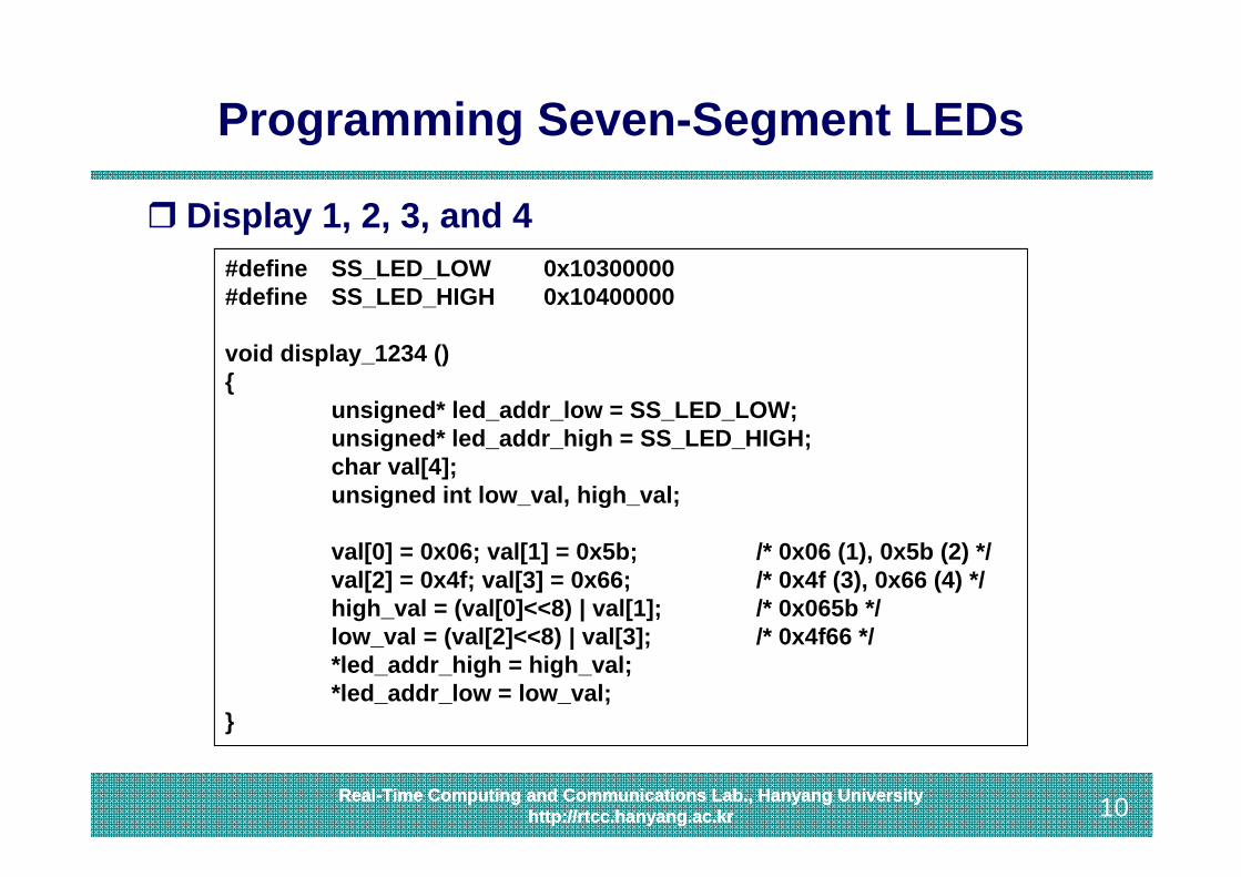
Programming Seven-Segment LEDs
Display 1, 2, 3, and 4#define SS_LED_LOW 0x10300000#define SS_LED_HIGH 0x10400000
void display_1234 (){
unsigned* led_addr_low = SS_LED_LOW;unsigned* led_addr_high = SS_LED_HIGH;char val[4];unsigned int low_val, high_val;
val[0] = 0x06; val[1] = 0x5b; /* 0x06 (1), 0x5b (2) */val[2] = 0x4f; val[3] = 0x66; /* 0x4f (3), 0x66 (4) */high_val = (val[0]<<8) | val[1]; /* 0x065b */low_val = (val[2]<<8) | val[3]; /* 0x4f66 */*led_addr_high = high_val;*led_addr_low = low_val;
}
11Real-Time Computing and Communications Lab., Hanyang University
http://rtcc.hanyang.ac.kr 11Real-Time Computing and Communications Lab., Hanyang Universityhttp://rtcc.hanyang.ac.kr
Topics Covered
1. Discrete LEDs2. Seven-Segment LEDs3. Character LCD4. Keypads5. Touch Screens
12Real-Time Computing and Communications Lab., Hanyang University
http://rtcc.hanyang.ac.kr 12Real-Time Computing and Communications Lab., Hanyang Universityhttp://rtcc.hanyang.ac.kr
LCD (Liquid Crystal Display)
A liquid crystal display (LCD) is a thin, flat display device made up of any number of color or monochrome pixels arrayed in front of a light source or reflector It is often utilized in battery-powered electronic devices
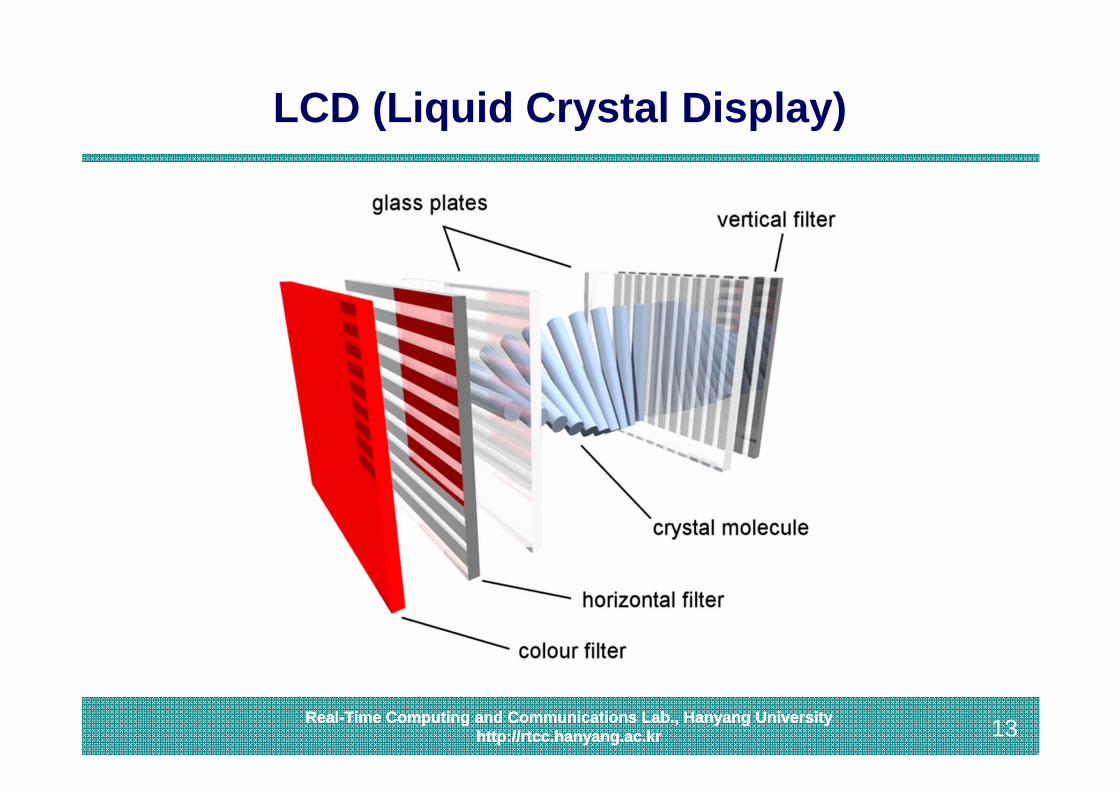
because it uses very small amounts of electric power Each pixel of an LCD typically consists of a layer of
molecules aligned between two transparent electrodes, and two polarizing filters
13Real-Time Computing and Communications Lab., Hanyang University
http://rtcc.hanyang.ac.kr 13Real-Time Computing and Communications Lab., Hanyang Universityhttp://rtcc.hanyang.ac.kr
LCD (Liquid Crystal Display)
14Real-Time Computing and Communications Lab., Hanyang University
http://rtcc.hanyang.ac.kr 14Real-Time Computing and Communications Lab., Hanyang Universityhttp://rtcc.hanyang.ac.kr
LCD (Liquid Crystal Display)
Two types Passive Matrix: STN-LCD (Super Twisted Nematic LCD) Active Matrix: TFT-LCD (Thin-Film Transistors LCD)
• Better response time, brightness, and sharpness
Two types from a SW perspective Character LCD
• Support for text mode Graphics LCD
• Support both for text and graphics mode
15Real-Time Computing and Communications Lab., Hanyang University
http://rtcc.hanyang.ac.kr 15Real-Time Computing and Communications Lab., Hanyang Universityhttp://rtcc.hanyang.ac.kr
Character LCD
Character LCD modules are available from a wide range of manufacturers and should all be compatible with the Hitachi HD44780 HD44780 Character LCD is an industry standard liquid crystal
display (LCD) display device designed for interfacing with embedded systems
Thus, it suffices to consider a typical example Here we will investigate CM2020S1LY-K from Data Image,
which is equipped in HBE MPOS-II
16Real-Time Computing and Communications Lab., Hanyang University
http://rtcc.hanyang.ac.kr 16Real-Time Computing and Communications Lab., Hanyang Universityhttp://rtcc.hanyang.ac.kr
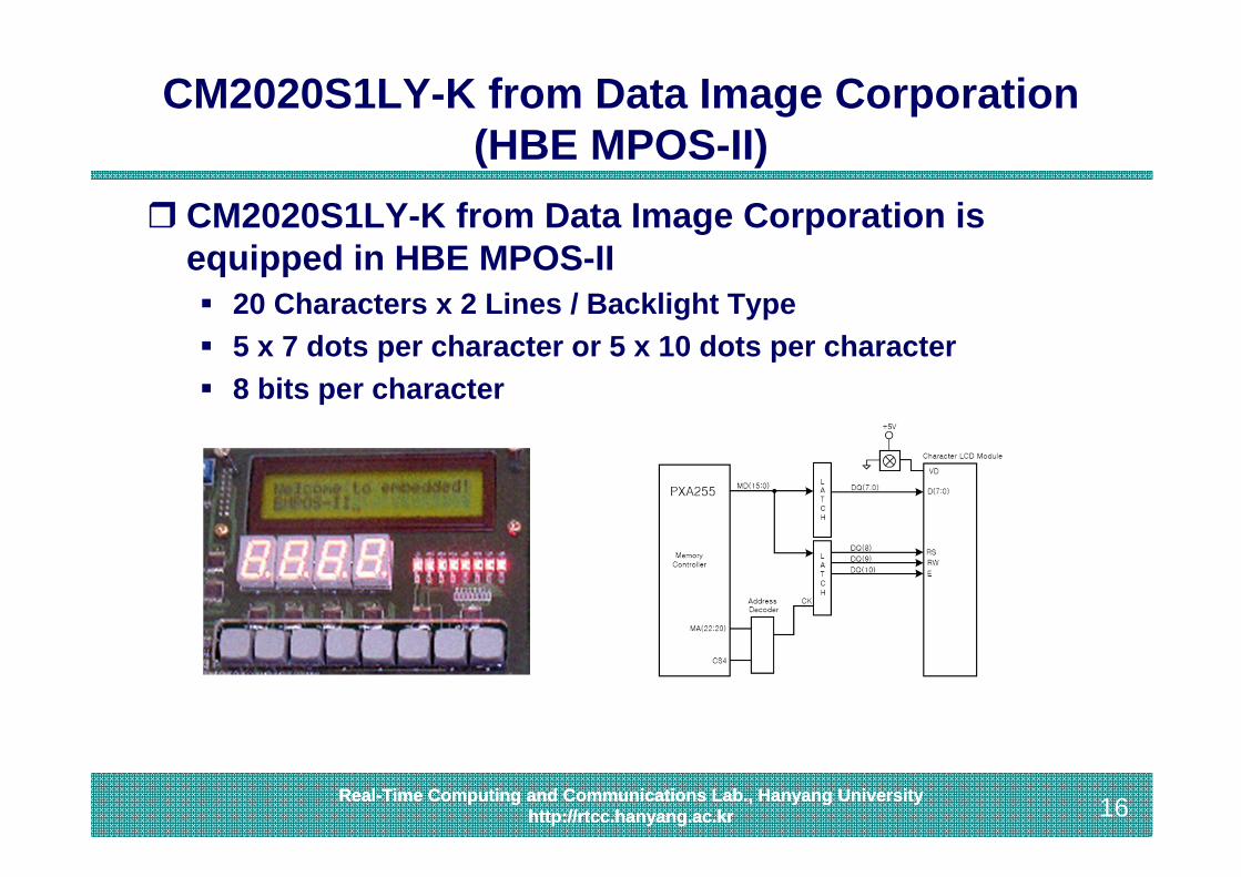
CM2020S1LY-K from Data Image Corporation (HBE MPOS-II)
CM2020S1LY-K from Data Image Corporation is equipped in HBE MPOS-II 20 Characters x 2 Lines / Backlight Type 5 x 7 dots per character or 5 x 10 dots per character 8 bits per character
17Real-Time Computing and Communications Lab., Hanyang University
http://rtcc.hanyang.ac.kr 17Real-Time Computing and Communications Lab., Hanyang Universityhttp://rtcc.hanyang.ac.kr
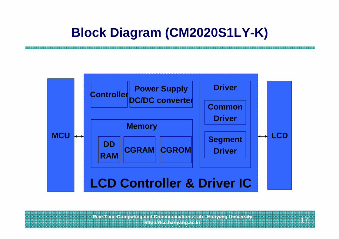
Block Diagram (CM2020S1LY-K)
LCD Controller & Driver IC
MCUCG
RAMCG
ROM
LCD
ControllerPower Supply
DC/DC converter
Memory
DDRAM
Driver
CommonDriver
SegmentDriverCGRAM CGROM

18Real-Time Computing and Communications Lab., Hanyang University
http://rtcc.hanyang.ac.kr 18Real-Time Computing and Communications Lab., Hanyang Universityhttp://rtcc.hanyang.ac.kr
Another Block Diagram(Samsung 16COM/40SEG)
19Real-Time Computing and Communications Lab., Hanyang University
http://rtcc.hanyang.ac.kr 19Real-Time Computing and Communications Lab., Hanyang Universityhttp://rtcc.hanyang.ac.kr
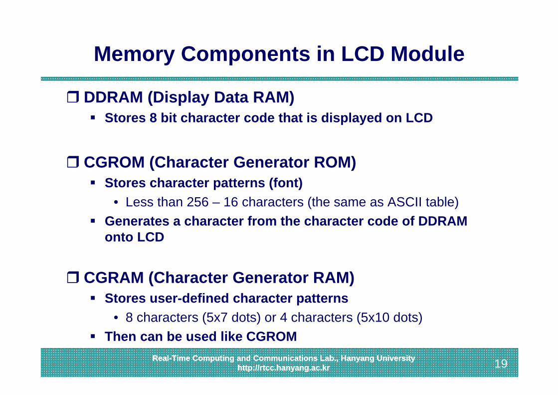
Memory Components in LCD Module
DDRAM (Display Data RAM) Stores 8 bit character code that is displayed on LCD
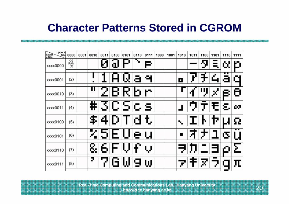
CGROM (Character Generator ROM) Stores character patterns (font)
• Less than 256 – 16 characters (the same as ASCII table) Generates a character from the character code of DDRAM
onto LCD
CGRAM (Character Generator RAM) Stores user-defined character patterns
• 8 characters (5x7 dots) or 4 characters (5x10 dots) Then can be used like CGROM
20Real-Time Computing and Communications Lab., Hanyang University
http://rtcc.hanyang.ac.kr 20Real-Time Computing and Communications Lab., Hanyang Universityhttp://rtcc.hanyang.ac.kr
Character Patterns Stored in CGROM
21Real-Time Computing and Communications Lab., Hanyang University
http://rtcc.hanyang.ac.kr 21Real-Time Computing and Communications Lab., Hanyang Universityhttp://rtcc.hanyang.ac.kr
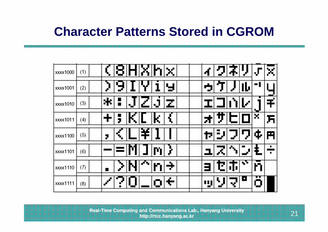
Character Patterns Stored in CGROM
22Real-Time Computing and Communications Lab., Hanyang University
http://rtcc.hanyang.ac.kr 22Real-Time Computing and Communications Lab., Hanyang Universityhttp://rtcc.hanyang.ac.kr
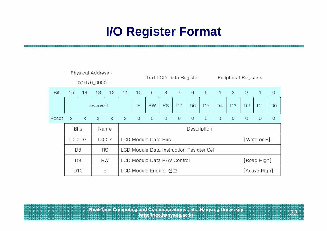
I/O Register Format
23Real-Time Computing and Communications Lab., Hanyang University
http://rtcc.hanyang.ac.kr 23Real-Time Computing and Communications Lab., Hanyang Universityhttp://rtcc.hanyang.ac.kr
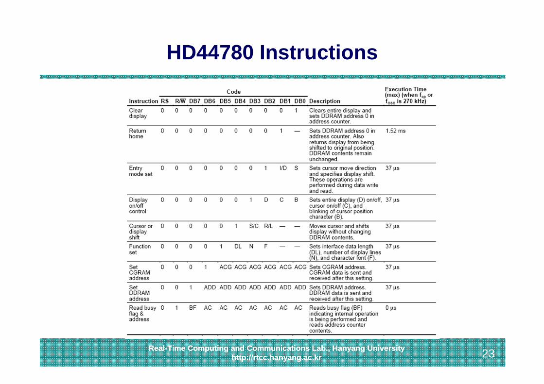
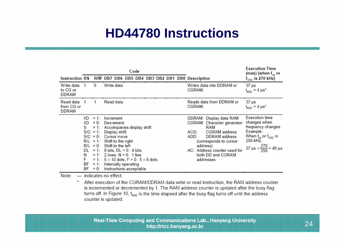
HD44780 Instructions
24Real-Time Computing and Communications Lab., Hanyang University
http://rtcc.hanyang.ac.kr 24Real-Time Computing and Communications Lab., Hanyang Universityhttp://rtcc.hanyang.ac.kr
HD44780 Instructions
25Real-Time Computing and Communications Lab., Hanyang University
http://rtcc.hanyang.ac.kr 25Real-Time Computing and Communications Lab., Hanyang Universityhttp://rtcc.hanyang.ac.kr
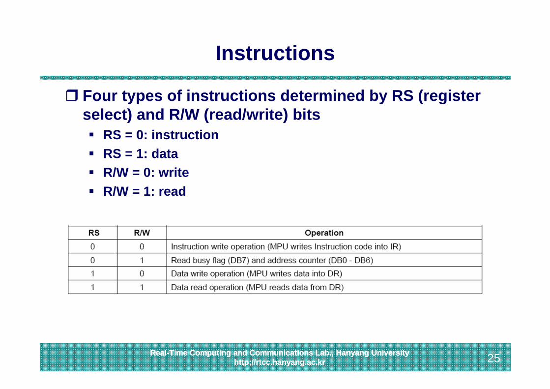
Instructions
Four types of instructions determined by RS (register select) and R/W (read/write) bits RS = 0: instruction RS = 1: data R/W = 0: write R/W = 1: read
26Real-Time Computing and Communications Lab., Hanyang University
http://rtcc.hanyang.ac.kr 26Real-Time Computing and Communications Lab., Hanyang Universityhttp://rtcc.hanyang.ac.kr
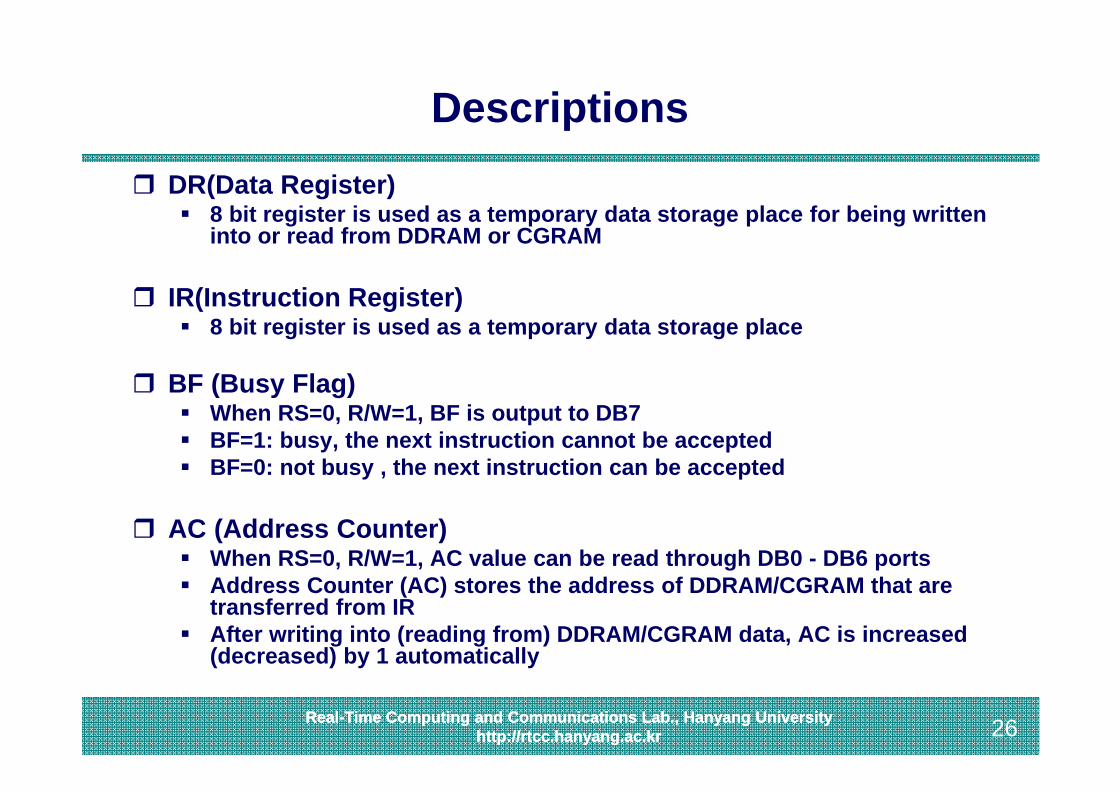
Descriptions DR(Data Register)
8 bit register is used as a temporary data storage place for being written into or read from DDRAM or CGRAM
IR(Instruction Register) 8 bit register is used as a temporary data storage place
BF (Busy Flag) When RS=0, R/W=1, BF is output to DB7 BF=1: busy, the next instruction cannot be accepted BF=0: not busy , the next instruction can be accepted
AC (Address Counter) When RS=0, R/W=1, AC value can be read through DB0 - DB6 ports Address Counter (AC) stores the address of DDRAM/CGRAM that are
transferred from IR After writing into (reading from) DDRAM/CGRAM data, AC is increased
(decreased) by 1 automatically

27Real-Time Computing and Communications Lab., Hanyang University
http://rtcc.hanyang.ac.kr 27Real-Time Computing and Communications Lab., Hanyang Universityhttp://rtcc.hanyang.ac.kr
IR and DR
I/OBuf.
CGRAM
CGROM
+5VRS
R/WE
D0~D7
Vo0V
Instruction registerD7D6D5D4D3D2D1D0
LCDRS=0
DDRAM
8
Data registerD7D6D5D4D3D2D1D0
RS=1
88
8
AC6AC5AC4AC3AC2AC1AC0
28Real-Time Computing and Communications Lab., Hanyang University
http://rtcc.hanyang.ac.kr 28Real-Time Computing and Communications Lab., Hanyang Universityhttp://rtcc.hanyang.ac.kr
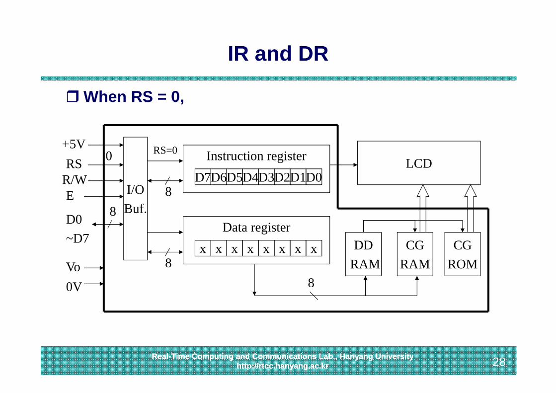
IR and DR
When RS = 0,
I/OBuf.
CGRAM
CGROM
+5VRS
R/WE
D0~D7
Vo0V
Instruction registerD7D6D5D4D3D2D1D0
Data registerx x x x x x x x
LCDRS=0
DDRAM
8
88
8
0
29Real-Time Computing and Communications Lab., Hanyang University
http://rtcc.hanyang.ac.kr 29Real-Time Computing and Communications Lab., Hanyang Universityhttp://rtcc.hanyang.ac.kr
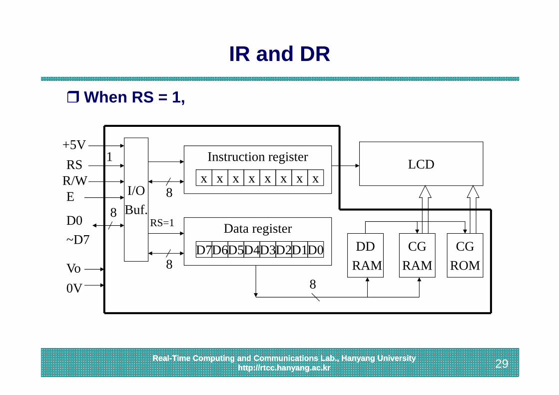
IR and DR
When RS = 1,
I/OBuf.
CGRAM
CGROM
+5VRS
R/WE
D0~D7
Vo0V
Instruction registerx x x x x x x x
Data registerD7D6D5D4D3D2D1D0
LCD
RS=1
DDRAM
8
88
8
1

30Real-Time Computing and Communications Lab., Hanyang University
http://rtcc.hanyang.ac.kr 30Real-Time Computing and Communications Lab., Hanyang Universityhttp://rtcc.hanyang.ac.kr
DDRAM Addresses

31Real-Time Computing and Communications Lab., Hanyang University
http://rtcc.hanyang.ac.kr 31Real-Time Computing and Communications Lab., Hanyang Universityhttp://rtcc.hanyang.ac.kr
Function Set Instruction
Sets the following Interface data length (DL)
• DL=1 (8 bit data line), DL=0 (4 bit data line) Number of display lines
• N=0 (1 line), N=1 (2 lines) Character font
• F=0: 5 x 8 dots per character• F=1: 5 x 10 dots per character
RS0
R/W0
DB70
DB60
DB51
DB4DL
DB3N
DB2F
DB1*
DB0*
32Real-Time Computing and Communications Lab., Hanyang University
http://rtcc.hanyang.ac.kr 32Real-Time Computing and Communications Lab., Hanyang Universityhttp://rtcc.hanyang.ac.kr
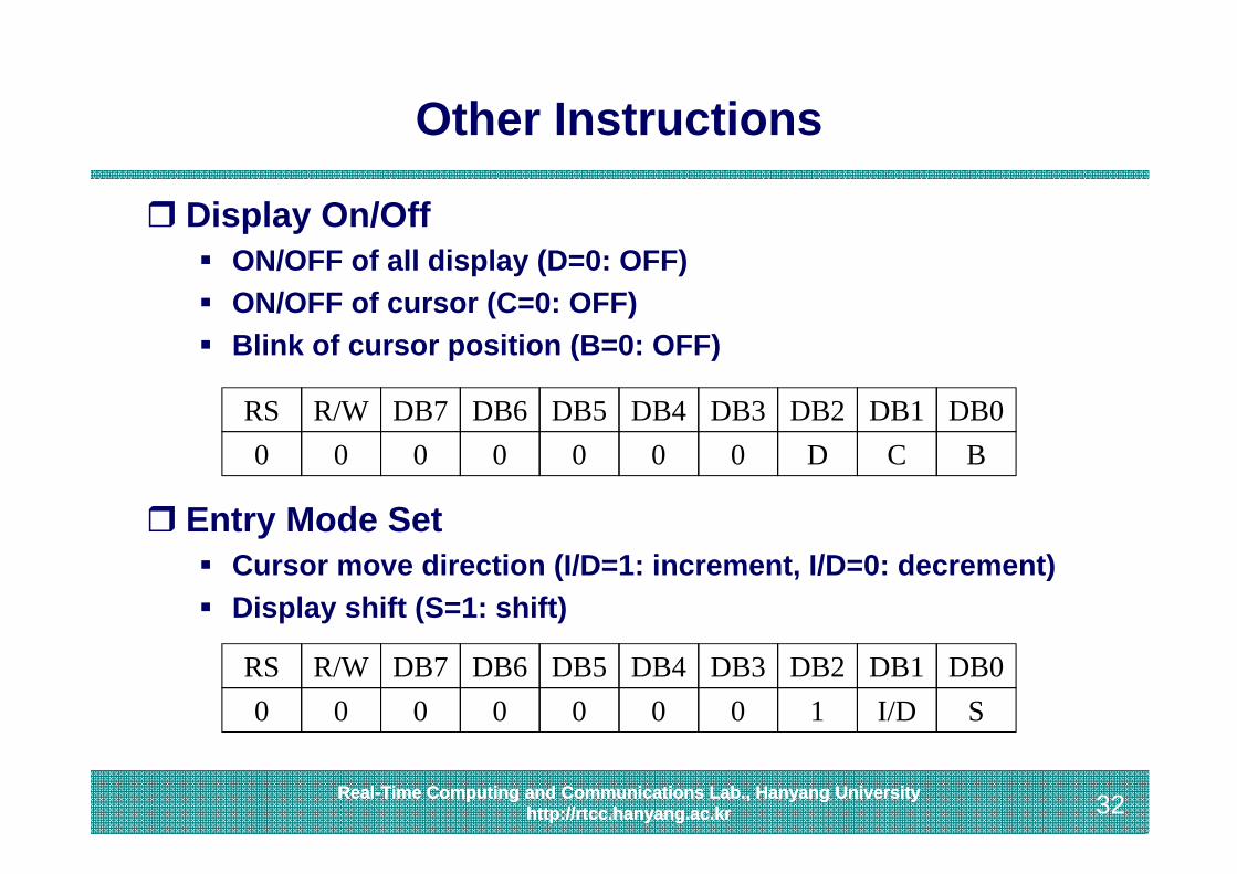
Other Instructions
Display On/Off ON/OFF of all display (D=0: OFF) ON/OFF of cursor (C=0: OFF) Blink of cursor position (B=0: OFF)
Entry Mode Set Cursor move direction (I/D=1: increment, I/D=0: decrement) Display shift (S=1: shift)
RS0
R/W0
DB70
DB60
DB50
DB40
DB30
DB2D
DB1C
DB0B
RS0
R/W0
DB70
DB60
DB50
DB40
DB30
DB21
DB1I/D
DB0S
33Real-Time Computing and Communications Lab., Hanyang University
http://rtcc.hanyang.ac.kr 33Real-Time Computing and Communications Lab., Hanyang Universityhttp://rtcc.hanyang.ac.kr
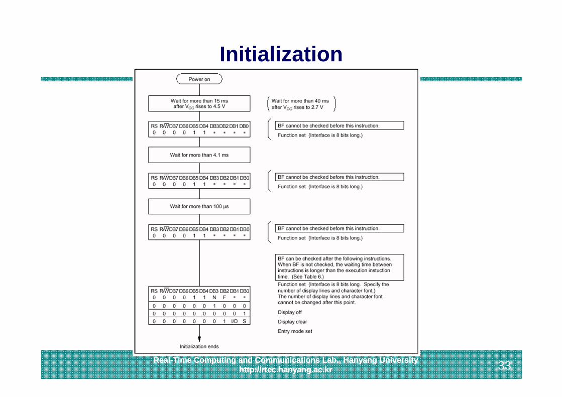
Initialization
34Real-Time Computing and Communications Lab., Hanyang University
http://rtcc.hanyang.ac.kr 34Real-Time Computing and Communications Lab., Hanyang Universityhttp://rtcc.hanyang.ac.kr
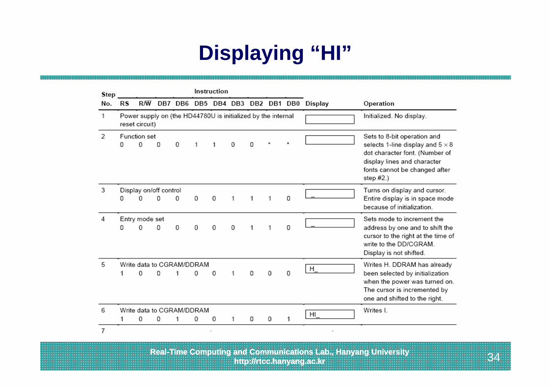
Displaying “HI”
35Real-Time Computing and Communications Lab., Hanyang University
http://rtcc.hanyang.ac.kr 35Real-Time Computing and Communications Lab., Hanyang Universityhttp://rtcc.hanyang.ac.kr
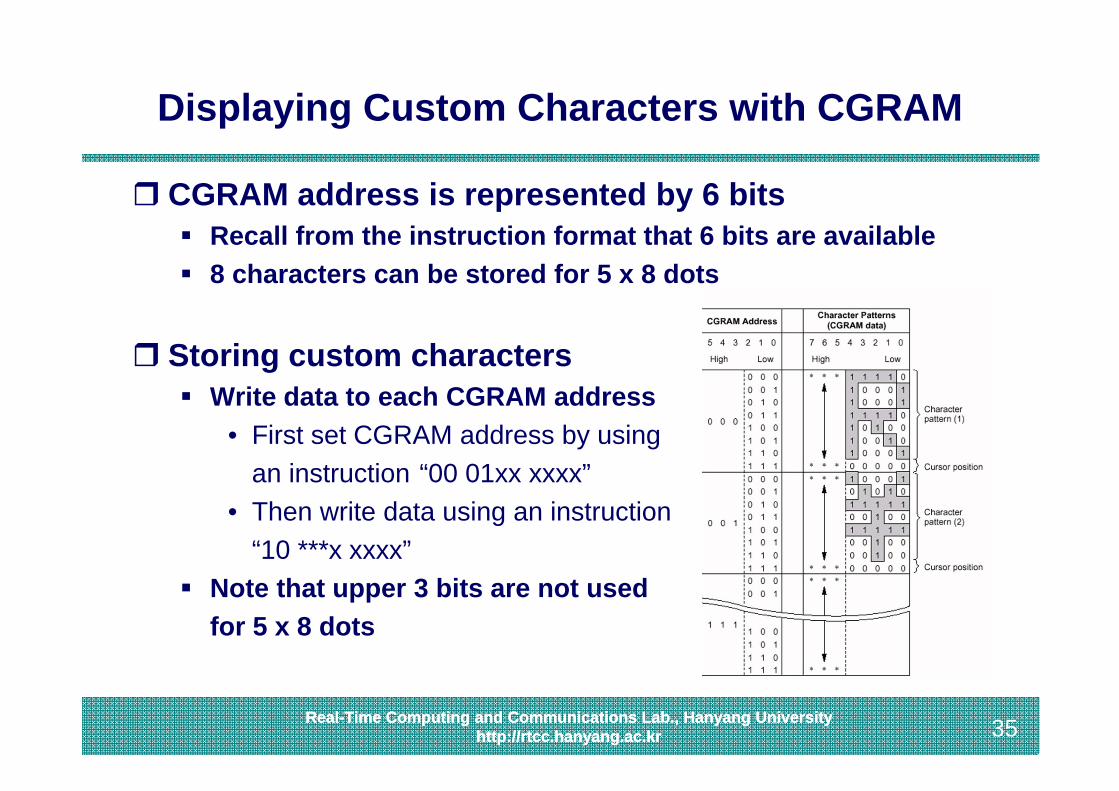
Displaying Custom Characters with CGRAM
CGRAM address is represented by 6 bits Recall from the instruction format that 6 bits are available 8 characters can be stored for 5 x 8 dots
Storing custom characters Write data to each CGRAM address
• First set CGRAM address by usingan instruction “00 01xx xxxx”
• Then write data using an instruction“10 ***x xxxx”
Note that upper 3 bits are not used for 5 x 8 dots
36Real-Time Computing and Communications Lab., Hanyang University
http://rtcc.hanyang.ac.kr 36Real-Time Computing and Communications Lab., Hanyang Universityhttp://rtcc.hanyang.ac.kr
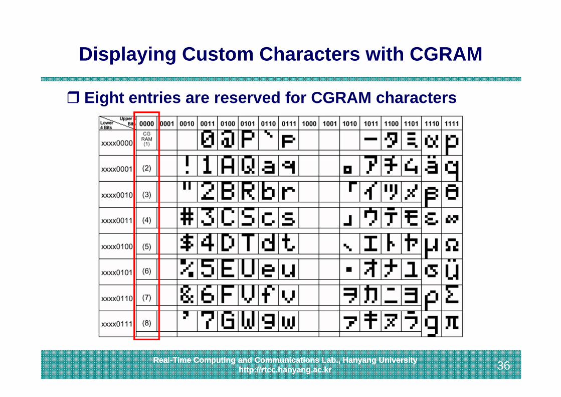
Displaying Custom Characters with CGRAM
Eight entries are reserved for CGRAM characters
37Real-Time Computing and Communications Lab., Hanyang University
http://rtcc.hanyang.ac.kr 37Real-Time Computing and Communications Lab., Hanyang Universityhttp://rtcc.hanyang.ac.kr
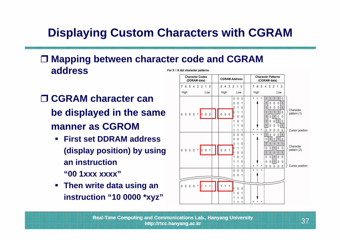
Displaying Custom Characters with CGRAM
Mapping between character code and CGRAM address
CGRAM character canbe displayed in the samemanner as CGROM First set DDRAM address
(display position) by usingan instruction “00 1xxx xxxx”
Then write data using an instruction “10 0000 *xyz”
38Real-Time Computing and Communications Lab., Hanyang University
http://rtcc.hanyang.ac.kr 38Real-Time Computing and Communications Lab., Hanyang Universityhttp://rtcc.hanyang.ac.kr
Topics Covered
1. Discrete LEDs2. Seven-Segment LEDs3. Character LCD4. Keypads5. Touch Screens
39Real-Time Computing and Communications Lab., Hanyang University
http://rtcc.hanyang.ac.kr 39Real-Time Computing and Communications Lab., Hanyang Universityhttp://rtcc.hanyang.ac.kr
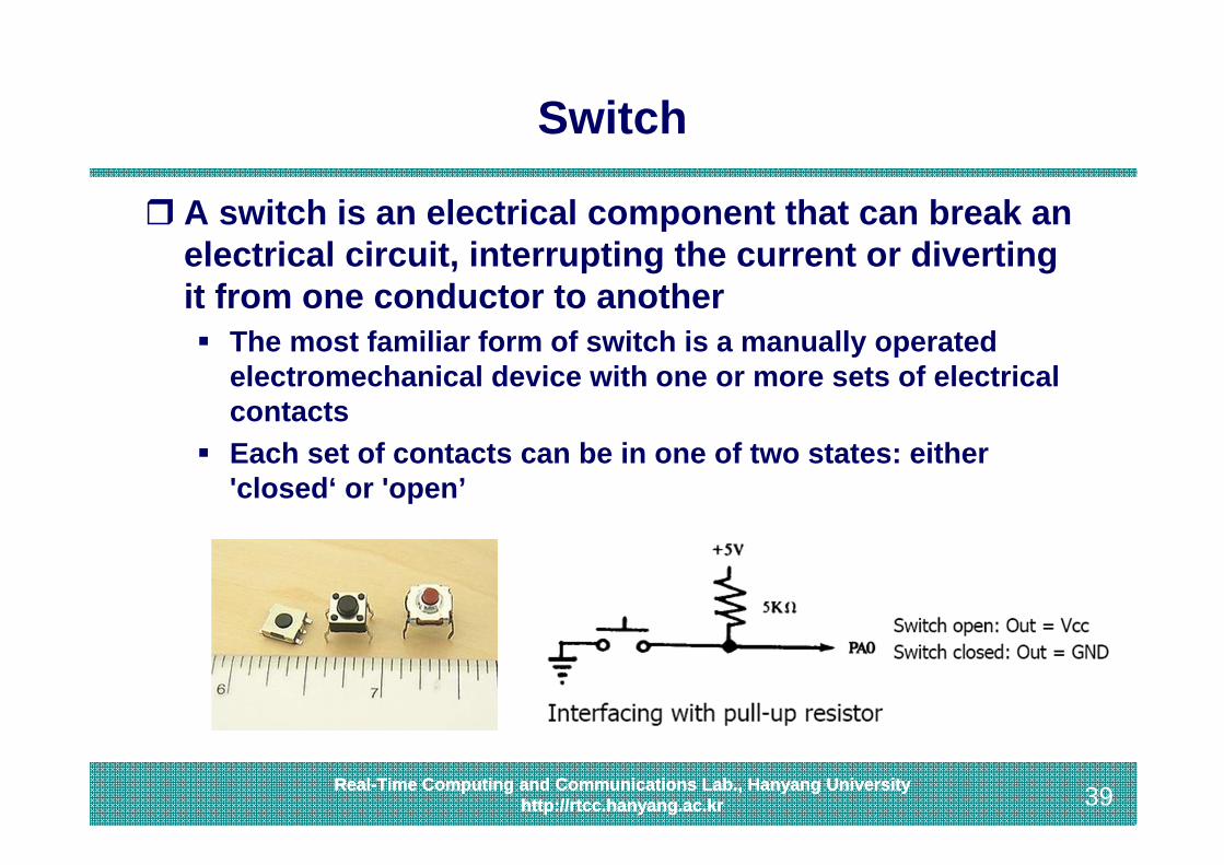
Switch
A switch is an electrical component that can break an electrical circuit, interrupting the current or diverting it from one conductor to another The most familiar form of switch is a manually operated
electromechanical device with one or more sets of electrical contacts
Each set of contacts can be in one of two states: either 'closed‘ or 'open’
40Real-Time Computing and Communications Lab., Hanyang University
http://rtcc.hanyang.ac.kr 40Real-Time Computing and Communications Lab., Hanyang Universityhttp://rtcc.hanyang.ac.kr
Contact Bounce (Chatter)
Contact bounce is a common problem with mechanical switches Switch contacts are usually made of springy metals that are
forced into contact by an actuator When the contacts strike together, their momentum and
elasticity act together to cause bounce The result is a rapidly pulsed electrical current instead of a
clean transition from zero to full current
41Real-Time Computing and Communications Lab., Hanyang University
http://rtcc.hanyang.ac.kr 41Real-Time Computing and Communications Lab., Hanyang Universityhttp://rtcc.hanyang.ac.kr
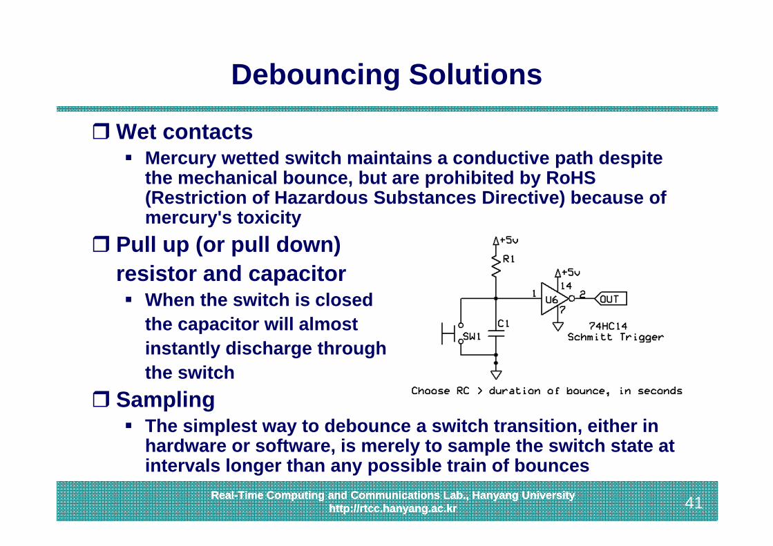
Debouncing Solutions
Wet contacts Mercury wetted switch maintains a conductive path despite
the mechanical bounce, but are prohibited by RoHS(Restriction of Hazardous Substances Directive) because of mercury's toxicity
Pull up (or pull down) resistor and capacitor When the switch is closed
the capacitor will almost instantly discharge through the switch
Sampling The simplest way to debounce a switch transition, either in
hardware or software, is merely to sample the switch state at intervals longer than any possible train of bounces
42Real-Time Computing and Communications Lab., Hanyang University
http://rtcc.hanyang.ac.kr 42Real-Time Computing and Communications Lab., Hanyang Universityhttp://rtcc.hanyang.ac.kr
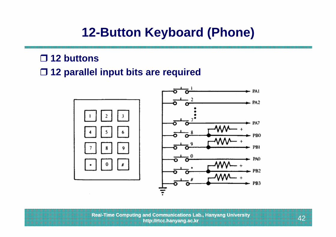
12-Button Keyboard (Phone)
12 buttons 12 parallel input bits are required

43Real-Time Computing and Communications Lab., Hanyang University
http://rtcc.hanyang.ac.kr 43Real-Time Computing and Communications Lab., Hanyang Universityhttp://rtcc.hanyang.ac.kr
Matrix Keypad
A matrix keypad is a set of switches arranged so that they fall into rows and columns (a matrix) The top terminals of every switch in the same row are
internally connected together and also connected to an external pin
The bottom terminals of every switch in the same column are internally connected together and also connected to a different external pin
44Real-Time Computing and Communications Lab., Hanyang University
http://rtcc.hanyang.ac.kr 44Real-Time Computing and Communications Lab., Hanyang Universityhttp://rtcc.hanyang.ac.kr
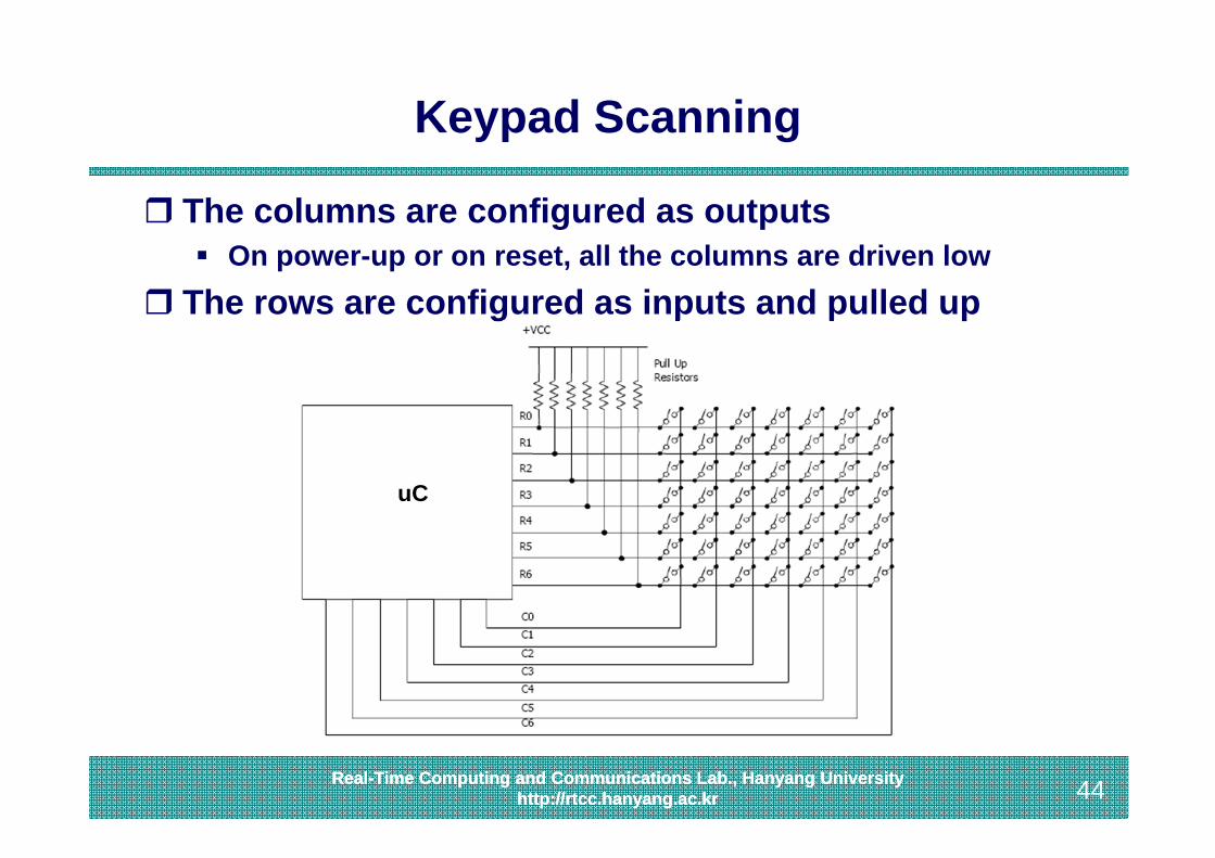
Keypad Scanning
The columns are configured as outputs On power-up or on reset, all the columns are driven low
The rows are configured as inputs and pulled up
uC
45Real-Time Computing and Communications Lab., Hanyang University
http://rtcc.hanyang.ac.kr 45Real-Time Computing and Communications Lab., Hanyang Universityhttp://rtcc.hanyang.ac.kr
Keypad Scanning
Whenever a key is pressed, the row and column corresponding to that key get connected, causing its row input to go low
SW or HW should then start actively scanning each column one by one to determine the location of the key that was pressed The column which is being scanned is made low while others
are tri-stated If the key which is pressed lies in this column, one of the row
inputs will go low, revealing its location When the required column is detected, it should maintain the
column at ground and checks whether the same row is still low after a small delay
• This is done in order to debounce the key press
46Real-Time Computing and Communications Lab., Hanyang University
http://rtcc.hanyang.ac.kr 46Real-Time Computing and Communications Lab., Hanyang Universityhttp://rtcc.hanyang.ac.kr
Topics Covered
1. Discrete LEDs2. Seven-Segment LEDs3. Character LCD4. Keypads5. Touch Screens
47Real-Time Computing and Communications Lab., Hanyang University
http://rtcc.hanyang.ac.kr 47Real-Time Computing and Communications Lab., Hanyang Universityhttp://rtcc.hanyang.ac.kr
Touchscreen
A touchscreen is a display which can detect the presence and location of a touch within the display area The term generally refers to touch or contact to the display of
the device by a finger or hand Touchscreens can also sense other passive objects, such as
a stylus
48Real-Time Computing and Communications Lab., Hanyang University
http://rtcc.hanyang.ac.kr 48Real-Time Computing and Communications Lab., Hanyang Universityhttp://rtcc.hanyang.ac.kr
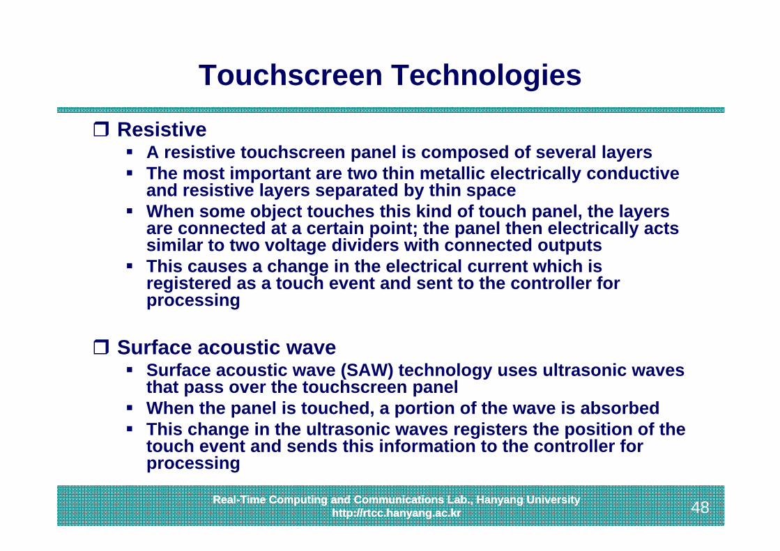
Touchscreen Technologies Resistive
A resistive touchscreen panel is composed of several layers The most important are two thin metallic electrically conductive
and resistive layers separated by thin space When some object touches this kind of touch panel, the layers
are connected at a certain point; the panel then electrically acts similar to two voltage dividers with connected outputs
This causes a change in the electrical current which is registered as a touch event and sent to the controller for processing
Surface acoustic wave Surface acoustic wave (SAW) technology uses ultrasonic waves
that pass over the touchscreen panel When the panel is touched, a portion of the wave is absorbed This change in the ultrasonic waves registers the position of the
touch event and sends this information to the controller for processing

49Real-Time Computing and Communications Lab., Hanyang University
http://rtcc.hanyang.ac.kr 49Real-Time Computing and Communications Lab., Hanyang Universityhttp://rtcc.hanyang.ac.kr
Touchscreen Technologies
Capacitive A capacitive touchscreen panel is coated with a material, typically
indium tin oxide, that conducts a continuous electrical current across the sensor
The sensor therefore exhibits a precisely controlled field of stored electrons in both the horizontal and vertical axes - it achieves capacitance
The human body is also an electrical device which has stored electrons and therefore also exhibits capacitance
Capacitive sensors work based on proximity, and do not have to be directly touched to be triggered
It is a durable technology that is used in a wide range of applications It has a higher clarity than Resistive technology, but it only responds to
finger contact and will not work with a gloved hand or pen stylus unless the stylus is conductive and transmits the user's capacitance
Capacitive touch screens can also support Multitouch (several fingers) Examples include Apple Inc.'s iPhone and iPod touch, and HTC's G1 &
HTC Magic
50Real-Time Computing and Communications Lab., Hanyang University
http://rtcc.hanyang.ac.kr 50Real-Time Computing and Communications Lab., Hanyang Universityhttp://rtcc.hanyang.ac.kr
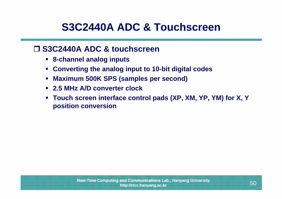
S3C2440A ADC & Touchscreen
S3C2440A ADC & touchscreen 8-channel analog inputs Converting the analog input to 10-bit digital codes Maximum 500K SPS (samples per second) 2.5 MHz A/D converter clock Touch screen interface control pads (XP, XM, YP, YM) for X, Y
position conversion
51Real-Time Computing and Communications Lab., Hanyang University
http://rtcc.hanyang.ac.kr 51Real-Time Computing and Communications Lab., Hanyang Universityhttp://rtcc.hanyang.ac.kr
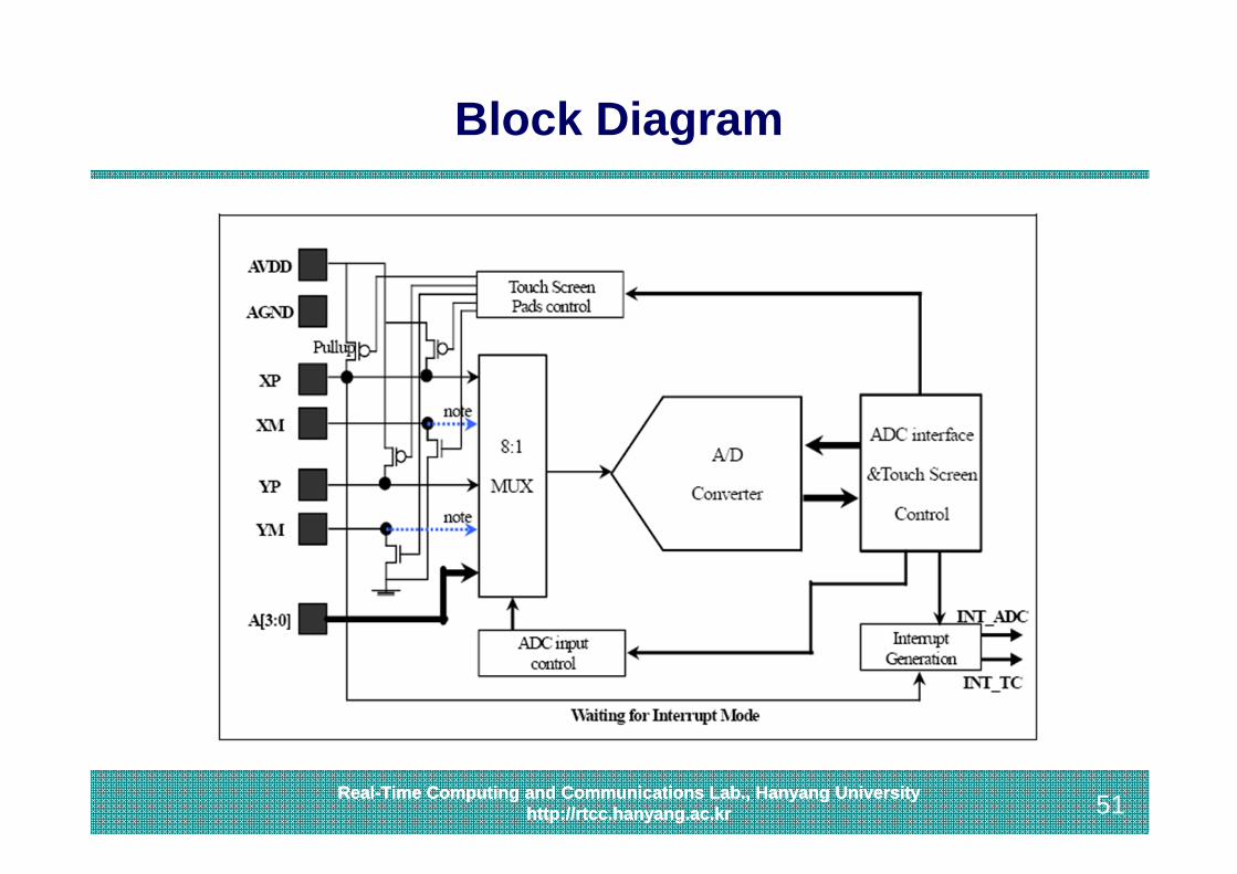
Block Diagram
52Real-Time Computing and Communications Lab., Hanyang University
http://rtcc.hanyang.ac.kr 52Real-Time Computing and Communications Lab., Hanyang Universityhttp://rtcc.hanyang.ac.kr
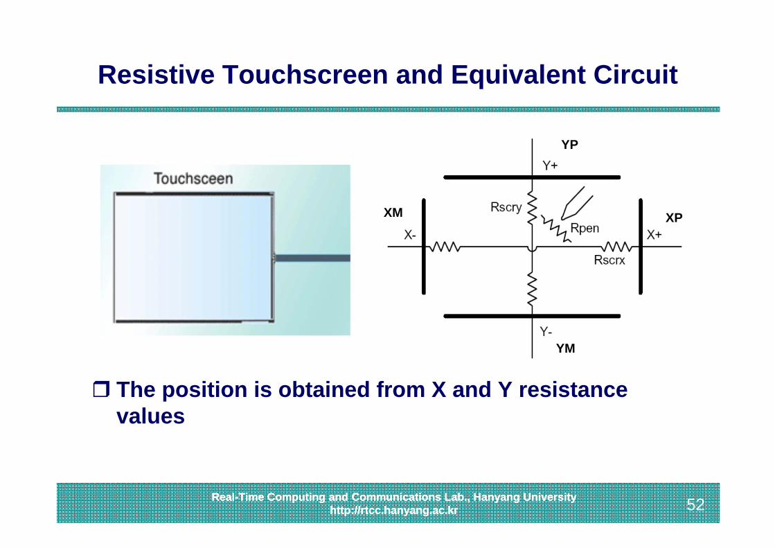
Resistive Touchscreen and Equivalent Circuit
The position is obtained from X and Y resistance values
YP
YM
XM XP