inrush current in transformer and its mitigation
TRANSCRIPT
© 2018 JETIR November 2018, Volume 5, Issue 11 www.jetir.org (ISSN-2349-5162)
JETIRK006146 Journal of Emerging Technologies and Innovative Research (JETIR) www.jetir.org 961
Inrush Current in Transformer And Its Mitigation
Roopal R Kapadia1, Dr.R.M.Patel2, Dr. J.J.Patel3 1Research Scholar,Electrical Engineering, GTU, Ahmedabad, Gujarat, India
2Dept. of Electrical Engineering, MITR, Rajkot, Gujarat, India
3Dept. of Electrical Engineering, GCET, Vallabh Vidyanagar, Gujarat, India
Abstract Power Transformer is most expensive apparatus of electrical power system. When Power transformer is energized from the de energized state, it experiences a large amount of
current which is known as inrush current. Inrush current impacts on winding of
transformer, causes of generation of harmonics and related Problems of power quality. Here, the effects of inrush current on power system and types of inrush current are
elaborated. Also methods for the inrush current mitigation by suitable means are discussed. .
Keywords: Inrush current, Residual flux, switching angle, Energization inrush, sympathetic
inrush, recovery inrush current.
INTRODUCTION
Power Transformer is one of the most important and expensive device of power system network.
Transformer is static equipment of power system network which transfer the electric energy from
one circuit to another circuit without change in frequency. When transformer energized large amount
of current is flow through the transformer primary winding called inrush Current [1]. Inrush current is
10 to 15 times than that of the rated current. In transformer inrush current remains high for several
cycle but it is slowly decreases and after some cycle it is reach at rated value of current. Inrush current
is either positive or negative direction due to its asymmetric properties. The inrush current has
numerous effects such as voltage distortion, harmonics, mechanical stress and mal operation of
protective relay. Maximum amount of inrush current is drawn by transformer when voltage is applied
to the transformer while there will be an instant of crossing through zero in voltage waveform.
Because, at the moment of transformer energization, secondary winding of transformer is open so
primary act as simple inductance. If applied voltage of power transformer is at zero degree,the inrush
current is maximum. Inrush current never generates any permanent fault in transformer but still that
creates the major problems in power system. So focus on the minimization of this incipient current is
essential in the power system Operation. Inrush current can be classified to three categories as
follows.
1. Energization inrush: Energization inrush current is mainly produced due to multiple times
energization of power transformer (Switching Phenomena), It results due to residual flux(Remanance)
which always remains in core of transformer due to Ferro magnetic properties of the transformer core
material [2].
2. Recovery inrush: This is type of inrush current is mainly generated when applied Voltage to the
power transformer is becoming normal (restore) after being subjected to the some kind of system
disturbances(Fault appearance) and upon its complete removal[2].
3. Sympathetic inrush: Such type of inrush current is mainly seen in Power System when numbers of
transformers are connected parallel and another one is energized to connect across it. That newly
energized transformer creates disturbance in the magnetic field of the remaining transformers of
network [2].
II. Factors Affecting the Inrush Current
Some factors which are responsible for inrush current in transformer are:
Switching angle: Switching angle of voltage depends on instant of transform energization as
per below equation of flux in transformer is given as below when the supply voltage to the
transformer is [3].As we know that,

© 2018 JETIR November 2018, Volume 5, Issue 11 www.jetir.org (ISSN-2349-5162)
JETIRK006146 Journal of Emerging Technologies and Innovative Research (JETIR) www.jetir.org 962
𝒗 = 𝑉𝑚 sin(wt + α) ----------------------- (1)
𝒗 = ndΦ/dt ---------------------------------- (2)
Φ = Φr + Φm cos(α) − Φm cos(wt + α) … … … … … … … … … … … … … … … … … (3)
Where α = Switching Instant.
From equation (3) derived values of flux for the various angle of switching instants are listed as
follows:
Table I. Switching angle Vs. Flux Amount
Switching
Instant
Flux Amount
α = 0° ∅ = 3∅m
α = 45° ∅ = 2.12∅m
α = 90° ∅ = 2∅m
It is obviously noted that inrush current depends on mainly two factors called residual flux and
switching angle of supply voltage as shown. It is clearly seen that in equation 1, when switching
instant of the voltage is zero(α = 0°) and ϕr = ϕm then the amplitude of the flux is three times of the
maximum flux (with w=wt) and to realization of this situation(∅= 3∅m),Primary winding of the
transformer draws very huge amount of magnetizing current,
Fig. 1 Inrush Phenomena at voltage switching with zero angle
The inrush current can be spitted into two parts called decaying DC and Distorted AC components.
The rate of the decay of this inrush current is usually very fast for the first few cycles and then
progressively become slow
Fig. 2 Voltage, flux and current at instant of inrush phenomena with remenance

© 2018 JETIR November 2018, Volume 5, Issue 11 www.jetir.org (ISSN-2349-5162)
JETIRK006146 Journal of Emerging Technologies and Innovative Research (JETIR) www.jetir.org 963
The typical wave shape of inrush current is as shown below:
Fig.3 Typical Inrush Current Waveform
Residual flux density: Transformer is made using the ferromagnetic materials and due to its core
hysteresis properties, little amount of flux remaining inside the core material after de energization
which is known as “residual flux” and the property is called “retentivity” of that material.
Fig. 4 Inrush Phenomena with switching with zero angle without remenece.
Inrush current is due to remanance, which again depends on the magnetic characteristics of material of
the core. Peak value o residual flux is usually taken as about 85 to 90 percentage of its maximum i.e.
the saturation value for different types of material respectively [1]. Table show the value of residual
flux (in Wb) for different ratings of power transformer.
Table II. Transformer Residual flux for various ratings of Transformers.
Transformer
(KVA)
300 80 50000
Residual
Flux (Wb)
0.3 0.8 13.0
Value of residual flux in transformer can be obtained by de energization instant of transformer.
Residual flux measurement is used for deciding the optimal instant of transformer energization for
minimizing the inrush current in control switching techniques [4].
Series resistance: The resistance of line between transformer and sources is the prime parameter in
case of inrush current. The damping effect offered by series resistance realized between the
transformer and the source reduces initial inrush current maximally and also speed up its decay rate
for inrush current. Transformer which is nearer to the source generally has higher inrush current than
others because of the low resistance of line. [1].
Source impedance: The peak value of inrush current in the transformer can be determined by the
source impedance in the power system. The maximum inrush can be transferred if when transformer
primary winding impedance and source impedance is same or transformer impedance is lower than
that of the source impedance. The transformer inrush current and impedance between the sources and
the energized transformer creates temporary voltage sags for the little time duration.[5].
Inrush under load: The inrush current crest is affected little by power factor of load when the
transformer is switched on load condition. When the transformer is switched on under heavy load
© 2018 JETIR November 2018, Volume 5, Issue 11 www.jetir.org (ISSN-2349-5162)
JETIRK006146 Journal of Emerging Technologies and Innovative Research (JETIR) www.jetir.org 964
(while power factor close to unity), the peak value of inrush current is very less. As Power factor
reduces, the inrush current peak is become higher [6].
Size of transformer: The value of inrush current is depends upon the size of Power transformer. The
large Power transformer having high ratings more than 1000 KVA produces lower inrush current for
longer time duration in terms of seconds while small rated power transformer of (less than1000 KVA)
is generates higher inrush current for small time duration in terms of milliseconds [7].
III. Effects of inrush current
Voltage distortion: When transformer is energized, and if transformer impedance is smaller than the
source impedance, voltage drop will occurs due to inrush current phenomena called voltage distortion.
It may affect the industrial costumer using sensitive load and equipment used in medical field etc. [5].
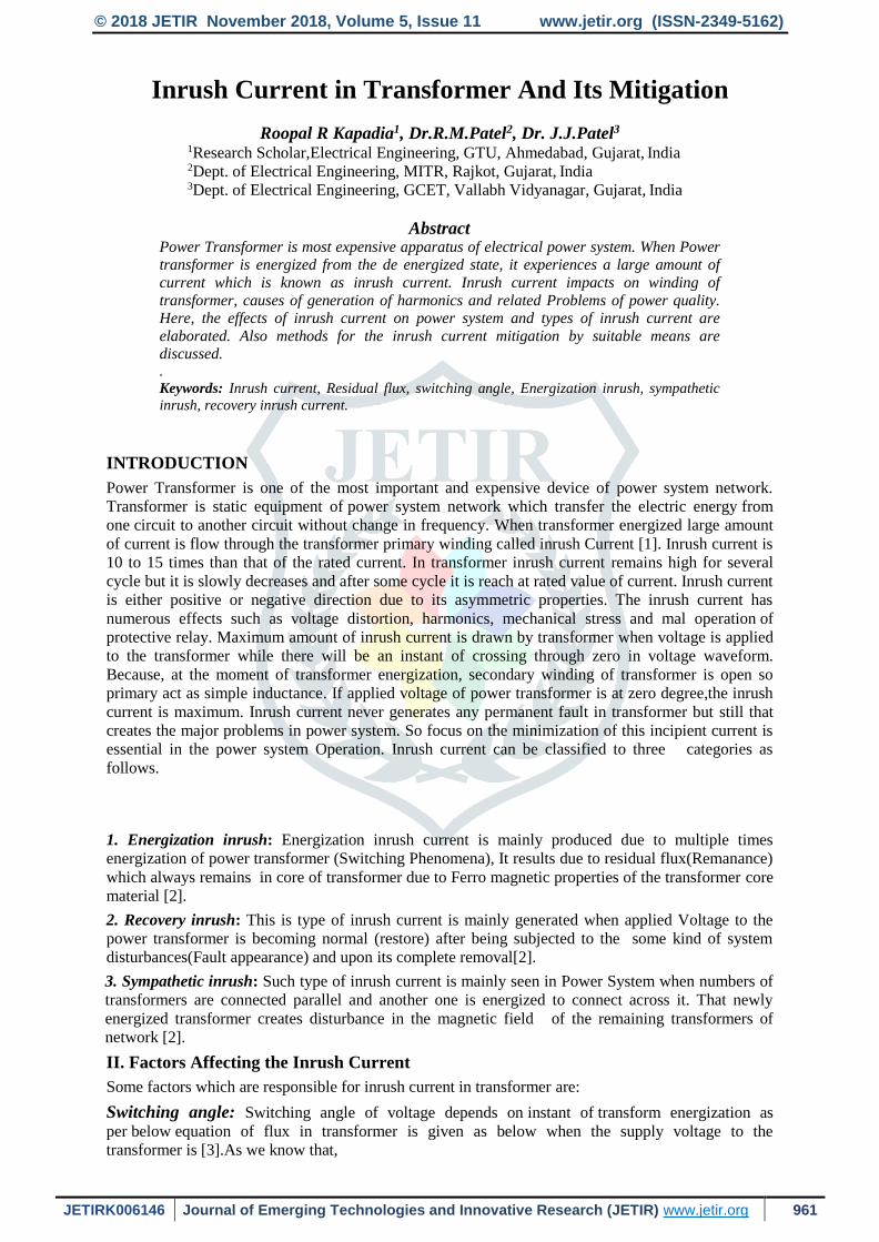
Harmonics: In the transformer inrush current, second order harmonics are predominant due to its
asymmetric properties of material. The key reason is that when inrush current start it pulsates in any
of the positive or negative direction and instead of full wave that will become half wave where
frequency is considered as100 Hz.(i.e. for supply of 50Hz frequency)[6].
Fig. 5 Harmonics contents in Inrush Current
Table III. Contents of Harmonics in transformer Inrush current.
Order of
Harmonic
Amplitude
(in%)
DC 50 to 70%
2nd 63 to 80%
3rd 30 to 50%
4th 5 to 6%
5th 4 to 5%
6th 3 to 3.8%
7th 2 to 2.5%
Stress on transformer winding: During inrush current phenomena in transformer, two types of main
forces acting on the transformer winding as per the Flemings law.
1. Radial force: Radial force occurs during inrush current tries to increase the diameter of winding
2. Axial force: Axial force occurs during inrush current produces thrusts on the winding towards
ground which changes the sizes and able to damage the transformer winding [9] [10].
Malfunction of protective relay: At the time of transformer energization, its draw inrush current at the
amount of 10 to 15 times higher current than that of the rated current, so it makes the malfunctioning
of relays, circuit breakers and send the signal to operates for tripping which is undesirable as this is
temporary phenomena pertains not more than 2 to 3 cycles [11].
IV. Methods to mitigate the inrush current
Asymmetrical winding design: Such type of method used in designing transformer to minimize the
inrush current by the use of asymmetrical winding. This method is totally different from old methods
where equal stress occurred. The inrush current is reduced by increasing the inrush equivalent
inductance by varying the proportion of internal coat to external coat in coil winding in transformer
design. In transformer, the inrush equivalent inductance and leakage inductance were treated and
analyzed as the essential parameters. [12].

© 2018 JETIR November 2018, Volume 5, Issue 11 www.jetir.org (ISSN-2349-5162)
JETIRK006146 Journal of Emerging Technologies and Innovative Research (JETIR) www.jetir.org 965
By using series compensator: In this method we can use of an inverter-based series compensator
which comprised of series transformer and single-phase inverter. Such strategy is easier to practice
because in this no information of the transformer parameters, power-on angle of circuit breaker and
measurement of residual flux are needed. In this method, the compensating current injection on the
secondary winding of the transformer is done by the series compensator. The polarity of the
compensating current applied by the series compensator is opposite than that of the inrush current
generated by the power transformer [13]. Value of residual flux is shown below.
Fig. 6 Inrush current peak for various residual flux without series compensator [13]
Fig.5 and 6 show the residual flux in transformer primary winding without compensator and with
compensator respectively.
Sequential phase energization method: In this type of method the energization of all three phases of
transformer are done at proper instant by the use of suitable means. In this case energization of each
phase of transformer is done in sequential way (at calculated desired) so as to reduce the inrush
current. If say for 50 Hz frequency, the suitable instant of energization in the transformer can be
calculated as mentioned. For 50 Hz power supply voltage we can say that there are 50 cycles in one
second. so 20msec is the time lapsed for one cycle.
Fig. 7 Inrush current peak for various residual fluxes with series compensator [12]
By that, 10 msec. is needed to complete the half cycle (180° degree), 5 msec. is for quarter cycle (90°
degree). In given transformer say the closing sequence of circuit breakers (of all 3 phases)is RYB,
then the closing instant for the phase R voltage for the 90° is after 5 msec. assuming that we supply
breaker of phase R will operated first as per the given sequence, Now the Next one breaker of phase Y
is connected at 120° apart from phase R that means to have realization of 90° + 120° =210 ,
equivalent time needed for lapse of an angle 0° to 210° is 11.666666 msec. similarly after energization
of phase Y ,phase B is energized at 120° from phase Y as equal to 210°+120°=330° which in turn
need the time delay duration for 0° to 330° as 18.3333333 msec. [14] [15].
© 2018 JETIR November 2018, Volume 5, Issue 11 www.jetir.org (ISSN-2349-5162)
JETIRK006146 Journal of Emerging Technologies and Innovative Research (JETIR) www.jetir.org 966
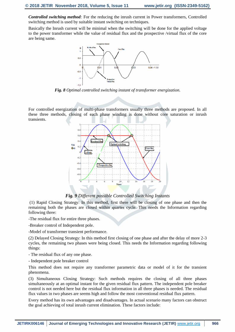
Controlled switching method: For the reducing the inrush current in Power transformers, Controlled
switching method is used by suitable instant switching on techniques.
Basically the Inrush current will be minimal when the switching will be done for the applied voltage
to the power transformer while the value of residual flux and the prospective /virtual flux of the core
are being same.
Fig. 8 Optimal controlled switching instant of transformer energization.
For controlled energization of multi-phase transformers usually three methods are proposed. In all
these three methods, closing of each phase winding is done without core saturation or inrush
transients.
Fig. 9 Different possible Controlled Switching Instants
(1) Rapid Closing Strategy: In this method, first there will be closing of one phase and then the
remaining both the phases are closed within quarter cycle. This needs the Information regarding
following three:
-The residual flux for entire three phases.
-Breaker control of Independent pole.
-Model of transformer transient performance.
(2) Delayed Closing Strategy: In this method first closing of one phase and after the delay of more 2-3
cycles, the remaining two phases were being closed. This needs the Information regarding following
things:
- The residual flux of any one phase.
- Independent pole breaker control
This method does not require any transformer parametric data or model of it for the transient
phenomena.
(3) Simultaneous Closing Strategy: Such methods requires the closing of all three phases
simultaneously at an optimal instant for the given residual flux pattern. The independent pole breaker
control is not needed here but the residual flux information in all three phases is needed. The residual
flux values in two phases are seems high and follow the most conventional residual flux pattern.
Every method has its own advantages and disadvantages. In actual scenario many factors can obstruct
the goal achieving of total inrush current elimination. These factors include:

© 2018 JETIR November 2018, Volume 5, Issue 11 www.jetir.org (ISSN-2349-5162)
JETIRK006146 Journal of Emerging Technologies and Innovative Research (JETIR) www.jetir.org 967
1. Irregularity in circuit breaker.
2. Time for mechanical closing.
3. Circuit breaker prestrike Effect.
4. Erroneous residual flux measurement.
5. Winding configuration or Transformer core which stop a best possible solution.
6. Irregularity in mechanical closing times: All circuit breakers have some statistical abnormality
in their time of mechanical closing varying from operation to operation. For a breaker designed
for controlled closing, approximate closing time deviations are less than ± 1 ms [16 [17].
Virtual air gap: This strategy depends upon the applications of virtual air gap which equivalent
thickness differs in function of controllable constraints changed to the configuration of magnetic
circuit and the related control system. The AGW (air gap width)current is either set to a specific value
using an external source, or a current sensor, in the main magnetization winding of the magnetic
circuit [18]. Physically, the effects are observed on the experimental system are very similar to those
of devices with a real built-in-air-gap. The originality of the method is in the control of the air gap
thickness by the AGW current. Using an AGW always requires a magnetic circuit which is
magnetized through a main winding.
Pre fluxing method: In this method, the residual flux will be set to its maximum value and after that
use of pre-fluxing device to remove the residual flux in the transformer. Pre-fluxing method is
performed into two parts:
Step-1) when transformer is totally de-energized, residual flux is set to possible of its optimum value.
Step-2) In second phase controlling of the circuit breaker for the energization of the single phase
transformer at any of one angle of 210° or positive residual flux, or 330° for negative residual flux.
Use three pole circuit breaker is there for the three phase circuit breaker
Fig. 10 Pre-fluxing device
The pre-fluxing device is shown in above figure. That is made of a diode, capacitor, a fuse, and a
switch. Pre fluxing device is employed only when the transformer is isolated from power system and
connected across one of the winding of transformer. Charging of the pre-fluxing device will be done
before transformer energization. Charging circuit disconnected from the device when the charging is
finished, and transformer is connected to pre fluxing device through isolator 19] [20] [21].
By using ultra low frequency power source: In this strategy, reduction of the flux in core by
supplying voltage to the tertiary winding before the actual energization of transformer primary
winding. Low voltages of power frequency and high frequency are applied to tertiary winding of
transformer to minimize the inrush current of transformer. It is equivalent of injecting a very low
voltage(power frequency signal) into the tertiary winding so as prevent the flux of core entering in the
region of deep saturation [22]. The minimization of residual flux of transformer is done by the help of
a low power ultra-low frequency voltage source. Here the source is connected between any two out of
three terminals points of the head of the feeder line. De magnetizing device is contains of power
electronic switch, low voltage constant DC source and simple controller [23].
Bidirectional impedance type transformer inrush current limiter: When a transformer is energized,
the BITICL instantaneously and automatically connects into the circuit to prevent the inrush current
without using any control circuit. After reducing the transformer inrush current, the BITICL is
bypassed automatically and the transformer seems to connect directly to the source voltage. Thus,
when the transformer is loaded, almost no deformation in the steady-state load voltage and current
waveforms due to the voltage-compensation effect in the limiter [24].
V. Conclusion: Different method for reduce the inrush current in transformer; a most suitable method
is pre- fluxing method. In pre fluxing method calculation of residual flux is not necessary. But in

© 2018 JETIR November 2018, Volume 5, Issue 11 www.jetir.org (ISSN-2349-5162)
JETIRK006146 Journal of Emerging Technologies and Innovative Research (JETIR) www.jetir.org 968
controlled switching method it required the calculation of residual flux. Asymmetrical winding design
is considered at designing of transformer. It’s not useful for that transformer which already active in
power system network. Pre fluxing device is used for those transformer which are executed in system.
REFERENCES
[1] S.V.kulkarni, S.A.kharpade. Transformer engineering:design and practice, MARCEL
DEKKER INC;2004.
[2] Vaddeboina, V, Taylor, G & Proudfoot C:Switching large transformers on weak transmission
networks – A real time case study, Universities power engineering conference,47th
international conference,IEEE, London. September 2012; 4-7:1-6.
[3] Y.G. paithankar and S.R. bhide. fundamental of power system protection PHI Pvt. Ltd.2011.
[4] Blume, LF, Camilli, G, Farnham, SB & Peterson, HA: Transformer Magnetizing Inrush
Currents and In-fluence on System Operation,’ AIEE Transactions. 1994;Vol. 63, No. 6: pp.
366-375.
[5] Goran Petrović, Tomislav Kilić, Stanko Milun :Remanent flux measurement and optimal
energization instant determination of power transformer..XVII IMEKO World Congress
Metrology in the 3rd Millennium, Dubrovnik, Croatia,,June 22 −27, 2003.
[6] Seo, HC & Kim, CH :The analysis of power quality effects from the transformer inrush current.
A case study of the Jeju power station, Koria”, Power and energy society general meeting-
conversion and delivery of electrical energy in the 21st century 2008,IEEE, PA Pittsburgh. ,
2008: 20-24 July:pp. 1-6.
[7] Lin, C.E., Cheng, C.L., Huang, C.L., and Yeh, J.C.: Investigation of magnetizing inrush current
in transformers- Part I: Numerical simulation.IEEE Transactions on Power Delivery. January
1993;Vol. 8, No. 1:pp. 246–254.
[8] Al-Khalifah A. K. and Al-Saadany E. F. :Investigation of magnetizing inrush current in a
single-phase transformer. IEEE Conference on Power Engineering, July 26-28, 2006;pp. 165-
171.
[9] Neves, W, Fernandes, D, Baltar, F, Rosentino, A, Saraiva, E, Delaiba, A, Guimaraes, R, Lynce,
M & de Oliveira, J 2011:A comparative investigation of electromechanical stress on
transformers caused by inrush and short-circuited currents. International conference on
electrical power quality and utilisation EPQU, Libson,October 2011;17-19.
[10] Faiz, J., Ebrahimi, B.M., Abu-Elhaija, W.Computation of static and dynamic axial and radial
forces on power transformer windings due to inrush and short circuit currents. Applied
Electrical Engineering and Computing Technologies (AEECT)Jordan.2011.
[11] Fahrudin Mekic, Ramsis Girgis, Zoran Gajic, Ed teNyenhuis.Power Transformer
Characteristics and Their Effect on Protective Relays.33rd Western Protective Relay
Conference. October 17-19, 2006.
[12] J. Chhen, T. Liang, C. Cheng, S. Chen, R. Lin and W. Yang.Asymmetrical winding
configuration to reduce inrush current with appropriate short-circuit current in
transformer.IEEE Proc.-Electr. Power Appl. May 2005;Vol.152, No.3.
[13] Juei - Lung Shyu," A Novel Control Strategy to Reduce Transformer Inrush Currents by Series
Compensator ", IEEE PEDS 2005.
[14] F. Ali Asghar and K. P. Basu.Reduction of three phase transformer magnetizing inrush current
by use of point on wave switching .IEEE Student Conference on Research and Development,
Malaysia. Nov. 16-18 2009;pp-368-370.
[15] Hany A. Abdelsalam , Almoataz Y. Abdelaziz. A New Strategy for Selection of Switching
Instant to Reduce Transformer Inrush Current in a Single-phase Grid-connected Photovoltaic
System. Electric Power Components and Systems Taylor & francis, , 13 jun. 2015; vol.43:page
1297-1306.
[16] J. Brunke, K. Frohlich. Elimination of Transformer Inrush Currents by Controlled Switching-
Part I: Theoretical considerations. IEEE Transactions on Power Delivery. April 2001; vol 16
no.2.
© 2018 JETIR November 2018, Volume 5, Issue 11 www.jetir.org (ISSN-2349-5162)
JETIRK006146 Journal of Emerging Technologies and Innovative Research (JETIR) www.jetir.org 969
[17] J. Brunke, and K. Frohlich. Elimination of Transformer Inrush Currents by Controlled
Switching Part II: Application and performance considerations. IEEE Transactions on Power
Delivery. April 2001; vol 16 no.2.
[18] V. Molcrette , J. L. Kotony, J. P. Swan and J. F. Brudny.Reduction of inrush current insingle-
phase transformer using virtual air gap technique. IEEE Trans.Magn.. 1998. vol. 34:pp.1192 -
1194,.
[19] D.I.Taylor, N.Fischer, J. D. Law, and B. K. Johnson.Using Lab-VIEW to measure transformer
residual flux for inrush current reduction.The North Amer. Power Symp., Starkville, MS. Oct. 4–
6, 2009.
[20] Douglas I. Taylor, Joseph D. Law, Brian K. Johnson, and Normann Fischer. Single phase
transformer inrush current reduction using prefluxing. IEEE Transactions On Power Delivery.
January 2012;Vol. 27, No. 1.
[21] Douglos I. Taylor.System apparatus, and method for reducing inrush current in a three phase
transformer.United states patent, patent no. US 8,878,391 B2.date: Nov, 4, 2014.
[22] V. Oiring de Castro Cesar, L-L. Rouve, J-L. Coulomb, F-X. Zgainski, O. Chadebec, and B.
Caillault.Elimination of inrush current using a new prefluxing method. Application to a single-
phase transformer.IEEE. 2014.
[23] B. Kovan, F. de Leon, D. Czarkowski, Z. Zabar, and L. Birenbaum. Mitigation of inrush
currents in network transformers by reducing the residual flux with an ultra-low-frequency
power source. IEEE Trans. Power Del. , Jul. 2011; vol. 26, no. 3: pp. 1563–1570.
[24] D. P. Balachandran, K. R. Sreerama and V. P. Shimnamol. Transformer Inrush Current
Redution by Power Frequency Low Voltage Signal Injection to the Tertiary Winding. IEEE
conf Powertech “07. 2007; pp.1953 -1958.
[25] Hsu-Ting Tsenga, Jiann-Fuh Chenb .Bidirectional impedance-type transformer inrush current
limiter.ELSEVIER.November 2013;Volu me 104: pp. 193-206.