insert grades ca515/ca525 ca5 /ca5 - … ca515... · automotive part (s45c) dnmg150408pq...
TRANSCRIPT

CA5CA51515/CA5/CA52525Insert Grades CA515/CA525
Long tool life and Long tool life and stable machiningstable machining
CVD Coated Grades for Steel Machining
New coating technology for longe
r tool life and stable machining
New coating technology for longe
r tool life and stable machining

CVD coated grades for steel machining
● Longer tool life and more stable machining by improved coating film interface
● Interface strength improved by 40%improved by 40%
● Special carbide substrate with high temperature deformation resistance
High temperature hardnessimproved by 10%improved by 10% ● Suitable for high efficiency machining
● Tool life improved by high-aspect ratio ofα-Al2O3 film
● Prevent adhesion and sudden fracture during steel machining ● Easy to detectused cutting edge even in poor lighting conditions
● More coverage of steel machining by recent introduced PP and PQ chipbreakers
New special carbide substrate
High hardness and toughness α-Al2O3 film
Smooth and even surface with low cutting force
Smart chipbreaker PP / PQ
CA515 CA525 Stable and general-use grade for steel machining
TiN layer
Bonding layer
TiCN layer
Carbide substrate
α-Al2O3 layer
Special carbide substrate
0.25
0.2
0.1
0.15
0.05
00.0 6.0
Cutting time (min)
No
se w
ear (
mm
)
12.0 18.0
Competitor A
Conventional B
CA515
■ Wear resistance comparison SCM435 Vc=300m/min,ap=2.0mm, f=0.3mm/rev,wet
CA525
Conventional C
Competitor D
0 1000 2000 3000 4000 5000 6000 7000
123451234512345
Number of shocks before chipping (times)
■ Fracture resistance comparison SCM440=(with 4 slits) Vc=300m/min,ap=1.5mm, f=0.3mm/rev,wet
PP chipbreaker for fi nishingPP chipbreaker for fi nishing PQ chipbreaker for fi nishing to medium cuttingPQ chipbreaker for fi nishing to medium cutting
High
Stability
Wea
r re
sist
ance
High
NEW
NEW
ConventionalP25 coating
ConventionalP15 coating
Long tool life and stable machiningLong tool life and stable machining
High adhesion of coating film - Ultra fine interface -
Wide Wide applicationapplication
rangerange
High speed and long tool life grades for steel machining
2μm
★1
★2 ★3
★4 ★5 Photograph of insert surface
1
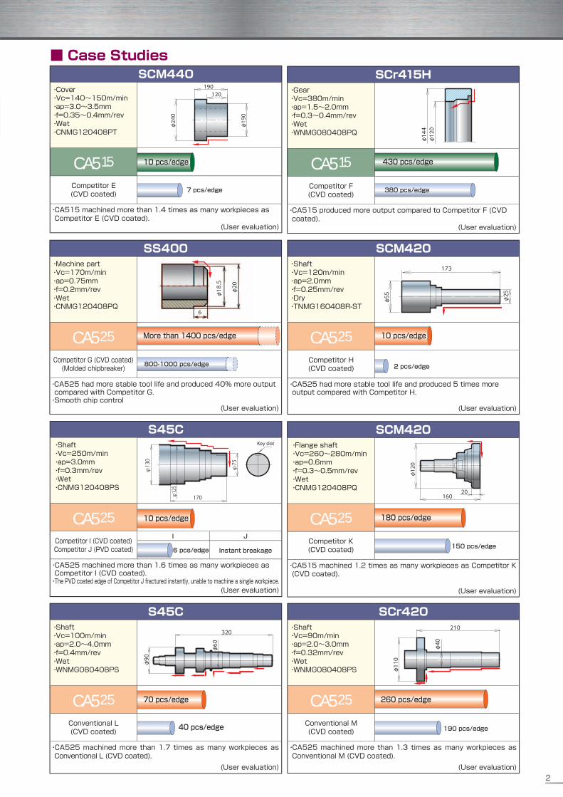
■ Case Studies
JI
10 pcs/edge
7 pcs/edge
430 pcs/edge
380 pcs/edge
10 pcs/edge
2 pcs/edge
More than 1400 pcs/edge
800-1000 pcs/edge
10 pcs/edge
Instant breakage6 pcs/edge 150 pcs/edge
70 pcs/edge
40 pcs/edge 190 pcs/edge
180 pcs/edge
260 pcs/edge
2
SCM420・Shaft・Vc=120m/min・ap=2.0mm・f=0.25mm/rev・Dry・TNMG160408R-ST
CA525
Competitor H(CVD coated)
・CA525 had more stable tool life and produced 5 times more output compared with Competitor H.
(User evaluation)
φ55
173
φ25
SS400・Machine part・Vc=170m/min・ap=0.75mm・f=0.2mm/rev・Wet・CNMG120408PQ
CA525
Competitor G (CVD coated) (Molded chipbreaker)
・CA525 had more stable tool life and produced 40% more output compared with Competitor G.・Smooth chip control (User evaluation)
6
φ20
φ18.5
SCM440・Cover・Vc=140~150m/min・ap=3.0~3.5mm・f=0.35~0.4mm/rev・Wet・CNMG120408PT
CA515
Competitor E(CVD coated)
・CA515 machined more than 1.4 times as many workpieces as Competitor E (CVD coated).
(User evaluation)
φ240
φ190
120190
SCr415H・Gear・Vc=380m/min・ap=1.5~2.0mm・f=0.3~0.4mm/rev・Wet・WNMG080408PQ
CA515
Competitor F(CVD coated)
・CA515 produced more output compared to Competitor F (CVD coated).
(User evaluation)
φ120
φ144
S45C・Shaft・Vc=100m/min・ap=2.0~4.0mm・f=0.4mm/rev・Wet・WNMG080408PS
CA525
Conventional L(CVD coated)
・CA525 machined more than 1.7 times as many workpieces as Conventional L (CVD coated). (User evaluation)
φ90
320
φ60
S45C・Shaft・Vc=250m/min・ap=3.0mm・f=0.3mm/rev・Wet・CNMG120408PS
CA525
Competitor I (CVD coated)Competitor J (PVD coated)
・CA525 machined more than 1.6 times as many workpieces as Competitor I (CVD coated). ・The PVD coated edge of Competitor J fractured instantly, unable to machine a single workpiece. (User evaluation)
φ75
170φ125
φ130
Key slot
SCM420・Flange shaft・Vc=260~280m/min・ap=0.6mm・f=0.3~0.5mm/rev・Wet・CNMG120408PQ
CA525
Competitor K(CVD coated)
・CA515 machined 1.2 times as many workpieces as Competitor K (CVD coated).
(User evaluation)
φ120
16020
SCr420・Shaft・Vc=90m/min・ap=2.0~3.0mm・f=0.32mm/rev・Wet・WNMG080408PS
CA525
Conventional M (CVD coated)
・CA525 machined more than 1.3 times as many workpieces as Conventional M (CVD coated). (User evaluation)
φ110
210
φ40

Automotive part (S45C)
DNMG150408PQ Vc=200m/min ap=0.5-1.2mm f=0.3mm/rev Wet
Competitor O PQ Chipbreaker
Mimimized fracture caused by chip entangle(User evaluation)
■Features● Newly developed Flat Zone (Breaking Area) and 2-step smooth Smart Wall eff ect enables stable chip control in a wide range of application from medium to fi nishing.
● Twin dots on the edge of the grade provide smooth chip control at small ap and higher feedrate in both turning and facing.
● Specially designed Positive Land (CVL) with a well-balanced edge sharpness and toughness.
Prevents chip clogging and reduces cutting force at high feed cuttings.
2 step slight rise for small chip evacuation achieving smooth chipbreaking
Flat Zone(Breaking Area)
・Chip breaking applicable to a wide range of machining.
2-step Smart Wall (2-step rising)Chip control in a wide range of machining, and preventing the dots from being damaged during high feed cutting.
Flat Zone(Breaking Area)
Continuously Variable Land (CVL)Specially designed positive land with well-balanced edge sharpness and toughness.
Finishing - medium
Recent introduced smart chipbreakers PP / PQ Recent introduced smart chipbreakers PP / PQ series with existing PS / PT / PH chipbreakers series with existing PS / PT / PH chipbreakers enable wider coverage of steel machining.enable wider coverage of steel machining.
ap(m
m)
Feed rate(mm/rev)0.40.30.20.1 0.5
2
1
3
4
5(Type C12: Steel)
PSPH
PTPQ
PP
ap(m
m)
Feed rate(mm/rev)0.40.30.20.1 0.5
2
1
3
4
5(Type C12: Steel)
PQ
■ Case Studies (Chip Control Comparison)
■ Case Studies (Chip Control Comparison)
Twin DotsTwin Dots
For finishing
■Features● 3-step Smart Dot Structure is applicable to a wide range of feed ratesin steel fi nishing.
● Smooth Taper Cutting Edge reduces cutting force.
1st DotSmall ap and low feed rate
2nd DotGeneral use
3rd DotLarge ap and high
feed rate
Solution for poor chip control in small ap or high feed cuttings.
3-step Smart Dot StructureThe 3 diff erent dots provide smooth chip evacuation in a wide range of feed rate.
Smooth Taper Cutting EdgeReduced Cutting resistance
ap(m
m)
Feed rate(mm/rev)0.40.30.20.1 0.5
2
1
3
4
5(Type C12: Steel)
PP
NEW
NEW
Automotive part (SCM420)
CNMG120408PPVc=350m/min ap=0.3mm f=0.3mm/rev Wet
Competitor N PP Chipbreaker
Reduced chip entangle and stable cutting.(User evaluation)
3

Medium - roughing
Roughing
Medium - roughing (high feed)
■Features● High stability and improved fracture resistance
■Features● High feed chipbreaker with land support structure for better stability and strengthen the edge.
■Features● Suitable for heavy interrupted cutting and for workpiece with scale due to strong cutting edge.
● Smooth chip control by wide and shallow chipbreaker design.
● A positive land on the edge of the insert prevents crater wear.
ap(m
m)
Feed rate(mm/rev)0.80.60.40.2 1.0
4
2
6
8
10(Type C12: Steel)
PH
ap(m
m)
Feed rate(mm/rev)0.40.30.20.1 0.5
2
1
3
4
5(Type C12: Steel)
PTap
(mm
)
Feed rate(mm/rev)0.40.30.20.1 0.5
2
1
3
4
5(Type C12: Steel)
PS
Dot design suitable for light to middle roughing.
Wide contact surface design for better stability.
Prevents crater wear
Insert edge positive landPrevents chip clogging at high feed cutting
Wide land / Shallow chipbreaker design
High strength
Wide land design
d highat
A wide and shallow chipbreaker allows smooth chips evacuate at chip breaking.
sheet
PT Chipbreaker
no g
ap
Land support structure
Land design with well balanced of sharpness and durability.
Wide Contact Surface prevents micro-Wide Contact Surface prevents micro-chipping caused by insert's micro-vibration chipping caused by insert's micro-vibration during machining.during machining.
4
Shape Description
Dimensions (mm) CVD Coated
I.C. Thickness Hole Corner R(rε)
CA515
CA525
Finishing,with wiper edge
CNMG 120404WP
120408WP12.70 4.76 5.16
0.4
0.8
●
●
●
●
Finishing - medium, with wiper edge
CNMG
120404WQ
120408WQ
120412WQ
12.70 4.76 5.16
0.4
0.8
1.2
●
●
●
●
●
●
Finishing
CNMG 120402PP120404PP120408PP120412PP
12.70 4.76 5.16
0.40.81.21.6
●●●●
●●●●
Finishing
CNMG
120402GP
120404GP
120408GP
12.70 4.76 5.16
0.2
0.4
0.8
●
●
●
●
●
●
Finishing - medium
CNMG
120404PQ
120408PQ
120412PQ
12.70 4.76 5.16
0.4
0.8
1.2
●
●
●
●
●
●
Finishing - medium
CNMG 090404HQ090408HQ
9.525 4.76 3.81 0.40.8
●●
●●
CNMG
120404HQ120408HQ120412HQ
12.70 4.76 5.160.40.81.2
●●●
●●●
Finishing - medium, up facing
CNMG
120404CQ120408CQ120412CQ
12.70 4.76 5.160.40.81.2
●●●
●●●
CNMG 160608CQ160612CQ
15.875 6.35 6.35 0.81.2
●●
●●
Finishing - medium, up facing
CNMG 120408CJ120412CJ
12.70 4.76 5.16 0.81.2
●●
●●
CNMG 160612CJ160616CJ
15.875 6.35 6.35 1.21.6
●●
●●
Medium - roughing
CNMG 090404GS090408GS
9.525 4.76 3.81 0.40.8
●●
●●
CNMG
120404GS120408GS120412GS
12.70 4.76 5.160.40.81.2
●●●
●●●
Medium - roughing
CNMG
120404PS120408PS120412PS120416PS
12.70 4.76 5.16
0.40.81.21.6
●●●●
●●●●
CNMG 160612PS160616PS
15.875 6.35 6.35 1.21.6
●●
●●
●: Standard Stock
Shape Description
Dimensions (mm) CVD Coated
I.C. Thickness Hole Corner R(rε)
CA515
CA525
Medium - roughing, high feed
CNMG 120408PT120412PT
12.70 4.76 5.16 0.81.2
●●
●●
CNMG
160608PT160612PT160616PT
15.875 6.35 6.350.81.21.6
●●●
●●●
Medium - roughing, high feed
CNMG 120408GT
120412GT12.70 4.76 5.16
0.8
1.2
●
●
●
●
Roughing
CNMG
120404120408120412
12.70 4.76 5.160.40.81.2
●●●
●●●
CNMG 160608160612 15.875 6.35 6.35 0.8
1.2●●
CNMG 190612190616 19.05 6.35 7.94 1.2
1.6●●
●●
Roughing
CNMG 120408PH120412PH120416PH
12.70 4.76 5.160.81.21.6
●●●
●●●
CNMG 160608PH160612PH160616PH
15.875 6.35 6.350.81.21.6
●●●
●●●
CNMG 190608PH190612PH190616PH190624PH
19.05 6.35 7.940.81.21.62.4
●●●●
●●●●
Single sided roughing, high feed
CNMM 120408PX120412PX120416PX
12.70 4.76 5.160.81.21.6
●●
●●●
CNMM 160608PX160612PX160616PX
15.875 6.35 6.350.81.21.6
●●●
●●●
CNMM 190608PX190612PX190616PX190624PX
19.05 6.35 7.940.81.21.62.4
●●
●●●●
Low carbon steel, fi nishing
CNMG 120404XP
120408XP12.70 4.76 5.16
0.4
0.8
●
●
●
●
Low carbon steel, medium cutting
CNMG 120404XQ
120408XQ12.70 4.76 5.16
0.4
0.8
●
●
●
●
Low carbon steel, roughing
CNMG 120408XS 12.70 4.76 5.16 0.8 ● ●
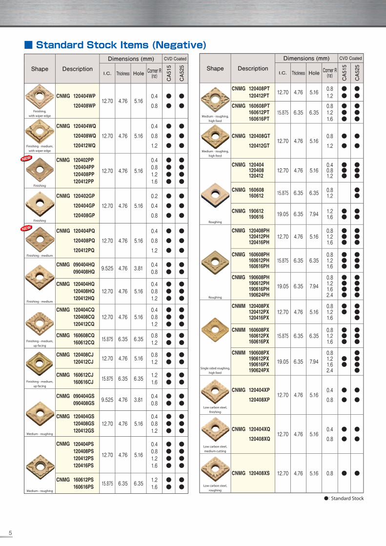
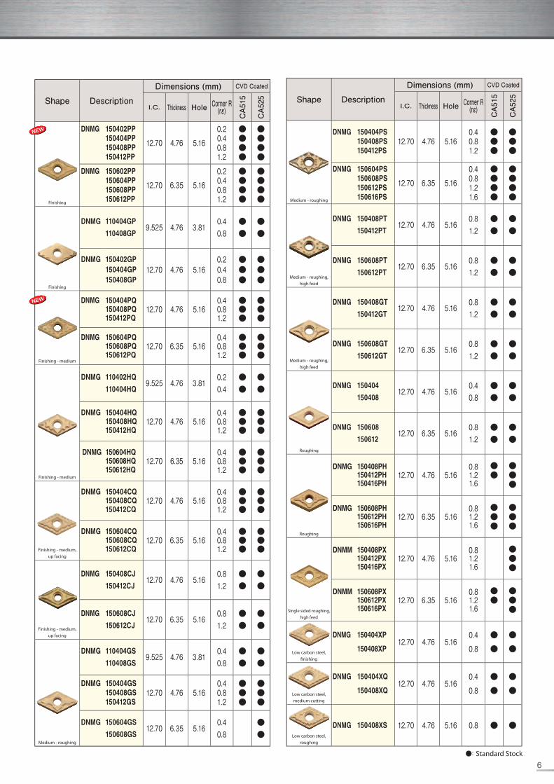
■ Standard Stock Items (Negative)
NEW
NEW
5
●: Standard Stock
Shape Description
Dimensions (mm) CVD Coated
I.C. Thickness Hole Corner R(rε)
CA515
CA525
Finishing
DNMG 150402PP150404PP150408PP150412PP
12.70 4.76 5.16
0.20.40.81.2
●●●●
●●●●
DNMG 150602PP150604PP150608PP150612PP
12.70 6.35 5.16
0.20.40.81.2
●●●●
●●●●
Finishing
DNMG 110404GP
110408GP9.525 4.76 3.81
0.40.8
●●
●●
DNMG 150402GP150404GP150408GP
12.70 4.76 5.160.20.40.8
●●●
●●●
Finishing - medium
DNMG 150404PQ150408PQ150412PQ
12.70 4.76 5.160.40.81.2
●●●
●●●
DNMG 150604PQ150608PQ150612PQ
12.70 6.35 5.160.40.81.2
●●●
●●●
Finishing - medium
DNMG 110402HQ
110404HQ9.525 4.76 3.81
0.20.4
●●
●●
DNMG 150404HQ150408HQ150412HQ
12.70 4.76 5.160.40.81.2
●●●
●●●
DNMG 150604HQ150608HQ150612HQ
12.70 6.35 5.160.40.81.2
●●●
●●●
DNMG 150404CQ150408CQ150412CQ
12.70 4.76 5.160.40.81.2
●●●
●●●
DNMG 150604CQ150608CQ150612CQ
12.70 6.35 5.160.40.81.2
●●●
●●●Finishing - medium,
up facing
Finishing - medium, up facing
DNMG 150408CJ
150412CJ12.70 4.76 5.16
0.81.2
●●
●●
DNMG 150608CJ
150612CJ12.70 6.35 5.16
0.81.2
●●
●●
Medium - roughing
DNMG 110404GS
110408GS9.525 4.76 3.81
0.40.8
●●
●●
DNMG 150404GS150408GS150412GS
12.70 4.76 5.160.40.81.2
●●●
●●●
DNMG 150604GS
150608GS12.70 6.35 5.16
0.40.8
●●
Shape Description
Dimensions (mm) CVD Coated
I.C. Thickness Hole Corner R(rε)
CA515
CA525
DNMG 150404PS150408PS150412PS
12.70 4.76 5.160.40.81.2
●●●
●●●
DNMG 150604PS150608PS150612PS150616PS
12.70 6.35 5.16
0.40.81.21.6
●●●●
●●●●Medium - roughing
DNMG 150408PT
150412PT12.70 4.76 5.16
0.81.2
●●
●●
DNMG 150608PT
150612PT12.70 6.35 5.16
0.81.2
●●
●●
Medium - roughing, high feed
DNMG 150408GT
150412GT12.70 4.76 5.16
0.81.2
●●
●●
DNMG 150608GT
150612GT12.70 6.35 5.16
0.81.2
●●
●●
Medium - roughing, high feed
Roughing
DNMG 150404
15040812.70 4.76 5.16
0.40.8
●●
●●
DNMG 150608
15061212.70 6.35 5.16
0.81.2
●●
●●
Roughing
DNMG 150408PH150412PH150416PH
12.70 4.76 5.160.81.21.6
●●
●●●
DNMG 150608PH150612PH150616PH
12.70 6.35 5.160.81.21.6
●●●
●●●
Single sided roughing, high feed
DNMM 150408PX150412PX150416PX
12.70 4.76 5.160.81.21.6
●●●
DNMM 150608PX150612PX150616PX
12.70 6.35 5.160.81.21.6
●●
●●●
Low carbon steel, fi nishing
DNMG 150404XP
150408XP12.70 4.76 5.16
0.4
0.8
●
●
●
●
Low carbon steel, medium cutting
DNMG 150404XQ
150408XQ12.70 4.76 5.16
0.4
0.8
●
●
●
●
Low carbon steel, roughing
DNMG 150408XS 12.70 4.76 5.16 0.8 ● ●
NEW
NEW
6

Shape Description
Dimensions (mm) CVD Coated
I.C. Thickness Hole Corner R(rε)
CA515
CA525
Medium - roughing
RNMG 090300 9.525 3.18 3.81 - ● ●
RNMG 120400 12.70 4.76 5.16 - ● ●
RNMG 150600 15.875 6.35 6.35 - ●
Finishing - medium
SNMG 120404PQ120408PQ120412PQ
12.70 4.76 5.160.40.81.2
●●●
●●●
Finishing - medium
SNMG 120404HQ120408HQ120412HQ
12.70 4.76 5.160.40.81.2
●●●
●●●
Medium - roughing
SNMG 120408PS120412PS120416PS
12.70 4.76 5.160.81.21.6
●●●
●●●
Medium - roughing, high feed
SNMG 120408PT
120412PT12.70 4.76 5.16
0.8
1.2
●
●
●
●
Roughing
SNMG 090304090308 9.525 3.18 3.81 0.4
0.8●●
SNMG 120408
120412
12041612.70 4.76 5.16
0.81.21.6
●●
●●●
Roughing
SNMG 120408PH120412PH120416PH
12.70 4.76 5.160.81.21.6
●●●
●●●
SNMG 150612PH150616PH 15.875 6.35 6.35 1.2
1.6●●
●●
SNMG 190612PH190616PH 19.05 6.35 7.94 1.2
1.6●●
Single sided roughing, high feed
SNMM 120408PX120412PX120416PX
12.70 4.76 5.160.81.21.6
●●
●●●
SNMM 150612PX150616PX 15.875 6.35 6.35 1.2
1.6●●
SNMM 190612PX190616PX190624PX
19.05 6.35 7.941.21.62.4
●●
●●●
Low carbon steel, fi nishing
SNMG 120408XP 12.70 4.76 5.16 0.8 ● ●
Low carbon steel, medium cutting
SNMG 120408XQ 12.70 4.76 5.16 0.8 ● ●
Shape Description
Dimensions (mm) CVD Coated
I.C. Thickness Hole Corner R(rε)
CA515
CA525
Low carbon steel, roughing
SNMG 120408XS 12.70 4.76 5.16 0.8 ● ●
Finishing
TNMG 160402PP160404PP160408PP160412PP
9.525 4.76 3.81
0.20.40.81.2
●●●●
●●●●
Finishing
TNMG 160402GP160404GP160408GP
9.525 4.76 3.810.20.40.8
●●●
●●●
Finishing - medium
TNMG 160404PQ160408PQ160412PQ
9.525 4.76 3.810.20.40.8
●●●
●●●
TNMG 110404HQ110408HQ
6.35 4.76 2.260.40.8
●●
●●
TNMG 160404HQ160408HQ160412HQ
9.525 4.76 3.810.40.81.2
●●●
●●●
Finishing - medium
TNMG 160404CQ160408CQ160412CQ
9.525 4.76 3.810.40.81.2
●●●
●●●
TNMG 220408CQ220412CQ
12.70 4.76 5.160.81.2
●●
●●Finishing - medium,
up facing
TNMG 110404GS110408GS
6.35 4.76 2.260.40.8
●●
TNMG 160404GS160408GS
9.525 4.76 3.810.40.8
●●
●●
Medium - roughing
TNMG 160404PS160408PS160412PS
9.525 4.76 3.810.40.81.2
●●●
●●●
TNMG 220404PS220408PS220412PS220416PS
12.70 4.76 5.160.40.81.21.6
●●●●
●●●●Medium - roughing
Medium - roughing, high feed
TNMG 160408PT
160412PT9.525 4.76 3.81
0.81.2
●●
●●
Medium - roughing, high feed
TNMG 160408GT
160412GT9.525 4.76 3.81
0.8
1.2
●
●
●
●
●: Standard Stock
■ Standard Stock Items (Negative)
NEW
NEW
NEW
7

Shape Description
Dimensions (mm) CVD Coated
I.C. Thickness Hole Corner R(rε)
CA515
CA525
Roughing
TNMG 160404160408160412
9.525 4.76 3.810.40.81.2
●●●
●●●
TNMG 220408220412 12.70 4.76 5.16 0.8
1.2●●
●●
Roughing
TNMG 160408PH160412PH 9.525 4.76 3.81 0.8
1.2●●
●●
TNMG 220408PH220412PH220416PH
12.70 4.76 5.160.81.21.6
●●●
●●●
Single sided roughing, high feed
TNMM 160408PX160412PX 9.525 4.76 3.81 0.8
1.2●●
TNMM 220408PX220412PX220416PX
12.70 4.76 5.160.81.21.6
●●●
Low carbon steel, fi nishing
TNMG 160404XP
160408XP9.525 4.76 3.81
0.4
0.8
●
●
●
●
Low carbon steel, medium cutting
TNMG 160404XQ
160408XQ9.525 4.76 3.81
0.4
0.8
●
●
●
●
Low carbon steel, roughing
TNMG 160408XS 9.525 4.76 3.81 0.8 ● ●
Medium - roughing
TNMG 160404$-ST
160408$-ST9.525 4.76 3.81
0.4
0.8
●
●
●
●
Finishing
VNMG 160402PP160404PP160408PP160412PP
9.525 4.76 3.81
0.20.40.81.2
●●●●
●●●●
Finishing
VNMG 160402GP160404GP160408GP
9.525 4.76 3.810.20.40.8
●●●
●●●
Finishing - medium
VNMG 160404VF160408VF160412VF
9.525 4.76 3.810.40.81.2
●●●
●●●
Finishing - medium
VNMG 160404PQ160408PQ160412PQ
9.525 4.76 3.810.40.81.2
●●●
●●●
Shape Description
Dimensions (mm) CVD Coated
I.C. Thickness Hole Corner R(rε)
CA515
CA525
Finishing - medium
VNMG 160404HQ160408HQ160412HQ
9.525 4.76 3.810.40.81.2
●●●
●●●
Roughing
VNMG 160404160408 9.525 4.76 3.81 0.4
0.8●●
●●
Finishing,with wiper edge
WNMG 080404WP080408WP 12.70 4.76 5.16 0.4
0.8●●
●●
Finishing - medium, with wiper edge
WNMG 080404WQ080408WQ080412WQ
12.70 4.76 5.160.40.81.2
●●●
●●●
Finishing
WNMG 080402PP080404PP080408PP080412PP
12.70 4.76 5.16
0.20.40.81.2
●●●●
●●●●
Finishing - medium
WNMG 080404PQ080408PQ080412PQ
12.70 4.76 5.160.40.81.2
●●●
●●●
Finishing - medium
WNMG
06T304HQ06T308HQ 9.525 3.97 3.81 0.4
0.8●●
WNMG
060404HQ060408HQ 9.525 4.76 3.81 0.4
0.8●●
●●
WNMG
080404HQ080408HQ080412HQ
12.70 4.76 5.160.40.81.2
●●●
●●●
Finishing - medium, up facing
WNMG
080404CQ080408CQ080412CQ
12.70 4.76 5.160.40.81.2
●●●
●●●
Finishing - medium, up facing
WNMG 080408CJ080412CJ 12.70 4.76 5.16 0.8
1.2●●
●●
Medium - roughing
WNMG 060404GS060408GS 9.525 4.76 3.81 0.4
0.8●●
●●
WNMG 080404GS080408GS080412GS
12.70 4.76 5.160.40.81.2
●●●
●●●
Medium - roughing
WNMG
080404PS080408PS080412PS080416PS
12.70 4.76 5.16
0.40.81.21.6
●●●●
●●●●
●: Standard Stock
NEW
NEW
NEW
NEW
Shape
Right-hand shown
8

Shape Description
Dimensions (mm) CVD Coated
I.C. Thickness Hole Corner R(rε)
CA515
CA525
Medium - roughing, high feed
WNMG 080408PT080412PT 12.70 4.76 5.16 0.8
1.2●●
●●
Medium - roughing, high feed
WNMG
080408GT080412GT 12.70 4.76 5.16 0.8
1.2●●
●●
Roughing
WNMG
080404080408080412
12.70 4.76 5.160.40.81.2
●●●
●●●
Low carbon steel, fi nishing
WNMG 080404XP080408XP 12.70 4.76 5.16 0.4
0.8●●
●●
Low carbon steel, medium cutting
WNMG 080404XQ080408XQ 12.70 4.76 5.16 0.4
0.8●●
●●
Low carbon steel, roughing
WNMG 080408XS 12.70 4.76 5.16 0.8 ● ●
●: Standard Stock
■ Standard Stock Items (Negative)
9
●: Standard Stock
Shape Description
Dimensions (mm) CVD Coated
I.C. Thickness Hole Corner R(rε)
Relief Angle
CA515
CA525
Low carbon steel, fi nishing
DCMT 070204XP 6.35 2.38 2.8 0.4 7° ● ●
DCMT 11T302XP11T304XP11T308XP
9.525 3.97 4.40.20.40.8
7°●●●
●●●
Low carbon steel, fi nishing - medium
DCMT 11T304XQ11T308XQ 9.525 3.97 4.4 0.4
0.8 7° ●●
●●
Medium cutting
RCMX 1003M0 10.0 3.18 3.6 - 7° ● ●
RCMX 1204M0 12.0 4.76 4.2 - 7° ● ●
Finishing - medium
SCMT 09T304HQ09T308HQ 9.525 3.97 4.4 0.4
0.8 7° ●●
●●
Medium cutting
SPMR 090304090308 9.525 3.18 - 0.4
0.8 11° ●●
●●
SPMR 120304120308 12.70 3.18 - 0.4
0.8 11° ●●
●●
Finishing
TBMT 060102DP060104DP 3.97 1.59 2.3 0.2
0.4 5° ●●
●●
Finishing - medium
TCMT 110204HQ110208HQ 6.35 2.38 2.8 0.4
0.8 7° ●●
●●
Finishing
TPMT 090204GP 5.56 2.38 2.8 0.4 11° ● ●
TPMT 110304GP110308GP 6.35 3.18 3.3 0.4
0.8 11° ●●
●●
TPMT 160304GP 9.525 3.18 4.4 0.4 11° ● ●
Finishing - medium
TPMT 090202HQ090204HQ 5.56 2.38 2.8 0.2
0.4 11° ●●
●●
TPMT 110302HQ110304HQ110308HQ
6.35 3.18 3.30.20.40.8
11°●●●
●●●
TPMT 160304HQ160308HQ 9.525 3.18 4.4 0.4
0.8 11° ●●
●●
Shape Description
Dimensions (mm) CVD Coated
I.C. Thickness Hole Corner R(rε)
Relief Angle
CA515
CA525
Finishing - medium
CCMT 060202GK060204GK 6.35 2.38 2.8 0.2
0.4 7° ●●
●●
CCMT 09T302GK09T304GK 9.525 3.97 4.4 0.2
0.4 7° ●●
●●
CCMT 120404GK120408GK120412GK
12.70 4.76 5.50.40.81.2
7°●●●
●●●
Finishing - medium
CCMT 060202HQ060204HQ 6.35 2.38 2.8 0.2
0.4 7° ●●
●●
CCMT 09T302HQ09T304HQ09T308HQ
9.525 3.97 4.40.20.40.8
7°●●●
●●●
Medium cutting
CCMT 09T308 9.525 3.97 4.4 0.8 7° ● ●
Finishing
CPMT 080204GP 7.94 2.38 3.3 0.4 11° ● ●
CPMT 090304GP090308GP 9.525 3.18 4.4 0.4
0.8 11° ●●
●●
Finishing - medium
CPMH 080204HQ080208HQ 7.94 2.38 3.5 0.4
0.8 11° ●●
●●
CPMH 090304HQ090308HQ 9.525 3.18 4.5 0.4
0.8 11° ●●
●●
Medium cutting
CPMH 080204080208 7.94 2.38 3.5 0.4
0.8 11° ●●
●●
CPMH 090304090308 9.525 3.18 4.5 0.4
0.8 11° ●●
●●
Low carbon steel, fi nishing
CPMT 080204XP 7.94 2.38 3.3 0.4 11° ● ●
CPMT 090304XP090308XP 9.525 3.18 4.4 0.4
0.8 11° ●●
●●
Low carbon steel, fi nishing-medium
CPMT 090304XQ090308XQ 9.525 3.18 4.4 0.4
0.8 11° ●●
●●
Finishing
DCMT 070202GP070204GP 6.35 2.38 2.8 0.2
0.4 7° ●●
●●
DCMT 11T304GP11T308GP 9.525 3.97 4.4 0.4
0.8 7° ●●
●●
Finishing - medium
DCMT 070202GK070204GK070208GK
6.35 2.38 2.80.20.40.8
7°●●●
●●●
DCMT 11T302GK11T304GK11T308GK
9.525 3.97 4.40.20.40.8
7°●●●
●●●
Finishing - medium
DCMT 070202HQ070204HQ070208HQ
6.35 2.38 2.80.20.40.8
7°●●●
●●●
DCMT 11T302HQ11T304HQ11T308HQ
9.525 3.97 4.40.20.40.8
7°●●●
●●●
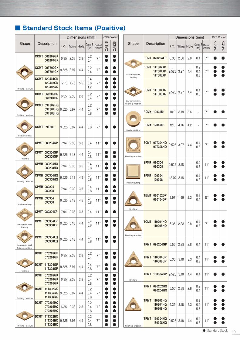
■ Standard Stock Items (Positive)
10

Search "KYOCERA Tools" on App Store & Google play
CP309EN CAT/15T1303TYU
Shape Description
Dimensions (mm) CVD Coated
I.C. Thickness Hole Corner R(rε)
Relief Angle
CA515
CA525
Low carbon steel, fi nishing
TPMT 090204XP 5.56 2.38 2.8 0.4 11° ● ●
TPMT 110304XP110308XP 6.35 3.18 3.3 0.4
0.8 11° ●●
●●
TPMT 160304XP160308XP 9.525 3.18 4.4 0.4
0.8 11° ●●
●●
Low carbon steel, fi nishing - medium
TPMT 110304XQ110308XQ 6.35 3.18 3.3 0.4
0.8 11° ●●
●●
TPMT 160304XQ160308XQ 9.525 3.18 4.4 0.4
0.8 11° ●●
●●
Finishing
TPMR 160304GP 9.525 3.18 - 0.4 11° ● ●
Finishing - medium
TPMR 110304HQ110308HQ 6.35 3.18 - 0.4
0.8 11° ●●
●●
TPMR 160304HQ160308HQ 9.525 3.18 - 0.4
0.8 11° ●●
●●
Medium cutting
TPMR 110304110308 6.35 3.18 - 0.4
0.8 11° ●●
●●
TPMR 160304160308 9.525 3.18 - 0.4
0.8 11° ●●
●●
Finishing
VBMT 110304GP 6.35 3.18 2.8 0.4 5° ● ●
VBMT 160404GP160408GP 9.525 4.76 4.4 0.4
0.8 5° ●●
●●
Shape Description
Dimensions (mm) CVD Coated
I.C. Thickness Hole Corner R(rε)
Relief Angle
CA515
CA525
VBMT 110302VF110304VF110308VF
6.35 3.18 2.80.20.40.8
5°●●●
●●●
VBMT 160402VF160404VF160408VF160412VF
9.525 4.76 4.4
0.20.40.81.2
5°
●●●●
●●●●Finishing
Finishing - medium
VBMT 110304HQ110308HQ 6.35 3.18 2.8 0.4
0.8 5° ●●
●●
VBMT 160404HQ160408HQ160412HQ
9.525 4.76 4.40.40.81.2
5°●●●
●●●
Finishing
VCMT 080202VF080204VF 4.76 2.38 2.3 0.2
0.4 7° ●●
●●
Finishing - medium
VCMT 080202HQ080204HQ 4.76 2.38 2.3 0.2
0.4 7° ●●
●●
Finishing
WBMT 060102$-DP060104$-DP 3.97 1.59 2.3 0.2
0.4 5° LL
LL
WBMT 080202$-DP080204$-DP 4.76 2.38 2.3 0.2
0.4 5° LL
LL
Finishing
WPMT 110204GP 6.35 2.38 2.8 0.4 11° ● ●
WPMT 160304GP 9.525 3.18 4.4 0.4 11° ● ●
Finishing - medium
WPMT 110202HQ110204HQ 6.35 2.38 2.8 0.2
0.4 11° ●●
●●
WPMT 160304HQ160308HQ 9.525 3.18 4.4 0.4
0.8 11° ●●
●●
●: Standard Stock L: L-hand Only
■ Standard Stock Items (Positive)
Shape