inspection instrument for indicators...
TRANSCRIPT

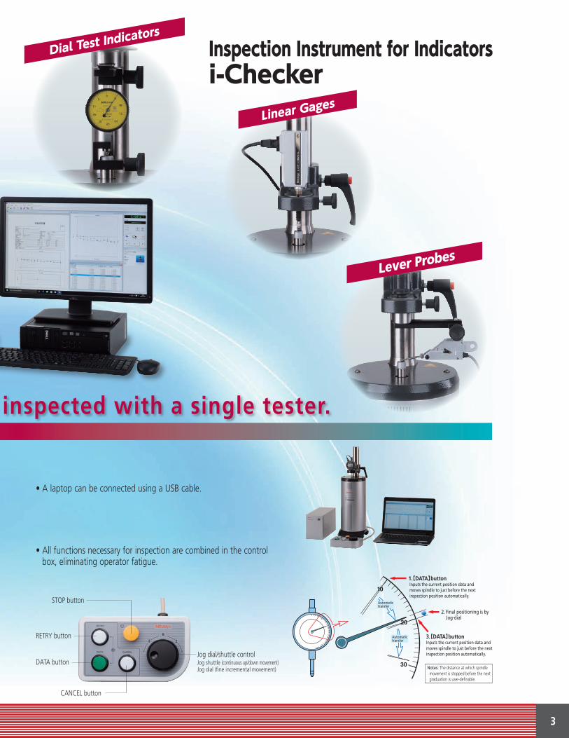
Inspection Instrument for Indicatorsi-Checker
Bulletin No. 2239
SMAL
L TO
OL
INST
RUM
ENTS
AN
D DA
TA M
ANAG
EMEN
T

2
For efficient in-house calibration
Features
Inspection using analog indicator Inspection using digital indicator
Various types of indicators can be inspected with a single tester.
• The latest standard for dial test indicators, ASME and DIN, are applied.
• Operators can customize inspection standards and inspection certifications.
• Inspection can be performed 2.5 times faster compared to the previous model.
• This instrument achieves the highest accuracy in its class (Mitutoyo survey, February 2016) and, therefore, guarantees ultra-reliable inspection results.
• Digital indicators equipped with a data output function are efficiently checked due to spindle positioning at the inspection points and records fully automatic measurement results.
• Analog indicators are inspected in semi-automatic mode with the pointer of the indicator manually adjusted at each measuring point with automatic transfer of inspection results and movement to the next measuring point.
3
STOP button
RETRY button
DATA button
CANCEL button
Jog dial/shuttle controlJog shuttle (continuous up/down movement)Jog dial (fine incremental movement)
Various types of indicators can be inspected with a single tester.
• A laptop can be connected using a USB cable.
• All functions necessary for inspection are combined in the control box, eliminating operator fatigue.
Automatictransfer
Automatictransfer
1.【DATA】button Inputs the current position data and moves spindle to just before the next inspection position automatically.
2. Final positioning is by Jog-dial
3.【DATA】buttonInputs the current position data andmoves spindle to just before the nextinspection position automatically.
Notes: The distance at which spindle movement is stopped before the next graduation is user-definable.
Lever Probes

4
Optional Accessories and Applications
i-Checker mountable bore gages
Applications for Bore Gage Accessory Set
List of components for bore gage accessory set (type C) Order No.02ASU161
Applications for bore gage measurement accessory set (type C)
Application for mounting bore gage accessory set (type C) Order No. 02ASU161
Range (mm)a ø6 - ø18b 50 or belowc 120 or below
(1)
(3)
(4) (5)
(6)(7)(8)(9)
(10)
(11)
(12)
(13)
(2)
(1) Bore gage accessory (2) Stand B(3) V-shaped attachment B(4) Bore gage stopper 5 (5) Anvil (for calibration, M11 female)(6) Anvil (for calibration, M3.5 x 0.35 male) (7) Anvil (for calibration, M3.5 x 0.5 male) (8) Anvil (for calibration, M5 male) (9) Anvil (for calibration, M11 male)
(10) V-shaped attachment C(11) Bore gage stopper 3 (12) i-Checker's special contact point (13) Key wrench
a
c
b

5
Dial test Indicator accessory set (for ø6 stem)*
Applications for Dial Test Indicator Accessory Set
Order No.02ASK000*
Applications for dial test indicator accessory set (for horizontal type)
Applications for dial test indicator accessory set (for vertical type)
* other set sizes available
240100
73
Wooden box
46.5
90
41 48.5
15
27
2559
.5

6
Optional accessoriesAttachments/Stem bushing/Others/Connecting cables Dedicated software (i-Pak specification)
Order No. Item Usage and remarks
Attachment
02ASK000 Test indicator accessory set (for ø6mm stem) For attachment of ø6 stem test indicator
02ASK180 Test indicator accessory set (for ø8mm stem) For attachment of ø8 stem test indicator
02ASK370 Test indicator accessories set (for ø6 stem) Holder to fix ø6 stem to 02ASK180
02ASK380 Test indicator accessories set (for ø8 stem) Holder to fix ø8 stem to 02ASK000
902803 ø6 dovetail grooved stemStem to attach Mu-Checker with knurled clamp ring (lever head) to test indicator accessory set (02ASK000)
902804 ø8 dovetail grooved stemStem to attach Mu-Checker with knurled clamp ring (lever head) to test indicator accessory set (02ASK180)
02ASU161 Bore gage accessory set (type C) Accessory set for holding grip bore gage
Stem bushing
02ASK040 Stem bushing ø6
02ASJ856 Stem bushing ø8
02ASK150 Stem bushing ø8, short For attachment of cartridge head MCHP-341
02ASL150 Stem bushing ø10
02ASK050 Bushing ø9.5 - ø15For attachment of LGB2 fixing nut with stem diameter ø9.5Stem bushing (ø15mm) is required separately.
02ASK060 Stem bushing ø12
02ASK070 Stem bushing ø15
02ASK080 Stem bushing ø20
02ASK710 Stem bushing ø28
02ASK090 Stem bushing ø3/8 in For attachment of indicator with stem diameter ø9.525mm
02ASK130 Wooden box for No. 02ASK130 stem bushings
Storage of 7 stem bushings and 1 bushing (ø9.5 - ø15mm)
Others
937179T Foot switch Used instead of [DATA] button in the operation box.
02ASK730 Observation mirror
Connecting cables
905338 Connecting cable (1m)*1Used for connecting with Digimatic Indicators (ID-C, ID-S, ID-U, and IDU)905409 Connecting cable (2m)*1
936937 Connecting cable (1m)*1(ID-F, IDF, Digimatic power supply unit and between the testers)965014 Connecting cable (2m)*1
937387 Connecting cable (1m)*1Used for connecting with Digimatic Indicators (IDC and IDA)965013 Connecting cable (2m)*1
965275 Digimatic power supply unit*2
Used for the Digimatic Indicators that require external power supply
*1 Use the cable described in the user's manual.*2 Confirm the specification in the user's manual.
• Supported OSWindows10(64bit)• Supported Industrial StandardsISO, JIS, JMAS, ANSI/ASME, DIN, VDI/VDE/DGQ, BS
• Basic inspection functions· Creation of inspection standard conformed to the industrial standard· Creation and editing of original inspection standard by customizing the industrial standard· Inspection of indicator using the inspection standard (inspection for accuracy and repeatability)· Graphical display of measurement result· Creation, editing and printing of simplified inspection certificate
• Function· Retry "measurement positioning"· Re-measurement· Data cancellation· Change of speed for jog shuttle
• Input/Output specifications· Digimatic data connector (rear side of i-Checker main unit)*3
· PC serial-data input port (RS-232C)· Printing of simplified inspection certificates
*3 Automatic measurement requires the indicator's connecting cable.
Supported indicators
• Dial Indicator• Dial Test Indicator• Mitutoyo Hicator• Bore Gage• Digimatic Indicator• Linear Gage• Mu-Checker
* It cannot inspect the indicator with accuracy that is higher than the main unit accuracy of the tester.
* Resolution of Mu-checker is greater than 1μm (e.g. 1μm/5μm/10μm/50μm).

7
Supported Industrial Standards
Specifications
Dimensions
Standard accessories supplied Order No.64PKA148
Order No. Item QTY.02AST250 Tester main unit 102AST780 Controller ICMC-2 102NJA004 i-Pak 2.0 102ZAA010 AC Cable 102AST830 Control box 102ASU001 EXT. Signal Cable 102ASU002 EXT. Motor Cable 1
02ASU003A EXT. USB2.0 Cable 102ASJ856 Stem bushing Φ8mm 102ASK091 Stem bushing Φ9.525mm (3/8 in) 1601614-2 Dust cover 1
99MBD063A User's Manual (English) 1
— Inspection certificate, Certification of calibration and Traceability chart (English) 1
Dial Indicator Dial Test Indicator Hicator Bore Gage Digimatic Indicator Linear Gage Mu-Checker
ANSI/ASME B89.1.10M-2001 B89.1.10M-1987
B89.1.10M-2001 B89.1.10M-1987 — — B89.1.10M-2001 — —
ISO 463-2006R463-1965 9493-2010 — — — — —
JISB7503-2011B7503-1997B7503-1992
B7533-2015B7533-1990 B7519-1994 B7515-1982 — — B7536-1982
JMAS2001-19982001-19942003-1994
— — 5009-1988 — — 5003-1962
DIN 878-2006878-1983 2270-1985 879-1983 — — — —
VDI/VDE/DGQ 2618Blatt11-1991
2618Blatt11.3-2002
2618Blatt20-1991
2618Blatt21-1991 — — — 2618
Blatt26-1991
BS 907-1965 2795-1981 — — — — —Mitutoyo Standard — — — — ✔ ✔ —
Order No. 64PKA148†
Measuring Range 100mm / 4"Resolution 0.01μm / .1μin
Accuracy(20°C)
vertical position (0.1+0.4L/100) μm L = Arbitrary length (mm)lateral position (0.15+0.6L/100) μm L = Arbitrary length (mm)
Feed speed Maximum 10mm/s
Drive method Motor drive, semi-automatic, fully automatic (Fully automatic only for indicators with SPC data output)
Measuring Unit Separate linear encoderThermal expansion coefficient ofmeasurement mode
1.5×10 -6 / K
Measurement method
Semi-automatic measurementFully automatic measurement
(only when using an indicators equipped with data output function) *1*2
Mass 20kgOperating temperature range 20°C±0.5°C
164 ø200
370.
518
9ø160
559.
5
73 79.5
384.
8St
roke
100
ø8mm / ø9.525mm (3/8 in), Standard accessory
Unit: mm
*1 Automatic measurement requires the indicator’s connecting cable.
*2 The indicator measured via RS-232C has the capability to receive data from the main unit and output the counter value.
† Recommended PC package: 64PKA149D

Coordinate Measuring Machines
Sensor Systems
Vision Measuring Systems
Test Equipmentand Seismometers
Form Measurement
Digital Scale and DRO Systems
Optical Measuring
Small Tool Instrumentsand Date Management
Whatever your challenges are, Mitutoyo supports you from start to finish.
Mitutoyo is not only a manufacturer of top-quality measuring products but one that also offers qualified support for the lifetime of the equipment, backed by comprehensive services that ensure your staff can make the very best use of the investment.
Apart from the basics of calibration and repair, Mitutoyo offers product and metrology training, as well as IT support for the sophisticated software used in modern measuring technology. We can also design, build, test and deliver measuring solutions and even, if deemed cost-effective, take your critical measurement challenges in-house on a sub-contract basis.
Mitutoyo America Corporationwww.mitutoyo.comOne Number to Serve You Better1-888-MITUTOYO (1-888-648-8869)
M3 Solution Centers:Aurora, Illinois (Headquarters)Boston, MassachusettsCharlotte, North CarolinaCincinnati, OhioDetroit, MichiganLos Angeles, CaliforniaBirmingham, AlabamaSeattle, WashingtonHouston, Texas
500 0317-02 • Printed in USA • May 2017
© 2
017
Mitu
toyo
Am
erica
Cor
pora
tion
Find additional product literature and our product catalog
www.mitutoyo.com
Note: All information regarding our products, and in particular the illustrations, drawings, dimensional and performance data contained in this printed matter as well as other technical data are to be regarded as approximate average values. We therefore reserve the right to make changes to the corresponding designs. The stated standards, similar technical regulations, descriptions and illustrations of the products were valid at the time of printing. In addition, the latest applicable version of our General Trading Conditions will apply. Only quotations submitted by ourselves may be regarded as definitive. Specifications are subject to change without notice.
Mitutoyo products are subject to US Export Administration Regulations (EAR). Re-export or relocation of our products may require prior approval by an appropriate governing authority.
Trademarks and RegistrationsDesignations used by companies to distinguish their products are often claimed as trademarks. In all instances where Mitutoyo America Corporation is aware of a claim, the product names appear in initial capital or all capital letters. The appropriate companies should be contacted for more complete trademark and registration information.