instability control by premixed pilot flames
TRANSCRIPT
1
ttbnidgiscppgsa
s
caos
2P9
J
Downloaded Fr
Peter Albrecht1
e-mail: [email protected]
Stefanie Badee-mail: [email protected]
Arnaud Lacarellee-mail: [email protected]
Christian Oliver PaschereitProfessor
e-mail: [email protected]
Hermann-Foettinger Institute (ISTA),Technical University of Berlin,
D-10623 Berlin, Germany
Ephraim GutmarkDistinguished Professor
Department of Aerospace Engineering andEngineering Mechanics,University of Cincinnati,
Cincinnati, OH 45221-0070e-mail: [email protected]
Instability Control by PremixedPilot FlamesPremixed flames of swirl-stabilized combustors (displaced half-cone) are susceptible tothermo-acoustic instabilities, which should be avoided under all operating conditions inorder to guarantee a long service life for both stationary and aircraft gas turbines. Thesource of this unstable flame behavior can be found in a transition of the premix flamestructure between two stationary conditions that can be easily excited by fuel fluctuations,coherent structures within the flow, and other mechanisms. Pilot flames can alleviate thisissue either by improving the dynamic stability directly or by sustaining the main com-bustion process at operating points where instabilities are unlikely. In the present study,the impact of two different premixed pilot injections on the combustion stability is inves-tigated. One of the pilot injector (pilot flame injector) was located upstream of therecirculation zone at the apex of the burner. The second one was a pilot ring placed at theburner outlet on the dump plane. A noticeable feature of the pilot injector was that anignition device allowed for creating pilot premixed flames. The present investigationshowed that these premixed pilot flames were able to suppress instabilities over a widerfuel/air ratio range than the conventional premixed pilot injection alone. Furthermore, itwas possible to prevent instabilities and maintain the flame burning near the lean blow-out when a percentage of the fuel was premixed with air and injected through the pilotring. NOx emissions were significantly reduced. �DOI: 10.1115/1.3019293�
IntroductionThe prevention and suppression of unstable combustion condi-
ions in contemporary combustion chambers have to be guaran-eed in all cases as otherwise the service life of the gas turbine cane dramatically reduced by pressure pulsations. Two main mecha-isms are responsible for the development of instabilities: forcednstabilities such as fuel or air mass flow fluctuations and self-riven instabilities such as thermo-acoustic instabilities. Besideseometrical solutions for improving the dynamic stability, manynvestigations have been conducted to force stable conditions byecondary pulsed fuel injection �see, e.g., Refs. �1–3��. In mostases, the fuel is modulated by injection valves with mechanicalarts that may erode over time. Therefore, actuators that can sup-ort the active control methods are desired, especially for aircraftas turbines with high safety standards. The control of the fuelplit in the burner by piloted local fuel injections may be seen ascontrol method that fulfills these criteria.Pilot flames may be used in two different ways to prevent in-
tabilities:
1. The pilot flame is used directly to suppress the combustioninstabilities, possibly changing the operating point of theburner.
2. The pilot flame is used to move the operating point of theburner to a more stable domain, which could be near thelean blowout �LBO� limit of the burner as reported by someauthors.
As stated by different authors, the dynamic stability of the mainombustion can be improved by the use of pilot flames. For ex-mple, Nair and Lieuwen �4� showed on a simplified burner ge-metry that pilot flame cannot only reduce the amplitude of pres-ure oscillations but also stabilize the overall combustion zone for
1Corresponding author.Manuscript received February 25, 2008; final manuscript received August 25,
008; published online January 12, 2010. Review conducted by Dilip R. Ballal.aper presented at the ASME Turbo Expo 2008: Land, Sea and Air �GT2008�, June
–13, 2008, Berlin, Germany.ournal of Engineering for Gas Turbines and PowerCopyright © 20
om: http://gasturbinespower.asmedigitalcollection.asme.org/ on 05/07/201
equivalence ratio below the unpiloted limit. Even if not performedon a swirled configuration, these results may be applicable tomore complex flows. An example of stabilization of swirling com-bustor may be taken from Paschereit et al. �5�. The authors couldstabilize the flow over a wide operating range by adjusting theposition and the fuel mass flow of the pilot injection. They alsopointed out a possible disadvantage of the use of pilot flame re-garding NOx emissions, which increase as the pilot fuel mass flowincreases. This increase is mainly due to a decrease in the mixingquality, which leads to locally diffusion-like flames. These flamesgenerate hot spots favorable to thermal NO emissions. A furtherstep to reduce NOx was done by Kendrick et al. �6�. He used apilot premixed flame where fuel and air were mixed well beforethe injection into the combustion chamber. They could stabilizethe combustion process but the control authority was strongly de-pendent on the pilot equivalence ratio �pilot.
One possible explanation for the improved dynamic stability bypilot flames can be derived from basic investigations by Bradleyet al. �7�. They have shown in their work that instabilities becomelikely if the side recirculation zone �see Fig. 2� loses its stabiliza-tion effect on the premixed flame. Thus, the flame front oscillationmight be more easily excited by the already existing pressurefluctuations under these conditions, i.e., especially at operatingpoints where the transition of the flame structure takes place �8�.For this reason, the Rayleigh criterion �Eq. �1�, Sec. 4.1� could besatisfied faster as less excitation energy is necessary to exceed thedissipation losses. He also noticed that the heat release rate withinthe shear layer increases at stable conditions and decreases atunstable conditions. Thus stabilization of the flame may be linkedto a localized injection of fuel in the shear layer.
In some configurations �e.g., Refs. �8–10��, the amplitude ofpressure oscillations in swirl-stabilized combustors decreases sig-nificantly when operated at leaner mixtures �low �main�. Seo �10�explained this behavior by low heat release fluctuations near leanblowout so that flame instabilities are less likely. The mechanisms,however, are still unclear.
Thus according to previous works, a study of the effectiveness
APRIL 2010, Vol. 132 / 041501-110 by ASME
3 Terms of Use: http://asme.org/terms

opm
ttcitptbtcf
2
ltsbwdtTat�
e
0
Downloaded Fr
f a pilot flame will have to take into account the two dominantarameters that seem to influence the pulsation behavior of theain combustion:
1. the heat release rate Q̇ within the shear layer between bothrecirculation zones
2. the equivalence ratio �main of the main combustion
In the present study, the effectiveness of two pilot flame injec-ions on the stability of a swirl premixed burner is investigated. Inhe first part, the test rig is presented as well as the two injectiononfigurations: a premixed pilot injection that is able to be igniteds mounted at the apex of the burner, just upstream of the stagna-ion point of the center recirculation zone, and a pilot ring �PR�laced at the burner outlet on the dump plane. The description ofhe different injection configurations is shown in Sec. 3. The basicehavior of the combustor is described in Sec. 4. The results ofhe different injection configurations are shown in Sec. 5. Theylearly showed that an increase in flame stabilization is achievableor some of the configurations tested.
Combustion FacilityThe behavior of the emissions and the pressure oscillations near
ean blowout were investigated with a swirl-stabilized combustorhat was vertically mounted in the atmospheric test rig facility, ashown in Fig. 1. The swirl burner featured two axial slots formedy two shifted half-cones of 82 mm diameter through which airas forced in a circumferential direction �see Ref. �11� for moreetails�. Natural gas was used as fuel and injected along the slotshrough 62 equally distributed 0.7 mm diameter boreholes.hereby a homogeneous distribution of the mixture could bechieved at the outlet of the swirl burner where the side and cen-ral recirculation zones were generated by the strong swirling flow
3
Hea
6
y
Pilotring
Flow
1.3m
0.2m
Flow
Swirlburner
PFILance
Microp
Fig. 1 Test rig facility and the swflow element, „2… pneumatic slide vmeter, „5+8+10… needle valve, „6… hmeter, „11… thermocouple for bottocouple for exit exhaust temperatur
Fig. 2�. The premixed flame was able to anchor at that position so
41501-2 / Vol. 132, APRIL 2010
om: http://gasturbinespower.asmedigitalcollection.asme.org/ on 05/07/201
that no additional flame holder was needed. Furthermore, the swirlburner has an opening at its apex where the pilot flame injector�PFI� lance was positioned for continuous fuel/air mixture injec-tion. The PFI lance, discussed in Sec. 2.2 in detail, features anembedded sparkplug that is able to ignite the mixture periodically.
2.1 Atmospheric Test Rig Facility. For the investigation ofemissions and pressure oscillations behavior near lean blowout, aquartz glass combustion chamber was used, 0.3 m in height and0.2 m in diameter.
A 1.3 m tube extension �resonance tube� with the same diam-eter as the combustion chamber was mounted above the quartzglass. To record the amplitude of pressure oscillations, a water-cooled condenser microphone was mounted 0.4 m upstream of theburner outlet plane. A sample rate of 4096 Hz was set, and alow-pass filter at half of the sample rate was used. The pilot fueland the main fuel were measured using a Coriolis mass meter,while the air mass flow was measured by a laminar flow element.All mass flows were set by metering valves that allowed a con-stant mass flow within a tolerance of less than 5%. Several k-typethermocouples with a 1.5 mm diameter were used to monitor thetemperature of the preheated air upstream, the bottom exhausttemperature at 0.7 m, and the exit exhaust temperature at 1.48 mdownstream of the dump plane. The water-cooled emissions probewas located 0.75 m downstream from the burner exit and haddistributed openings to average the emissions across the exhaustduct. A heated flexible tube with a length of 12 m was used to leadthe emissions into an analysis system, where NO and NO2 weremeasured wet and CO, CO2, and O2 were measured dry. All emis-sions results presented in this study are based on 15 vol % O2 anddry conditions. A constant exhaust mass flow of 55 l/h was set.
An OH�-photomultiplier �Hamamatsu, Arzbergerstr. 10,D-82211 Herrsching am Ammersee, Germany, H5784-03� and an
Pilot air
Main air
2 1
5 4
8
10
7
9
11
12
Pilot fuel
Main fuel
Pilot ring fuel
ICCD Camera
OH*Photomultiplier
Exhaust
e
stabilized combustor: „1… laminare, „3… heat exchanger, „4+7… mass
voltage ignition system, „9… rota-xhaust temperature, „12… thermo-
t
T
T
hon
irl-alvigh
m e
Intensified Charged Coupled Device �ICCD� camera �Imager In-
Transactions of the ASME
3 Terms of Use: http://asme.org/terms

tg3rTttcd
toamassd
dsntc
opnfr
FcP
J
Downloaded Fr
ense, La Vision, Anna-Vandenhoeck-Ring 19, D-37081 Goettin-en, Germany� equipped with a bandpass filter centered at12�2 nm were used to measure the fluctuations of the heatelease rate and to visualize the flame front at unstable conditions.he ICCD camera was located 1.4 m in front of the combustion
est rig center axis �see Fig. 6�, and a fiber optic cable connectedo the photomultiplier was mounted very close to the quartz glassombustion chamber �0.1 m� and 0.2 m above the combustorump.
2.2 Pilot Flame Injector. The PFI was positioned in the cen-er of the swirl burner apex and consisted mainly of a tube with anpen end and a centered sparkplug �see Figs. 1 and 2�. Fuel andir were mixed approximately 1.5 m before being led into the 1.2
long PFI tube, so that a homogeneous mixture could bechieved at the PFI outlet. The premixed pilot flame could only betabilized with the presence of a spark as the mixture velocity waset higher than the flame velocity so that the pilot flame could beirectly controlled by the sparkplug.
Preliminary tests with the PFI have shown its capability to pro-uce periodically generated premixed pilot flames under atmo-pheric conditions �see also Ref. �12��. The spark frequency atonpreheated and preheated main air mass flows was 110 Hz. Athis frequency, periodical ignition of the pilot fuel/air mixtureould be accomplished within the investigated operating range.
2.3 Pilot Ring. The 110 mm diameter pilot ring was made outf a stainless steel tube, which was mounted on the burner dumplane �see Fig. 2�. The 6 mm diameter tube was equipped withine equidistantly distributed 1 mm diameter fuel injectors. Theuel injection was directed axially into the shear layer of the two
1
2
3
“A-A”
“A-A”
Pilotring
Swirl burner
PFI lance
Fuel
/Air
Spark plug
Fuel/A
ir
Fuel/A
ir
SideRecir-culationZone
SideRecir-culationZone
CentralRecirculation
Zone
Pilotflame
ig. 2 PFI installation at the cone vertex and Pilot Ring at theombustor’s dump plane. Insert shows the prototype of theFI: „1… sparkplug, „2… ground electrode, and „3… ceramic tube.
ecirculation zones.
ournal of Engineering for Gas Turbines and Power
om: http://gasturbinespower.asmedigitalcollection.asme.org/ on 05/07/201
3 Test SetupThe tests were conducted at a constant main air mass flow rate
of 200 kg/h with 300 K �nonpreheated� and 550 K preheated mainair temperatures, while the equivalence ratio �main, the �PFI, and�ring were varied. Different combustor exit conditions were cho-sen to control the acoustic reflection coefficient r from fully openand reflecting down to �r��0.3. The test rig at a full reflectingcoefficient had an outlet diameter of 200 mm, while the low re-flection configuration had an outlet of 65 mm.
3.1 Test Cases Without Pilot Ring Injection. The pilot airmass flow rate of 7.5 kg/h through the PFI was kept constantthroughout the investigation without pilot ring injection, while�PFI=1.1 was maintained. The integrated sparkplug within thePFI was switched off for the basic investigation described in Sec.4, so that the pilot flame would not ignite. Therefore, the flamefront of the main combustion was always located above the burnerexit when the sparkplug was switched off.
Four different test cases were chosen to investigate the basiclean premixed flame behavior at different �total and are summa-rized in Table 1. The cases “PFI-300 K” and “PFI-550 K” wererepeated with PFI flames to investigate the direct influence of thePFI flame on combustion instabilities �Sec. 5�.
3.2 Test Cases With Pilot Ring Injection. Four differentcases shown in Table 2 were investigated to understand the impactpilot ring injection on the dynamic stability. To differentiate thecases they are identified by numbers representing the PFI air andfuel mass flows in kg/h and PR air and fuel mass flows in kg/h.For example, “baseline” represents the baseline case without pilotring injection. A small amount of air �PFI air� was always used tocool the sparkplug. To generate premixed pilot ring flames, a con-stant pilot ring mixture of 15 kg/h air and 0.96 kg/h fuel wasinjected through the pilot ring �case “premixed ring”�. For diffu-sion flame generations, the same fuel mass flow rate was injectedthrough the pilot ring �case “diffusion ring”�.
4 Basic Behavior of the Swirl-Stabilized PremixedFlame Without Pilot Flames
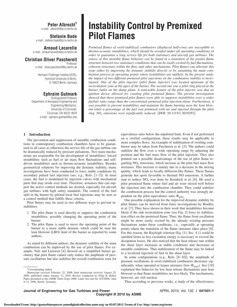
The stability map for the different cases defined in Sec. 3.1 isshown in Fig. 3. While thermo-acoustic instabilities occurred forthe cases with the 200 mm diameter combustor outlets, the case
Table 1 Investigated cases without pilot ring injection. Allcases with PFI injection were conducted with 7.5 kg/h PFI airmass flow rate at �PFI=1.1.
Cases
Preheattemperature
�K�
Outletdiameter
�mm�
PFIinjection
�–�
Baseline-550 K 550 200 NoPFI-550 K 550 200 YesPFI-550 K-65 mm 550 65 YesPFI-300 K 300 200 Yes
Table 2 Investigated cases with pilot ring injection. All testcases were conducted at a main air preheat temperature of 550K.
Cases
PFIair
�kg/h�
PFIfuel
�kg/h�
PRair
�kg/h�
PRfuel
�kg/h�
Baseline 1 0 0 0Premixed ring 1 0 15 0.96Diffusion ring 1 0 0 0.96Air ring 1 0 15 0
APRIL 2010, Vol. 132 / 041501-3
3 Terms of Use: http://asme.org/terms
cwctbwwlo�
bccd
5qcos
Fetw
Fc
0
Downloaded Fr
onducted with the 65 mm orifice remained stable within thehole investigated operating range and became unstable only
lose to the LBO, independent of the preheat temperature. Athose points low frequency pressure oscillations at 3–7 Hz coulde detected. The cause is possibly an incomplete combustionhere fuel/air mixture pockets are ignited close to the hot inneralls and hot exhaust gases. The amplitudes of the rms pressure
evel for the “baseline-550 K” case were very low near lean blow-ut at �total�0.47 but increased significantly with increasingtotal.The PFI-550 K case showed high level thermo-acoustic insta-
ilities at 0.47��total�0.6. Out of this region, i.e., extremelylose to the lean blowout limit and at condition �total�0.6, theombustion was stable. The PFI-300 K case showed unstable con-itions with a high rms pressure level at �total�0.67.
4.1 Rayleigh Index. The instabilities found for the cases PFI-50 K and PFI-300 K were more closely investigated to betteruantify the intensity of the instabilities. The OH-hemiluminescence �OH�� and the pressure fluctuations p� of thescillating premixed flame were simultaneously recorded, ashown in Fig. 4 for the PFI-550 K case at �total=0.55. The phase
ig. 3 Stability map of a swirl-stabilized combustion for differ-nt preheat air temperatures of 300 K and 550 K and combus-ion outlet diameters of 65 mm and 200 mm. The ignition deviceas in all cases off, so that no PFI flame was generated.
ig. 4 OH-chemiluminescence and pressure signals for the
ase PFI-550 K at �total=0.5541501-4 / Vol. 132, APRIL 2010
om: http://gasturbinespower.asmedigitalcollection.asme.org/ on 05/07/201
shift of less than 90 deg between these two signals indicatesclearly unstable conditions. Also the Rayleigh index R, calculatedby the formula
R =�0
time
p��t� · �OH���t�dt � dissipation losses �1�
was fulfilled.
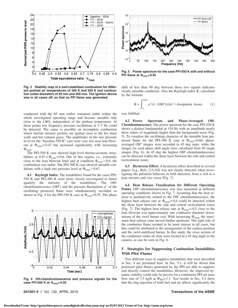
4.2 Power Spectrum and Phase-Averaged OH-Chemiluminescence. The power spectrum for the case PFI-550 Kshows a distinct fundamental at 110 Hz with an amplitude nearlythree orders of magnitude higher than the background noise �Fig.5�. To visualize the oscillating character of the unstable lean pre-mixed flame for the PFI-300 K case at �total=0.66, phase-averaged OH� images were recorded in 45 deg steps, while theimages for each phase shift angle were calculated from 40 singleimages �Fig. 6�. At 45 deg the highest OH�-chemiluminescencecan be detected within the shear layer between the side and centralrecirculation zones.
4.3 Hysteresis Effect. A hysteresis effect described in severalpapers �e.g., Refs. �13,10�� was not clearly detected when inves-tigating the pulsation behavior in both direction, from a rich to alean mixture and vice versa �Fig. 7�.
4.4 Heat Release Visualization for Different OperatingPoints. OH�-chemiluminescence was also measured at differentoperating conditions shown in Fig. 7. Assuming that the heat re-lease is qualitatively related to the OH�-chemiluminescence, thehighest heat release rate at �total�0.6 could be detected withinthe shear layer between the side and central recirculation zones�Fig. 7�. The highest heat release rate at �total�0.5 close to thelean blowout was approximately one combustor diameter down-stream of the swirl burner exit. With increasing �total, the maxi-mum heat release zone moved further upstream. The right side ofthe combustor flame seemed to be more intense in all cases, butthis could be attributed to the arrangement of the camera positionand the swirl-stabilized burner. In this study, the cross section ofthe combustor outlet air slots were located at a 45 deg angle to thecamera, as can be seen in Fig. 6.
5 Strategies for Suppressing Combustion InstabilitiesWith Pilot Flames
Two different ways to suppress instabilities that were describedin Sec. 4 are presented here. In Sec. 5.1, it will be shown thatpremixed pilot flames generated by the PFI are able to suppressand directly control the instabilities. However, the improved dy-namic stability could only be proven for a continuous PFI air massflow rate of 7.5 kg/h at �PFI=1.1. Test results in Sec. 5.2 show
Fig. 5 Power spectrum for the case PFI-550 K with and withoutPFI flame at �total=0.55
that the ring injection of both fuel and air affects significantly the
Transactions of the ASME
3 Terms of Use: http://asme.org/terms

pb
pffb�s
Tah5w
Fapplcb
J
Downloaded Fr
ressure oscillation of the main combustion and is caused mainlyy a higher jet momentum through the pilot ring.
5.1 Active Control of Instabilities. Preliminary tests wereerformed to investigate the effectiveness of the PFI lance. In theollowing, we will only show operating conditions that were ef-ective �see Figs. 8–11�. All rms pressure levels were normalizedy the background noise of the baseline case baseline-550 K attotal=0.45. The test conditions of the results presented in this
ection are shown in Sec. 3.1.
5.1.1 Response Behavior for PFI Flame On/Off Conditions.wo highly unstable conditions were chosen for the investigationt �total=0.55 and at 0.58 for 550 K preheated air and anotherighly unstable condition at �total=0.66 for nonpreheated air. The50 K case is shown in Fig. 8. During the first 12 s, the PFI sparkas off, and only a small amount of premixed fuel was injected
Fig. 6 Phase-averaged OH-chemilumangles at 200 kg/h main air mass flo�total=0.66. The instability occurred at
ig. 7 OH-chemiluminescence images and rms pressure levelt different operating points for the case PFI-550 K; the spark-lug was not activated. While for the curve “rich-lean,” theressure fluctuations were investigated from a rich mixture to a
ean mixture, and the rms pressure level was recorded for theurve “lean-rich” at the starting operating point �total near lean
lowout. A hysteresis effect was not clearly visible.ournal of Engineering for Gas Turbines and Power
om: http://gasturbinespower.asmedigitalcollection.asme.org/ on 05/07/201
�without PFI flame�. This was not enough to suppress the insta-bilities. Then, a periodic PFI flame was generated by the PFIspark, and the instability was completely suppressed. Instabilitiesat �total=0.66 for nonpreheated air could be suppressed when thesparkplug was activated, as can be seen in Fig. 9. Within the first12 s, a PFI flame was generated by the activated sparkplug, andthe rms pressure level could be held to a very low level. Eventhough the sparkplug was switched off after 12 s, the combustionremained in a stable mode for approximately 6 s before becomingunstable. After 56 s, the sparkplug was activated again, and theinstability was instantly suppressed. The time delay of severalseconds between the switching off of the spark and the initiationof instabilities could be related to the fact that the flame front wasstabilized inside of the swirl burner even though the PFI flamewas already off.
5.1.2 Overall Dynamic Stability With PFI Flames. The insta-bilities shown for the cases PFI-300 K and PFI-550 K could becompletely suppressed by the presence of the premixed PFI flame�Figs. 10 and 11�. The PFI changed the heat release distributionwithin the flame front, as can be seen in Fig. 10, and thus affectedthe dynamic stability. The results are consistent with the investi-gation of Paschereit et al. �14�.
5.1.3 Emissions. The impact of the instabilities on the emis-sion behavior can be seen in Fig. 12, where the NOx emissionswere recorded at different operating conditions and plotted versusthe total equivalence ratio ��total�. The curve referred to as “PFIflame-off” was recorded when the PFI fuel/air mixture was notignited and therefore corresponds to PFI-550 K, as described inSec. 4. Furthermore, the cases with activated PFI flame are re-ferred to as “PFI flame” in the following.
With PFI flame, NOx emissions were reduced when comparedwith the unstable baseline case. This is in agreement with Pas-chereit and Gutmark �15�, who showed that unstable premixedcombustion may increase NOx emissions. It is interesting to notethat the NOx emissions between the PFI flame and the PFI flame-off case are similar in stable regions ��total�0.6, compare Fig.10�, while the emissions significantly differ within the unstableregion �0.5��total�0.6�. Therefore, higher NOx emissions aregenerated mainly by flame temperature peaks �induced by fuel/airratio oscillations� during thermo-acoustic instabilities and not by
cence images at different phase shiftrate and 300 K nonpreheated air forHz.
inesw82
the PFI flame itself.
APRIL 2010, Vol. 132 / 041501-5
3 Terms of Use: http://asme.org/terms

tstp
FPq
Ftw
0
Downloaded Fr
5.2 Passive Control of Instabilities. After having shown thathe actively controlled pilot �PFI� could reduce significantly pres-ure pulsations and emissions, it was of further interest to inves-igate a premixed pilot located closer to the outer shear layer. Ailot ring was installed at the burner dump plane �Fig. 2�, where
Fig. 8 Time signal of the pressure fluctuations for the cflame. The frequency of the PFI flame was 110 Hz.
ig. 9 Time signal of the pressure fluctuations for the caseFI-300 K with and without PFI flame at �total=0.66. The fre-uency of the PFI flame was 110 Hz.
ig. 10 Comparision of the OH-chemiluminescence betweenhe side and central recirculation zones for the case PFI-550 K
ith and without PFI flame41501-6 / Vol. 132, APRIL 2010
om: http://gasturbinespower.asmedigitalcollection.asme.org/ on 05/07/201
fuel or a fuel/air mixture could be injected directly into the shearlayer. A detailed overview of the parameter setup used for this testand the definition of the cases can be found in Sec. 3.2.
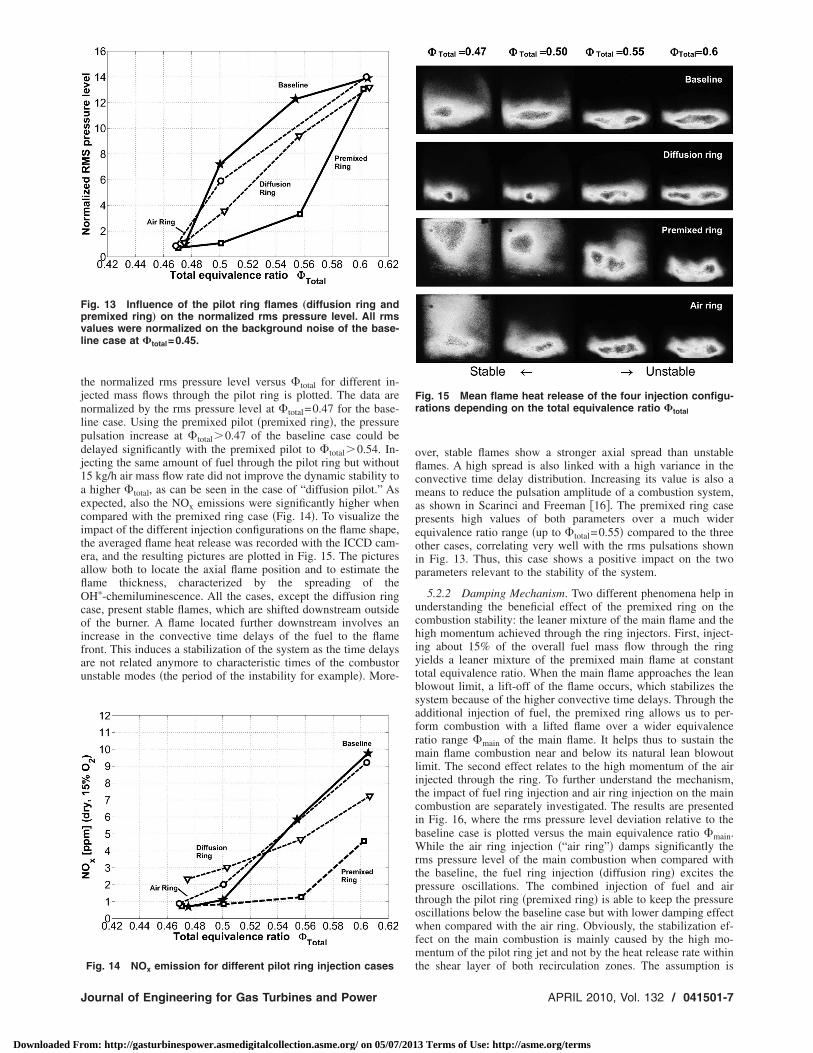
5.2.1 Advantages of Premixed Pilot Ring Injection. In Fig. 13,
e PFI-550 K at �total=0.55 and 0.61 with and without PFI
Fig. 11 rms pressure level for the case PFI-300 K with andwithout PFI flame. All rms values are normalized on the back-ground noise of the baseline case at �total=0.45.
Fig. 12 NOx emission for the case baseline-550 K and for the
as
case PFI-550 K with and without PFI flame
Transactions of the ASME
3 Terms of Use: http://asme.org/terms
tjnlpdj1aeciteaflOcoifau
Fpvl
J
Downloaded Fr
he normalized rms pressure level versus �total for different in-ected mass flows through the pilot ring is plotted. The data areormalized by the rms pressure level at �total=0.47 for the base-ine case. Using the premixed pilot �premixed ring�, the pressureulsation increase at �total�0.47 of the baseline case could beelayed significantly with the premixed pilot to �total�0.54. In-ecting the same amount of fuel through the pilot ring but without5 kg/h air mass flow rate did not improve the dynamic stability tohigher �total, as can be seen in the case of “diffusion pilot.” As
xpected, also the NOx emissions were significantly higher whenompared with the premixed ring case �Fig. 14�. To visualize thempact of the different injection configurations on the flame shape,he averaged flame heat release was recorded with the ICCD cam-ra, and the resulting pictures are plotted in Fig. 15. The picturesllow both to locate the axial flame position and to estimate theame thickness, characterized by the spreading of theH�-chemiluminescence. All the cases, except the diffusion ring
ase, present stable flames, which are shifted downstream outsidef the burner. A flame located further downstream involves anncrease in the convective time delays of the fuel to the flameront. This induces a stabilization of the system as the time delaysre not related anymore to characteristic times of the combustornstable modes �the period of the instability for example�. More-
ig. 13 Influence of the pilot ring flames „diffusion ring andremixed ring… on the normalized rms pressure level. All rmsalues were normalized on the background noise of the base-ine case at �total=0.45.
Fig. 14 NOx emission for different pilot ring injection cases
ournal of Engineering for Gas Turbines and Power
om: http://gasturbinespower.asmedigitalcollection.asme.org/ on 05/07/201
over, stable flames show a stronger axial spread than unstableflames. A high spread is also linked with a high variance in theconvective time delay distribution. Increasing its value is also ameans to reduce the pulsation amplitude of a combustion system,as shown in Scarinci and Freeman �16�. The premixed ring casepresents high values of both parameters over a much widerequivalence ratio range �up to �total=0.55� compared to the threeother cases, correlating very well with the rms pulsations shownin Fig. 13. Thus, this case shows a positive impact on the twoparameters relevant to the stability of the system.
5.2.2 Damping Mechanism. Two different phenomena help inunderstanding the beneficial effect of the premixed ring on thecombustion stability: the leaner mixture of the main flame and thehigh momentum achieved through the ring injectors. First, inject-ing about 15% of the overall fuel mass flow through the ringyields a leaner mixture of the premixed main flame at constanttotal equivalence ratio. When the main flame approaches the leanblowout limit, a lift-off of the flame occurs, which stabilizes thesystem because of the higher convective time delays. Through theadditional injection of fuel, the premixed ring allows us to per-form combustion with a lifted flame over a wider equivalenceratio range �main of the main flame. It helps thus to sustain themain flame combustion near and below its natural lean blowoutlimit. The second effect relates to the high momentum of the airinjected through the ring. To further understand the mechanism,the impact of fuel ring injection and air ring injection on the maincombustion are separately investigated. The results are presentedin Fig. 16, where the rms pressure level deviation relative to thebaseline case is plotted versus the main equivalence ratio �main.While the air ring injection �“air ring”� damps significantly therms pressure level of the main combustion when compared withthe baseline, the fuel ring injection �diffusion ring� excites thepressure oscillations. The combined injection of fuel and airthrough the pilot ring �premixed ring� is able to keep the pressureoscillations below the baseline case but with lower damping effectwhen compared with the air ring. Obviously, the stabilization ef-fect on the main combustion is mainly caused by the high mo-mentum of the pilot ring jet and not by the heat release rate within
Fig. 15 Mean flame heat release of the four injection configu-rations depending on the total equivalence ratio �total
the shear layer of both recirculation zones. The assumption is
APRIL 2010, Vol. 132 / 041501-7
3 Terms of Use: http://asme.org/terms

c�ts
6
wicapcasmoct
A
m
Fm
Fc
0
Downloaded Fr
onfirmed when looking at the OH� images corresponding tomain�0.51 in Fig. 17. They confirm that the air ring injection has
he most stabilizing effect at constant �main by increasing thepreading of the flame.
ConclusionActive and passive control methods for instability suppression
ere successfully applied on a swirl-stabilized combustor. Stabil-ty maps of the combustor were recorded for different operatingonditions. Unstable conditions were actively controlled by using
periodically ignited premixed flame. It reduced significantlyressure pulsations and NOx emissions. Regarding the passiveontrol method, a continuous premixed pilot ring injection locatedt the combustor dump plane show reduced pulsations and emis-ions. The damping effect is mainly achieved by the high jet mo-entum through the pilot ring. Moreover, the combined injection
f fuel and air through the ring influences and sustains signifi-antly the spreading and the lift-off of the main flame that appearso be another damping source for pressure oscillations.
cknowledgmentWe gratefully acknowledge the work of Willi Postel who has
ig. 16 Impact of different pilot ring injection cases on theain flame stabilization
ig. 17 Mean flame heat release of the four injectiononfigurations
anufactured the PFI lance. Furthermore, we gratefully acknowl-
41501-8 / Vol. 132, APRIL 2010
om: http://gasturbinespower.asmedigitalcollection.asme.org/ on 05/07/201
edge Tyler Jensen who helped us during preliminary tests of thePFI lance.
NomenclatureTCCW � wall temperature of the combustion chamberOH� � OH-chemiluminescence
�total � total equivalence ratio calculated from �mainand �PFI
�main � main equivalence ratio of the main combustion�PFI � equivalence ratio of the flame produced by the
pilot flame injector�pilot � equivalence ratio of the pilot flame
p� � pressure fluctuation within the combustionchamber
R � Rayleigh index
References�1� Candel, S. M., 1992, “Combustion Instabilities Coupled by Pressure Waves
and Their Active Control,” 24th Symposium �International� on Combustion,The Combustion Institute, pp. 1277–1296.
�2� Hoffmann, S., Weber, G., Judith, H., Hermann, J., and Orthmann, A., 1998,“Application of Active Combustion Control to Siemens Heavy Duty Gas Tur-bines,” Applied Vehicle Technology Panel Symposium, Lisbon, Portugal, Vol.14.
�3� Paschereit, C. O., Gutmark, E., and Weisenstein, W., 1999, “Control of Ther-moacoustic Instabilities in a Premixed Combustor by Fuel Modulation,” AIAAPaper No. 99-0711.
�4� Nair, S., and Lieuwen, T., 2003, “Acoustic Detection of Imminent Blowout inPilot and Swirl Stabilized Combustors,” ASME Paper No. GT2003-38074.
�5� Paschereit, C. O., Flohr, P., and Gutmark, E. J., 2006, “Combustion Control byVortex Breakdown Stabilization,” ASME J. Turbomach., 128�4�, pp. 679–688.
�6� Kendrick, D. W., Anderson, T. J., Sowa, W. A., and Snyder, T., 1999, “Acous-tic Sensitivities of Lean-Premixed Fuel Injectors in a Single Nozzle Rig,”ASME J. Eng. Gas Turbines Power, 121, pp. 429–436.
�7� Bradley, D., Gaskell, P. H., Gu, X. Y., Lawes, M., and Scott, M. J., 1998,“Premixed Turbulent Flame Instability and NO Formation in a Lean-BurnSwirl Burner,” J. Propul. Power, 21�1�, pp. 32–39.
�8� Fritsche, D., 2005, “Origin and Control of Thermoacoustic Instabilities in LeanGas Turbine Combustion,” Ph.D. thesis, Swiss Federal Institute of TechnologyZurich.
�9� Lenz, M., 1998, “Experimentelle Optimierung des Stabilitaetsverhalten vonGasturbinenbrenner,” University Erlangen-Nuernberg, Chair of TechnicalThermodynamics, Germany, Technical Report.
�10� Seo, S., 1999, “Parametric Study of Lean Premixed Combustion Instability ina Pressurized Model Gas Turbine Combustor,” Ph.D. thesis, Department ofMechanical and Nuclear Engineering, The Pennsylvania State University, Uni-versity Park.
�11� Keller, J., and Sattelmayer, T., 1991, “Double-Cone Burners for Gas TurbineType 9 Retrofit Application,” presented at the 19th International Congress onCombustion Engines �CIMAC�, Florence.
�12� Albrecht, P., Speck, S., Schimek, S., Bauermeister, F., Paschereit, C. O., andGutmark, E., 2007, “Lean Blowout Control Using an Auxiliary PremixedFlame in a Swirl-Stabilized Combustor,” AIAA Paper No. 2007-5632.
�13� Lepers, J., Krebs, W., Prade, B., Flohr, P., Pollarolo, G., and Ferrante, A.,2005, “Investigation of Thermoacoustic Stability Limits of an Annular GasTurbine Combustor Test-Rig With and Without Helmholtz Resonators,” ASMEPaper No. GT-2005-68246.
�14� Paschereit, C., Schuermanns, B., and Bueche, D., 2003, “Combustion ProcessOptimization Using Evolutionary Algorithm,” ASME Paper No. 2003-GT-38393.
�15� Paschereit, C. O., and Gutmark, E. J., 2008, “Combustion Instability and Emis-sions Control by Pulsating Fuel Injection,” ASME J. Turbomach., 130�1�, pp.12–19.
�16� Scarinci, T., and Freeman, C., 2000, “The Propagation of a Fuel-Air RatioDisturbance in a Simple Premixer and Its Influence on Pressure Wave Ampli-
fication,” ASME Paper No. 2000-GT-0106.Transactions of the ASME
3 Terms of Use: http://asme.org/terms